

Yardistry YM12944 Installation And Operating Instructiontructions
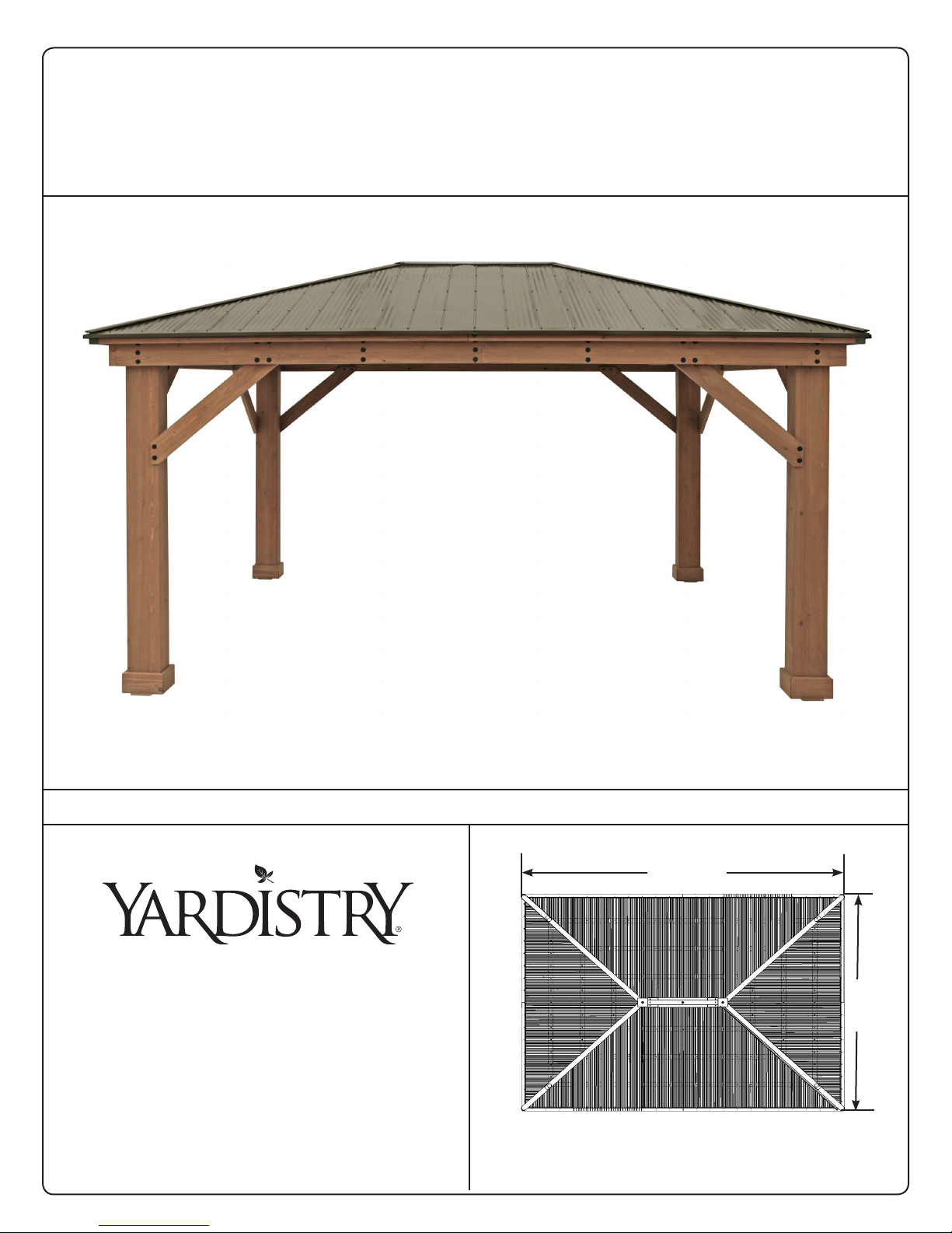
16'-1"
12'-2"
12’ x 16’ WOOD GAZEBO
with ALUMINUM ROOF
Installaon and Operang Instrucons – YM12944
Revised 12-17-2018
Yardistry – North America
Toll Free Customer Support: 1.888.509.4382
info@yardistrystructures.com
www.yardistrystructures.com
Yardistry / Selwood Products – Europe
Customer Support: +44 1284 852569
parts@selwoodproducts.com
www.selwoodproducts.com
HEIGHT:
10’4” / 3.15m
16’ 1”
4.9 m
12’ 1”
3.7 m
Y40000-944
Important Safety Notice!
Yardistry components are intended for privacy, decorative and ornamental use only.
Product is NOT INTENDED for the following:
• A safety barrier to prevent unsupervised access to pools, hot tubs, spas or ponds.
• As load bearing support for a building, structure, heavy objects or swings.
• Used in structures that trap wind, rain or snow that would create extra load on the
product.
Accumulated snow must be removed from roof.
DO NOT climb or walk on roof for any reason.
Permanent structures may require a building permit. As the purchaser and or installer of this
product you are advised to consult local planning, zoning and building inspection departments for
guidance on applicable building codes and/or zoning requirements.
Wood is NOT ame retardant and will burn. Grills, re pits and chimineas are a re hazard if
placed too close to a Yardistry structure. Consult user’s manual of the grill, re pit or chimnea for
safe distances from combustible materials.
Wear gloves to avoid injury from possible sharp edges of individual elements before assembly.
During installation, follow all safety warnings provided with your tools and use OHSA
approved safety glasses. Some structures may require two or more people to install safely.
Check for underground utilities before digging or driving stakes into the ground!
It is important during assembly to closely follow the instructions, complete the assembly
on a solid level surface and that you follow the instruction to square up, level and anchor the
structure, this will reduce the gap at wood connections during assembly.
General Information
General Information: Wood components are manufactured with Cedar (C. Lanceolata)
which is protected with factory applied water-based stain. Knots, small checks (cracks)
and weathering are naturally occurring and do not aect the strength of the product.
Annual application of a water-based water repellent sealant or stain is important and will
help reduce weathering and checks.
www.yardistrystructures.com
Questions?
Call toll free or write us at:
1 (888) 509-4382
info@yardistrystructures.com
Patents Pending
2 support@yardistrystructures.com

Limited Warranty
Yardistry warrants that this product is free from defect in materials and workmanship for a
period of one (1) year from the original date of purchase. In addition, for any product with
lumber, all lumber is warranted for ve (5) years against rot and decay. This warranty applies
to the original owner and registrant and is non-transferable.
Regular maintenance is required to assure the integrity of your product and is a requirement of
the warranty. This warranty does not cover any inspection costs.
This Limited Warranty does not cover:
• Labour for replacement of any defective item(s);
• Incidental or consequential damages;
• Cosmetic defects which do not aect performance or integrity;
• Vandalism; improper use or installation; acts of nature, including but not limited to wind,
storms, hail, oods, excessive water exposure;
• Minor twisting, warping, checking or any other natural occurring properties of wood that do
not aect performance or integrity.
Yardistry products have been designed for safety and quality. Any modications made to
the original product could damage the structural integrity of the product leading to failure
and possible injury. Yardistry cannot assume any responsibility for modied products.
Furthermore, modication voids any and all warranties.
This product is warranted for RESIDENTIAL USE ONLY. Yardistry disclaims all other
representations and warranties of any kind, express or implied.
This Warranty gives you specic legal rights. You may have other rights as well which vary from state to state
or province to province. This warranty excludes all consequential damages, however, some states/provinces
do not allow the limitation or exclusion of consequential damages, and therefore this limitation may not apply
to you.
3 support@yardistrystructures.com
Instructions for Proper Maintenance
Your Yardistry structure is designed and constructed of quality materials. As with all outdoor
products it will weather and wear. To maximize the enjoyment, safety and life of your structure
it is important that you, the owner, properly maintain it.
HARDWARE:
• Check metal parts for rust. If found, sand and repaint using a non-lead paint complying
with 16 CFR 1303.
• Inspect and tighten all hardware after completion of assembly; after rst month of use; and
then annually. Do not over-tighten as to cause crushing and splintering of wood.
• Check for sharp edges or protruding screw threads, add washers if required.
WOOD PARTS:
• Applying a water repellent or stain (water-based) on a yearly basis is important
maintenance to maintain maximum life and performance of the product.
• Check all wood members for deterioration, structural damage and splintering. Sand down
splinters and replace deteriorated wood members. As with all wood, some checking and
small cracks in grain is normal
• Some gapping may occur at some wood connections.
Assembly Guides
Tools Required:
• Tape Measure
• Carpenters Level
• Standard or Cordless Drill
• Claw Hammer
• 7/16” & 9/16” Wrench
Symbols:
Throughout these instructions symbols are provided in the top, right-hand corner of the page.
• Use Help, where this is shown, 2, 3 or 4
people are required to safely complete
this step. To avoid injury or damage to the
assembly make sure to get some help.
• Pre-drill a pilot hole before fastening
screw or lag to prevent splitting of wood.
• 8’ Step Ladder
• Safety Glasses
• Adult Helper
• Safety Gloves
• Hard Hat
• 6’ Step Ladder x 3
• Square
• Rachet
• 7/16, 1/2 & 9/16 Socket
• Use a measuring tape to assure proper
location
If you dispose of your Yardistry structure: Please disassemble and dispose of your
unit so that it does not create any unreasonable hazards at the time it is discarded. Be
sure to follow your local waste ordinances.
4 support@yardistrystructures.com

Assembly Tips
Following are some helpful tips to make the assembly process smooth and ecient.
PRE-ASSEMBLIES:
(i.e. Post and Beam Assemblies, Roof Rafter Assembly, etc)
• Work on a raised, solid and at surface such as, a table or saw horse.
• Keep all connections ush where shown in the instructions.
• When assembling the beams keep parts at, straight and snug when
connecting.
METAL PARTS:
• Roong material may have sharp edges, wear safety gloves.
• Remove all plastic covering, on both sides of the metal panels, directly
before installing each piece.
• Place roong material on a non-abrasive surface before and after assembly
as it can bend, dent and scratch easily.
• The roong screws can easily crush the roof panels and roof edges when
using a power drill. We recommend hand tightening the roong screws so
they sit snug and tight to the roong material.
5 support@yardistrystructures.com
Post to Post
Post to Post
14'-10"
16'-7"
Plinth to Plint
h
9'-8"
Plinth to Plinth
13'-3"
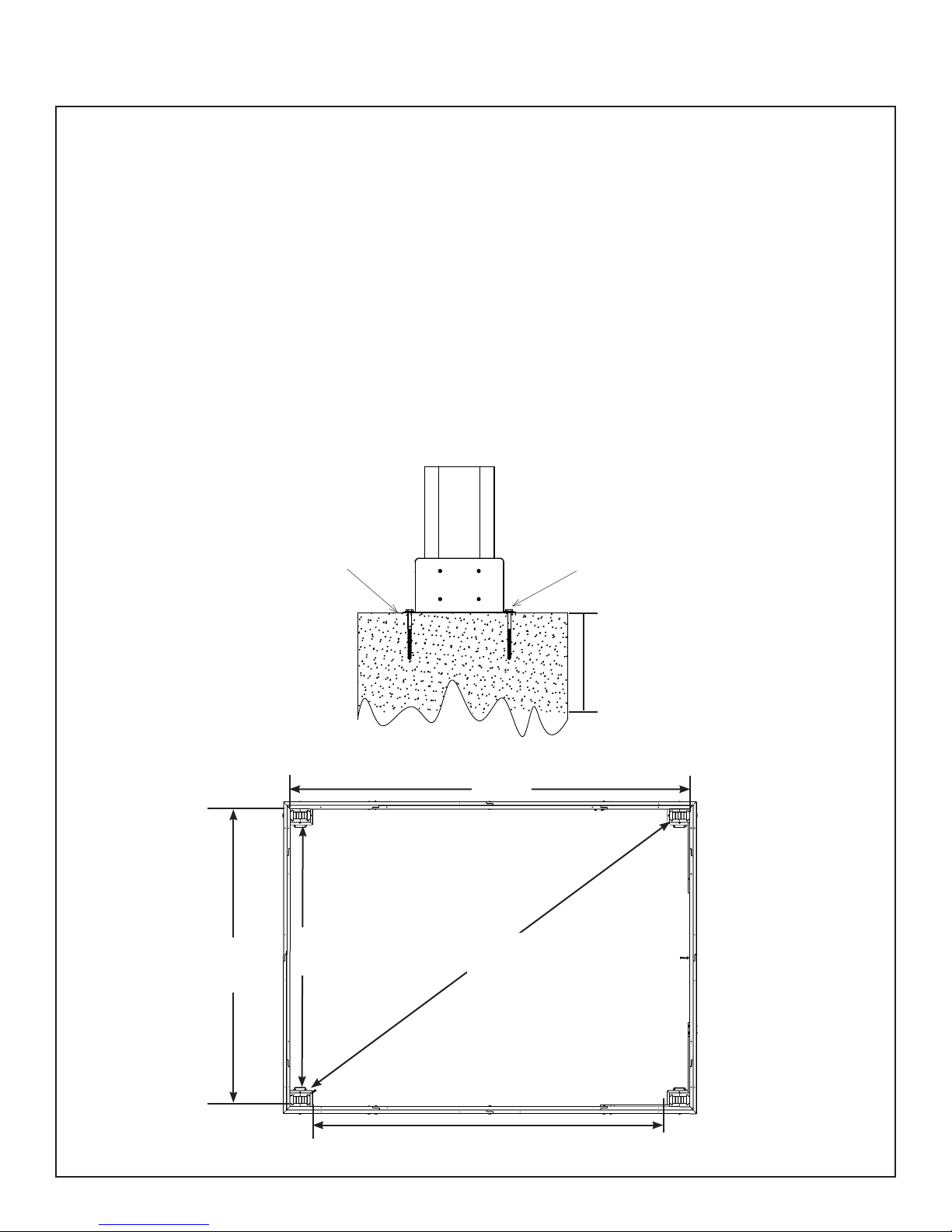
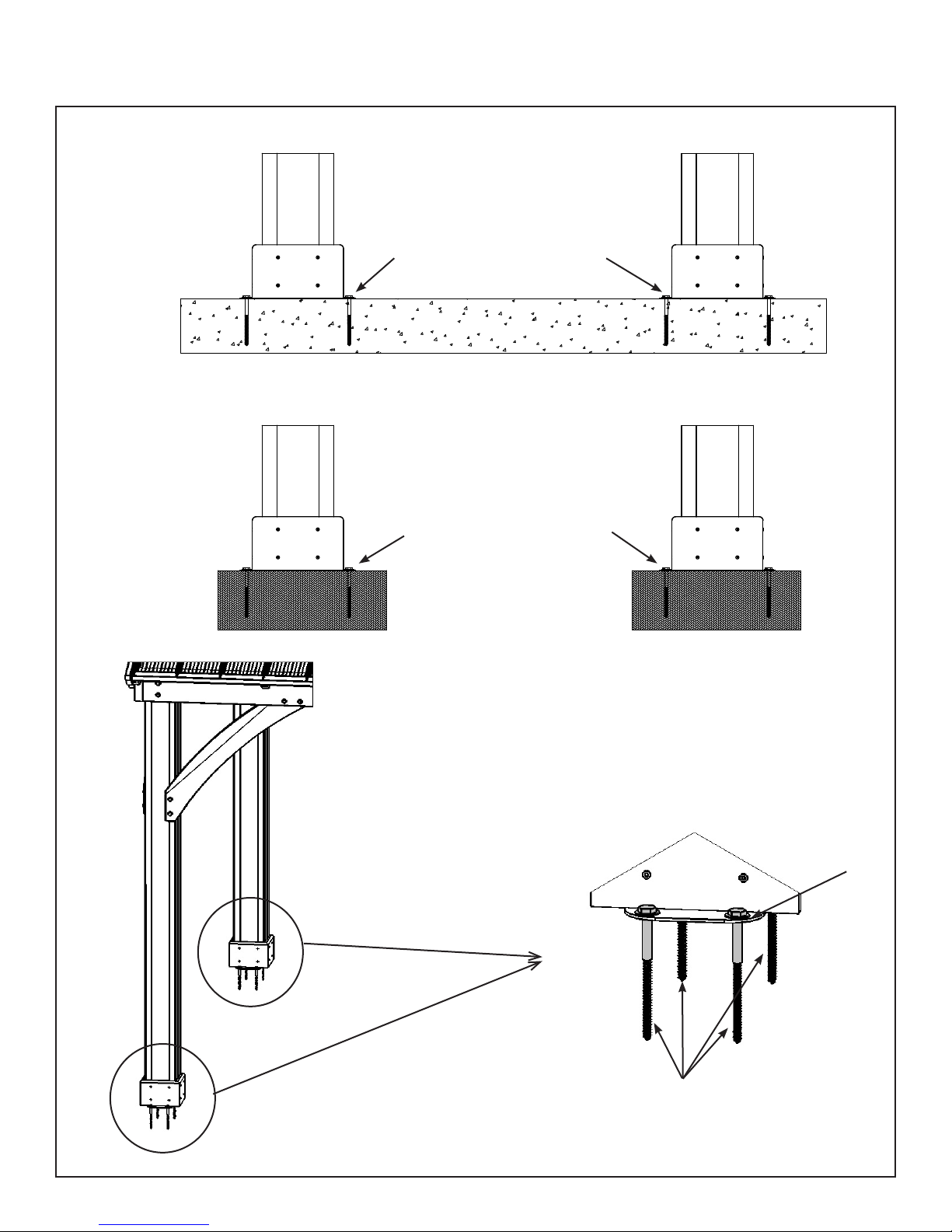
Permanent Installation Examples
Note: It is critically important you start with square, solid and level footings, concrete
pad or deck to attach your Pergola Room.
We supply Post Mounts with this structure which gives you the exibility to permanently install your structure
to a pre-existing or new wood or concrete surface.
• The hardware to attach the Post Mount to the structure is included.
• The hardware to mount the structure permanently will need to be purchased separately at your local
hardware store.
If you are mounting to concrete footers see below for the correct locations and placement. Please double
check for possibility of any underground utilities such as gas, telephone, cable or sprinkler lines.
Following are some examples of how to mount the structure to wood or concrete surfaces.
Refer to your local building and city codes, ordinances, neighbourhood covenants, or height restrictions
regarding this type of structure for guidance on acceptable installation requirements.
Concrete Footer
10’ 10-3/8”
3.31 m
Post to Post
Post Mount
9’ 8-1/2”
2.96 m
Plinth to Plinth
Post to Post
14’ 10-3/8”
4.53 m
16’ 7-3/8”
5.06 m
Post to Post
Anchoring Hardware not included
To
Required
Depth
6 support@yardistrystructures.com
Plinth to Plinth
13’ 2-1/2”
4.03 m
Permanent Installation Examples cont.
Concrete Patio [min. 11’ 10-3/8” x 15’ 10-3/8” (3.616 m x 4.836 m)] with 6” (15.24 cm) clearance on all sides
Anchoring Hardware not included
Wood Deck [min. 11’ 10-3/8” x 15’ 10-3/8” (3.616 m x 4.836 m)] with 6” (15.24 cm)clearance on all sides
Anchoring Hardware not included
Post
Mount
Anchoring Hardware (not included)
Post Mounts have a 1/2” (12.7 mm)
diameter hole for anchoring hardware.
7 support@yardistrystructures.com
Part Identification ( )
8pc. (460) Plinth Long FSC
23.8 x 133.4 x 276.2mm (15/16 x 5¼ x 10-7/8")
Dimensions are approximate and are shown to assist in the identification of parts for
assembly. Actual dimensions may be smaller or larger.
8pc. (459) Plinth FSC
23.8 x 133.4 x 200mm (15/16 x 5¼ x 7-7/8")
Y50229-460
4pc. (786) Straight Gusset Right FSC 38.1 x 139.7 x 1096.2mm (1½ x 5½ x 43-3/16")
Y50229-786
4pc. (787) Straight Gusset Left FSC 38.1 x 139.7 x 1096.2mm (1½ x 5½ x 43-3/16")
Y50229-787
2pc. (660) Left Beam Short FSC 38.1 x 177.8 x 1769.7mm (1½ x 7 x 69-5/8")
Y70229-660
2pc. (661) Right Beam Short FSC 38.1 x 177.8 x 1769.7mm (1½ x 7 x 69-5/8")
Y70229-661
2pc. (664) Centre Beam Short FSC 38.1 x 177.8 x 2422.1mm (1½ x 7 x 95-3/8")
Y50229-459
4pc. (665) End Short Beam FSC
38.1 x 177.8 x 558.6mm (1½ x 7 x 22")
Y70229-665
Y70229-664
2pc. (650) Outer End Left FSC 38.1 x 177.8 x 2379.7mm (1½ x 7 x 93-11/16")
Y70229-650
2pc. (649) Outer End Right FSC 38.1 x 177.8 x 2379.7mm (1½ x 7 x 93-11/16")
Y70229-649
2pc. (653) Inside Long Beam FSC 38.1 x 177.8 x 2667mm (1½ x 7 x 105")
Y70229-653
4pc. (656) Inside Beam FSC 38.1 x 177.8 x 1046.2mm (1½ x 7 x 41-3/16")
Y70229-656
4pc. (621) 6 x 9 Post FSC 152.4 x 228.6 x 2387.6mm (6 x 9 x 94")
NOTE: Parts have been
packed inside (621) 6 x 9
Post. Check for parts
inside the Post.
Y70229-621
8 support@yardistrystructures.com
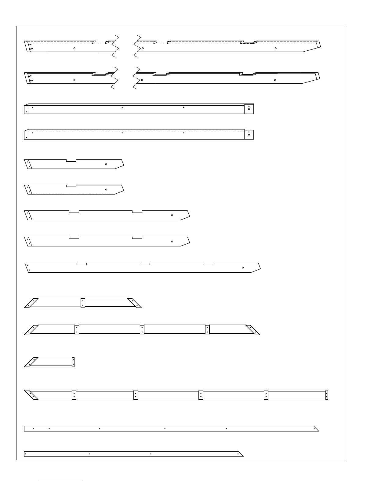
Part Identification ( )
4pc. (624) Rafter Corner Left FSC 25.4 x 88.9 x 2597.8mm (1 x 3½ x 102¼")
Y50229-624
4pc. (623) Rafter Corner Right FSC 25.4 x 88.9 x 2597.8mm (1 x 3½ x 102¼")
Y50229-623
2pc. (627) Fascia Left Short FSC 38.1 x 82.6 x 1855.5mm (1½ x 3¼ x 73-1/16")
Y50229-627
2pc. (628) Fascia Right Short FSC 38.1 x 82.6 x 1855.5mm (1½ x 3¼ x 73-1/16")
Y50229-628
4pc. (629) Rafter Short RT FSC 31.8 x 76.2 x 805.5mm (1¼ x 3 x 31-3/4")
Y50229-629
4pc. (630) Rafter Short LT FSC 31.8 x 76.2 x 805.5mm (1¼ x 3 x 31-3/4")
Y50229-630
Dimensions are approximate and are shown to assist in the identification of parts for
assembly. Actual dimensions may be smaller or larger.
4pc. (631) Rafter Centre LT FSC 31.8 x 76.2 x 1338.9mm (1¼ x 3 x 52-3/4")
Y50229-631
4pc. (632) Rafter Centre RT FSC 31.8 x 76.2 x 1338.9mm (1¼ x 3 x 52-3/4")
Y50229-632
6pc. (634) Rafter FSC 31.8 x 76.2 x 1907mm (1¼ x 3 x 75-1/16")
Y50229-634
2pc. (636) Top Strap FSC 31.8 x 76.2 x 953.8mm (1¼ x 3¼ x 37-35/64")
Y50229-636
2pc. (637) Mid Strap FSC 31.8 x 76.2 x 1908.3mm (1¼ x 3 x 75-1/8")
Y50229-637
2pc. (688) Bottom Strap RT FSC 31.8 x 76.2 x 406.3mm (1¼ x 3 x 16")
Y50229-688
2pc. (687) Bottom Strap LT FSC 31.8 x 76.2 x 2457mm (1¼ x 3 x 96-3/4")
Y50229-687
4pc. (647) Soffit Long FSC 15.9 x 41.3 x 2383mm (5/8 x 1-5/8 x 93-13/16")
Y50229-647
4pc. (648) Soffit FSC 15.9 x 41.3 x 1774.5mm (5/8 x 1-5/8 x 69-7/8")
Y50229-648
9 support@yardistrystructures.com
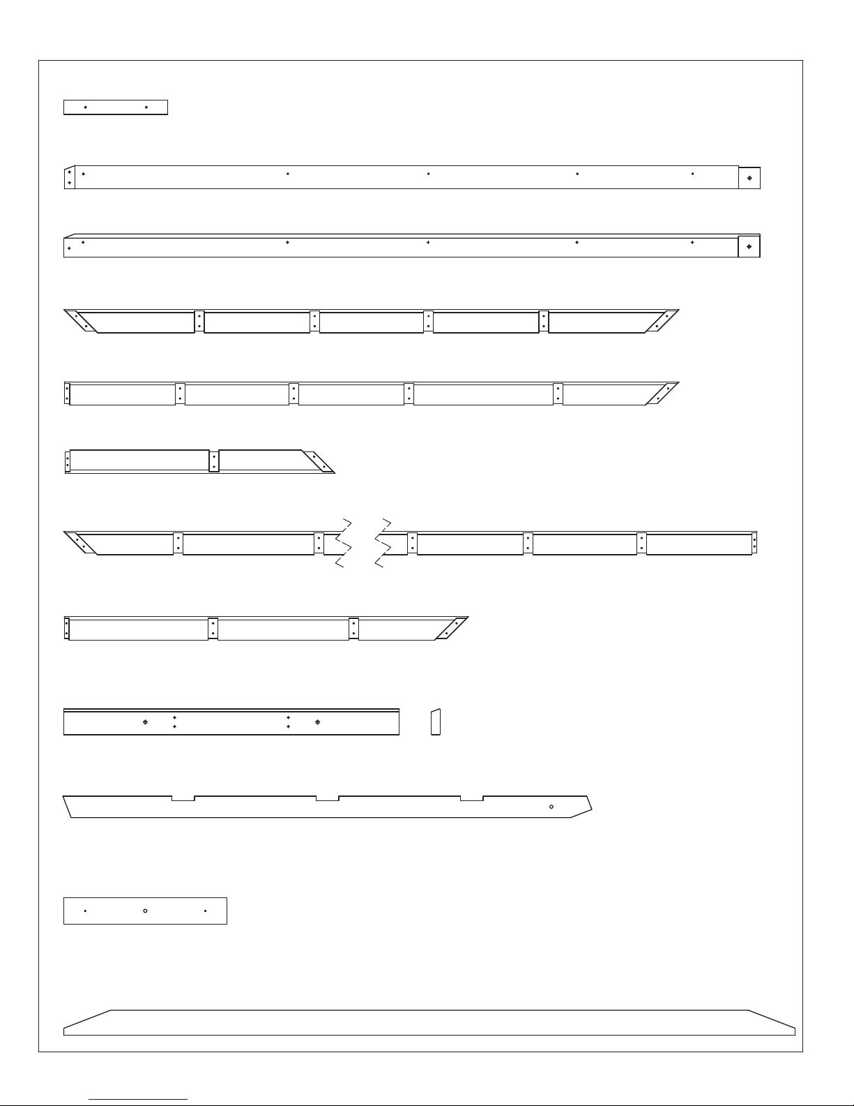
Part Identification ( )
2pc. (639) Fascia Block FSC 38.1 x 50.8 x 368mm (1½ x 2 x 14½")
Y50229-639
2pc. (626) Fascia RT Long FSC 38.1 x 82.6 x 2465.5mm (1½ x 3¼ x 97-1/16")
Y50229-626
2pc. (625) Fascia LT Long FSC 38.1 x 82.6 x 2465.5mm (1½ x 3¼ x 97-1/16")
Y50229-625
2pc. (640) Strap Top Lg FSC 31.8 x 76.2 x 2179mm (1¼ x 3 x 85-13/16")
Y50229-640
2pc. (642) Strap Mid RT FSC 31.8 x 76.2 x 2175.8mm (1¼ x 3 x 85-5/8")
Y50229-642
2pc. (641) Strap Mid LT FSC 31.8 x 76.2 x 955.9mm (1¼ x 3 x 37-5/8")
Dimensions are approximate and are shown to assist in the identification of parts for
assembly. Actual dimensions may be smaller or larger.
Y50229-641
2pc. (643) Strap Bot LT FSC 31.8 x 76.2 x 2651.4mm (1¼ x 3 x 104-3/8")
Y50229-643
2pc. (644) Strap Bot RT FSC 31.8 x 76.2 x 1431.5mm (1¼ x 3 x 56-3/8")
Y50229-644
2pc. (635) Long Roof Top FSC 31.8 x 93.8 x 1188.2mm (1¼ x 3-11/16 x 46-3/4")
Y50229-635
4pc. (633) Centre Rafter FSC 31.8 x 76.2 x 1873.6mm (1¼ x 3 x 73-3/4")
Y50229-633
2pc. (645) Spacer FSC 31.8 x 93.8 x 578.2mm (1¼ x 3-11/16 x 22-3/4")
packed inside (621) 6 x 9
NOTE: Parts have been
Y50229-645
Post. Check for parts
inside the Post.
4pc. (646) Tie FSC 31.8 x 88.9 x 2590.8mm (1¼ x 3½ x 102")
Y50229-646
10 support@yardistrystructures.com
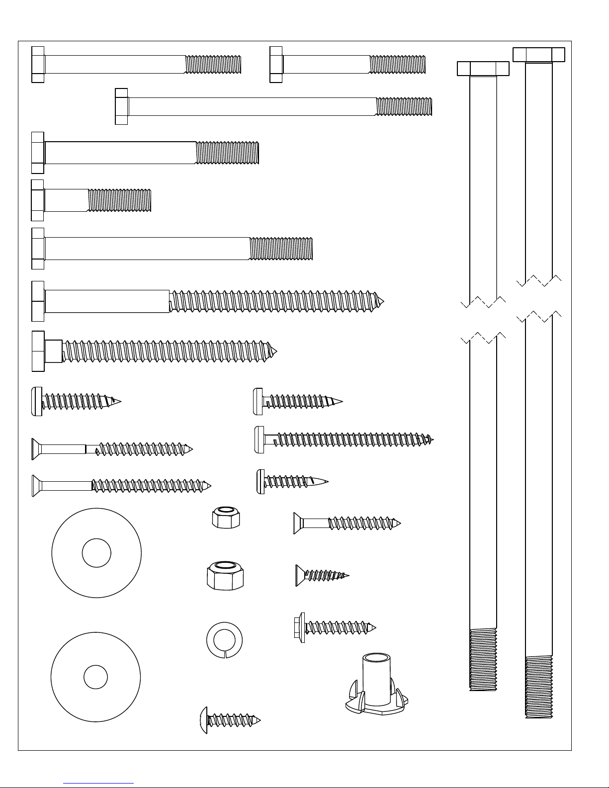
Hardware Identification ( )
12pc.
1/4 x 2-3/4 Hex Bolt - (Y07718-223)
2pc.
1/4 x 4-1/4" Hex Bolt - (Y07718-241)
30pc.
5/16 x 3" Hex Bolt - (Y07718-330)
Dimensions are approximate and are shown to assist in the identification of
parts for assembly. Actual dimensions may be smaller or larger.
26pc.
1/4 x 2 Hex Bolt - (Y07718-220)
46pc.
16pc.
12pc.
16pc.
94pc.
Hex Bolt
Hex Bolt
Lag Screw
Lag Screw
Pan Screw
(Y07718-312)
40pc.
Wood Screw #8 x 2 1/4" - (Y06091-521)
126pc.
Wood Screw
5/16 x 1-1/2"
5/16 x 3-3/4" - (Y07718-333)
5/16 x 4-3/4"
- (Y06218-343)
5/16 x 3" - (Y06218-330)
#12 x 1-1/2"
(Y06491-612)
#8 x 2 1/2" - (Y06091-522)
74pc.
Pan Screw
#10 x 1-1/4"
8pc.
Pan Screw
40pc.
Pan Screw
#10 x 2-1/2" - (Y06491-722)
#8 x 1"
(Y06491-510)
(Y06491-711)
264pc.
40pc.
- 1/4" Lock Nut
(Y08318-203)
60pc.
(Y06091-003)
12pc.
24pc.
3/8 x 1-1/4" Large Washer
(Y05118-811)
- 3/8" Lock Nut
(Y08318-803)
92pc.
5/16" Lock Washer
(Y05318-300)
24pc.
Sheet Metal Screw
#8 x 3/4"
1/4-5/16 x 1-1/4" Large Washer
11 support@yardistrystructures.com
200pc.
(Y05118-311)
(
Y06430-503)
Wood Screw #8 x 1-1/2"
Wood Screw #7 x 3/4"
304pc.
Hex Roofing Screw
#8x 1"
92pc.
5/16 - T-Nut
(Y08518-300)
(Y06091-512)
(Y06730-510)
8pc.
Hex Bolt
3/8 x 9-1/2"
(Y07718-892)
4pc.
Hex Bolt
3/8 x 12-1/2"
(Y07718-822)

Hardware Identification ( )
4pc.
- Short Panel Left
(Y01030-200)
Dimensions are approximate and are shown to assist in the identification of
parts for assembly. Actual dimensions may be smaller or larger.
4pc.
- Long Panel Right
(Y01030-197)
4pc.
- Long Panel Left
(Y01030-198)
2pc.
Roof Edge Left 72.2 - (Y01030-134)
2pc.
Roof Edge Right 72.2 - (Y01030-135)
8pc.
Ridge Clip 102.5 - (Y01030-133)
2pc.
Roof Edge Right 96.2 - (Y01030-136)
2pc.
Roof Edge Left 96.2 - (Y01030-201)
4pc.
Ridge Cap Long 81.5 (Y01030-131)
4pc.
- Middle Panel
(Y01030-196)
1pc.
- Roof Panel Set
(Y70830-195)
4pc.
- Short Panel Right
(Y01030-199)
4pc.
Ridge Cap Short 25.2 (Y01030-132)
1pc.
- Weather Seal
Ridge Clip (8Pk)
(Y70818-074)
12 support@yardistrystructures.com
1pc.
- Gazebo ID Plaque
(Y70800-104)
2pc.
- 50mm Hook
(Y00418-050)
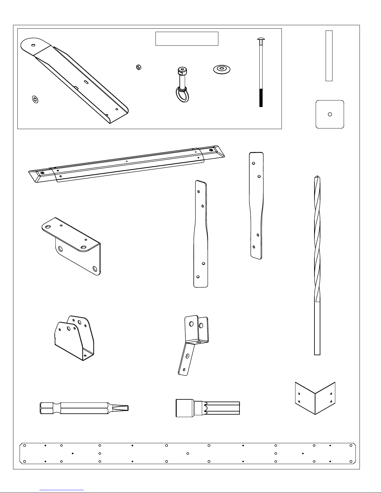
Hardware Identification ( )
4pc.
Roof Peak Bracket
(Y00429-125)
Dimensions are approximate and are shown to assist in the identification of
parts for assembly. Actual dimensions may be smaller or larger.
1pc.
Roof Peak Set
-
(Y70829-215)
3pc.
Spring Clip
(Y09490-001)
1pc.
- Peak Cap Assembly
(Y70830-249)
1pc.
Mount Set (8Pk)
(Y70829-122)
- Post
3pc.
1/4" Nut
(Y08490-200)
3pc.
Loop
(Y20018-003)
3pc.
Contour Washer
(Y05918-211)
1pc.
Bracket LT (Y70829-191)
3pc.
Carriage Bolt
(Y07428-260)
-(2 Pack) 45º Twist
3pc.
Peak Post
(Y01000-094)
1pc.
Peak Bracket
(Y00429-190)
1
p
(
c
Y
.
0
-
0
1
4
/
0
8
0
"
-
D
0
r
0
ill
2
)
B
it
1pc.
Tie Wrap Bracket (8Pk)
(Y70819-106)
1pc.
#2 x 2" Robertson Driver (Y00400-005)
2pc. Long Beam Insert
- (Y00429-194)
1pc.
- (2 Pack) 45º Twist
Bracket RT (Y70829-192)
1pc.
- Roof To Beam
Bracket Set (26Pk)
(Y70819-218)
1pc.
- Hex Driver (Y00400-004)
1pc.
- Corner Cap Set (4Pk)
(Y70830-103)
13 support@yardistrystructures.com
Step 1: Inventory Parts - Read This Before Starting Assembly
STOP STOPSTOP STOP
A. This is the time for you to inventory all your hardware, wood and accessories,
referencing the parts identication sheets. This will assist you with your
assembly.
• Each step indicates which bolts and/or screws you will need for assembly, as well as
any at washers, lock washers, t-nuts or lock nuts.
B. If there are any missing or damaged pieces or you need assistance with
assembly please contact the consumer relations department directly. Call us
before going back to the store.
1-888-509-4382
support@yardistrystructures.com
C. Read the assembly manual completely, paying special attention to ANSI
warnings; notes; and safety/maintenance information on pages 1 - 4.
• Follow the instructions in order.
• This structure is designed to be assembled and installed ideally by four
people, DO NOT attempt to install alone.
• Consider the slope of elevation where you plan to install the structure. Also, check
for gas, telephone, other utilities or sprinkler line locations prior to excavating any
holes.
D. Before you discard your cartons ll out the form below.
• The carton I.D. stamp is located on the end of each carton.
• Please retain this information for future reference. You will need this information if
you contact the Consumer Relations Department.
PRODUCT NUMBER: YM12944
CARTON I.D. STAMP: __ __ __ __ __ ___ (Box 1)
CARTON I.D. STAMP: __ __ __ __ __ ___ (Box 2)
CARTON I.D. STAMP: __ __ __ __ __ ___ (Box 3)
14 support@yardistrystructures.com
12 x 16 Gazebo with Aluminum Roof
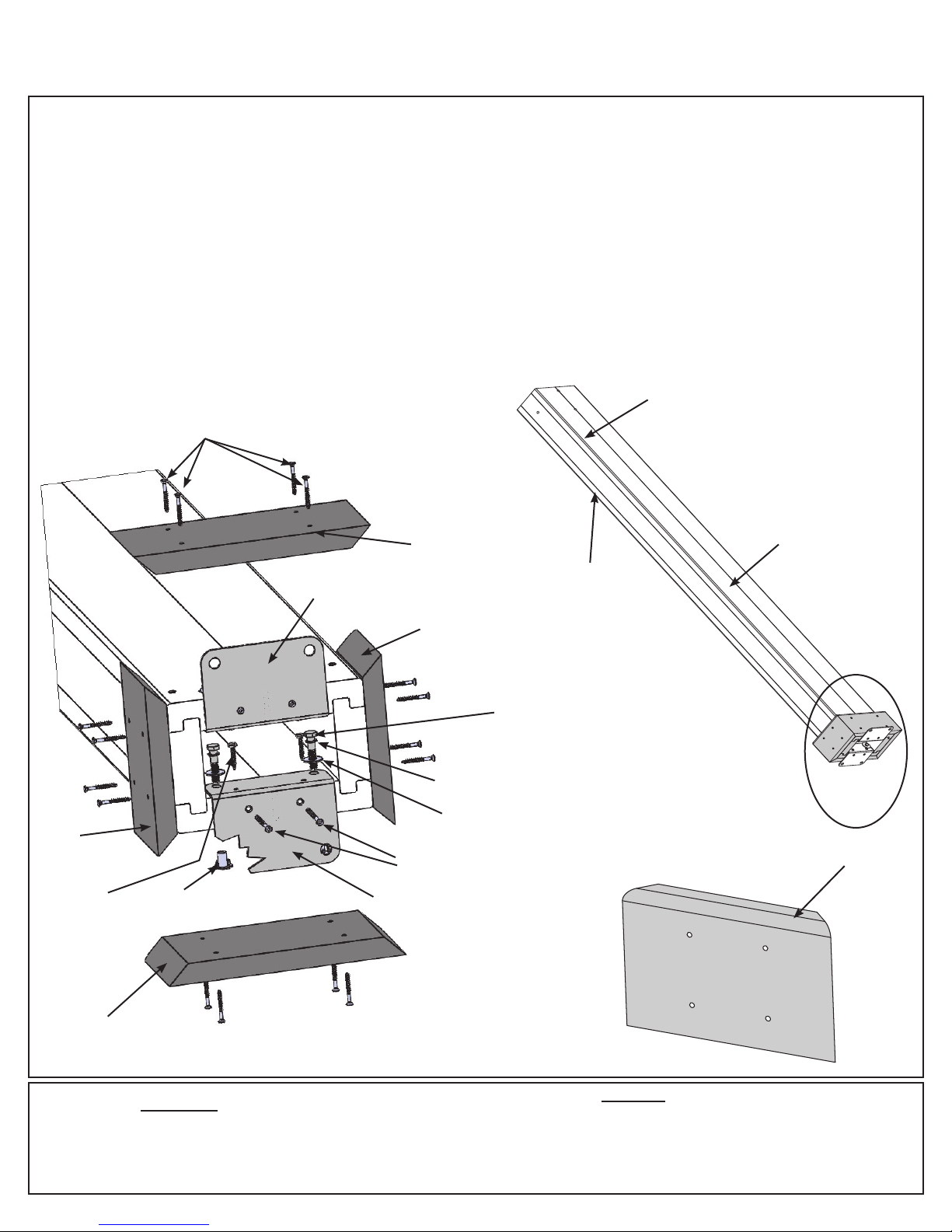
Step 2: Post Assemblies
A: At the bottom of one (621) 6 x 9 Post insert two 5/16” T-Nuts on the outside of each long side. (g. 2.2)
B: At the bottom of the same (621) 6 x 9 Post place two Post Mounts tight to the bottom and inside faces on the
long sides as shown in g. 2.1 and 2.2. Loosely attach with two 5/16 x 1-1/2” Hex Bolt (with 5/16” lock washer
and 1/4-5/16” large washer) per mount so they connect to the T-Nuts. From the bottom attach with two #8 x 2-1/2”
Wood Screws and two #10 x 1-1/4” Pan Screws per mount. Tighten bolts.
C: Flush to the bottom of (621) 6 x 9 Post place one (460) Plinth Long on each long side and one (459) Plinth on
each short side and attach with four #8 x 1-1/2” Wood Screws per plinth. Rounded edges on top. (g. 2.1, 2.2
and 2.3)
D: Repeat Steps A - C three more times to make four Post Assemblies.
Fig. 2.2
(459)
Plinth
#10 x 1-1/4”
Pan Screws
(x 2 per Post
Mount, from
inside)
#8 x 1-1/2”
Wood Screws
(x 4 per Plinth)
5/16” T-Nut (x 4
per Post)
Post
Mount
Top
(460)
Plinth
Long
(459)
Plinth
5/16” Lock
Washer
1/4 - 5/16”
Large Washer
#8 x 2-1/2” Wood Screws
(x 2 per Post Mount, from
outside)
Post Mount
(621) 6 x 9 Post
Short
Side
5/16 x 1-1/2” Hex Bolt
(x2 per Post Mount,
from inside)
Fig. 2.1
Fig. 2.3
Long
Side
Bottom
Rounded
Edge on Top
(460)
Plinth
Long
Wood Parts
4 x (621) 6 x 9 Post
8 x (459) Plinth
8 x (460) Plinth Long
15 support@yardistrystructures.com
16 x #8 x 2-1/2” Wood Screw
64 x #8 x 1-1/2” Wood Screw
16 x #10 x 1-1/4” Pan Screw
8 x Post Mount
Hardware
16 x 5/16” T-Nut
16 x 5/16 x 1-1/2” Hex Bolt
(with 5/16” lock washer, 1/4 - 5/16” large washer)
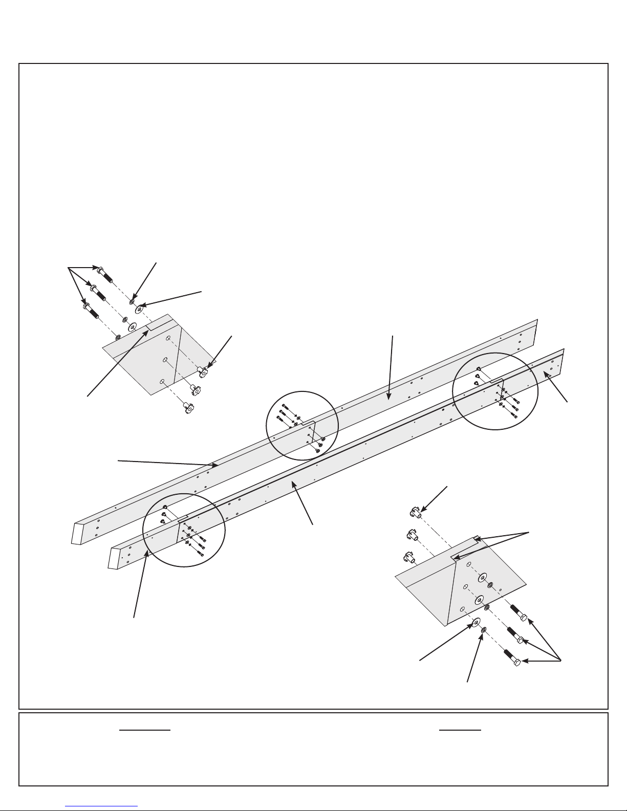
Step 3: Short Beam Assembly
Part 1
A: Connect one (660) Left Beam Short and one (661) Right Beam Short using three 5/16 x 1-1/2” Hex Bolts (with
5/16” lock washer, 1/4-5/16” large washer and 5/16” t-nut) as shown in g. 3.1 and 3.2. Notice orientation of bolt
heads.
B: Connect one (665) End Short Beam to each end of one (664) Centre Beam Short using three 5/16 x 1-1/2”
Hex Bolts (with 5/16” lock washer, 1/4-5/16” large washer and 5/16” t-nut) per end as shown in g. 3.1 and 3.3.
Notice orientation of bolt heads.
C: Repeat Steps A and B one more time to make two Short Beam L-R Assemblies and two End Short Beam
Assemblies.
5/16” Lock
5/16 x 1-1/2”
Hex Bolt
Washer
1/4-5/16”
Large Washer
Fig. 3.1
Fig. 3.2
Tight
(661) Right
Beam Short
5/16” T-nut
(664) Centre
Beam Short
(660) Left
Beam Short
(665) End
Short Beam
5/16” T-nut
Tight
Fig. 3.3
(665) End
Short Beam
Make sure bolt heads
are on the outside of
each Beam Assembly
2 x (664) Centre Beam Short
4 x (665) End Short Beam
2 x (660) Left Beam Short
2 x (661) Right Beam Short
16 support@yardistrystructures.com
1/4-5/16”
Large Washer
5/16” Lock
Washer
HardwareWood Parts
18 x 5/16 x 1-1/2” Hex Bolt
(5/16” lock washer, 1/4-5/16” large washer, 5/16” t-nut)
5/16 x
1-1/2”
Hex Bolt

Step 3: Short Beam Assembly
Part 2
D: Place one Short Beam L-R Assembly and one End Short Beam Assembly together so the beam assembly
ends are ush and the angled ends match. Bolt heads must be on the outside of both beam assemblies. Match
the bolt holes in each assembly then loosely attach with four 5/16 x 3” Hex Bolts (with 5/16” lock washer, 1/4-
5/16” large washer and 5/16” t-nut) in the top holes. (g. 3.4 and 3.5)
E: Secure assemblies with 18 #8 x 2-1/2” Wood Screws then tighten bolts. (g. 3.4)
F: Repeat Step D and E one more time to make two Short Beam Assemblies.
Short Beam L-R
Assembly
Fig. 3.4
Flush
Flush
End Short
Beam
Assembly
Fig. 3.5
Short Beam
L-R Assembly
5/16 x 3”
Hex Bolt
#8 x 2-1/2” Wood
Screws (x 18 per
assembly)
5/16” Lock
Washer
1/4-5/16”
Large Washer
End Short
Beam
Assembly
Use the
top holes
Hardware
36 x #8 x 2-1/2” Wood Screw
8 x 5/16 x 3” Hex Bolt
(5/16” lock washer, 1/4-5/16” large washer, 5/16” t-nut)
17 support@yardistrystructures.com
5/16”
T-nut
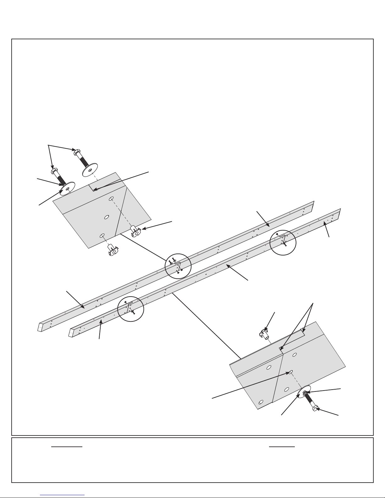
Step 4: Long Beam Assembly
Part 1
A: Connect one (649) Outer End Right and one (650) Outer End Left using two 5/16 x 1-1/2” Hex Bolts (with
5/16” lock washer, 1/4-5/16” large washer and 5/16” t-nut) as shown in g. 4.1 and 4.2. Notice orientation of bolt
heads.
B: Connect one (656) Inside Beam to each end of one (653) Inside Long Beam using two 5/16 x 1-1/2” Hex Bolts
(with 5/16” lock washer, 1/4-5/16” large washer and 5/16” t-nut), in the middle holes, as shown in g. 4.1 and 4.3.
Notice orientation of bolt heads.
C: Repeat Steps A and B to make two Outer Beam Assemblies and two Inside Beam Assemblies.
5/16 x 1-1/2”
Hex Bolt
5/16” Lock
Washer
1/4-5/16”
Large Washer
(649) Outer
End Right
Fig. 4.2
Outer Beam
Assembly
Tight
Fig. 4.1
(650) Outer
End Left
5/16”
T-nut
(656) Inside
Beam
(653 Inside
Long Beam
Tight
5/16” T-nut
Fig. 4.3
Inside Beam
Assembly
(656) Inside
Beam
5/16” Lock
Make sure bolt heads are
on the sides as shown
for each Beam Assembly
2 x (649) Outer End Right
2 x (650) Outer End Left
2 x (653) Inside Long Beam
4 x (656) Inside Beam
18 support@yardistrystructures.com
Use the
middle hole
1/4-5/16”
Large Washer
HardwareWood Parts
8 x 5/16 x 1-1/2” Hex Bolt
(5/16” lock washer, 1/4-5/16” large washer, 5/16” t-nut)
Washer
5/16 x 1-1/2”
Hex Bolt
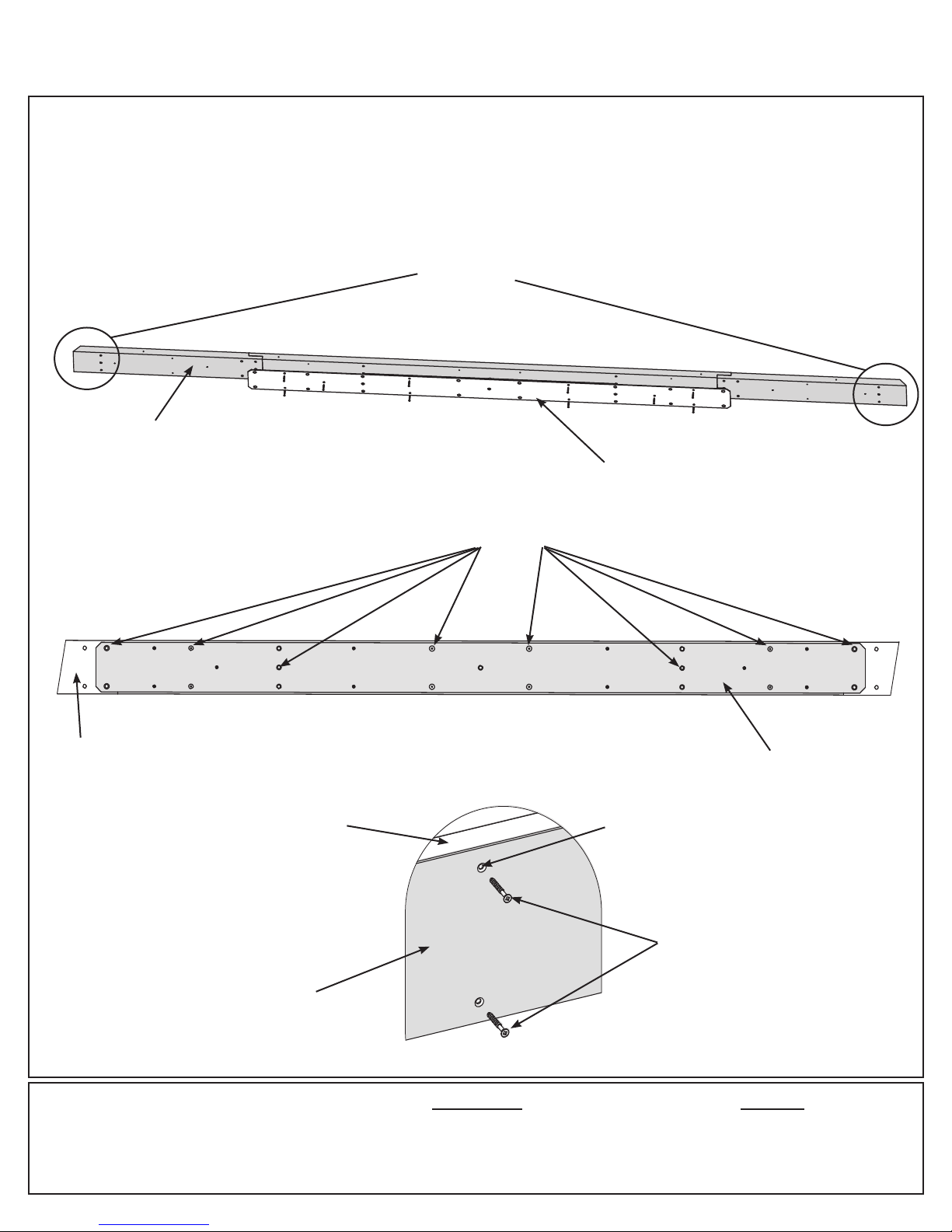
Step 4: Long Beam Assembly
Part 2
D: Place one Long Beam Insert centred on the inside of one Inside Beam Assembly (t-nut side). Match the bolt
holes in the Inside Beam Assembly and Long Beam Insert then attach with ten #7 x 3/4” Wood Screws. (g. 4.4,
4.5 and 4.6)
E: Repeat Step D for the second Inside Beam Assembly.
Notice orientation
Fig. 4.4
Inside Beam
Assembly
of angled ends
Long Beam
Insert
Fig. 4.5
Inside Beam
Assembly
Inside Beam
Assembly
Fig. 4.6
Long
Beam
Insert
Match bolt
holes
Long Beam
Insert
Notice countersink
holes are on the
screw side
#7 x 3/4”
Wood Screw
Components:
2 x Long Beam Insert
19 support@yardistrystructures.com
20 x #7 x 3/4” Wood Screw
Hardware
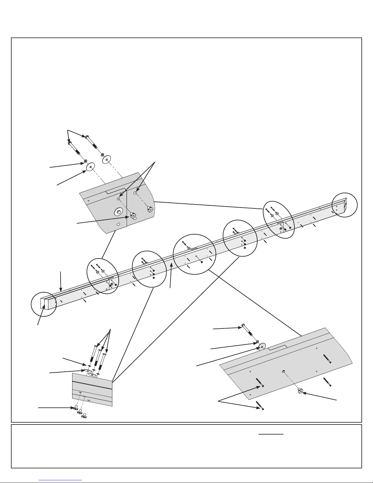
Step 4: Long Beam Assembly
Part 3
F: Place one Outer Beam Assembly and one Inside Beam Assembly together so the beam assembly ends are
ush and the angled ends match. Bolt heads must be on the outside of both beam assemblies. Match the bolt
holes in each assembly then loosely attach with eleven 5/16 x 3” Hex Bolts (with 5/16” lock washer, 1/4-5/16”
large washer and 5/16” t-nut). The bolts at each end must go in the top holes. (g. 4.7, 4.8, 4.9 and 4.10)
G: Secure assemblies with 16 #8 x 2-1/2” Wood Screws then tighten bolts. (g. 4.7 and 4.9)
H: Repeat Step F and G to make a second Long Beam Assembly.
5/16 x 3”
Hex Bolt
Fig. 4.8
Use the
5/16” Lock
Washer
1/4-5/16”
Large Washer
top holes
Notice orientation
of angled ends
Fig. 4.7
Outer Beam
Assembly
Flush
5/16” Lock
Washer
1/4-5/16”
Large Washer
5/16”
T-nut
5/16”
T-nut
Fig. 4.10
5/16 x 3”
Hex Bolt
Inside Beam
Assembly
1/4-5/16”
Large Washer
#8 x 2-1/2” Wood
Screws (x 16 per
assembly)
Fig. 4.9
5/16 x 3”
Hex Bolt
5/16” Lock
Washer
5/16”
T-nut
Hardware
32 x #8 x 2-1/2” Wood Screw
22 x 5/16 x 3” Hex Bolt
(5/16” lock washer, 1/4-5/16” large washer, 5/16” t-nut)
20 support@yardistrystructures.com
 Loading...