

Page 1
insert image here
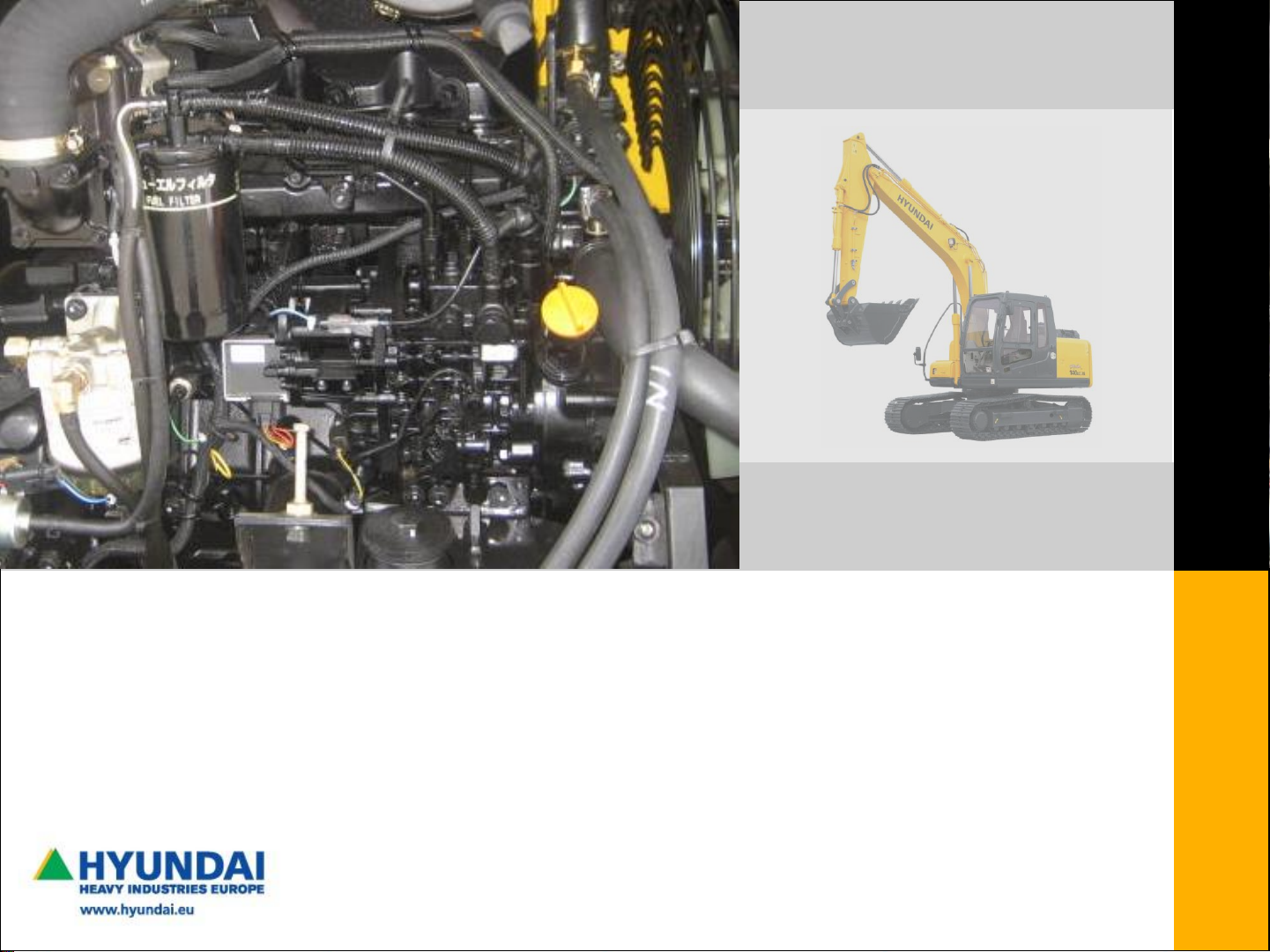
YANMAR 4TNV, Elec.Control.Governor (Tier III)
We build a better future
ENGINE TRAINING
for R55-7A, R55W-7A, R80-7A
EDITOR
PIETER EVERAERTS
R55-9, R55W-9, R60CR-9, R80CR-9
aug. 2012
Page 2
CONTENT
PAGE
1] GENERAL 03
2] ELECTRONIC CONTROL SYSTEM (ECO) 06
3] INJECTION PUMP 10
4] EXHAUST GAS RECIRCULATION (EGR) 43
5] COOLANT TEMP SENSOR 45
6] ELECTRICS 47
7] ENGINE VIEW 51
8] ENGINE ERROR CODE SYSTEM 52
9] YANMAR DIAGNOSTIC TOOL 58
10] FUEL PUMP ADJUSTMENT & &REPLACEMENT 61
PAGE
- 2 -
Related manuals:
TNV-ECO-manual.pdf (>Ceres : TNV-SERIES-ECM, part 1)
TNV-ECO-diagnostic tool.pdf (>Ceres : TNV-SERIES-ECM, part 2)
TNV-ECO-troubleshooting.pdf
TNV-INJ-mechanical.pdf (>Ceres: YANMAR FUEL INJECTION)
TNV-service-mechanical.pdf (>Ceres: YANMAR 3TNV, 4TNV)
HHIE TRAINING CENTRE
Hyundai Heavy Industries Europe
Vossendaal 11
2440 Geel - Belgium
Tel 0032 (0)14 56 22 00
Fax 0032 (0)14 56 22 65
Arranged by Pieter Everaerts
Instructor HHIE
Tel 0032 (0)14 56 22 44
Fax 0032 (0)14 56 22 65
Page 3
YANMAR R55(W)-7 R80-7 R55(W)-7A R80-7A
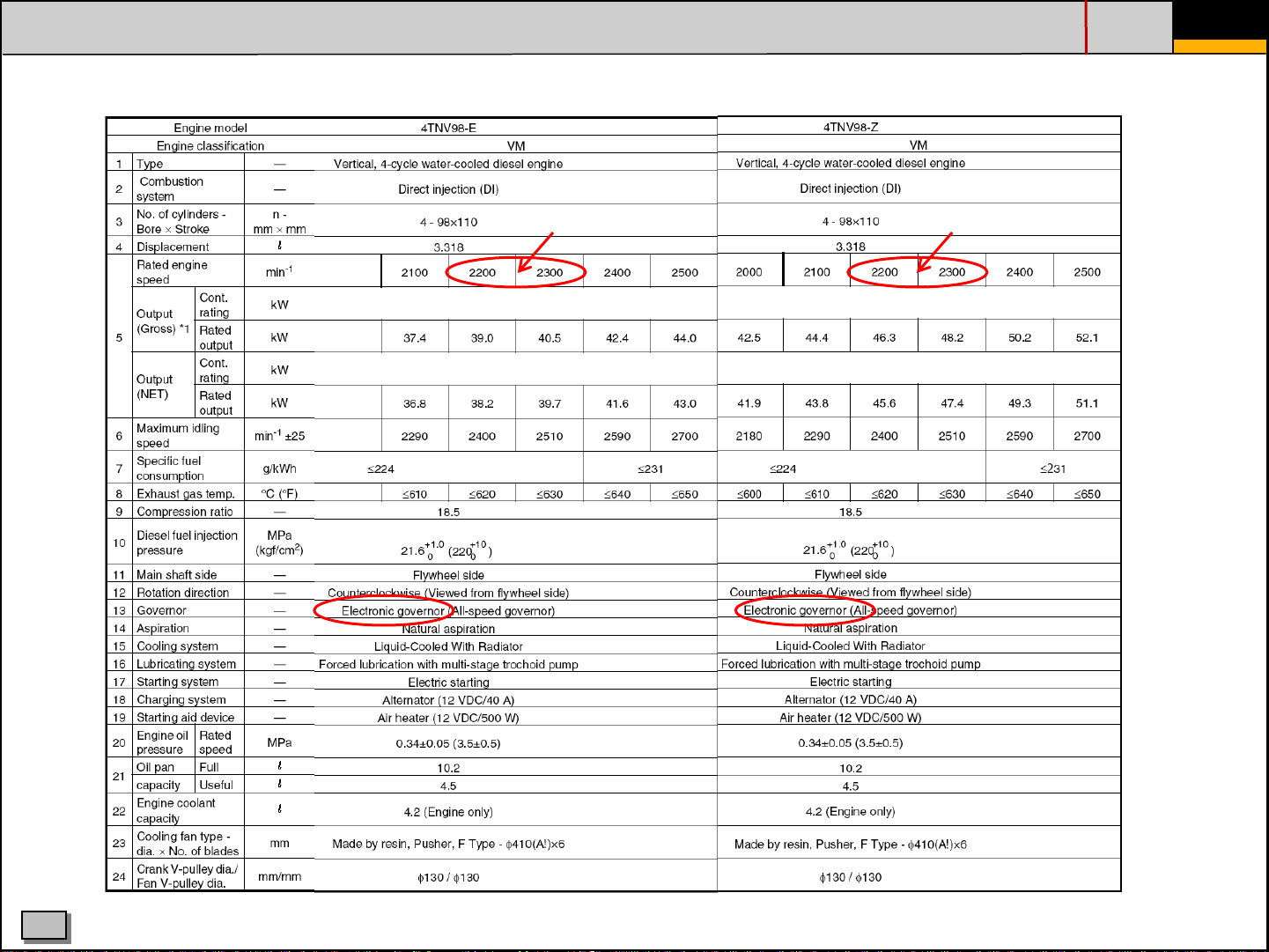
Engine model 4TNV94L 4TNV98
4TNV98-EPHYB 4TNV98-ZVHYB
Content / HP (Rated Gross) at rpm 3054cc / 53HP at 2200 rpm 3318cc / 60HP at 2100 rpm 3319cc / 57HP at 2400 rpm 3319cc / 59.6HP at 2100 rpm
Max. Torque at RPM 20.6 kgf at 1400 rpm 25.2 kgf at 1000 rpm 20.5 kgf at 1550 rpm 24.5 kgf at 1000 rpm
SETTING MAX RPM 2300±50 (R55-7) 2250±50 2260±50 2250±50
2400±50 (R55W-7) ("M" mode selected) ("H" mode selected)
1. GENERAL - OVERVIEW
PAGE
- 3 -
(All listed engines are Yanmar "NV3-Series engines" >> Range 3000...4000cc: all direct injection)
# cyl
cyl bore (mm)
derating output
eco -eng.)
Explanation of engine model names (-7A/-9)
E or Z stands for kind of output
P, V rated eng. speed
HY Hyundai
B excavator
-9 Series same engines
-7A "adapted technologie" to meet Tier III
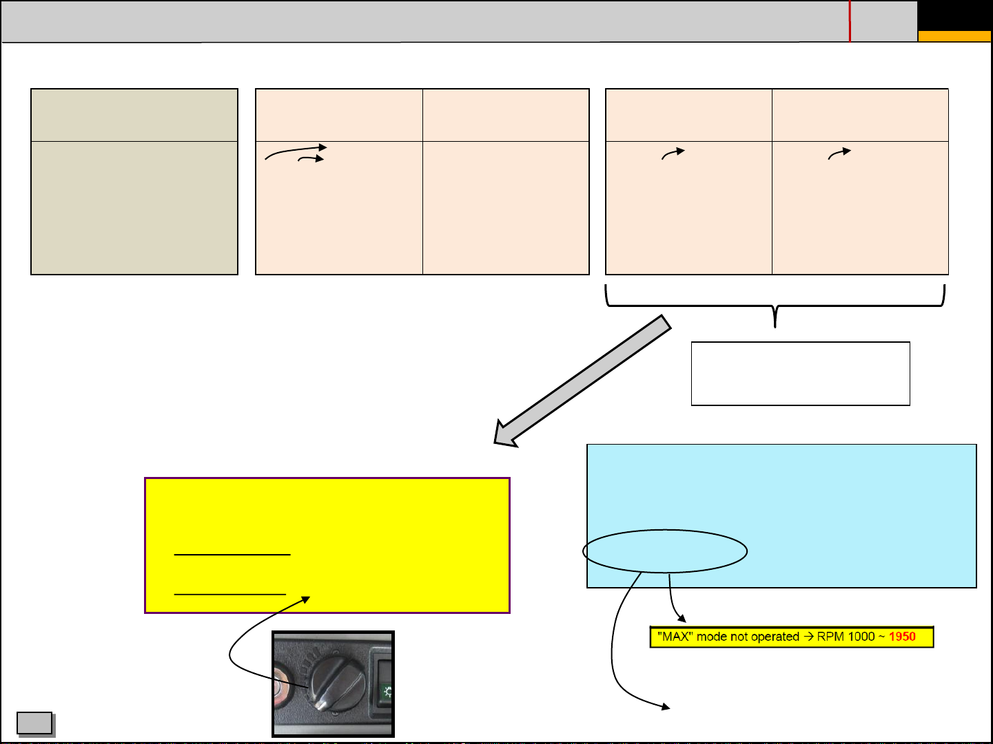
High idle Low idle eng. type
(M mode)
(higher fuel injection pressure)
R55-9 2200±30 1000±30 4NTV98-EPHYBU
R55W-9 2200±50 1050±100 4NTV98-EPHYBU
Electric Control of Exhaust Gas Regulation
Electric Control of Governor (= "ECO")
R60CR-9 2200±50 1000±50 4NTV98-EPHYBU
R80CR-9 2100±50 1000±50 4NTV98-ZVHYB
standard output
eco -eng.)
C
HHIE TRAINING CENTRE
At full charge,
eng. drop is max “150 rpm”
Page 4
1. GENERAL - SPECIFICATION
PAGE
- 4 -
R55(W)-7A R80-7A
2260 2250
C
HHIE TRAINING CENTRE
Page 5
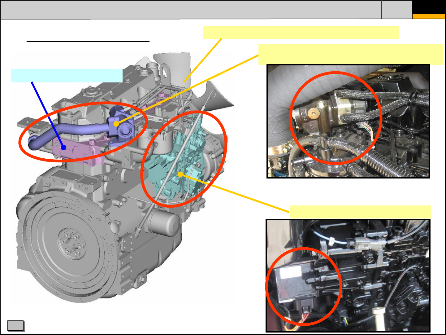
1. GENERAL - ENGINE LAY-OUT
PAGE
- 5 -
NV3, adapted (tier III)
Cylinder head with 4 valves
Optimization of injection bore diameter→Reduce PM
Electronic control of EGR (exhaust gas recirculation)
to achieve lower NOx
Electronic Control of Governor (ECO)
C
HHIE TRAINING CENTRE
Page 6
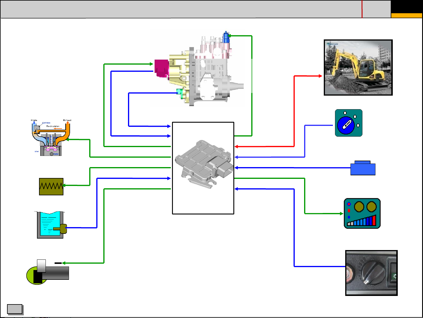
2. ELECTRONIC CONTROL SYSTEM (ECO)
PAGE
- 6 -
EGR
Air heater
Actuator
Rack position
sensor
Engine speed sensor
Electronic
control
governor
CSD valve (cold start device)
Fuel
injection pump
ECU
CAN
OFF
ON
START
Key switch
Switch
Coolant temp. sensor
Starter
C
Display
Accelerator
HHIE TRAINING CENTRE
Page 7
2. ELECTRONIC CONTROL SYSTEM ECO GOVERNOR
PAGE
- 7 -
C
HHIE TRAINING CENTRE
Page 8
2. ELECTRONIC CONTROL SYSTEM ECO GOVERNOR
PAGE
- 8 -
C
HHIE TRAINING CENTRE
Page 9
2. ELECTRONIC CONTROL SYSTEM 2G ECO GOVERNOR
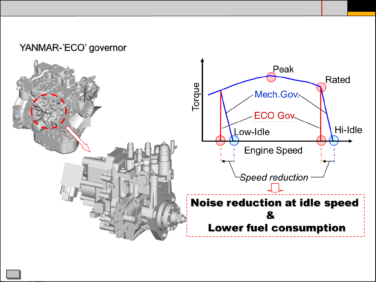
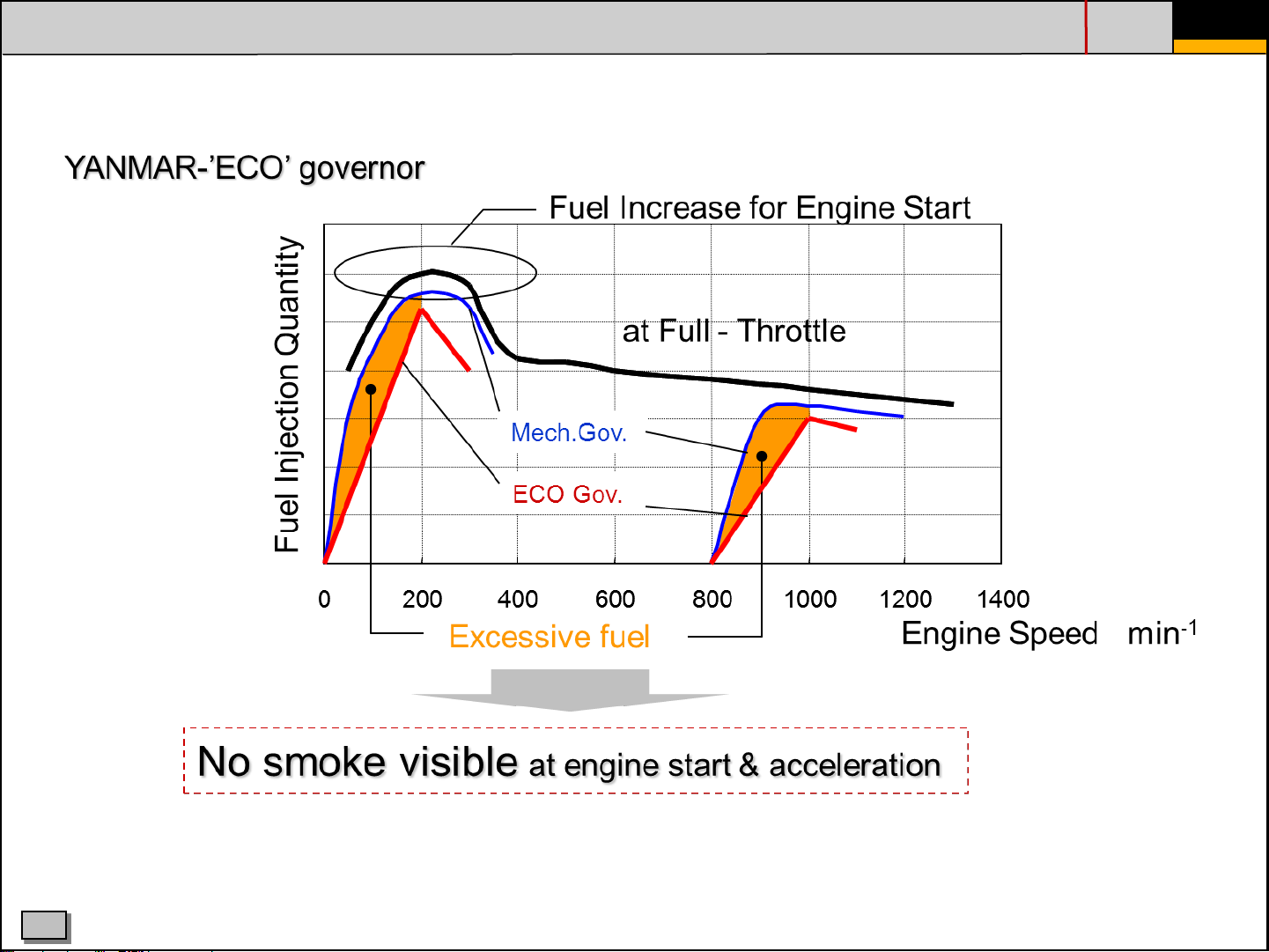
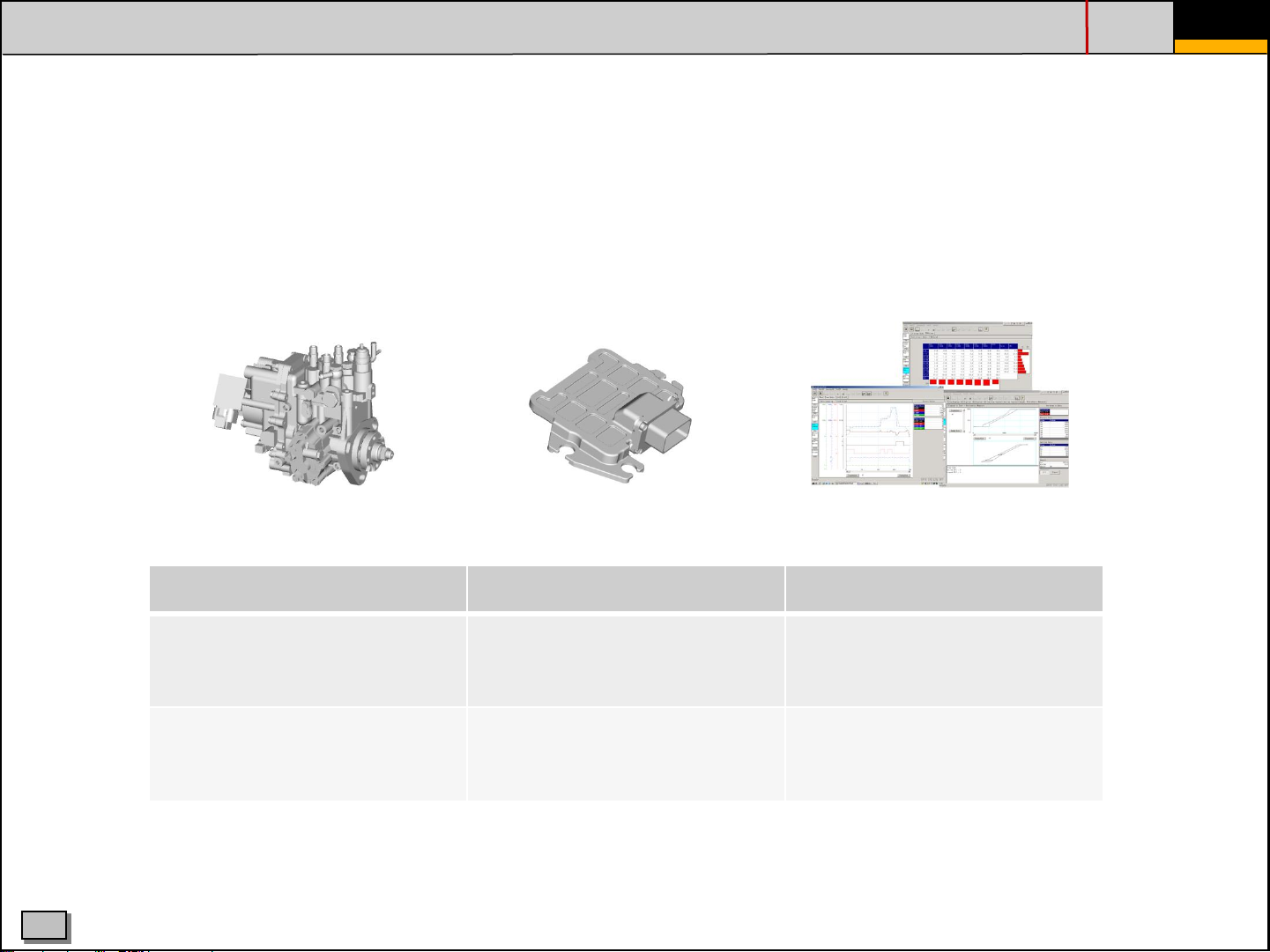
Eco-Governor is Yanmar’s unique electronics control governor system which has been
used for over 10 years mainly on agricultural machines. Yanmar has renewed this
system to aplly to all equipment and named it “2G Eco-Governor” which means second
generation Eco-Governor. In addition an EGR valve is controlled by this system.
PAGE
- 9 -
C
Idling speed control After heat control Communication function
Idling speed will be adjusted
depending on cooling water
temperature
Engine warm-up time reduced,
protection at high idle & less
white smoke
Starting aid devices stay
activated after start
HHIE TRAINING CENTRE
Data logging by ECO system
Connection for troubleshooting
Possible to monitor engine
performance
System diagnosis incl history
Page 10
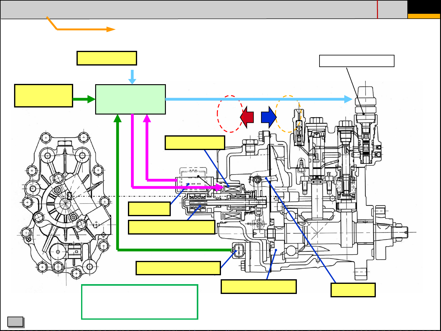
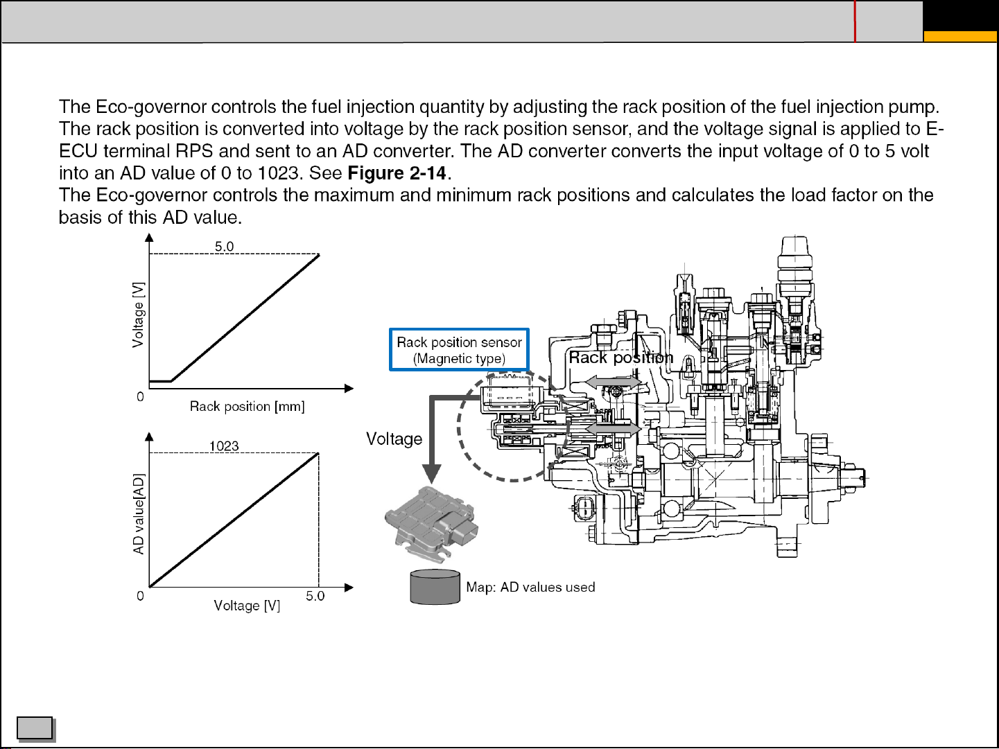
3. INJECTION PUMP - RACK CONTROL
Electronically control rack by ECU
PAGE
- 10 -
Target
engine speed
Water Temp.
ECU
Actuator force
Actuator
Rack act.
Rack position sensor
Fuel
+
Solenoid valve CSD
Spring return
Fuel
-
C
Engine speed sensor
when replacing the pump, data files
need to be written to the ECU>> See
"TNV-ECO-diagnostic tool.pdf, p51
for more information
HHIE TRAINING CENTRE
Engine speed gear
Rack
Page 11
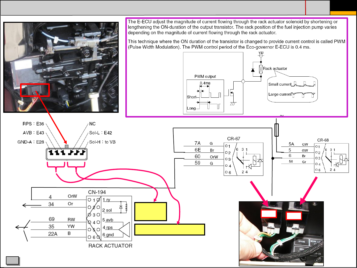
3. INJECTION PUMP - RACK CONTROL
PAGE
- 11 -
ECU
pin
nr. 42
12V fuse ECU
to ECU (pin 42)
(neg. control)
to ECU
C
6 5 4 3 2 1
Rack
actuator
Rack position sensor
HHIE TRAINING CENTRE
Relay
rack actuator
CR67
Relay
ECU Main
Power
CR68
Page 12
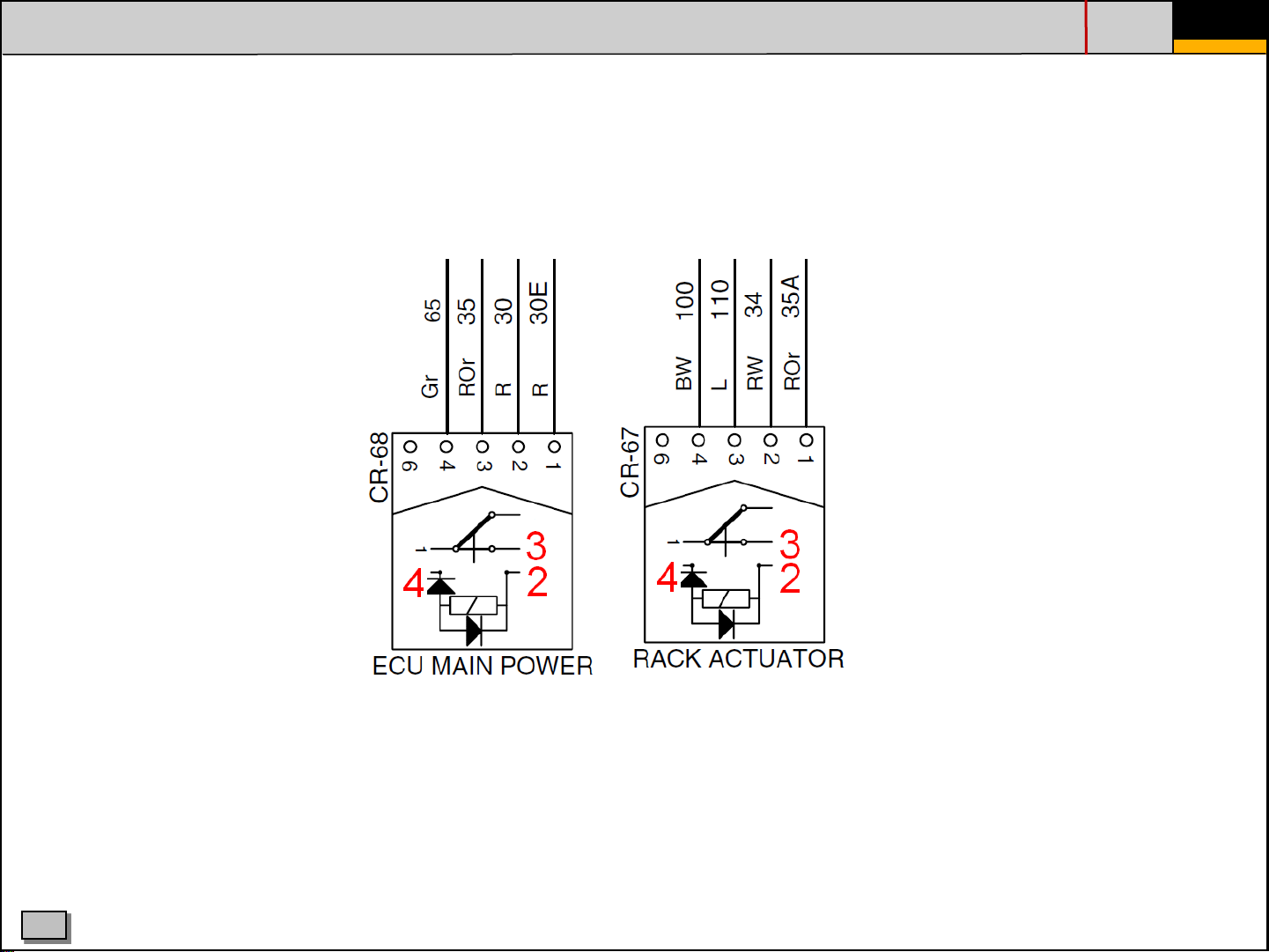
3. INJECTION PUMP - RACK CONTROL
CORRECTED PIN LAY OUT FOR CR-68 (ecu main power) AND CR-67 (rack actuator) ON R80-7A
PAGE
- 12 -
C
HHIE TRAINING CENTRE
Page 13
3. INJECTION PUMP - RACK POSITION SENSOR
PAGE
- 13 -
C
HHIE TRAINING CENTRE
Page 14
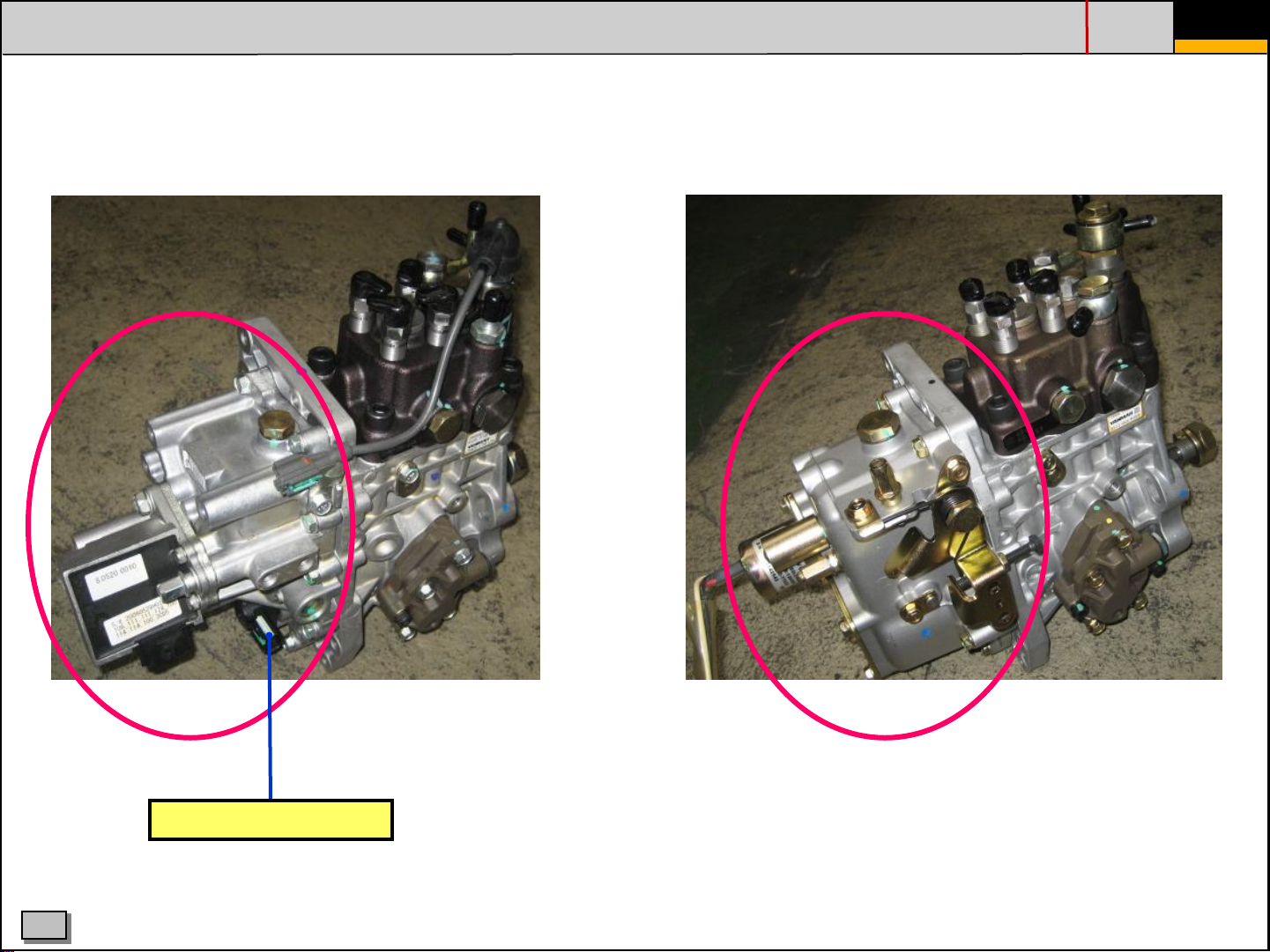
3. INJECTION PUMP - ECO 2G GOVERNOR VERSUS MECHANICAL GOVERNOR
INJ. PUMP WITH EL. GOVERNOR (on -7A & -9) INJ. PUMP WITH MECHANICAL GOVERNOR (on -7)
PAGE
- 14 -
C
Engine speed sensor
• magnetic type
• detects eng. speed with 12 pulsers attached
to the camshaft
HHIE TRAINING CENTRE
Page 15
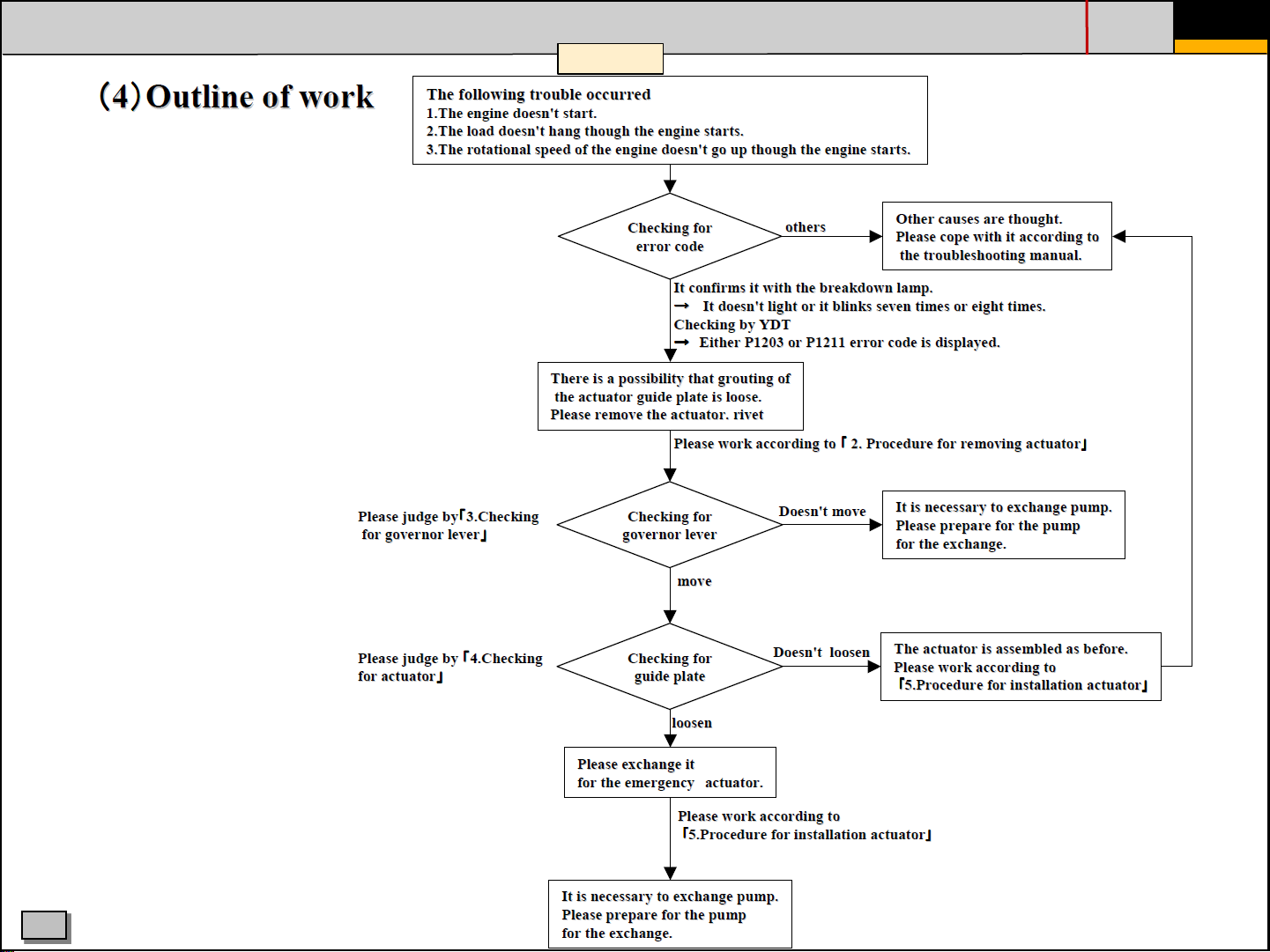
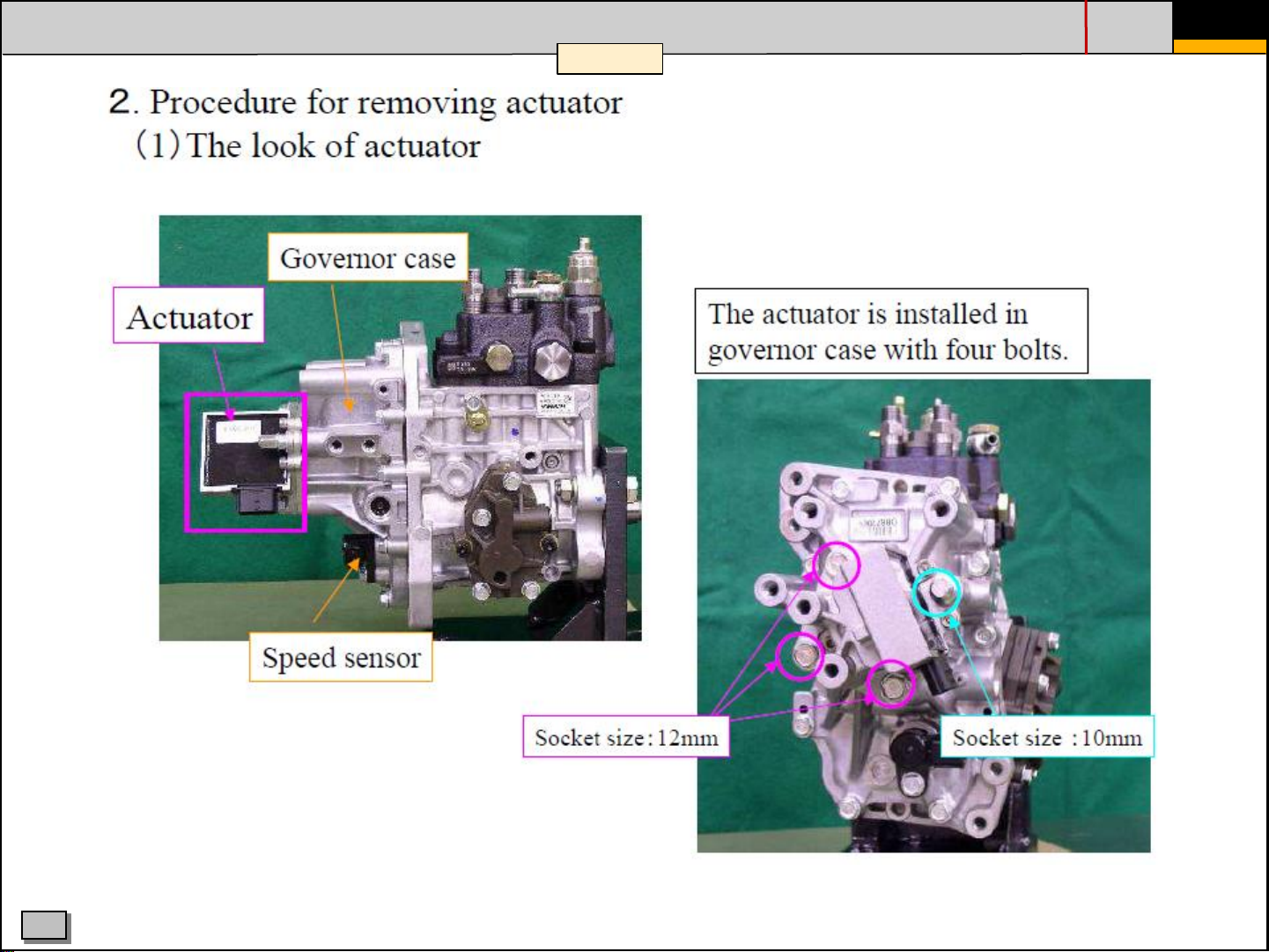
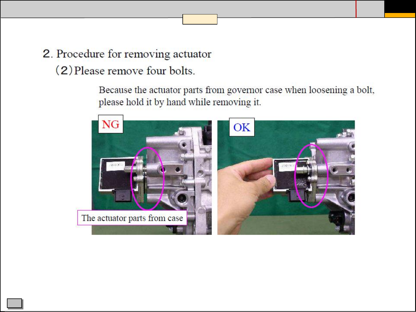
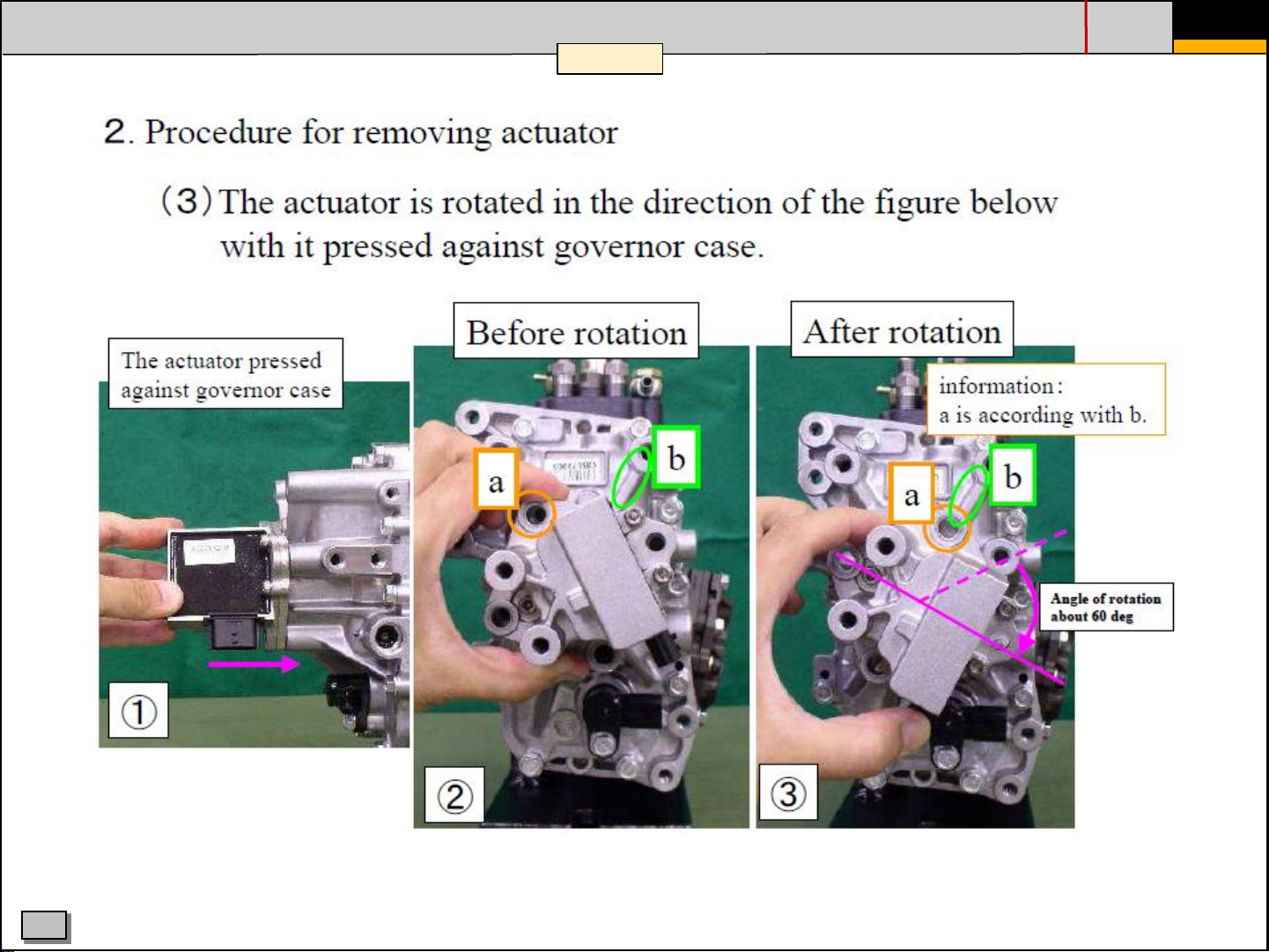
3. INJECTION PUMP - TROUBLESHOOTING FOR ACTUATOR & GOVERNOR-LEVER
1 / 19
PAGE
- 15 -
C
HHIE TRAINING CENTRE
Page 16
3. INJECTION PUMP - TROUBLESHOOTING FOR ACTUATOR & GOVERNOR-LEVER
2 / 19
PAGE
- 16 -
C
HHIE TRAINING CENTRE
Page 17
3. INJECTION PUMP - TROUBLESHOOTING FOR ACTUATOR & GOVERNOR-LEVER
3 / 19
PAGE
- 17 -
C
HHIE TRAINING CENTRE
Page 18
3. INJECTION PUMP - TROUBLESHOOTING FOR ACTUATOR & GOVERNOR-LEVER
4 / 19
PAGE
- 18 -
C
HHIE TRAINING CENTRE
Page 19
3. INJECTION PUMP - TROUBLESHOOTING FOR ACTUATOR & GOVERNOR-LEVER
5 / 19
PAGE
- 19 -
C
HHIE TRAINING CENTRE
Page 20
3. INJECTION PUMP - TROUBLESHOOTING FOR ACTUATOR & GOVERNOR-LEVER
6 / 19
PAGE
- 20 -
C
HHIE TRAINING CENTRE
Page 21
3. INJECTION PUMP - TROUBLESHOOTING FOR ACTUATOR & GOVERNOR-LEVER
7 / 19
PAGE
- 21 -
C
HHIE TRAINING CENTRE
Page 22

3. INJECTION PUMP - TROUBLESHOOTING FOR ACTUATOR & GOVERNOR-LEVER
8 / 19
PAGE
- 22 -
C
HHIE TRAINING CENTRE
Page 23

3. INJECTION PUMP - TROUBLESHOOTING FOR ACTUATOR & GOVERNOR-LEVER
9 / 19
PAGE
- 23 -
C
HHIE TRAINING CENTRE
Page 24

3. INJECTION PUMP - TROUBLESHOOTING FOR ACTUATOR & GOVERNOR-LEVER
10 / 19
PAGE
- 24 -
C
HHIE TRAINING CENTRE
Page 25

3. INJECTION PUMP - TROUBLESHOOTING FOR ACTUATOR & GOVERNOR-LEVER
11 / 19
PAGE
- 25 -
C
HHIE TRAINING CENTRE
Page 26

3. INJECTION PUMP - TROUBLESHOOTING FOR ACTUATOR & GOVERNOR-LEVER
12 / 19
PAGE
- 26 -
C
HHIE TRAINING CENTRE
Page 27

3. INJECTION PUMP - TROUBLESHOOTING FOR ACTUATOR & GOVERNOR-LEVER
13 / 19
PAGE
- 27 -
C
HHIE TRAINING CENTRE
Page 28

3. INJECTION PUMP - TROUBLESHOOTING FOR ACTUATOR & GOVERNOR-LEVER
14 / 19
PAGE
- 28 -
C
HHIE TRAINING CENTRE
Page 29

3. INJECTION PUMP - TROUBLESHOOTING FOR ACTUATOR & GOVERNOR-LEVER
15 / 19
PAGE
- 29 -
C
HHIE TRAINING CENTRE
Page 30

3. INJECTION PUMP - TROUBLESHOOTING FOR ACTUATOR & GOVERNOR-LEVER
16 / 19
PAGE
- 30 -
C
HHIE TRAINING CENTRE
Page 31

3. INJECTION PUMP - TROUBLESHOOTING FOR ACTUATOR & GOVERNOR-LEVER
17 / 19
PAGE
- 31 -
C
HHIE TRAINING CENTRE
Page 32

3. INJECTION PUMP - TROUBLESHOOTING FOR ACTUATOR & GOVERNOR-LEVER
18 / 19
PAGE
- 32 -
C
HHIE TRAINING CENTRE
Page 33

3. INJECTION PUMP - TROUBLESHOOTING FOR ACTUATOR & GOVERNOR-LEVER
19 / 19
PAGE
- 33 -
C
HHIE TRAINING CENTRE
Page 34

Temp coolant ≤ 5
at start
Temp coolant > 5
at
ACTIVATION:
CDS valve opens
(for
DISACTIVATION:
CDS valve closes
3. INJECTION PUMP - COLD START DEVICE (CSD)
PAGE
- 34 -
Solenoid valve CSD
Electric symbol
C
ECU
°C
HHIE TRAINING CENTRE
max. 5 min)
start
°C
Page 35

3. INJECTION PUMP - COLD START DEVICE (CSD)
PAGE
- 35 -
COLD START DEVICE on
YANMAR engine R55-7A
C
HHIE TRAINING CENTRE
Page 36

3. INJECTION PUMP - COLD START DEVICE (CSD)
PAGE
- 36 -
C
HHIE TRAINING CENTRE
Page 37

3. INJECTION PUMP - COLD START DEVICE (CSD)
PAGE
- 37 -
In case of CSD failure,
normaly only the solenoid
valve (1) needs to be
exchanged. All other parts
can remain in the FIP!
If other parts are or need to
be removed as well, the
easiest way to mount back is
shown in the next slides
C
HHIE TRAINING CENTRE
Page 38

3. INJECTION PUMP - COLD START DEVICE (CSD)
HOW TO RE-MOUNT PARTS OF CSD
PAGE
- 38 -
Mount the timer holder
C
Insert the timer spring
HHIE TRAINING CENTRE
Page 39

3. INJECTION PUMP - COLD START DEVICE (CSD)
PAGE
- 39 -
Insert the timer piston
(with some diesel for
lubrication)
C
HHIE TRAINING CENTRE
Page 40

3. INJECTION PUMP - COLD START DEVICE (CSD)
Insert the timer cap
PAGE
- 40 -
C
Timer cap installed
HHIE TRAINING CENTRE
Page 41

3. INJECTION PUMP - COLD START DEVICE (CSD)
Place the solenoid plunger
PAGE
- 41 -
C
And the solenoid spring
HHIE TRAINING CENTRE
Page 42

3. INJECTION PUMP - COLD START DEVICE (CSD)
PAGE
- 42 -
Finaly mount the solenoid
valve. Make sure that the
o-ring is mounted correct
as shown here. At
disassembly the o-ring
cán remain seated on the
solenoid plunger!
C
HHIE TRAINING CENTRE
Page 43

4. EXHAUST GAS RECIRCULATION (EGR)
Electric controlling
EGR
VALVE
ECU
goal of EGR valve:
PAGE
- 43 -
Speed & Load
& temp-coolant
Output
Electronic Control
for EGR valve
Intake Air
Exhaust Gas
combustion temp. reduction
NOx reduction
EGR principe:
By recirculating exhaust gases in the intake, the available gases to combust will be diminuished and that causes
slowing down & cooling of the combustion process by several hundred degrees, thus reducing NOx formation.
!! For electronically controlled EGR engine, it is necessary tu use fuel with max. 1000 ppm of sulfur !!! In
case of too much sulfur parts, sulfuric acid can be formed (due to the presence of recycled sulfur dioxide) and
cause corrosion on the cylinder liner and other major components
EGR domain
Engine Speed
C
HHIE TRAINING CENTRE
Page 44

4. EXHAUST GAS RECIRCULATION (EGR)
Output from ECU to EGR valve:
PAGE
- 44 -
Fig 2-22
C
EGR
VALVE
(A)
+12V
(A)
(B)
+12V
(B)
HHIE TRAINING CENTRE
Page 45

5. COOLANT(WATER) TEMP SENSORS CD-8 & CD-30
yanmar
PAGE
- 45 -
Hyundai
water temp. sensor
CD-30
(21EA-62010 for R55-7A )
C
Yanmar
water temp. sensor
CD-8
(XJAU-00896 for R55-7A)
HHIE TRAINING CENTRE
Page 46

5. COOLANT(WATER) TEMP SENSOR CD-8 (YANMAR )
PAGE
- 46 -
Voltage sig.
0.3 ~ 4.7 V
(HOT temp COLD temp)
C
Yanmar
water temp. sensor
CD-8
HHIE TRAINING CENTRE
Page 47

6a. LOCATION OF YANMAR ECU (& other electric components)
R55-7A
ENGINE
CONTROL
UNIT
R55-7A
DIAGNOSTIC PLUG
YANMAR CN 148
PAGE
- 47 -
ECU
RESISTOR RS-1
C
CR23
START
RELAY
CR24
AIR HEATER
RELAY
HHIE TRAINING CENTRE
Page 48

6a. LOCATION OF YANMAR ECU (& other electric components)
PAGE
- 48 -
R80CR-9 (first model)
VIEW BEHIND CAB
ECU
ENGINE CONTROL
UNIT
R80CR-9
(later model)
VIEW
RH SIDE OF CAB
ECU
C
DIAGNOSTIC PLUG
YANMAR CN148
HHIE TRAINING CENTRE
VIEW BEHIND CAB
ECU
R60CR-9
(later model)
Page 49

6b. STARTER CONTROL
Starter Control
Starter safety control
PAGE
- 49 -
Changeable(Option)
C
325 rpm
675 rpm
HHIE TRAINING CENTRE
Page 50

6c. ECU INPUTS & OUTPUTS
Eng. oil ps
Overheat lamp
(accel dial)
Find detailed info on ECU in/outputs:
in "elec-control-manual" p. 2-15/2-16-2-17
M-mode function
Eng. oil ps
Cluster
- 50 -
water temp
HYUNDAI
YANMAR
PAGE
C
Plug for
diagnose &
programming
to CDS
valve
HHIE TRAINING CENTRE
page 17
Page 51

7. ENGINE VIEW
Air cleaner SW
CD 10
CSD valve (Cold
start device) CD 62
EGR valve (Exhaust
Gas Recirculation)
CN 193
RACK
ACTUATOR
CN 194
Lift pump
CN 145
Water Temp
CD 8
(Yanmar)
Water Temp
CD 30
(Hyundai)
Pre heater
CN 80
Eng Oil
press CD 18
PAGE - 51 -
Tacho
(speed)
sensor
CD 17
C
Page 52

8a. ENGINE ERROR CODE SYSTEM -7A Series
When the ECU (engine control unit) detects an active engine fault,
the engine fault warning lamp on the cluster lights up and the beeper inside cluster starts beeping
Each engine fault code generates a specified amount of beeps with specified length:
Example 1
PAGE
- 52 -
LISTEN TO LENGTH &
FREQUENCE OF
BEEPS FOR
TROUBLESHOOTING !
“Accelerator engine failure” BEEPS CODE = “5”
In this case the beeper creates 5 “short” beeps
Example 2
“ERG valve failure” BEEPS CODE = “1 - 3”
In this case the beeper creates 1 “long” beep,
followed by 3 “short” beeps
In case of simultaneous engine faults, the different beep patterns will appear successively, in order of increasing number of beeps.
A complete overview of the engine errors list can be found on next pages
C
HHIE TRAINING CENTRE
Page 53

ENGINE ERROR CODES LIST
C
PAGE - 53 -
Number
of
beeps
Page 54

ENGINE ERROR CODES LIST
C
PAGE - 54 -
Number
of
beeps
Page 55

ENGINE ERROR CODES LIST
C
PAGE - 55 -
Number
of
beeps
Page 56

8b. ENGINE ERROR CODE SYSTEM -9 Series
PAGE
- 56 -
C
SEE FULL LIST ON NEXT PAGES
HHIE TRAINING CENTRE
Find more info about Hyundai error
codes & Cluster functioning in the
manual: “CLUSTER 5~8 ton exc.”
YANMAR
To visualise other fault
codes, use the buttons:
Page 57

8b. ENGINE ERROR CODE SYSTEM -9 Series
PAGE
- 57 -
C
HHIE TRAINING CENTRE
Page 58

9. YANMAR ENGINE DIAGNOSTIC TOOL (YEDST)
PAGE
- 58 -
PC Requirements PC/AT compatible
Part nr. of Yanmar Engine Diagnostic Tool : XJAU-01062
interface
USB cable
+ "CD"
cable to connect
in CN148
(diagn. plug)
Mind that some repair works (or others) can only be done by application
of the YEDST tool !
C
-replacing of pump
-calibrating of ECU
-tuning of engine
HHIE TRAINING CENTRE
ECU
Page 59

9. YANMAR ENGINE DIAGNOSTIC TOOL (YEDST) - EXTRACT
>> CONFIGURATION MENU (FOR REPLACE OF ECU, PUMP)
When you mount a new ECU, you need to copy the data from the injection
pump to the ECU: the data per injection pump is "individual " and "engine
specific.
PAGE
- 59 -
FULL INFO SEE
PAGES 44...48 OF
YEDST MANUAL
C
...
Pump data controller
...
...
HHIE TRAINING CENTRE
Page 60

9. YANMAR ENGINE DIAGNOSTIC TOOL (YEDST) - EXTRACT
When you mount a new injection pump, the data from this pump needs to
be written to the ECU: in that case the ECU is updated according to the
settings of the new pump
PAGE
- 60 -
☞
At page 50
of YEDST
manual
>> CALIBRATION MENU (YEDST)
(APS)
>> TUNING (YEDST)
C
HHIE TRAINING CENTRE
☞
☞
At page 51
of YEDST
manual
At page 52
of YEDST
manual
Page 61

10a. FUEL PUMP ADJUSTMENT
Before you adjust the pump timing make sure to
mark the current position! Also attach a mark
sticker on the engine next to the mark on the fuel
pump so you can measure how far you adjust the
fuel pump.
PAGE
- 61 -
C
HHIE TRAINING CENTRE
Page 62

10a. FUEL PUMP ADJUSTMENT
To be able to adjust the fuel pump you first have to loosen 7 bolts. 3 on the rear support and 4
on the flange at the distribution side. In red line you see the position of 2 of them behind the
pump house. These can be reached using a ¼, 14mm socket and extensions as shown in the
picture. The nuts and bolts don’t have to be removed just loosened.
PAGE
- 62 -
C
HHIE TRAINING CENTRE
Page 63

10a. FUEL PUMP ADJUSTMENT
The fuel pump can be tilted to advance or retard the fuel injection moment. To make this
possible the 7 bolts used to fixate the pump are provided with slotted holes.
PAGE
- 63 -
C
HHIE TRAINING CENTRE
Page 64

10a. FUEL PUMP ADJUSTMENT
To advance the fuel injection you have to turn clockwise when looking to the front of the
engine, the delay the fuel injection, turn counter-clockwise.
PAGE
- 64 -
C
HHIE TRAINING CENTRE
Page 65

10b. FUEL PUMP REPLACEMENT
If you like to replace the fuel pump you have to follow the previous steps but this time
completely remove the 7 mounting bolts on the pump and the support on the rear of the pump.
You also have to disconnect the fuel, oil & electric lines. Be carefull for high pressure when you
are disconnecting the fuel lines!
Proceed by removing the fuel pump drive gear cover. Then remove the center nut. NEVER
loosen the four flange bolts! They connect the fuel pump drive gear to the flange through slotted
holes. When they are loosened the fuel pump drive gear can rotate freely and all references of
timing will be lost!
PAGE
- 65 -
C
HHIE TRAINING CENTRE
Page 66

10b. FUEL PUMP REPLACEMENT
PAGE
- 66 -
Normally it is enough to put a mark on fuel pump drive gear
and idler to be able to reassemble the pump on the correct
position after removal. But when the injection pump was
mounted in the wrong position or the engine has rotated after
removal of the pump there is a more precise way to put
everything right on time.
On the crankshaft pully are 3 timing marks, 2 bulges and 1
notch. You have to align this notch to the 0° mark on the
distribution cover (TDC cyl.1), make sure that cyl 1 is not only
on his TDC but also on compression AND be able to see the
“B” mark on the idler in the middle (not to high or to low) of
the opening from the fuel pump driver cover. These 3
situations combined appear only once every !50! Crankshaft
revolutions so a little patience can be helpfull...
When you have the engine in this position you can align the
“B” mark on the fuel pump drive gear with the “B” mark of the
idler and the gears will be positioned perfectly.
C
HHIE TRAINING CENTRE
Page 67

10b. FUEL PUMP REPLACEMENT
PAGE
- 67 -
If you replace the pump you have to calculate the injection timing difference between these pumps:
1) Remove the old pump and take a note of the timing index recorded in that pump.
2) Read the timing on the new pump and calculate the difference between new and old angle.
3) Put the pump temporarily on the gear case and install the drive gear accordingly to the ID marks you
made earlier. (Tightening torque of installation nut => 113 – 123 Nm)
4) Use the marking on the sticker to adjust the calculated (2) injection angle difference.
5) If you have calculated a positive angle correction value, push the fuel pump away from the cylinder block
to delay the injection timing and vice versa to advance the timing in case of a negative value.
C
HHIE TRAINING CENTRE
Page 68

10b. FUEL PUMP REPLACEMENT
If there is no timing index on the pump body
you can find it in this table buy using the
pump ID number.
PAGE
- 68 -
C
HHIE TRAINING CENTRE
Page 69

END
PAGE
- 69 -
C
HHIE TRAINING CENTRE
 Loading...