

Page 1

OPERATOR'S MANUAL
COMPACT TRACTOR
Lx Series
Lx410
Lx450
Lx490
Version 1.0
Code No.:0A042-U00400
ENGLISH
Yanmar America Corporation
101 International Pkwy
Adairsville, GA 30103
PRINTED IN U.S.A.
Page 2
IMPORTANT
Pursuant to California Public Resources Code
Section 4442.6
WARNING - Operation of This Equipment May
Create Sparks That Can Start Fires Around Dry
Vegetation. A Spark Arrestor May be Required. The
Operator Should Contact Local Fire Agencies For
Laws or Regulations Relating to Fire Prevention
Requirements.
1A8250-65390
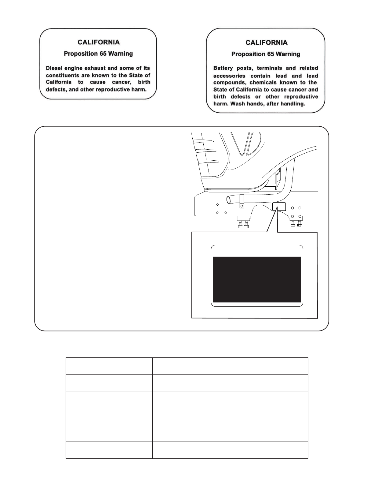
NOTE
●The following decal is applicable only for Lx410 and
Lx450.
Operator's Record
Owner's Name
IMPORTANT
Pursuant to California Public Resources
Code Section 4442.6
WARNING - Operation Q f This Equipment
May Create Sparks That Can Start
Fires Around Dry Vegetation. A Spark
Arrestor May be Required. The Operator
Should Contact Local Fire Agencies
For Laws or Regulations Relating to
Fire Prevention Requirements.
1A8250-65390
Owner's Address
Owner's Phone Number
Dealer/Seller Name
Dealer/Seller Address
Dealer/Seller Phone Number
Page 3

INTRODUCTION
Welcome to the World of Yanmar Tractor
Thank you for purchasing Yanmar tractor product that has been designed and
manufactured based on the Yanmar state-of-the-art technology and rich
expertise in developing and manufacturing products.
Handle the tractor correctly by following the instructions in the Operator's Manual
so that the tractor will provide long years of reliable and predictable service.
The Operator's Manual constitutes an indispensable part of the Yanmar tractor
product. Always keep the Operator's Manual readily accessible.
Carefully study the Operator's Manual to get familiar with the instructions and
informations contained in the Operator's Manual. The instructions and
informations are helpful in using the tractor correctly and safely, avoiding
personal injury and other accidents during operation and servicing of the tr actor.
When using any implement together with the tractor, also carefully study the
Operator's Manual of the implement so that the operator can use the implement
safely, correctly and efficiently.
The Operator's Manual is organized with sections arranged in a particular order
so that the operator can better understand the safety messages and the controls
on the tractor to help the operator operate the tractor correctly and safely. The
Operator's Manual will also help the operator answer questions about operation
and servicing.
The tractor shown in the Operator's Manual may somewhat differ from the actual
tractor. The Operator's Manual will still assist the operator in understanding the
instructions associated with the tractor. Before delivery of the tractor, your
Yanmar Tractor dealer has performed a pre-delivery check to ensure that the
tractor can long remain problem free.
All information, descriptions, specifications, drawings, illustrations, and
pictures in this manual are based on the latest information available at the
time this manual was published. Yanmar reserves the right to make
changes at any time without prior notice.
© 2011 Yanmar Co., Ltd.
Yanmar licenses the usage rights of this manual in North America to
YANMAR AMERICA CORPORATION.
© 2011
1
Lx410/450/490 Operator’s Manual
Page 4

PICTOGRAPHS
To help assist the operator in operating the tractor, various easy to understand pictographs have been created
and are used throughout the Operator's Manual. The pictographs are listed below together with the
corresponding meanings.
<Starter key switch>
Safety alert symbol
Engine start
<Instrument panel>
Fuel level
Glow
Engine oil pressure
Alternator/Battery charging condition
Engine speed
Hour meter
Engine coolant temperature
Revolutions Per Minute (rpm)
Power Take Off (PTO)
Engine run
Engine shut-off
<Levers and knobs>
Power Take Off (PTO) OFF position
Power Take Off (PTO) ON position
Differential lock
Implement control lock/unlock
4-wheel drive on
2-wheel drive on
Slow
Fast
Parking brake
<Lights>
Turn signal
Headlight high
Headlight low
Hazard warning lights
Lx410/450/490 Operator's Manual
Position control raised position
Position control lowered position
Hydraulic flow control/stop
Tilt pedal lock/unlock
Parking brake lock/unlock
2
Page 5

TABLE OF CONTENTS
1. SAFETY PRECAUTIONS ................................................................................... 1-1
1. About The Operator’s Manual.................................................................................................1-1
2. Safety Alert Symbol................................................................................................................. 1-2
3. Precautions Before Operating The Tractor ............................................................................. 1-3
4. Safe Practices for Operating the Tractor................................................................................. 1-4
1. Start the Tractor................................... ..................................................................................................................1-4
2. Work with the Tractor ............................................................................................................................................1-5
3. Stop the Tractor...................................................................................................... ... ............................................1-5
4. Considerations for Safety of a Child......................................................................................................................1-5
5. Operate the Tractor on Slopes................................................................................................1-6
6. Travel on a Road .....................................................................................................................1-7
7. Safe Practices for Parking the Tractor .................................................................................... 1-7
8. Operate the Power Take Off (PTO).........................................................................................1-8
9. Use the 3-Point Hitch ..............................................................................................................1-8
10.Roll-Over Protective Structure (ROPS) Precautions............................................................... 1-8
11.Safe Practices for Servicing the Tractor..................................................................................1-9
12.Replace the Rubber Product/s, such as Hydraulic Hose, Fuel Hoses, Power Steering Hoses,
Radiator Hoses and Air Intake Hose for Every 2 Years........................................................1-11
13.Understand the Tractor Safety Decals..................................................................................1-11
Safety Alert Symbol.............................................................................................................................................1-11
Care of DANGER, WARNING and CAUTION Decals.........................................................................................1-11
2. SERVICE THE TRACTOR.................................................................................. 2-1
3. SPECIFICATIONS............................................................................................... 3-1
1. Specifications Table................................................................................................................ 3-1
2. Traveling Speeds ....................................................................................................................3-3
4. IMPLEMENT CAPACITIES................................................................................. 4-1
5. NAMES AND FUNCTIONS OF COMPONENTS................................................ 5-1
1. Overview .................................................................................................................................5-1
Names of Main Components.................................................................................................................................5-1
Functions of Main Components........... ... ... ............................................................................................................5-2
2. Operator Station Controls........................................................................................................ 5-3
Names of Components..........................................................................................................................................5-3
Function of Components .......................................................................................................................................5-4
3. Instrument Panel................................................................................................................... 5-13
6. PRE-OPERATION CHECK................................................................................. 6-1
1. Pre-Operation Check............................................................................................................... 6-1
2. Precautions Before Operation.................................................................................................6-1
3. Routine Checks.......................................................................................................................6-1
4. Prevent Damage to Plastic Surfaces and Painted Surfaces...................................................6-1
3
Lx410/450/490 Operator's Manual
Page 6

TABLE OF CONTENTS
7. OPERATE THE ENGINE .................................................................................... 7-1
1. Start the Engine....................................................................................................................... 7-1
2. Start the Engine in Cold Weather............................................................................................ 7-8
3. Shut Off the Engine.................................................................................................................7-8
4. Restart a Stalled Engine........................................................................................................ 7-10
5. Start When the Engine Runs Out of Fuel..............................................................................7-10
8. OPERATE THE TRACTOR................................................................................. 8-1
1. Operate a New Tractor............................................................................................................8-2
Always run the tractor at less than full speed during the first 50 hours of operation .............................................8-2
Change the lubricating oil for the new tractor........................................................................................................8-2
2. Raise and Lower the Roll-Over Protective Structure (ROPS)................................................. 8-3
Lower (folded "down") the Roll-Over Protective Structure (ROPS).......................................................................8-3
Raise (unfolded "up") the Roll-Over Protective Structure (ROPS) ........................................................................8-4
3. Operate the Tractor.................................................................................................................8-4
Headlights and Side Lights....................................................................................................................................8-5
Turn Signals .................................................................................. ... .....................................................................8-5
Hazard Lights ........................................................................................................................................................8-5
Forward/N/Reverse Lever .....................................................................................................................................8-5
Warm Up Transmission Hydraulic Oil in a Cold Weather Situation.......................................................................8-6
Primary Gear Lever ...................................................... ... ................................................ ... ...................................8-7
Range Gear Lever.................................................................................................................................................8-7
2WD/4WD Lever....................................................................................................................................................8-9
Tips on the 4-Wheel Drive ....................................... ........................................................ ... ...................................8-9
Throttle Control Lever..........................................................................................................................................8-10
Accelerator Pedal ................................................................................................................................................8-10
3-Point Hitch Control Lever .................................................................................................................................8-10
4. Stop the Tractor..................................................................................................................... 8-11
Stopping Procedure.......... .. ... ........................................................ ... ...................................................................8-11
Stop in an Emergency .........................................................................................................................................8-11
5. Use the Brake........................................................................................................................ 8-12
Engage the Parking Brake...................................................................................................................................8-12
Disengage the Parking Brake..............................................................................................................................8-12
Use the Brake Pedals as Driving Brake (on Roads)............................................................................................8-12
Use the Brake Pedal for Easier Turning..............................................................................................................8-13
Use the Clutch Pedal...........................................................................................................................................8-13
6. Practices for Safe Operation................................................................................................. 8-14
Differential Lock...................................................................................................................................................8-14
Drive the Tractor on Roads .................................................................................................................................8-14
Push or Tow the Tractor......................................................................................................................................8-15
Allowable Loads When Towing with the Tractor..................................................................................................8-16
Transport the Tractor on a Trailer............................................. ...........................................................................8-17
Operate on Slopes and Rough Terrain................................................................................................................8-17
Uphill and Downhill Slopes ..................................................................................................................................8-18
Steep Downhill Slope ..........................................................................................................................................8-18
About the Power Steering....................................................................................................................................8-19
Lx410/450/490 Operator's Manual
4
Page 7

TABLE OF CONTENTS
9. POWER TAKE OFF (PTO) SYSTEM.................................................................. 9-1
1. Operate the Power Take Off (PTO) System............................................................................9-1
Determine the Appropriate Power Take Off (PTO) Speed ....................................................................................9-2
Engage Power Take Off (PTO) (with the operator on the operator seat)..............................................................9-2
Disengage Power Take Off (PTO) (with the operator on the operator seat) .........................................................9-3
2. Use Power Take Off (PTO) Safely..........................................................................................9-3
Use Power Take Off (PTO) Shield ........................................................................................................................9-3
3. Install an Implement to Power Take Off (PTO) Driveline ........................................................ 9-4
10.3-POINT HITCH AND DRAWBAR.................................................................... 10-1
1. 3-Point Hitch ..........................................................................................................................10-1
Use the 3-Point Hitch Control Lever ....................................................................................................................10-1
Use the Position Stop Knob.................................................................................................................................10-2
Hydraulic Flow Control/Stop Knob.......................................................................................................................10-2
Use the Lower Links (and Top Link as Needed) .................................................................................................10-3
Level the Implement Front to Rear......................................................................................................................10-4
Level the Implement Side to Side........................................................................................................................10-4
Adjust the Stabilizer.............................................................................................................................................10-5
2. Drawbar................................................................................................................................. 10-5
Maximum Drawbar Loads....................................................................................................................................10-5
Deploy/Stow the Drawbar....................................................................................................................................10-6
3. Use the Safety Chain10-6
Remove Drawbar.................................................................................................................................................10-6
11.HYDRAULIC SYSTEM...................................................................................... 11-1
1. 3-point Hitch Control System.................................................................................................11-1
Use the 3-Point Hitch Control Lever ....................................................................................................................11-1
Use the Position Stop Knob.................................................................................................................................11-2
Hydraulic Flow Control/Stop Knob.......................................................................................................................11-2
2. Operate the Implement Control Valve................................................................................... 11-3
Implement Control Lever .................................................................. ...................................................................11-3
Implement Control Lever Lock.................................................. .. ... ......................................................................11-4
Connect the Implement Hydraulic Hoses ............................................................................................................11-4
12.TIRES, WHEELS AND WEIGHTS.................................................................... 12-1
1. Tires ......................................................................................................................................12-1
2. Adjust the Wheels .................................................................................................................12-2
Check the Wheel Bolt Tightening Torque............................................................................................................12-2
Select the Front Tire Rolling Direction.................................................................................................................12-3
Change the Tire Tread Width ..............................................................................................................................12-3
3. Remove/Install the Wheels....................................................................................................12-5
4. Weights (Option) ...................................................................................................................12-5
Select the Appropriate Amount of Front Weight................................................................. .. ...............................12-6
Front Weights (option).........................................................................................................................................12-6
Select the Appropriate Amount of Rear Weight...................................................................................................12-6
Use the Optional Rear Wheel Weights................................................................................................................12-7
Use the Optional Rear Ballast .............................................................................................................................12-7
Use Liquid Weight for the Tires ...........................................................................................................................12-7
5
Lx410/450/490 Operator's Manual
Page 8

TABLE OF CONTENTS
13.MAINTENANCE................................................................................................ 13-1
1. Maintenance Check List........................................................................................................13-1
2. Diesel Fuel Specifications..................................................................................................... 13-3
3. Lubricants.............................................................................................................................. 13-4
4. Replacement Parts................................................................................................................ 13-5
Technical Document.............. ........................................................ ... ...................................................................13-5
Parts ....................................................................................................................................................................13-5
14.PERIODIC SERVICE ........................................................................................ 14-1
■ Service the Tractor................................................................................................................14-1
■ Warranty and Repair of the Engine.......................................................................................14-1
1. Open/Close the Hood............................................................................................................14-2
Open the Hood ....................................................................................................................................................14-2
Close the Hood....................................................................................................................................................14-3
2. Daily Checks .........................................................................................................................14-3
Check the Engine Oil Level .................................................................................................................................14-3
Inspect the Transmission Hydraulic Oil Level......................................................................................................14-4
Check the Tire Air Pressure ................................................................................................................................14-5
Clean the Front Grille and Side Screens.............................................................................................................14-6
Check the Fuel Line.............................................................................................................................................14-6
Check the Power Steering Line...........................................................................................................................14-6
Check the Retractable Seatbelt...........................................................................................................................14-6
Check the Roll-Over Protective Structure (ROPS)..............................................................................................14-6
Check the Headlights, Hazard Lights, etc. ..........................................................................................................14-6
Check and Refill the Fuel Tank ...........................................................................................................................14-6
Check and Clean the Rubber Dust Unloading Valve...........................................................................................14-7
Clean the Radiator Hoses and Clamps ...............................................................................................................14-8
Clean the Radiator Cooling Screen.....................................................................................................................14-9
Clean Radiator Cooling Fins................................................................................................................................14-9
Check the Wheel Bolt Tightening Torque..........................................................................................................14-10
Inspection Procedure for the Safety System .....................................................................................................14-11
Check the Cooling System ................................................................................................................................14-14
3. Check and Replace as Necessary......................................................................................14-15
Inspect the Alternator/Fan Belt..........................................................................................................................14-15
Check and Replace the Battery.........................................................................................................................14-15
Check the Fuses................................................................................................................................................14-15
Check the Light Bulbs........................................................................................................................................14-15
Check and Drain the Fuel/Water Separator ......................................................................................................14-15
4. First 50 Hours...................................................................................................................... 14-15
Change the Engine Oil ......................................................................................................................................14-15
Replace the Engine Oil Filter.............................................................................................................................14-15
Replace the Transmission Hydraulic Oil Filters.................................................................................................14-15
Change the Transmission Hydraulic Oil ............................................................................................................14-15
Change the Alternator/Fan Belt.........................................................................................................................14-15
5. Every 50 Hours.................................................................................................................... 14-16
Check the Front Axle Gear Oil Level.................................................................................................................14-16
Grease Fittings .................................................. ... ................................................ .. ...........................................14-17
Service the Alternator/fan Belt...........................................................................................................................14-19
Check the Fuel/Water Separator.......................................................................................................................14-20
Check the Battery Condition..............................................................................................................................14-21
6. Every 100 Hours.................................................................................................................. 14-21
Service the Air Cleaner Element .......................................................................................................................14-21
Clean the Fuel/Water Separator and Replace the Fuel Filter............................................................................14-23
Lx410/450/490 Operator's Manual
6
Page 9

TABLE OF CONTENTS
7. Every 200 Hours.................................................................................................................. 14-24
Engine Oil ..........................................................................................................................................................14-24
Change the Engine Oil and Engine Oil Filter.....................................................................................................14-24
Inspect and Adjust the Toe-in............................................................................................................................14-26
Check the Air Intake Hoses and Clamps...........................................................................................................14-26
8. Every 300 Hours.................................................................................................................. 14-27
Transmission Hydraulic Oil................................................................................................................................14-27
Change the Transmission Hydraulic Oil and Replace the Transmission Hydraulic Oil Filters...........................14-27
9. Every 500 Hours.................................................................................................................. 14-29
Replace the Fuel Filter ......................................................................................................................................14-29
Adjust the Brake ................................................................................................................................................14-29
Change the Front Axle Gear Oil ........................................................................................................................14-29
10.Every 1000 Hours................................................................................................................14-31
Service the Cooling System ..............................................................................................................................14-31
Recommended Engine Coolant.........................................................................................................................14-33
Adjust the Tension of the Throttle Control Lever...............................................................................................14-33
Adjust the Engine Valve Clearance.............. .. ...................................................................................................14-33
Check the Fuel Injection Nozzle........................................................................................................................14-33
Check the Fuel Injection Pump..........................................................................................................................14-33
11.Every 2 Years or 2000 Hours.............................................................................................. 14-34
Replace the Thermostat ....................................................................................................................................14-34
12.General Maintenance...................................................... ....................................................14-34
15.SERVICE THE ELECTRICAL SYSTEM........................................................... 15-1
1. Battery...................................................................................................................................15-1
Service the Battery Safely ...................................................................................................................................15-1
Inspect the Battery................................................ ... ... .........................................................................................15-2
Remove and Install the Battery ...........................................................................................................................15-2
Clean the Battery and Terminals.........................................................................................................................15-3
Use a Booster Battery .........................................................................................................................................15-3
2. Fuses..................................................................................................................................... 15-4
Replace the Accessory Fuses.............................................................................................................................15-4
Check the Alternator Fuse and the Main Fuse....................................................................................................15-5
3. Bulb....................................................................................................................................... 15-5
Replace the Headlights Bulb ...............................................................................................................................15-5
Replace the Side Lights Bulb ..............................................................................................................................15-6
Replace the Tail Lights Bulb................................................................................................................................15-6
Replace the Turn Signal/Hazard Lights Bulb.............. .........................................................................................15-7
Replace the Instrument Panel Light Bulb ............................................................................................................15-7
4. Headlights .............................................................................................................................15-8
Adjust the Headlights...........................................................................................................................................15-8
16.STORAGE......................................................................................................... 16-1
1. Safe Practices for Storage ....................................................................................................16-1
1. Prepare the Tractor for Storage...........................................................................................................................16-1
2. Prepare the Fuel and Engine for Storage............................................................................................................16-1
Fuel......................................................................................................................................................................16-1
Engine .................................................................................................................................................................16-2
2. Prepare the Stored Tractor for Operation..............................................................................16-2
7
Lx410/450/490 Operator's Manual
Page 10

TABLE OF CONTENTS
17.TROUBLESHOOTING...................................................................................... 17-1
1. How to Use the Troubleshooting Table................................................................................. 17-1
1. Engine .................................................................................................................................................................17-1
2. Electrical System.................................................................................................................................................17-8
3. Brakes ...............................................................................................................................................................17-10
4. Steering .............................................................................................................................................................17-10
5. Body and Machinery..........................................................................................................................................17-11
18.INDEX................................................................................................................ 18-1
Lx410/450/490 Operator's Manual
8
Page 11
1. SAFETY PRECAUTIONS
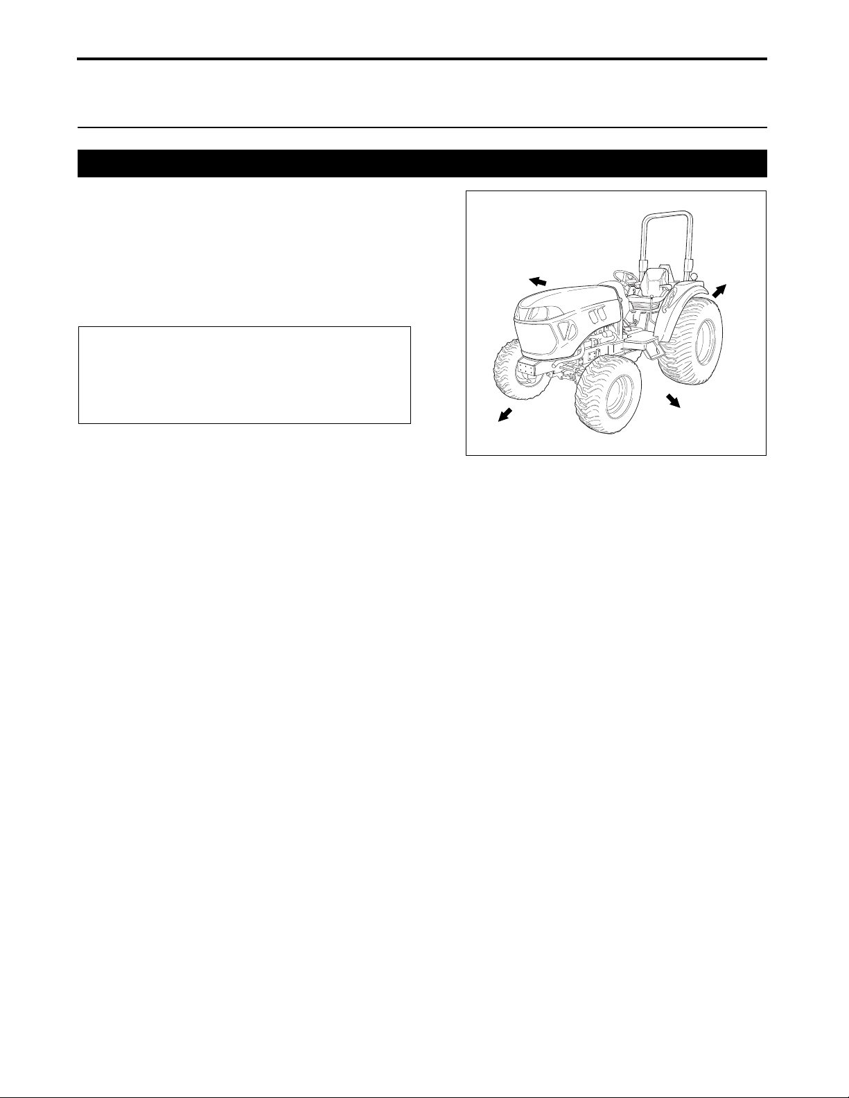
450_000_Lxa
LEFT
REARRIGHT
FRONT
1. SAFETY PRECAUTIONS
1. About The Operator’s Manual
The Operator’s Manual presents messages that help the
operator remain aware of potential hazards and possible
tractor damage in operating and servicing the tractor.
Carefully study all of the information in the Operator’s
Manual so that the operator can avoid personal injury or
property damage.
NOTE
● Unless otherwise stated, the expressions right
hand side, left hand side, front side and rear side,
used throughout the Operator’s Manual are
relative to the operator’s position.
1-1
Lx410/450/490 Operator's Manual
Page 12

2. Safety Alert Symbol
! DANGER
! WARNING
! CAUTION
NOTICE
The safety alert symbol appears with
most safety statements. The safety
alert symbol means attention, become
alert, the operator’s safety is involved!
Please read and strictly observe the
message that follows the safety alert
symbol.
1. SAFETY PRECAUTIONS
Indicates a hazardous situation which, if not
avoided, could result in minor or moderate injury.
Indicates a situation which can cause damage to the
tractor, personal property and/o r th e en vir onment or
cause the equipment to operate imprope rly.
Indicates a hazardous situation which, if not
avoided, will result in death or serious injury.
Indicates a hazardous situation which, if not
avoided, could result in death or serious injury.
WARNING: READ AND FOLLOW ALL INSTRUCTIONS IN THE OPERATOR’S MANUAL
BEFORE ATTEMPTING TO OPERATE THE TRACTOR. FAILURE TO COMPLY WITH THE
INSTRUCTIONS MAY RESULT IN PERSONAL INJURY.
WARNING: The engine exhaust, some of its constituents and certain tractor compo nen ts con tai n
or emit chemicals known to the State of California to cause cancer, birth defects or other
reproductive harm.
DANGER: The tractor is built to be operated according to the rules for safe operation in the
Operator’s Manual. As with any type of power equipment, carelessness or error on the part of the
operator can result in serious injury. To help prevent accidents, read and take the following
precautions before operating the tractor. Failure to observe the following safety instructions could
result in serious injury or death.
IMPORTANT: Means that implement or
property damage could occur if instructions are
ignored.
NOTE: Provides useful information.
Lx410/450/490 Operator's Manual
1-2
Page 13
1. SAFETY PRECAUTIONS
3. Precautions Before Operating The Tractor
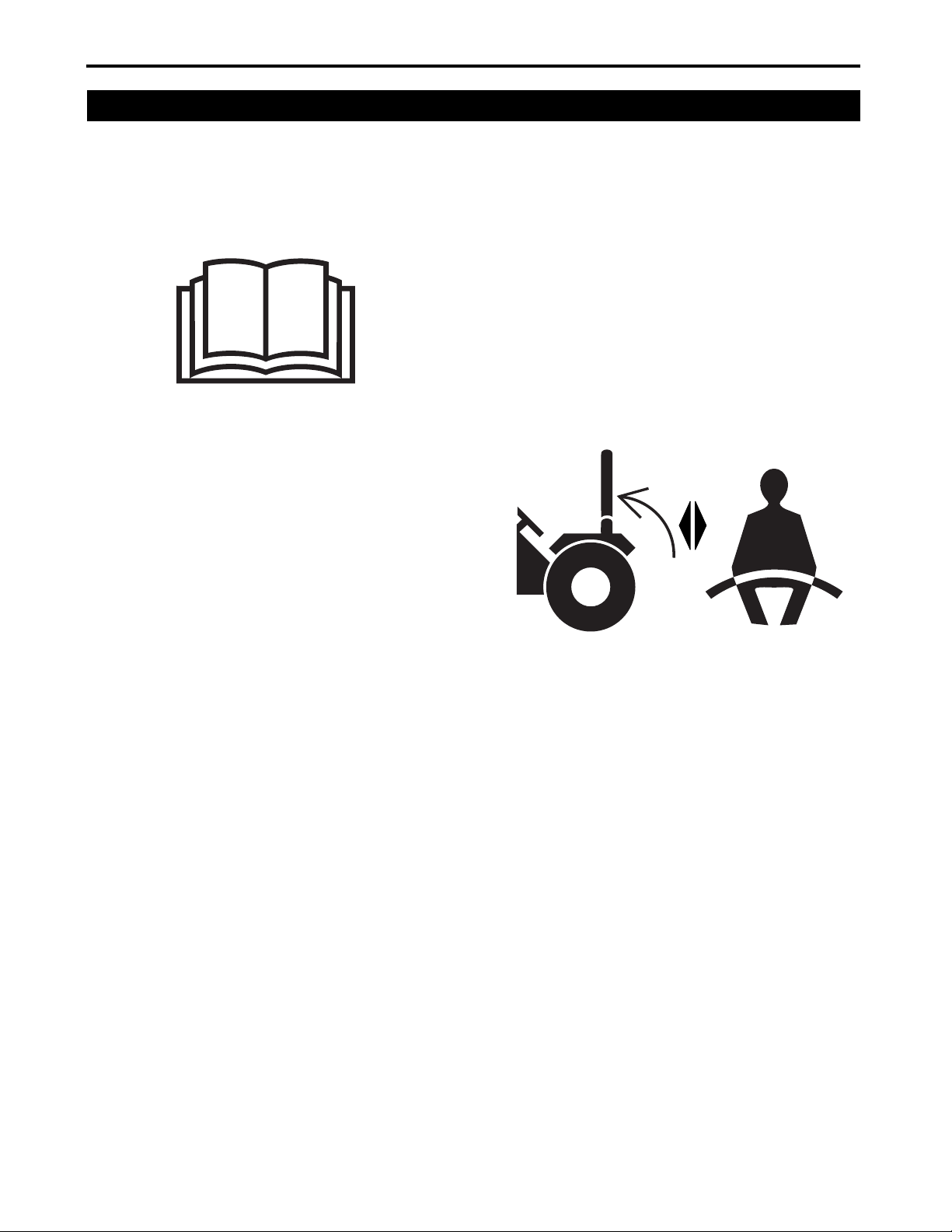
1. Understand the performance and limitations of
the tractor. Carefully study the Operator’s Manual
and learn the instructions in the Operator's
Manual before operating or servicing the tractor.
Keep the Operator’s Manual in an easily
accessible place.
2. Strictly follow the statements given in the
DANGER, WARNING and CAUTION safety
decals attached to the tractor.
3. Do not operate the tractor with the Roll-Over
Protective Structure (ROPS) in the folded "down"
position.
Keep the retractable seatbelt fastened while
operating the tractor with the Roll-Over Protective
Structure (ROPS) in the unfolded "up" position.
The preceding practice will reduce the possibility
of injury or death in the event of roll over
accident.
If the Roll-Over Protective Structure (ROPS) has
been removed for any reason, ensure to install all
the associated parts before operating the tractor.
Do not alter the Roll-Over Protective Structure
(ROPS). The altered Roll-Over Protective
Structure (ROPS) may fail to provide the
designed protection.
Replace the damaged Roll-Over Protective
Structure (ROPS) immediately. Contact YOUR
LOCAL YANMAR TRACTOR DEALER for
technical assistance.
The foldable Roll-Over Protective Structure
(ROPS) may be temporarily folded down when
absolutely necessary for areas with height
limitations. Remember that when the Roll-Over
Protective Structure (ROPS) is in the "down"
position, the Roll-Over Protective Structure
(ROPS) does not provide operator protection and
the retractable seatbelt should not be worn.
For operator safety, always keep the Roll-Over
Protective Structure (ROPS) in the unfolded "up"
position and locked securely.
NEVER alter or repair the Roll-Over Protective
Structure (ROPS). Welding, bending, drilling,
grinding, or cutting may weaken the Roll-Over
Protective Structure (ROPS). Contact YOUR
LOCAL YANMAR TRACTOR DEALER for
technical assistance.
4. Always fasten the retractable seatbelt while
operating the tractor with the Roll-Over Protective
Structure (ROPS) in the unfolded "up" position.
Check the retractable seatbelt for any damage.
Replace the damaged retractable seatbelt
immediately. Contact YOUR LOCAL YANMAR
TRACTOR DEALER for technical assistance.
Do not use the retractable seatbelt if the RollOver Protective Structure (ROPS) is in the folded
"down" position or the tractor does not have the
Roll-Over Protective Structure (ROPS).
5. Check overhead clearance carefully before
driving under power lines, wires, bridges or low
hanging tree branches, before entering or leaving
buildings, or in any other situation where the
operator and/or Roll-Over Protective Structure
(ROPS) may be struck, which could result in
serious injury.
6. Make sure that the usual operator and any other
person who will operate the tractor studies the
Operator’s Manual before operation. Know the
controls and how to stop the tractor quickly.
7. Make sure that any person or obstacle is not
under or around the tractor before and during
operation. Make sure to maintain sufficient
overhead clearance above the tractor.
8. Do not operate the tractor and/or implement
installed on the tractor while under the influence
of alcohol, drugs, medicine or controlled
substance/s or when not fit to operate the tractor.
9. During operation and when performing service
work:
• Wear close-fitting clothing.
• Do not wear loose-fitting clothes, jewelry, baggy
or torn clothing.
1-3
Lx410/450/490 Operator's Manual
Page 14

1. SAFETY PRECAUTIONS
• When any of the preceding items is caught by a
moving part of the tractor, an accident can
happen.
• Do not wear cut-off pants or shorts which do not
provide protection against flying debris.
• Do not under any circumstances operate the
tractor with bare feet.
• Do not wear sandals or sneakers.
• Wear additional protection including non-slip
safety boots or shoes, protective goggles and
gloves, etc., as appropriate or required by
applicable local laws and regulations.
• Wear ear protection in a noisy environment to
prevent hearing damage and to reduce operator
fatigue.
10.Avoid allowing passenger/s on any portion of the
tractor.
11.Always remain seated in the operator seat while
operating the tractor.
12.Make sure that the brakes and other mechanical
components are properly adjusted and do not
have excessive wear.
• Immediately replace all excessively worn out or
damaged components.
• At regular intervals, check that all nuts, bolts and
screws are properly tightened.
(For details, see "Chapter 13. MAINTENANCE"
on page 13-1).
13.Always keep the tractor clean. Dust, grease or
grass clippings accumulated on the tractor can
lead to fire accidents or personal injury.
14.Use the handholds and running board step when
getting on and off the tractor to help prevent
accidental falls. Keep the running board step
clear of mud and debris.
15.Only use the implements that satisfy the
requirements in the Operator's Manual or are
approved by your Yanmar tractor dealer. (For
details, see "Chapter 4. IMPLEMENT
CAPACITIES" on page 4-1).
16.When using front, mid- or rear mounted
implements, install an appropriate weight/s to the
front or rear of the tractor to prevent up setting the
tractor. When using the mid-implement, the
operator may use front and rear weights. If the
operator choose to use the loader, mount an
implement or weight to the 3-point hitch in order
to stabilize the tractor. Observe the instructions
about safety in the Operator’s Manual for the
implement to be used.
17.Remember that a narrower tire tread width can
lead to greater possibility of upsetting the balance
of the tractor. To positively stabilize the tractor,
select a maximum possible tire tread width
appropriate for the intended application. (For
details, see "Change the Tire Tread Width" on
page 12-3).
18.Do not under any circumstances modify the
tractor. Modification can deteriorate the
performance and/or safety of the tractor, possibly
leading to personal injury or property damage.
19.Do not attempt to adjust the low or high idle
speed limit screw. Adjusting the low or high idle
speed limit screw may impair the safety and
performance of the tractor and shorten the life of
the tractor.
4. Safe Practices for Operating the Tractor
1. Start the Tractor
1. Remain seated in the operator seat when starting
the engine or actuating the levers or controls. Do
not start the engine or operate controls while
standing beside the tractor.
2. Before starting the engine, ensure that all the
levers are in the N (neutral) positions, the parking
brake is engaged securely, and Power Take Off
(PTO) switch is in the OFF position.
3. Always keep the retractable seatbelt fastened
around the operator’s waist whenever the Roll-
Lx410/450/490 Operator's Manual
4. If the tractor is started where there is a height
5. Start the engine of the tractor only by using the
1-4
Over Protective Structure (ROPS) is in the
unfolded "up" position and locked securely.
limitation, immediately return the Roll-Over
Protective Structure (ROPS) to the unfolded "up"
position and locked securely and fasten the
retractable seatbelt.
starter key switch. Avoid starting the engine by
short circuiting across the starter solenoid
terminals with a jumper wire, or by bypassing the
safety start switch. This defeats the safety
Page 15

1. SAFETY PRECAUTIONS
interlock circuit and the tractor may begin to
move and/or the Power Take Off (PTO) shafts
may begin to rotate, possibly leading to personal
injury or property damage.
6. Avoid running or idling the engine in a confined
area that is poorly ventilated or not ventilated at
all. The engine emits carbon monoxide gas that is
colorless, odorless and can cause death.
7. Before operation, check that all the safety
features are functioning correctly. Never tam per
with safety devices. Check the proper operation
regularly. Contact YOUR LOCAL YANMAR
TRACTOR DEALER for safety devices
malfunction.
8. Avoid accidental contact with control pedals while
the engine is running, as this can cause
unexpected movement of the tractor.
9. Always attend to the running tractor.
2. Work with the Tractor
1. Tow an implement only with the drawbar. Avoid
hitching via the axle housing. The tractor ca n
upset its balance, leading to serious injury or
death. Make sure the drawbar pin is locked in
place.
2. Any towed vehicle with the total weight exceeding
that of the tractor should be equipped with its own
braking system that is operational from the tractor
operator seat.
3. Make sure that all the covers and guards are in
position. Replace any missing or damaged
covers immediately.
4. Before turning or during traveling on a rough
terrain, or before stopping, decrease the tractor
speed in order to prevent upsetting.
5. Use extra caution during operating over rough
ground, when crossing ditches or operating on
slopes and when turning corners.
6. Avoid turning with the differential lock engaged.
Attempting to turn the tractor while the differential
lock is engaged can lead to a roll over.
7. Stay clear of ditches, potholes, embankments or
ponds. The incident of upsetting the tractor can
occur more on soft or wet ground. Before
entering an area covered with tall grass, inspect
the area to detect any obstacles.
8. The operator should always pay attention for
blind corners, trees and other object that can
obstruct the operator's vision. The operator
should always remain alert when approaching the
row of trees or any obstacle.
9. When two or more people are working in one
area, always keep in good communication
between each other.
10.Do not under any circumstances get on or off the
moving tractor.
11.When driving at night, ensure that all necessary
lights are illuminated.
12.When driving, do not shift the range gear. Always
shift the range gear when the tractor is
completely stopped.
3. Stop the Tractor
The procedures of stopping the tractor are as
follows:
1. Make sure that the left side brake pedal and the
right side brake pedal are connected with the
brake pedal connector lock.
2. Reduce the engine speed.
3. Depress the clutch pedal completely to
disengage the clutch.
4. Depress the brake pedals to stop the tractor.
5. Move the primary gear to the N (neutral) position.
4. Considerations for Safety of a Child
Tragic accidents can occur if the operator is not alert
to the presence of a child. A child is often attracte d to
the tractor. A child does not understand the dangers.
Never assume a child will remain where the operator
last saw the child.
1. Keep a child out of the operating area and under
the watchful care of an adult other than the
operator.
1-5
Lx410/450/490 Operator's Manual
Page 16
1. SAFETY PRECAUTIONS
A2019005
! WARNING
2. Be alert if a child enters the work area, stop the
tractor immediately.
3. Never allow a child to ride on the tractor. The
child can fall off and be seriously injured or
interfere with safe tractor operation.
4. Never allow a child under 16 years old to operate
the tractor. A child, 16 years old and under should
only operate the tractor under close parental
supervision and proper instruction.
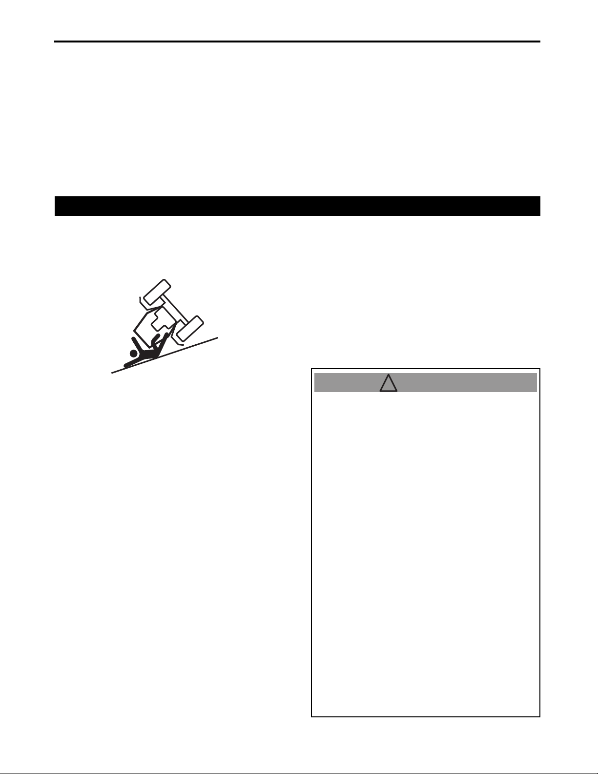
5. Operate the Tractor on Slopes
On a slope, the tractor is less stable and more pr one
to tip over, possibly leading to serious injury or dea th.
Remain very cautious while the tractor is on any
slope.
5. Be extremely careful when backing the tractor.
Before and during backing, look back and
downward. A child may be in the path.
6. Use extra care when approaching blind corners,
shrubs, trees or other objects that may obscure
the operator’s vision of a child or other hazard.
7. Never allow a child to play on the tractor or
implement.
8. Keep a child away from hot or running engine.
The child may suffer burns.
to avoid false confidence in the tractor’s ability to
climb slopes.
● To improve stability on a slope, select the widest
possible tire tread width. Observe the instructions
for appropriate weighting.
DO NOT:
● Keep away from drop-offs, ditches or
embankments during mowing. The mower could
suddenly turn over if a wheel goes over the edge
of a cliff, ditch or if an edge caves in.
DO:
● Operate up and down slopes, not across.
● Remove obstacles such as rocks, limbs, etc.
● Watch for potholes, ruts or bumps. Uneven terra in
can overturn the tractor. Tall grass can hide such
obstacles.
● Place the transmission in the low range when
climbing or descending slopes. Always keep the
tractor in gear when going down slopes to take
advantage of engine braking action.
● Keep all movement on the slopes slow and
gradual. Do not make sudden changes in spee d or
direction. Rapid engagement or braking can ca use
the front of the tractor to lift and rapidly tip over
backwards which can cause serious injury.
● Avoid starting or stopping on a slope. If tires lose
traction, push down Power Take Off (PTO) switch
to OFF position and proceed slowly straight down
the slope.
● To avoid upset, move backward up a steep slope.
If backing on the slope is difficult, do not attempt to
continue. Avoid an extremely steep slope.
● When moving forward to get out from a d itch, deep
mud or when traveling on a steep slope, the risk of
the tractor upsetting backward is high. Always
move backward to get out from these situations. In
the 4-wheel drive mode, special caution is needed
Lx410/450/490 Operator's Manual
● Before approaching a slope, select an
appropriate speed setting. Make sure to run
the tractor at a lower speed on slopes. Never
attempt to shift gears on a slope. The tractor
can suddenly go downhill out of control.
Avoid increasing and decreasing the tractor
speed rapidly.
● Do not move the range gear lever in the N
(neutral) position when on a slope.
● When climbing or descending a slope, do not
shift the range gear lever. Shifting the range
gear lever into the N (neutral) position can
result in loss of control of the tractor.
● Starting the tractor with the front end uphill
can cause the front wheels to jump off the
ground and this situation poses an extreme
danger. To avoid this problem, run the engine
at a lower speed, and gently start the tractor.
● Avoid parking the tractor on a slope. If
parking on a slope is unavoidable, chock all
the tires safely and securely and engage the
parking brake securely, for details, see "6.
Lock and Set the Parking Brake" on page 7-4.
● Avoid depressing the clutch pedal when
operating on a slope.
1-6
Page 17

6. Travel on a Road
1. SAFETY PRECAUTIONS
1. Disengagement of the 4-wheel drive is
recommended.
2. Remember that the braking characteristics differ
between the 2-wheel drive and 4-wheel drive
modes. Be aware of the current drive mode and
use carefully.
3. Release the clutch pedal slowly.
4. Before turning, always slow down the tractor.
High speed turn may cause the tractor to tip over.
5. When traveling on a road, ensure that the Slow
Moving Vehicle (SMV) emblem is on the rear of
tractor and is clearly visible. Use the hazard lights
and turn signal lights as required by the currently
effective local laws or regulations.
6. Strictly observe all the currently effective local
traffic and safety laws and regulations.
7. Turn ON the headlights as required by the
currently effective local laws or regulations.
8. Always travel at a speed that allows the operator
to maintain control of the tractor.
7. Safe Practices for Parking the Tractor
9. Avoid engaging differential lock while traveling o n
a road. It may cause the operator to lose control
of the tractor.
10.While traveling on a road, do not tur n the steering
wheel suddenly. Such an action can lead to loss
in the stability of the tractor and can cause an
extremely dangerous situation.
11.While on a road, do not attempt to operate an
implement. During transportation, place the 3point hitch control lever in the raised position and
lock the 3-point hitch control lever with the
position stop knob. Do not fully close the
hydraulic flow control/stop knob to hold an
implement in the raised position while the tractor
is traveling with the implements.
The preceding action can cause damage to the
hydraulic lift circuit.
12.When towing implement, connect a safety chain
to the implement and mount a Slow Moving
Vehicle (SMV) emblem on the rear of the tractor.
1. Push down Power Take Off (PTO) switch to OFF
position, lower the implements to the ground,
move all the levers to N (neutral) position,
engage the parking brake securely, for details,
see "6. Lock and Set the Parking Brake" on page
7-4, shut off the engine and remove the key.
2. Before leaving the tractor, ensure that the tractor
is completely stopped.
3. Avoid parking the tractor on a steep slope.
Rather, park on solid and level ground whenever
possible. If parking on a slope is unavoidable,
park the tractor across the slope and lower the
implement to the ground and chock all the tires
safely and securely.
1-7
Lx410/450/490 Operator's Manual
Page 18

1. SAFETY PRECAUTIONS
8. Operate the Power Take Off (PTO)
1. Before connecting/disconnecting, adjusting,
cleaning or servicing Power Take Off (PTO)
driven implement, ensure that all the moving
components are not moving.
2. Make sure that Power Take Off (PTO) shaft cap
is always in place. Replace Power Take Off
(PTO) shaft cap only when the shaft is not
moving.
3. Before installing or operating the Power Take Off
(PTO) driven implement, carefully study the
Operator's Manual of the implement and the
safety decals on the implement.
4. When installing stationary Power Take Off (PTO)
driven implements, ensure to engage the parking
brake securely, for details, see "6. Lock and Set
the Parking Brake" on page 7-4, chock all the
tires safely and securely. Avoid approaching or
accessing any rotating component.
5. Make sure to remove the drawbar before using
the Power Take Off (PTO).
9. Use the 3-Point Hitch
1. Use the 3-point hitch only in conjunction with the
implement that is specifically designed for use
with the 3-point hitch.
2. Before using the 3-point hitch mounted
implement, the appropriate weight may need to
be installed on the front of the tractor.
3. While on a road, do not attempt to operate an
implement. During transportation, place the 3point hitch control lever in the raised position and
lock the 3-point hitch control lever with the
position stop knob.
Do not fully close the hydraulic flow control/stop
knob to hold an implement in the raised position
while the tractor is traveling with the implement.
The preceding action can cause damage to the
hydraulic lift circuit.
10. Roll-Over Protective Structure (ROPS) Precautions
The tractor is equipped with a Roll-Over Protective
Structure (ROPS) which must be maintained in a fully
functional condition. Check overhead clearance
carefully before driving under power lines, wires,
bridges or low hanging branches, before entering or
leaving buildings, or in any other situation where the
operator and/or Roll-Over Protective Structure
(ROPS) can be struck, which can result in serious
injury.
3. Use only genuine parts to replace any damaged
part/s of the Roll-Over Protective Structure
(ROPS).
4. Never attach ropes, chains or cables to the RollOver Protective Structure (ROPS) for pulling
purposes.
5. Although the Roll-Over Protective Structure
(ROPS) provides the maximum protection
possible, always take necessary precautions.
1. Always keep the Roll-Over Protective Structure
(ROPS) on its original condition.
2. Replace the Roll-Over Protective Structure
(ROPS) whenever the Roll-Over Protective
Structure (ROPS) has been damaged. The
preceding action can weaken the structure and
endanger the safety of the operator.
Lx410/450/490 Operator's Manual
1-8
Page 19
1. SAFETY PRECAUTIONS
11. Safe Practices for Servicing the Tractor
Before starting any service work, park the tractor on
solid and level ground, engage the parking brake
securely, for details, see "6. Lock and Set the Parking
Brake" on page 7-4, lower the implement to the
ground, move all the levers to N (neutral) position,
push down Power Take Off (PTO) switch to OFF
position, shut off the engine and remove the key.
1. Always keep a first aid kit and a fire extinguisher
readily available.
2. Before accessing the engine, muffler, ra dia to r
and radiator cap or other possibly hot
components, wait until the tractor has fully cooled
down.
9. Prior to “jump starting” a tractor that has fully
depleted battery, read and follow all the
instructions in “Chapter 15. SERVICE THE
ELECTRICAL SYSTEM” on page 15-1.
10.Add coolant or water to the reserve tank, not to
the radiator (For details, see “Check the Cooling
System” on page 14-14).
11.Before working on or around electrical
components, disconnect the negative (–) battery
terminal first.
12.To prevent a spark occurring from short circ uit,
disconnect the negative (–) battery terminal first
and reconnect last.
3. Use extreme care in handling diesel fuels. Diesel
fuels are extremely flammable and the vapors are
explosive. Use only a container approved by the
local effective law.
4. Make sure to shut off the engine before refueling.
After refueling, replace fuel filler cap securely and
wipe off any spilled diesel fuel before starting the
engine as the diesel fuel may cause a fire or
explosion.
5. Do not smoke while refueling. Keep any spark or
open flame away from the fuel tank.
6. Never refuel the tractor indoors because diesel
fuel vapors will accumulate in the area.
7. Never store the fuel container or tractor indoor
where there is an open flame or spark, such as a
gas water heater, space heater or furnace.
8. Do not smoke while working around the battery.
Keep any sparks or open flame away from the
battery. The battery emits hydrogen and oxygen
gasses, in particular during recharging and can
pose a hazard of explosion.
13.The operator must not mount a tire onto a rim.
Only qualified person must mount tire onto a rim.
14.Always keep the tires at the correct tire air
pressure level. Avoid exceeding the
recommended tire air pressure specified in the
Operator’s Manual.
15.Keep the tractor securely supported while
changing the wheels or adjusting the tire tread
width. Make sure to tighten the wheel bolts to the
specified tightening torque.
1-9
Lx410/450/490 Operator's Manual
Page 20

1. SAFETY PRECAUTIONS
16.Avoid working under any hydraulically supported
devices. Such devices can leak, suddenly settle
down, or be accidentally lowered. If working
beneath the tractor or an implement is
unavoidable, ensure to use a stand or lift
apparatus with the capacity of more than 3 tons.
17.High pressure hydraulic fluid when released can
penetrate human skin, possibly leading to serious
personal injury. Before disconnecting any
hydraulic line, fully release the internal pressure.
Before exerting a pressure to the hydraulic
system, ensure that all connections are tight and
all the lines, pipes and hoses are free from
fractures/fissures or any other damage.
18.Check brake operation frequently. Adjust and
service as required.
19.Avoid changing the engine governor settings or
overspeed the engine. Excessive engine speeds
are dangerous.
20.Observe proper waste disposal laws and
regulations. Prior to disposal, determine the
proper method to dispose of waste from your
local Environmental Protection Agency.
Recycling centers are established to properly
dispose of materials in an environmentally safe
fashion.
21.Use container approved by the effective law
when draining fluids. Avoid using food or
beverage containers that can mislead someone
into drinking from food or beverage containers.
Properly dispose of the containers immediately
following the draining of fluids.
22.Observe your local Environmental Protection
Agency regulations when disposing of oil, fuel,
coolant, brake fluids, filters, batteries, tires and
other harmful waste.
23.Yanmar does not recommend the use of a
pressure washer or garden hose to clean the
tractor. Electrical components, spindles, pulleys,
bearings or the engine can be damaged. Th e use
of water will result in shortened life and reduce
serviceability.
WARNING: THE OWNER/OPERATOR RESPONSIBILITY: Restrict the use of the tractor to
persons who read, understand and follow the warnings and instructions in the Operator’s
Manual and on the tractor.
Lx410/450/490 Operator's Manual
1-10
Page 21

1. SAFETY PRECAUTIONS
12. Replace the Rubber Product/s, such as Hydraulic Hose, Fuel Hoses,
Power Steering Hoses, Radiator Hoses and Air Int ake Hose for Every 2
Years
The rubber product/s has/have a deteriorative character.
The deteriorated rubber product/s may cause defects and
damages such as fluid leakage, loss control of the tractor
during operation, fire, burn injury.
13. Understand the Tractor Safety Decals
■ Safety Alert Symbol
The tractor safety decals illustrated in this section are
provided in critical areas on the tractor so that people
including the operator can remain always aware of
potential hazards.
The tractor safety decals contain the words DANGER,
WARNING and CAUTION together with the safety alert
symbol. DANGER and WARNING stand for the most
serious hazards.
The Operator’s Manual also contains special safety
messages that explain potential hazards about which the
operator must remain cautious. The messages are
presented together with the word CAUTION and the
safety alert symbol.
■ Care of DANGER, WARNING and CAUTION Decals
1. Always keep all the DANGER, WARNING and
CAUTION decals clean and clearly legible.
2. Clean the DANGER, WARNING and CAUTION decals
with soap and water, wipe dry with clean soft cloth.
3. Replace damaged or missing DANGER, WARNING
and CAUTION decals with new decals available from
YOUR LOCAL YANMAR TRACTOR DEALER.
4. If a component having a DANGER, WARNING and
CAUTION decals is replaced with a new decal, ensure
that the new decal is on the same location as of the old
component.
5. Affix a new DANGER, WARNING and CAUTION
decals flat on a clean and dry surface, squeezing out
trapped air.
1-11
Lx410/450/490 Operator's Manual
Page 22
1. SAFETY PRECAUTIONS
450_001_ROPS
(A)
! WARNING
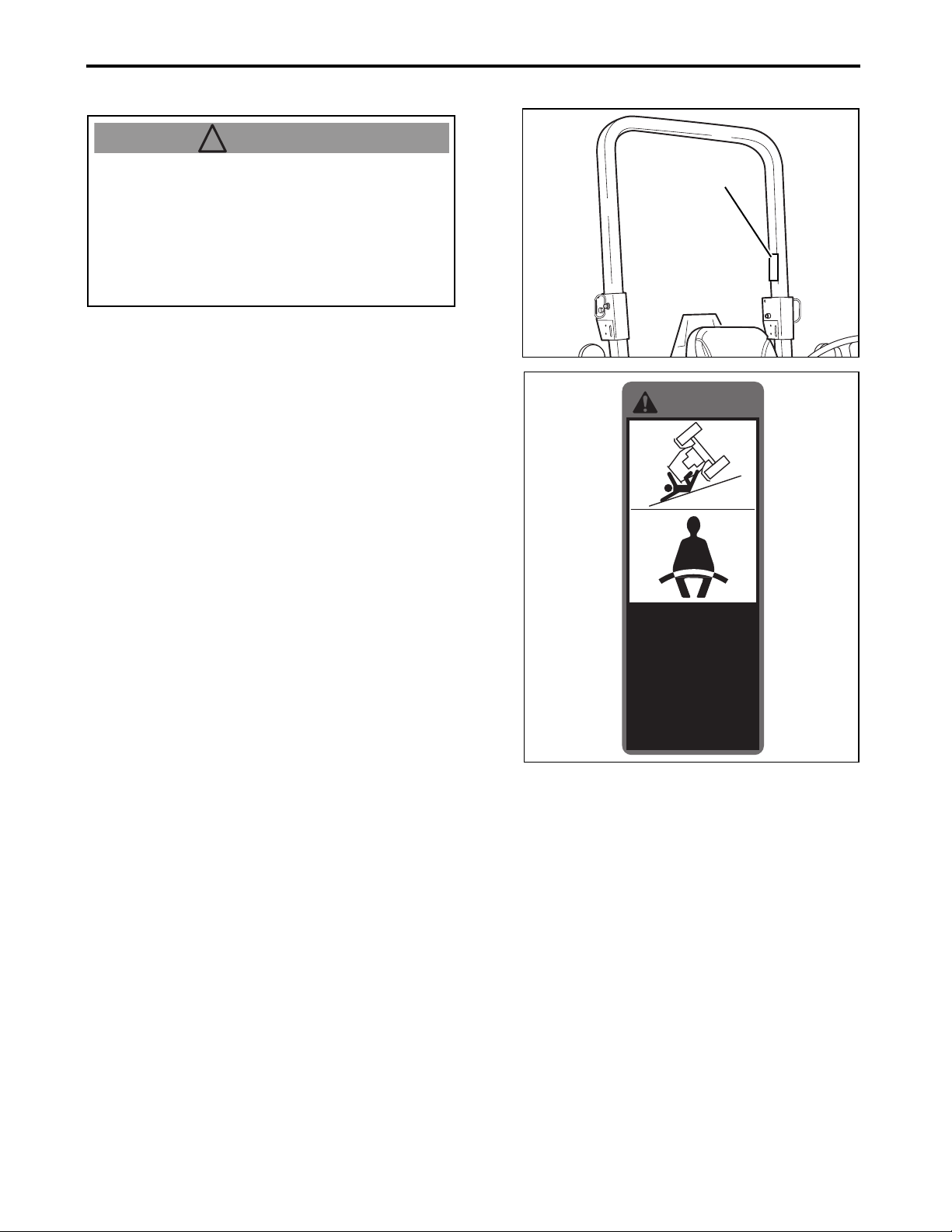
(A) 1A8250-65800
ROLL-OVER HAZARD!
● NEVER operate without seatbelt fastened.
● NEVER jump if machine tips.
● NEVER remove, repair or modify ROPS.
● ALWAYS replace a damaged ROPS.
● Failure to comply could result in death or
serious injury.
㪮㪘㪩㪥㪠㪥㪞
㪩㪦㪣㪣㪄㪦㪭㪜㪩㩷㪟㪘㪱㪘㪩㪛㩸
䍃㪥㪜㪭㪜㪩㩷㫆㫇㪼㫉㪸㫋㪼㩷㫎㫀㫋㪿㫆㫌㫋
㩷㫊㪼㪸㫋㪹㪼㫃㫋㩷㪽㪸㫊㫋㪼㫅㪼㪻㪅
䍃㪥㪜㪭㪜㪩㩷㫁㫌㫄㫇㩷㫀㪽㩷㫄㪸㪺㪿㫀㫅㪼㩷㫋㫀㫇㫊㪅
䍃㪥㪜㪭㪜㪩㩷㫉㪼㫄㫆㫍㪼㪃㩷㫉㪼㫇㪸㫀㫉㩷㫆㫉
㩷㫄㫆㪻㫀㪽㫐㩷㪩㪦㪧㪪㪅
䍃㪘㪣㪮㪘㪰㪪㩷㫉㪼㫇㫃㪸㪺㪼㩷㪸㩷㪻㪸㫄㪸㪾㪼㪻
㩷㪩㪦㪧㪪㪅
䍃㪝㪸㫀㫃㫌㫉㪼㩷㫋㫆㩷㪺㫆㫄㫇㫃㫐㩷㪺㫆㫌㫃㪻
㩷㫉㪼㫊㫌㫃㫋㩷㫀㫅㩷㪻㪼㪸㫋㪿㩷㫆㫉㩷㫊㪼㫉㫀㫆㫌㫊
㩷㫀㫅㫁㫌㫉㫐㪅
㪈㪘㪏㪉㪌㪇㪄㪍㪌㪏㪇㪇
Lx410/450/490 Operator's Manual
1-12
Page 23
1. SAFETY PRECAUTIONS
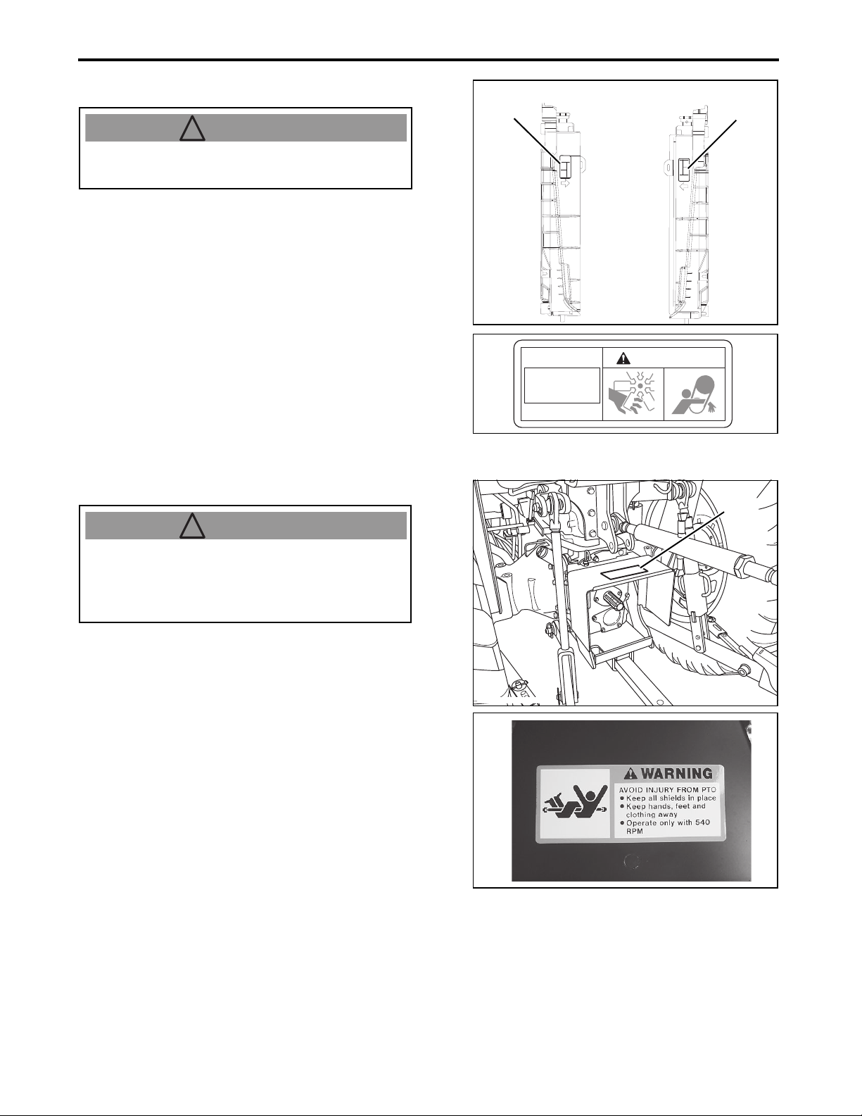
450_002_Fender
(B)
! WARNING
450_002_Fender
(C)
! DANGER
㪈㪘㪏㪉㪌㪇㪄㪍㪌㪊㪇㪇
㪛㪘㪥㪞㪜㪩
㪫㪦㩷㪘㪭㪦㪠㪛㩷㪠㪥㪡㪬㪩㪰㩷㪦㪩㩷㪛㪜㪘㪫㪟㪑
䊶㪛㫆㩷㫅㫆㫋㩷㫊㫋㪸㫉㫋㩷㪼㫅㪾㫀㫅㪼㩷㪹㫐
䇭㫊㪿㫆㫉㫋㫀㫅㪾㩷㪸㪺㫉㫆㫊㫊㩷㫊㫋㪸㫉㫋㪼㫉
䇭㫋㪼㫉㫄㫀㫅㪸㫃㫊㩷㫆㫉㩷㪹㫐㫇㪸㫊㫊㫀㫅㪾
䇭㫊㪸㪽㪼㫋㫐㩷㫊㫋㪸㫉㫋㩷㫊㫎㫀㫋㪺㪿㪅
䊶㪪㫋㪸㫉㫋㩷㪼㫅㪾㫀㫅㪼㩷㫆㫅㫃㫐㩷㪽㫉㫆㫄
䇭㫊㪼㪸㫋㩷㩷㫎㫀㫋㪿㩷㫋㫉㪸㫅㫊㫄㫀㫊㫊㫀㫆㫅
㩷㪸㫅㪻㩷㪧㪫㪦㩷㪦㪝㪝㪅
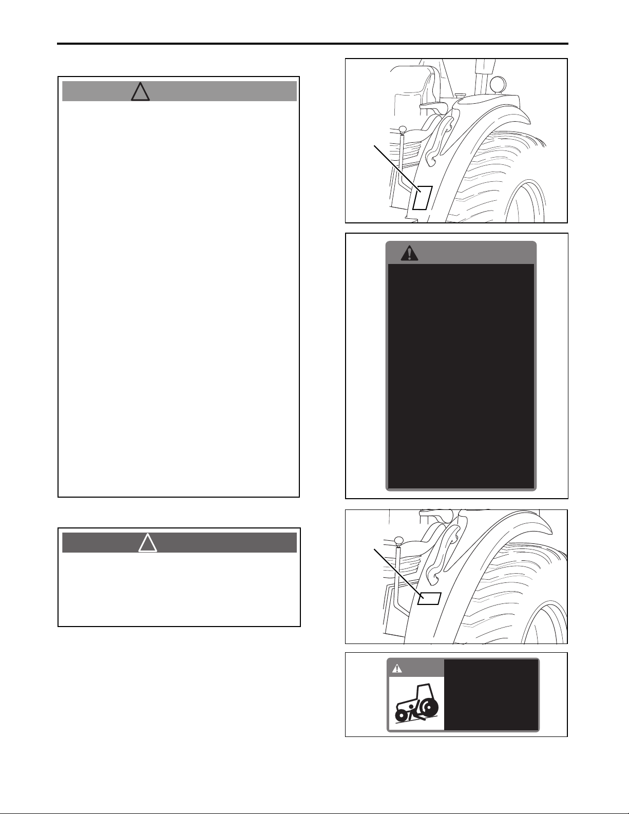
(B) 1A8240-65320
1. Read this Operator's Manual before
operating this tractor.
2. Do not operat e the machine without properly
working guards, shields, and other safety
devices in place and working.
3. Hitch towed loads only to drawbar to avoid
rearward upset.
4. Make certain everyone is clear of machine
before starting engine or operation.
5. Keep all riders off tractor and equipment.
6. Keep hands, feet and clothing away from
power-driven parts.
7. Fasten seat belt while operating tractor.
8. Reduce speed when turning or operating
around hazards, on rough ground or steep
slopes.
9. Couple br ake pe dals to gether fo r ro ad tra vel.
10.Do not allow operation of the machine by
untrained personnel.
11.Use flashing warning lights on highway
unless prohibited by law.
12.Stop engine, lower implement to ground and
lock park brake before dismounting.
13.Wait for all movement to stop before
servicing machinery.
14.Remove key if leaving tractor unattended.
15.Securely support tractor and implements
before working underneath.
㪮㪘㪩㪥㪠㪥㪞
䇭㪈㪅
㪩㪼㪸㪻㩷㪦㫇㪼㫉㪸㫋㫆㫉㩾㫊㩷㪤㪸㫅㫌㪸㫃㩷㪹㪼㪽㫆㫉㪼㩷㫆㫇㪼㫉㪸㫋㫀㫅㪾
㫋㪿㫀㫊㩷㫋㫉㪸㪺㫋㫆㫉㪅
䇭㪉㪅
㪛㫆㩷㫅㫆㫋㩷㫆㫇㪼㫉㪸㫋㪼㩷㫋㪿㪼㩷㫄㪸㪺㪿㫀㫅㪼㩷㫎㫀㫋㪿㫆㫌㫋
㪾㫌㪸㫉㪻㫊㪃㫊㪿㫀㪼㫃㪻㫊㪃㪸㫅㪻㩷㫊㪸㪽㪼㫋㫐㩷㪻㪼㫍㫀㪺㪼㫊㩷㫀㫅
㫇㫃㪸㪺㪼㩷㪸㫅㪻㩷㫎㫆㫉㫂㫀㫅㪾㪅
䇭㪊㪅
㪟㫀㫋㪺㪿㩷㫋㫆㫎㪼㪻㩷㫃㫆㪸㪻㫊㩷㫆㫅㫃㫐㩷㫋㫆㩷㪻㫉㪸㫎㪹㪸㫉㩷㫋㫆㩷㪸㫍㫆㫀㪻
㫉㪼㪸㫉㫎㪸㫉㪻㩷㫌㫇㫊㪼㫋㪅
䇭㪋㪅
㪤㪸㫂㪼㩷㪺㪼㫉㫋㪸㫀㫅㩷㪼㫍㪼㫉㫐㫆㫅㪼㩷㫀㫊㩷㪺㫃㪼㪸㫉㩷㫆㪽㩷㫄㪸㪺㪿㫀㫅㪼
㪹㪼㪽㫆㫉㪼㩷㫊㫋㪸㫉㫋㫀㫅㪾㩷㪼㫅㪾㫀㫅㪼㩷㫆㫉㩷㫆㫇㪼㫉㪸㫋㫀㫆㫅㪅
䇭㪌㪅
㪢㪼㪼㫇㩷㪸㫃㫃㩷㫉㫀㪻㪼㫉㫊㩷㫆㪽㪽㩷㫋㫉㪸㪺㫋㫆㫉㩷㪸㫅㪻㩷㪼㫈㫌㫀㫇㫄㪼㫅㫋㪅
䇭㪍㪅
㪢㪼㪼㫇㩷㪿㪸㫅㪻㫊㪃㩷㪽㪼㪼㫋㩷㪸㫅㪻㩷㪺㫃㫆㫋㪿㫀㫅㪾㩷㪸㫎㪸㫐㩷㪽㫉㫆㫄
㫇㫆㫎㪼㫉㪄㪻㫉㫀㫍㪼㫅㩷㫇㪸㫉㫋㫊㪅
㪝㪸㫊㫋㪼㫅㩷㫊㪼㪸㫋㩷㪹㪼㫃㫋㩷㫎㪿㫀㫃㪼㩷㫆㫇㪼㫉㪸㫋㫀㫅㪾䇭㪎㪅
㫋㫉㪸㪺㫋㫆㫉㪅
㩷㪏㪅
㪩㪼㪻㫌㪺㪼㩷㫊㫇㪼㪼㪻㩷㫎㪿㪼㫅㩷㫋㫌㫉㫅㫀㫅㪾㩷㫆㫉㩷㫆㫇㪼㫉㪸㫋㫀㫅㪾
㪸㫉㫆㫌㫅㪻㩷㪿㪸㫑㪸㫉㪻㫊㪃㩷㫆㫅㩷㫉㫆㫌㪾㪿㩷㪾㫉㫆㫌㫅㪻㩷㫆㫉
㫊㫋㪼㪼㫇㩷㫊㫃㫆㫇㪼㫊㪅
㪚㫆㫌㫇㫃㪼㩷㪹㫉㪸㫂㪼㩷㫇㪼㪻㪸㫃㫊㩷㫋㫆㪾㪼㫋㪿㪼㫉㩷㪽㫆㫉㩷㪐㪅
㫉㫆㪸㪻㩷㫋㫉㪸㫍㪼㫃㪅
㪈㪇㪅
㪛㫆㩷㫅㫆㫋㩷㪸㫃㫃㫆㫎㩷㫆㫇㪼㫉㪸㫋㫀㫆㫅㩷㫆㪽㩷㫋㪿㪼㩷㫄㪸㪺㪿㫀㫅㪼
㪹㫐㩷㫌㫅㫋㫉㪸㫀㫅㪼㪻㩷㫇㪼㫉㫊㫆㫅㫅㪼㫃㪅
㪈㪈㪅
㪬㫊㪼㩷㪽㫃㪸㫊㪿㫀㫅㪾㩷㫎㪸㫉㫅㫀㫅㪾㩷㫃㫀㪾㪿㫋㫊㩷㫆㫅㩷㪿㫀㪾㪿㫎㪸㫐
㫌㫅㫃㪼㫊㫊㩷㫇㫉㫆㪿㫀㪹㫀㫋㪼㪻㩷㪹㫐㩷㫃㪸㫎㪅
㪪㫋㫆㫇㩷㪼㫅㪾㫀㫅㪼㪃㫃㫆㫎㪼㫉㩷㫀㫄㫇㫃㪼㫄㪼㫅㫋㩷㫋㫆㩷㪾㫉㫆㫌㫅㪻
㪈㪉㪅
㪸㫅㪻㩷㫃㫆㪺㫂㩷㫇㪸㫉㫂㩷㪹㫉㪸㫂㪼㩷㪹㪼㪽㫆㫉㪼㩷㪻㫀㫊㫄㫆㫌㫅㫋㫀㫅㪾㪅
㪮㪸㫀㫋㩷㪽㫆㫉㩷㪸㫃㫃㩷㫄㫆㫍㪼㫄㪼㫅㫋㩷㫋㫆㩷㫊㫋㫆㫇㩷㪹㪼㪽㫆㫉㪼
㪈㪊㪅
㫊㪼㫉㫍㫀㪺㫀㫅㪾㩷㫄㪸㪺㪿㫀㫅㪼㫉㫐㪅
㪩㪼㫄㫆㫍㪼㩷㫂㪼㫐㩷㫀㪽㩷㫃㪼㪸㫍㫀㫅㪾㩷㫋㫉㪸㪺㫋㫆㫉㩷㫌㫅㪸㫋㫋㪼㫅㪻㪼㪻㪅㪈㪋㪅
㪪㪼㪺㫌㫉㪼㫃㫐㩷㫊㫌㫇㫇㫆㫉㫋㩷㫋㫉㪸㪺㫋㫆㫉㩷㪸㫅㪻㩷㫀㫄㫇㫃㪼㫄㪼㫅㫋㫊㪈㪌㪅
㪹㪼㪽㫆㫉㪼㩷㫎㫆㫉㫂㫀㫅㪾㩷㫌㫅㪻㪼㫉㫅㪼㪸㫋㪿㪅
㪈㪘㪏㪉㪋㪇㪄㪍㪌㪊㪉㪇
(C) 1A8250-65300
TO AVOID INJURY OR DEATH:
● Do not start engine by shorting across starter
terminals or bypassing safety start switch.
● Start engine only from seat with transmission
and PTO OFF.
1-13
Lx410/450/490 Operator's Manual
Page 24
(D) 1A8250-65310
450_005_L-Side
(D)
! WARNING
㪈㪘㪏㪉㪌㪇㪄㪍㪌㪊㪈㪇
㪮㪘㪩㪥㪠㪥㪞
㪫㪦䇭㪘㪭㪦㪠㪛䇭㪠㪥㪡㪬㪩㪰㪑
䊶㪪㫋㫆㫇㩷㪼㫅㪾㫀㫅㪼㪅
䊶㪪㪼㫋㩷㫇㪸㫉㫂㫀㫅㪾㩷㪹㫉㪸㫂㪼㪅
䊶㪧㪸㫉㫂㩷㫆㫅㩷㫃㪼㫍㪼㫃㩷㪾㫉㫆㫌㫅㪻㪅
䊶㪣㫆㫎㪼㫉㩷㪸㫃㫃㩷㫀㫄㫇㫃㪼㫄㪼㫅㫋㫊
䊶㪩㪼㫄㫆㫍㪼㪸㩷㫂㪼㫐㪅
㩷㫋㫆㩷㫋㪿㪼㩷㪾㫉㫆㫌㫅㪻㪅
㫊㪼㫉㫍㫀㪺㫀㫅㪾㩷㫄㪸㪺㪿㫀㫅㪼㪃
㪙㪼㪽㫆㫉㪼㩷㫃㪼㪸㫍㫀㫅㪾㩷㫆㫉
450_003_ROPS2
(E)
! WARNING
TO AVOID INJURY:
Before leaving or servicing machine,
● Stop engine.
● Set parking brake.
● Park on level ground.
● Lower all implements to the ground.
● Remove key.
1. SAFETY PRECAUTIONS
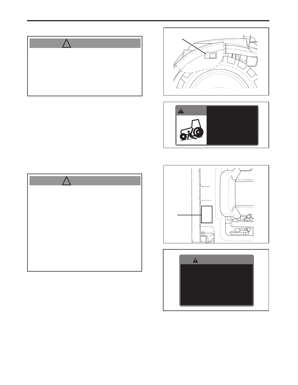
(E) 1A8250-65350
TO AVOID INJURY OR DEATH FROM
ROLLOVER:
● Keep Rollover Protective Structure (ROPS)
fully extended.
● Do not jump if machine tips.
● Use seat belt.
THERE IS NO OPERATOR PROTECTION WHEN
THE ROPS IS IN THE FOLDED POSITION.
● Fold the ROPS only when absolutely
necessary.
When the structure must be down:
• Do not use seat belt.
• Drive with extra care.
㪮㪘㪩㪥㪠㪥㪞
㪫㪦䇭㪘㪭㪦㪠㪛䇭㪠㪥㪡㪬㪩㪰㩷㪦㪩㩷㪛㪜㪘㪫㪟㩷㪝㪩㪦㪤㩷㪩㪦㪣㪣㪦㪭㪜㪩㪑
䊶㪢㪼㪼㫇㩷㪩㫆㫃㫃㫆㫍㪼㫉㩷㪧㫉㫆㫋㪼㪺㫋㫀㫍㪼㩷㪪㫋㫉㫌㪺㫋㫌㫉㪼㩷㩿㪩㪦㪧㪪㪀
㩷㪽㫌㫃㫃㫐㩷㪼㫏㫋㪼㫅㪻㪼㪻㪅
䊶㪛㫆㩷㫅㫆㫋㩷㫁㫌㫄㫇㩷㫀㪽㩷㫄㪸㪺㪿㫀㫅㪼㩷㫋㫀㫇㫊㪅
䊶㪬㫊㪼㩷㫊㪼㪸㫋㩷㪹㪼㫃㫋㪅
㪫㪟㪜㪩㪜㩷㪠㪪㩷㪥㪦㩷㪦㪧㪜㪩㪘㪫㪦㪩㩷㪧㪩㪦㪫㪜㪚㪫㪠㪦㪥䇭㪮㪟㪜㪥䇭㪫㪟㪜
㪩㪦㪧㪪㩷㪠㪪䇭㪠㪥㩷㪫㪟㪜㩷㪝㪦㪣㪛㪜㪛㩷㪧㪦㪪㪠㪫㪠㪦㪥㪅
䊶㪝㫆㫃㪻㩷㫋㪿㪼㩷㪩㪦㪧㪪㩷㫆㫅㫃㫐㩷㫎㪿㪼㫅㩷㪸㪹㫊㫆㫃㫌㫋㪼㫃㫐㩷㫅㪼㪺㪼㫊㫊㪸㫉㫐㪅
㪮㪿㪼㫅㩷㫋㪿㪼㩷㫊㫋㫉㫌㪺㫋㫌㫉㪼㩷㫄㫌㫊㫋㩷㪹㪼㩷㪻㫆㫎㫅㪑
䇭䊶㪛㫆㩷㫅㫆㫋㩷㫌㫊㪼㩷㫊㪼㪸㫋㩷㪹㪼㫃㫋㪅
䇭䊶㪛㫉㫀㫍㪼㩷㫎㫀㫋㪿㩷㪼㫏㫋㫉㪸㩷㪺㪸㫉㪼㪅
㪈㪘㪏㪉㪌㪇㪄㪍㪌㪊㪌㪇
Lx410/450/490 Operator's Manual
1-14
Page 25
1. SAFETY PRECAUTIONS
1a8250-6520 RIGHT
(F)
RIGHT LEFT
(F)
1a8250-6520 LEFT
! WARNING
(G)
450140205_P14-4_tofc_d2
! WARNING
(F) 1A7880-65610
● STAY CLEAR OF ENGINE FAN AND FAN
BELT.
(G) 198220-65621
AVOID INJURY FROM PTO:
● Keep all shields in place.
● Keep hands, feet and clothing away.
● Operate only with 540 RPM.
STAY CLEAR OF
ENGINE FAN
AND FAN BELT
WARNING
1A7880-65620
1-15
Lx410/450/490 Operator's Manual
Page 26
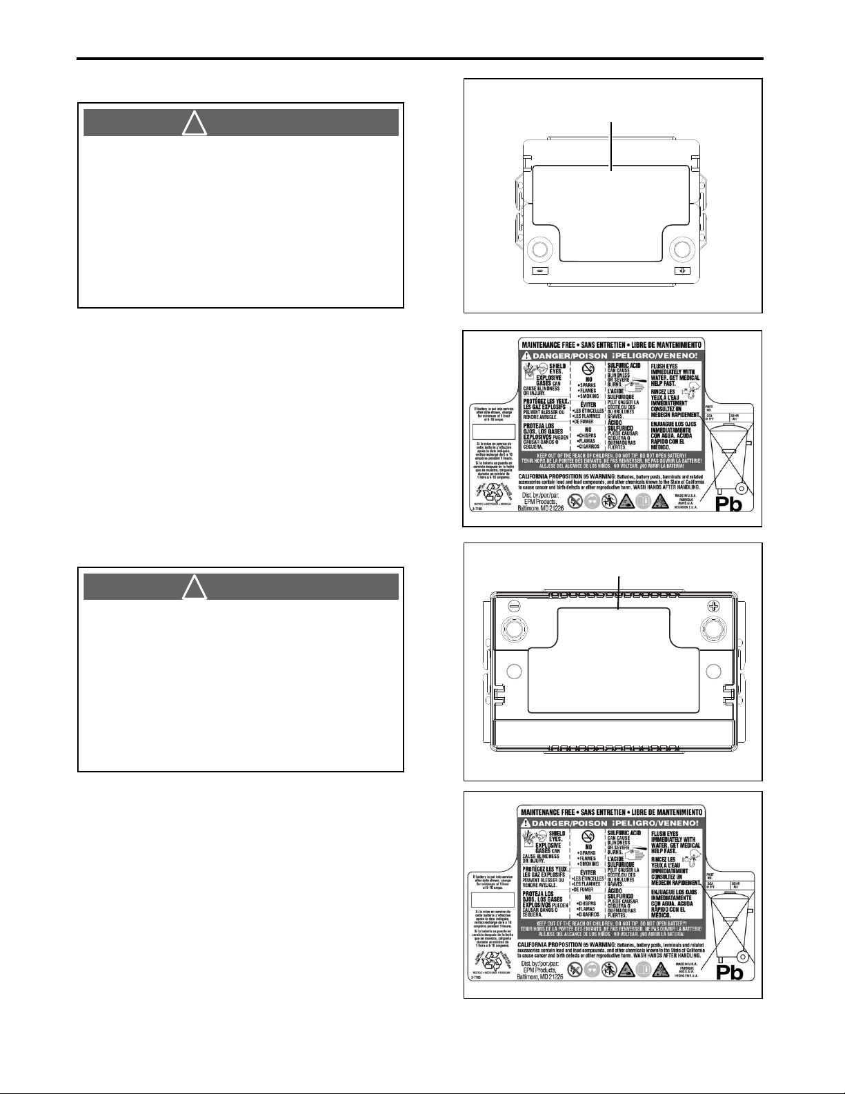
1. SAFETY PRECAUTIONS
(H)
526RMF_410-450
! DANGER
624MF_490
(I)
! DANGER
1A8275-51520_Lx490
(H) 1A8160-51520 (For Lx410/450)
● SHIELD EYES. EXPLOSIVE GASES CAN
CAUSE BLINDNESS OR INJURY.
● NO SPARKS, FLAMES, SMOKING.
● SULFURIC ACID CAN CAUSE BLINDNESS
OR SEVERE BURNS.
● FLUSH EYES IMMEDIATELY WITH WATER.
GET MEDICAL HELP FAST.
● KEEP OUT OF REACH OF CHILDREN. DO
NOT TIP. DO NOT OPEN BATTERY!
540
45
(I) 1A8275-51520 (For Lx490)
● SHIELD EYES. EXPLOSIVE GASES CAN
CAUSE BLINDNESS OR INJURY.
● NO SPARKS, FLAMES, SMOKING.
● SULFURIC ACID CAN CAUSE BLINDNESS
OR SEVERE BURNS.
● FLUSH EYES IMMEDIATELY WITH WATER.
GET MEDICAL HELP FAST.
● KEEP OUT OF REACH OF CHILDREN. DO
NOT TIP. DO NOT OPEN BATTERY!
1A8160-51520_Lx450
650
55
Lx410/450/490 Operator's Manual
1-16
Page 27
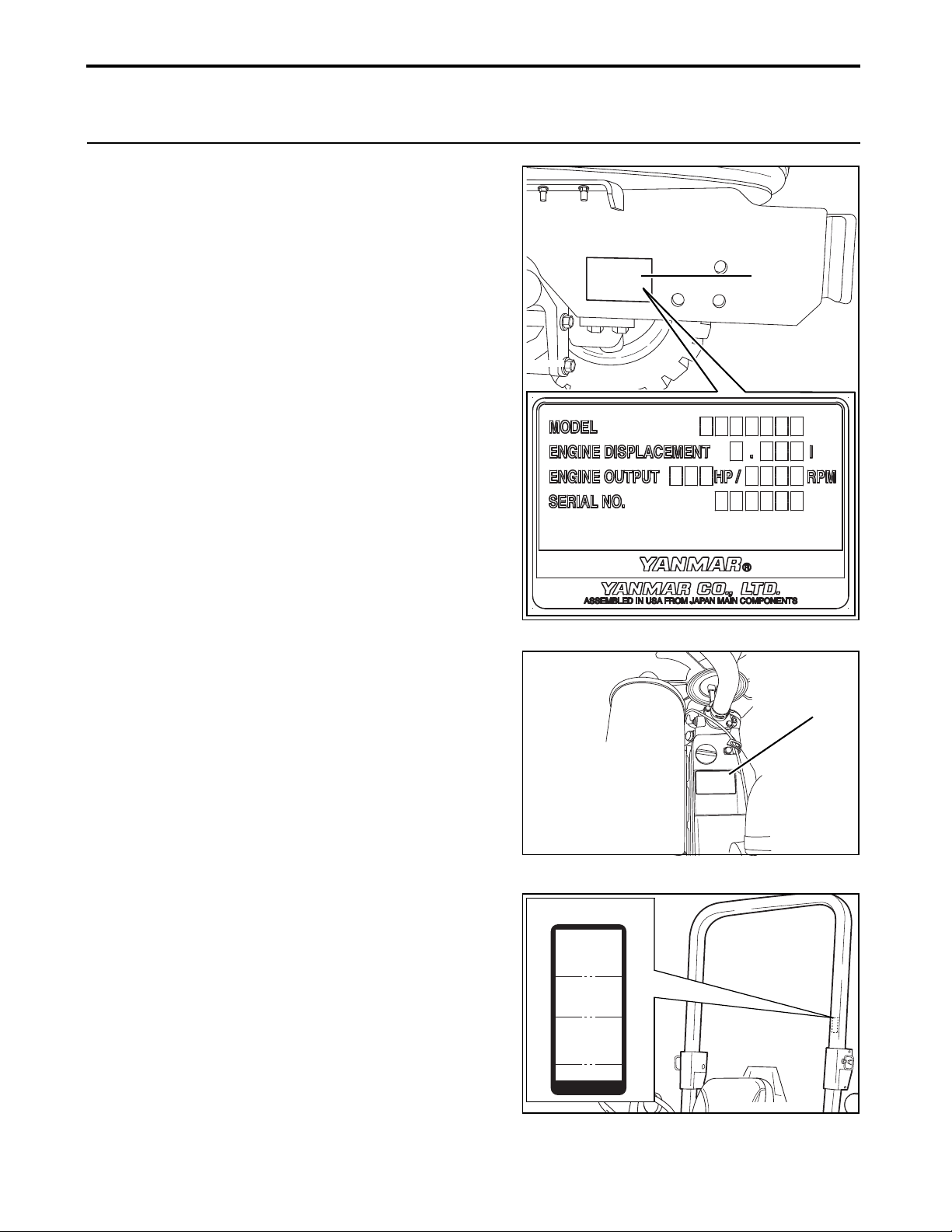
2. SERVICE THE TRACTOR
P1110717
(A)
P1120057
(B)
450_004_ROPS3
1a8250-65821
(C)
2. SERVICE THE TRACTOR
Your Yanmar tractor dealer is committed to provide
reliable and quality services to the tractor. Through the
preceding services, the full performance potential of the
tractor can be realized.
After carefully studying the contents of the Operator's
Manual, the tractor owner/operator can perform certain
regular maintenance work.
●Exercise caution so as not to injure the operator and
other persons.
●Do not attempt to do work that is beyond the owner/
operator capability and knowledge.
When in doubt, always consult YOUR LOCAL YANMAR
TRACTOR DEALER.
For information about servicing, contact YOUR LOCAL
YANMAR TRACTOR DEALER.
For new parts and components and major service work,
contact YOUR LOCAL YANMAR TRACTOR DEALER for
technical assistance.
When ordering a part or component, always provide the
serial numbers of the following to YOUR LOCAL
YANMAR TRACTOR DEALER:
●Tractor
●Engine
●Roll-Over Protective Structure (ROPS)
After accepting delivery of the tractor, immediately find the
serial numbers and enter the numbers into the following table.
●The information in the table must come in handy, if for some
reason, the serial numbers on the tractor are covered,
erased or become illegible.
㪤㫆㪻㪼㫃㪑㪝㪤㪇㪈㪊
㪫㫉㪸㪺㫋㫆㫉㩷㪤㫆㪻㪼㫃㪑
㪣㫏㪋㪈㪇
㪣㫏㪋㪌㪇
㪣㫏㪋㪐㪇
㪫㫉㪸㪺㫋㫆㫉
㪩㪼㪽㪼㫉㪼㫅㪺㪼
㪤㪸㫊㫊
㪋㪃㪇㪇㪊㪅㪌㪣㪙㪪
㩿㪈㪃㪏㪈㪍㪢㪞㪀
㪫㪿㫀㫊㩷㪩㪦㪧㪪㩷㪿㪸㫊
㪹㪼㪼㫅㩷㫋㪼㫊㫋㪼㪻㩷㫀㫅
㪸㪺㪺㫆㫉㪻㪸㫅㪺㪼㩷㫎㫀㫋㪿
㪪㪘㪜㩷㪡㪉㪈㪐㪋㪃
㪦㪪㪟㪘㪑㪉㪐㪚㪝㪩㩷㪧㪸㫉㫋
㪈㪐㪉㪏㩷㪪㫌㪹㫇㪸㫉㫋㩷㪚
㪰㪘㪥㪤㪘㪩㩷㪚㪦㪅㪃㩷㪣㪫㪛
㪦㫊㪸㫂㪸㪃㩷㪡㪸㫇㪸㫅
㪈㪘㪏㪉㪌㪇㪄㪍㪌㪏㪉㪈
2-1
Lx410/450/490 Operator's Manual
Page 28

2. SERVICE THE TRACTOR
450_007_ROPS
(D)
Type/Model Serial No.
Tractor
Engine
Roll-Over Protective
Structure (ROPS)
Date of Purchase
Name of Dealer
(A)Tractor identification plate with tractor serial
number
(B)Engine serial number
(C)Roll-Over Protective Structure (ROPS) model
(D)Roll-Over Protective Structure (ROPS) serial
number
Lx410/450/490 Operator's Manual
2-2
Page 29

3. SPECIFICATIONS
3. SPECIFICATIONS
1. Specifications Table
Model Lx410 Lx450 Lx490
Power Take Off (PTO) Power:
Estimated Average
Maker YANMAR
Model 4TNV88 4TNV88 4TNV84T
Type 4 Cycle Inline, Water-Cooled Diesel
Aspiration Without Turbo Charged Turbo Charged
Number of Cylinders 4 4 4
Bore and Stroke in. (mm)
Engine
Capacities
Dimensions
Weight (with Roll-Over Protective
Structure (ROPS) and R4 Tires)
Total Displacement cu. in. (L) 133.5 (2.189) 133.5 (2.189) 121.7 (1.995)
Gross Power:
EPA Regulation
Net Power hp (kW) Rated Revolution rpm 2700 2700 2600
Maximum Torque ft•lbs (N•m) 94.2 (124.9) 104.4 (141.6) 113.6 (154.2)
Battery 540 CCA 540 CCA 650 CCA
Fuel Diesel Fuel: Ultra Low Sulfur
Fuel Tank US gal (L) 11.9 (45) 11.9 (45) 11.9 (45)
Engine Oil US qt. (L) 5.6 (5.3) 5.6 (5.3) 5.6 (5.3)
Engine Coolant US qt. (L) 5.1 (4.8) 5.1 (4.8) 5.1 (4.8)
Transmission Oil US gal (L) 8.5 (32) 8.5 (32) 8.5 (32)
Front-axle Oil US gal (L) 2.3 (8.8) 2.3 (8.8) 2.3 (8.8)
Overall Length
(with 3-Point Hitch)
Overall Width
(with R4 Tires)
Overall Height
(with Roll-Over Protective
Structure (ROPS), R4 Tires)
Overall Height
(with R4 Tires)
(Top of Steering Wheel)
Wheel Base in. (mm) 74.8 (1900)
Min. Ground Clearance
(with R4 Tires)
Tread
(with R4)
Front in. (mm) 51.7 (1314)
Rear in. (mm) 51.9 (1319)
hp (kW) 30.4 (22.7) 34.3 (25.6) 36.8 (27.5)
3.46 × 3.54
(88 × 90)
hp (kW) 41.3 (30.8) 45.3 (33.8) 48.5 (36.2)
in. (mm) 131.7 (3345)
in. (mm) 69.5 (1764)
in. (mm) 96.1 (2440)
in. (mm) -
in. (mm) 15.5 (393)
lb. (kg) 3585 (1626) 3618 (1641)
3.46 × 3.54
(88 × 90)
- -
3.31 × 3.54
(84 × 90)
3-1
Lx410/450/490 Operator's Manual
Page 30

3. SPECIFICATIONS
Traveling
System
Traveling
System
Hydraulic
Unit
Power Take
Off (PTO)
Ag (R1)
Tire
Clutch Hydrostatic Multi Plate Disk
Steering Hydrostatic Power
Transmission Full Synchro Main, 3 Range
Brake Wet Disk
Minimum Turning Radiu s ft. (m) 9.19 (2.8)
Hydraulic Control System Position Control, Open Center
Pump Capacity (main)
Pump Capacity (steering)
3-Point Hitch Category 1
Max. Lift
Force
System Pressure psi (MPa) 2429 (16.7)
Type Independent
Shaft size 35 mm OD, 6 Splines.
Speed/Engine rpm
Tur f (R3)
Industrial (R4)
Lift Point lb. (kg) 3197 (1450)
24 in. Behind
Lift Point
Front 8 - 16 - 6 ply
Rear 14.9 - 24 - 6 ply
Front 27 × 10.5 - 15 - 4 ply
Rear 44 × 18.00 - 20 - 4 ply
Front 10 - 16.5 - 6 ply
Rear 17.5L - 24 - 6 ply
US gal/min
(L/min)
US gal/min
(L/min)
lb. (kg) 2756 (1250)
563/2700 563/2700 542/2600
540/2592 540/2592 540/2592
9.0 (34.1) 8.6 (32.8)
6.8 (25.6) 6.5 (24.7)
Lx410/450/490 Operator's Manual
3-2
Page 31

2. Traveling Speeds
Range Primary gear lever Range gear lever
F1 1 1 0.968 1.557
F2 1 2 1.345 2.165
F3 1 3 1.720 2.768
F4 2 1 2.254 3.627
F5 2 2 2.388 3.842
F6 2 3 3.320 5.343
F7 3 1 4.246 6.831
F8 3 2 5.562 8.950
F9 3 3 7.115 11.448
F10 4 1 9.895 15.921
F11 4 2 12.652 20.357
F12 4 3 16.576 26.671
R1 1 1 0.965 1.553
R2 1 2 1.342 2.160
R3 1 3 1.716 2.761
R4 2 1 2.248 3.618
R5 2 2 2.382 3.832
R6 2 3 3.312 5.330
R7 3 1 4.235 6.814
R8 3 2 5.549 8.928
R9 3 3 7.098 11.420
R10 4 1 9.871 15.882
R11 4 2 12.621 20.307
R12 4 3 16.535 26.605
3. SPECIFICATIONS
(At rated engine Revolutions Per Minute (rpm))
Lx410/450
Approximately rated speed
mph km/h
NOTE
●The traveling speeds listed above are for when the tire size is R1.
3-3
Lx410/450/490 Operator's Manual
Page 32

3. SPECIFICATIONS
(At rated engine Revolutions Per Minute (rpm))
Lx490
Range Primary gear lever Range gear lever
F1 1 1 0.932 1.499
F2 1 2 1.296 2.085
F3 1 3 1.657 2.666
F4 2 1 2.170 3.492
F5 2 2 2.299 3.699
F6 2 3 3.197 5.145
F7 3 1 4.088 6.578
F8 3 2 5.356 8.619
F9 3 3 6.852 11.024
F10 4 1 9.528 15.331
F11 4 2 12.183 19.603
F12 4 3 15.962 25.683
R1 1 1 0.929 1.495
R2 1 2 1.292 2.080
R3 1 3 1.653 2.659
R4 2 1 2.165 3.484
R5 2 2 2.294 3.690
R6 2 3 3.190 5.132
R7 3 1 4.078 6.562
R8 3 2 5.343 8.597
R9 3 3 6.835 10.997
R10 4 1 9.505 15.293
R11 4 2 12.153 19.555
R12 4 3 15.923 25.620
Approximately rated speed
mph km/h
NOTE
●The traveling speeds listed above are for when the tire size is R1.
Lx410/450/490 Operator's Manual
3-4
Page 33

4. IMPLEMENT CAPACITIES
A3013714
4. IMPLEMENT CAPACITIES
●Prior to delivery, the tractor is subjected to the load tests described below.
●The tests are designed to ensure the tractor performs safely and to specification when subjected to various
loads and stresses.
●Genuine implements approved by Yanmar are used.
IMPORTANT
●Use only implements approved by YOUR LOCAL YANMAR TRACTOR DEALER.
●A ll imple m en ts us ed mu st confo rm to th e ap pr ov ed spe cifications, per below.
●Using unapproved implements can result in malfunction, failure and damage to the tractor.
●The preceding action can also increase the possibility of injury to the operator or other people. The Yanmar
warranty does not cover any malfunction or failure that results from the use of an unapproved implement.
.
Lower Link End
Maximum Lifting
Capacity
W
0
lb. 3197
kg 1450 500 2500
Implement Weight
and Size
W
1
As specified in the list
shown in the next page
Maximum Drawbar Load
W
2
1102 5512
Trailer Loading Weight
Maximum Capacity
W
3
W0
W1
W2 W3
4-1
Lx410/450/490 Operator's Manual
Page 34

Implement Description Unit Maximum Amount
Trailer
Rotary-Cutter
Mower
Finish Mower
Rotary Tiller
Box Scraper
Rear Blade
Landscape Rake
Loader
Backhoe
4. IMPLEMENT CAPACITIES
Load Capacity lb. (kg) 5512 (2500)
Drawbar Load lb. (kg) 1102 (500)
Cutting Width in. (mm) 72 (1829)
Weight lb. (kg) 602 (273)
Cutting Width in. (mm) 72 (1829)
Weight lb. (kg) 600 (272)
Tilling Width in. (mm) 74 (1880)
Weight lb. (kg) 800 (363)
Cutting Width in. (mm) 84 (2134)
Weight lb. (kg) 630 (286)
Cutting Width in. (mm) 84 (2314)
Weight lb. (kg) 294 (133)
Cutting Width in. (mm) 84 (2134)
Weight lb. (kg) 274 (124)
Lift Capacity (at Pivot) lb. (kg) 2493 (1133)
Overhang (Pivot ~ Front Tire Center) in. (mm) 46.3 (1176)
Weight (without Bucket) lb. (kg) 828 (375)
Digging Depth ft. (mm) 8.5 (2550)
Weight lb. (kg) 1650 (748)
Lx410/450/490 Operator's Manual
4-2
Page 35

5. NAMES AND FUNCTIONS OF COMPONENTS
(22)
450_P1080900
450_000_Lx
(1)
(2) (3) (4)
(5)
(6)
(7)
v30_w_c5_n2
(8)
(9) (9)
(8)
(10) (11)
(12)
(13)
(15)
(16)
(17)(17)
(16)
(19)
(18)
(14)
(20)
v30_w_c5_P1090034
(21)
5.
NAMES AND FUNCTIONS OF COMPONENTS
1. Overview
■ Names of Main Components
(1) Front tires
(2) Headlights
(3) Side lights
(4) Hood
(5) Roll-Over Protective Structure (ROPS)
(6) Fender
(7) Rear tires
(8) Tail lights
(9) Turn signal/hazard lights
(10)Fuel filler cap
(11)Slow Moving Vehicle (SMV) emblem
(12)Top link
(13)Top link hook
(14) Lift link right
(15)Power Take Off (PTO) shaft
(16)Implement sliding stabilizer
(17)Lower links
(18)Adjustment box
(19)Drawbar
(20)Lift link left
(21)Operator seat back pocket
(22)Operator seat
5-1
Lx410/450/490 Operator's Manual
Page 36

5. NAMES AND FUNCTIONS OF COMPONENTS
v30wc5‑n2P1090034
(A)
450P1080900
(c)
(A)
(a)
(b)
(d)
PRESS
450P1090030
(e)
(f)
■ Functions of Main Components
(1) Front tires
Support the front part of the tractor and allows the
tractor to roll.
(2) Headlights
Provide illumination in front of the tractor.
(3) Side lights
Provide illumination at the side of the tractor.
(4) Hood
Covers and protects the engine.
(5) Roll-Over Protective Structure (ROPS)
Protect the operator in the event of an accident such
as a roll over.
(6) Fender
Keeps mud away from the operator.
(7) Re a r ti re s
Supports the back part of the tractor and allows the
tractor to roll.
(16)Implement sliding stabilizer
Component that vertically stabilizes a hitched
implement.
(17)Lower links
Connects and holds an implement.
(18)Adjustment box
Raise or lower to the desire height of the implement.
(19)Drawbar
Use to pull/tow an implement.
(20)Lift link left
Non-adjustable link.
(21)Operator seat back pocket
Hold the Operator's Manual.
(8) Tail lights
Provide illumination at the rear of the tractor.
(9) Turn signal/hazard lights
Use to warn people that tractor is about to turn left or
right. Use to warn people of an emergency situation.
(10)Fuel filler cap
Where the fuel nozzle is inserted to fill up the fuel
tank.
(11)Slow Moving Vehicle (SMV) emblem
Identify the tractor as a slow moving vehicle to other
motorists.
(12)Top link
Use to adjust angle or position of an implement.
(13)Top link hook
Hold the top link when the top link is not in use.
(14)Lift link right
Adjustable link.
(15)Power Take Off (PTO) shaft
Transmit rotational force from the tractor to an
implement.
Lx410/450/490 Operator's Manual
(A)Operator seat back pocket
(22)Operator seat
Sits the operator and from where the operator can
easily control the tractor instruments.
(A)Operator seat
(a) Operator seat firmness suspension knob
(b) Operator seat suspension stroke adjustment
(c) Operator seat forward and backward lever
(d) Retractable seatbelt
(e) Retractable seatbelt quick release bu tton
(f) Backrest lever
5-2
Page 37

5. NAMES AND FUNCTIONS OF COMPONENTS
40 IMG_4473
(29)
(30)
(31)
v30_w_c5_n1_P1090027
(21)
(22)
(23)
(24)
(25)
(26)
(27)
(28)
(8)
(7)
(9)
(10)
(11)
(12)
(13)
(14)
(14)
(15)
(16)
(17)
(18)
(19)
(20)
P5-3 top view _1
(1) (2) (3)
(4) (5) (6)
2. Operator Station Controls
■ Names of Components
(1) Clutch ped al
(2) Forward/N/reverse lever
(3) Hazard lights bu tton switch
(4) Headlights, side lights and tail lights/turn signal
switch
(5) Throttle control lever
(6) Accelerator pedal
(7) Starter key switch
(8) Implement control lever
(9) Implement control lever lock
(10) Power Take Off (PTO) switch
(11) Console box
(12) Position stop knob
(13)3-point hitch control lever
(14) Operator seat arm rest
(15)12V DC outlet
(16)Cup holder
(17)Range gear lever
(18)2WD/4WD lever
(19)Primary gear lever
(20)Tilt pedal
(21)Operator seat
(22)Backrest lever
(23)Operator seat firmness suspension knob
(24)Operator seat suspension stroke adjustment
knob
(25)Hydraulic flow control/stop knob
(26)Differential lock pedal
(27)Operator seat forward and backward lever
(28)Retractable seatbelt
(29)Brake pedal connector lock
(30)Brake pedals
(31) Parking brake lock lever
5-3
Lx410/450/490 Operator's Manual
Page 38

5. NAMES AND FUNCTIONS OF COMPONENTS
v30_w_c5_P34-n1_P1080277
(A)
12 P1080942
(b)
(c)
(A)
(a)
(A)
(a) (b)
v30_w_c5_P34-n4_P1080974
■ Function of Components
(1) Cl u tc h pe d al
Engages or disengages the rotational force of the engine
to the transmission.
(A)Clutch pedal
(2) Forward/N/reverse lever
Change the direction of the tractor's movement.
(A) Forward/N/reverse lever
(a) Forward
(b) N (neutral)
(c) Reverse
(3) Hazard lights button switch
Turn ON or OFF the hazard lights.
(A)Hazard lights button switch
(a) ON
(b) OFF
Lx410/450/490 Operator's Manual
5-4
Page 39

5. NAMES AND FUNCTIONS OF COMPONENTS
v30_w_c5_P34-n3_P1080271
(A)
OFF
P1080271 8
(A)
(a)
(b)
1
0
5
5
2
2
15_ IMG 4500
(A)
(a)
(b)
Accelerator_pedal
(A)
(4) Headlights, side lights and tail lights/turn signal
switch
● Position 1: - All lights OFF
● Position 2: - All lights ON
Headlights: Low beam
● Position 3: - All lights ON
Headlights: High beam
(A)Headlights, side lights and tail lights/turn signal
switch
(5) Turn Signals
(A)Turn signal lever
(a) Push the turn signal lever upward: to signal an
intention to turn left.
(b) Push the turn signal lever downward: to signal an
intention to turn right.
(6) Throttle control lever
Increases or decreases the engine speed (Revolutions
Per Minute (rpm)) rate.
(A)Throttle control lever
(a) Increase the engine speed (Revolutions Per Minute
(rpm))
(b) Decrease the engine speed (Revolutions Per Minute
(rpm))
(7) Accelerator pedal
Increases or decreases the engine speed Revolutions Per
Minute (rpm) rate.
(A)Accelerator pedal
5-5
Lx410/450/490 Operator's Manual
Page 40

5. NAMES AND FUNCTIONS OF COMPONENTS
45007018 Starter
(A)
450_009_ICLever
(A)
450_009_ICLLock
(A)
(a)
(b)
14-13_PTO_SW_1
(A)
(a) (b)
(8) Starter key switch
Start and/or shut off the engine.
(A)Starter key switch
(9) Implement control lever
Control the loader.
(A)Implement control lever
(10)Implement control lever lock
Lock the implement control lever to the N (neutral)
position.
(A)Implement control lever lock
(a) Locked position
(b) Unlocked position
(11)Power Take Off (PTO) switch
Turn ON or OFF the Power Take Off (PTO).
(A)Power Take Off (PTO) switch
(a) ON position
(b) OFF position
Lx410/450/490 Operator's Manual
5-6
Page 41

5. NAMES AND FUNCTIONS OF COMPONENTS
Console_box
(A)
㪈
㪉
㪊
㪋
㪌
㪍
㪈㪘㪏㪉㪌㪇㪄㪍㪌㪋㪎㪇
3P_hitch_lever_3
(A)
㪈
㪉
㪊
㪋
㪌
㪍
㪈㪘㪏㪉㪌㪇㪄㪍㪌㪋㪎㪇
PositionStopKnob_4
(A)
v30_w_c5_P40-n1_IMG 4466
(A)
(12)Console box
The place where the Operator's Manual is kept.
(A)Console box
(13)3-point hitch control lever
Control the height of the lower links.
(A)3-point hitch control lever
(14)Position stop knob
Hold the 3-point hitch control lever to a specific position.
(A)Position stop knob
(15)Operator seat arm rest
Use to rest the operator's arms.
(A)Operator seat arm rest
5-7
Lx410/450/490 Operator's Manual
Page 42

5. NAMES AND FUNCTIONS OF COMPONENTS
12V DC
(A)
Cup_holder01
(A)
IMG_4479 2
(A)
(16)12V DC outlet
Outlet used for 12V DC supply.
(A)12V DC outlet
NOTE
● Avoid using the 12V DC outlet as cigarette lighter.
(17)Cup holder
The place where a cup is held.
(A)Cup holder
(18) Range gear lever
Change the range gear setting.
(A)Range gear lever
1
N
2
3
N
4
Lx410/450/490 Operator's Manual
5-8
Page 43

5. NAMES AND FUNCTIONS OF COMPONENTS
IMG_4479 3
(A)
(a)(b)
v30_w_c5_P-35-n2_IMG 4480
(A)
v30_w_c5_P39-n1_P1080277
(A)
(a)
(b)
v30_w_c5_n1_P1090027
(A)
(19)2WD/4WD lever
Engages or disengages the 4-wheel drive.
(A)2WD/4WD lever
(a) Engage position
(b) Disengage position
(20)Primary gear lever
Shift the primary gear.
(A)Primary gear lever
1
N
2
3
N
4
(21)Tilt pedal
Change the inclination angle of the steering wheel.
(A)Tilt pedal
(a) Locked position
(b) Unlocked position
(22)Operator seat
Station where the operator sit to operate the tractor.
(A)Operator seat
5-9
Lx410/450/490 Operator's Manual
Page 44

5. NAMES AND FUNCTIONS OF COMPONENTS
PRESS
32 P109030
(A)
(b)
(a)
33 P1080900
(A)
(a)
(b)
(A)
34 P1080900
(a)
(b)
35 P1080310
(A)
(a)
(b)
(23)Backrest lever
Adjust the inclination of the backrest.
(A)Backrest lever
(a) Unlock the operator seat backrest
(a) Lock the operator seat backre st
(24)Operator seat firmness suspension knob
Adjust the firmness or softness of the operator seat.
(A)Operator seat firmness suspension knob
(a) Firmer
(b) Softer
(25)Operator seat suspension stroke adjustment
knob
Adjust the height of the operator seat.
(A)Operator seat suspension stroke adjustment knob
(a) Decrease
(b) Increase
(26)Hydraulic flow control/stop knob
Increases/decreases and closes/opens the hydraulic
circulation of the 3-point hitch.
(A)Hydraulic flow control/stop knob
(a) Close - stop
(b) Open
Lx410/450/490 Operator's Manual
5-10
Page 45

5. NAMES AND FUNCTIONS OF COMPONENTS
(A)
36 P1080310a
(b)
(a)
37 P1080900
(A)
(a)
(b)
45005228
(A)
39 IMG_44733
(A)
(a)
(b)
(27)Differential lock pedal
Engages or disengages the differential lock.
(A)Differential lock pedal
(a) Lock position
(b) Unlock position
(28)Operator seat forward and backward lever
Adjust the operator seat to the forward or backward
position.
(A)Operator seat forward and backward lever
(a) Unlock
(b) Lock
(29)Retractable seatbelt
Keep the operator safe while operating the tractor.
(A)Retractable seatbelt
(30)Brake pedal connector lock
Locks the left and the right brake pedals together.
(A)Brake pedal connector lock
(a) Locked position
(b) Unlocked position
5-11
Lx410/450/490 Operator's Manual
Page 46

5. NAMES AND FUNCTIONS OF COMPONENTS
40IMG 4473
(A)
4 IMG_4473a
(A)
(a)
(b)
(31)Brake pedals
Reduce the speed and stop the tractor.
(A)Brake pedal
(32)Parking brake lock lever
Engage the parking brake.
(A)Parking brake lock lever
(a) Lock
(b) Unlock
Lx410/450/490 Operator's Manual
5-12
Page 47

5. NAMES AND FUNCTIONS OF COMPONENTS
42 P1080979
(1) (2)
(4)
(5)(6)(8)
(9)
(10)
(11)
(2)
(7)
(3)
3. Instrument Panel
1
5
0
1
0
5
0
2
5
2
0
3
(1) Forward/N/reverse lever N (neutral) indicator
light
Indicates the forward/N/reverse lever is in the N
(neutral) position.
(2) Turn signal/hazard indicator lights
Indicates when the corresponding turn signal/hazard
lights is illuminated/flashing.
NOTE
● The hazard lights remain flashing even when the
starter key switch is in the OFF position.
● Allowing the turn signal/hazard lights to flash for
an extended period can lead to loss of battery
voltage.
(3) Power Take Off (PTO) indicator light
Power Take Off (PTO) indicator light illuminates
when Power Take Off (PTO) switch is in the ON
position.
(4) Parking brake indicator light
Indicate parking brake is engaged.
(5) Coolant temperature gauge
Indicate the current coolant temperature.
If the needle points to within the red zone, the engine
is too hot.
IMPORTANT
● Decrease the load on the tractor:
• when the pointer on the coolant temperature
gauge reaches the abnormally high
temperature
• when the pointer on the coolant temperature
gauge jumps up or rapidly increases
● To lower the coolant temperature:
• idle the engine until the reading on the gauge
falls to the green zone
• shut off the engine
• allow the engine to cool down
● After the preceding actions, check the following:
• the coolant level in the radiator and in the
reserve tank are adequate
• the radiator and radiator screen are free from
dust deposits
• the alternator/fan belt tension is correct
NOTE
● In some cases, even when the parking brake lock
lever appears to be in the "LOCKED" position, the
parking brake itself may not be actually securely
locked.
For details, see “Chapter 14. PERIODIC SERVICE”
on page 14-1.
● If the pointer on the coolant temperature gauge
enters the red zone or the reading rapidly
5-13
increases again:
• shut down the engine
• immediately contact YOUR LOCAL YANMAR
TRACTOR DEALER for technical assistance
Lx410/450/490 Operator's Manual
Page 48

5. NAMES AND FUNCTIONS OF COMPONENTS
(6) Hour meter
Indicate the total accumulated operating hours.
(7) Tachometer
Indicates the current engine speed in increments of
100 Revolutions Per Minute (rpm).
(8) Fuel gauge
Indicates how much fuel is in the fuel tank.
(9) Glow plug indicator light
Indicates the engine is still being preheated.
(10)Alternator/Battery charging light
Illuminates when:
● The starter key switch is in the ON position and the
engine is not running.
● The alternator/battery charging circuit is out of
order.
IMPORTANT
● While the engine is running, an illuminated
alternator/battery charging light indicates the
power generated by the alternator is too low.
• fully push the throttle control lever forward
• increase the engine speed
● If the light still remains illuminated:
• immediately shut down the engine
• contact YOUR LOCAL YANMAR TRACTOR
DEALER for technical assist ance
(11)Engine oil pressure warning light
The engine oil pressure warning light remains
illuminated when:
● The starter key switch is in the ON position and the
engine is not running.
● The engine oil pressure is abnormal.
IMPORTANT
● While the engine is running, an illuminated engine
oil pressure warning light indicates the engine oil
pressure is too low.
• immediately shut down the engine
• contact YOUR LOCAL YANMAR TRACTOR
DEALER for technical assist ance
Lx410/450/490 Operator's Manual
5-14
Page 49

6. PRE-OPERATION CHECK
6. PRE-OPERATION CHECK
1. Pre-Operation Check
1. Check the tractor for damage, excessive wear,
cracks, missing parts, leaks, exposed wiring and
any other problems.
2. Check the joints and connections for tight fit.
3. Make sure all the lights illuminates and functions
correctly.
4. Make sure all the safety alert decals are in correct
positions.
5. Correct any problem detected.
6. Contact YOUR LOCAL YANMAR TRACTOR
DEALER for problems that can not be solve.
Avoid operating the tractor when a problem has been
indicated.
2. Precautions Before Operation
1. Always be aware of the performance limitations of
the tractor.
2. Operate only within the limitations.
3. When operating the tractor, always maintain a
“SAFETY FIRST!” approach.
4. Prevent Damage to Plastic Surfaces and Painted Surfaces
1. To prevent scratches and discolorations on the
surfaces:
• Wipe the tractor only after thoroughly washing
the surfaces.
2. Chemical substances such as pesticid es ca n
damage the plastic surfaces and painted
surfaces.
• Avoid spraying chemical substances on and near
the tractor.
3. Avoid spilling diesel fuel onto the tractor.
• Diesel fuel can damage the plastic surfaces and
painted surfaces.
• Immediately wipe off spilled diesel fuel.
3. Routine Checks
1. Check the safety features.
2. Check the tire air pressure.
3. Make sure the remaining diesel fu el is sufficie nt
for the intended operation.
4. Check the engine oil level.
5. Check the transmission hydraulic oil level.
6. Check the coolant level.
7. Remove grass clippings and debris from the
tractor.
8. Clean the air filter element.
9. Check any liquid leaks such as oil, coolant and
fuel.
10.Check the radiator for possible blockage.
11.Check the retractable seatbelt for any problem/s.
12.Check Roll-Over Protective Structure (ROPS) for
any problem/s.
13.Contact YOUR LOCAL YANMAR TRACTOR
DEALER for technical assistance.
6-1
Lx410/450/490 Operator's Manual
Page 50

7. OPERATE THE ENGINE
! WARNING
! WARNING
7. OPERATE THE ENGINE
1. Start the Engine
Always run or idle the engine in a
well ventilated area:
● To prevent serious illness or
death, caused by the colorless
and odorless carbon monoxide
emitted by the engine.
● Always remain seated on the operator seat when:
• starting the engine
• operating the levers and controls
● Before starting the engine, always ensure:
• the primary gear lever is in the N (neutral)
position
• range gear lever is in the N (neutral) position
• forward/N/reverse lever is in the N (neutral)
position
• the parking brake lock is engaged
• Power Take Off (PTO) switch in the OFF position
● Always keep the retractable seatbelt fastened:
• whenever the Roll-Over Protective Structure
(ROPS) is in the unfolded "up" position and
locked securely
● Start the engine only with the starter key switch.
• avoid starting the engine by short circuiting
across the starter solenoid terminals with a
jumper wire
• by bypassing the safety start switch
● Before operation, ensure all the safety features
are functioning correctly. Make correctio ns as
necessary.
● Always observe the following precautions
when starting the engine.
• before starting and during running the
engine:
• always drive the tractor outside or to a
well ventilated area
• to prevent serious illness or death caused
by the carbon monoxide contained in the
exhaust of the engine
● To prevent explosions, always use only
diesel fuel to start the engine.
● In cold weather, use the Intake Air Heater
System to help the engine start more
smoothly.
● To prevent injury or death from a runaway
tractor:
• avoid starting the engine by short circuiting
across the starter solenoid terminals with a
jumper wire
• the tractor starts in gear and begins to move
when the normal circuitry is bypassed
● When starting the engine:
• always remain seated on the operator seat
with the transmission in the N (neutral)
position
• do not under any circumstances attempt to
start the engine while the operator is still on
the ground
Lx410/450/490 Operator's Manual
NOTE
● When the temperature is below 40°F (5°C), for
details, see "Start the Engine in Cold Weather"
on page 7-8.
7-1
Page 51

7. OPERATE THE ENGINE
v30_w_c5-n2
(A)
(a)
(b)
34 P1080900
(A)
(a)
(b)
33 P1080900
(A)
(a)
(b)
1. Open/Close the Fuel Shut-Off Valve
1. To open the fuel shut-off valve: Turn the fuel shutoff valve to the ON (open) position.
2. To close the fuel shut-off valve: Turn the fuel
shut-off valve to the OFF (closed) position.
(A)Fuel shut-off valve
(a) OFF (closed) position
(b) ON (open) position
2. Get on the Tractor
1. Always use the step located on the left side of the
tractor to climb on the tractor.
2. Sit on the operator seat.
(A)Operator seat suspension stroke adjustment
knob
(a) Decrease
(b) Increase
4. Operator seat firmness suspension knob
• Turn the operator seat firmness suspension knob
clockwise to make the operator seat suspension
firmer.
• Turn the operator seat firmness suspension knob
counterclockwise to make the operator seat
suspension softer.
3. Adjust the Operator Seat
1. Sit on the operator seat.
2. Operator seat forward and backward lever.
• Move the operator seat forward and backward
lever to set the optimal position.
• the operator seat can be adjusted to 14
different positions in 0.47 in. (12 mm)
increments
3. Operator seat suspension stroke adjustment knob
• While the operator is sitting on the operator seat:
• turn the operator seat suspension stroke
adjustment knob clockwise to decrease the
stroke (minimum: 1.57 in. (40 mm))
• turn the operator seat suspension stroke
adjustment knob counterclockwise to increase
the stroke (maximum: 3.15 in. (80 mm))
7-2
(A)Operator seat firmness suspension knob
(a) Firmer
(b) Softer
Lx410/450/490 Operator's Manual
Page 52

7. OPERATE THE ENGINE
PRESS
32 P1090030
(A)
(a)
(b)
37 P1080900b
(b)
(a)
(c)
(d)
(A)
! WARNING
! CAUTION
5. Backrest lever
• Unlock the backrest lever to set the backrest
inclination to a position that is the most suitable
for driving.
(A)Backrest lever
(a) Unlock the operator seat backrest
(b) Lock the operator seat backre st
NOTE
While sitting:
● Make sure the control levers and knobs can be
comfortably operated.
● Readjust the operator seat position as
necessary.
4. Fasten the Retractable Seatbelt
● Always keep the retractable seatbelt
fastened:
• while operating the tracto r wi th the RollOver Protective Structure (ROPS) in the
unfolded "up" position
● The preceding action reduces the possibility
of injury or death in the event of an accident
such as an overturn or roll over.
● Do not under any circumstances use the
retractable seatbelt when operating the
tractor:
• without the Roll-Over Protective Structure
(ROPS)
• with the Roll-Over Protective Structure
(ROPS) in the folded "down" position
1. Pull out the retractable seatbelt from the retracted
position located on the right side of the operator
seat.
2. Fasten the retractable seat be lt to th e bu ckle
located on the left side of the operator seat.
(A)Operator seat forward and backward lever
(a) Toward the front
(b) Toward the rear
(c) Unlock
(d) Lock
NOTE
● Do not twist the retractable seatbelt.
3. Adjust the retractable seatbelt to the suitable
length.
NOTE
● Release the retractable seatbelt by pressing the
retractable seatbelt quick release button.
● Hold the retractable seatbelt with the right
hand when pressing the retractable seatbelt
quick release button.
● The retractable seatbelt flies to the right
which is highly dangerous.
Lx410/450/490 Operator's Manual
7-3
Page 53

7. OPERATE THE ENGINE
4500528
(A)
(B)
! WARNING
41 IMG_4473c
(A)
(b)
(a)
4 IMG_4473a
(A)
(B)
(C)
v30_w_c5-P35_n2_IMG_4480
(A)
(A)Retractable seatbelt
(B)Buckle
● Positioning the retractable seatbelt far away
from the operator's abdominal area can be
dangerous in the event of an accident.
● Always ensure the retractable seatbelt is in
the lowest possible position relative to the
operator's abdominal area.
● The retractable seatbelt must be used only by
the operator.
● Do not under any circumstances use the
retractable seatbelt for two or more persons.
● Do not under any circumstances use the
retractable seatbelt to hold an object to the
operator's body.
5. Lock the Brake Pedals
1. Release the left and right brake pedals.
2. Move counterclockwise the brake pedal
connector lock to lock together the left and right
brake pedals.
6. Lock and Set the Parking Brake
1. Use the brake pedal connector lock to connect
the left and right brake pedals together.
2. Depress the brake pedals fully.
3. While depressing the brake pedals fully, pull up
the parking brake lock lever to lock securely.
4. Remove the foot from the brake pedals.
5. Make sure the parking brake is securely locked.
(A)Brake pedal connector lock
(B)Brake pedals
(C)Parking brake lock lever
7. Perform the Rest of the Operations
1. Move the primary gear lever to the N (neutral)
position.
2. Move the range gear lever to the N (neutral)
position.
3. Move the forward/N/reverse lever to the N
(neutral) position.
4. Push down Power Take Off (PTO) switch to OFF
position.
(A)Brake pedal connector lock
(a) Locked position
(b) Unlocked position
7-4
(A)Primary gear lever
Lx410/450/490 Operator's Manual
Page 54
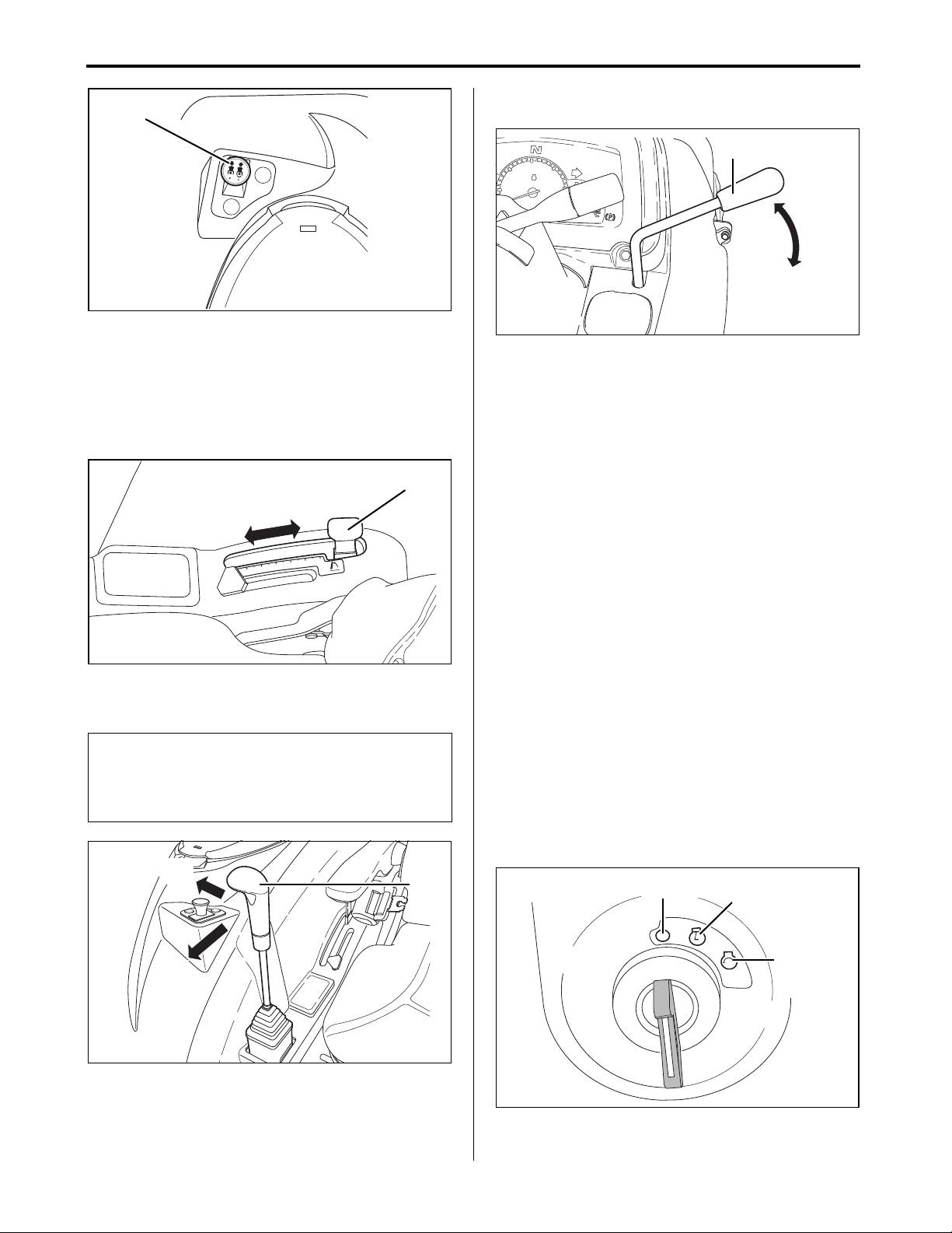
7. OPERATE THE ENGINE
45007017
(B)
㪈
㪉
㪊
㪋
㪌
㪍
㪈㪘㪏㪉㪌㪇㪄㪍㪌㪋㪎㪇
3P_hitch_lever_3
(a)
(b)
(A)
450_009_ICLever2
(A)
(a)
(b)
5
1
1
0
0
5
5
2
2
15 IMG_4500
(A)
(a)
(b)
450070118 Starter
(A)
(B)
(C)
(B)Power Take Off (PTO) switch
5. Push the 3-point hitch control lever forward to
lower any attached implements to the ground.
6. The preceding action prevents the tractor from
suddenly rearing up during the starting of the
engine.
7. Push the throttle control lever forward from the
slow idle position to the 1/3 to 1/2 fast positions.
(A)Throttle control lever
(a) To increase the engine speed, push the throttle
control lever forward.
(b) To decrease the engine speed , pull the throttle
control lever backward.
8. Insert the Key into the Starter Key
Switch and Turn the Key to the ON
Position
OFF position:
The engine does not run.
ON position:
The engine oil pressure warning light and the
(A)3-point hitch control lever
(a) Lowest position
(b) Highest position
alternator/battery charging light illuminates. The glow
plugs indicator light illuminates for 15 seconds, for
Lx410/450 models. Air heater indicator light
illuminates for 15 seconds for Lx490 model.
NOTE
● If the tractor is equipped with the implement
control valve, use the implement control lever to
lower any attached implements to the ground.
START position:
● The starter turns the flywheel to run the engine.
● The engine begins to run.
● Once the engine is running, release the starter key
switch.
(A)Implement control lever
(a) Lower the implement
(b) In levelled position
Lx410/450/490 Operator's Manual
(A)OFF position
(B)ON position
(C)START position
7-5
Page 55

7. OPERATE THE ENGINE
0
0
0
0
5
5
5
1
1
2
2
3
42 P1080979
(B)(A)
(C)
(D)
(E)
v30_w_c5-P34_n1_P1080277
(A)
450070118 Starter
(A) (B)
(C)
9. Check the Lights on the Instrument
Panel
After the key is turned to the ON position:
● The parking brake indicator light turns ON if the
parking brake is engaged.
● The engine oil pressure warning light turns ON.
● The alternator/battery charging light turns ON.
(A)Neutral indicator light
(B)Parking brake indicator light
(C)Glow plug indicator light for Lx410/Lx450
model
Air heater indicator light for Lx490 model
(D)Alternator/Battery charging light
(E) Engine oil pressure warning light
4. Depress the clutch pedal fully.
(A)Clutch pedal
5. Turn and hold the key to the START position.
6. After the engine has successfully started, release
the key.
NOTE
● If the key is released before the engine started:
• wait until both the starter and engine stop
rotating before trying to start the tractor again
NOTE
● The engine oil pressure light turns OFF within 5
seconds after the engine has started.
● The alternator/battery charging light turns OFF
within 10 seconds after the engine is started.
● If the neutral indicator light fail to turn on the
forward/N/reverse lever is engaged.
IMPORTANT
● If the engine oil pressure light fails to turn OFF
within 5 seconds after the engine is started:
• shut off the engine and check for the cause.
● If no specific cause is detected, but a problem
still persists:
• contact YOUR LOCAL YANMAR TRACTOR
DEALER for technical assist ance
1. Turn the starter key switch to the ON posit ion .
2. Energize the glow plug for 15 seconds to allow
easy starting of the engine.
3. The glow plug indicator light is turned OFF after
15 seconds.
(A)OFF position
(B)ON position
(C)START position
IMPORTANT
● Continuous activation of the starter for more than
20 seconds can damage the starter.
● If the engine fails to start within 20 seconds,
discontinue activating the starter.
● Wait for 2 minutes before trying to restart the
engine.
7. Release the clutch pedal slowly.
8. After the engine has started, warm up the engine
for 5 minutes at 1200 to 1500 Revolutions Per
Minute (rpm) without any load.
7-6
Lx410/450/490 Operator's Manual
Page 56

7. OPERATE THE ENGINE
5
1
1
0
0
5
5
2
2
15 IMG_4500b
(A)
(B)
4 IMG_4473a
10.Warm Up the Engine in Cold Weather
1. In cold weather, warm up the engine for longer
than 5 minutes so the hydraulic system can
operate at peak performance.
2. Warm up for a period as specified in the tabl e
below.
Temperature (°F (°C)) Warming-up Time (min.)
Over 32 (0) At least 5
32 to 14 (0 to –10) 5 to 10
14 to –4 (–10 to –20) 10 to 15
Below –4 (–20)
NOTE
● The engine may run slightly louder and emit pale
blue exhaust during warm up.
• the preceding state is normal
• the amount of pale blue exhaust varies
depending on the ambient temperature
● Idling the engine for a long time wastes fuel and
causes carbon accumulation in the engine.
More than 15
11.Idle the Engine
NOTE
● Avoid idling the engine for a long time.
● Prolong idling wastes fuel and causes carbon to
build up in the engine.
1. Pull the throttle control lever backward to the slow
idle (975 Revolutions Per Minute (rpm)) position.
2. Engage the parking brake securely, for details,
see "6. Lock and Set the Parking Brake" on page
7-4.
(A)Throttle control lever
(B)Parking brake lock lever
Lx410/450/490 Operator's Manual
7-7
Page 57

7. OPERATE THE ENGINE
! WARNING
v30_w_c5pP35_n2_IMG_4480
(A)
1
3
4
N
N
2
IMG_4479 2
(A)
P1080941 15
(A)
14-13_PTO_SW_2
(A)
(a)
2. Start the Engine in Cold Weather
1. In case the tractor is operated at a temperature
lower than 0°F (-18°C), the engine oil and/or
transmission hydraulic oil heater can be installed
in the tractor.
2. For information about the engine oil and/or
transmission hydraulic oil heater, contact YOUR
LOCAL YANMAR TRACTOR DEALER.
3. Turn the starter key switch to ON position.
4. Wait for 15 seconds.
5. After the glow plug indicator light goes out, start
the engine.
3. Shut Off the Engine
1. Shut off the engine by:
• Depress the clutch pedal fully.
• Depress both brake pedals.
NOTE
● Make sure the brake pedals are connected
together.
3. Move the range gear lever to the N (neutral)
position.
(A)Range gear lever
4. Move the forward/N/reverse lever to the N
(neutral) position.
● Always depress the brake pedals fully.
2. Move the primary gear lever to the N (neutral)
position.
(A)Primary gear lever
(A)Forward/N/reverse lever
5. Push down Power Take Off (PTO) switch to
(OFF) position.
(A)Power Take Off (PTO) switch
(a) OFF position
7-8
Lx410/450/490 Operator's Manual
Page 58

7. OPERATE THE ENGINE
㪈
㪉
㪊
㪋
㪌
㪍
㪈㪘㪏㪉㪌㪇㪄㪍㪌㪋㪎㪇
3P_hitch_lever_3
(a)
(b)
(A)
450_009_ICLever3
(A)
(a)
5
1
1
0
0
5
5
2
2
15 IMG_4500b
(A)
3017808
(A)
(a)
6. Push the 3-point hitch control lever forward to
lower any implements to the ground.
(A)3-point hitch control lever
(a) Lowest position
(b) Highest position
NOTE
● If the tractor is equipped with the implement
control valve:
• use the implement control lever to lower any
implements to the ground
7. Engage the parking brake securely, for details,
see "6. Lock and Set the Parking Brake" on page
7-4.
8. Pull the throttle control lever backward to the slow
idle position.
9. Idle the engine at least 2 minutes.
(A)Throttle control lever
10.Turn the starter key switch to the OFF position.
(A)Implement control lever
(a) Lower the implement
IMPORTANT
● To prevent injury and property damage:
• always lock the parking brake
• make sure the primary gear lever, forward/N/
(A)Starter key switch
(a) OFF position
11.Remove the key from the starter key switch.
12.Before leaving the operator seat, ensure the
engine and all moving parts have stopped.
reverse lever and range gear lever are in the N
(neutral) positions
• make sure that the engine is not running
● The tractor wheels are free to move when any of
the following is in the N (neutral) position:
• primary gear lever
• range gear lever
• forward/N/reverse lever
Lx410/450/490 Operator's Manual
7-9
Page 59

7. OPERATE THE ENGINE
P5-3 top view_2
(A)
(B)
(C)
(D)
v30_w_c5-n2
(A)
(a)
(b)
4. Restart a Stalled Engine
IMPORTANT
● If the engine stalls while operating under load,
immediately restart the engine to prevent
abnormal heat build up.
1. Depress the clutch pedal fully.
2. Move the forward/N/reverse lever to the N
(neutral) position.
3. Move the primary gear lever to the N (neutral)
position.
4. Move the range gear lever to the N (neu tral)
position.
5. Operator must be properly seated on the operator
seat.
6. Push down Power Take Off (PTO) switch to OFF
position.
7. Start the engine.
8. Continue with normal operation.
9. Set the engine to idle speed for 1 or 2 minutes
before stopping.
5. Start When the Engine Runs Out of Fuel
NOTE
● The tractor has a self bleeding fuel system.
● Bleeding is automatically performed while the
key is turned to the ON position.
1. Check the fuel tank. Add fuel as necessary.
2. Make sure the fuel filter is still functioning.
3. Make sure the fuel shut-off valve is in the ON
(open) position.
4. The fuel is visible in the sediment bowl because
the fuel is gravity fed into the fuel filter.
(A)Forward/N/reverse lever
(B)Power Take Off (PTO) switch
(C)Range gear lever
(D)Primary gear lever
(A)Fuel shut-off valve
(a) OFF (closed) position
(b) ON (open) position
IMPORTANT
● Continuous activation of the starter for more than
20 seconds can damage the starter.
● If the engine fails to start within 20 seconds,
discontinue activating the starter.
● Wait for 2 minutes before trying to restart the
engine.
5. Crank the engine for a maximum of 20 seconds.
6. If the engine fails to start within 20 seconds, stop
cranking.
7. Wait at least 2 minutes before cranking again.
7-10
Lx410/450/490 Operator's Manual
Page 60

8. OPERATE THE TRACTOR
! WARNING
8. OPERATE THE TRACTOR
Accident Hazard
● A child does not understand the principles of
Always use the drawbar to tow an implement.
● Do not under any circumstances attach a
load to the axle housing.
danger, nor comprehend imminent dangers and is
often attracted to and approach the tractor.
● Do not under any circumstances assume a child
remain where last seen.
Always decrease the tractor speed before
turning:
● During traveling on a rough terrain.
● Before stopping to prevent the tractor from
overturning.
Do not attempt to turn tractor with the
differential lock engaged.
● Attempting to turn the tractor while th e
differential lock is engaged can lead to the
tractor overturning.
Stay clear of ditches, potholes, embankments
and ponds.
● The tractor can more easily overturn or
rollover in soft and wet ground.
● Before entering an area covered with tall
grass, walk and inspect the area to detect any
obstacles.
● Remove potentially dangerous obstacles
before driving.
Always watch where the tractor is going.
● Be alert and exercise extra caution while
driving towards an area.
● Where the next section is difficult to see, e.g.,
blind corners, row of trees, or any similar
situations.
● Always keep a child out of the work area. Make
sure a responsible person, other than the operator
carefully supervising the child.
● If any child enters the current work area,
immediately stop the tractor.
● Do not under any circumstances allow a child to
ride on the moving tractor. The child can tamper
with the controls, fall off and be run over by the
tractor.
● Do not under any circumstances allow a child to
operate the tractor.
● Do not under any circumstances allow a child to
play on the tractor or implements.
● Be extremely careful when backing the tractor.
Before and during backing, constantly look
backward, sideways and downward to ensure no
child is behind the tractor.
When two or more people are working in one
area:
● Regularly communicate and watch each
other.
● Make sure all persons and implements in the
area do not impede or cause injury to each
other.
Always ensure the tractor is at a complete stop
before attempting to get on or off.
Lx410/450/490 Operator's Manual
8-1
Page 61

8. OPERATE THE TRACTOR
1. Operate a New Tractor
The service life of the tractor is determined
by how well the tractor is operated and maintained.
Prior to delivery, the tractor has been fully tested to
ensure that the tractor is operating normally. The
manner the tractor is operated during the brea king-in
period greatly affects the effective life of the tractor.
To bring about optimal tractor performance and to
achieve the longest tractor life, various parts of the
tractor have to be properly broken-in.
The following practices must be observed.
● Operate the tractor at low speeds for the first 50
operating hours.
● Avoid heavy operations and loads.
● Strictly observe the following instructions
explained below.
■ Change the lubricating oil for the new tractor
The quality of the lubricating oil in any new tractor is
very important. Parts not fully broken-in may not yet
perfectly fit with each other.
Small metal shavings can be created during
operation of a new tractor. The shavings can lead to
premature wear or damage to tractor parts.
Yanmar recommends changing the lubricating oil
earlier than the standard oil change schedule.
For the recommended oil change schedule, for
details, see "Chapter 13. MAINTENANCE" on page
13-1.
■ Always run the tractor at less than full speed during the first 50 hours of operation
● Always start and brake the tractor slowly.
● In cold weather, always fully warm up the engine
before operating the tractor.
● Avoid under any circumstances running the
engine at a speed higher than needed.
● On rough roads or terrains, drive at low speeds.
NOTE
● The preceding practices should also be adopted
for all tractors regardless of age to prevent
premature tractor breakages and accidents.
8-2
Lx410/450/490 Operator's Manual
Page 62

8. OPERATE THE TRACTOR
! WARNING
IMG_4628od1
(A)
(B)
(A)
IMG_4634od 3
(B)
2. Raise and Lower the Roll-Over
Protective Structure (ROPS)
● Always operate the tractor with the Roll-Over
Protective Structure (ROPS) in the unfolded
"up" position.
• unless folding the structure is absolutely
necessary, e.g., during operation in a low
clearance area
● Keep the retractable seatbelt fastened while
operating the tractor with the Roll-Over
Protective Structure (ROPS) in the unfolded
"up" position.
• the preceding practice reduces the
possibility of injury or death in the event of a
roll over accident
● If the Roll-Over Protective Structure (ROPS)
is not installed (taken off for some reason),
always install the structure before operating
the tractor.
● Always keep the Roll-Over Protective
Structure (ROPS) on its original condition. An
alteration can impair the protective capacity
of the structure.
● Immediately replace a damaged Roll-Over
Protective Structure (ROPS). Contact YOUR
LOCAL YANMAR TRACTOR DEALER for
technical assistance.
● Do not under any circumstances use the
retractable seatbelt:
• while the Roll-Over Protective Structure
(ROPS) is in the folded "down" position
• while the tractor does not have a Roll-Over
Protective Structure (ROPS)
■ Lower (folded "down") the Roll-Over Protective Structure (ROPS)
The Roll-Over Protective Structure (ROPS) can be
folded down only by approximately 82.40 degrees.
1. Pull out the hairpin clip from each of the insert
pins located on both sides of the Roll-Over
Protective Structure (ROPS).
2. Pull out the insert pins from both sides of the Roll-
Over Protective Structure (ROPS).
Lx410/450/490 Operator's Manual
(A)Hairpin clip
(B)Insert pin
3. Lower (folded "down") the Roll-Over Protective
Structure (ROPS).
4. Retaining holes are located on both sides of the
lowered Roll-Over Protective Structure (ROPS).
Install the insert pins into the holes.
5. Hole is found at the end of the insert pin. Install
the hairpin clip into the hole.
6. To secure the play-absorbing vibration-insulating
rubber block, pull the upper bolt to the near side
and insert the pins.
8-3
Page 63

8. OPERATE THE TRACTOR
IMG_4628od 1
(C)
(A)
(B)
450_P1080347
(C)
! WARNING
■ Raise (unfolded "up") the Roll-Over Protective Structure (ROPS)
1. Pull out the hairpin clip from each of the insert
pins located on both sides of the Roll-Over
Protective Structure (ROPS).
2. Pull out the insert pins from both sides of the Roll-
Over Protective Structure (ROPS).
3. Raise (unfolded "up") the Roll-Over Protective
Structure (ROPS).
4. Retaining holes are located on both sides of the
Roll-Over Protective Structure (ROPS) in the
unfolded "up" position. Install the insert pins into
the holes.
5. Insert pin jam hole is located at the end of the
insert pin. Install the hairpin clip into the holes.
6. To secure the play-absorbing vibration-insulating
rubber block, pull the upper bolt to the near side
and insert the pins.
3. Operate the Tractor
● Before starting or operating the tractor,
always ensure there is no bystander or
obstacle.
● Push down Power Take Off (PTO) switch to
OFF position.
● Raise any implements.
IMPORTANT
● To prevent damage to the transmission, stop the
tractor completely before operating the:
• range gear lever
• forward/N/reverse lever
• 2WD/4WD lever
NOTE
● There is no need to stop the tractor before
operating the primary gear lever.
(A)Insert pin
(B)Insert pin jam hole
(C)Hairpin clip
1. Sit on the operator seat
Regarding how to adjust operator seat position, for
details, see "3. Adjust the Operator Seat" on
page 7-2.
Regarding how to fasten the retractable seat be lt, for
details, see "4. Fasten the Retractable Seatbelt" on
page 7-3.
8-4
Lx410/450/490 Operator's Manual
Page 64

8. OPERATE THE TRACTOR
P1080271 7
P1080271 8
(A)
(a)
(b)
P1080974 9
(A)
12 P1080942
(b)
(a)
(c)
(A)
2. Use the headlights, side lights, turn
signal switch and hazard lights button
switch
The procedures for operating the switches are
described below.
■ Headlights and Side Lights
● Rotate the headlights lever upward one notch to
switch the headlights to dim light.
● Rotate the headlights lever upward two notches to
switch the headlights to bright light.
3. Use the hazard lights button switch
■ Hazard Lights
● Press the hazard lights button switch to make the
hazard lights flash.
(A)Hazard lights button switc h
4. Start the engine
Regarding on how to start the engine, for details, see
"Chapter 7. OPERATE THE ENGINE" on page 7-1.
NOTE
● The side lights are always ON when the
headlights is ON in dim or bright light.
■ Turn Signals
(A)Turn signal lever
(a) Push the turn signal lever upward: to signal an
intention to turn left.
(b) Push the turn signal lever downward: to signal an
intention to turn right.
5. Set the forward/N/reverse lever to the
N (neutral) position
■ Forward/N/Reverse Lever
● Change the position of the forward/N/reverse lever
to make the tractor move forward or backward.
(A)Forward/N/reverse lever
(a) Forward
(b) N (neutral)
(c) Reverse
IMPORTANT
● Before starting the tractor, set the forward/N/
reverse lever to the N (neutral) pos ition .
Lx410/450/490 Operator's Manual
NOTE
● Changing the position of forward/N/reverse lever
is allowed without depressing the clutch pedal.
8-5
Page 65

8. OPERATE THE TRACTOR
! WARNING
P5-3 top view_2
(A)
(B)
(D)
(C)
(E)
■ Warm Up T ransmission Hydraulic Oil in a Cold Weather Situation
Before warming up the engine, ensure:
● The parking brake lock lever is locked.
● All the levers in the N (neutral) positions.
● Power Take Off (PTO) switch is in the OFF
position.
1. Warm up for 5 minutes after starting the engine.
2. Operate any implement on the tractor only after
warming up the engine.
3. Using the implements while the engine is still cold
(or not fully warmed up), problems such as
seizure, breakage or premature wear can occur.
4. The engine oil is distributed through out the
engine during warming up.
5. The hydraulic oil also functions as the
transmission oil.
6. In cold weather, the cold oil has a higher
viscosity, making oil circulation sluggish.
• The hydraulic pressure does not smoothly rise
after engine start up.
• The preceding action can cause a problem with
the hydraulic system.
7. To prevent the preceding problem:
• Pre-warm the engine at about 50% of the rated
Revolutions Per Minute (rpm) for a period of time,
as specified in the table below:
Ambient Temperature
(°F (°C))
Over 14 (-10) Approximately 5
5 to 14 (-15 to -10) 5 to 10
-4 to 5 (-20 to -15) 10 to 20
Lower than -4 (-20) Longer than 20
Required warm-up time
(min.)
(A)Forward/N/reverse lever
(B)Parking brake lock lever
(C)Power Take Off (PTO) switch
(D)Range gear lever
(E) Primary gear lever
IMPORTANT
● Warm up the engine of the tractor before
operating any implements.
8-6
Lx410/450/490 Operator's Manual
Page 66

8. OPERATE THE TRACTOR
3
1
4
2
N
N
IMG_4480 12
(A)
1
3
4
N
N
2
IMG_4479 2
(A)
(a)
6. Select travel speed
1. The tractor may be operated in any gear at
engine speeds between 975 and 2920
Revolutions Per Minute (rpm) for Lx 410/450 and
975 to 2810 Revolutions Per Minute (rpm)
for Lx 490.
2. Within the preceding range, the engine can be
subjected to a variety of load conditions.
IMPORTANT
To prevent transmission damage:
● Depress the clutch pedal.
● Make sure the tractor has completely stopped
before operating the range gear lever.
● Before reversing directions:
• make sure the tractor has completely stopped
● Do not under any circumstances rest foot on the
clutch while the tractor is in motion.
■ Primary Gear Lever
Use the primary gear lever to select:
● N (neutral)
● One of four speed ranges: 1, 2, 3, 4
■ Range Gear Lever
1. The following gear positions can be selected:
• H-N-M-N-L
2. Use the range gear lever to select one of the g ear
position:
• H (fast)
• N (neutral)
• M (medium)
• N (neutral)
• L (slow)
3. One of 12 forward and 12 reverse speeds can be
selected, when the range gear lever is used in
conjunction with the:
• Primary gear lever
• Forward/N/reverse lever
(A)Primary gear lever
NOTE
● Before operating the primary gear lever:
• depress the clutch pedal completely
(A)Range gear lever
(a) Label
NOTE
● Before operating the range gear lever:
• depress the clutch pedal when changing gear
• make sure the tractor has completely stopped
● Before starting the engine, always place the
following levers in the N (neutral) position.
• primary gear lever
• range gear lever
• forward/N/reverse lever
● Power Take Off (PTO) switch is in the OFF
position.
1. Before operating the range gear lever:
• Depress the clutch pedal.
• Make sure the tractor has completely stopped.
2. Move the following levers to the N (neutral)
position:
• Primary gear lever
• Range gear lever
• Forward/N/reverse lever
3. Set the range gear lever, to match the speed
range (H-N-M-N-L) with the current work.
Lx410/450/490 Operator's Manual
8-7
Page 67

8. OPERATE THE TRACTOR
v30_w_c5-P35-n2_IMG_4480
(A)
P1080941 15
(B)
(C)
1
3
4
N
N
2
IMG_4479 2
(D)
1a8250-65560
IMPORTANT
To prevent overloading the engine, always select
the appropriate gear and engine speed for the job.
● Use a higher gear and lower engine speed for
work involving a light load.
● Use a lower gear and higher engine speed for
work involving a heavy load.
(A)Primary gear lever
(B)Forward/N/reverse lever
(C)Clutch pedal
㪫㫉㪸㫍㪼㫃㫀㫅㪾㩷㫊㫇㪼㪼㪻㩷㫎㫀㫋㪿㩷㪘㪞㩷㫋㫀㫉㪼㩿㪈㪋㪅㪐㪄㪉㪋㪀
㪩㪸㫅㪾㪼 㪧㫉㫀㫄㪸㫉㫐
㪈
㪉
㪣
㪊
㪋
㪈
㪉
㪤
㪊
㪋
㪈
㪉
㪟
㪊
㪋
㪥㫆㫋㪼
㪈㪅㪠㫅㪻㫌㫊㫋㫉㫀㪸㫃㩷㫋㫀㫉㪼㩿㪈㪎㪅㪌㪣㪄㪉㪋㪀㩷㫊㫇㪼㪼㪻㩷㫀㫊㩷㪊㩼㩷㫊㫃㫆㫎㪼㫉㩷㫋㪿㪸㫅㩷㪘㪞㩷㫋㫀㫉㪼㩿㪈㪋㪅㪐㪄㪉㪋㪀㪅
㪉㪅㪫㫌㫉㪽㩷㫋㫀㫉㪼㩿㪋㪋㪯㪈㪏㪅㪇㪇㪀㩷㫊㫇㪼㪼㪻㩷㫀㫊㩷㪈㪇㩼㩷㫊㫃㫆㫎㪼㫉㩷㫋㪿㪸㫅㩷㪘㪞㩷㫋㫀㫉㪼㩿㪈㪋㪅㪐㪄㪉㪋㪀㪅
㪊㪅㪩㪼㫍㪼㫉㫊㪼㩷㫊㫇㪼㪼㪻㩷㫀㫊㩷㪇㪅㪊㩼㩷㪪㪣㪦㪮㪜㪩㩷㫋㪿㪸㫅㩷㪽㫆㫉㫎㪸㫉㪻㩷㫊㫇㪼㪼㪻㪅
㪉㪅㪌 㪈㪇㪌㪈㪌㪉㪇㪉㪌
㪌
㪉㪅㪌
㪈㪇
㪜㫅㪾㫀㫅㪼㩷㫊㫇㪼㪼㪻
㪤㪠㪥
㪈㪌
㪤㪘㪯
㪌㪋㪇
㪧㪫㪦㩷㫊㫇㪼㪼㪻㩿㫉㫇㫄㪀
㪊㪇㫂㫄㪆㪿
㪈㪘㪏㪉㪌㪇㪄㪍㪌㪌㪍㪇
㪉㪇㪤㪧㪟
4. Use the primary gear lever to match the gear to
the power and speed requirements of the current
work.
Speed ranges of the primary gear lever
Speed Range Applications
1
2
3
4
Work involving high power at low
speed.
Work involving a moderate power
and speed.
Work involving high speed and low
power.
Work involving higher speed and
lower power.
(D)Range gear lever
Speed ranges of the range gear lever
Speed Range Applications
Work involving much power at low
L
M
speed, e.g., mowing tall grass,
positioning a backhoe, tilling hard
soil, etc.
Work involving a moderate level of
hauling; e.g., tilling, and grass
mowing.
Work involving high-speed
H
operation, e.g., light mowing and
transport.
5. Increase the engine speed if more loads are
anticipated.
• A suitable (not excessive) load on the engine is
indicated when:
• the engine Revolutions Per Minute (rpm)
increase only slightly when the throttle control
lever is moved forward
IMPORTANT
● Avoid premature clutch damage.
● Avoid depressing the clutch pedal while the
tractor is in motion.
6. To make the load engage smoothly, gradually
release the clutch pedal, for the following lever s:
• Range gear lever
• Forward/N/reverse lever
• 2WD/4WD lever
8-8
Lx410/450/490 Operator's Manual
Page 68

8. OPERATE THE TRACTOR
! WARNING
1
3
4
N
N
2
IMG_4479 4
(A)
(a)(b)
■ 2WD/4WD Lever
● Always exercise extreme caution while
operating the tractor on slopes.
● Enable the 4-wheel drive in order to increase
traction as necessary.
● While the 4-wheel drive can improve access
to terrain with dangerous slopes, the danger
of tipping over is still present.
1. Engage the 4-wheel drive to improve braking on
wet, icy, sloped or graveled surfaces.
2. To prevent skidding and loss of steerin g con tr ol,
also add weight to the tractor and travel at
reduced speeds.
IMPORTANT
● Always disengage the 4-wheel drive during
driving on a paved surface.
● Engage to the 4-wheel drive only as required to
prevent premature wear on the front ti re s.
● Avoid under any circumstances using tire chain s
on the tractor's front wheels, because the tire
chains can be thrown against the tractor and
cause damage.
3. Use the 2WD/4WD lever to operate the tractor in
either the 2-wheel drive or 4-wheel drive.
4. To engage the 4-wheel drive, push the 2WD/4WD
lever forward.
• The preceding action connects the mechanical
front wheel drive axle to the power train.
Engage the 4-Wheel Drive
1. Before operating the 2WD/4WD lever:
• Depress the clutch pedal.
• Make sure the tractor has completely stopped.
2. Push the 2WD/4WD lever forward to engage the
4-wheel drive.
Disengage the 4-Wheel Drive
1. Before operating the 2WD/4WD lever:
• Depress the clutch pedal.
• Make sure the tractor has completely stopped.
2. Pull the 2WD/4WD lever backward to engage the
2-wheel drive.
NOTE
● Before operating the 2WD/4WD lever:
• always depress the clutch pedal
• make sure the tractor has completely stopped
● The load on the tractor may have to be reduced
before changing from the 4-wheel drive to 2wheel drive.
■ Tips on the 4-Wheel Drive
● To make sure proper performance unde r all type s
of working conditions, maintain the maximum
acceptable tire air pressure in the front tires.
● Disengage the 4-wheel drive while transporting
the tractor.
● Disengaging the 4-wheel drive increases the
service life of the front tires.
(A)2WD/4WD lever
(a) 4WD position
(b) 2WD position
Lx410/450/490 Operator's Manual
8-9
Page 69

8. OPERATE THE TRACTOR
5
1
1
0
0
5
5
2
2
15 IMG_4500
(A)
(a)
(b)
Accelerator_pedal
(A)
(a)
(b)
㪈
㪉
㪊
㪋
㪌
㪍
㪈㪘㪏㪉㪌㪇㪄㪍㪌㪋㪎㪇
3P_hitch_lever_3
(A)
(b)
(a)
7. Adjust the throttle control lever to
reach the target speed
■ Throttle Control Lever
Use the throttle control lever to increase, decrease or
maintain the current engine speed.
(A)Throttle control lever
(a) Increase engine speed
(b) Decrease engine speed
■ Accelerator Pedal
1. Use the accelerator pedal to increase or decrease
tractor speed.
2. The accelerator pedal is mainly used when
traveling on roads.
8. Raise the implement
■ 3-Point Hitch Control Lever
● Pull the 3-point hitch control lever backward.
● Move any attached implements to the raised
position.
NOTE
● For the implement control valve equipped tractor :
• use the implement control lever to move any
attached implements to the raised position
(A) 3-point hitch control lever
(a) Lower
(b) Raise
(A)Accelerator pedal
(a) Depress to increase engine speed
(b) Release to decrease engine speed
8-10
Lx410/450/490 Operator's Manual
Page 70

8. OPERATE THE TRACTOR
! WARNING
P5-3 top view_2
(A)
(C)
(B)
(D)
(E)
40 IMG 4473b
(F)
(G)
! WARNING
4. Stop the Tractor
■ Stopping Procedure
1. Make sure both brake pedals are securely
connected using the brake pedal connector lock
(F).
2. Push down Power Take Off (PTO) switch (B) to
OFF position.
3. Slow down the engine.
4. Depress the clutch pedal (E).
5. Depress both brake pedals (G) to stop the tractor.
Avoid injury!
● Make sure that the clutch pedal is depressed
fully.
6. Move the following levers to the N (neutral)
position:
• Primary gear lever (D)
• Range gear lever (C)
• Forward/N/reverse lever (A)
7. Push the 3-point hitch control lever forward to
lower any implements to the ground.
● To prevent injury or property damage:
• always lock the parking brake when the
following levers are in N (neutral) position:
• primary gear lever
• range gear lever
• forward/N/reverse lever
• whether the engine is running or stopped
• the tractor wheels are free to move when the
levers are in the N (neutral) position
8. Engage the parking brake securely, for details,
see "6. Lock and Set the Parking Brake" on page
7-4.
9. Turn the starter key switch to OFF position.
■ Stop in an Emergency
1. Depress the clutch pedal.
2. Depress both brake pedals to stop the tractor.
3. Turn the starter key switch to OFF position.
4. Do not release the clutch pedal until the engine
and all moving parts have completely stopped.
5. If possible, lock the parking brake securely.
(A)Forward/N/reverse lever
(B)Power Take Off (PTO) switch
(C)Range gear lever
(D)Primary gear lever
(E) Clutch pedal
(F) Brake pedal connector lock
(G)Brake pe dals
Lx410/450/490 Operator's Manual
8-11
Page 71

8. OPERATE THE TRACTOR
! WARNING
7 IMG_4473
(A)
(B)
! WARNING
! WARNING
40 IMG 4473b
(A)
(B)(C)
5. Use the Brake
■ Engage the Parking Brake
● Before leaving the tractor unattended:
• always engage the parking brake securely,
for details, see "6. Lock and Set the Parking
Brake" on page 7-4
• always remove the key from the starter key
switch
● The preceding practice prevents a child and
other people from attempting to drive or
operate the tractor.
1. Use the brake pedal connector lock to lock the
brake pedals together.
■ Disengage the Parking Brake
● Always park the tractor on a solid and level
ground. If parking on a slope is unavoidable:
• chock all the tires safely and securely
• engage the parking brake securely, for
details, see "6. Lock and Set the Parking
Brake" on page 7-4
1. Depress both locked brake pedals.
2. Push all the way down the parking brake lock
lever.
3. Release the locked brake pedals.
4. Make sure the parking brake is disengaged.
■ Use the Brake Pedals as Driving Brake
(on Roads)
(A)Brake pedal connector lock
(B)Parking brake lock lever
2. Firmly depress both brake pedals.
3. Pull up the parking brake lock lever.
4. Release the parking brake lock lever and remove
foot from the brake pedals.
5. Both brake pedals should remain to the depress
position while the parking brake lock lever is
engage.
● To prevent accidental tipping or overturning.
• do not under any circumstances use
unlocked brake pedals to stop the tractor at
high speeds
● Move counterclockwise the brake pedal
connector lock to lock together the left and
right brake pedals when:
• the brake pedals are not used for turning
• traveling on roads
● Always slow down before making turns.
1. Lock the brake pedal connector lock.
2. The preceding actions lock the two brake pedals
together.
3. Depress the locked brake pedals to slow down or
stop the tractor.
8-12
(A)Brake pedal connector lock
(B)Right turn brake pedal
(C)Left turn brake pedal
Lx410/450/490 Operator's Manual
Page 72

8. OPERATE THE TRACTOR
40 IMG 4473b
(A)
(B)(C)
! WARNING
P1080265 26
(A)
■ Use the Brake Pedal for Easier Turning
IMPORTANT
● To prevent damage to the 3-point hitch and
implements:
• always keep the implement away from the
ground during brake turning
NOTE
● To perform tighter turns, unlock the brake pedal
connector lock.
● The preceding action can reduce the number of
times the operator needs to back up the tractor.
● Always keep the brake pedals locked together
when:
• moving to another site
• traveling on roads
1. Unlocked the brake pedal connector lock.
2. Make sure that the two brake pedals functions
independently.
3. To make tighter left turn: Depress the left brake
pedal (C) while turning left.
4. To make tighter right turn: Depress the right brake
pedal (B) while turning right.
■ Use the Clutch Pedal
● Suddenly releasing the clutch pedal can
make the tractor move forward or backward
unexpectedly.
1. Depress the clutch pedal fully to disengage the
clutch.
(A)Clutch pedal
IMPORTANT
● To prevent premature clutch wear:
• quickly disengage the clutch
• slowly engage the clutch
● Do not operate the tractor when the foot is
resting on the clutch pedal.
● Select the gear and engine speed best suited for
the current work.
(A)Brake pedal connector lock
(B)Right brake pedal
(C)Left brake pedal
Lx410/450/490 Operator's Manual
8-13
Page 73

8. OPERATE THE TRACTOR
36 P1080310a
(A)
(B)
! WARNING
! WARNING
6. Practices for Safe Operation
■ Differential Lock
1A8250-65450
(A)Differential lock pedal
(B)Decal
● To prevent tipping of the tractor:
• do not attempt to turn with the differential
lock engaged
• do not engage the differential lock while the
tractor is traveling at a high speed
IMPORTANT
If differential lock does not disengage after
removing foot from the differential lock pedal:
● Depress brake pedals to equalize traction.
● Release the differential lock pedal.
1. When rear wheels begin to slip:
• Engage the differential lock to gain greater
traction.
NOTE
● Engaging the differential lock:
• locks the right and left rear axles
• the right and left rear axles simultaneously
rotate at the same speed
• the preceding action allows the tractor to
develop maximum traction force
IMPORTANT
● To prevent damage to the differential gears,
always disengage the differential lock while
travelling at high speed.
● The differential lock is designed to be used for
short durations.
● Prolonged use can damage the differential
gears.
Engage the Differential Lock
1. Stop the tractor.
2. Drive the tractor at a very slow speed.
3. Depress the differential lock pedal.
Disengage the Differential Lock
1. Release the differential lock pedal completely.
IMPORTANT
● Always decrease the engine speed when using
the differential lock.
● To prevent transmission damage, always un loc k
the differential lock while only one rear wheel is
rotating.
● If the differential lock does not disengage when
the foot is removed from the differential lock
pedal, try depressing lightly on the brake pedals
several times.
■ Drive the Tractor on Roads
Exercise due caution when driving the tractor
on roads. Follow the following instructions.
● Turn on the hazard lights.
● Before operating the tractor on a road,
become familiar with the relevant state or
local regulations in effect.
● Always have an implement safety lighting kit
available from YOUR LOCAL YANMAR
TRACTOR DEALER.
● Use the turn signal lights during turning.
● Always keep the Slow Moving Vehicle (SMV)
emblem on the original position.
● Perform the following precautions:
• always ensure that the brake pedal
connector lock is securely locked
• always ensure the Slow Moving Vehicle
(SMV) emblem and hazard lights are clean
and clearly visible
• while towing equipment, install Slow Moving
Vehicle (SMV) emblem and hazard lights on
the towed equipment
• always ensure that the Slow Moving Vehicle
(SMV) emblem is visible while a rear
mounted implement is mounted
8-14
Lx410/450/490 Operator's Manual
Page 74

8. OPERATE THE TRACTOR
v30_w_c5-n2
(A)
! WARNING
P5-3 top view_2
(A)
(C)
(B)
(D)
(E)
(A)Typical example of installed Slow Moving
Vehicle (SMV) emblem
17.While driving on a road with an implement
attached to the 3-point hitch:
• Set the 3-point hitch control lever to the raised
position.
• Lock the 3-point hitch control lever with the
position stop knob.
• During the use of hydraulic flow control/stop knob
to raise the implements:
• avoid fully closing hydraulic flow control/stop
knob that may damage the hydraulic lift circuit
18.When driving the tractor on roads, travel slower
than 10 mph (16 km/h).
1. Turn the hazard lights and headlights ON, unless
prohibited by law.
2. Secure the implement being towed with the lock
hitch pins and safety chain.
3. Slowly drive the tractor to be able to control the
tractor at all times.
4. Slow down when:
• Travelling on slopes and rough roads.
• Executing sharp turns.
• Transporting a heavy rear mounted implement.
5. Adjust the tire tread width of the rear wheels to
attain maximum stability. For adjusting tire tread
width, for details, see "Change the Tire Tread
Width" on page 12-3.
6. Disengage the 4-wheel drive to prevent excessive
tire wear.
7. Do not under any circumstances coast downhill.
8. Check whether the 4-wheel drive is engaged.
9. The braking characteristics differ between the 2wheel drive and 4-wheel drive. Always be aware
of the current drive mode and drive accordingly.
10.Always slow down before turning. High speed
turns can cause the tractor to tip over.
11.Always ensure the Slow Moving Vehicle (SMV)
emblem is on the tractor and is clearly visible.
12.Strictly observe all the currently effec tive local
traffic and safety laws and regulations.
13.Always travel at a speed such that the tractor can
be controlled and is stable.
14.Do not engage the differential lock while traveling
on roads. The preceding action can make the
tractor uncontrollable.
15.While traveling on roads, avoid sudden turning of
the steering wheel. The preceding action ma kes
the tractor unstable resulting in an extremely
dangerous situation.
16.While on the road, avoid under any
circumstances operate an implement.
■ Push or Tow the Tractor
● When towing the tractor:
• travel slower than 10 mph (16 km/h)
• always have another person sit on the
tractor to allow independent operation of the
steering and brakes when required
1. Push down Power Take Off (PTO) switch to OFF
position.
2. Disengage the differential lock.
3. Unlock the parking brake.
4. Move the following levers to the N (neutral)
position:
• Primary gear lever
• Range gear lever
• Forward/N/reverse lever
5. Disengage the 4-wheel drive.
(A)Brake pedals
(B)Parking brake lock lever
(C)Differential lock pedal
(D)Power Take Off (PTO) switch
(E) Range gear lever
Lx410/450/490 Operator's Manual
8-15
Page 75

8. OPERATE THE TRACTOR
! WARNING
! CAUTION
! WARNING
10
■ Allowable Loads When Towing with the Tractor
● When towing, the distance required to stop
the tractor proportionally increases with the:
• tractor speed
• weight of the load being tow e d
• angle of a slope
● Towing loads too heavy for the tractor:
• can result in loss of control of the tractor
• regardless of whether the load itself has
brakes or not
● Towing at excessively high speed can result
in loss of control of the tractor.
● Before towing, always ensure that the tractor
has the capability to handle the total weight
of all equipment and loads.
Always comply with the recommended maximum
road speeds or local speed limits:
● When towing equipment, travel at a speed of less
than 9.3 mph (15 km/h).
● Make sure the tractor has the capability to tow the
equipment and loads. For details, see "Chapter 4.
IMPLEMENT CAPACITIES".
Avoid injury!
● If the towed equipment is not equipped with
brakes:
• travel slower than 9.3 mph (15 km/h)
• tow loads weighing less than 1.5 times the
tractor weight
● Even if the towed equipment is equipped with
brakes:
• travel slower than 18.6 mph (30 km/h)
• tow loads weighing less than 4.5 times the
tractor weight
1. Hitch the load to the drawbar.
2. Lock the drawbar and pin in place.
NOTE
● Always use the drawbar to tow a load.
● Do not under any circumstances attach a load to
the axle housing or any other location besides
the drawbar.
3. Attach a safety chain between the tractor
drawbar support and the load.
● Make sure the tractor is heavy and powerful
enough for the load being towed.
● Make sure the tractor has sufficient braking
power for the load being towed.
● If the load exceeds the recommended weight
ratio:
• add weight to the tractor
• lighten the load
• get a heavier tractor
● Exercise caution when towing loads:
• on difficult surface
• when turning
• on a slope
4. Always allow enough slack in the safety chain to
enable turning.
NOTE
● On a slope:
• make sure the gear is low enough to allow the
operator to control the speed of the tractor
without having to use the brake pedals
8-16
Lx410/450/490 Operator's Manual
Page 76

8. OPERATE THE TRACTOR
! WARNING
! WARNING
■ Transport the Tractor on a Trailer
● Exercise extreme care during loading or
unloading the tractor to or from a trailer or
truck.
● Turn the fuel shut-off valve to the OFF
(closed) position.
1. Make sure the trailer is heavy duty enough to
transport the tractor.
2. Drive the tractor forward onto the trailer.
3. Lower any implement onto the trailer deck.
4. Engage the parking brake securely, for details,
see "6. Lock and Set the Parking Brake" on page
7-4.
5. Shut off the engine.
6. Remove the key from the starter key switch.
7. Turn the fuel shut-off valve to the OFF (closed)
position.
8. Tie down the tractor to the trailer with heavy duty
straps, chains or cables.
• Secure each of the tire to the trailer.
IMPORTANT
● The trailer must have signs and lights as required
by law.
■ Operate on Slopes and Rough Terrain
Be extremely cautious when driving the tractor
on a slope and rough terrain. Observe the
following precautions.
● Before driving the tractor on a slope or a
rough terrain, engage the 4-wheel drive for
the following purposes:
• to increase traction
• to greatly assists in climbing steep slopes
• to improve braking power on sloped, frozen,
wet or graveled surfaces
• always be aware that the danger of tipping
over is still present
● Add weight to the tractor as necessary.
● Drive at a lower speed to prevent skidding
and loss of steering control.
● Keep away from slopes steepe r th an 15
degrees.
● Avoid parking the tractor perpendicular to the
slope.
● Avoid turning or changing travel directions
on a slope.
● Before approaching a slope, select an
appropriate speed setting.
● Make sure to travel at a lower speed when on
a slope.
● Avoid shifting the range gear lever while
traveling on a slope. The preceding action
can make the tractor uncontrollable and
suddenly roll down the hill.
● Do not move the following in N (neutral)
position when on the slope:
• primary gear lever
• range gear lever
• forward/N/reverse lever
● Do not under any circumstances step on the
clutch pedal when on a slope.
• the preceding action can make the tractor
uncontrollable and suddenly roll down the
hill
● Sudden operating the tractor on an uphill
slope can cause the front wheels to lift off the
ground and result in an extremely dangerous
situation.
● To prevent the preceding danger:
• run the engine at a lower speed
• slowly start the tractor
Lx410/450/490 Operator's Manual
8-17
Page 77

8. OPERATE THE TRACTOR
1
3
4
N
N
2
IMG_4479 2
(A)
(a)
! WARNING
● Avoid parking the tractor perpendicular to a
slope
• if parking on a slope is unavoidable, chock
all the tires safely and securely and engage
the parking brake securely, for details, see
"6. Lock and Set the Parking Brake" on page
7-4
● On a slope, the tractor is unstable and more
prone to severe injury or even death. Always
be alert.
● Avoid traveling backward, up and down on a
slope to prevent tipping over.
● Keep away from ditch or deep mud to avoid
the risk of the tractor tipping over.
● Always drive slowly on any slope. Avoid
under any circumstances sudden change of
speeds or directions.
● For increased stability of the tractor on s lope:
• always use tires with the widest possible tire
tread width
• follow the instructions for proper weighting
• for details, see "Chapter 12. TIRES, WHEELS
AND WEIGHTS" on page 12-1
1. Before approaching a slope, select a lower gear
setting.
(A)Range gear lever
(a) Shift to a lower speed
2. Always travel slowly on a slope.
3. Drive the tractor according to the type of a slope,
as indicated below.
■ Uphill and Downhill Slopes
● Start slowly.
● Make sure the range gear is in a slow gear.
● Run the engine at a lower speed.
■ Steep Downhill Slope
● Move the range gear lever to the lower speed
position before going a downhill slope.
• the preceding action sets the level of engine
brake
● Select the range gear lever position suitable for
the steepness of a slope.
Avoid injury!
● When backing up a slope, keep the tractor
parallel with the inclination of the slope.
8-18
Lx410/450/490 Operator's Manual
Page 78

8. OPERATE THE TRACTOR
! WARNING
■ About the Power Steering
Avoid injury!
● The tractor equipped with power steering.
• the steering wheel can turn with minimum
force while the engine is running
● Avoid abrupt turning of the steering wheel,
especially while traveling on paved roads.
• the preceding action can cause an accident
1. The power steering only function when th e engine
is running.
2. When the engine is running at slow speed, the
operator may need to exert a slightly greater force
to turn the steering wheel.
3. The preceding state is normal.
IMPORTANT
● Fully turning the steering wheel causes the relief
valve to trip. An audible signal is emitted.
• the preceding state can be ignored only for a
short duration
● Do not under any circumstances keep the
steering wheel fully turned for an extended
period of time.
● As much as possible, avoid turning the steering
wheel while the tractor is not moving.
● Avoid turning the steering wheel of the tractor
while the engine is shut off, unless while towing
the tractor.
• the preceding action can damage the steering
valve, tires and rims
Lx410/450/490 Operator's Manual
8-19
Page 79

9. POWER TAKE OFF (PTO) SYSTEM
! WARNING
! WARNING
9.
Avoid injury!
● Before connecting, disconnecting, adjusting,
cleaning or servicing any Power Take Off
(PTO) driven implement:
• always ensure all moving components have
● Always ensure Power Take Off (PTO) shaft
shield is installed while the Power Take Off
(PTO) is not in use.
● Before attempting to replace the Power Take
Off (PTO) shaft cap:
• always wait until the shaft has completely
● Before installing or operating any Power Tak e
Off (PTO) driven implements:
• always follow Power Take Off (PTO) driven
● Always engage the parking brake securely,
for details, see "6. Lock and Set the Parking
Brake" on page 7-4 and chock all the tires
safely and securely.
● Avoid approaching or touching any rotating
component.
POWER TAKE OFF (PTO) SYSTEM
completely stopped rotating
stopped moving
implement Operator’s Manual, safety decals
and instructions
1. Operate the Power Take Off (PTO) System
● Before connecting, disconnecting, adjusting
or cleaning any Power Take Off (PTO) driven
implement:
• push down Power Take Off (PTO) switch to
OFF position
• shut down the engine
• make sure all rotating component have
stopped
● Avoid approaching rotating drivelines.
● Entanglement with a rotating driveline can
lead to serious injury or even death.
● Keep away from rotating driveline.
● Keep clothing away from rotating driveline.
● Make sure all shields and guards are in
position and are correctly installed.
● Do not run the engine at 2750 Revolutions Per
Minute (rpm) for Lx410/450 and 2650
Revolutions Per Minute (rpm) for Lx490 or
more while Power Take Off (PTO) switch is
ON position.
1. The tractor comes equipped with a hydraulic/
electric Power Take Off (PTO) clutch.
2. ON/OFF the Power Take Off (PTO) switch can be
done any time while the engine is running.
9-1
Lx410/450/490 Operator's Manual
Page 80

9. POWER TAKE OFF (PTO) SYSTEM
0
0
0
0
5
5
5
1
1
2
2
3
42 P1080979
(A)
14-13_PTO_SW_1
(A)
(a) (b)
■ Determine the Appropriate Power Take Off (PTO) Speed
1. At the standard Power Take Off (PTO) speed
(540 Revolutions Per Minute (rpm)), the engine
should be run at 2592 Revolutions Per Minute
(rpm).
2. The RATED mark on the tachometer indicates the
appropriate engine speed.
3. Be always aware of the current tractor speed.
Make sure that the tractor is controllable.
4. When Power Take Off (PTO) switch is in the ON
position:
• Always drive below the indicated RATED
Revolutions Per Minute (rpm).
IMPORTANT
● When Power Take Off (PTO) switch is in the ON
position:
• always drive within or below the indicated
RATED speed
■ Engage Power Take Off (PTO) (with the operator on the operator seat)
NOTE
● Do not stop the engine while Power Take Off
(PTO) switch is in the ON position.
● When the operator leaves the operator seat while
the engine is running (with Power Take Off
(PTO) engaged):
• the safety interlock system shuts down the
engine
• the system also stops all operations on the
tractor
1. To engage Power Take Off (PTO):
• Idle the engine speed.
• Pull up Power Take Off (PTO) switch to ON
position (a).
(A)RATED mark
Lx410/450/490 Operator's Manual
(A)Power Take Off (PTO) switch
(a) ON
(b) OFF
2. Increase the engine speed required for the
implement.
9-2
Page 81

9. POWER TAKE OFF (PTO) SYSTEM
! WARNING
450140205_P14-4_tofc_d
(A)
(B)
■ Disengage Power Take Off (PTO) (with the operator on the operator seat)
1. Idle the engine speed.
2. Push down Power Take Off (PTO) switch to OFF
position.
2. Use Power Take Off (PTO) Safely
● Stay clear of rotating drivelines.
● Before approaching the driveline:
• push down Power Take Off (PTO) switch to
OFF position
• shut down the engine
• make sure all rotating components have
stopped
● Entanglement with a rotating driveline can
lead to serious injury or even death.
● Keep away from rotating driveline.
● Keep clothing away from rotating driveline.
● Make sure all shields and guards are in
position and are correctly instal le d an d used .
■ Use Power Take Off (PTO) Shield
1. Always keep Power Take Off (PTO) shield in
place.
2. When connecting or disconnecting the implement
drive shaft to Power Take Off (PTO) shaft:
• Raise Power Take Off (PTO) shield.
3. After disconnecting the implement drive shaft to
Power Take Off (PTO) shaft:
• Lower Power Take Off (PTO) shield.
(A)Power Take Off (PTO) shield
(B)Power Take Off (PTO) shaft
9-3
Lx410/450/490 Operator's Manual
Page 82

9. POWER TAKE OFF (PTO) SYSTEM
! WARNING
4 IMG_4473b
(A)
P5-3 top view_2
(A)
(B)
3. Install an Implement to Power Take Off (PTO) Driveline
Avoid injury!
● Before installation of an implement to Power
Take off (PTO) driveline,
• make sure that the tractor is stopped
• make sure that Power Take Off (PTO) switch
is in the OFF position
IMPORTANT
● Observe the driveline manufacturer installation
instructions for:
• driveline mounting angle
• length of the overlaps on the driveline shafts
● An incorrectly installed implement can promote
wear of the driveline and/or damage the tractor.
Use Power Take Off (PTO) with the operator out of
the operator seat.
1. Park the tractor safely and securely.
• For details, see "7. Safe Practices for Parking
the Tractor" on page 1-7.
2. Shut off the engine.
3. Chock all the tires safely and securely.
4. Move the primary gear lever to the N (neutral)
position and Power Take Off (PTO) switch to OFF
position.
5. Sit on the operator seat.
6. Start the engine.
7. Pull up Power Take Off (PTO) switch to ON
position.
(A)Clutch pedal
(B)Power Take Off (PTO) switch
(A)Parking brake lock lever
Lx410/450/490 Operator's Manual
9-4
Page 83

10. 3-POINT HITCH AND DRAWBAR
! WARNING
38 P1080928
(A) (B)
(C)
(D)
(E)
(F)
(G)
(F)
(E)
(H)
(I)
(C)
(J)
10.3-POINT HITCH AND DRAWBAR
1. 3-Point Hitch
● When there is a 3-point hitch-mounted
implement:
• always install an appropriate weight to the
front of the tractor
● During transportation:
• place the 3-point hitch control lever in the
raised position
• lock the 3-point hitch control lever with the
position stop knob for the 3-point hitch
control lever
● Do not fully close the hydraulic flow control/
stop knob in order to keep any implements in
the raised position while the tractor is
traveling.
• completely closing the hydraulic flow
control/stop knob can damage the hydraulic
lift circuit
● Only use implements that are designed for
use with the 3-point hitch.
● Always use approved implements with the 3point hitch.
● Contact YOUR LOCAL YANMAR TRACTOR
DEALER for technical assistance.
(A)Top link
(B)Top link hook
(C)Left arm, Right arm
(D)Lift Link right
(E) Stabilizer
(F) Lower links
(G)Drawbar
(H)Lift Link left
(I) Power Take Off (PTO) shaft
(J) Power Take Off (PTO) shield
■ Use the 3-Point Hitch Control Lever
NOTE
● The 3-point hitch delivered with the tractor is a
Category 1.
1. Use the 3-point hitch control lever to raise and
lower the implement attached to the 3-point hitch.
NOTE
● The 3-point hitch control lever is labeled 1 to 6.
● The numbers:
• for reference purposes only
• does not indicate any exact height position for
the implement that is attached to the 3-point
hitch
● The lower the number, the closer the lower links
is to the ground.
10-1
Lx410/450/490 Operator's Manual
Page 84

10. 3-POINT HITCH AND DRAWBAR
㪈
㪉
㪊
㪋
㪌
㪍
㪈㪘㪏㪉㪌㪇㪄㪍㪌㪋㪎㪇
3P_hitch_lever_4
(a)
(b)
(A)
(B)
! WARNING
2. Adjust the position stop knob to set the desired
lowest position of the implement from the ground.
(A)3-point hitch control lever
(B)Position stop knob
(a) Moving the 3-point hitch control lever forward
lowers the implement
(b) Moving the 3-point hitch control lever backward
raises the implement.
■ Use the Position Stop Knob
NOTE
Use the position stop knob to:
● Limit the downward movement of the lower links.
● Set a minimum distance between the attached
implements and the ground.
1. Operate the attached implement.
2. Use the 3-point hitch control lever to establish the
desired working height (distance from the ground)
of the implement.
3. Loosen the position stop knob.
4. Move the position stop knob rearwards until
position stop knob stops against the 3-point hitch
control lever.
5. Tighten the position stop knob to fix on tha t
particular position.
• Every time the 3-point hitch control lever stops
against the position stop knob, the implement is
lowered to the established working height.
■ Hydraulic Flow Control/Stop Knob
● Lowering the 3-point hitch too fast can lead to
accident or tractor failure.
● Adjust the hydraulic flow control/stop knob:
• the time for lowering the implement from the
highest position to the lowest position, is 2
seconds or longer
● Do not attempt to operate an implement on a
road.
● While the tractor is traveling:
• keep the 3-point hitch control lever in the
raised position
• lock the 3-point hitch control lever with the
position stop knob
• do not fully close the hydraulic flow control/
stop knob
• closing the hydraulic flow control/stop knob
can cause damage to the hydraulic lift
circuit
● During maintenance:
• do not use the hydraulic flow control/stop
knob as a means to keep the implements
raised
• loss of hydraulic pressure may cause the
implement to suddenly drop
• set the implement on solid blocks, or
remove the implement before starting any
maintenance
● The hydraulic flow control/stop knob
determines the speed at which the lower link
is lowered.
IMPORTANT: Avoid damage!
● Avoid attaching a heavy load to the 3-point hitch
when traveling on rough terrain.
• the hydraulic system may be damaged
● Do not operate the 3-point hitch control lever
when the hydraulic flow control/stop knob is
closed.
• the preceding action can cause the
transmission hydraulic oil to overheat
Lx410/450/490 Operator's Manual
10-2
Page 85

10. 3-POINT HITCH AND DRAWBAR
35 P1080310
(A)
(b)
(a)
! WARNING
38 P1080928
(A)
(B)
(A)Hydraulic flow control/stop knob
(a) Knob turned counterclockwise:
• increases the rate of drop speed
• unlocks the hydraulic lift
(b) Knob turned clockwise:
• decreases the rate of drop speed
Knob turned clockwise until the knob stops
turning:
• locks the hydraulic lift
3. Chock all the tires safely and securely.
NOTE
● Always remove the drawbar to prevent
interference with the implements to be mounted.
4. Connect the lower links to the implement.
5. As necessary, unhook the top link from the top
link hook, and connect to the implement.
6. Use lynch pin to secure the implement.
■ Use the Lower Links (and Top Link as Needed)
Avoid injury!
● Always be extremely careful when backing up
the tractor.
● Always clear the surrounding area of the
tractor from bystander/s and obstacle/s
before starting to back up.
● While backing up, always watch for
bystander/s and obstacle/s along the way.
● Engage the parking brake securely, for
details, see "6. Lock and Set the Parking
Brake" on page 7-4 before getting in be tween
the tractor and the implements to be installed
or removed.
● Check for any interference between the
implement and the tractor and/or driveline
separation:
• whenever a Power Take Off (PTO) driven
implement is installed to the 3-point hitch
(A)Top link
(B)Lower Link
NOTE
● Whenever the top link is not used, always place
the top link in the top link hook.
1. Slowly back up the tractor into a position where
the lower links are aligned with the implement lift
brackets.
2. Park the tractor safely and securely.
• For details, see "7. Safe Practices for Parking the
Tractor" on page 1-7.
10-3
Lx410/450/490 Operator's Manual
Page 86

10. 3-POINT HITCH AND DRAWBAR
450100302
(A)
(B)
(C)
(D)
450100303 R-Lift
(A)
(B)
■ Level the Implement Front to Rear
1. Park the tractor safely and securely.
• For details, see "7. Safe Practices for Parking the
Tractor" on page 1-7.
2. Chock all the tires safely and securely.
NOTE
● Always place the top link in the top link hook
when the 3- point hitch is not in use.
3. Relieve the tension on the top link by lowering the
implement to the ground.
4. Loosen the locknut.
Rotate the top link body to lengthen or shorten the
top link, as required.
■ Level the Implement Side to Side
1. Park the tractor safely and securely.
• For details, see "7. Safe Practices for Parking the
Tractor" on page 1-7.
2. Chock all the tires safely and securely.
3. Lower the implement to the ground.
4. Lift the adjustment box located on the lift link right.
5. Rotate the adjustment box clockwise or
counterclockwise to raise or lower to the desired
height.
6. Lower the adjustment box to the slot to secure the
desired height.
(A)Top link
(B)Locknut
(C)Top link hook
(D)Top link body
IMPORTANT: Avoid damage!
● Avoid over turning the top link body all the way to
the end, the preceding action can damage the
threads.
5. Raise the implement.
Check if the desired levelness is attained. Readjust the top link as necessary.
6. Once the desired levelness is attained, tighten the
locknut.
(A)Lift link right
(B)Adjustment box
Lx410/450/490 Operator's Manual
10-4
Page 87

10. 3-POINT HITCH AND DRAWBAR
450_P1080308
38 P1080928
(A)
(B)
(C)
! WARNING
! CAUTION
■ Adjust the Stabilizer
NOTE
● Check the procedure for adjusting the stabilizer
in the Operator's Manual for the implement.
● Once the check chain has been properly
adjusted, side sway of the implement can be
controlled by the position of the links.
1. Park the tractor safely and securely.
• For details, see "7. Safe Practices for Parking the
Tractor" on page 1-7.
2. Chock all the tires safely and securely.
3. Lower the implement to the ground.
4. Remove the lynch pin and clevis pin.
5. Adjust the length of the implement sliding
stabilizer.
6. Install the clevis pin and lynch pin.
2. Drawbar
Avoid injury!
● Always use the drawbar to attach a trai le r or
towed implement.
● Attempting to attach a trailer or towed
implement at the top link or rear axle can
cause the tractor to tip over.
● Only use the drawbar that is provided wit h
the tractor.
• avoid installing or using a floating type or
any other type of the drawbar
● Always hitch loads being towed to the
drawbar.
• the preceding action prevents the tractor
from tipping over rearward
● Avoid attaching a longer drawbar.
• the preceding action can damage the
attached section
• the same action can cause the implement to
become disconnected
(A)Lynch pin
(B)Clevis pin
(C)Implement sliding stabilizer
NOTE
● The tractor comes equipped with a stationary
drawbar.
● Always remove the drawbar before attaching any
3-point hitch implement.
■ Maximum Drawbar Loads
IMPORTANT
● Make sure that the static vertical load on the
drawbar does not exceed the maximum
recommendations.
● Always travel slowly when towing heavy loads.
● Certain heavy equipment, such as a loaded
single axle trailer, can place excessive strain
on the drawbar.
● Such strain is also greatly increased by
speed and rough ground.
1. Avoid attaching very heavy equipment (e.g., a
loaded single axle trailer) that exerts excessive
strain on the drawbar.
10-5
Lx410/450/490 Operator's Manual
Page 88

10. 3-POINT HITCH AND DRAWBAR
P1110518
(A) (B) (C)
(a)
(b)
(c)
! WARNING
2. Avoid exceeding the maximum vertical load of
1102 lb. (500 kg) on the drawbar.
3. The strain is greatly increased by high speed and
rough ground.
■ Deploy/Stow the Drawbar
IMPORTANT
● Make sure that the drawbar is removed before
using the Power Take Off (PTO) driven/drawn
implement.
1. Remove the hairpin clip.
2. Remove the pin.
3. Set the drawbar length by lining up the positioning
hole (a) in the drawbar with that in the drawbar
bracket.
■ Remove Drawbar
1. Remove the hairpin clip.
2. Remove the pin.
3. Remove the drawbar.
4. Install the pin to the drawbar.
5. Install the hairpin clip.
6. Keep the drawbar to the storage area.
3. Use the Safety Chain
Avoid injury!
● Always hitch loads being towed to the
drawbar.
● The preceding action prevents the tractor
from tipping over to the rear.
● Never use the safety chain alone to tow a
load.
(A)Hairpin clip
(B)Pin
(a) Hole for attaching the drawbar in the operating
state (deployed position)
(b) Hole for attaching an implement
(c) Hole for most pulled away position
(C)Drawbar
NOTE
To secure the drawbar in the stowed position while
Power Take Off (PTO) driven implement is not
used:
● Remove the hairpin clip.
● Slide the drawbar in, until the positioning hole (b)
is align with the hole in the drawbar bracket.
● Install the hairpin clip.
IMPORTANT
● Always secure the towed implement to the
drawbar.
• the safety chain is only intended to control the
towed implement if the towed implement is
accidentally disconnected from the drawbar
● Always use a chain whose strength is rated
greater than the gross weight of the towed
implement.
● Always replace or repair the safety chain if any of
the chain link/s or connector/s is/are broken,
elongated or damaged.
1. Use the appropriate adapter parts to connect the
safety chain to the tractor drawbar support and to
the towed implement.
• Allow enough slack in the safety chain to enable
turning.
2. As necessary, mount additional intermediate
support for the safety chain on the drawbar to
eliminate excessive slack.
• Remove and store the safety chain when not in
use.
4. Set the drawbar length by lining up the hole (a) in
the drawbar with the corresponding hole in the
drawbar bracket.
5. Install the pin.
6. Install the hairpin clip.
Lx410/450/490 Operator's Manual
10-6
Page 89

10. 3-POINT HITCH AND DRAWBAR
(A)
(B)
(A)Intermediate support
(B)Towed implement attachment point
IMPORTANT
● For safety purposes, ensure that any implements
or trailer towed by the tractor drawbar is
equipped with a safety chain.
• the chain holds the implement when the
implement is accidentally disconnected from the
tractor
● Make sure that the tensile strength of the chain is
greater than the weight of the implement, or that
of the fully loaded trailer.
● A chain shackle whose strength is the same or is
greater than that of the safety chain can be
added to the tractor drawbar bracket where the
safety chain (of the implement or trailer) can be
connected.
● For additional safety, install a chain shackle to
the drawbar bracket.
10-7
Lx410/450/490 Operator's Manual
Page 90

11. HYDRAULIC SYSTEM
! WARNING
㪈
㪉
㪊
㪋
㪌
㪍
㪈㪘㪏㪉㪌㪇㪄㪍㪌㪋㪎㪇
3P_hitch_lever_4
(A)
(a)
(b)
(B)
11.HYDRAULIC SYSTEM
■ Use the 3-Point Hitch Control Lever
● Always completely release
the internal hydraulic
pressure before
disconnecting a hydraulic
line.
● Always ensure that all
connections are securely
tightened.
● Always ensure that all
hydraulic lines, pipes and
hoses are free from wear
and/or damage.
1. 3-point Hitch Control System
IMPORTANT
● Avoid operating the 3-point hitch control lever
before the engine has been sufficiently warmed
up.
● Operating the 3-point hitch control lever while the
engine has not yet been sufficiently warmed up:
• can damage the hydraulic system
• can result in the complete failure of the
hydraulic system
● If abnormal noise occurs after the 3-point hitc h
has been raised, incorrect adjustment or failure
of the hydraulic system are possible causes.
• immediately stop the operation
• contact YOUR LOCAL YANMAR TRACTOR
DEALER to check and repair the tractor
NOTE
● The 3-point hitch delivered with the tractor is a
Category 1.
1. Use the 3-point hitch control lever to raise and
lower the implement that is attached to the 3-point
hitch.
NOTE
● The 3-point hitch control lever is labeled 1 to 6.
● The numbers:
• for reference purposes only
• do not indicate any exact height position for the
implement that is attached to the 3-point hitch
● The lower the number, the closer the lower links
is to the ground.
2. Adjust the position stop knob to set the implement
to the lowest possible height.
(A)3-point hitch control lever
(B)Position stop knob
(a) Moving the 3-point hitch control lever forward
lowers the implement.
(b) Moving the 3-point hitch control lever backward
raises the implement.
Lx410/450/490 Operator's Manual
11-1
Page 91

11. HYDRAULIC SYSTEM
! WARNING
■ Use the Position Stop Knob
NOTE
Use the position stop knob to:
● Limit the downward movement of the lower links.
● Set a minimum distance between the attached
implements and the ground.
1. Operate the attached implement.
2. Use the 3-point hitch control lever to establish the
desired working height (distance from the ground)
of the implement.
3. Loosen the position stop knob.
4. Move the position stop knob rearwards until
position stop knob stops against the 3-point hitch
control lever.
5. Tighten the position stop knob to fix on tha t
particular position.
• Every time the 3-point hitch control lever stops
against the position stop knob, the implement is
lowered to the established working height.
■ Hydraulic Flow Control/Stop Knob
● Lowering the 3-point hitch too fast can lead to
accident or tractor failure.
● Adjust the hydraulic flow control/stop knob:
• the time for lowering the implement from the
highest position to the lowest position, is 2
seconds or longer
● Do not attempt to operate an implement on a
road.
● While the tractor is traveling:
• keep the 3-point hitch control lever in the
raised position
• lock the 3-point hitch control lever with the
position stop knob
• do not fully close the hydraulic flow control/
stop knob
• closing the hydraulic flow control/stop knob
can cause damage to the hydraulic lift
circuit
● During maintenance:
• do not use the hydraulic flow control/stop
knob as a means to keep the implements
raised
• loss of hydraulic pressure may cause the
implement to suddenly drop
• set the implement on solid blocks, or
remove the implement before starting any
maintenance
● The hydraulic flow control/stop knob
determines the speed at which the lower link
is lowered.
IMPORTANT: Avoid damage!
● Avoid attaching a heavy load to the 3-point hitch
when traveling on rough terrain.
• the hydraulic system may be damaged
● Do not operate the 3-point hitch control lever
when the hydraulic flow control/stop knob is
closed.
• the preceding action can cause the
transmission hydraulic oil to overheat
11-2
Lx410/450/490 Operator's Manual
Page 92

11. HYDRAULIC SYSTEM
35 P1080310
(A)
(a)
(b)
450_009_ICLever
(A)
450110202
(A)
(1) (2)
(4) (3)
(A)Hydraulic flow control/stop knob
(a) Knob turned counterclockwise:
• increases the rate of drop speed
• unlocks the hydraulic lift
(b) Knob turned clockwise:
• decreases the rate of drop speed
Knob turned clockwise until the knob stops
turning:
• locks the hydraulic lift
2. Operate the Implement Control Valve
■ Implement Control Lever
1. Use the implement control lever to operate the
optional mounted implements.
4. After the couplers and hydraulic lines have been
connected, the attached implement moves in a
direction opposite to the expected direction:
• Interchange the hydraulic line connections
between couplers 1 & 2.
• Interchange the hydraulic line connections
between couplers 3 & 4.
(A)Hydraulic quick co uplers
(1) Blue
(2) Green
(3) Red
(4) Yellow
IMPORTANT
● Avoid interchanging the hydraulic lines between
coupler 1 and coupler 3. Contact YOUR LOCAL
YANMAR TRACTOR DEALER for technical
assistance.
● Avoid interchanging hydraulic lines between
coupler 2 and coupler 4. Contact YOUR LOCAL
YANMAR TRACTOR DEALER for technical
assistance.
● When the hydraulic quick couplers are not used,
always leave the color coded rubber plugs
inserted to the hydraulic quick couplers.
• the preceding action prevents damage and
contamination of the female hydraulic quick
couplers
(A)Implement control lever
2. There are 4 hydraulic quick couplers (color coded
by the rubber plugs).
• The hydraulic quick couplers are located under
the right foot deck.
• The hydraulic quick couplers are used to connect
the tractor's hydraulics to the implement's
hydraulic cylinders.
3. Use the hydraulic quick couplers in pairs: 1 & 2
and 3 & 4.
Lx410/450/490 Operator's Manual
NOTE
● The implement control valve has a float position.
● When the implement control valve is in the float
position, the implement that is lowered to the
operating positions follow the ground contour.
• to use the float position, push the implement
control lever forward beyond the valve detent
position
11-3
Page 93

11. HYDRAULIC SYSTEM
1A8250-65410
##
#
12
3
4
1a8250-65410
450_009_ICLLock
(B)
(a)
(b)
(A)
! WARNING
NOTE
● Read the Operator's Manual and installed label
on the tractor side regarding the different
implement control lever positions.
● When the lever is at any corner position, the
boom and bucket cylinders are simultaneously
operated.
● Unnumbered position (Raise & Rollback) is not
recommended for scooping purpose b ecause an
insufficient lift force is obtained.
■ Implement Control Lever Lock
1. Use the Implement control lever lock to lock the
implement control lever to the N (neutral) position.
2. To lock the implement control lever:
• Push slightly the implement control lever forward.
• Push the Implement control lever lock forward.
3. To unlock the implement control lever:
• Pull the Implement control lever lock backward.
IMPORTANT
● Avoid operating the implement control lever
when the implement control lever is locked.
● To confirm that the implement control lever has
been locked with the implement control lever
lock:
• move the implement control lever with a light
force to ensure that the lever is securely locked.
■ Connect the Implement Hydraulic Hoses
Avoid injury!
● Avoid connecting the hoses to the hydraulic
quick couplers before the hydraulic system
pressure has been fully relieved.
● When checking for leaks, run a piece of
cardboard or wood block along the hydraulic
lines and connections.
● Avoid getting in contact with high pressure
transmission hydraulic oil.
• pressurized transmission hydraulic oil can:
• penetrate the skin and other body parts
• cause serious injury
● Immediately see a doctor if transmission
hydraulic oil penetrates the skin or other
body parts.
• transmission hydraulic oil must be
surgically removed
• gangrene may develop
(A)Implement control lever
(B)Implement control lever lock
(a) LOCK position
(b) UNLOCK position
1. Park the tractor safely and securely.
• For details, see "7. Safe Practices for Parking the
Tractor" on page 1-7.
2. Chock all the tires safely and securely.
3. Fully relieve the hydraulic pressure:
• By moving the implement control lever forward,
backward, right and left several times.
4. For the procedure on connecting the hydraulic
hoses to the hydraulic quick couplers, read the
implement Operator's Manual.
11-4
Lx410/450/490 Operator's Manual
Page 94

11. HYDRAULIC SYSTEM
450110202
(A)
(1) (2)
(4) (3)
(A)Hydraulic quick couplers
(1) Blue
(2) Green
(3) Red
(4) Yellow
NOTE
● Insert the rubber plug into an unused coupler.
Lx410/450/490 Operator's Manual
11-5
Page 95

12. TIRES, WHEELS AND WEIGHTS
! WARNING
! WARNING
12.
● Avoid mounting a tire on a rim by an
unauthorized person.
● Always have an authorized professional with
the proper equipment mount the tire on the
rim.
● Always inflate tires to the correct tire air
pressure.
● Avoid exceeding the recommended tire air
pressure specified in the Operator's Manual.
● Always keep the tractor securely supported
while:
• changing the wheels
• adjusting the tire tread width
● Always keep the wheel bolts tightened to the
specified torque.
● Avoid operating the tractor with loose
wheels, rims, weights and axles.
TIRES, WHEELS AND WEIGHTS
1. Tires
Avoid injury!
● Avoid mounting a tire on a rim by an
unauthorized person.
● Always have an authorized professional with
the proper equipment mount the tire on the
rim.
● Always inflate tires to the correct tire air
pressure.
● Avoid exceeding the recommended tire air
pressure specified in the Operator's Manual.
IMPORTANT
● Only use the tires approved by Yanmar tractor
dealers.
● Always install the same tires types in the front
wheels and the rear wheels (e.g., R3 front and
R3 rear, or R4 front and R4 rear).
Tire Size
R1: 8-16 6PR
Front
Rear
● 3 tire sizes are provided for the front wheels.
● Another 3 tire sizes are provided for the rear
● The recommended tire air pressures for these tir es
● The tire air pressure gradually decreases as the
● Check the tire air pressure before starting the
● When the tire air pressure is low, inflate the tires to
R3: 27 × 10.50-15 4PR 30 (0.21)
R4: 10-10.5 6PR 45 (0.31)
R1: 14.9-24 6PR
R3: 44 × 18.00-20 4PR 20 (0.14)
R4: 17.5L-24 6PR 20 (0.14)
wheels.
are as specified in the table above.
tires are used and as time elapses.
day's operation.
the recommended tire air pressures.
Tire Air
Pressure
psi (MPa)
28 (0.19)
20 (0.14)
12-1
Lx410/450/490 Operator's Manual
Page 96

12. TIRES, WHEELS AND WEIGHTS
! WARNING
! WARNING
450120201 F-wheel
(A)
(A)
● If the tire air pressures rapidly and significantly
decrease though the tires are correctly inflated
every day, immediately contact YOUR LOCAL
YANMAR TRACTOR DEALER to inspect the
problem tire/s and to replace the tire/s if
necessary.
NOTE
● While a loader is mounted to the tractor, always
set the front tire air pressure to the maximum
recommended tire air pressure.
● The above also applies while the tractor is fitted
with a full load of front weights.
● Do not use dual tires.
2. Adjust the Wheels
Avoid injury!
● Before working under the tractor or an
implement, always lower to the ground all
attached implement.
● During work under the tractor or an
implement, always use proper and rigid lifting
devices with the capacity of more than 3 t ons.
● Always support the implement using fixed
stands or any suitable blocking devices with
a capacity of more than 3 tons.
● While servicing or adjusting the tractor and
implement, avoid using the hydraulic system
to keep the tractor and implement in the
position.
● Avoid operating the tractor with loose
wheels, rims, weights and axles.
● Avoid changing the specific adjustment
settings for each tire size.
■ Check the Wheel Bolt Tightening Torque
Avoid injury!
● Before operating the tractor, check that there
are no loose rims, hubs, wheel bolts and/or
axles.
● The preceding action promotes tractor
stability.
• reduces the possibility of the tractor tippin g
over
● Tighten all the wheel bolts after every 4 hours
of operation.
● Repeat tightening until the proper torque
values of the wheel bolts are constantly
maintained.
● Perform the preceding procedure when any
wheel bolt/s is/are loosen.
● Make sure to maintain the tightness of the
wheel bolts according to the recommended
maintenance intervals.
Tighten the wheel bolts as follows:
Front Wheel
Tire Size
R1 101.17 to 108.34 (137.2 to 147)
R3 101.17 to 108.34 (137.2 to 147)
R4 130.09 to 144.54 (176.4 to 196)
● Tighten the front wheel bolts in a crisscross
sequence.
Tightening Torque
ft•lbs (N•m)
Lx410/450/490 Operator's Manual
(A)Front wheel bolts
12-2
Page 97

12. TIRES, WHEELS AND WEIGHTS
450120202 R-wheel
(A)
(A)
! WARNING
! WARNING
450120203
Rear Wheel
Tire Size
R1 101.17 to 108.34 (137.2 to 147)
R3 101.17 to 108.34 (137.2 to 147)
R4 130.09 to 144.54 (176.4 to 196)
● Tighten the rear wheel bolts in a crisscross
sequence.
(A)Rear wheel bolts
Tightening Torque
ft•lbs (N•m)
■ Change the Tire Tread Width
Avoid injury!
● When working on a slope, always use the
tractor with the rear wheels mounted in the
wide tire tread width position. The preceding
practice increases stability.
● Exercise caution when removing wheels.
● Wheels are heavy and difficult to handle.
● Use a safe lifting device with a capacity of
more than 3 tons.
● Securely support the tractor with rigid stands
or jack stands with a capacity of more than 3
tons.
● Make sure to chock all the tires safely and
securely which are still in contact with the
ground.
● The preceding procedure prevents the tractor
from rolling.
■ Select the Front Tire Rolling Direction
Avoid injury!
● Wheels are heavy or difficult to handle during
removal.
● Be very careful when attempting to remove
wheels from the tractor.
● Use a safe lifting device with a capacity of
more than 3 tons.
● Securely support the tractor with rigid stands
or jack stands with a capacity of more than 3
tons.
● Make sure to chock all the tires safely and
securely which are still in contact with the
ground.
● The preceding procedure prevents the tractor
from rolling.
● Directional type tires, such as bar tires, have
directional arrows on the sidewall.
● Install the tires with the directional arrows
pointing in the rolling direction.
● If the tractor is mostly used for loader
operations, periodically reverse the tread
pattern direction.
• the preceding procedure increases the tire
life and improves traction when reversing
from dirt piles
IMPORTANT
● For maximum forward traction, always ensure
that the arrows on the tire sidewall point in the
rolling direction.
NOTE
● The tire tread width is measured from centerline
to centerline of each tire.
Interchange the wheels located on both sides of the
tractor.
12-3
Lx410/450/490 Operator's Manual
Page 98

12. TIRES, WHEELS AND WEIGHTS
3015775_a
3015775b_a
3015777_a
3015778_a
3015779_a
3015780_a
3015781_a
3015782_a
3015784_a
3015783_a
Tire Tread
Front
Front R1 (8-16)
Front R3
(27 × 10.5-15)
Wheel pattern
Tread in. (mm) 49.8 (1265) 55.1 (1399) 51.0 (1297) 51.7 (1314)
Ply 6646
Rear
Rear R1 (14.9-24)
Front R4
(10-16.5)
Wheel pattern
Tread in. (mm) 51.9 (1319) 55.7 (1416) 64.0 (1626) 60.0 (1525)
Ply 6666
Rear
Rear R3
(44 × 18.00-20)
Rear R4
(17.5L-24)
Wheel pattern
Tread in. (mm) 55.8 (1417) 51.9 (1319)
Ply 4 6
Lx410/450/490 Operator's Manual
12-4
Page 99

12. TIRES, WHEELS AND WEIGHTS
! WARNING
! WARNING
3. Remove/Install the Wheels
Avoid injury!
● Wheels are heavy or difficult to handle during
removal.
● Be very careful when attempting to remove
wheels from the tractor.
● Use a safe lifting device with a capacity of
more than 3 tons.
● Securely support the tractor with rigid stands
or jack stands with a capacity of more than 3
tons.
● Make sure to chock all the tires safely and
securely which are still in contact with the
ground.
● The preceding procedure prevents the tractor
from rolling.
4. Weights (Option)
IMPORTANT
● Find and read the maximum load information
embossed into the sidewall of each tire.
● Make sure that tires are not subjected to loads
that exceed the information.
● If the maximum weight shown on the chart is not
enough to ensure safety, reduce the load or use
higher tire ply rating.
● Remove the weights from the tractor when no
longer needed.
● Always avoid adding weight when performing
continuous and full power operations at a speed
of above 4.4 mph (7 km/h).
● The preceding practice:
• prevents excessive soil compaction
• prevents resistance to wheel rotation
• extends the drive train life
Avoid injury!
● If there is a danger that the tractor becomes
unstable when implement is used, add weight
on the tractor.
● The preceding precaution is particularly
necessary when an implement is raised.
● Always drive slowly over rough terrain,
regardless of how much weight is used.
● Implement and tractor components are
heavy.
● Always use proper lifting devices with a
capacity of more than 3 tons.
● Always have assistance from another person
when installing or removing any implement.
● Exercise the preceding caution while
installing or removing components of the
tractor.
12-5
Lx410/450/490 Operator's Manual
Page 100

12. TIRES, WHEELS AND WEIGHTS
450120204
(A)
(B)
! WARNING
■ Select the Appropriate Amount of Front Weight
Maximum Load Per Front Tire
Tire Size Ply Rating
R1: 8-16 6 1360 (617)
R3: 27 × 10.50-15 4 1320 (599)
R4: 10-16.5 6 3500 (1580)
● Heavy pulling can cause the front wheels to lift off
the ground.
● Heavy rear mounted implement can cause the
front wheels to lift off the ground.
● As required, add weight to the front end of the
tractor to make the tractor stable.
● Add just enough weight to prevent the tractor from
tipping over.
● Make sure that steering control is still maintained.
● Make sure to remove all weights when no longer
required.
● Use the chart above to determine the maximum
load capacity of each front tire, at maximum
allowed tire air pressure.
Capacity
lb. (kg)
■ Front Weights (option)
As necessary; (optional) front weights can be
installed on the front weight mounting bracket.
■ Select the Appropriate Amount of Rear Weight
● Operation of front mounted implement such as a
loader can cause the rear wheels to lift off the
ground.
● As required, add weight to the rear end of the
tractor to make the tractor stable.
● Use of the optional rear ballast is best suited for
the loader operations.
● Make sure to remove all weights when no longer
required.
● Use the chart below to determine the maximum
load capacity of each rear tire at maximum
inflation.
Rear Weight Capacity
Gross Ballast Box
Tire Size Condition
With Liquid
R1
R3
R4
Weight
Without Liquid
Weight
With Liquid
Weight
Without Liquid
Weight
With Liquid
Weight
Without Liquid
Weight
Weight
lb. (kg)
882 (400)
1323 (600)
882 (400)
1323 (600)
882 (400)
1323 (600)
(A)Mounting bracket (option)
(B)Front weights (option)
Lx410/450/490 Operator's Manual
Avoid injury!
● Always use a lower load on the tires than the
indicated maximum capacity.
● Always keep the amount of rear weight within
the limits indicated below.
Maximum Load Per Rear Tire
Tire Size Ply Rating
R1: 14.9 × 24 6 3300 (1497)
R3: 44 × 18.00-20 4 3420 (1551)
R4:17.5L-24 6 4400 (1996)
For information regarding the rear weight, for d etails,
see "Use Liquid Weight for the Tires" on page 12-7.
12-6
Capacity
lb. (kg)
 Loading...