

Page 1

OPERATOR’S MANUAL
DIESEL TRACTOR
EF494T
Original instructions
en
Page 2

EF494T OM
SAFETY
Never attempt to operate or service this machine until you have first read and
understood all of the applicable Safety Instructions that are set forth in this
Manual.
The failure to comply with all relevant Safety Instructions could result in bodily
injury.
Page 3
EF494T OM
TO THE OWNER
This instruction manual describes how to maintain your tractor in good condition and how to
operate it safely and correctly. Please read this manual carefully before using the tractor. Keep
this manual close to your tractor, after you have read through it. If you lose or damage this
manual, ask your YANMAR dealer for a new manual right away.
IMPROVEMENT
Sometimes parts are changed to improve or upgrade the features of the tractor, or for other
reasons. Therefore, the parts shown in this manual may not apply to your tractor.
Note:
All data are subject to change without prior warning. Some illustrations and photographs
may show optional accessories.
A Roll-over Protective Structure (ROPS) is optional.
SYMBOLS USED
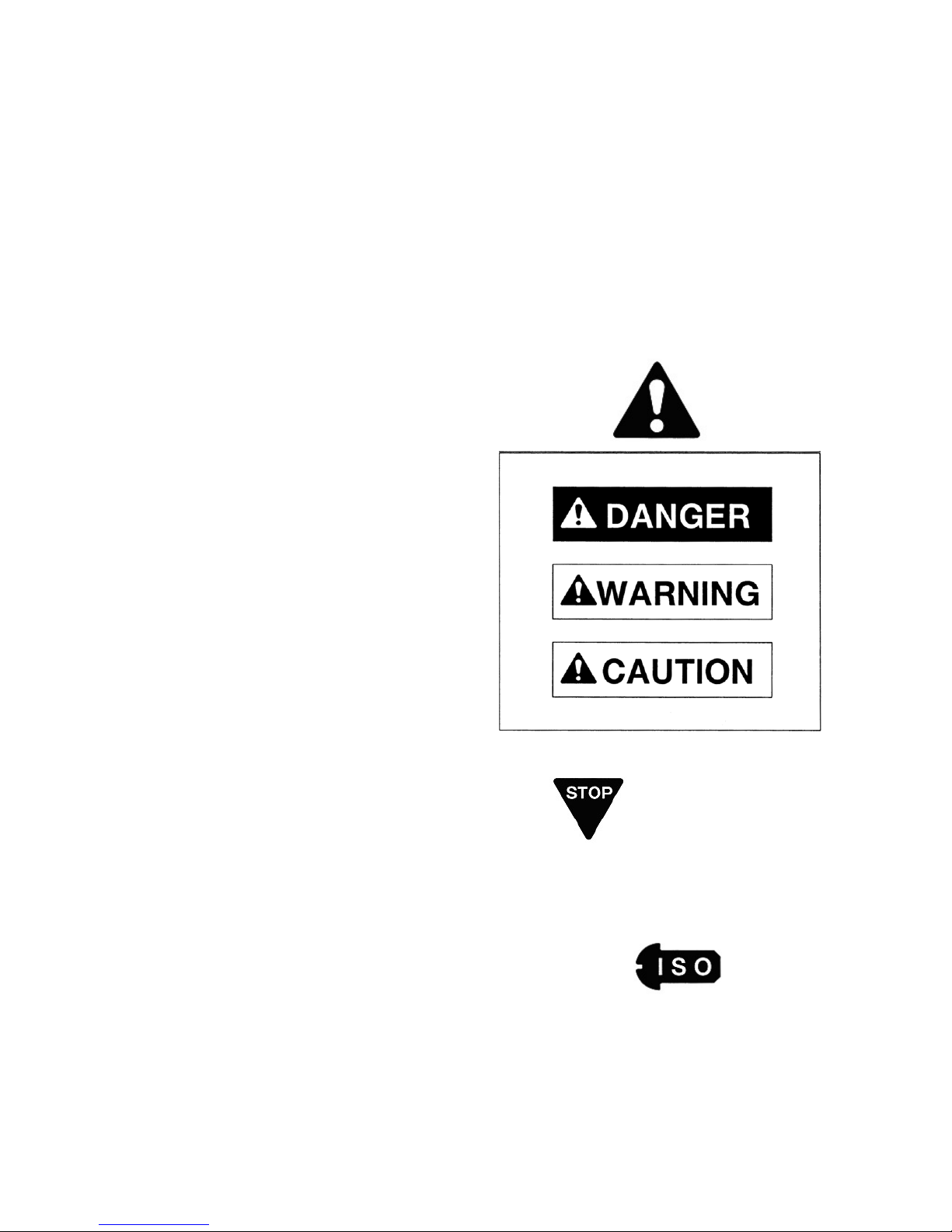
1. Safety-alert Symbol
This is the safety-alert symbol. When you see
this symbol on your tractor or in this manual, be
alert to the possibility of personal injury and
carefully read the messages that follow.
2. Signal Words
The signal words "DANGER" "WARNING"
"CAUTION" are used with the safety-alert symbol.
(1) "DANGER" indicates an imminently hazardous
situation which, if not avoided, will result in death
or serious injury.
(2) "WARNING" indicates a potentially hazardous
situation which, if not avoided, could result in
death or serious injury.
(3) "CAUTION" indicates a potentially hazardous
situation which, if not avoided, could result in
minor or moderate injury.
3. Service instructions
(1) This stop symbol indicates important proper
operation or service messages in this manual.
When you see this symbol, carefully read the
messages that follow.
IMPORTANT
(2) “NOTE” describes precautions to take while
working.
NOTE
4. Measurements
This tractor is of metric design. All hardware are
therefore metric (ISO). Make sure to use the
specified metric hardware when service becomes
necessary.
5. Direction
Right-hand and Left-hand sides of the tractor are
determined by facing in the direction of the tractor
forward travel.
Page 4

EF494T OM
TABLE OF CONTENTS
SAFETY INSTRUCTIONS 1
AFTER SALES SERVICE AND WARRANTY 15
After sales service 15
Availability of spare parts 15
PART NAMES 19
SAFETY LABEL LOCATION 21
FUNCTION OF EACH CONTROL 22
Engine 22
Traveling, PTO related functions 23
Hydraulic system 26
Others 29
PRE-OPERATION CHECKS 30
1. Pre-operation checks 30
2. Breaking in the engine (first 50 hours) 34
3. Starting and stopping engine 34
4. Raising or lowering implement 36
5. Adjusting lowering speed for implement 36
6. Starting and stopping 37
7. Traveling on the load 38
8. Traveling on the slope 39
9. Power steering 39
10. Driving in and out of Fields 40
11. Setting an adequate speed 40
12. Turning in a field 41
13. Position control 41
14. Using differential lock 41
15. Loading and unloading 42
16. Adjusting wheel tread 42
17. Hydraulic output 44
18. Using 3-point link 45
19. Adjusting top link 46
20. Mounting general farm implements 47
21. Notes on using service implement 48
22. Using PTO shift lever 49
23. Using drawbar hitch 49
24. Safety frame (ROPS) 50
AFTER OPERATION 51
1. After operation 51
2. Opening the bonnet and side covers 51
3. Checking and supplying fuel 52
4. Care for long period of storage 53
PERIODIC INSPECTION AND ADJUSTMENT 54
1. Check intervals 55
2. Oil and grease 56
3. Oil and water volume 56
4. Replacing oil 56
5. Replacing oil filter elements 58
6. Engine coolant 59
7. Fuel line 60
8. Replacing radiator screen and air cleaner elements 61
9. Checking battery 62
10. Checking fluid lines 63
11. Checking electrical wiring 63
12. Greasing 64
13. Adjusting brake 67
14. Adjusting clutch 68
Page 5

EF494T OM
15. Adjusting steering wheel 68
16. Adjusting fan belt 69
17. Adjusting tow-in 69
18. Replacing fuse 70
19. Checking tires 71
20. Color of exhaust gas 71
TROUBLESHOOTING 72
1. Engine parts 72
2. Clutch, brake and related parts 73
3. Hydraulic system 73
4. Electric system 73
SPECIFICATIONS 74
IMPLEMENT CAPACITIES 75
Page 6

EF494T OM
1
SAFETY INSTRUCTIONS
DANGER
Read these instructions carefully.
Important instructions are given for the safe operation
and servicing of the tractor.
Failure to follow these instructions is likely to result in an
accident involving death or serious injury.
STUDY THE TRACTOR AND IMPLEMENTS
Do not permit anyone unfamiliar with the tractor or the
operations of its implements to use the machine.
The operator’s manual should be considered a
permanent part of the tractor and should remain with the
tractor.
Know the positions and functions of all controls and the
meaning of any identification symbols on your controls,
gauges, and indicators before attempting to operate the
tractor.
Know how to stop the engine in an emergency.
Make sure you understand the capabilities, operating
characteristics and limitations of the tractor and
implement, such as maximum ballast weight, hydraulic
lifting capacity, speed, turning radius, operating
clearances etc.
Do not add extra ballast weight to compensate for a load
that is too heavy.
Page 7
EF494T OM
2
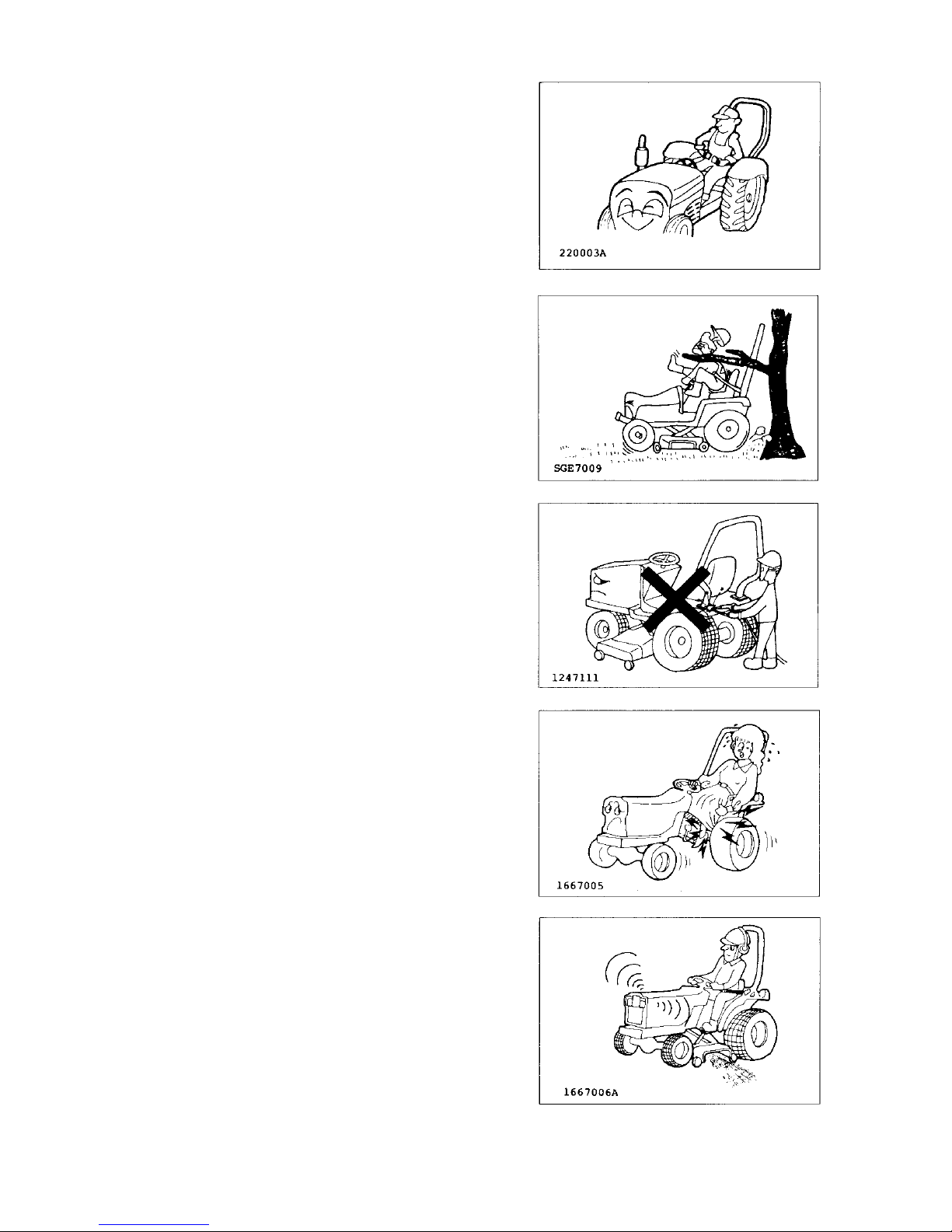
PROTECT OPERATOR SAFELY
Install an approved Roll-over Protective Structure
(ROPS) for safe operation. If a tractor rolls over without
a ROPS, death or serious injury is likely.
Always fasten the seat belt while operating the tractor
with Roll-over Protective Structure (ROPS) up.
Do not use the seat belt if the foldable Roll-over
Protective Structure (ROPS) is in the folded position or
the tractor does not have the Roll-over Protective
Structure (ROPS).
Extreme caution is required when operating a tractor
around trees or other overhead obstructions, such as
guy wires or power lines. Interference between the
ROPS and these obstructions may cause the tractor to
tip backwards.
Do not modify any structural portions of the ROPS by
welding, bending, grinding or cutting them. If any
component of the ROPS is damaged or involved in a
rollover incident, replace it with a complete new cage.
Do not attempt to repair the original one. Damaged or
modified structural parts impair the strength of the
ROPS and may lead to injury.
Avoid loose fitting or baggy clothing, torn clothing,
bulging pockets, frayed edges or heavy cuffs. Loose
frayed and bulky clothing can easily become entangled
in rotating parts. Wear work clothes and work shoes or
boots. Also you may need a: SAFETY HELMET,
SAFETY SHOES, EYE PROTECTION, HEAVY DUTY
GLOVES, HEARING PROTECTION, REFLECTIVE
CLOTHING, OR A RESPIRATOR/FILTER MASK.
Wear whatever safety gear and clothing is necessary for
the job.
Prolonged exposure to loud noise can cause impairment
or permanent loss of hearing. Wear a suitable hearing
protective device such as ear protectors or earplugs to
protect against objectionable or uncomfortable noise.
Page 8
EF494T OM
3
BEFORE OPERATING
Do not operate the tractor when tired, sick, sleepy,
drunk, feeling overworked, taking medicine, pregnant,
suffering from mental disease or if other improper
conditions are present. These conditions impair a
person’s skill and judgment. When you begin feeling
tired while operating the tractor, take a 10-minute break
to stretch, walk about, lie down or snack. Do not
continue if you still feel tired after taking a break.
Remove oil, grease or mud from the hand rails, steps,
pedals, controls, and floor to avoid slips or loss of
control.
In winter, scrape off any ice or snow on the handrails,
steps, pedals, controls, and floor .
To attach or remove an implement, refer to the
implement and tractor manufacturer’s manuals for the
proper procedures.
To unhitch an implement, move to a level area, lower the
implement to the ground and then block the equipment
in position before unhitching. If an implement has
wheels, block them to prevent it from rolling.
Make sure
(1) The tractor and implements are in good condition
and properly adjusted.
(2) To check for loosened bolts, adequate lubricants,
damaged or under-inflated tires, safety shields and
devices, steering and braking linkages, hydraulic
leaks, etc. Refer to this manual for more detailed
information.
(3) That implements are properly attached and hooked
up. Check that the PTO U-joint yoke and locking
devices are securely latched on their shafts.
(4) That the tractor’s PTO speed matches the
implement’s specifications.
Page 9
EF494T OM
4
STARTING
START THE ENGINE SAFELY
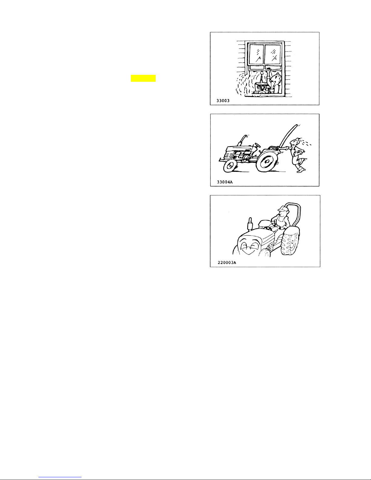
If you operate the engine inside a closed building, be
sure there is plenty of ventilation before starting the
engine. Exhaust fumes are poisonous. Carbon
monoxide is especially dangerous because it is odorless
and colorless. You can easily be overcome without
realizing it.
Always stay near the tractor and keep the parking brake
set securely while warming it up.
Only start the engine from the operator’s seat. Never
start the engine while standing on the ground.
Before you start the engine:
(1) Sit in the operator’s seat and adjust the seat position
if necessary.
(2) Make sure the ROPS is in working condition and
seat belt securely fastened.
(3) Lower any implement to the ground.
(4) Place speed shift lever and the PTO switch in
neutral.
(5) Set the parking brake.
(6) Disengage the PTO for the neutral position.
(7) Check all the instruments, gauges and indicator
lights.
(8) Be sure everyone is clear of the tractor and
implement.
Page 10
EF494T OM
5
DURING OPERATION
OPERATE THE TRACTOR SAFELY
Keep people and pets a safe distance away when
starting and operating the tractor and implement.
Do not permit any person other than the operator to ride
or board the tractor or implements, including any
wagons.
Do not play games with the tractor.
Never allow children to ride on your lap.
Do not touch the muffler, radiator, engine or other high
temperature parts before they have cooled down
completely.
Do not try to get on or off a moving tractor or
implements. Always use the handrails and steps and
face the tractor when getting on and off.
Never use control levers as a handhold and never step
on foot controls when getting on and off.
Do not get on the tractor with wet or greasy hands, or
muddy shoes. Do not jump off the tractor. Be aware of
slippery conditions on the ground.
Make sure you check the connecting points on your
equipment.
Keep hands, feet and clothing away from power-driven
parts. Keep others away from articulated joints, hitches,
drawbar, lift arms, PTO drives, cylinders, and anything
else that moves.
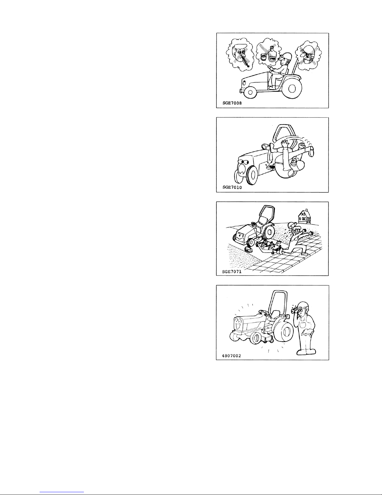
Never stand, or allow anyone else to stand, between the
tractor and an implement, unless the engine is turned off
and the parking brake is engaged securely.
Page 11
EF494T OM
6
OPERATE THE TRACTOR SAFELY (continued)
Oversized implements are dangerous for tractor
operation and are not safe for you. Refer to the
implement’s operator manual for the minimum and
maximum horsepower requirements and weights that
are allowed.
When using a heavy implement in front, always install
ballast or an implement on the rear for safe, stable
steering control.
When using a heavy implement on a rear 3-point hitch,
always install ballast or an implement on the front for
safe, stable steering control.
Slow the tractor down when crossing rough ground, tall
grass or weeds. Rocks, holes and stumps may be
hidden in the brush.
Do not let your tractor bounce. Y ou may lose steering
control.
Never use the tractor to round up farm animals.
Do not allow the tractor to coast downhill with the clutch
in, or with the gear shift in neutral.
When operating the tractor on a slope, set the wheel
tread as wide as possible for maximum stability, reduce
the engine speed and avoid quick application of the
brakes or sharp turns.
Stay off hills and slopes which are too steep.
Page 12
EF494T OM
7
AVOID TIPPING OVER
When starting the tractor on an uphill slope, shift to as
low a gear as possible and reduce the engine speed to
avoid tipping over backward.
Do not drive near the edge of a gully or a steep
embankment. Avoid holes, ditches, etc. which may
cause the tractor to tip over, especially on hillsides or
steep slopes.
When operating on slopes or rough uneven ground, it is
important to have as much distance as possible
between the wheels. Operate the tractor carefully at the
lowest speed.
Do not pull carts etc. from the top link or the top link
hinge, rear axle, or any point above the drawbar. Doing
so could cause the tractor to tip over backward. Only
attach items to be pulled to the drawbar.
Use care when pulling loads or installing a heavy
implement.
(1) Only use approved hitch points.
(2) Limit loads to those which you can control safely.
(3) Limit travel speeds so that you can control the tractor
safely.
(4) Do not turn too quickly.
(5) Use care when backing up.
(6) Install the amount of ballast recommended in the
operator’s manual.
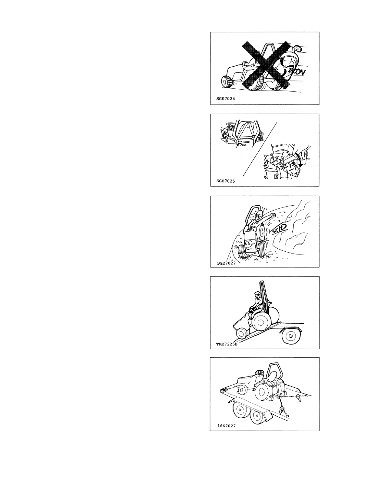
Driving forward out of ditch or in muddy conditions, or up
a steep slope, could cause the tractor to tip over
backward. If the mud is deep enough it will keep the
wheels from turning. Then, the tractor will rotate up and
back around the axle very quickly. When stuck in muddy
conditions, do not remove the implement or ballast
weight. Always back out.
Page 13
EF494T OM
8
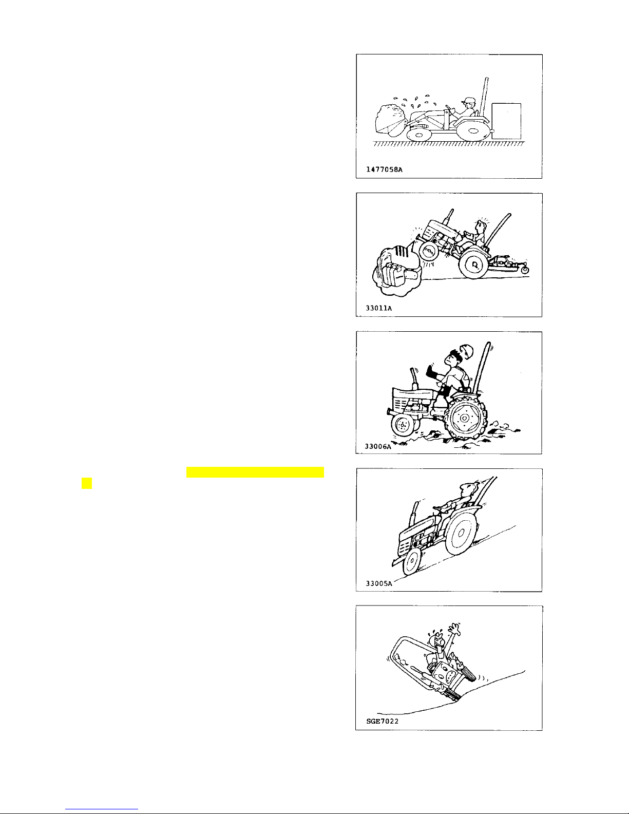
STAY CLEAR OF THE PTO
The PTO shaft safety guard (A) should be installed when
the PTO system is not in use.
Make sure that the tractor PTO speed matches the
implement’s required PTO speed.
Do not drive or operate the implement beyond the
tractor’s PTO speed.
Stop the engine and be sure the PTO has stopped
moving before:
(1) Connecting or disconnecting the PTO shaft.
(2) Making any adjustment to the PTO drive or 3-point
hitch.
(3) Adjusting, cleaning or servicing PTO driven
implements.
Page 14
EF494T OM
9
TRANSPORTING
Raise all implements and place them in the locked-fortransport position.
Do not drive the tractor on the road with implements in
motion.
Couple the brake pedals together for travel at road
speeds. (This only applies to models with two brake
pedals.)
Do not make sharp turns at road speeds.
Always dim your headlights when another vehicle is
coming toward you. Keep the lights adjusted so that they
will not blind the driver of another vehicle.
Before going down a steep hill, shift to the lowest speed
in order to control tractor with the least braking possible.
Do not coast downhill.
Do not stop or start suddenly when going uphill or
downhill.
When loading (or unloading) the tractor onto a vehicle,
use care as follows:
(1) Use a strong loading ramp or loading dock.
(2) Use the lowest reverse speed and drive up the
loading ramp backward.
(3) Set the parking brake and place wheel blocks firmly
under the vehicle’s wheels.
(4) Do not try to drive onto a trailer from the bank of a
ditch.
Secure the tractor and any other load with chains. Be
sure they are tight.
If chains are not available, use rope, wire, blocks, or a
winch cable. Check the load after traveling a few
kilometers, and every 100 km thereafter, to make sure
that the ties are not coming loose. Also, check after
rough bumps in the road.
Page 15
EF494T OM
10
TOWING
When towing a load that weighs more than the tractor,
the trailer should have its own brakes. When towing,
drive slowly, avoid hills and apply the brakes gently.
A safety chain will help control an implement being
pulled if it accidentally separates from the drawbar while
traveling. Using appropriate adapter parts, attach the
chain to the tractor drawbar support or to some other
specified anchor location. Leave only enough slack in
the chain to permit turning.
Do not tow the tractor faster than the tractor’s maximum
travel speed in the highest gear, and never more than 25
km/h (16 mph).
Check local regulations concerning towing. Towing is
illegal in some countries.
AFTER THE DAY’S OPERATION
PARK THE TRACTOR SAFELY
Park tractor on a firm level surface.
When parking the tractor, couple the brake pedals
together and set the parking brake securely. When you
must park on a slope, position the tractor at a right angle
to the slope and set the parking brake securely. Then,
block both the front and rear wheels.
Take all possible precautions as follows when leaving
tractor unattended:
(1) Disengage the PTO and lower any implement to the
ground.
(2) Move all shift levers to neutral.
(3) Couple the brake pedals together and set the parking
brake lever.
(4) Run the engine for 2 to 3 minutes at one-third throttle
speed and no load in order to cool it.
(5) Stop the engine and remove the key.
(6) Cycle the hydraulic controls to eliminate any residual
pressure.
Page 16
EF494T OM
11
MAINTENANCE AND SERVICE
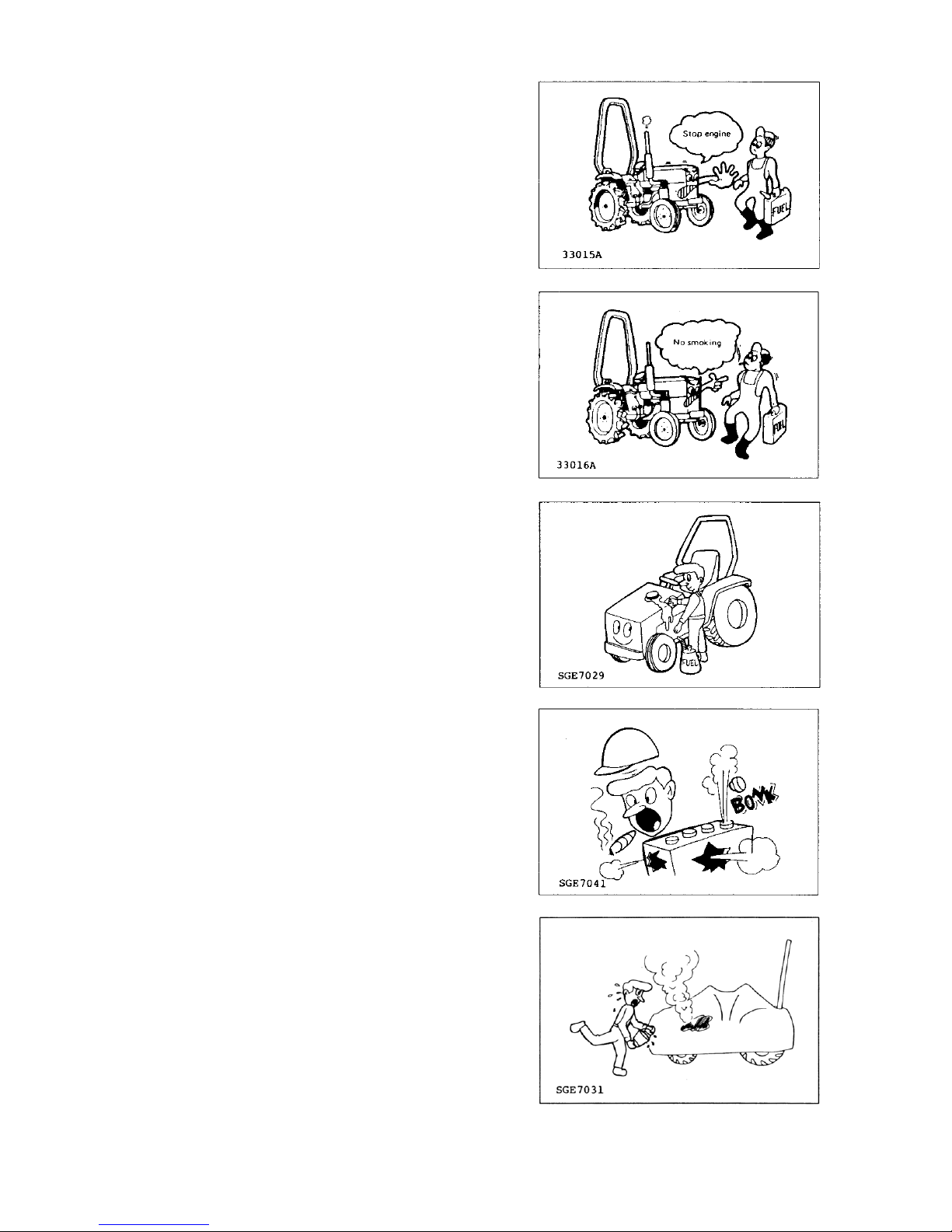
AVOID EXPLOSIONS OR FIRES
Refuel the tractor when the engine is cool and in a wellventilated area, preferably outside.
Never fill the fuel tank with the engine running.
Be sure to use the correct type and grade of fuel.
Keep all sparks, flames and smoking materials well
away while handling fuel.
Ground the fuel funnel or nozzle against the filler neck
on the tractor to prevent sparks.
Do not overfill the tank or spill the fuel. If fuel is spilled,
wipe it up immediately. Install the fuel tank cap securely
after refueling.
Be sure there is plenty of ventilation before charging the
battery. Gas produced while charging the battery is
explosive.
Keep all sparks, flames, and smoking materials well
away from battery. Hydrogen gas at a concentration as
low as 7 per cent can explode in the presence of a spark
or open flame and spatter acid.
Use a flashlight to check the battery electrolyte level.
Never use an open flame or match to check.
Keep the engine clean and free of grass, leaves, or
excessive grease.
Let the engine cool down before storing the tractor in an
enclosure or covering it with a sheet.
Page 17
EF494T OM
12
MAINTENANCE AND SERVICE (continued)
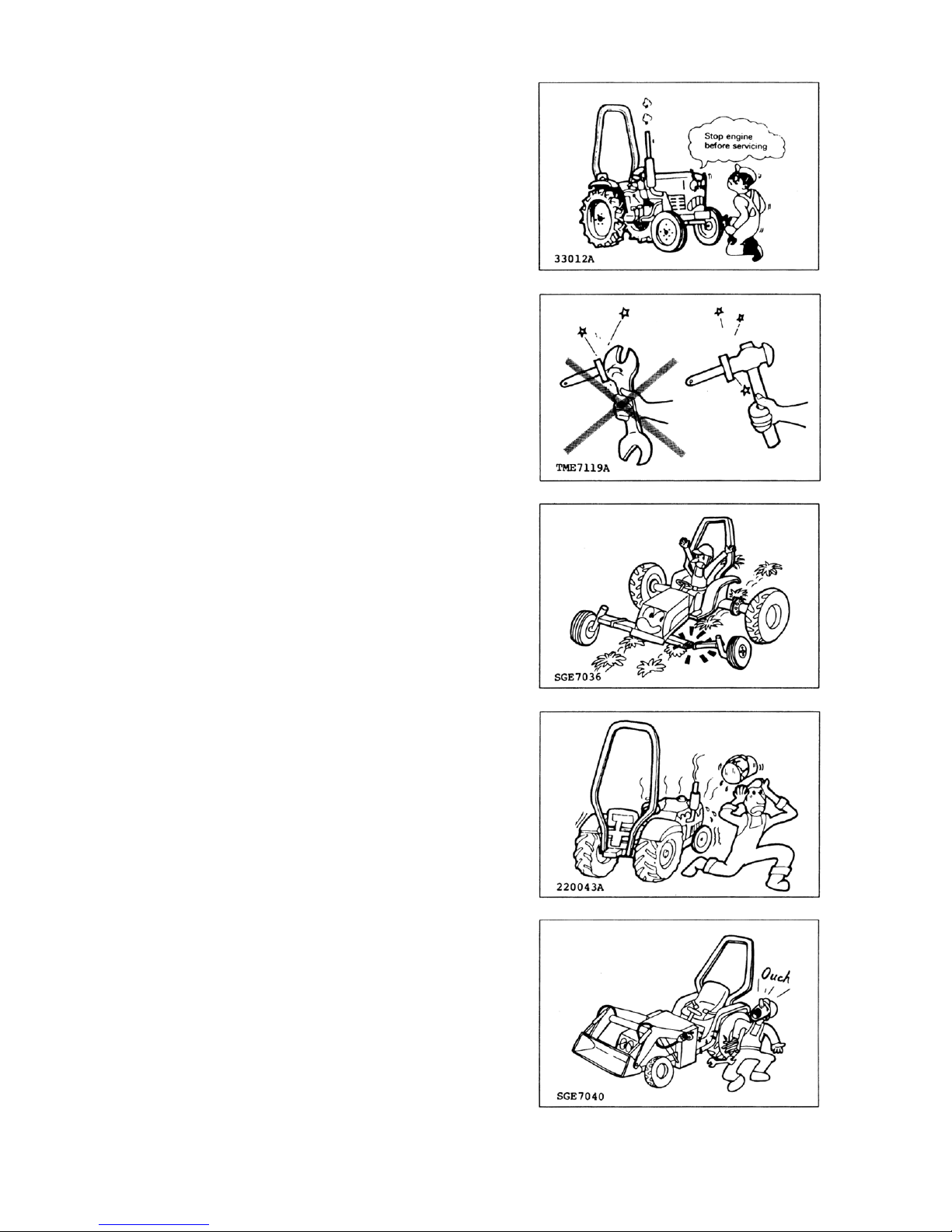
Do not service the tractor while it is in motion or while
the engine is running.
Before servicing the tractor, always set the parking
brake, block the wheels, lower the implement, release all
hydraulic pressure and place all the controls in neutral.
Use only the correct tools and equipment.
Unauthorized modification to the tractor may impair its
function, create an unsafe situation and reduce the
tractor’s useful working life.
Do not use substitute parts that may not meet the
strength and design requirements or may not fit the
tractor.
Do not use repair parts not approved by YANMAR.
Remove the radiator cap only when the coolant
temperature is low. Wait at least one hour after
operation, to allow the coolant to cool down.
Cover the radiator cap with a cloth before opening it and
release the pressure gradually before completely
removing the cap.
Do not service the hydraulic system when the hydraulic
oil is hot.
Do not set the relief valve pressure higher than stated in
the tractor or implement specifications.
Do not close off the overflow or bypass lines.
Page 18
EF494T OM
13
MAINTENANCE AND SERVICE (continued)
Hydraulic oil or diesel fuel escaping under pressure can
penetrate the skin and cause serious injury. Before
disconnecting any lines, be sure to relieve all pressure.
Before applying pressure, be sure all connections are
tight and all components are in good condition.
Fluid escaping under pressure from a very small hole
can be almost invisible. Wear safety goggles for eye
protection and use a piece of cardboard to check for
suspected leaks. Do not use your hands. If injured by
escaping fluid, see a doctor at once. Serious infections
and other problems can develop if proper medical
treatment is not administered immediately.
Disconnect the battery ground cable before working on
the electrical system or working in any area where you
might come into contact with electrical components.
Disconnect the ground cable first and reconnect it last.
The sulfuric acid in a battery is poisonous. It can destroy
clothing and burn the skin. Wear eye protection and
rubber gloves when filling the battery. If you spill acid on
yourself, flush your skin with water and apply baking
soda or lime to neutralize the acid. Then seek medical
attention right away. If acid is swallowed, get medical
attention immediately!
Page 19
EF494T OM
14
Storage
Whenever the tractor will not be used for a few months,
do the following:
(1) Drain the fuel tank.
(2) Lower any implement still attached.
(3) Set the parking brake and block the wheels.
(4) Remove the battery and store it in a cool, dry place,
out of the reach of children.
CAUTION
ALWAYS BE ENVIRONMENTALLY RESPONSIBLE
Follow the guidelines of the governmental agency for
the proper disposal of hazardous materials such as
engine oil, diesel fuel, engine coolant and, machine
fluid, grease.
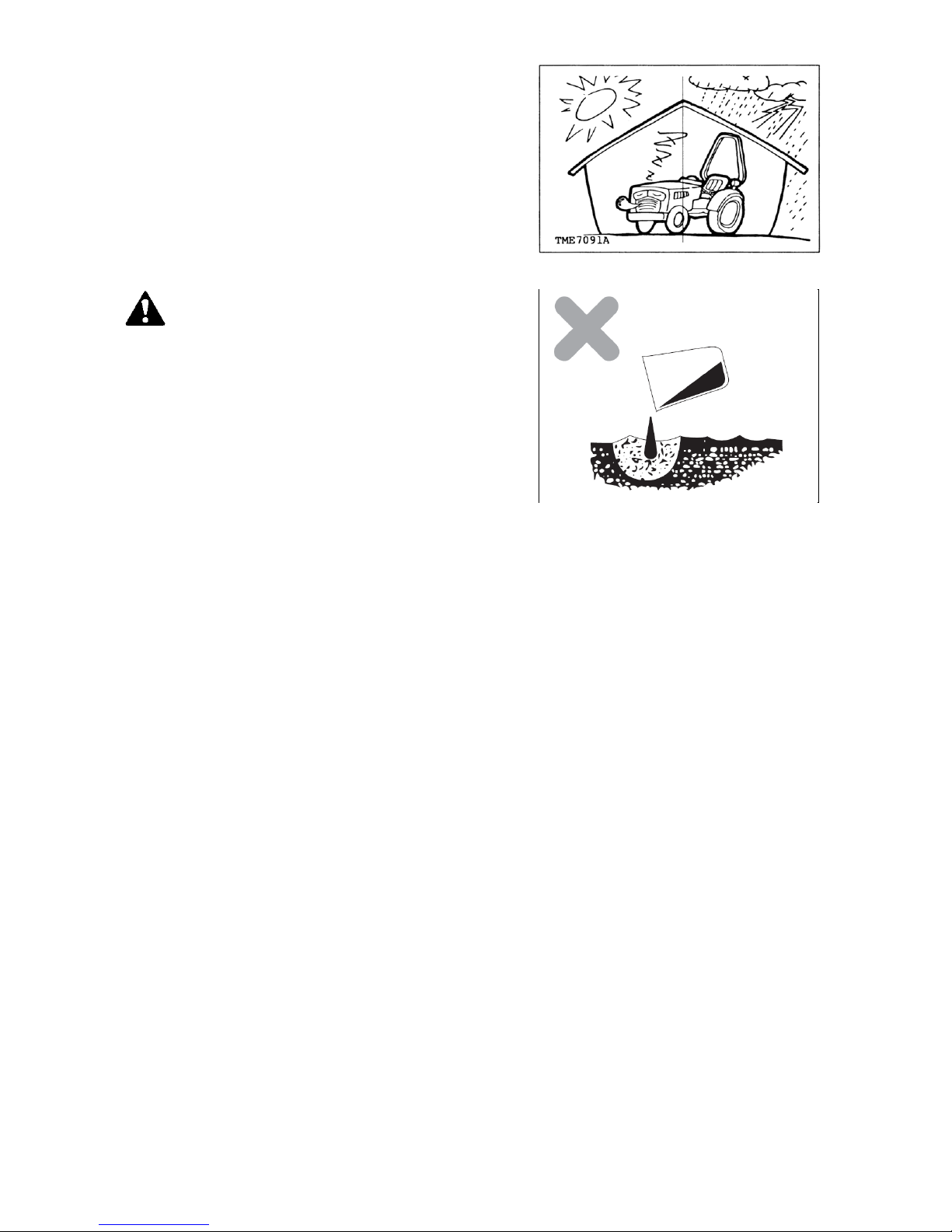
NEVER dispose of hazardous materials
irresponsibly by dumping them into a sewer, on the
ground, or into groundwater or waterways.
Failure to follow these procedures may seriously
harm the environment.
Comply with legal regulations and guidelines for
disposal of: empty containers for fuel, cooling water
(coolant), oil, grease; fuel/oil filters; batteries;
machine itself; machine accessories; and packaging
materials.
Page 20
EF494T OM
15
AFTER SALES SERVICE AND WARRANTY
After sales service
If your tractor is not working normally, refer to the
troubleshooting section in this manual. You can also
consult with your service representative.
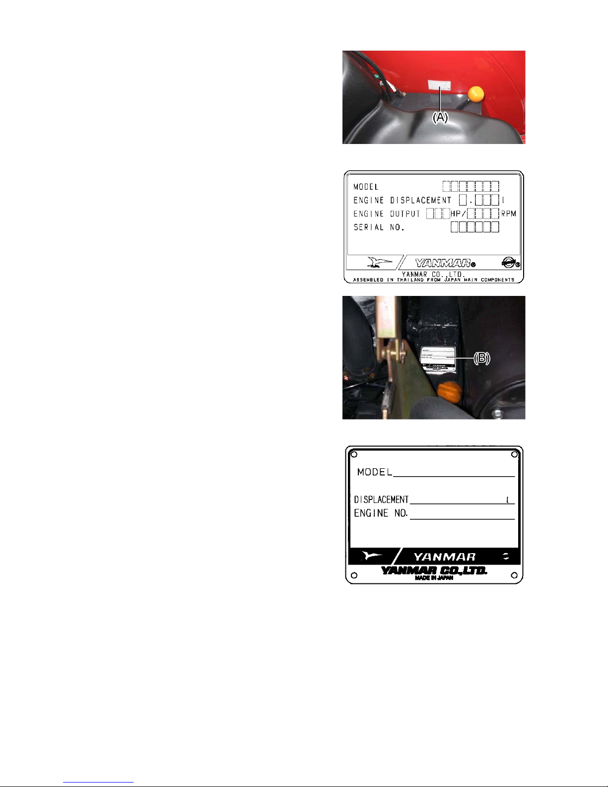
Information needed when asking for service:
Model name and serial number (A) of your tractor.
Engine type number (B)
Operating conditions. What type of work was being
performed when the problem occurred?
How long have you used your tractor? (total hours of
operation)
Any other information about the problem that has
occurred.
Availability of spare parts
Maintenance parts and spare parts will be available for
10 years after the production of this tractor series has
been discontinued. However, special parts will be
available subject to consultation. Yanmar may be able to
supply a particular part after the normal supply period.
(A) Tractor serial number
(B) Engine type number
(A)
(B)
PURPOSE OF THIS MACHINE
This machine is designed to be operated with a various
implement for particular tasks and for pulling a trailer in
a variety of agricultural operations. Other use or
modification is prohibited.
Orientation and Position Marks
A right-hand and Left-hand side of the machine is
determined by facing in the direction of the machine
forward travel.
Page 21
EF494T OM
16
FUSE BOX
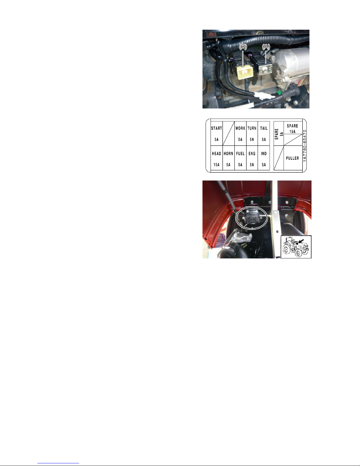
(1) The alternator fuse (60A) and main fuse (60A) are of
slow blow type. When any of these has been blown,
contact your local YANMAR dealer.
(A) Main fuse: 60A
(B) Alternator fuse: 60A
(2) The electrical fuses are in the engine compartment.
Use of fuse other than a correctly rated one way may
cause damage to the electrical system.
Replace the blow fuse with a new fuse of the same
amperage rating.
START : Starter motor 5A
WORK : Working light 5A
TURN : Turn signal light 5A
TAIL : Tail light 5A
HEAD : Head light 15A
HORN : Horn 5A
FUEL : Fuel pump 5A
ENG : Timer relay 5A
IND : Indicator light 5A
Page 22
EF494T OM
17
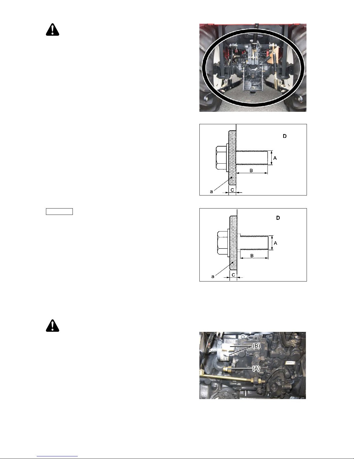
WARNING
You must carefully note the length of the bolts when you
install Yanmar recommended implements and
equipment behind the transmission case.
1. First, it is necessary to measure the thickness of the
parts. Then use bolts whose length includes the
extra measured thickness.
2. When the original part is removed and a different
part is installed, it is necessary to measure
difference in thickness of the two parts and change
the length of the bolts appropriately.
If you don’t use appropriate consideration of these
issues, you will damage the transmission case and
create a dangerous situation.
Aluminum cases
Reference
The bolt length “B” in the case must be 2.0 times the
diameter of “A”.
For casting metal cases, rear axles, etc.,
The bolt length “B” in the case must be 1.5 times the
diameter “A”.
D: Transmission case
Cast metal cases
When you install part “a” behind the
transmission case, use bolts whose length
includes measurement “C”.
CAUTION
Do not try to adjust engine speed adjuster screw (A)
located on engine fuel injection pump. Any accident
or failure resulting from adjusting the screw would
not be covered by Yanmar's guarantee.
Do not try to unseal and adjust engine fuel injection
pump (B). Any accident or failure resulting from
adjusting the pump would not be covered by
Yanmar's guarantee.
Page 23
EF494T OM
18
WARNING
Do not move the tractor if the wheel mounting bolts
or nuts are loose. If the tractor is driven with loose
nuts or bolts, there is a possibility that an accident
will occur.
Make daily and periodic wheel inspections to check
for loose nuts and bolts on the wheels. If they are
loose, retighten them to the specified torque.
IMPORTANT
The first 50 hours of handling and maintenance greatly
affect the service life and performance of a new tractor.
In particular, pay spe cial attention to the following points
during this period of time.
(1) Refrain from sudden acceleration and sudden
braking.
(2) Do not increase the speed too much or carry any
more load than is necessary.
(3) Operate the tractor only after the engine has warmed
up sufficiently.
(4) Slow down on a rough road or on a slope.
(5) Check the tightness of the wheel mounting bolts after
the first 10 hours and again after the first 50 hours. If
they are loose, retighten them. (For specific
tightening torques, refer to the table in the instruction
manual.)
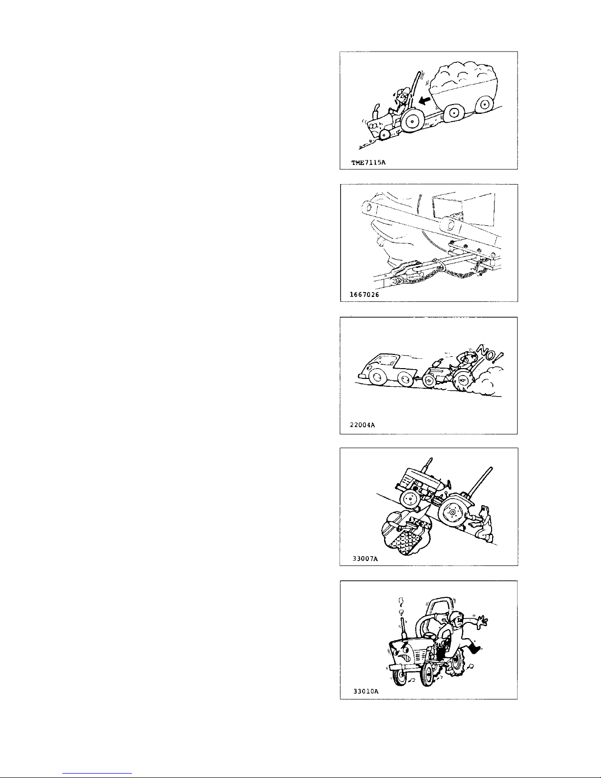
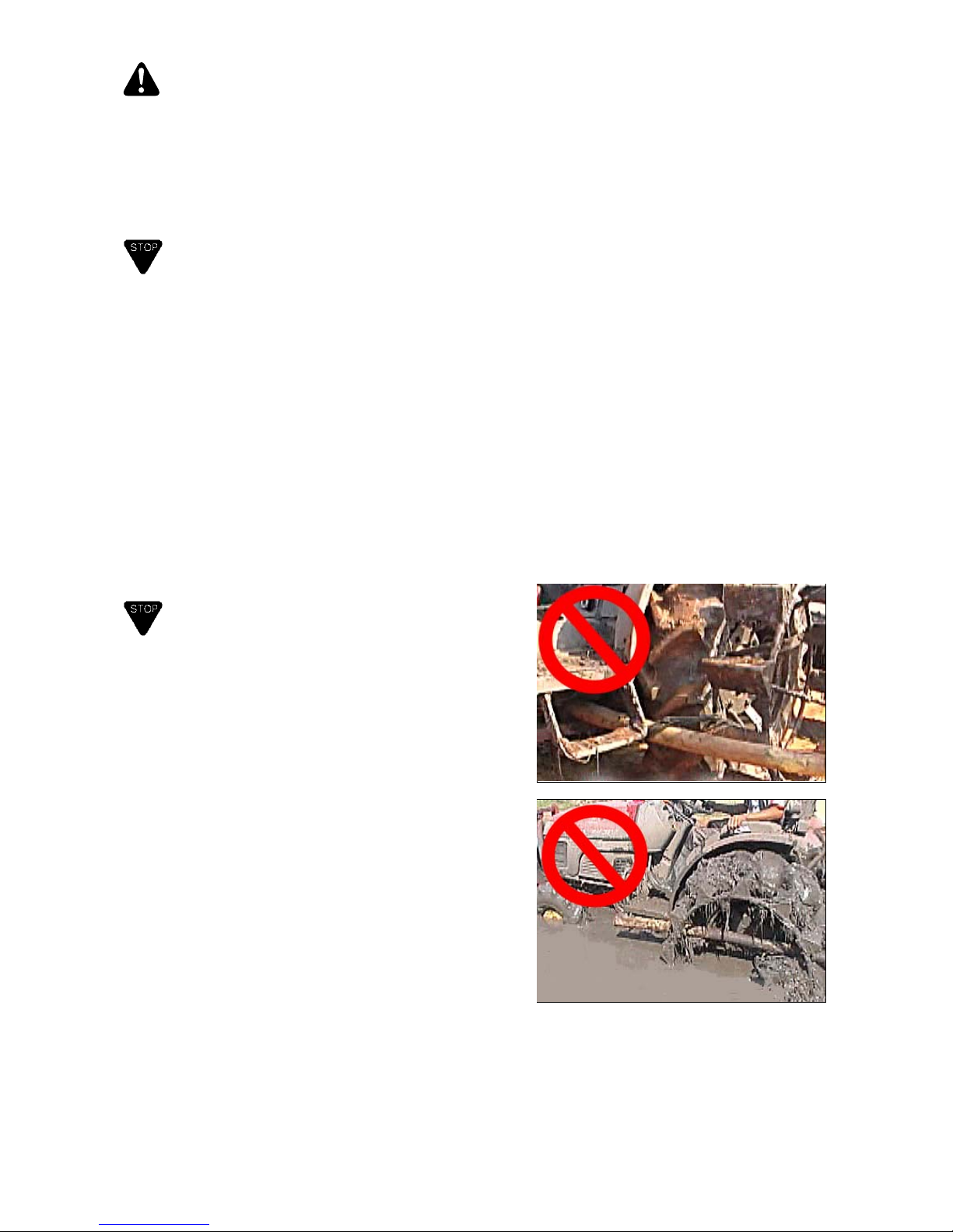
IMPORTANT
When the tractor gets stuck in a muddy portion in field,
do not tie a piece of lumber, log or pipe to the front or
rear wheels to drive out of the muddy portion.
It may break transmission and/or rear axle inner parts or
cases.
Put a ladder bridge under the wheels and then drive out.
Or use strong rope or chain to pull it out of the muddy
portion slowly by the other tractor or so.
Note:
These photos show rear tire with cage
wheel.
Page 24
EF494T OM
19
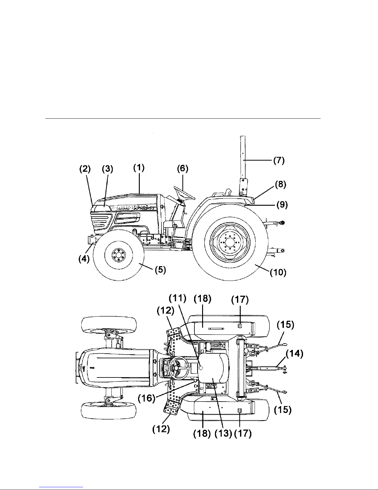
PART NAMES
(1) Bonnet
(2) Headlights
(3) Side lens
(4) Front axle bracket
(5) Front wheels
(6) Steering wheel
(7) Safety frame (ROPS)
(8) Tail lamp
(9) Fuel tank
(10) Rear wheel
(11) Hydraulic stop-slow return valve
(12) Sub step
(13) Operator’s seat
(14) Top link
(15) Lower link
(16) PTO shift lever
(17) Flasher lamp (Side marker lamps)
(18) Rear fender
Page 25
EF494T OM
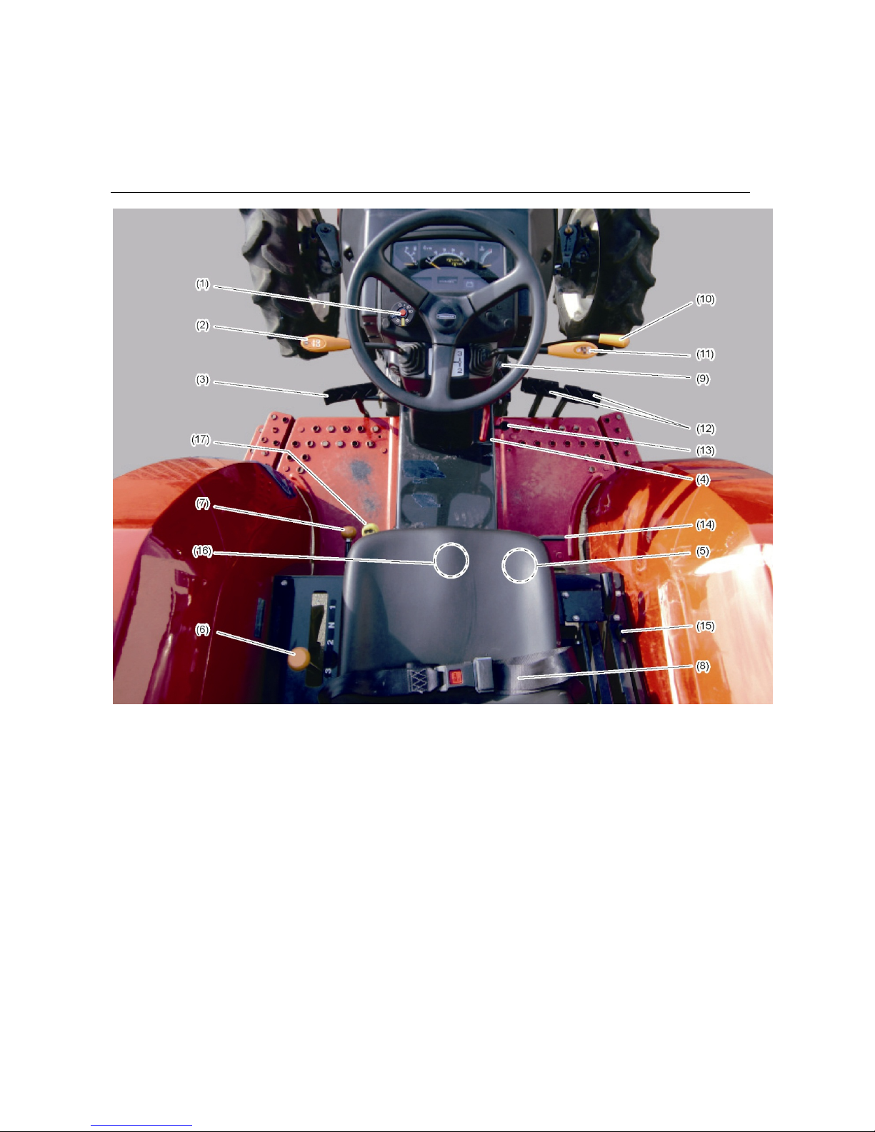
20
(1) Light switch, Horn switch, Flasher switch
(2) Reverser lever
(3) Clutch pedal
(4) Parking brake lever
(5) Operator's seat adjusting pin
(6) Range shift lever
(7) Front wheel drive lever
(8) Seat belt
(9) Main switch
(10)
A
ccelerator lever
(11) Main shift lever
(12) Brake pedal
(13) Accelerator pedal
(14) Differential lock pedal
(15) Position control lever
(16) Hydraulic stop slow return valve
(17) PTO shift lever
Page 26

EF494T OM
21
SAFETY LABEL LOCATION
(A) ROPS right side frame
(1) 1A7874-65360
Label, brake coupling
(2) 1A8310-65310
Label, caution
(3) 1A8310-65340
Label, fire caution
(4) 198163-65350
Label, danger rotate shaft
(5) 198283-65651
Label, Thailand only
(6)
Label, tractor ID
(7)
Label, engine ID
(8) 1A7781-65560
Label, speed
(9) 1A6150-93151
Label, caution cover
(10) 198163-65930
Label, caution muffler
(11) 198163-65940
Label, safety cover
(12)
Label, ROPS ID
(13) 198263-65950
Label, seat belt
(14) 1A8310-65300
Label, warning escape
Page 27

EF494T OM
22
FUNCTION OF EACH CONTROL
Engine
Main switch
Used to turn on and off the engine
WARNING
When the tractor is not in use, never fail to remove the
key and store it at a safe location. Do not allow a child to
access the key.
(A) ST AR T
(B) ON
(C) OFF
START:
Starter motor runs to start the engine.
Release the key when the engine starts,
and the key returns to the "ON" position
automatically.
ON:
The electric current is on. If the engine is
stopped, the engine lubricating oil lamp and
charge pilot lamp turn on.
OFF:
The electric current is shut off. The key can
be removed.
Accelerator lever
(A) Accelerator lever
(B) Engine slow speed
(C) Engine high speed
The accelerator lever is used to increase or decrease
the engine speed. Used to keep the engine at a constant
speed.
Accelerator pedal
(A) Accelerator pedal
(B) Depress the pedal to increase the engine
speed.
(C) Release the pedal to decrease the engine
speed.
The accelerator pedal is used to increase or decrease
the engine speed, mainly during travel on the road. To
increase the engine speed, depress the pedal.
Page 28

EF494T OM
23
Traveling, PTO related functions
Main shift lever
(A) Main shift lever :1, 2, 3, N
This lever changes the transmission system in 3 stages.
Combination with the range shift and reverser creates 9
forward speeds and 9 reverse speeds. Operate the main
shift lever while depressing the clutch pedal.
Reverser lever
(A) Reverser lever
(B) F: Forward
(C) N: Neutral
(D) R: Reverse
This lever is used to change running direction of tractor.
Move the lever forward for running forward and move
the lever rearward for running reverse.
Lift up the lever and move it to desired position.
When shifting the lever, be sure to depress clutch pedal
and that tractor stops completely.
CAUTION
When shifting between forward and reverse, depress
clutch pedal and brake pedal to stop the tractor
completely and put the lever to desired direction.
Range shift lever
(A) Range shift lever: 1, N, 2, 3
This lever changes the transmission system in 3 ranges.
Combination with the main shift and reverser makes 9
forward and 9 reverse speeds.
When operating the range shift lever, be sure to depress
the clutch pedal and that tractor stops completely.
Page 29

EF494T OM
24
PTO SHIFT LEVER
CAUTION
Strictly maintain the PTO speed as specified by the
implement. Otherwise, the implement can be damaged,
leading to an accident.
(A) PTO shift lever
The PTO shaft (power takeout shaft) changes its speed
in 2 stages. To change the speed, depress the clutch
pedal all the way.
Brake pedal
DANGER
For traveling on road, link the both pedals with the
connector. One sided braking can cause the tractor to
make an abrupt turn or topple.
(A) Connector link for traveling on road
(B) Left Brake
(C) Right Brake
Left and right pedals can be operated separately. For a
sharp turn in the field, depress the brake in which
direction you want to turn. The rear tire on that side will
lose drive, providing a sharp turn. For traveling on road,
never fail to link both pedals with the connector.
Parking brake lever
(A) Parking brake lever
(B) Brake pedal
To efficient braking, link the left and right brake pedals
with the connector.
Depress the pedals all the way and pull the parking
brake lever upward.
To release the brake, push down the parking brake lever
and depress the parking brake pedal.
Page 30

EF494T OM
25
Clutch pedal
(A) Clutch pedal
To disengage the clutch function, quickly depress the
pedal. To engage, slowly release the pedal. Do not keep
your foot on the clutch pedal unless necessary.
Otherwise, the lifetime of the clutch may be reduced.
Differential lock pedal
WARNING
Never fail to turn off the differential lock to make a turn.
Otherwise, you cannot make an intended turn and an
accident may result.
(A) Differential lock pedal
(B) Release lock
(C) Press to activate differential lock
This pedal makes both side wheels to turn as a
consolidated form if one of rear wheels idles. This
arrangement is useful to avoid slippage in muddy
conditions.
Depressing the pedal automatically causes a differential
lock condition. Releasing the pedal unlocks the
differential system.
2WD/4WD lever
(A) Front wheel drive lever
(B) ON: Four-wheel drive
(C) OFF: Two-wheel drive
This lever is used to switch between two and four-wheel
drive.
Page 31

EF494T OM
26
Hydraulic system
Position control lever
(A) Position control lever
(B) Raise
(C) Lower
(D) Stopper
This lever fixes an implement in a definite position.
The stopper is used to limit the working range of the
position control lever. To adjust the stopper position,
loosen the knob.
Upper stopper stowage
Set the knob in the uppermost position.
(A) Upper
(B) Upper stopper
(C) Position control lever
(D) Knob
Adjusting the stopper
Move the knob to a required position.
Preventing an implement from dropping
Set the lever as illustrated.
Hydraulic stop and slow return valve
Hydraulic stop, Slow return valve
(A) Hydraulic stop, slow return valve
(B) Fast lowering of implement
(C) Slow lowering of implement
Fully clockwise turn stops hydraulic pressure.
Slow return function adjusts the lowering speed of an
implement. Fully clockwise turn stops hydraulic pressure
to the implement.
Page 32

EF494T OM
27
ELECTRIC SYSTEM
Turn signal switch
Turn signal functions when key switch turns on.
Turn the turn signal switch anticlockwise to blink right
side turn signal lamp and turn clockwise to blink left side
lamp.
(A) Turn signal switch
(R) Right lamp blinks.
(L) Left lamp blinks.
Head light switch
Headlights turn on when key switch turns on.
Turn head light switch clockwise to turn on head light s.
(B) Light switch
(OFF) Headlights turn off.
(LB) Headlights turn on with low beam.
(HB) Headlights turn on with high beam.
CAUTION
When there is an oncoming vehicle in night time, be
sure to switch to low beam position. If keep on high
beam, it may cause traffic accident.
Horn button
Horn functions when key switch turns on.
Push horn button to blow horn.
(C) Horn button
Page 33

EF494T OM
28
INSTRUMENT PANEL
(A) Tachometer
Fuel gauge
(A) Red region
Indicates the remaining fuel level. Prepare to replenish fuel if the
pointer comes in the red area.
Water temperature
(A) Red region
Indicates the temperature of the cooling water in operation. If the
pointer comes in the red region, stop the work and check for
abnormality.
Engine lubricating oil lamp
This lamp lights when the main switch is turned on and goes off
when the engine starts. If the lamp lights during engine speed,
suspect an abnormality in the lubrication circuit.
Stop the engine immediately and locate the trouble.
Charge lamp
The charge lamp goes off when the engine increases its speed
above 1500 rpm and the battery starts to be charged. Note that
charging will not take place at an engine speed below 1000 rpm.
Hour meter
Indicates the operating hour of the tractor. Multiply the figure in
white frame by 6 to indicate the operating time in minutes.
Page 34

EF494T OM
29
Others
Driver's seat adjustment pin
The driver's seat should be adjusted to suit your physical
shape.
(A) Seat adjust lever
(B) Release
(C) Lock
Seat belt
WARNING
Always fasten seat belt while operating the tractor
with the ROPS.
Do not use the seat belt if the tractor does not have
the Roll-over Protective Structure (ROPS).
(A) Buckle
(B) Tongue
Connect both segments of the belt with the buckle,
being careful to avoid twisting of the belt, adjust the belt
length, being suitable for the operator.
To unfasten, press the release button (marked PRESS)
in the buckle.
Page 35

EF494T OM
30
PRE-OPERATION CHECKS
1. Pre-operation checks
DANGER
Never lubricate or supply fuel oil while the engine is
warm.
Never smoke during fuel replenishing.
Never use bare lamp/light during fuel replenishing.
Do not crawl or step under a service machine.
After replenishing fuel, be sure to fasten the fuel tank
cap and clean off the fuel spill. A fire can result.
WARNING
To check or service your machine, fix it on the flat ground,
out of traffic of other vehicles or people. Otherwise, the
tractor can collapse and cause an unexpected accident.
When accessing beneath an implement, close the
hydraulic valve completely to stop the oil flow. Otherwise
the implement may abruptly fall by any reason, causing
injuries to the people within the reach.
CAUTION
Never fail to stop the engine before checks or
maintenance. Otherwise, you may be trapped in the
machine and seriously injured.
To check or service the machine, wait until the
engine and mufflers are cooled down. You may be
burnt.
Never fail to remount the covers and parts detached
for service. Otherwise, you may be trapped in the
machine and seriously injured.
Page 36

EF494T OM
31
For safety reasons, always check the tractor before
initiating day's works. Remove any abnormalities.
CHECK THE FOLLOWINGS IN ORDER:
(1) Abnormalities in previous day.
(2) Walk around the tractor to look into:
Deformed parts, damages, wear.
Air pressure of tires, wear of tires.
Wear of various parts, loosened bolts and nuts.
Loosened bolts and nuts of the tire rims and disks.
Fuel oil amount and leak, damage on the fuel piping
.
(3) Check inside the bonnet.
Oil level, quality of oil, leak.
Quantity of cooling water, damage in hoses.
Color of the hydrometer or level of battery liquid,
depending on battery type.
Page 37

EF494T OM
32
Clogging or dirt in air filter.
Tension or damage of cooling fan belt.
Check the radiator grill and engine room for dust.
Check electrical wiring for wear of sheath and loose
joints.
(4) Sitting on the operator’s seat.
Effect and play in the brake.
(A) Play 30-40mm
Page 38

EF494T OM
33
Play in the steering wheel.
(A): Play 20-50mm
Effect and play in the clutch pedal.
(A): Play 15-25mm
(5) Start the engine:
Check for abnormal sound.
Color of exhaust gas.
(A) What color?
Function of lamps and meters.
Page 39

EF494T OM
34
2. Breaking in the engine (first 50
hours)
The new tractor should be operated carefully for the first
50 hours. This will have a large positive effect on the
lifetime and performance of the tractor throughout its
life. Pay particular attention to the following points:
(1) Refrain from abrupt starts and stops.
(2) Do not use a speed higher than necessary and do
not load the machine more than necessary.
(3) Begin operation only after the engine has warmed
up sufficiently.
(4) Slow down on rough roads or slopes.
(5) Check the tractor thoroughly after breaking it in for
the first 50 hours.
3. Starting and stopping engine
WARNING
Before starting the engine, sit in the driver's seat
and make sure the levers and controls are within
the reach for safe operation. Negligence will
cause a serious injury.
Do not start the engine in a closed room. Start the
engine outdoor where the good ventilation is
available. If you are forced to start the engine in a
confined room, make sure the ventilation is
proper. Gas oxidation can lead to death.
WARNING
Before and after operation, never fail to check and
service the machine. Particular check will be
required at the clutch, brake pedals and controls,
and steering devices. Negligence can cause a
serious injury to the operator and/or damage to
the machine.
Engage the parking brake during the warm-up
operation. Otherwise the tractor may abruptly start
to run.
NOTE:
In cold season, pay a special attention to the warm-up
for adequate operation of the hydraulic system.
Temperature Warm-up operation
0 ~ -10°C more than 10 min
-10 ~ -20°C more than 20 min
< -20°C more than 30 min
Page 40

EF494T OM
35
Starting
CAUTION
Do not start the engine if the position control lever is not
in the LOW position. The implement may abruptly raise
causing a damage or injury to the human and machine.
(1) Set the fuel filter and water separator to "O" to open
the fuel cock.
(A) Fuel cock open
(B) Fuel cock close
(2) Put the main and range shift levers, reverse lever
and PTO shift lever in the N position.
(3) Set the position control lever in LOW.
(4) Put the accelerator lever in the TOP position. Fully
depress the clutch pedal and turn the main switch to
START.
(5) After the engine has started, immediately release the
main switch.
IMPORTANT
* The engine cannot be started without putting both the
main and PTO shift levers in the N position.
Page 41

EF494T OM
36
(6) Warm up the engine by running under no-load at
1500 rpm for 5 minutes approximately.
(A) 1500 rpm
NOTE:
The starter motor consumes plenty of current from
the battery. Do not keep it running for more than 10
seconds. If it fails to start the engine, allow one
minute before retry. Then, execute steps (6) - (7).
Never turn the main switch to START if the engine
has been started or is running.
Stopping
(1)
Reduce engine R.P.M. with the accelerator lever.
(2) Turn the main switch to OFF.
IMPORTANT
Stopping a hot engine suddenly can damage the engine
because of overheating. Keep engine running unloaded
at 1200 - 1500 RPM for about 2 minutes, to prevent
damage.
4. Raising or lowering implement
Adjust the position control lever back and forth to raise
or lower the implement.
(A) Position control lever
(B) Lower
(C) Raise
5.
Adjusting lowering speed for
implement
WARNING
Never crawl beneath or step in the implement. Severe
injury may result.
To reduce the lowering speed for an implement, turn the
hydraulic stop slow return valve clockwise.
To increase the speed, turn the valve counterclockwise.
Turning the valve fully clockwise will stop the oil
pressure and stop lowering the implement no more.
(A) Fast descending speed
(B) Slow descending speed
NOTE:
Do not operate the position control lever when the
hydraulic slow return valve is closed. Hydraulic parts
may be damaged.
Page 42

EF494T OM
37
6. Starting and stopping
WARNING
Make a slow start after calling attention of the people
in the vicinity. Do not make an abrupt start. Human
injury can result.
For traveling, never fail to link the left and right brake
pedals with the connector.
When you leave the tractor, park it on the safe flat
location; never fail to put on the parking brake, put
the reverse lever and range shift lever in N (neutral);
and lay down the implement on the ground. Block
the wheels. Otherwise, the tractor may move without
intention of the operator, causing a serious accident.
CAUTION
Never keep your foot on the clutch pedal while traveling
or working. Otherwise, an accident may result.
NOTE:
Operate the main shift lever and the range shift lever or
reverse lever after the machine stops completely.
Starting
(1) Check that the left and right brake pedals are tied
together with the connector.
(2) Set the engine speed around 1500 rpm with the
accelerator lever.
(3) Move the position control lever to Upward to lift the
implement to a maximum height.
(4) Depress the clutch pedal and place the main and
range shift levers in the wanted position.
(5) Put the reverse lever in the position of F or R.
(6) Slowly release the clutch pedal. The tractor starts to
run.
Stopping and parking
(1) Return the accelerator lever to LOW to slow down
the speed.
(2) Depress the clutch and brake pedals to stop the
tractor, and set the main shift lever in position N.
(3) Put the main shift lever, reverse lever and PTO shift
lever in N (neutral).
(4) Make sure the left and right brake pedals are
connected with the connector. Depress the brake
pedal and put on the parking brake.
(5) Lay down the implement, if any, on the ground by
putting the position control lever in LOW.
(A) Position control lever
(6) Turn the main switch to OFF to stop the engine.
Page 43

EF494T OM
38
7. Traveling on the load
WARNING
To travel on the road or cross a farm ridge, never fail
to link the left and right brake pedals. One-sided
braking effect will roll over the tractor or result in a
sharp turn.
Follow the traffic regulations and rules when running
on the road. Wear the helmet.
Do not carry other persons except a driver.
CAUTION
Remove implements are better when traveling on
the road, or an accident may result.
Put the PTO shift lever in N and link the right and left
pedals together.
For traveling on the road or to lock the hydraulic
device in the upper position, adjust the upper
stopper and move the position control lever to the
stopper.
(A) Position control lever
(B) Upper stopper
Adjust the traveling speed with the foot accelerator
pedal.
To change the traveling course, notify others by
flasher switch.
Watch any following cars on the rear view mirror and
give way to them.
On narrow farm paths, tilled ground or roads with
weedy shoulders, travel at a reduced speed noting
the road shoulders.
When passing other cars at night, switch the
headlight to the low beam for the convenience of
others to pass by.
(A) Low beam
(B) Flasher switch
NOTE:
When traveling, keep open the hydraulic stop slow
return valve and put the position control lever in the
RAISE position, and the set the stopper.
Page 44

EF494T OM
39
8. Traveling on the slope
WARNING
Do not change speeds on the slope. Travel slowly
on the slope. Use the engine brake on down-slope.
Do not travel on the slope with the reverser lever,
the main shift lever or the range shift lever set in the
N position.
Do not depress the clutch on the slope; it causes a
great danger as the tractor may glide down.
To start on an up-slope, use a low gearshift and set
off at low speed. Abrupt start will jump up the front
wheel.
Before leaving the tractor, stop the engine, set the
parking brake and block the wheels.
Shift should be changed after reaching a highest
point on the slope. To stop on the slope, lock the
parking brake lever.
9. Power steering
CAUTION
The steering wheel is easily rotated when the tractor is
running.
Pay a special attention in operating the steering wheel
when traveling on the road. Power steering is effective
only while the engine is running. The steering wheel will
be slightly heavier at a low engine speed.
IMPORTANT
Turning hard the steering wheel will cause the relief
valve to sound a blowing sound. Do not operate the
tractor with this sound continuously for an extended
period. It damages the hydraulic components.
Do not operate the steering wheel while the tractor is
stationary except for an unavoidable case.
Otherwise the tires or rims are damaged.
Page 45

EF494T OM
40
10. Driving in and out of Fields
WARNING
Always connect the left and right brake pedals with
the connector. Otherwise, one-sided braking can
cause a roll over.
When approaching the field or when crossing a
ditch, use a gangplank of sufficient strength to enter
the field. Lower any implement to reduce the center
of gravity.
Climb a slope backwards, in reverse. Drive down a
slope forward, in low gear.
Before starting to climb a hill, lower any implement.
After the rear wheels are on the ridge (A), you can
lift the implement.
(A) Ridge
11. Setting an adequate speed
9 forward speeds and 9 reverse speeds are available by
the combination of main, range and reverse shift levers.
Use an adequate speed for works referring to the table
below.
(A) Main shift lever
(B) Range shift lever
(C) Reverse shift lever
Driving Speed
F/R
Shift
position
Main shift Range shift
km/h
Forward
1 1 1
1.63
2 2 1
2.26
3 3
1
3.30
4 1
2
4.00
5 2
2
5.57
6 3
2
8.14
7 1
3
14.18
8 2
3
19.72
9 3
3
28.80
Reverse
1 1 1
1.68
2 2 1
2.33
3 3
1
3.41
4 1
2
4.13
5 2
2
5.74
6 3
2
8.39
7 1
3
14.62
8 2
3
20.33
9 3
3
29.70
Page 46

EF494T OM
41
12. Turning in a field
WARNING
Disconnect the differential lock before turning.
Otherwise, an intended turn will not be possible and an
accident may result.
Refer to the relevant section for operating the differential
lock.
Reduce the engine speed and make a slow and smooth
turn. To enable a quick turn in the field, remove the
connector linking the left and right brake pedals; upon
turning the steering wheel, depress the brake pedal in
the direction to which you want to turn.
Lift up the implement and turn.
13. Position control
The position control maintains an implement in a wanted
height.
(1) Set the implement in an adequate height with
the position control lever.
(A) Position control lever
(B) Stopper
(2) To set the lower limit of the implement, adjust
the position control lever until it stops in a wanted
position. Fix it with the lowest stopper.
14. Using differential lock
WARNING
Disengage the differential lock before making a turn.
Otherwise, intended turn is not possible and an
accident will result.
Do not use differential lock while traveling on the
road. Otherwise, stable drive is not assured,
incurring an accident.
Depressing the differential lock pedal locks the
differential gearing and causes both side wheels to turn
at the same speed. Releasing your toot from the pedal
will automatically bring back the differential system.
Lock the differential system when running or leaving a
muddy path. It is also useful when the tractor fails to
travel along a linear course.
(A) Differential lock pedal
IMPORTANT
Set the differential lock after reducing the engine
speed.
If difficult to unlock the differential system, try to
depress the clutch pedal or lightly depress the brake
pedal.
Page 47

EF494T OM
42
15. Loading and unloading
DANGER
While loading or unloading tractor to or from the truck,
never try to change the course on the gangplank. Use
the slowest speed. Do not use the clutch. Otherwise,
loss of control can result in injury or damage to the
tractor.
WARNING
Park the truck on the flat ground where less traffic is
expected. Stop the engine and lock the parking
brake. Block the wheels of the truck. Use the
gangplank of sufficient strength. Fix or tie the
gangplank on the truck.
Reverse shift for loading, forward shift for unloading
Fasten the tractor firmly with the rope. If the tractor
falls off the truck, it may be damaged or injure
someone.
(1) Prepare the gangplank of sufficient strength.
(2) Never fail to link the two brake pedals with the
connector.
(3) Put the shift in the LOW position and load the tractor
onto the truck with a reverse shift.
(4) Should engine failure occur, descend down the
gangplank. Restart the engine and climb the
gangplank.
16. Adjusting wheel tread
Adjust the tractor wheel tread according to the type of
crops and widths of planting rows.
Apply a wide wheel tread for works on slopes or for a
traction work.
Consult your service outlet for the adjustment of the
wheel tread.
Page 48

EF494T OM
43
DANGER
Do not drive the tractor if the wheel mounting bolts
or nuts are loose. If the tractor is driven with loose
nuts or bolts, there is a possibility that an accident
will occur.
Make daily and periodic wheel inspections to check
for loose nuts and bolts on the wheels. If they are
loose, retighten them to the specified torque.
When wheel tread width was changed, check the
bolts and nut tightening after the first 10 hours and
again after the 50 hours. If the bolts are loose,
retighten them. After that, check every 100 hours
operation.
Fastening torque (Front and rear)
Fixing bolts for wheel and axle shaft:
186 N-m (19 kgf-m)
FRONT TIRE: 8-18
REAR TIRE: 13.6-26
Page 49

EF494T OM
44
17. Hydraulic output
CAUTION
Never fail to stop the engine before trying to detach the
hydraulic plug or pipes. Otherwise, you may be injured
by high pressure oil.
Single action cylinder (e.g. dump trailer)
(1) Set the position control lever about 20 mm below the
top position.
(A) Position control lever
(B) About 20 mm
(2) Fasten the hydraulic stop slow-return valve fully
clockwise.
(A) Hydraulic stop slow-return valve
(B) Close
(3) Remove the hydraulic output plug, and connect the
high pressure hose of an implement.
* Keep removed copper packing and plugs.
(A) Hydraulic output plug
NOTE:
3-point rear hitch implement cannot be controlled
by position control lever while stop slow-return
valve is closed.
Double action cylinder
(1) Remove the plug (A). Insert and tighten the screw
plug (B) to switch inner hydraulic oil flow.
(2) Remove plugs (D) on the right side of hydraulic
housing. Put the filter adapter (C) to the return port
(IN). Connect the hydraulic valve of implement.
Port at the front side: OUT (to take out)
Port at the rear side: IN (to return)
(A) Plug, 3/4-16UNF
(B) Screw plug, PTF 1/4-18 (198245-42160)
(C-1) Filter adapter, 3/4-16UNF (1A7780-45950)
(C-2) Gasket, 19x1.0 (23414-190000)
(D) Plug, 3/4-16UNF
NOTE:
Rear hitch implement can be controlled by position
control lever.
Keep plug (D) for future reuse.
Page 50

EF494T OM
45
18. Using 3-point link
(1) Mount the lower link on the lower link hinge and fix it
with a lock pin.
Left and right links are commonly usable, but note
the front and rear position. Mount the link so that the
link mounting hole comes backward.
(A) Lower link
(B) Lift link mounting holes
(2) Fix the check chain on the chain bracket and the
lower link mounting holes (rearmost). Foremost
holes are used for coupling the lift link.
(A) Check chain bracket
(B) Check chain
(3) Couple the lift link with the lift arm and the lower link.
(A) Lift link
(B) Lower link
(A) Lift link hole
(B) Lower link hole: Not possible to use
(C) Lower link hole: Standard
(D) Lower link hole
(E) Check chain
(F) Lower link separation
Page 51

EF494T OM
46
*Identify the left and right lift links. Mount the
adjustable one to the right and the fixed one to the
left.
(A) Left lift link (Fixed)
(B) Right lift link (Adjustable)
(4) Install the top link at the top link hinge hole.
Chose (A) or (B) or (C) depending on the implement.
19. Adjusting top link
Loosen the lock nut for the top link and turn the
turnbuckle to adjust the length of the top link. When an
implement is not used, hang the top link on the hook.
(A) Hook
(B) Lock nut
(C) Top link
IMPORTANT
Install the top link lock nut (B) on the implement side. If
the lock nut were to be mistakenly installed on the
opposite side, it will cause the top link to be damaged.
Page 52

EF494T OM
47
20. Mounting general farm implements
(1) Adjust the length of the right lift link to make the left
and right lower links equal in height.
(A) Lower link
(B) Lift link
(2) Align the center of the tractor with the center of the
implement on the flat ground.
(3) Fix the left lower link on the implement, then fix the
right lower link. If the right lower link pinhole is out of
position, turn the lift link to bring the hole in the
position.
(4) Fix the standard top link on the top link hinge using
the ball socket lock pin. Next, loosen the top link lock
nut and turn the turnbuckle. Lock the implement with
the lock pin.
(5) Loosen the lock nut of the top link and turn the
turnbuckle for adjustment. Fix the implement in the
top link mounting position with a pin.
(A) Top link
(B) Top link hinge
(C) Right lift link
(6) Lower the implement on the ground. Adjust its
posture with the top link turnbuckle.
(7) To install an implement requiring the drive force,
follow the instruction on the nameplate mounted on
the safety cover for the drive shaft.
(8) Lift the implement slightly and make sure it is level. If
not, adjust the right lift link.
(9) Lift the implement to a maximum height and rotate it
with a hand. If it is hard to rotate with a hand or if the
rotation is not smooth, adjust the length of the top
link.
Page 53

EF494T OM
48
(10) Check chains
Adjust check chains (A).
1) For use of implements such as a plough, harrow and
subsoil, adjust check chains (A) so that an
implement can move 5 - 6 cm to right and left.
Prevent an implement from swinging to hit against
the wheels and tires.
2) For use of implements such as a rotary tiller and
mower, adjust check chains (A) so that an
implement can move 1cm to right and left.
(11) Dismantling is done in the reverse order as the
fixing process.
IMPORTANT
Remove the drawbar if the drawbar interferes with an
implement.
Fasten lower links to prevent from swinging to hit
against wheels and tires when driving the tractor
without an implement.
21. Notes on using service implement
WARNING
When moving the tractor to mount an implement, never allow a
person or persons between the tractor and the implement.
Mount or dismantle an implement on a flat ground using a safe
method. Use the lighting during nighttime works.
When a heavy implement is mounted on the tractor, apply a
counterbalance to maintain a balanced condition.
Before leaving the tractor for mounting an implement, never fail
to engage the parking brake and stop the engine. Make sure the
PTO shift lever is in N.
For traction work, always use the draw bar. Do not attach to
other parts of the tractor.
Use a wider wheel span for a traction work or works on the
slope.
Do not operate the low speed machines at a higher speed than
the rated. Maintain the rated PTO speed.
When drawing a trailer, interlock the trailer brake with the tractor
brake. Do not change the shift on the slope.
Mounting an implement machine results in a considerable overall
length; be careful not to hit farmers or constructions in the
vicinity.
Negligence of safety precautions may cause serious injury
or death.
WARNING
Running the PTO speed below or above the rated operating speed of
the implement may cause damage to the tractor or the implement.
Page 54

EF494T OM
49
22. Using PTO shift lever
CAUTION
USE the specified PTO Speed. If not, the implement
can be damaged and cause an injury to people in
vicinity.
PTO speed can be changed in 2 stages to suit a
particular work. To change the shift, completely
disengage the PTO clutch by stepping on the PTO clutch
pedal. When the PTO is not used such as while running
on the road, set the PTO shift lever at N position.
(A) PTO shift lever
PTO speed
PTO shift PTO speed (rpm)
1 568
2 769
(Engine speed is : 2800rpm)
23. Using drawbar hitch
DANGER
Traction should always be done with the drawbar hitch.
Traction at the top link or rear axle causes the tractor to
roll over.
A stationary drawbar hitch is provided.
(A) Draw bar hitch
(B) Fixing pin
Combined PTO drive and traction
For a combined operation of PTO drive and traction, the
length from the edge of the PTO shaft to the mounting
position on the drawbar hitch implement is set to 356 mm.
CAUTION
Avoid injury!
Use only the drawbar that was provided with the
machine. Do not install or use a floating-type drawbar
or any other type drawbar.
If a longer drawbar hitch were installed, there is a
possibility that the attached section might be
damaged and the implement could become
disconnected.
Hitch towed loads only to the drawbar to avoid
rearward upset.
IMPORTANT
Avoid damage!
Maximum static vertical load on drawbar should not
exceed the maximum recommendations. Drive slowly
with heavy loads.
Strain is greatly increased by speed and rough
ground. Do not exceed maximum vertical load 374kg
on drawbar.
Page 55

EF494T OM
50
24. Safety frame (ROPS)
The safety frame is designed to protect the driver from an
accident. Never fail to use the safety frame when the
tractor is in use.
WARNING
Always fasten the seat belt while operating the tractor
with Roll-over Protective Structure up.
Do not use the seat belt if the foldable Roll-Over
Protective Structure (ROPS) is in the folded position or
the tractor does not have the ROPS.
Do not modify the safety frame. Safety factor can be
lost.
Damaged frame should be replaced as a complete set.
Partial repair may lead loss of safety level.
Folding in safety frame
(1) Loosen bolts (B) and remove bolts (A).
(2) Push down the frame backward.
(3) Install bolts (A) as the right figure shows and
tighten all bolts (A), (B).
(A) Bolt M16x100 2 pieces
(B) Bolt M16x100 2 pieces
Setting up the safety frame
(1) Loosen bolts (B) and remove bolts (A)
(2) Push up the frame.
(3) Install bolts (A) as the right upper figure shows
and tighten all bolts (A) and (B).
Bolt tightening torque:
167-206 N-m (17-21 kgf-m)
(A) 26156-161002 Bolt M16x100, plated 2 pcs.
(B) 26156-161002 Bolt M16x100, plated 2 pcs.
(C) 26356-160002 U-nut, M16 4 pcs.
(D) 22137-160000 Washer 16, polished 8 pcs.
Page 56

EF494T OM
51
AFTER OPERATION
1. After operation
DANGER
To cover the tractor for storage, allow at least 10
minutes of cooling time after the engine has been
stopped. Otherwise, a fire may start.
Wash the tractor with water, wipe off, and lubricate the
moving parts and sliding parts. Fill grease to the grease
nipples.
CAUTION
Never fail to stop the engine before stating checks
and maintenance. You may be pulled into the
machine and be injured.
Wait until the muffler and the engine get cool before
starting checks and maintenance.
NOTE:
Be careful not to spray water on electrical parts. Water
infiltration can cause a trouble in the electrical system.
2. Opening the bonnet and side covers
Opening/closing the bonnet
Opening
(1) Push down the bonnet lever (A) to release the
bonnet lock.
(2) Lift the bonnet and fix it with the stopper (B).
Closing
(1) Lift slightly up the bonnet to unlock the stopper
(B); mount the stopper (B) in the clip.
(2) Lower the bonnet and press it down until a click
is heard.
Page 57

EF494T OM
52
Removing/mounting the side covers
Removing
(1) Open the bonnet.
(2) Put the locking knobs in the vertical position
(each forward and rear).
(3) Remove the side covers.
Mounting
(1) Clamp the cover lower hooks (x 2).
(2) Fix the cover top with the locking knob.
3. Checking and supplying fuel
DANGER
Never smoke during re-fueling.
Never use a bare lamp/light during re-fueling.
After adding fuel, be sure to fasten the fuel cap and
clean off the fuel spill.
Never refuel while the engine is running or still hot
after stopping. A fire can result.
Set the main key switch to ON. If the fuel gauge reads in
the red region, open the fuel cap and add the fuel.
(A) Red region
(B) Fuel cap
Page 58

EF494T OM
53
4. Care for long period of storage
WARNING
For stowage over a long period of time, remove the
battery from the tractor and remove the main key.
Otherwise, an accident may occur.
CAUTION
Lock the clutch pedal for stowage over a long period of
time. Otherwise, an accident may occur.
If the tractor is not to be used over a lengthy period of
time, take the following maintenance:
(1) Place the tractor in a well ventilated place and
remove the weight or other attachments. Remove the
implement or lay it down on a wooden plate.
(A) Good ventilation
(2) Coat the exposed metallic parts with anti-rusting
oil, engine oil or grease.
(3) Fill the tank with fuel oil. Otherwise, moisture will
develop in the tank and cause rust. Put the fuel cock
in the CLOSE position.
(4) Fully charge the battery. It is recommended to
detach the battery from the tractor and keep it in a
dark cool place. If the battery is kept on the main
body, disconnect the ground line (negative lead).
(5) Remove the cooling water.
(6) Cover the opening of the air cleaner, muffler or
engine oil port with a polyethylene bag or the like to
prevent the moisture from getting in.
(7) To prevent the clutch from being rusted, fully
depress the clutch pedal and put on the clutch pedal
lock.
(8) Fill the front and rear tires with air to normal
pressure.
The periodic check and inspection during stowage over
a long period will ensure the preferable conditions of
your tractor.
NOTE:
The battery is subject to self-discharge. Fully charge it
up at least once a month.
Page 59

EF494T OM
54
PERIODIC INSPECTION AND ADJUSTMENT
WARNING
Check or maintenance should be done with the tractor
fixed on the flat ground, free from normal traffic. Pay
attention not to topple the tractor. Put blocks to the
wheels.
CAUTION
Do the periodic check and inspection every year.
Replace the fuel pipes and power steering hoses
every 2 years. Otherwise, an accident or machine
damage may result.
Never fail to stop the engine before commencing
checks and service.
Remount the covers which have been removed for
maintenance. The revolving parts may catch a
person nearby leading to a serious injury.
Periodic inspection and maintenance in off-season will
ensure the preferable conditions of your tractor. To keep
your machine working in good conditions, ask your
service shop for a regular inspection every year.
It is recommended to replace fuel pipes, rubber hoses,
and electrical wires every two years.
IMPORTANT
Only use the Yanmar genuine parts.
Otherwise, service accidents can result.
We recommend the use of the Yanmar lubricants
that are available from your local Yanmar dealer.
Page 60

EF494T OM
55
1. Check intervals
x: Checks required
CHECK ITEMS 50 h 100h 150h 200h 250h 300h 350h 400h 450h 500h 550h 600h
Engine lubrication oil Replace Replace Replace Replace Replace Replace Replace
Engine oil element
Replace
Replace
Replace
Transmission oil
Replace
x x x x
Replace
x x x x x
Replace
Line filter (Hydraulic)
Replace
Replace
Replace
Transmission oil strainer
Clean
Clean
Clean
Fuel filter
Replace
Replace
Water separator
Drain Drain Drain Clean Drain Drain Clean
Radiator interior Clean the interior of radiator when replacing cooling water
Cooling water Check before every work / Replacing every year
Front axle oil
Replace
x x x x
Replace
x x x x x
Replace
Air cleaner element
x x x x x
Replace
x x x x x
Replace
Radiator screen
x x x x x x x x x x x x
Clean cooling fan,
radiator
x x x x x x x x x x x x
Battery liquid level Check before every work
Battery liquid gravity
x x x x x x
Fuel piping, connections
x x x x x x x x x x x x
Rubber hoses
(Power steering)
x x x x x x x x x x x x
Radiator hoses Replace hoses every two years
Hydraulic rubber hoses Replace hoses every two years
Fuel pipe, electric wires Replace pipes and wires every two years
Electric wiring,
connections
x x x x x x x x x x x x
Greasing
x x x x x x x x x x x x
Greasing, propeller shaft
Apply
Fastening of steering
wheel fix nut
x x x x x x
Important nuts and bolts
x x x x x x x
Cooling fan belt
x x x x x x x
Engine breather pipe
x x x x x x x x x x x x
Engine crank case
x
Clearance of exhaust
valve
x
Fuel injection valve
x
Generator, start motor
x x x x
Hydraulic system
x x x x
Fixing bolts of tires
x x x x x x x
Break-in period is 50 hours. If not reached, take up 1 year instead.
Items marked "Replace" should be replaced every two years even before suggested time intervals.
Replace the power steering hoses every 2 years.
Page 61

EF494T OM
56
2. Oil and grease
OIL, GREASE TYPE
Fuel Diesel fuel only
Engine oil SAE 30 or 40 API Grade CD or better
Grease Multipurpose Grease
Transmission oil, Hydraulic
system oil
TF-500 Transmission fluid
* At temperature below – 10°C, use Super No.3 light oil.
3. Oil and water volume
(Unit: liters)
EF453T OIL TYPE
Fuel 40 Diesel light oil
Cooling Radiator 4 Anti-rusting fluid
water Sub-tank 0.45 Anti-rusting fluid
Engine oil 5.3 SAE 30 or 40
Transmission oil 27 TF-500A Transmission fluid
Front axle oil 7.5 TF-500A Transmission fluid, SAE 90
4. Replacing oil
DANGER
Never add oil while the engine is warm or running.
A fire may occur.
CAUTION
Never add oil just after stopping the engine. You may be
burned.
Engine oil
Check
Draw out the oil gauge on the right side of the engine and
wipe off oil with a cloth. Reinsert and remove it again to
see if the oil level is within the upper and lower marks.
If insufficient, add the new oil as much as the normal level
through the supply port.
(A) Oil gauge
(B) Oil supply port
NOTE:
Check the oil level before the engine starts or when the
engine is cool.
Replacing oil
Remove remaining oil through the drain plug on the lower
part of the engine. Add the new oil through the oil supply
port. Select a proper type of engine oil and replace it
periodically considering the temperature and operating
conditions.
(A) Drain plug
Page 62

EF494T OM
57
Transmission oil
Check
Draw out the oil gauge on the rear part of the transmission
and check the oil level. The level should be between the
upper and lower limits. If insufficient, add the new oil to the
normal level. Also check for leaks.
(A) Oil supply port
(B) Oil gauge
Replacing oil
Remove the remaining oil through the drain plugs on the
bottom of the transmission case. Removal is easy if the
transmission case is warm. Add the new oil through the
supply port on the rear part.
Transmission oil is commonly used with hydraulic oil
and power steering oil.
Use Yanmar transmission fluid TF-500 or equivalent for
transmission oil.
(A) Drain plug
Cleaning transmission oil strainer
When replacing transmission oil, wash the oil strainer with
diesel fuel.
(A) Oil strainer
Equivalent to TF-500A
SUPPLIER BRAND NAME
Mobil Mobil Fluid 425, 424
Castrol Agricastrol MP, CASTROL UTF
Shell Tellus Oil 32 or 37, Donax TD
Ford ESN-M-2C-134A
Esso Torque Fluid 56
John Deere J20B, J14A
BP Tractran UTH
Page 63

EF494T OM
58
Front axle oil
Check
Remove the oil gauge plug on the top of the front axle.
Wipe off the gauge rod and reinsert it without screwing.
Redraw it and see if the oil level is within the upper and
lower marks. If insufficient, add the new oil through the oil
supply port to the normal level. Check also for oil leak.
(A) Oil gauge plug
(B) Oil supply port
Replacing oil
Remove oil through center drain plug on the lower part of
the front axle and drain plugs on the bottom of the right and
left gear cases. Add oil through the right port.
Use Yanmar TF500A transmission fluid, or carrier red 80B,
or equivalent for front axle oil.
(A) Center drain plug
(B) Gear case drain plug
5. Replacing oil filter elements
Engine oil element
Replace the engine oil element at intervals of 300 hours or
every 2-3 times of replacing the engine oil.
(A) Turn left to detach
(B) Oil element
Replacing oil
(1) Remove engine oil and turn the cartridge anticlockwise
with a filter wrench.
(2) Apply a slight coating of oil on the rubber ring on the
bottom of the new cartridge. Mount the cartridge with a
filter wrench.
(3) After replacing the engine oil, run the engine until the
engine lubricating oil lamp goes off.
(4) When the engine lubricating oil lamp goes off, again
check the oil level with the gauge. If insufficient, add the
oil.
Page 64

EF494T OM
59
Line filter (Transmission oil element)
The line filter is of a cartridge type. Replace it with a new
one at intervals of 300 hours thence.
(A) Line filter
Replacement
(1) Remove the transmission oil and remove the cartridge
by turning it anticlockwise.
(2) Apply a slight coating of oil on the rubber ring on the
bottom of the new cartridge. Mount the cartridge
securely.
(3) After replacing the transmission oil, idle the engine and
check the oil level with an oil gauge. If insufficient, add
the oil.
6. Engine coolant
DANGER
Never open the radiator cap when the engine is hot. Hot
steam and boiled water may blow out and you may suffer
severe burns.
Check
Open the bonnet and check water level in the sub-tank
whether water is between “FULL” and “LOW” marks. If
water is insufficient, remove sub-tank cap and add clean
water.
Be sure to close the sub-tank cap firmly.
[A] Sub-tank
[B] Sub-tank cap
[C] Upper limit (FULL)
[D] Lower limit (LOW)
Replacing coolant
(1) Remove the coolant drain plug and drain cooling
water. It is easier for draining to open radiator cap.
(2) Clean the inside of radiator with tap water until dust
or rust does not come out.
It is suggested to use radiator detergent. Fill radiator
with water and detergent and run the engine in idle
speed for more than 15 minutes. Drain the water.
(3) Fill radiator with clean water.
It is recommended to mix anticorrosive. Run the
engine for about 5 minutes in idle speed to mix water
and anticorrosive.
IMPORTANT
The mixing ratio of anticorrosive varies depend on
manufacturer. Follow the instruction of its manufacturer.
(A) Coolant drain plug
Page 65

EF494T OM
60
7. Fuel line
Fuel filter
Replace fuel filter every 300 hours.
Replacing
(1) Close fuel cock on water separator.
(2) Remove the cartridge by turning anticlockwise.
(3) Apply a little oil on the rubber ring on the new
cartridge. Mount the cartridge by hand first and tight it
with filter wrench.
(4) Open the cock and bleed the air from the fuel.
IMPORTANT
Use genuine element. Otherwise, FIE (Fuel
Injection Pump) will be in trouble, premature
wearing of plunger. It may cause a hard start of
the engine.
(A) Fuel filter
Water separator
Removing water from water separator
The water separator separates water from fuel oil. Water
accumulates in the fuel tank by formation of dew. The
water in fuel may damage the fuel injection pump when the
water gets in the plunger and barrel.
Drain the water accumulated in the water separator
regularly, every 100 hours or shorter if much water in the
bowl.
(1) Remove the cover [A].
(2) Turn the fuel cock (2) to (b) to close.
(3) Turn the drain cock (4) to drain the water.
[A] Cover
[B] Water separator
(2) Fuel cock
(4) Drain cock
(b) Close
Cleaning water separator element
Clean the element regularly, every 300 hours or shorter
when it gets dirty.
(1) Turn fuel cock (2) to (b) to close the fuel cock.
(2) Turn retaining ring (5) to remove ring and detach
water separator bowl.
(3) Clean strainer (3), inside of bowl.
(4) Reinstall strainer, bowl and retaining ring.
(5) Turn fuel cock to (a) to open the fuel cock.
NOTE:
Strainer is made of plastic and be careful not to damage. It
is suggested to clean it with used toothbrush or soft brush.
If strainer was damaged, replace it with a new genuine part.
(1) Water separator (2) Fuel cock
(3) Strainer (4) Drain cock
(5) Retainer ring
(a) Open
(b) Close
Page 66

EF494T OM
61
8. Replacing radiator screen and air
cleaner elements
The air cleaner serves to keep the engine in favorable
conditions by removing dust in air and preventing the
cylinder liner and piston ring from wearing.
For operation in a dusty environment, clean the air
cleaner element every 50 hours and replace it every 300
hours.
For operation in a normal condition, clean it every 100
hours and replace it every 1000 hours. Even before the
said intervals, replace it every year.
Cleaning air cleaner element
(1) Open the bonnet.
(2) Remove the sub tank.
(3) Open the lid and take out the element.
(A) Air cleaner (Outer)
(B) Air cleaner (Inner)
(4) Blow air from inside of the element or lightly pat it
to take off dust. Be careful not to damage the fins.
IMPORTANT
When the inner element (B) is dirty, replace it. It cannot
be cleaned.
Cleaning radiator screen
Pull the radiator screen upward and remove straws and
dust from it.
(A) Radiator screen
Page 67

EF494T OM
62
9. Checking battery
DANGER
Never use a fire while checking the battery or the
battery cap is removed. Otherwise, a fire or gas
explosion may result.
Do not come in contact with the battery fluid. If the
fluid attaches on your body or cloth, immediately
wash out with water. Otherwise, you may be burnt.
CAUTION
To mount the battery, start with the positive lead (+). For
removal, start at the negative lead (-). Otherwise, a short
circuit will burn you.
Check battery
Check the level of battery electrolyte whether it is
between upper and lower limit line.
If the level is lower than the lower limit, add distilled water
as high as the upper limit.
(A) Battery
(B) Upper limit
(C) Lower limit
NOTE:
Excessive battery fluid may overflow during
recharging, damaging the metallic parts of the tractor.
Add distilled water only. Adding battery electrolyte,
such dilute sulphuric acid, may shorten the battery
life.
Quick charge is not recommended.
When replacing the battery, use the specified battery.
IMPORTANT
Make sure the tractor is level when checking the level
of electrolyte.
Removing and installing battery
Remove
(1) Open the bonnet
(2) Disconnect the negative (ground) cable from the
battery and disconnect the positive cable.
(3) Loosen fixing nuts and remove the battery.
Installation
(1) Connect positive cable and negative cable.
(2) Tighten fixing nut.
(D) Negative (ground) cable
(E) Positive cable
(F) Fixing nut
Page 68

EF494T OM
63
IMPORTANT
Be sure the tractor is level when checking electrolyte level.
When connecting the battery cables, wipe oil away
from the terminal contacts. After connecting cables,
apply grease to the terminals.
Be sure to attach the rubber boots for the positive
terminal of the battery.
When replacing the battery, be sure to use the genuine
battery or equivalent specified in the right table.
For environmental protection and recycle of
resources, return the old battery fallowing the
regulation of your place.
Battery type
Specified battery Parts code No.
75D26R 1A7781-51510
Voltage 12Volts
Capacity 5HR 52AH
Charging rate 11 Amperes
10. Checking fluid lines
CAUTION
Aged or damaged pipes are subject to fuel leak which
will cause a fire. Check for a leak and replace the pipe
with new one.
Check the power steering pipes, fuel pipes and radiator
hoses for leak or loose couplings. Replace them every
two years, damaged or not damaged.
(A) Radiator hose
(B) Fuel pipe
(C) Power steering pipes
NOTE:
Bleed the air after the fuel pipe has been replaced.
11. Checking electrical wiring
WARNING
Check before starting day's work that the cables are
not short circuit to other parts or insulator is not
damaged, or contacts are not loosened.
Remove straws and dust from the cables and joints
before starting works. Otherwise, a short circuit can
cause a fire.
Remove the engine side cover and check the
electrical wires for damaged sheaths or loose
connections. Repair them or consult your service
representative.
Check them every 50 hours or every year.
Page 69

EF494T OM
64
12. Greasing
Before initiating day's work, check the greasing condition
at each point. Grease up after a work on a muddy field.
As a general rule, grease up various points at intervals
of 50 hours.
(A) Brake pedal shaft
(B) Tie rod
(C) Power steering rod
(D) Front center pin
(E) Clutch pedal shaft
(F) Range shift lever
(A)
(E)
(B) (C)
(F)
(D)
Page 70

EF494T OM
65
Lubricating propeller shaft with grease
Lubricate the propeller shaft connection with grease
every 500 hr. When working in the wet field, shorter
lubrication intervals are suggested.
1. Front end
(1) Loosen the band (A).
(2) Remove the bolt (B) and the collar (C).
(3) Slide the front shaft cover (D) backward as the
right picture shows.
(A) Band
(B) Bolt
(C) Collar
(D) Front shaft cover
(4) Turn over the rubber boots (E) as the right
illustration shows.
(5) Slide the coupling (F) backward as the right
illustration shows.
※Be careful not to lose ball (G).
(6) Apply enough multipurpose grease to six balls (G).
(7) Turn back the rubber boots (E) to their original
position.
(8) Fix the front shaft cover (D) to front axle support
with bolt (B) and collar (C).
※Be sure to install collar (C). If not, the front shaft
cover may be broken in a short time.
Page 71

EF494T OM
66
2. Rear end
(1) Remove the bolt (B) and collar (C) from rear shaft
cover (H).
(2) Slide the rear shaft cover (H) backward as the right
picture shows.
(3) Turn over the rubber boots (E) as the right
illustration shows.
(4) Slide the coupling (F) frontward as the right
illustration shows.
※Be careful not to lose ball (G).
(5) Apply enough multipurpose Grease to six balls
(G).
(6) Turn back rubber boots (E) to their original
position.
(7) Fix the rear shaft cover (H) with bolt (B) and collar
(C).
※ Be sure to install the collar (C). If not, the rear
shaft cover may be broken in a short time.
(8) Tighten the band (A).
Page 72

EF494T OM
67
13. Adjusting brake
WARNING
Check if the brake is effective or not one-sided. An
accident can result.
Unbalanced play at left and right brake pedals can
cause one-sided braking effect. Keep the same
amount of play; otherwise, an accident can result.
Depress the brake to see a required play of 30-40 mm is
available and if the left and right pedals work together. If
not, adjust the turnbuckles behind the pedals for a play
of 30 mm. Secure the turnbuckle with the lock nuts.
Make sure the parking brake lock is put on when the
brake pedals are fully stepped in.
(A) Play 30-40 mm
(B) Turn buckle
Right brake
Left brake
Page 73

EF494T OM
68
14. Adjusting clutch
Standard version
Depress the clutch pedal to see it there is a specified
play of 15-25 mm. It not, adjust the turnbuckle for a play
of 15-25 mm. Securely lock the nut after adjustment.
(A) Play 15-25 mm
(B) Turn buckle
15. Adjusting steering wheel
WARNING
Check a play for the steering wheel. It should be within a
tolerable range. Otherwise, an accident may occur.
Turn the steering wheel slightly left and right to see if
there is a play of 20-50 mm. Improper play will fail to
provide the smoothness and linearity of steering
function. If a play is not adequate, contact your service
representative.
(A) Play
Page 74

EF494T OM
69
16. Adjusting fan belt
CAUTION
Wait until the engine is sufficiently cooled down.
Otherwise, you may be burned.
(1) Switch off the engine.
(2) Open the bonnet, then the left side cover of the
engine.
(3) Press the fan belt with a finger at the midpoint to see
the belt deflections 10-15 mm.
(4) If not, loosen the alternator fastening bolt and shift
the alternator to adjust the belt tension.
If the belt still slips after full shift of the alternator,
replace the belt with a new one. Check the new belt at
intervals of 50 hours.
(A) Alternator
(B) Alternator fastening bolts
(C) Fan belt
17. Adjusting tow-in
Poor adjustment of tow-in will result in an abnormal
steering performance. Measure the front wheel
dimension A and B. The difference of A-B should be 4-8
mm. If out of this range, loosen the lock nut of the tie rod
end and adjust the turnbuckle. Fasten the lock nut
where the tow-in is
4-8 mm.
(A) Front
(B) Tie rod
(C) Lock nut
Page 75

EF494T OM
70
18. Replacing fuse
Remove the lid of the fuse box and check the fuse.
Replace the blown fuse with new one.
Stop the engine and check the main fuse (slow blow
fuse) which shuts off the electrical circuit when an
excessive current flows. Fused condition can be
checked by the changed color of the outer sheath.
(A) Fuse box
START : Starter motor 5A
WORK : Working light 5A
TURN : Turn signal light 5A
TAIL : Tail light 5A
HEAD : Head light 15A
HORN : Horn 5A
FUEL : Fuel pump 5A
ENG : Timer relay 5A
IND : Indicator light 5A
(A) Main fuse: 60A
(B) Alternator fuse: 60A
Page 76

EF494T OM
71
19. Checking tires
Adjust the air pressure of front and rear tires to the
standard pressure. Check the tires for cracks or damage.
Adjust the front tire pressure for a maximum in the
following table if a load is to be imposed on the front tires
through the front weight or front loader.
Air pressure (kg/cm
2
)
Front tire 2.4
Rear tire 2.0
Fastening torque (Front and rear)
Fixing bolts for wheel and axle shaft:
186 N-m (19 kgf-m)
Excessive Standard Insufficient
20. Color of exhaust gas
The color of exhaust gas is black when the engine is
started and gray during normal operation.
Black: Incomplete combustion due to dense fuel
White: Engine oil is burning. Normal exhaust may
look white at extremely low temperature.
If exhaust gas is black or white without a load on the
tractor, consult your service representative.
Page 77

EF494T OM
72
TROUBLESHOOTING
In case of abnormality of machine, stop the engine and locate a problem by referring to the following table.
1. Engine parts
PROBLEM POSSIBLE CAUSE RESPONSE
Won't start by main switch Shift lever in N?
Set each shift levers in N. Under this condition,
turn the main switch to START.
Is battery liquid at normal level?
Battery nor discharged?
Add the battery liquid to the normal level. Charge
the battery.
Check the battery terminals for
looseness or rust.
Clean and fasten the terminals. Apply grease
coating to avoid rusting.
Main fuse blown Replace the fuse with new one.
Switch trouble Have it repaired by the service representative.
Starter trouble Have it repaired by the service representative.
Self-starter running but the
engine fails to start
No fuel Add the fuel and remove air.
Air in the fuel Remove air from the fuel.
Fuel cock in the C position Put the fuel cock in the 0 position.
Engine runs irregularly
Air in the fuel supply system Bleed air.
Water mixed in the fuel Remove water and replace with light oil
Jet nozzle clogged Replace or repair the nozzle.
Clogged fuel filter
Clean or replace the filter element.
Engine overheating
Lack of cooling water Add cooling water.
Loosened or damaged fan belt
Adjust the tension of belt or replace the belt with
new one.
Clogged radiator fins Clean the radiator fins.
Running out of engine oil Add engine oil.
Overloaded Reduce the load.
Low engine power
Clogged air cleaner Check the air cleaner.
Burnt nozzle Have it repaired by the service representative.
Low compression Have it repaired by the service representative.
Valve clearance incorrectly
adjusted
Have it repaired by the service representative.
Incorrect timing of fuel jet Have it repaired by the service representative.
Oil pressure lamp lighting
Lack of engine oil Add engine oil to the normal level.
Low engine oil viscosity Use the oil with adequate viscosity.
Damaged pressure switch Replace the switch.
Damaged oil pump Have it repaired by the service representative.
Charge lamp lighting
Damaged alternator Have it repaired by the service representative.
Loosened or damaged fan belt Adjust the tension of the belt or replace the belt.
Page 78

EF494T OM
73
2. Clutch, brake and related parts
PROBLEM POSSIBLE CAUSE RESPONSE
Clutch not effective
Is pedal play proper? Adjust the play of pedal.
Brake not effective or effective
one sided
Is brake pedal play proper? Adjust the play of brake pedal.
Brake pedal not returning
Return spring is broken Change the return spring.
quickly or it creeks
Lack of grease in sliding mechanism Remove rust and apply grease.
3. Hydraulic system
PROBLEM POSSIBLE CAUSE RESPONSE
Impossible to raise the
attachment implements
Hydraulic stop-slow turn valve and slow
return valves are close.
Open the hydraulic stop-slow turn
valve and slow return valves.
Lack of transmission oil Replenish oil to the normal level.
Air is sucked through the suction pipe
Fasten the filter case and fittings.
Replace damaged pipes or O-rings.
Clogged oil filter Clean or replace the oil filter.
Damaged hydraulic pump
Have it repaired at your service
representative.
Dusty control valve. O-rings worn
Have it repaired at your service
representative.
Damaged cylinder
Have it repaired at your service
representative.
Impossible to lower the
attachment implements
Hydraulic stop-slow turn valves are
close
Open the hydraulic stop-slow turn valves.
Dusty control valve. O - rings worn
Have it repaired at your service
representative.
Damaged cylinder
Have it repaired at your service
representative.
4. Electric system
PROBLEM POSSIBLE CAUSE RESPONSE
Headlight not lighting
Bulb blown Replace the lamp.
Fuse blown Replace the fuse with new one.
Disconnected wiring to the socket
Correct the wiring.
Poor contact Clean the terminals for better contact.
Flasher lamp not light
Bulb blown
Replace the lamp.
Fuse blown
Replace the fuse with new one.
Failure of flasher unit Replace the flasher unit.
Poor contact of flasher lines
Check connections of the earth line and
termination.
Lamps not lighting
Bulb blown Replace the lamp.
Fuse blown Replace the fuse with new one.
Poor contact of supply lines
Check connections and correct them if
necessary.
Damaged switches Replace the switches.
Disconnected earth lead
Reassure the connection of earth lead to the
body.
Discharged battery
Recharge the battery.
Horn not working
Fuse blown Replace the fuse with new one.
Bad contact of horn lines
Check the horn line.
Page 79

EF494T OM
74
SPECIFICATIONS
MODEL EF494T
Drive type 4-wheel Drive
Dimensions
Overall length (mm) 3,230
Overall width (mm) 1,605
Overall height (mm) 2,355
Wheelbase (mm) 1,830
Tread
Front (mm) 1,300, 1,466
Rear (mm) 1,270, 1,344
Ground clearance (mm) 375
Weight (kg) 1,540
Engine
Model 4TNV88
Type 4-cycle, water-cooled diesel
Output (SAE Gross) (HP/rpm) 49/2,800
Number of cylinders 4
Bore x Stroke (mm) 88 x 90
Displacement (cc) 2,189
Air cleaner Dry, dual element
Fuel tank capacity (liter) 40
Battery 12V-52AH
Steering Hydrostatic
Clutch Dry, single
Brake Mechanical, wet disc
Transmission
Type Collar shift
Gear shift (Forward x Reverse) F9 x R9
Forward speed (km/hr) 1.6-28.8
Reverses speed (km/hr) 1.7-29.7
Max. speed, forward (km/hr) 30.8
Tire
Front 8-18-6
Rear 13.6-26-8
Rear PTO
Type Transmission PTO
PTO shaft SAE1-3/8 inch (35mm), 6 spline
Speed (rpm) 568, 769 at rated engine speed
Hydraulic
Type Position control
Hitch 3 point hitch, category SAE #1
Draw bar hitch Clevis type
NOTE:
All technical data, measurement and weight are approximate, and the manufacturer has the right to make
alteration without prior notice.
TRACTOR MASS AND TIRE SPECIFICATION
TIRE SIZE
(Number of plies)
FRONT AXLE REA R A XLE
Maximum
working load of
tires
Technically
permissible mass
on each axle
Maximum
working load of
tires
Technically
permissible mass
on each axle
F: 8-18(6), R: 13.6-26(8)
kg 650 980 1,580 1,675
IMPORTANT
Set up the implement so that the front wheel load and the rear wheel load are not greater than the
smaller of the following: the permissible load capacity of the tires or the technically permissible
mass on each axle.
Page 80

EF494T OM
75
IMPLEMENT CAPACITIES
The Yanmar tractor has been carefully tested in the configuration equipped with implements sold or
approved by Yanmar and has proved to perform property. Do not use any implement that has not been sold
or recommended by Yanmar, or that fails to satisfy the specified values given below. Using with implements
that are not approved by Yanmar could result in malfunction, failure, and damage to the tractor and/or
implement, and increase the possibility of injury to the operator or other people. The Yanmar warranty does
not cover any malfunction or failure that results from use of an unapproved implement.
Lower link end
maximum lifting
capacity
Implement weight
and size
Maximum drawbar
load
Trailer loading weight
maximum capacity
W0 W1 W2 W3
kg 1,350
As specified in the
implement capacity
list
500 2,325
Implement capacity list
Implement Description Unit Maximum Amount
Rotary
Tilling Width m 1.9
Weight kg 350
Disc plough
Disc Size(inch) & Total disc Inch x disc 22X4, 24X3
Weight kg 300
Poly disc plough
Disc Size(inch) & Total disc Inch x disc 22X6, 24X6
Weight kg 355
Front blade
Width m 1.8
Weight kg 400
Sun roof
Weight kg 35
Length x Width m 1620 x 1270
Grass cutter
Width m 1.4
Weight kg 250
Trailer
Load Capacity kg 2325
Drawbar Load kg 500
Front weight Weight kg 150
Rear wheel weight Weight, one side kg 60
Page 81

EF494T OM
 Loading...