

Page 1

OPERATOR’S MANUAL
DIESEL TRACTOR
EF393T
Original instructions
en
Page 2

http://yanmar.com
OPERATOR’S MANUAL
0A041-ENXXXX
Oct. 2014
DIESEL TRACTOR
DIESEL TRACTOR
EF393T
Original instructions
Page 3

EF393T OM
SAFETY
Never attempt to operate or service this machine until you have first read and
understood all of the applicable Safety Instructions that are set forth in this
Manual.
The failure to comply with all relevant Safety Instructions could result in bodily
injury.
Page 4
EF393T OM
TO THE OWNER
This instruction manual describes how to maintain your tractor in good condition and how to
operate it safely and correctly. Please read this manual carefully before using the tractor.
Keep this manual close to your tractor , after you have read th rough it. If you lose or damage
this manual, ask your YANMAR dealer for a new manual right away.
IMPROVEMENT
Sometimes parts are changed to improve or upgrade the features of the tractor, or for other
reasons. Therefore, the parts shown in this manual may not apply to your tractor.
Note:
All data are subject to change without prior warning. Some illustrations and
photographs may show optional accessories.
A Roll-over Protective Structure (ROPS) is optional.
SYMBOLS USED
1. Safety-alert Symbol
This is the safety-alert symbol. When you see
this symbol on your tractor or in this manual, be
alert to the possibility of personal injury and
carefully read the messages that follow.
2. Signal Words
The signal words "DANGER" "WARNING"
"CAUTION" are used with the safety-alert symbol.
(1) "DANGER" indicates an imminently
hazardous situation which, if not avoided,
will result in death or serious injury .
(2) "WARNING" indicates a potentially
hazardous situation which, if not avoided,
could result in death or serious injury.
(3) "CAUTION" indicates a potentially
hazardous situation which, if not avoided,
could result in minor or moderate injury.
3. Service instructions
(1) This stop symbol indicates important proper
operation or service messages in this
manual. When you see this symbol,
carefully read the messages that follow.
IMPORTANT
(2) “NOTE” describe precautions to take while
working.
NOTE
4. Measurements
This tractor is of metric design. All hardware are
therefore metric (ISO). Make sure to use the
specified metric hardware when service becomes
necessary.
5. Direction
Right-hand and Left-hand sides of the tractor are
determined by facing in the direction of the tractor
forward travel.
Page 5

EF393T OM
TABLE OF CONTENTS
SAFETY INSTRUCTIONS 1
AFTER SALES SERVICES 15
TRACTOR OUTLINE 17
PARTS NAMES 18
LABEL LOCATIONS 19
CONTROLS 21
OPERATIONS
1. Pre-operation checks
2. Break-in (initial 50 hours)
3. Before starting
4. Start and stop
4-1. Start and stop engine
4-2. Start, gear shifting and stop tractor
5. Driving on a road
6. Driving on a slope
7. Driving in and out of fields
8. Setting adequate speed
9. Turning in a field
10. Differential gear lock
11. Loading and unloading
12. Wheel tread
13. Hydraulic power take off
14. Using 3-point hitch
15. Drawbar hitch
16. General precautions on attaching and
detaching an implement
17. Power steering
18. Safety frame (ROPS)
19. Tightening torque of bolts and nuts
29
29
33
33
34
34
35
37
38
38
38
39
39
40
41
42
42
44
44
45
45
45
OPENING BONNET 46
AFTER OPERATION 47
Page 6

EF393T OM
PERIODICAL SERVICE
1. Check intervals
2. Oil and grease
3. Capacity of oil and water
4. Equivalent oil to transmission fluid TF500
5. Fuel system
5-1. Fuel and refill
5-2. Drain and cleaning of water separator
5-3. Replacing fuel filter (cartridge type)
6. Oil and filter
6-1. Engine oil and filter
6-2. Transmission-hydraulic oil and filter
6-3. Front axle oil
7. Engine coolant
8. Radiator screen
9. Cleaning air cleaner element (dua l element)
10. Checking battery
10-1 Check battery
10-2. Removing and installing battery
10-3. Charging battery
11. Checking pipes and hoses
12. Checking electric wires
13. Greasing
14. Adjusting brake pedal
15. Adjusting clutch pedal
16. Checking steering wheel
17. Adjusting fan belt
18. Checking and adjusting toe-in
19. Replacing fuse
19-1. Fuse box
19-2. Slow blow fuse
20. Checking tire and wheel
21. Color of exhaust gas
49
49
50
50
50
51
51
51
52
53
53
54
55
56
57
57
58
59
59
60
60
60
61
62
62
63
63
64
64
64
65
65
65
TROUBLESHOOTING 66
SPECIFICATIONS 69
IMPLEMENT CAPACITIES 70
Page 7
EF393T OM
1
SAFETY INSTRUCTIONS
DANGER
Read these instructions carefully.
Important instructions are given for the safe operation
and servicing of the tractor.
Failure to follow these instructions is likely to result in
an accident involving death or serious injury.
STUDY THE TRACTOR AND
IMPLEMENTS
Do not permit anyone unfamiliar with the tractor or the
operations of its implements to use the machine.
The operator’s manual should be considered a
permanent part of the tractor and should remain with
the tractor.
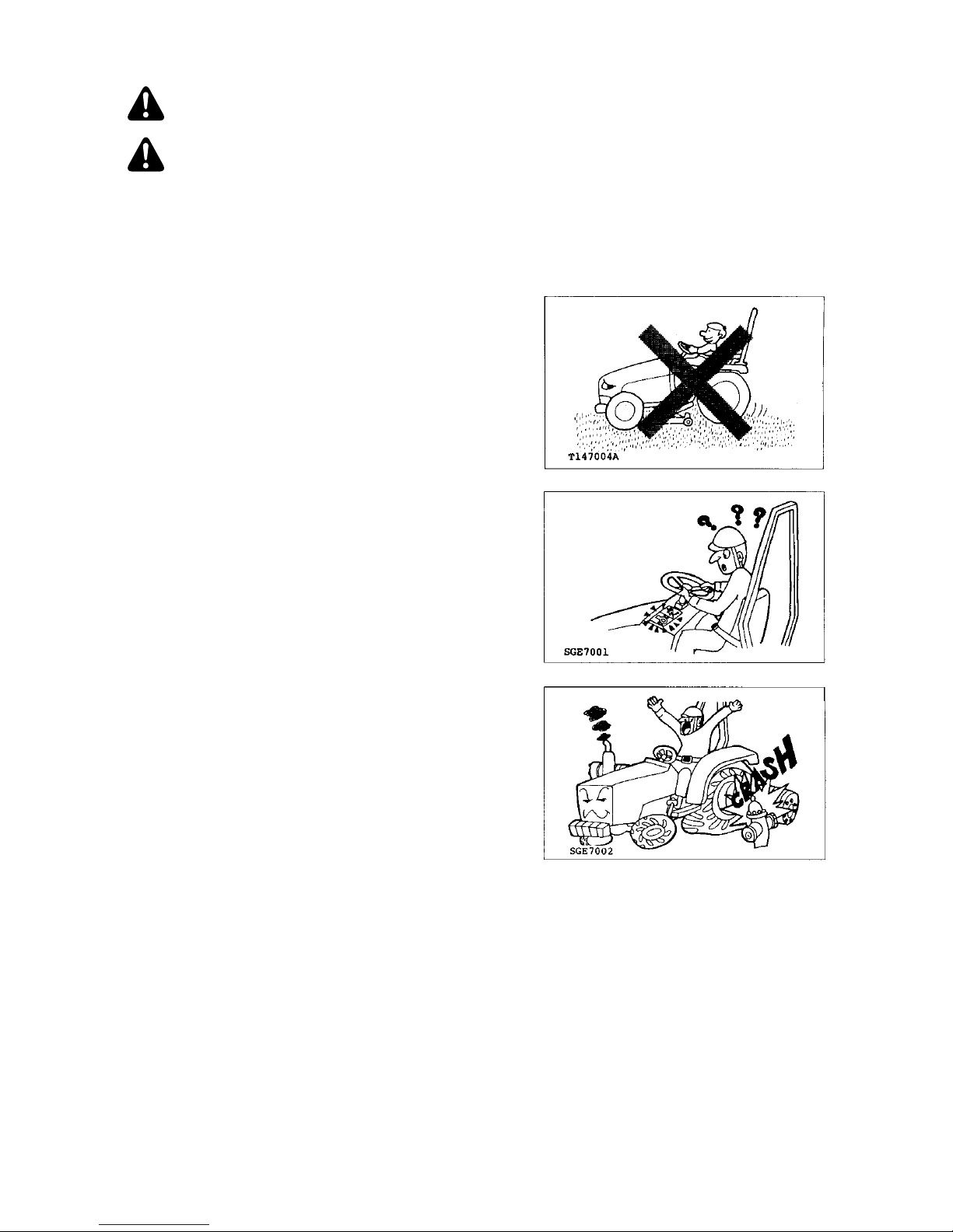
Know the positions and functions of all controls and the
meaning of any identification symbols on your controls,
gauges, and indicators before attempting to operate the
tractor.
Know how to stop the engine in an emergency.
Make sure you understand the capabilities, operating
characteristics and limitations of the tractor and
implement, such as maximum ballast weight, hydraulic
lifting capacity, speed, turning radius, operating
clearances etc.
Do not add extra ballast weight to compensate for a
load that is too heavy.
Page 8
EF393T OM
2
PROTECT OPERATOR SAFELY
Install an approved Roll-over Protective Structure
(ROPS) for safe operation. If a tractor rolls over without
a ROPS, death or serious injury is likely.
Always fasten the seat belt while operating the tractor
with Roll-over Protective Structure (ROPS) up.
Do not use the seat belt if the foldable Roll-over
Protective Structure (ROPS) is in the folded position or
the tractor does not have the Roll-over Protective
Structure (ROPS).
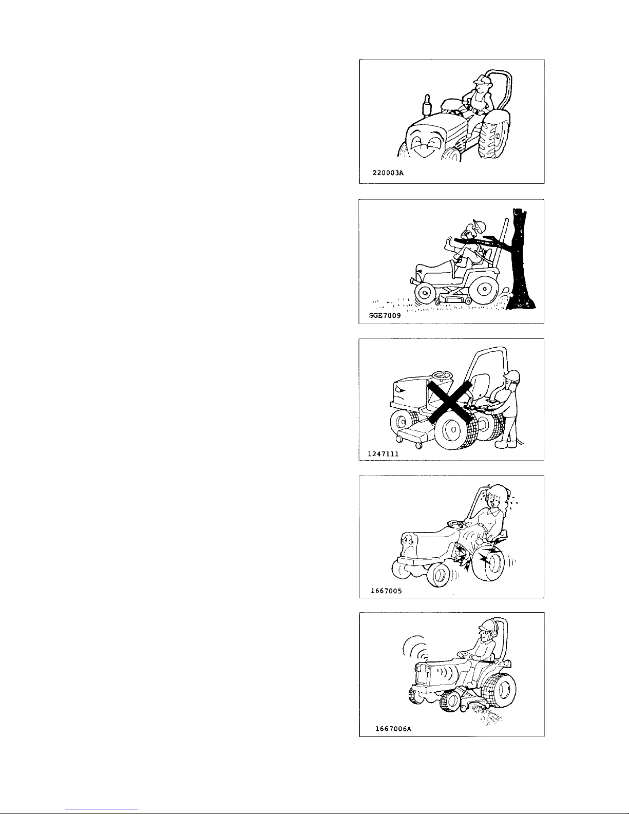
Extreme caution is required when operating a tractor
around trees or other overhead obstructions, such as
guy wires or power lines. Interference between the
ROPS and these obstructions may cause the tractor to
tip backwards.
Do not modify any structural portions of the ROPS by
welding, bending, grinding or cutting them. If any
component of the ROPS is damaged or involved in a
rollover incident, replace it with a complete new cage.
Do not attempt to repair the original one. Damaged or
modified structural parts impair the strength of the
ROPS and may lead to injury.
Avoid loose fitting or baggy clothing, torn clothing,
bulging pockets, frayed edges or heavy cuffs. Loose
frayed and bulky clothing can easily become entangled
in rotating parts. Wear work clothes and work shoes or
boots. Also you may need a: SAFETY HELMET,
SAFETY SHOES, EYE PROTECTION, HEAVY DUTY
GLOVES, HEARING PROTECTION, REFLECTIVE
CLOTHING, OR A RESPIRATOR/FILTER MASK.
Wear whatever safety gear and clothing is necessary
for the job.
Prolonged exposure to loud noise can cause
impairment or permanent loss of hearing. Wear a
suitable hearing protective device such as ear
protectors or earplugs to protect against objectionable
or uncomfortable noise.
Page 9
EF393T OM
3
BEFORE OPERATING
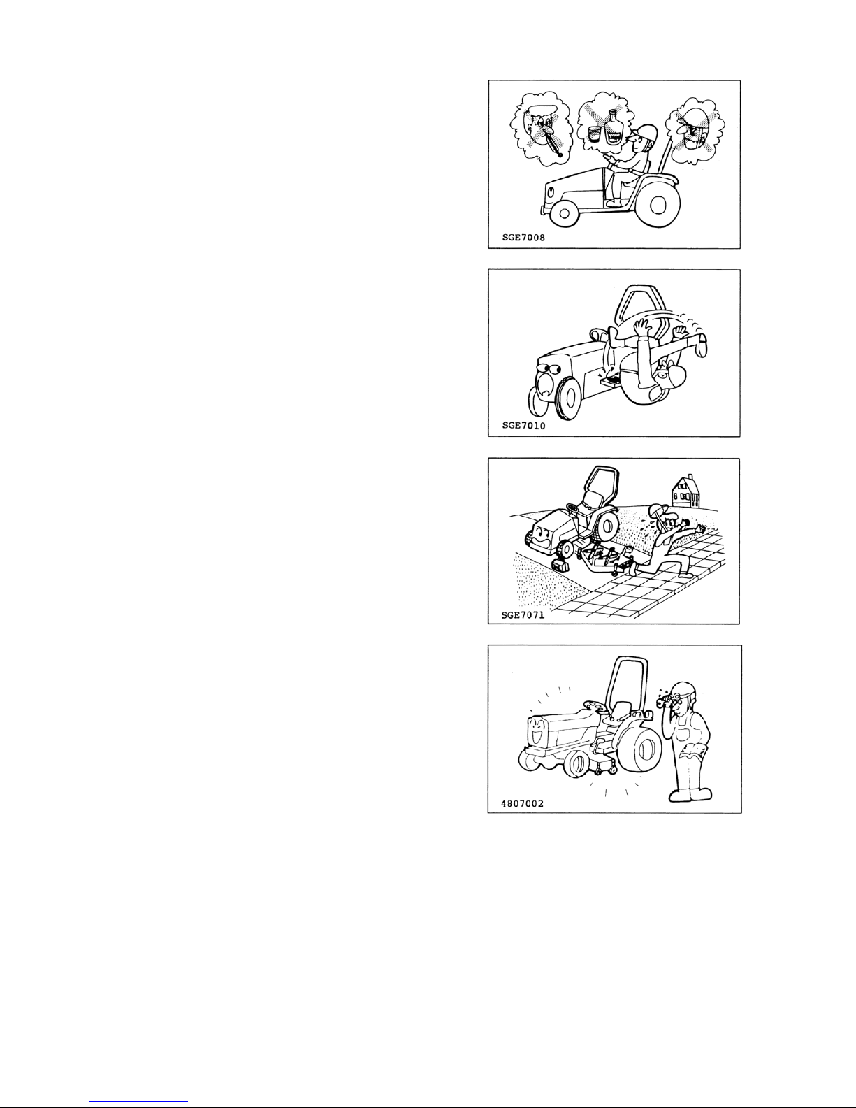
Do not operate the tractor when tired, sick, sleepy,
drunk, feeling overworked, taking medicine, pregnant,
suffering from mental disease or if other improper
conditions are present. These conditions impair a
person’s skill and judgment. When you begin feeling
tired while operating the tractor, take a 10-mi nute brea k
to stretch, walk about, lie down or snack. Do not
continue if you still feel tired after taking a break.
Remove oil, grease or mud from the hand rails, steps,
pedals, controls, and floor to avoid slips or loss of
control.
In winter, scrape off any ice or snow on the hand rails,
steps, pedals, controls, and floor .
To attach or remove an implement, refer to the
implement and tractor manufacturer’s manuals for the
proper procedures.
To unhitch an implement, move to a level area, lower
the implement to the ground and then block the
equipment in position before unhitching. If an
implement has wheels, block them to prevent it from
rolling.
Make sure
(1) The tractor and implements are in good
condition and properly adjusted.
(2) To check for loo sen ed bolts, adequate
lubricants, damaged or under-inflated tires,
safety shields and devices, steering and
braking linkages, hydraulic leaks, etc. Refer to
this manual for more detailed information.
(3) That implements are properly attached and
hooked up. Check that the PTO U-joint yoke
and locking devices are securely latched on
their shafts.
(4) That the tractor’s PTO speed matches the
implement’s specifications.
Page 10
EF393T OM
4
STARTING
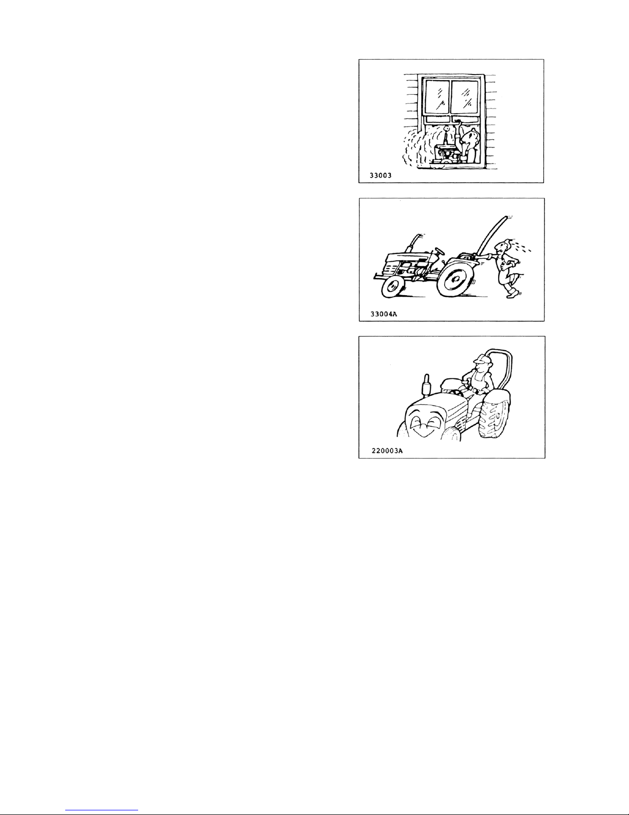
START THE ENGINE SAFELY
If you operate the engine inside a closed building, be
sure there is plenty of ventilation before starting the
engine. Exhaust fumes are poisonous. Carbon
monoxide is especially dangerous because it is
odorless and colorless. You can easily be overcome
without realizing it.
Always stay near the tractor and keep the parking
brake set securely while warming it up.
Only start the engine from the operator’s seat. Never
start the engine while standing on the ground.
Before you start the engine:
(1) Sit in the operator’s seat and adjust the seat
position if necessary.
(2) Make sure the ROPS is in working condition
and seat belt securely fastened.
(3) Lower any implement to the ground.
(4) Place speed shift lever and the PTO switch in
neutral.
(5) Set the parking brake.
(6) Disengage the PTO for the neutral position.
(7) Check all the instruments, gauges and indicator
lights.
(8) Be sure everyone is clear of the tractor and
implement.
Page 11
EF393T OM
5
DURING OPERATION
OPERATE THE TRACTOR SAFELY
Keep people and pets a safe distance away when
starting and operating the tractor and implement.
Do not permit any person other than the operator to
ride or board the tractor or implements, including any
wagons.
Do not play games with the tractor.
Never allow children to ride on your lap.
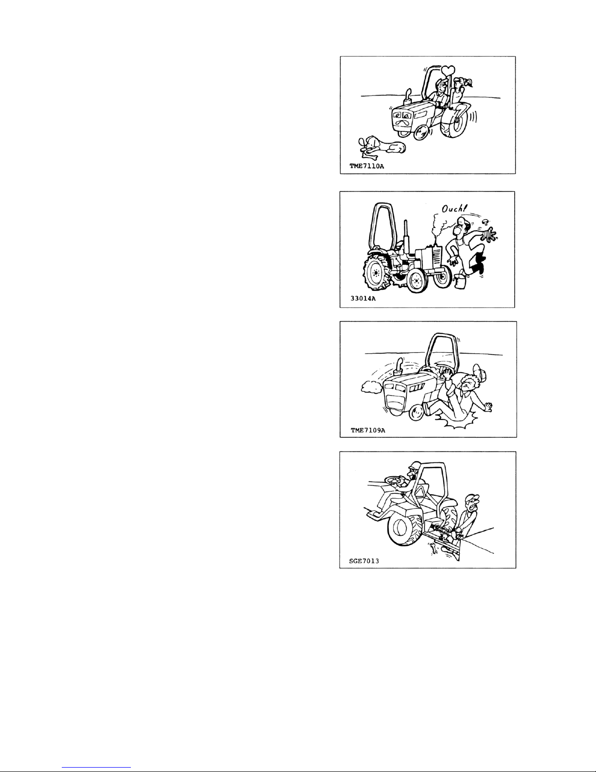
Do not touch the muffler, radiator, engine or other high
temperature parts before they have cooled down
completely.
Do not try to get on or off a moving tractor or
implements. Always use the hand rails and steps and
face the tractor when getting on and off.
Never use control levers as a hand hold and never step
on foot controls when getting on and off.
Do not get on the tractor with wet or greasy hands, or
muddy shoes. Do not jump off the tractor. Be aware of
slippery conditions on the ground.
Make sure you check the connecting points on your
equipment.
Keep hands, feet and clothing away from power-driven
parts. Keep others away from articulated joints, hitches,
drawbar, lift arms, PTO drives, cylinders, and anything
else that moves.
Never stand, or allow anyone else to stand, between
the tractor and an implement, unless the engine is
turned off and the parking brake is engaged securely.
Page 12
EF393T OM
6
OPERATE THE TRACTOR SAFELY (continued)
Oversized implements are dangerous for tractor
operation and are not safe for you. Refer to the
implement’s operator manual for the minimum and
maximum horsepower requirements and weights that
are allowed.
When using a heavy implement in front, always install
ballast or an implement on the rear for safe, stable
steering control.
When using a heavy implement on a rear 3-point hitch,
always install ballast or an implement on the front for
safe, stable steering control.
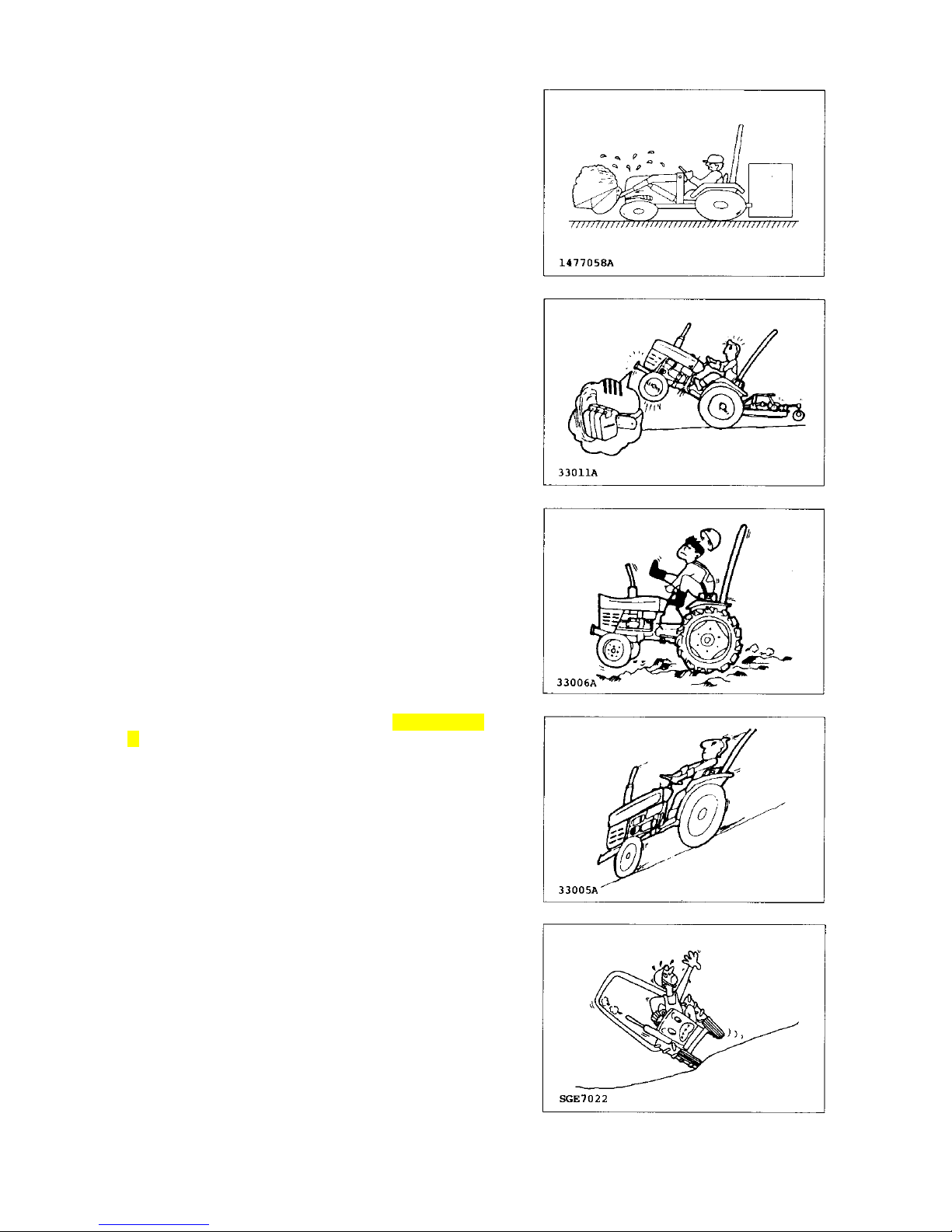
Slow the tractor down when crossing rough ground, tall
grass or weeds. Rocks, holes and stumps may be
hidden in the brush.
Do not let your tractor bounce. Y ou may lose steering
control.
Never use the tractor to round up farm animals.
Do not allow the tractor to coast downhill with the clutch
in, or with the gear shift in neutral.
When operating the tractor on a slope, set the wheel
tread as wide as possible for maximum stability, reduce
the engine speed and avoid quick application of the
brakes or sharp turns.
Stay off hills and slopes which are too steep.
Page 13
EF393T OM
7
AVOID TIPPING OVER
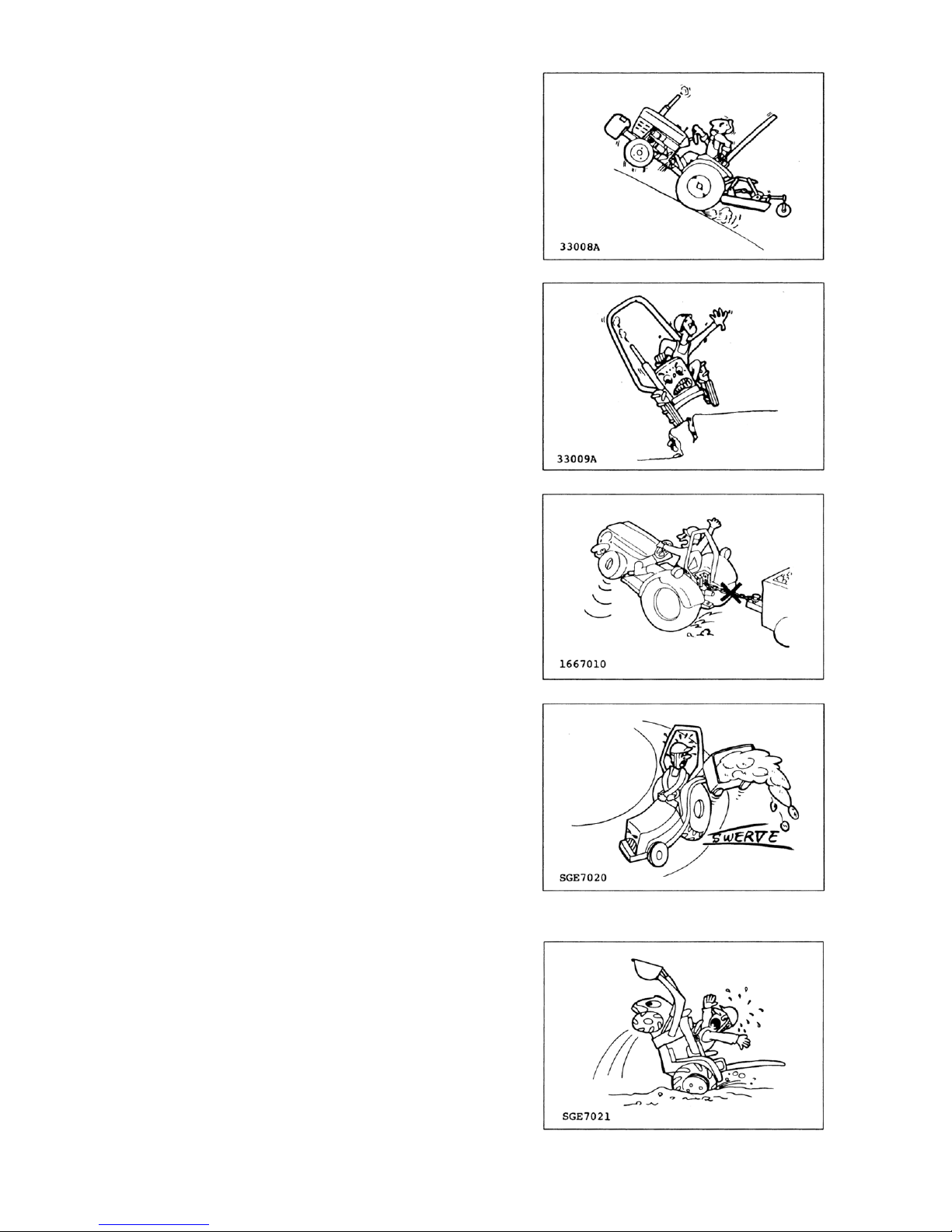
When starting the tractor on an uphill slope, shift to as
low a gear as possible and reduce the engine speed to
avoid tipping over backward.
Do not drive near the edge of a gully or a steep
embankment. Avoid holes, ditches, etc. which may
cause the tractor to tip over, especially on hillsides or
steep slopes.
When operating on slopes or rough uneven ground, it is
important to have as much distance as possible
between the wheels. Operate the tractor carefully at the
lowest speed.
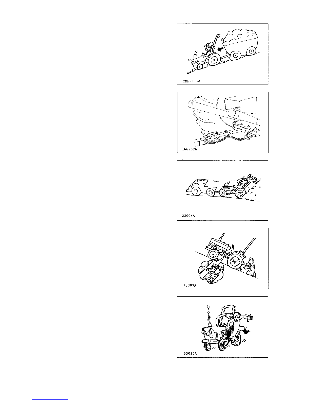
Do not pull carts etc. from the top link or the top link
hinge, rear axle, or any point above the drawbar. Doing
so could cause the tractor to tip over backward. Only
attach items to be pulled to the drawbar.
Use care when pulling loads or installing a heavy
implement.
(1) Only use approved hitch points.
(2) Limit loads to those which you can control
safely.
(3) Limit travel speeds so that you can control the
tractor safely.
(4) Do not turn too quickly.
(5) Use care when backing up.
(6) Install the amount of ballast recommended in
the operator’s manual.
Driving forward out of ditch or in muddy conditions, or
up a steep slope, could cause the tractor to tip over
backward. If the mud is deep enough it will keep the
wheels from turning. Then, the tractor will rotate up and
back around the axle very quickly. When stuck in
muddy conditions, do not remove the implement or
ballast weight. Always ba ck out.
Page 14
EF393T OM
8
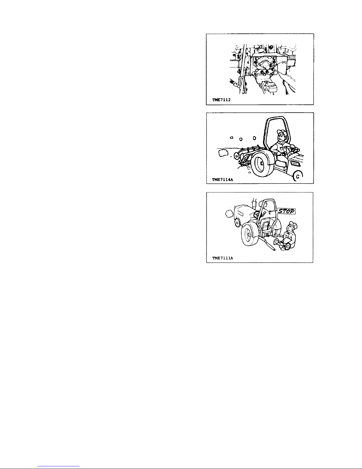
STAY CLEAR OF THE PTO
The PTO shaft safety guard (A) should be installed
when the PTO system is not in use.
Make sure that the tractor PTO speed matches the
implement’s required PTO speed.
Do not drive or operate the implement beyond the
tractor’s PTO speed.
Stop the engine and be sure the PTO has stopped
moving before:
(1) Connecting or disconnecting the PTO shaft.
(2) Making any adjustment to the PTO drive or
3-point hitch.
(3) Adjusting, cleaning or servicing PTO driven
implements.
Page 15
EF393T OM
9
TRANSPORTING
Raise all implements and place them in the
locked-for-transport position.
Do not drive the tractor on the road with implements in
motion.
Couple the brake pedals together for travel at road
speeds. (This only applies to models with two brake
pedals.)
Do not make sharp turns at road speeds.
Always dim your headlights when another vehicle is
coming toward you. Keep the lights adjusted so that
they will not blind the driver of another vehicle.
Before going down a steep hill, shift to the lowest speed
in order to control tractor with the least braking
possible. Do not coast downhill.
Do not stop or start suddenly when going uphill or
downhill.
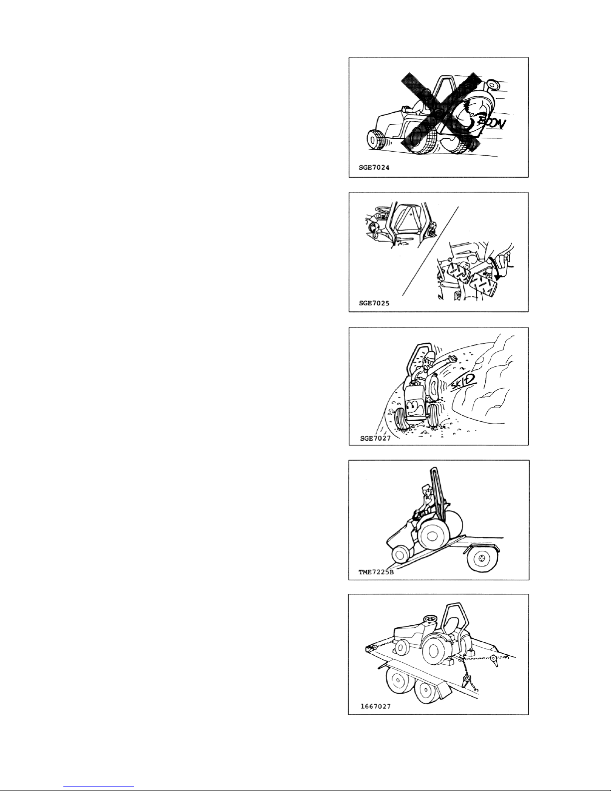
When loading (or unloading) the tractor onto a vehicle,
use care as follows:
(1) Use a strong loading ramp or loading dock.
(2) Use the lowest reverse speed and drive up the
loading ramp backward.
(3) Set the parking brake and place wheel blocks
firmly under the vehicle’s wheels.
(4) Do not try to drive onto a trailer from the bank of
a ditch.
Secure the tractor and any other load with chains. Be
sure they are tight.
If chains are not available, use rope, wire, blocks, or a
winch cable. Check the load after traveling a few
kilometers, and every 100 km thereafter, to make sure
that the ties are not coming loose. Also, check after
rough bumps in the road.
Page 16
EF393T OM
10
TOWING
When towing a load that weighs more than the tractor,
the trailer should have its own brakes. When towing,
drive slowly, avoid hills and apply the brakes gently.
A safety chain will help control an implement being
pulled if it accidentally separates from the drawbar
while traveling. Using appropriate adapter parts, attach
the chain to the tractor drawbar support or to some
other specified anchor location. Leave only enough
slack in the chain to permit turning.
Do not tow the tractor faster than the tractor’s
maximum travel speed in the highest gear, and never
more than 25 km/h (16 mph).
Check local regulations concerning towing. Towing is
illegal in some countries.
AFTER THE DAY’S OPERATION
PARK THE TRACTOR SAFELY
Park tractor on a firm level surface.
When parking the tractor, couple the brake pedals
together and set the parking brake securely. When you
must park on a slope, position the tractor at a right
angle to the slope and set the parking brake securely.
Then, block both the front and rear wheels.
Take all possible precautions as follows when leaving
tractor unattended:
(1) Disengage the PTO and lower any implement to
the ground.
(2) Move all shift levers to neutral.
(3) Couple the brake pedals together and set the
parking brake lever.
(4) Run the engine for 2 to 3 minutes at one-third
throttle speed and no load in order to cool it.
(5) Stop the engine and remove the key.
(6) Cycle the hydraulic controls to eliminate any
residual pressure.
Page 17
EF393T OM
11
MAINTENANCE AND SERVICE
AVOID EXPLOSIONS OR FIRES
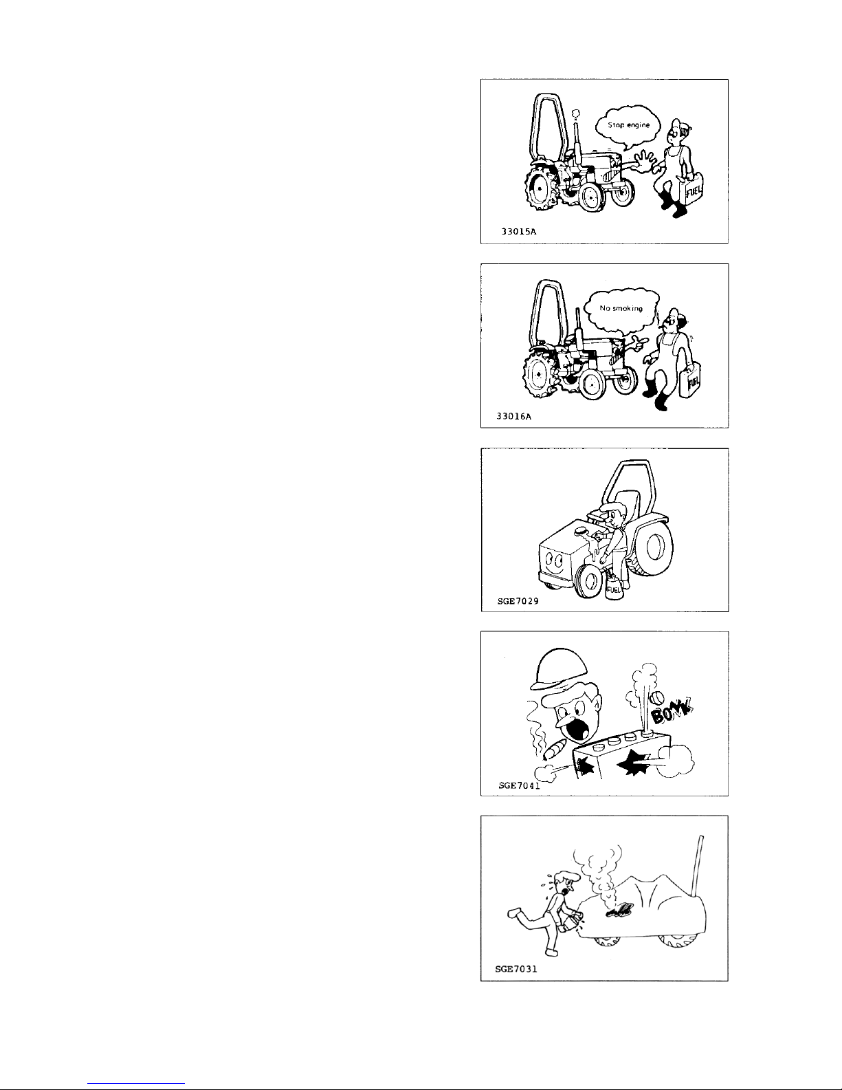
Refuel the tractor when the engine is cool and in a
well-ventilated area, preferably outside.
Never fill the fuel tank with the engine running.
Be sure to use the correct type and grade of fuel.
Keep all sparks, flames and smoking materials well
away while handling fuel.
Ground the fuel funnel or nozzle against the filler neck
on the tractor to prevent sparks.
Do not overfill the tank or spill the fuel. If fuel is spilled,
wipe it up immediately . Install the fuel tank cap securely
after refueling.
Be sure there is plenty of ventilation before charging
the battery. Gas produced while charging the battery is
explosive.
Keep all sparks, flames, and smoking materials well
away from battery. Hydrogen gas at a concentration as
low as 7 per cent can explode in the presence of a
spark or open flame and spatter acid.
Use a flashlight to check the battery electrolyte level.
Never use an open flame or match to check.
Keep the engine clean and free of grass, leaves, or
excessive grease.
Let the engine cool down before storing the tractor in
an enclosure or covering it with a sheet.
Page 18
EF393T OM
12
MAINTENANCE AND SERVICE (continued)
Do not service the tractor while it is in motion or while
the engine is running.
Before servicing the tractor, always set the parking
brake, block the wheels, lower the implement, release
all hydraulic pressure and place all the controls in
neutral.
Use only the correct tools and equipment.
Unauthorized modification to the tractor may impair its
function, create an unsafe situation and reduce the
tractor’s useful working life.
Do not use substitute parts that may not meet the
strength and design requirements or may not fit the
tractor.
Do not use repair parts not approved by YANMAR.
Remove the radiator cap only when the coolant
temperature is low. Wait at least one hour after
operation, to allow the coolant to cool down.
Cover the radiator cap with a cloth before opening it
and release the pressure gradually before completely
removing the cap.
Do not service the hydraulic system when the hydraulic
oil is hot.
Do not set the relief valve pressure higher than stated
in the tractor or implement specifications.
Do not close off the overflow or bypass lines.
Page 19
EF393T OM
13
MAINTENANCE AND SERVICE (continued)
Hydraulic oil or diesel fuel escaping under pressure can
penetrate the skin and cause serious injury. Before
disconnecting any lines, be sure to relieve all pressure.
Before applying pressure, be sure all connections are
tight and all components are in good condition.
Fluid escaping under pressure from a very small hole
can be almost invisible. Wear safety goggles for eye
protection and use a piece of cardboard to check for
suspected leaks. Do not use your hands. If injured by
escaping fluid, see a doctor at once. Serious infections
and other problems can develop if proper medical
treatment is not administered immediately.
Disconnect the battery ground cable before working on
the electrical system or working in any area where you
might come into contact with electrical components.
Disconnect the ground cable first and reconnect it last.
The sulfuric acid in a battery is poisonous. It can
destroy clothing and burn the skin. Wear eye protection
and rubber gloves when filling the battery. If you spill
acid on yourself, flush your skin with water and apply
baking soda or lime to neutralize the acid. Then seek
medical attention right away. If acid is swallowed, get
medical attention immediately!
Page 20
EF393T OM
14
Storage
Whenever the tractor will not be used for a few months,
do the following:
(1) Drain the fuel tank.
(2) Lower any implement still attached.
(3) Set the parking brake and block the wheels.
(4) Remove the battery and store it in a cool, dry
place, out of the reach of children.
CAUTION
ALWAYS BE ENVIRONMENTALLY
RESPONSIBLE
Follow the guidelines of the governmental agency
for the proper disposal of hazardous materials such
as engine oil, diesel fuel, engine coolant and,
machine fluid, grease.
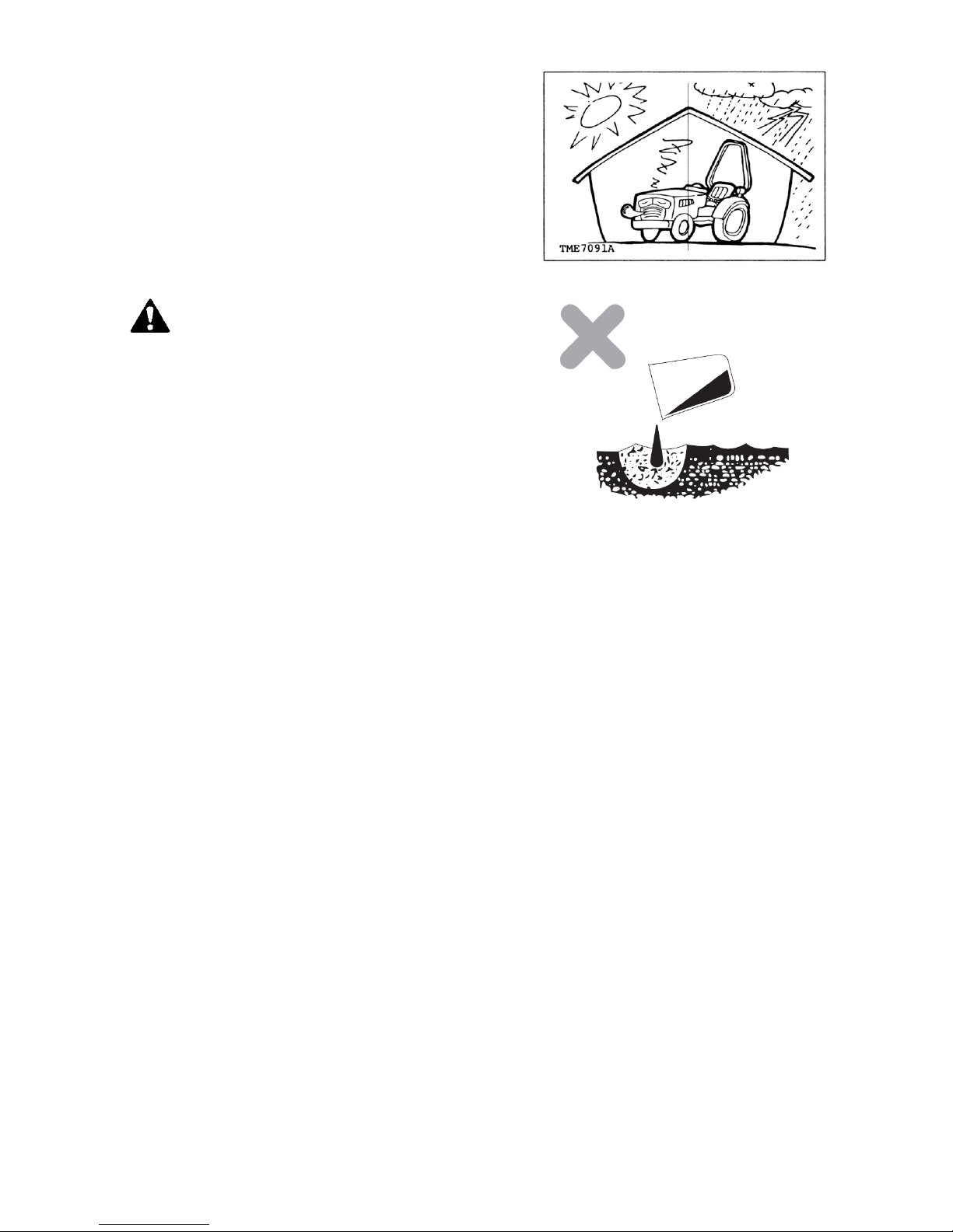
NEVER dispose of hazardous materials
irresponsibly by dumping them into a sewer, on the
ground, or into groundwater or waterways.
Failure to follow these procedures may seriously
harm the environment.
Comply with legal regulations and guidelines for
disposal of: empty containers for fuel, cooling water
(coolant), oil, grease; fuel/oil filters; batteries;
machine itself; machine accessories; and
packaging materials.
Page 21
EF393T OM
15
AFTER SALES SERVICES
After sales services
When your tractor is not working normally, check it
referring to the troubleshooting section. You can of
course consult with your service representative.
Whenever you ask service to your service
representative, following information are very helpful to
identify your tractor.
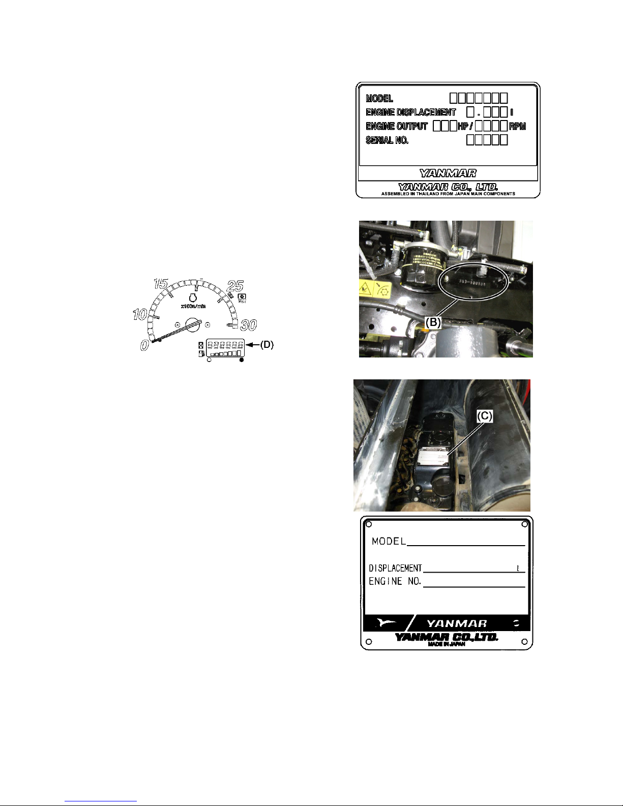
1) The label of tractor model name and serial number
(A) is on the left rear fender and the stamp of the
serial number (B) is on right side of front frame.
2) Engine model name and serial number (C).
3) Hour-meter (D) shows estimated hours of
operation. Turn on key switch to read hours.
4) Operating conditions.
Kind of work and implement used when a problem
is happened.
5) Any other information when a trouble is occurred.
Noise, vibration, function etc.
Availability of spare parts
Maintenance parts or spare parts are available for 10
years after the production of this tractor series has
been discontinued. However, special parts will be
subject to consultation. Yanmar may be able to supply
a particular part after the normal supplying period.
(A) Tractor model name & serial number
(B) Tractor serial number
(C) Engine model name & serial number
Page 22
EF393T OM
16
WARNING
Do not move the tractor if the wheel mounting bolts or
nuts are loose. If the tractor is driven with loose nuts or
bolts, there is a possibility that an accident will occur.
Make daily and periodic wheel inspections to check for
loose nuts and bolts on the wheels. If they are loose,
retighten them to the specified torque.
IMPORTANT
The first 50 hours of handling and maintenance greatly
affect the service life and performance of a new tractor. In
particular, pay special attention to the following points
during this period of time.
(1) Refrain from sudden acceleration and sudden
braking.
(2) Do not increase the speed too much or carry any
more load than is necessary.
(3) Operate the tractor only after the engine has warmed
up sufficiently.
(4) Slow down on a rough road or on a slope.
(5) Check the tightness of the wheel mounting bolts
after the first 10 hours and again after the first 50
hours. If they are loose, retighten them. (For specific
tightening torques, refer to the table in the instruction
manual.)
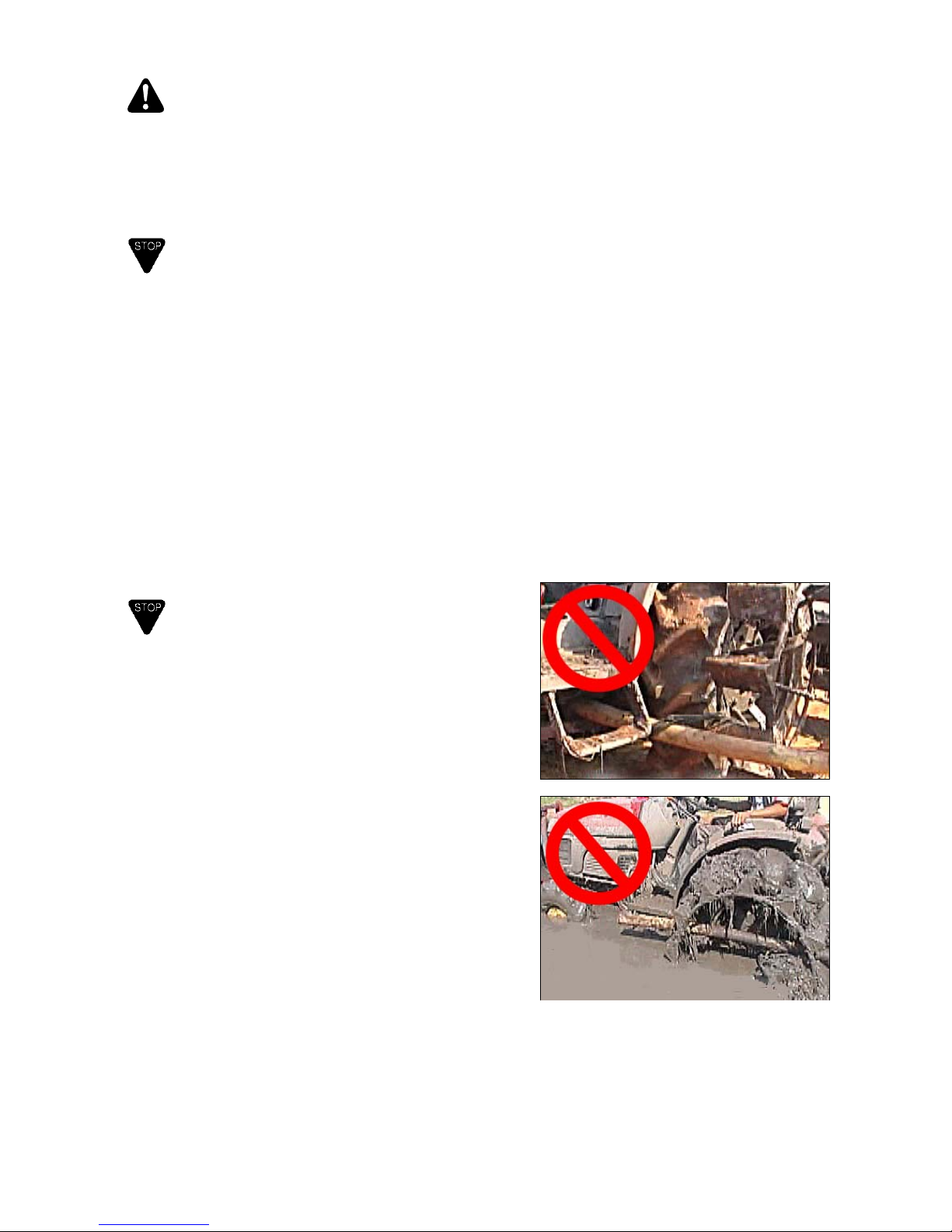
IMPORTANT
When the tractor gets stuck in a muddy portion in field, do
not tie a piece of lumber, log or pipe to the front or re ar
wheels to drive out of the muddy portion.
It may break transmission and/or rear axle inner parts or
cases.
Put a ladder bridge under the wheels and then drive out.
Or use strong rope or chain to pull it out of the muddy
portion slowly by the other tractor or so.
Note:
These photos show rear tire with cage
wheel.
Page 23
EF393T OM
17
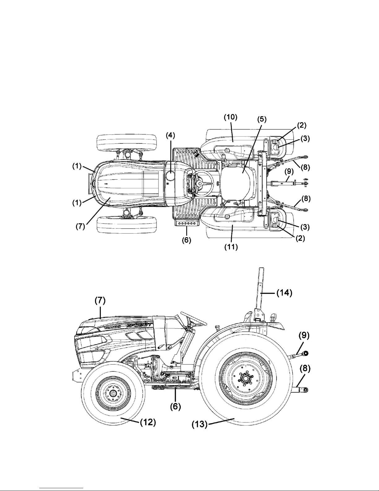
TRACTOR OUTLINE
(1)
(2)
(3)
(4)
(5)
(6)
(7)
Head light
T urn signal lamp
Tail lamp
Fuel refill port
Operator’s seat
Sub-step
Bonnet
(8)
(9)
(10)
(11)
(12)
(13)
(14)
Lower link
T op link
Fender, R
Fender, L
Front tire
Rear tire
ROPS (Safety frame)
Page 24

EF393T OM
18
PARTS NAMES
(1) Main switch
(2) Accelerator lever
(3) Parking brake lever
(4) Combination switch
Head light, turn signal, horn
(5) Reverser lever
(6) Clutch pedal
(7) Range gear shift lever
(8) PTO gear shift lever
(9) Brake pedal connector
(10) Brake pedal
(1 1) Foot accelerator pedal
(12) Main gear shift lever
(13) Position control lever
(14) Differential gear lock pedal
(15) Seat adjust lever
(16) Stop & slow return valve
(17) Front wheel drive lever
(18) Seat belt
Page 25

EF393T OM
19
Meter panel indicators
(1) Fuel gauge
(2) Engine coolant alarm lamp
(3) Engine speed meter, RPM
(4) Hour meter
(5) Battery charge pilot lamp
(6) Engine oil pressure pilot lamp
LABEL LOCATIONS
Keep the safety instructions labels clean and clearly visible for your safety. If any of them are damaged or
missing, replace them with new ones.
(1) 1A8310-65340
Label, fire caution
(2) 198163-65930
Label, caution muffler
(3) 1A8310-65310
Label, caution
(4)198283-65651
Label, Thailand only
(5) (6) 1A7874-65360
Label, brake coupling
(13) 1A8310-65300
Label, warning escape
Page 26

EF393T OM
20
(7) 198163-65930
Label, caution muffler
(8) 198163-65940
Label, safety cover
(9) 1A6150-93151
Label, PTO shaft cover
(10) 198163-65350
Label, danger shaft rotate
(1 1) 198163-65950
Label, seat belt
(12)
Page 27

EF393T OM
21
CONTROLS
ENGINE
Main switch
The switch is used to turn on and off the engine
OFF
The electric current is shut off.
The engine stops. (The key can be
removed.)
(5) Battery charge lamp
(6) Engine oil pressure lamp
ON
The electric current is on. If the engine is
stopped, the engine oil pressure lamp (6)
and battery charge lamp (5) turn on.
START Starter motor runs to start the engine, when
range shift lever is at neutral.
Release the key when the engine starts and
the key returns to the “ON” position
automatically.
Accelerator lever
The accelerator lever (A) is used to increase or
decrease the engine speed or keep the engine at a
constant speed.
(A) Accelerator lever
(S) Slower engine speed
(F) Faster engine speed
Accelerator pedal
The accelerator pedal (A) is used to increase or
decrease the engine speed, mainly during travel on a
road. To increase the engine speed, depress the pedal.
(A) Accelerator pedal
Page 28

EF393T OM
22
TRAVELLING, PTO RE RELATED FUNCTIONS
Main shift lever
The transmission has 4 main gear shifts.
Depress the clutch pedal fully, and move the lever to
desired position.
(A) Main shift lever
IMPORTANT
Be sure the tractor stops whenever shifting. If not, it
may cause damage to transmission gears.
Range shift lever
The transmission has 2 range gear shift aside from 4
main gear shifts.
(B) Range shift lever
2: High Speed range
1: Low speed range
N: Neutral
IMPORTANT
Be sure tractor stops when shifting. Do not change
Range shift lever while moving.
Reverser lever
Reverser lever changes the direction of travel of the
tractor, forward or reverse. Depress the clutch pedal
and stop tractor whenever shift the lever.
Lift up the lever to put it in a required position.
(A) Reverser lever
F: Forward
N: Neutral
R: Reverse
WARNING
Be sure to stop the tractor when shifting. Never
change Reverser lever while moving. Sudden change
of running direction back and forward may cause
serious injury.
Page 29

EF393T OM
23
PTO shift lever
The transmission has 2 PTO speeds. To change the
speed, depress the clutch pedal fully.
(C) PTO shift lever
PTO speed at engine 2,800 rpm
1 584 rpm
2 836 rpm
CAUTION
Strictly maintain the PTO speed as specified by the
implement. Otherwise, the implement or transmission
can be damaged and may cause an injury.
Brake pedal
Tractor has brake pedals for right and le ft turn
independently and they can be applied separately.
For a sharp turn in the field, depress the brake in which
direction you want to turn. For driving on a road, be
sure to connect both pedals with the connector.
To avoid unnecessary wear of brake discs, do not rest
foot on the brake pedal during operation.
(A) Brake pedals
(B) Brake pedal connector
WARNING
Be sure to connect the both brake pedals with the
connector when driving on a road. Tractor may turn
over by one-sided braking in high speed.
Parking brake lever
To apply parking brake;
Connect brake pedals, depress brake pedals and raise
parking brake lever.
To release parking brake;
Depress brake pedals slightly and down parking brake
lever.
(A) Parking brake lever
(B) Brake pedals
(C) Brake connector
(L) Apply parking brake
(R) Release parking brake
CAUTION
Be sure to connect the both brake pedals with the
connector when applying parking brake. If not, only
left tire is locked and it may not brake tractor
sufficiently.
Page 30

EF393T OM
24
Clutch pedal
The clutch is a device for connecting and disconnecting
engine power to the transmission.
To disconnect engine power to the transmission,
depress the clutch pedal fully.
To connect the engine power, release the clutch pedal
gradually and the engine power transmits to
transmission.
IMPORTANT
Do not rest your foot on the clutch pedal while
operating. The clutch disc may wear prematurely.
(A) Clutch pedal
Differential gear lock pedal
A differential gear system is equipped on front and rear
axles of this tractor for smooth turning.
Depressing this pedal locks rear axle differential gear
box and rear wheels rotate as if right and left axles are
connected. When one side rear wheel spins and the
other does not rotate, depress the pedal to lock the
differential gear for escaping.
To unlock differential, release the depressed pedal.
IMPORTANT
When differential gear is locked, drive tractor slow
speed and keep going straight. Never steer tractor
while depressing the pedal.
WARNING
Never fail to unlock the differential gear after escaping
from the place. Otherwise, you cannot make an
intended turn and an accident may result.
(A) Differential gear lock pedal
(R) Release lock (release pedal)
(L) Lock differential gear
(keep depressing pedal)
Front wheel drive lever
The lever engages or disengages front wheel drive.
Depress clutch pedal and move the lever when tractor
stops.
(A) Front wheel drive lever
(2w) OFF: Two-wheel drive
(4w) ON: Four-wheel drive
IMPORTANT
Be sure to stop the tractor whenever move the lever.
Disengage front wheel drive when drive with high gear
on a road, hard surface place or towing trailer. The
front tire may wear prematurely or front axle gears may
break in case of heavy braking.
Page 31

EF393T OM
25
HYDRAULIC SYSTEM
Position control lever
Position control lever holds desired height of a rear
hitched implement.
Lever stopper (B) limits lowering an implement to limit
the working range of the lever, or when t raveling o n
road.
(A) Position control lever
(B) Lever stopper
(C) Raise
(D) Lower
Hydraulic stop and slow return valve
The stop and slow return valve controls lowering speed
of implement.
(A) Hydraulic stop and slow return valve
(C) The lowering speed of implement becomes
slower and it stops hydraulic flow when turned
fully.
(O) It opens the valve and the lowering speed of
implement becomes fast (normal speed).
IMPORTANT
When driving on a road with rear hitched implement,
open the hydraulic stop and slow return valve and fix
the hydraulic control lever in raise position with stopper .
Do not operate the hydraulic control lever when the
valve is fully closed. Otherwise, it may damage
hydraulic parts.
Page 32

EF393T OM
26
ELECTRIC SYSTEM
T urn signal switch
Turn signal functions when key switch turns on.
Turn the turn signal switch anticlockwise to blink right
side turn signal lamp and turn clockwise to blink left
side lamp.
(A) Turn signal switch
(R) Right lamp blinks.
(L) Left lamp blinks.
Head light switch
Headlights turn on when key switch turns on.
Turn head light switch clockwise to turn on head lights.
(B) Light switch
(OFF) Headlights turn off.
(L) Headlights turn on with low beam.
(H) Headlights turn on with high beam.
CAUTION
When there is an oncoming vehicle in night time, be
sure to switch to low beam position. If keep on high
beam, it may cause traffic accident.
Horn button
Horn functions in any positions of the key switch.
Push horn button to blow horn.
(C) Horn button
Page 33

EF393T OM
27
INSTRUMENT PANEL
(1) Fuel gauge
(2) Engine coolant alarm lamp
(3) Tachometer
(4) Hour meter
(5) Battery charge pilot lamp
(6) Engine oil pressure pilot lamp
(1) Fuel gauge
It indicates fuel level remained in fuel tank when key switch turns on.
(a) Full
(b) 1/2
(c) Empty soon
(d) Empty warning
The fuel tank will be empty in a short time.
The indicated amount is approximate.
(2) Engine coolant alarm lamp
It indicates engine coolant temperature.
If the lamp turns on, reduce engine speed to idling and wait for cooling
down. Find out the cause and call your dealer if necessary.
When the lamp is;
(1) turning on: 100 degree centigrade
(2) blinking: 110 degree centigrade or short circuit
(3) T ach ometer
Indicates engine speed in revolution per minute (RPM).
It also indicates PTO shaft speed 540rpm when the needle stands at
the yellow mark in the position 1 of PTO shift lever.
(A) Yellow mark
(4) Hour meter
It shows actual operating time of the engine in hourly unit. It counts
whenever the engine is running. For example, 10.5 means 10 hours
and 30 minutes of the engine running time.
(5) Battery charge pilot lamp
This lamp lights when the key switch is in “ON” position.
The charge lamp turns off when engine starts. If the lamp does not
turn off at 1500rpm engine speed or higher, see your dealer.
(6) Engine oil pressure pilot lamp
This lamp lights when the key switch is in “ON” position and goes of f
when the engine starts. If the lamp does not turn off after engine
starts, stop the engine immediately and check oil level. If oil level is
sufficient, see your dealer.
Page 34

EF393T OM
28
OTHERS
Seat adjust lever
It adjusts the operator’s seat position in 5 steps backward
or forward.
Raise the lever and slide forward or backward to desired
position. Lower the lever to latch the seat.
(A) Seat adjust lever
Seat belt
WARNING
Always fasten seat belt while operating the tractor with
the Roll-over Protective Structure (ROPS).
Do not use the seat belt if the tractor does not have the
ROPS.
(A) Seat belt
(B) PRESS button
Fasten the seat belt properly without twisting. Adjust the
belt length to operator figure.
Press “PRESS” button on the buckle to unfasten seat belt.
Opening bonnet
(1) Raise the lever to open bonnet. The bonnet goes up
and is hold with gas damper.
(A) Bonnet open lever
(B) Gas damper
Page 35

EF393T OM
29
OPERATIONS
1. Pre-operation checks
DANGER
1) Never smoke or use bare lamps/lights during oil
replenishing.
2) Never fill fuel oil while the engine is running or hot.
3) After filling fuel, be sure to cover the fuel tank with
screw-top and wipe off spilled fuel. If not, a fire may be
caused.
4) Check the fuel lines daily. Fuel leaks on a damaged
fuel line.
WARNING
1) Whenever servicing the tractor, place it on a flat and
leveled area. Be sure no traffic neither people around
the tractor. Otherwise, the tractor can cause an
unexpected accident.
2) Whenever servicing under rear hitched implement,
close hydraulic stop and slow return valve (A) and place
lock device or support to the implement. Otherwise the
implement may fall down incidentally and it can cause
injuries.
(C) Close
CAUTION
1) Never fail to stop the engine before checks or
maintenance. If not, you may be trapped in a rotating
part and heavily injured.
2) To check or service the tractor, wait until the engine and
muffler are cooled down. If not, you may got burned
and be injured.
3) Never fail to reinstall covers and parts detached for
service. Otherwise, you may be trapped in the tractor
and heavily injured.
Page 36

EF393T OM
30
For safety reasons, always check the tractor before
day's work. Remove any abnormalities.
At least check the followings in order:
(1) Abnormalities in previo us day
(2) Walk around the tractor to look into:
• Deformed, damaged, wearing or lost exposed parts
• Air inflation pressure and wear of tires
• Loosened or lost bolts and nuts of the tire rims and
disks
(3) Check inside the bonnet
• Engine oil level and leaks.
• Fuel oil amount, leak and damages on fuel lines.
• Engine coolant level, leaks and damage on
lines.
• Battery electrolyte (liquid).
Depending on battery type;
Check electrolyte level, to be between upper and
lower limit.
Check the color of the hydrometer , to be green.
• Clogging or dirt in air filter.
• Tension or damage of cooling fan belt.
Page 37

EF393T OM
31
• Radiator screen, grille and engine room for dust.
• Hydraulic joint and lines for damages and loose
connection.
• Check electrical wirings for wear or damages of
lead sheaths and loose connections.
(4) Check operating system
• Play of brake pedals.
Brake pedals must have reasonable play (A)
and plays of both right and left brake pedals
must be equal. (25-35mm)
• Play of clutch pedal.
Clutch pedal must have reasonable play (A).
(15-25mm)
• Play of steering wheel.
Steering wheel must have reasonable play (A).
(20-50mm)
Page 38

EF393T OM
32
(5) Check hitched implement
• PTO Drive shaft lock pin must be in groove of
PTO output and input shafts.
• Pins must be inserted in proper positions.
• Loosened bolts and nuts.
• Damaged or worn parts.
• Connection of 3-point linkage.
(6) Start the engine and check:
• Abnormal sound or noise.
• Color and smell of exhaust gas.
• Function of each lamp, gauge and meter
Page 39

EF393T OM
33
2. Break-in (initial 50 hours)
The new tractor should be carefully operated for the first 50
hours. It will surely have an effect on the lifetime and
performance of the tractor throughout the life. Pay attention
to the following points in particular:
(1) Avoid quick start or abrupt brake if it is not in
emergency case.
(2) Do not operate in higher speed or heavier load more
than necessary. Do not operate with full load.
Avoid from operation such engine speed comes down
by a load or smoke while working.
(3) Start operation after the engine is sufficiently warmed
up.
(4) Slow down on the rough road or slope.
(5) Check tire fixing bolts at the first 10 hours and 50
hours operation. If loosened, tighten it.
See “12. Wheel tread” for bolt tightening torque.
(6) Check the tractor at the time of first 50 hours
operation.
3. Before starting
WARNING
1) Before starting the engine, sit on the operator’s seat and
make sure shift levers (reverser, PTO shift, range shift,
main shift) are at neutral position, and position control
lever is at down position. Negligence may cause tractor
sudden start and serious injury.
2) Do not run engine in a closed room. Run the engine in
well-ventilated area. If you are forced to start the engine
in a confined room, make sure the ventilation is proper.
Exhaust gas is poisonous and it can lead to death.
CAUTION
1) Before and after operation, never fail to check and service
the tractor. Particular check will be required at brake
pedals, controls, steering devices and tire rim fitting bolts.
Negligence can cause a heavy injury or accident to the
tractor and the human.
2) Set the parking brake during the warm-up operation.
Otherwise the tractor may abruptly start to run.
Page 40

EF393T OM
34
4. Start and stop
4-1. Start and stop engine
Start engine
IMPORTANT
1) Do not run the engine starter motor for more than 10
seconds. It may cause a breakage of the starter
motor. If the engine does not start, keep it cool for
2-5 minutes before retry. Then, execute steps (3) (4).
2) Never turn the main switch to start position while
engine is running.
(1) Open the fuel cock of water separator (A).
(A) Water separator
(B) Fuel cock (O) Open
(2) Put the reverser lever and PTO shift lever to ”N”
position.
(3) Set position control lever in the LOW position.
Make sure that the implement is lowered.
(4) Push accelerator lever forward to higher speed
position.
(5) Insert the key and turn it to “ON” position.
Check pilot lamps on meter panel;
(A) Battery charge pilot lamp is on.
(B) Engine oil pressure pilot lamp is on.
(6) Turn the key switch to “START” position.
(7) As engine starts, immediately release key switch and it
goes back to “ON” position automatically.
When engine starts, battery charge and engine
pressure pilot lamps turn off.
(8) Warm up the engine by running without load at 1500
rpm for about 5 minutes. Especially if the temperature
is below 0°C, at least 10 minutes warm-up is required.
(A) Reverser lever
(C) PTO shift lever
(A) Position control lever
(A) Accelerator lever
Page 41

EF393T OM
35
Stop engine
(1) Pull accelerator lever (A) rearward (S) to decrease
engine speeds.
(2) Turn key switch to “ OFF” position.
(3) See main shift lever, range shift lever, reverser
lever and PTO shift lever are in neutral positions.
IMPORTANT
Sudden stop of heated engine may cause engine
overheating. Prior to stop engine, keep engine
running at 1200 - 1500 rpm for about 2 minutes to cool
down.
(A) Accelerator lever (S) Slow speed
4-2. Start, gear shifting and stop tractor
Start tractor
(1) Be sure right and left brake pedals are connected
by connector.
(2) Set engine speed about 1500 rpm.
(A) Brake pedals (B) Connector
(3) Move position control lever backward and raise rear
hitched implement.
(A) Position control lever
(C) Raise rear hitch implement
(4) Depress clutch pedal fully and shift main shift lever
and range shift lever to desired speed.
(A) Main shift lever
(B) Range shift lever
(5) Shift reverser lever to forward or reverse.
(6) Release clutch pedal gradually and tractor starts.
IMPORTANT
1) Never rest your foot on clutch pedal while operating.
It will cause premature wearing of clutch disc.
2) Be sure to apply the parking brake when you leave
the tractor.
3) Look around the tractor before starting.
(A) Reverser lever (N) Neutral
(F) Forward (R) Reverse
Page 42

EF393T OM
36
Gear shifting
(1) Main shift lever
Depress clutch pedal fully and shift lever to desired
speed after tractor stops.
(2) Range shift lever
Depress clutch pedal fully and shift reverser lever
to desired speed after tractor stops.
(3) Reverser lever
Depress clutch pedal fully and shift reverser lever
to (F) or (R) after tractor stops.
IMPORTANT
Never shift the main shift, range shift and reverser lever
while tractor is moving. If not, it may cause breakage
of transmission inner gear.
Stop tractor
(1) Pull accelerator lever backward to reduce speed.
(2) Depress clutch pedal and brake pedals at the same
time.
(3) Shift range shift, reverser and PTO shift levers to
“N” position.
(4) Make sure brake pedals are connected with
connector and apply parking brake (lock brake pedal
with parking brake lever).
(5) Lower rear hitch implement if it is attached.
(6) Turn key switch to “OFF” position and remove the
key.
(A) Parking brake lever (B) Brake pedals
(C) Connector
(L) Lock (R) Release
Page 43

EF393T OM
37
5. Driving on a road
WARNING
1) Make sure that left and right brake pedals are
connected whenever traveling on a road or cross a
farm ridge. One-sided braking effect will roll over
the tractor or result in a sharp turn.
2) Follow the traffic regulations and rules in your place
when running on a road. Strictly one operator only
on tractor.
CAUTION
Remove an implement when traveling on a road. If
not, an accident may result in.
Put the PTO shift lever in “N”.
(1) Connect right and left brake.
(2) Shift PTO shift lever to “N” position.
(3) Open hydraulic stop and slow return valve fully.
(A) Hydraulic stop and slow return valve
(O) Open valve
(4) Move position control lever up and lock it with
stopper.
CAUTION
Make sure that position control lever is held when
traveling on a road. If not, hand may touch position
control lever incidentally and implement would go
down. It may cause an accident and injury.
(A) Brake pedals (B) Connector
(C) PTO shift lever
(A) Position control lever (B) Stopper
(C) Raise rear hitched implement
IMPORTANT
1) Adjust the traveling speed with the foot accelerator
pedal.
2) When you turn tractor or change traveling course,
notify others by turning signal lamp.
3) When there is on-coming vehicle in night time, make
headlight be low beam.
4) Disengage front wheel drive except in special case.
Page 44

EF393T OM
38
6. Driving on a slope
WARNING
1) Select a correct speed before approaching a slope.
Never change shift levers on a slope. Tractor may
coast down unintentionally.
2) Never travel on the slope with reverser lever, main
shift lever or range shift lever set in “N” position.
3) Never depress the clutch pedal on a slope. Tractor
may coast down unintentionally and it may cause an
accident.
4) To start on an up-slope, shift gears to low speed and
engage clutch slowly and carefully. Abrupt start will
jump up the front wheel.
5) Do not park tractor on a slope as much as possible.
If it is required, apply parking brake and put wheel
block to avoid from coasting down.
(1) Select slow speed before going into a slope.
(2) Travel slowly on a slo pe.
(3) Apply engine bra ke on a down-slope.
7. Driving in and out of a field
WARNING
1) Be sure to connect left and right brake pedals with
connector. One-sided brake results in causing a
roll over.
2) In case field ridge is high, use a gangplank with
sufficient strength. Lower an implement and go
through ridge in slow speed.
3) If a way to field is steep slope, go up with a reverse
gear.
(A) Ridge
8. Setting adequate speed
8 forward speeds and 8 reverse speeds are available
by the combination of main, range and reverser shift
levers. Select adequate speed for works.
Suggested operation by working speed.
Shift
Main
shift
Range
shift
Speed
(km/hr)
Operation
F1 1
1
1.90
Rotary
F2 2 2.74
F3 3 3.92
F4 4 5.91 Spreader
F5 1
2
6.79
Plow
F6 2 9.79
F7 3 14.0
Traveling with
the trailer
F8 4 21.1
(At engine speed: 2800rpm)
Page 45

EF393T OM
39
9. T urning in a field
WARNING
Release foot from differential lock pedal to release
differential gear before turning. Otherwise, tractor
cannot turn when it is, required and an accident may
result.
Unlatch brake pedal connector in a field.
(1) Reduce the engine speed.
(2) Move position control lever rearward to raise the
implement
(3) Turn steering wh eel to desired direction and
depress brake pedal in the same direction of
steering wheel turn at the same time.
Ex:
When you turn steering wheel clockwise to turn
right, depress right side brake at the same time.
(A) Differential lock pedal (R) Release
(B) Brake pedal
(C) Brake pedal connector
10. Differential gear lock
WARNING
1) Release differential gear lock before making a turn.
Otherwise, tractor cannot turn and an accident will
result.
2) Never depress differential lock pedal while traveling
on a road. If you depress the pedal, you could not
steer and may cause an accident and injury.
Differential gear lock system is effective when one side
rear wheel is locked and the other tire slips. When
differential gear is locked, right and left rear axle rotate
as if both axles are connected. It is easier to go out
from muddy and slippery place.
Operation
(1) Lower engine speed.
(2) Depress differential lock pedal.
(3) Release the pedal to unlock differential gear lock.
If it is difficult to unlock the differential system,
depress clutch pedal or step on right and left brake
pedal alternately.
IMPORTANT
Never turn steering wheel while differential lock
pedal is depressed.
(A) Differential lock pedal
(R) Release lock (Release pedal)
(L) Apply differential lock (Depress pedal)
Page 46

EF393T OM
40
11. Loading and unloading
DANGER
1) Never steer tractor on loading bridge while loading
into or unloading from cargo truck. Drive tractor in
slowest speed. If not, loss of control can result in
injure or damage the tractor.
2) Never depress clutch pedal on loading bridge.
Tractor may coast down and cause injury.
3) Connect left and right brake pedals with the
connector. If not, tractor may steer unintentionally
when depress one side brake pedal only. Tractor
may fall down from loading bridge and may cause
injury.
4) Never stand against loading bridge. Be away from
loading work.
WARNING
1) Loading bridge must be of sufficient size, st rength and
with anti-slip surface. Length of the loading bridge
must be longer than 4-time of floor deck height. Fix
loading bridge with floor deck of truck.
2) Reverse tractor for loading into truck, go forward for
unloading. Shift gear to slow speed.
3) Tie tractor firmly to truck with a rope of sufficient
strength.
(1) Loading truck preparation
Park the truck on a flat and leveled place where is wide
enough and no traffic expected.
Stop truck engine and apply the parking brake.
Block wheels of the truck.
(2) Loading
Connect right and left brake pedals with the connector.
Shift gear levers to slow speed.
Slow down engine speed and reverse tractor to load.
Make sure tractor is aligned with loading bridge.
[If engine stops on loading bridge]
Depress brake pedal immediately and gradually release
brake pedal to go down slowly.
Start engine and load again.
(3) On the floor deck
Apply parking brake of tractor.
Stop tractor engine.
Lower rear hitched implement if any.
Tie tractor with truck
(4) Unloading
Untie tractor.
Start engine and shift gears to low speed.
Raise rear hitched implement if any.
Start tractor forward in slow speed. Do not steer.
(A) Brake pedal (B) Connector
Page 47

EF393T OM
41
12. Wheel tread
IMPORTANT
The tread of front and rear wheel is not adjustable.
Wheel tread
Tire Size
(ply rate) Wheel tread (mm)
Front 8-16 (4) 1,065
Rear 12.4-24 (6) 1,120
Rear wheel
(A) Wheel disc
(a) Wheel tread
Tightening torque of wheel disc mounting bult and nut
Tire N-m
Kgf-m
Front 118-147 12.5-15.0
Rear 177-196 18.0-20.0
Front wheel disc mounting bolt: M14x24 fine tread
Rear wheel disc monting bolt and nut
(a) Bolt M14x24 fine tread
(b) Stud bolt M14x31 fine trad, nut M14 fine tread
and lock washer M14
DANGER
Do not move the tractor if the wheel mounting bolts
or nuts are loose. If the tractor is driven with loose
nuts or bolts, there is a possibility that an accident
will occur.
Make daily and periodic wheel inspections to check
for loose nuts and bolts on the wheels. If they are
loose, retighten them to the specified torque.
Page 48

EF393T OM
42
13. Hydraulic power take off
Single action cylinder
In case of single action cylinder, remove the
hydraulic outlet plug (A) on right side of control valve,
and connect hydraulic hose from cylinder of
implement.
<Operation>
(1) Set the position control lever in the lower position.
(2) Fasten the hydraulic stop/slow return valve (B) at
fully clockwise position.
(3) Operate the position control lever to move the
implement.
(A) Hydraulic outlet (single action) (G3/8)
(B) Hydraulic stop/slow return valve
(C) Hydraulic outlet (double action, out) (G3/8)
(D) Hydraulic outlet (double action, in) (G3/8)
(E) High pressure pipe
(F) Relief valve
(G) Hydraulic control valve
Double action cylinder
<Connection>
(1) Remove operator’s seat.
(2) Remove the dust cover under the seat.
(3) Remove the high pressure pipe (E).
(4) Connect hydraulic hose to port (C) that the oil goes
to SCV and connect hose to port (D) that oil comes
back from SCV.
(5) Install the dust cover and the seat.
Keep the high pressure pipe for the time when
removing SCV.
14. Using 3-point hitch
3-point rear hitch type is Category 1.
T op link
Adjust length of top link (A) to implement. Loosen
lock nut turn turnbuckle on top link and adjust the
length.
Follow instructions of implements.
(A) Top link (BL) Lift link, Left
(BR) Lift link, Right (C) Check chain
(D) Lower link
Page 49

EF393T OM
43
Lift link and lower link
Set lower link hole and lift link hole according to
implement and work.
Lower link hitch point height
Lower link
Lift link
hole (a)
Lift link
hole (b)
Lift link
hole (c)
hole
Hitch
point
height
(1)
X
270 212
162
Y
857 817
785
(2)
X 453 403 338
Y 848 818 785
(mm)
X: Minimum height of lower link hitch point
Y: Maximum height of lower ling hitch point
Heights would vary according to tire air pressure, lift
arm free play and/or field condition etc.
(A) Lower link (B) Lift link
(C) Lift arm (D) Ground
Check chain
Check chain adjustment.
(1) For implements such as a plough, harrow and su bsoil
plow, adjust check chains so as an imple ment could
be swung about 5 cm. Make sure that lower ling
does not hit tire.
(2) For implements such as a rotary tiller and mower,
adjust check chains so that an implement can move
1cm to right and left.
IMPORTANT
When an implement is not attached to tractor, tie lower
links to avoid from hitting rear tire while driving.
(C) Check chain
(E)
Page 50

EF393T OM
44
15. Drawbar hitch
Use Drawbar when towing a trailer.
IMPORTANT
Remove the drawbar if the drawbar interferes with an
implement. When attaching a PTO driven implement, PTO
drive shaft may interfere with the drawbar and it may cause
breakage of related parts.
(A) Drawbar
16. General precautions on attaching and detaching an
implement
WARNING
1) When moving the tractor to attach an implement, never
allow a person between the tractor and the implement.
Always keep the moving speed in the lowest.
2) Attach or detach an implement on a flat and leveled
ground in a safe way. Use lights during nighttime work.
3) When leaving the tractor for attaching or detaching an
implement, never fail to set the parking brake and stop the
engine.
4) Be sure to use the tractor’s original drawbar hitch for
towing work.
5) Attaching an implement results in a considerable longer
overall length. Pay attention to bystanders or
constructions nearby when driving tractor.
6) Never place objects on the tractor or try to use your own
body as counterbalance the tractor. Use only authorized
genuine balance weight or implement.
7) Maximum counter weight on front bracket and rear wheel
is;
Front bracket: 150 kgs
Rear wheel weight: 100kgs for each wheel
8) Add the front weight so that the weight of the front axle
may always become 20% or more of the total weight.
9) Install a cover on PTO shaft when it is not used.
Otherwise, it may cause injury.
10) For safe and correct operations, read the instruction
manual for an implement.
Negligence of safety precautions causes a serious injury
or death.
Page 51

EF393T OM
45
17. Power steering
This tractor is equipped with hydrostatic powered steering
system.
The hydraulic power assists steering works only when the
engine is running. The steering wheel may become a
little heavier at low engine speeds
WARNING
Whenever the engine is running, steering wheel turns with
light force. Avoid from abrupt steering or it may cause
uncontrollable steering and may cause accident or injury.
IMPORTANT
1) When the steering wheel is turned to its end, the relief
valve works and chirp sound comes out. If relief valve
works in a short time, it is not a problem but long time
work of valve may cause trouble in the hydraulic
system.
2) When tractor dose not run, do not turn steering wheel
as much as possible. It may cause damage on tires
or rims.
18. Safety frame (ROPS)
The safety frame is designed to protect the driver from
an accident. Never fail to use the safety frame when
the tractor is in use.
WARNING
Always fasten the seat belt while operating the tractor
with Roll-over Protective Structure up.
Do not use the seat belt if the foldable Roll-over
Protective Structure (ROPS) is in the folded position or
the tractor does not have the ROPS.
Do not modify the safety frame. Safety factor can be
lost.
Damaged frame should be replaced as a complete set.
Partial repair may lead loss of safety level.
19. Tightening torque of bolts and nuts
Bolts and nuts being used on this tractor are of grade “7T”
unless otherwise grade is not specified in this manual.
Tighten torques show on right table.
Bolt size Grade 7T
(mm) (N-m) (kgf-m)
M6 8 - 12 0.8 - 1.2
M8 23 - 30 2.3 - 3.0
M10 44 - 59 4.5 - 6.0
M12 78 - 98 8.0 - 10.0
M14 1 18 - 147 12.0 - 15.0
M16 167 - 206 17.0 - 21.0
M18 235 - 284 24.0 - 29.0
M20 323 - 402 33.0 - 41.0
Page 52

EF393T OM
46
OPENING BONNET
Bonnet
Opening
(1) Pull up the bonnet lever (A) to release the bonnet
lock.
(2) Lift the bonnet. The damper (B) keeps the bonnet
open.
(A) Bonnet lever
Closing
(1) Push down the bonnet.
(2) Make sure the bonnet is locked securely after
closing the bonnet.
(B) Bonnet damper
Page 53

EF393T OM
47
AFTER OPERATION
1. After operation
Clean thoroughly the tractor after daily operation to keep it in
good condition for a long time. In particular, clean lower and
front areas before storing it.
Wash the tractor with water and wipe off. Lubricate moving
parts and sliding parts. Apply grease to all grease nipples
especially after working in wet field.
IMPORTANT
Do not splash or
spray water on electrical parts. Water can
cause a trouble in the electrical system.
2. Care for long period of storage
WARNING
When tractor is stored for a long time, remove the battery and
main key. Deterioration of electric wire or rat biting may
cause electric leakage and may start a fire.
When storing for a long time, take following procedures.
(1) Turn off all switches and remove the main switch key.
(2) Place the tractor in a well ventilated place and remove
counterbalance weights or other implements.
(3) Coat exposed metallic parts with anti-rusting oils, engine
oils or greases.
(4) Fill up the fuel tank with fuel. Otherwise, moisture will
develop in the tank and cause rust. Close cock of water
separator and fuel filter.
(5) Charge the battery fully. Remove the battery from the
tractor and keep it in a dark and cool place. If the battery
is kept on the tractor, be sure to disconn ect the ground line
(negative lead).
(6) Drain coolant from the engine.
Move the hose clip and pull out the drain plug.
IMPORTANT
The battery is subject to self-discharge.
Charge it fully at least once a month.
(A) Coolant drain plug
(B) Hose clip
Page 54

EF393T OM
48
(7) Put blocks or stands under tractor to take weight off
tires. Protect tires from heat and sunlight.
(8) Inflate the front and rear tires with air to the normal
pressure.
Size, (ply number) kg/cm
2
(kPa)
Front tire 8-16, (4) 1.6 (157)
Rear tire 12.4-24, (6) 1.6 (157)
Page 55

EF393T OM
49
PERIODICAL SERVICE
WARNING
1) Stop the engine before servicing.
2) Service tractor on a flat and leveled place, free from normal traffic and bystanders.
3) Fix the tractor wheels not to move.
CAUTION
Check periodically fuel lines and power steering hoses for damages, wearing a nd loose connections. If
there is damage, wearing or loose, be sure to see your dealer. Otherwise an accident or injury can result.
Periodic inspection and maintenance in off-season will ensure the preferable conditions of your tractor. To
keep your tractor working in good conditions, ask your service dealer for a regular inspection.
It is recommended to replace fuel pipes, rubber hoses, and electrical wires every two years at least.
1. Check intervals
O: Replace x: Checks required
CHECK ITEMS 50 h 100h 150h 200h 250h 300h 350h 400h 450h 500h 550h 600h
Engine lubrication oil
O O O O O O O
Transmission oil
O x x x x O x x x x x O
Front axle oil
O x x x x O x x x x x O
Engine oil element
O O O
Radiator interior
Clean the interior of radiator when replacing cooling water
Water separator
element
Clean Clean Clean Clean Clean Clean Clean Clean Clean Clean Clean Clean
Fuel filter
O O
Cooling water
(Replace)
Check before every work (Replacing every year)
Transmission oil filter
O O O
Air cleaner element
x x x x x O x x x x x O
Clean dust net
x x x x x x x x x x x x
Clean cooling fan, radiator
x x x x x x x x x x x x
Battery liquid level Check before every work
Battery liquid gravity
x x x x x x
Fuel piping, connections
x x x x x x x x x x x x
Rubber hoses
(Power steering)
x x x x x x x x x x x x
Radiator hoses Replace hoses every two years
Hydraulic rubber hoses Replace hoses every two years
Fuel pipe, electric wires Replace pipes and wires every two years
Electric wiring,
connections
x x x x x x x x x x x x
Grease-up
x x x x x x x x x x x x
Fastening of steering
wheel fix nut
x x x x x x
Important nuts and
bolts
x x x x x x x
Cooling fan belt
x x x x x x x
Engine breather pipe
x x x x x x x x x x x x
Engine crank case
x
Clearance of exhaust
valve
x
Fuel injection valve
x
Alternator, start motor
x x x x
Hydraulic system
x x x x
Fixing bolts of tires
x x x x x x x
Check at the first 50 operating hours or after first one-year operation.
Page 56

EF393T OM
50
2. Oil and grease
Oil, Grease Type
Fuel oil Diesel fuel only
Engine oil API grade CD or better grade, 15W40
Transmission and
Hydraulic system oil
Yanmar TF-500 T ransmission fluid or equivalent
Front axle Gear oil SAE #90
Grease Multipurpose grade
3. Capacity of oil and water
(Unit: liters)
Fuel oil 38
Cooling Radiator 4.3
water Sub-tank 0.45
Engine oil 3.8
Transmission and
hydraulic system oil
28
Front axle oil 5.5
Power steering oil Common uses of transmission oil
All capacities are approximate.
4. Equivalent oil to transmission fluid TF500
Supplier Brand name
Mobil Mobil Fluid 425
Castrol Agricastrol MP
John Deere J14A, J20B
ESSO Torque Fluid 56
Shell Shell Tellus Oil 32 or 37
*Oil must not be mixed with other brand.
Page 57

EF393T OM
51
5. Fuel system
5-1. Fuel and refill
Use diesel fuel only.
DANGER
1) Never smoke or use a bare lamp/light during filling fuel.
2) After filling fuel, be sure to put the fuel tank cap back firmly.
Clean off spilled fuel.
3) Fill fuel after the engine stops and becomes cool. A fire may
result from heating.
IMPORTANT
1) Fill fuel tank at end of each day’s operation. This reduces
deposit of water in fuel tank.
2) Proper fuel storage is important. Keep all dirt, water, and
other contaminants out of fuel. Avoid from storing fuel for
long time.
Turn the key switch to ON position to check fuel amount in the
tank. Fuel gauge shows amount that fuel remained in the tank.
Refill fuel as required.
(A) Fuel gauge
(A) Fuel tank cap
5-2. Drain and cleaning of water separator
Water separator remov es water in fuel. When water is deposited
in the bowl of the separator, drain it.
(A) Water separator
(B) Fuel cock
(C) Strainer
(D) Drain cock
(E) Retaining ring
(a) Open (b) Close
(A) Water separator
(1) Turn the fuel cock to close position.
(2) Loosen the drain cock on the bottom of the water separator
and drain water. Do not remove drain cock.
(3) If water is dirty, loosen retaining ring and remove the bowl.
Clean inside of bowl and strainer .
(4) Tighten drain cock or reinstall the removed bowl, strainer to
the original position.
(5) Open fuel cock and see water separator is filled up with fuel.
Crank engine for about 5 – 10 seconds to bleed the air from
the fuel and start engine.
IMPORTANT
The water separator strainer is not required to replace regularly
unless it is damaged.
Page 58

EF393T OM
52
5-3. Replacing fuel filter (cartridge type)
Be sure to replace the fuel filter (cartridge type) regularly.
Replace
Every 300 hours
(1) Apply lubricating oil to the rubber rin g of fuel filter.
(2) Install it surely.
IMPORTANT
Be sure to use a genuine filter.
The allowance of plunger and the barrel in fuel injection pump
is very severe. If the filtering efficiency is low , it may cause a
trouble in fuel injection pump, such hard starting.
(B) Fuel filter
5-4. Bleeding fuel lines of air
If the engine stops due to lack of fuel or if the fuel strainer
element or fuel piping has ever been detached for
maintenance purpose, bleed air by the following procedure:
(1) Fill up fuel tank if engine stop by short of fuel.
(2) Turn the fuel cock to the "O" position (Open), and wait for
approximately ten seconds.
(3) See the bowl of water separator is filled with fuel and fuel
cock is open.
(4) Pull accelerator lever forward to the maximum speed
position.
(5) Turn the main switch in the start position and run the
starter motor for 5 - 10 seconds.
(6) If the engine did not start, run the starter motor again.
When the engine starts, air bleeding is finished.
IMPORTANT
Never run the starter motor more than 10 seconds. It may
cause breakage of starter motor. If you cannot start engine
within 10 seconds, restart engine after 2-5 minutes.
(A) Water separator (B)Fuel cock
(A) Accelerator lever
(F) Increase speed (higher speed)
Page 59

EF393T OM
53
6. Oil and filter
6-1. Engine oil and filter
DANGER
Never refill or add oil while the engine is hot or running. A
fire may occur or you may be burnt.
Check oil level
Pull out the oil gauge (A) and wipe off oil with a clean cloth.
Reinsert and remove it again to see if the oil level is within
the upper and lower marks.
If insufficient, add oil to reach to specified level zone (c).
Never add oil more than upper limit. It may cause more oil
consumption and carbon deposit in combustion system.
IMPORTANT
1) Park the tractor on a level place, apply parking brake and
stop engine to check oil level. If the tractor is on an
inclined place, oil level is not correct.
2) Check the oil level before engine starts or engine is cool.
Never check oil level immediately after engine stops.
Wait for at least 20 minutes.
3) Never dispose of oil in rivers, field or place that
contaminates nature. Have the oil handled by
professionals.
(A) Dipstick (B) Oil supply port
(A) Dipstick
(a) Upper limit (b) Lower limit
(c) Specified level zone
Replacing oil
Remove drain plug on the bottom of engine crankcase.
Refill new oil through the oil supply port. Select a proper
type of engine oil and replace it periodically.
Capacity Type
3.8 lit. CD or better grade, 15W40
Replace
First 50hrs and every 100 hrs.
(D) Drain plug
Engine oil filter
Replace
First 50hrs and every 300 hrs or every 2-3 times
of replacing engine oil, which comes earlier.
Replacing engine oil filter
(1) Drain engine oil.
(2) Turn engine oil filter an ticlockwise with a filter wrench.
(3) Apply a little engine oil on the rubber ring on the bottom
of the new filter and install it.
(4) Refill engine oil and run the engine until engine oil
pressure indicator lamp turns off.
(5) Stop engine and wait for about 20 minutes or more to
check the oil level. Add oil if necessary.
(C) Engine oil filter
Page 60

EF393T OM
54
6-2. Transmission-hydraulic oil and filter
The transmission oil functions as lubricant of
transmission gears, brake discs and hydraulic system
oil as well. The transmission oil quality and filter is
very important to keep good condition of transmission
and hydraulic system.
Check oil level
(1) Check oil level at oil level window on backside of
transmission. Adequate oil level is between a half of
window and the lowest (L).
(2) If the oil is no seen in oil level window, replenish oil.
(A) Oil level window (B) Oil supply port
(L) Adequate oil level
Replacing oil
Remove drain plug and drain oil. When transmission
is warm, draining oil is easier.
Oil Capacity
Capacity Replace
28 lit. First 50hrs and every 300 hrs.
Use Y anmar hydraulic-transmission fluid TF-500 or
equivalent. Do not mix oil with other brand.
Equivalent oil
Supplier Brand name
Mobil Mobil Fluid 425
Castrol Agricastrol MP
John Deere J14A, J20B
ESSO Torque Fluid 56
Shell Shell Tellus Oil 32 or 37
IMPORTANT
When you install drain plug, pay attention not to break
screw tread of transmission ca se. Transmission case
is made of aluminum. Case itself has enough
strength for normal works, but if you put a bolt
improperly, screw tread is sometime broken easily.
To install drain plug, screw the drain plug by hand first
and when most of tread get in, tighten it by a wrench
finally.
(A) Transmi s sion oil drain plug
Transmission oil filter (Line filter)
Replace
First 50 hours and every 300 hours.
Replacement
(1) Remove drain plug to drain oil.
(2) Turn transmission oil filter anticlockwise with a filter
wrench.
(3) Apply a little transmission oil on the rubber ring on
the bottom of the new filter and install it.
(4) Refill transmission oil and run the engine for a few
minutes
(5) Stop engine and wait for about 20 minutes or more
to check the oil level. Add oil if necessary.
(B) Transmission oil filter
Page 61

EF393T OM
55
6-3. Front axle oil
Check
Park the tractor on a level place.
Hold yellow part of dipstick and turn it anti-clockwise to
loosen screw. Pull out dipstick and wipe off oil.
Insert dipstick without screwing, pull it out and check oil
level. Oil level must be between upper and lower
limit.
IMPORTANT
Park the tractor on a level place, apply parking brake
and stop engine to check oil level. If the tractor is on
an inclined place, oil level is not correct.
(A) Dipstick
Replacing oil
Drain plugs of front axle case are located on lower part
of front axle gear case, both right and left individually.
Remove both drain plugs to drain oil.
Capacity Oil type Replace
5.5 lit. Gear oil SAE #90
First 50hrs and
every 300 hrs.
IMPORTANT
As gear oil #90 is high viscous oil, it takes time to settle
in the front axle case. Wait 1 hour after filling new oil
and check oil level. Check the oil level again after
operation of several hours.
(A) Drain plug, left side
(B) Drain plug, right side
(A) Dipstick
(a) Upper limit
(b) Lower limit
Page 62

EF393T OM
56
7. Engine coolant
DANGER
Never open the radiator cap when the engine is hot. Hot
steam and boiled water may blow out and you may suffer
severe burns.
Check
Open the bonnet and check water level in the sub-tank
whether water is between “FULL” and “LOW” marks. If
water is insufficient, remove sub-tank cap and add clean
water.
Be sure to close the sub-tank cap firmly.
(A) Sub-tank
(B) Sub-tank cap
(C) Upper limit (FULL)
(D) Lower limit (LOW)
(E) Radiator cap
Replacing coolant
(1) Remove the coolant drain plug and drain cooling water.
It is easier for draining to open radiator cap.
(2) Clean the inside of radiator with tap water until dust or
rust does not come out.
It is suggested to use radiator detergent. Fill radiator
with water and detergent and run the engine in idle
speed for more than 15 minutes. Drain the water.
(3) Fill radiator with clean water.
It is recommended to mix anticorrosive. Run the
engine for about 5 minutes in idle speed to mix water
and anticorrosive.
(A) Coolant drain plug
(B) Hose clip
IMPORTANT
The mixing ratio of anticorrosive varies depend on
manufacturer. Follow the instruction of its manufacturer.
Page 63

EF393T OM
57
8. Radiator screen
Radiator screen catches dust getting into radiator fins. If
the screen is covered by dust, it causes engine over heat.
Check the screen before every work.
Open the bonnet and check radiator screen.
Pull up radiator screen along the screen hook angle and
clean it.
(A) Radiator screen (B) Air cleaner
(C) Screen hook
9. Cleaning air cleaner element (dual element)
The air cleaner serves to keep the engine in favorable
conditions by removing dust in air and preventing the
cylinder liner and piston ring from premature wearing.
For operation in a dusty environment, clean the air cleaner
element every 50 hours or earlier and replace it every 400
hours or earlier.
For operation in a normal condition, clean it every 100
hours and replace it every 1000 hours or every year.
(1) Open the cap and take out the outer element. Tap
dust out of the outer element. If much dust on the
element, blow air from inside of the element. Be
careful not to damage the fins.
(2) Return the outer element, close the cap as “TOP” mark
upward and clip firmly.
(A) Air cleaner (B) Cap
IMPORTANT
1) Do not take out the inner element. It avoid from getting
dust into the engine air intake part. It is not necessary
to replace the inner element unless it is damaged or
very dirty.
2) Never operate engine with inner element only. Inner
element cannot catch fine dust like as the outer
element.
(C) Outer element
(D) Inner element
Page 64

EF393T OM
58
10. Checking battery
CAUTION
1) Battery electrolyte evaporates and hydrogen gas
comes out. Hydrogen gas is flammable. Never
smoke while handling battery. Keep all sparks and
open flames away from battery. If hydrogen gas
catches fire, battery will explode and cause serious
injury.
2) Use flashlight to check battery electrolyte level.
Never use open flame.
3) Make sure to disconnect battery ground cable before
servicing any part of electrical system.
4) To remove battery, disconnect the ground (negative)
cable first and disconnect positive cable. To install
battery, connect the positive cable first and connect
ground (negative) cable.
WARNING
Sulfuric acid in battery electrolyte is injurious and
poisonous. It is strong enough to burn skin, eat holes
in clothing, and cause blindness if it is splashed into
eyes.
To avoid the hazards:
(1) Filling battery in a well-ventilated area.
(2) Wearing eye protection and rubber gloves.
(3) Avoiding breathing fume s when electrolyte is added.
(4) Avoiding spilling or dripping electrolyte.
If you spill acid on yourself:
(1) Flush your skin with water.
(2) Apply baking so da or lime to help neutralize the
acid.
(3) Flush your eyes with clean water for 10 - 15 minutes
and get medical attention immediately.
(4) If acid is swallowed, get medical attention
immediately.
Page 65

EF393T OM
59
10-1. Check battery
Check whether the electrolyte level is between upper and
lower limit lines.
If the electrolyte level is close to the lower limit line, add
purified (or distilled) water.
Adding water
(1) Remove vent plugs.
(2) Add purified wate r to the upper limit line.
(3) Tighten vent plugs.
IMPORTANT
Make sure the tractor is level when checking electrolyte
level.
Never add purified water over the upper limit line.
Be sure to use purified water specified for battery.
(A) Negative (ground) terminal
(B) Positive terminal
(C) Upper limit line
(D) Lower limit line
(E) Fixing nut, 2 pieces
(F) Vent plug, 6 pieces
WARNING
It is recommended to replace battery promptly if under
mentioned situation occurs.
- If the electrolyte level is kept below the lower limit line
while operating, it may accelerate deterioration of internal
metals and decreasing of electrolyte. It may result
explosion of battery.
- If the inner metal plates are exposed because of
decreasing electrolyte, addition of water cannot
compensate and there is a risk of explosion.
10-2. Removing and installing battery
Remove
(1) Open the bonnet.
(2) Disconnect the negative (ground) cable first from the
battery.
(3) Disconnect the positive cable.
(4) Loosen fixing nuts and remove the battery.
Installation
(1) Connect positive cable first.
(2) Connect negative cable.
(2) Tighten fixing nut.
(A) Negative (ground) cable
(B) Positive cable
(E) Fixing nuts
IMPORTANT
1) When connecting the battery cables, wipe oil away from
the terminal contacts. After connecting cables, apply
grease to the terminals.
2) Be sure to attach the rubber boots for the positive
terminal of the battery.
3) When replacing the battery, be sure to use the genuine
battery or equivalent specified in the right table
4) For environmental protection and recycle of resources,
return the old battery following the regulation of your
place.
Battery type
Specified battery Parts code No.
75D26R 1A7781-51500
Voltage 12 Volts
Capacity 5HR 52 AH
Charging rate 6.5 Amperes
Page 66

EF393T OM
60
10-3. Charging battery
DANGER
Never charge the battery with quick charger or fast charger.
Internal pressure of the battery increases and the battery may
explode. It may cause serious injury.
Charge the battery as following procedures.
(1) Remove the battery.
(2) Connect the battery positive cable to the positive side of
the charger, the battery negative cable to the negative side
of the charger.
(3) Charge the battery at approximately 3 amperes for 8 to 10
hours. When the hydrometer color becomes green,
charge is completed.
(4) Install the battery to the tractor.
11. Checking pipes and hoses
Check fuel pipes, hydraulic power steering pipes and
radiator hoses for leak and loose connections. It is
recommended to replace such parts every two years.
DANGER
Aged or damaged pipes leak fuel or hydraulic oil and it
may cause a fire. If a leak is found, replace the pipe with
new one.
(A) Fuel pipe
(B) Radiator hose
(C) Radiator hose
12. Checking electrical wires
Open the bonnet. Check damage, loose connection.
Check them every 50 hours or have them periodically
checked every year.
WARNING
1) A damaged electric wire causes short circuit and it
may cause a fire. Check before starting day’s work.
2) Clear dust, weeds or rice straws away wires and
connections before starting works. Those objects
cause a short circuit and it may cause a fire.
(A) Electric wires
Page 67

EF393T OM
61
13. Greasing
Before starting day's work, check the greasing
condition at each point.
Apply grease normally every 50 hours.
Apply grease after every day’s work when you work in
wet paddy field.
(1) Tie rod end
Left Right
(2) Power steering rod
Right
(3) Center pin support
Front Rear
(4) Brake pedal shaft
Left Right
(5) Lift arm
Left & Right
(6) Levers fulcrum rotating part
(a) Main gear shift lever
(b) Range gear shift lever
(c) Front wheel drive lever
(d) PTO gear shift lever
Page 68

EF393T OM
62
14. Adjusting brake pedal
WARNING
1) Check free play of brake pedal before every work.
If brake is not work properly, accident may occur.
2) Unequal free play of left and right brake can cause
abrupt turn and it may cause injury. Keep the same
amount of play. Otherwise, an accident can result.
Disconnect brake pedals if latched.
Push down right and left brake pedals one by one and
check free play of each pedal to be 25-35mm. Both
pedals must have the same free play.
Adjustment
(1) Loosen lock nut of brake rod. Turn brake rod to
adjust pedal free play to 25-35 mm. The free play
of one pedal must equal to the other.
(2) Make sure to tighten lock nut.
IMPORTANT
Make sure parking brake can be applied firmly.
(A) Brake pedal
(A) Lock nut, Right (B) Brake rod, Right
(C) Lock nut, Left (D) Brake rod, Left
15. Adjusting clutch pedal
Push down the clutch pedal and check the free play.
The specified free play of clutch pedal is 15-25 mm.
IMPORTANT
Do not rest foot on clutch pedal while operating. It
may cause premature wearing of clutch disc.
(A) Clutch pedal
Adjustment
(1) Loosen lock nut. Turn the turnbuckle to adjust free
play to 15-25 mm.
(2) Tighten lock nut firmly.
IMPORTANT
1) When free play is less than 15 mm;
Engagement of engine flywheel and clutch disc is
not enough and it will cause premature wearing of
clutch disc.
2) When free play is more than 25 mm;
Disengagement of engine flywheel and clutch disc is
not enough and it will cause noise when shifting
gears. It also may cause damage on gears.
(A) Lock nut (B) Turnbuckle
(C) Clutch rod
Page 69

EF393T OM
63
16. Checking steering wheel
WARNING
Check free play of steering wheel. The normal free
play is 20-50 mm.
This tractor is equipped with hydrostatic power steering
and it causes less wearing of steering system.
When free play is more than normal, check wearing of
tie rod ends. The wearing of tie rod end causes more
free play on steering wheel.
(A) Steering wheel free play.
Measure the free play on wheel circle.
(A) Tie rod (B),(C) Tie rod end
17. Adjusting fan belt
CAUTION
Stop the engine and wait until the engine is sufficiently
cooled down. Otherwise, you may be burned.
Check
Press the fan belt with a finger at the midpoint and see
the belt deflections.
The specified deflection is 10 -15 mm.
Adjustment
(1)
Open the bonnet.
(2) Loosen alternator bolt, belt adjuster bolt, and
alternator nut.
(3) Move alternator to stretch the belt tight. Tighten
alternator bolt and see deflection. If the deflection is
10 - 15 mm, tighten alternator bolt, alternator nut and
belt adjuster bolt.
IMPORTANT
When tractor is new, fan belt stretched in a short time.
Check belt deflection frequently.
(A) Fan belt (B) Alternator bolt.
(C) Alternator
(B) Alternator bolt (C) Alternator
(D) Belt adjuster (E) Belt adjuster bolt
(F) Alternator nut
Page 70

EF393T OM
64
18. Checking and adjusting toe-in
When a tractor runs, front wheels intend to go outward
due to camber angle. The toe-in gives a counter force
against outward force to run straight.
If the toe-in is not adjusted appropriately, steering may
not be stable.
Check
(1) Put front wheel to be straight.
(2) Measure the distance between the center of right tire
and left tire in front side (b).
(3) Measure the distance between the center of right tire
and left tire in rear side (a).
(4) See the difference.
The amount of (a) must be bigger than (b).
Specified toe-in: a - b = 1 - 8 mm
F: Forward
R: Rearward
a: distance between the center of tires, rear
b: distance between the center of tires, front
Adjustment
(1) Lift up front wheel slightly. It is not necessary that
front tires are floating.
(2) Loosen the lock nuts, left and right.
(3) Turn tie rod to adjust the front wheel tread and
measure front side and rear side of wheel tread.
(4) When the toe-in is specified amount, tighten the lock
nuts.
(A) Tie rod (D) Lock nut, right and left
19. Replacing fuse
19-1. Fuse box
The fuse box is located at right side of dashboard
nearby clutch rod.
Check fuses and replace the blown fuse with new one if
any.
CAUTION
Be sure to use a fuse of specified capacity. If a bigger
capacity fuse is replaced, it may burn electric wire and
cause a fire. Never use electric wire or iron wire etc.
as a fuse.
(A) Fuse box
No.
Written on label
Fuse Related parts
(1)
STOP SOLENID
5 A Fuel cut solenoid
(2)
REVERSER
5 A Reverser neutral switch
(3)
HEAD LAMP
15 A Head lamp
(4)
METER
5 A Meter lamps, gauges
(5)
WORK LAMP
10 A Work lamp
(6)
FLASHER
5 A Turn signal lamp
(7)
HORN
5 A Horn
(8)
START
5 A PTO neutral switch
Page 71

EF393T OM
65
19-2. Slow blow fuse
Slow blow fuses are located on left side of the engine.
The slow blow fuse protects main electric circuit that
requires heavy current.
CAUTION
Be sure to use a genuine slow blow fuse. Never use
electric wire or iron wire etc. as a fuse. It may cause a
fire.
(A) Slow blow fuse
There are 2 slow blow fuses.
1) Alternator circuit 65A
2) Main circuit 65A
NOTE:
The main slow blow fuse may sometimes be placed
above the alternator slow blow fuse.
20. Checking tire and wheel
Check dairy damages, wear and air inflation of tires.
Check dairy looseness of tire hub bolts and nuts.
Check dairy crack and bent of wheel and rim.
WARNING
Never operate the tractor when a tire hub bolt or nut is
loosened. It may cause injury if a tire is taken off while
operating.
(A): Excessive
(B): Standard
(C): Insufficient
Checking tires
Adjust the inflation pressures of the front and rear tires to
the standard pressure. Also check for any crack or
faults on the tires.
Standard inflation pressure of tire
Tire size (ply)
Pressure
kg/cm2 (kPa)
Front 8-16 (4) 1.6 (157)
Rear 12.4-24 (6) 1.6 (157)
Hub bolt and nut tightening torque
Tighten hub bolts and nuts with specified tightening
torque. A rear wheel is fixed with 4 bolts and 2 nuts.
IMPORTANT
Do not tighten more than specified torque. It may break
screw tread and fixing would be insufficient. When a
hub bolt or nut loosen frequently, check screw tread and
replace if necessary.
Tightening
torque
Front wheel
118 to 147Nm
(12 to 15kgf-m)
Rear wheel
177 to 196Nm
(18 to 20kgf-m)
21. Color of exhaust gas
The color of exhaust gas is black just after engine starts
and it is gray or no color during operation.
Black: Incomplete combustion due to dense fuel.
White: Engine oil is burning.
Normal exhaust may look white at extremely
low temperature.
If exhaust gas is black or white without a load on the
tractor, consult with your service dealer.
Page 72

EF393T OM
66
TROUBLESHOOTING
If abnormal operations are found, stop the engine and found a problem by referring to the following table.
1. Engine
PROBLEM CAUSE REMEDY
Engine hard
to start or
not start
Starter motor
runs.
No fuel or improper fuel
Fill fuel.
Drain wrong fuel and fill proper fuel.
Water, dirt, or air in fuel system Drain, flush & bleed fuel system.
Clogged fuel filter Clean or replace fuel filter.
Fuel shut-off valve closed Open fuel shut-off valve.
Accelerator lever not pulled Pull throttle lever.
Engine oil too heavy Use oil of proper viscosity.
Starter motor
doesn’t run.
Reverser lever is not set to “N”. Set the lever to neutral.
PTO shift lever is not set to “N”. Set the lever to neutral.
Low voltage Charge battery.
Slow blow fuse blown Replace slow blow fuse.
Engine runs irregularly or
stalls frequently
Vent in fuel tank cap clogged Clean cap in solvent and blow dry.
Fuel filter clogged Clean or replace fuel filter.
Water, dirt, or air in fuel system Drain, flush & bleed fuel system.
Dirty or faulty injection nozzles See your YANMAR dealer.
Improper type of fuel Use proper fuel.
Engine solenoid linkage out of
adjustment
See your YANMAR dealer.
Insufficient oil Add oil
Engine knocks
Engine overheating See "Engine overheats".
Idle speed too slow Check idle speed.
Improper type of fuel Use proper fuel.
Lack of engine power
Engine overloaded Reduce load or shift to lower gear.
Air cleaner element clogged Clean air cleaner ele m ent.
Clogged fuel filter Clean or replace fuel filter.
Improper type of fuel Use proper fuel.
Engine overheating See "Engine overheats".
Improper ballast Adjust ballast to load.
Hydraulic stop valve closed Open stop valve.
Improper implement mounted
Check required horsepower for
implement.
Page 73

EF393T OM
67
1. Engine (continued)
PROBLEM CAUSE REMEDY
Engine overheats
Engine overloaded Reduce load or shift to lower gear.
Low coolant level
Fill coolant and check cooling system for
loose connections or leak.
Loose or defective fan belt Adjust fan belt and replace if needed
Radiator screen or fins clogged Clean radiator screen or fins.
Cooling system needs flushing Flush cooling system.
Defective thermostat Remove and check thermostat.
Defective temperature gauge or
sender
See your YANMAR dealer.
High oil consumption
Oil viscosity is too light Use proper viscosity oil.
Oil leaks
Check for leaks in lines, seals, drain plug
and around gaskets.
Engine emits white
smoke
Improper type of fuel Use proper fuel.
Low engine temperature
Warm up engine to normal operating
temperature.
Engine emits black or
gray smoke
Improper type of fuel Use proper fuel.
Engine overloaded Reduce load or shift to lower gear.
Air cleaner clogged Clean or replace air cleaner element.
High fuel consumption
Improper type of fuel Use proper fuel.
Engine overloaded Reduce load or shift to lower gear.
Air cleaner clogged Clean or replace air cleaner and element.
Crankcase breather clogged Clean breather pipe.
Radiator screen or fins clogged Clean radiator screen or fins.
Improper implement mounted
Check required horsepower for
implement.
Tire pressure too low. Inflate tires to proper pressure.
Clutch slipping. Adjust clutch free travel or replace disk.
Unusual noise Defective component parts See your YANMAR dealer.
2. Electrical system
PROBLEM CAUSE REMEDY
Battery not charged
Loose or corroded connections Clean and tighten connections.
Battery service life is ending
Check electrolyte level and specific
gravity and replace if necessary.
Loose or defective fan belt Adjust belt tension or replace belt.
Excessive engine idling Allow engine to idle when necessary.
Charging indicator lamp
lights during operation
Low engine speed Increase speed.
Defective battery
Check electrolyte level and specific
gravity and replace if necessary.
Loose or defective fan belt Adjust belt tension or replace belt.
Engine oil pressure indicator
lamp lights
Low oil Add oil.
Page 74

EF393T OM
68
3. Hydraulic system
PROBLEM CAUSE REMEDY
Implement not raises
Low oil level Fill system with proper oil.
Hydraulic stop valve closed Open stop valve.
Excessive load on hitch Reduce load.
Hydraulic oil too cold Allow oil to warm up.
Hydraulic oil filter clogged Replace filter.
Defective hydraulic pump or control
valve
See your YANMAR dealer.
Oil leaks Check oil leaks.
Hitch drops slowly or does
not drop
Hydraulic stop valve closed Open stop valve.
Slow return valve set slow Open valve and adjust drop speed.
System drops too fast
Slow return valve set fast Close valve and adjust drop speed.
Improper oil Use oil with proper viscosity.
System overheating
Incorrect oil viscosity Drain and fill oil with proper viscosity.
Low oil level Fill to proper oil level.
Dirty oil Drain and fill clean oil.
Keeping steering wheel at the end Release steering wheel.
Control lever not returned to neutral
position when using implement
Return lever to neutral position.
4. Power train
PROBLEM CAUSE REMEDY
Abnormal noise
Transmission oil level low Add proper type of oil.
Worn or broken gears/bearings See your YANMAR d ealer.
Tractor is pulled to one side
Brakes adjusted unevenly Adjust brake pedal free travel.
Right and left tires inflated unevenly Inflate tires to proper pressure.
Implement improperly adjusted See implement operator's manual
Page 75

EF393T OM
69
SPECIFICATIONS
Model
EF393T
Engine
Make Yanmar
Model 3TNV88
Type Direct injection, Water cooled, diesel
Output SAE Gross (ps) 39.0
Rated RPM (rpm) 2800
No. of cylinders 3
Displacement (cc) 1,642 cc
Fuel tank (lit.) 38
Dimension
Overall length (mm) 2940
Overall width (mm) 1430
Overall height (steering wheel) (mm) 1950 (1400)
Tread
Front (mm) 1065
Rear (mm) 1120
Wheelbase (mm) 1650
Ground clearance (mm) 320
Weight (kg) 1090
Tire size
Front 8 - 16
Rear 12.4 - 24
Steering Hydrostatic power steering
Brake Wet multi-disc type
Clutch Dry single
Transmission
No. of shifting gears 8 forward and 8 reverse (constant mesh)
Reverser Synchro-mesh
Travel speed
Forward (km/hr) 1.90 – 21.1
Reverse (km/hr) 1.84 – 21.9
Turning radius (with brake) (m) 2.4
PTO
Gear 1 584 rpm (at engine speed: 2800rpm)
Gear 2 836 rpm (at engine speed: 2800rpm)
Hydraulic
system
Type Position control
Hitch 3-point hitch
Category Category 1
Max. lifting capacity (at lower link end) (kg) 925
Hydraulic pump capacity (lit./min) 20.2
Note:
All technical data, measurement and weight are approximate, and the manufacturer has the right to make
alteration without prior notice.
Page 76

EF393T OM
70
IMPLEMENT CAPACITIES
The Y an mar tracto r has been ca refully tested in the configuration e quipped with im plements sold or approv ed
by Yanmar and has proved to perform property. Do not use any implement that has not been sold or
recommended by Yanmar, or that fails to satisfy the specified values given below. Using with implements
that are not approved by Yanmar could result in malfunction, failure, and damage to the tractor and/or
implement, and increase the possibility of injury to the operator or other people. The Yanmar warranty does
not cover any malfunction or failure that results from use of an unapproved implement.
Lower link end
maximum lifting
capacity
Implement weight
and size
Maximum drawbar
load
Trailer loading weight
maximum capacity
W0 W1 W2 W3
kg 925
As specified in the
implement capacity
list
330 1,500
Implement capacity list
Implement Description Unit Maximum Amount
Rotary
Tilling Width m 1.7
Weight kg 310
Disc plough
Disc Size(inch) & Total disc Inch x disc 22X4
Weight kg 300
Poly disc plough
Disc Size(inch) & Total disc Inch x disc 22X6
Weight kg 350
Front blade
Width m 1.7
Weight kg 290
Trailer
Load Capacity kg 1,500
Drawbar Load kg 330
Front weight Weight kg 90
 Loading...