

Page 1

OPE_EF312T&352T_en.doc
YANMAR
DIESEL TRACTOR
EF312T/EF352T
OPERATOR’S MANUAL
Page 2

1 OPE_EF312T&352T_en.doc
TABLE OF CONTENTS
TO THE OWNER 2
SYMBOL INDICATION 3
SAFETY INSTRUCTIONS 4
AFTER SALES SERVICES 17
TRACTOR OUTLINE 18
PART S N A MES 19
LABEL LOCATIONS 20
CONTROLS 21
OPERATIONS
1. Pre-operation checks
2. Brake-in (initial 50 hours)
3. Before starting
4. Start and stop
4-1. Start and stop engine
4-2. Start, gear shifting and stop tractor
5. Driving on a road
6. Driving on a slope
7. Driving in and out of fields
8. Setting adequate speed
9. Turning in a field
10. Differential gear lock
11. Loading and unloading
12. Adjusting wheel tread
13. Hydraulic power take off
14. Using 3-point hitch
15. Drawbar hitch
16. General precautions on attaching and
detaching an implement
17. Power steering
18. Safety frame (ROPS) (optional equipment)
19. Tightening torque of bolts and nuts
29
29
33
33
34
34
35
37
38
38
38
39
39
40
41
41
42
42
43
44
44
44
OPENING BONNET AND SIDE COVER 45
AFTER OPERATION 46
PERIODICAL SERVICE 48
TROUBLESHOOTING 65
SPECIFICATIONS 68
Page 3

2 OPE_EF312T&352T_en.doc
TO THE OWNER
This new machine is carefully designed and manufactured to give years of dependable
service. To do the better and safer job, read the instructions in this manual. Failure to do
so could result in personal injury or machine damage.
Each section is clearly identified so you can easily find the information you need.
Keep this manual next to your machine, after you have read through it.
If you lose or damage this manual, ask a new manual to YANMAR dealer right away.
The parts used in this machine are subject to change to improve the quality and
capacity of the machine, and for safety.
Therefore, please understand that the contents, photos and illustrations in the manual
may differ from your machine.
Please consult YANMAR dealer about any questions you may have and to receive
updates to this manual.
Maintenance
When the machine is in abnormal condition, take the remedies. If the machine is still
abnormal, ask YANMAR dealer and give the following information:
Machine model
Serial No.
Hour meter reading
Detailed description of abnormal condition
Supply Period For Maintenance Parts
The period that we supply maintenance parts for this machine is 9 years after we
discontinue production of this machine.
The supply of maintenance parts will, in principle, terminate at the end of the supply
period stated above. However, even after the supply period has terminated, we still
consult with you about the delivery time and the prices for parts still in stock, if required.
Note:
1. All data are subject to alteration without notice. Some illustrations and photos may show
optional accessories.
2. Right-hand (R.H.) and left-hand (L.H.) sides of this machine are determined by
standing at the rear of this machine and facing the direction of forward travel.
Page 4

3 OPE_EF312T&352T_en.doc
● SYMBOL INDICATION
1.1 Safety-alert Symbol
(1) This is the safety-alert symbol. When you
see this symbol on your machine or in this
manual, be alert to the possibility of
personal injury and carefully read the
messages that follow.
(2) This stop symbol indicates important
proper operation messages in this manual.
When you see this symbol, carefully read
the messages that follow.
(3) This machine is of metric design. All
hardware is therefore metric (ISO). Make
sure you use the specified metric
hardware when service becomes
necessary.
1.2 Signal Words
The signal words "DANGER" "WARNING"
"CAUTION" are used with the safety-alert
symbol.
(1) "DANGER" denotes the extreme hazard
which would result in high probability of
irreparable injury if proper precautions are
not taken.
DANGER
(2) "WARNING" denotes the hazard which
would result in injury if proper precautions
are not taken.
WARNING
(3) "CAUTION" denotes the general
precautions.
CAUTION
Page 5

4 OPE_EF312T&352T_en.doc
SAFETY INSTRUCTIONS
DANGER
Read these instructions carefully.
Important instructions for safely operating and servicing
the tractor are shown.
Negligence of these instructions can result in an
accident and serious injury.
LEARN TRACTOR AND IMPLEMENTS
Do not permit anyone unfamiliar with tractor and
implement operations.
An operator’s manual should be considered a
permanent part of your tractor and should remain with
the tractor.
Know the positions and functions of all controls and
meaning of any identification symbols on your controls,
gauges, and indicators before attempting to operate the
tractor.
Know how to stop the engine in an emergency.
Know the capabilities, operating characteristics and
limitations of the tractor and implement such as
maximum ballast weights, hydraulic lifting capacity,
speed, turning radius, operating clearances etc..
Do not add extra ballast weights to compensate for an
overload.
PROTECT OPERATOR SAFELY
Install approved rollover protective structure (ROPS)
for safe operation. Overturning a tractor without ROPS
can result in death or injury.
Page 6

5 OPE_EF312T&352T_en.doc
Extreme caution will be required when operating tractor
around trees and other overhead obstructions such as
guy wire or power lines. Interference between ROPS
and these obstructions may cause tractor to tip over
rearward.
Do not modify structural members of ROPS by welding,
bending, grinding or cutting. If any component of the
ROPS is damaged or involved in an overturn incident,
replace it with a complete new one and do not attempt
to repair. Damaged or modified structural members
impair the strength of the ROPS and may lead to injury.
Avoid loose fitting or baggy clothing with tears, bulging
pockets, frayed edges or heavy cuffs. Loose frayed and
bulky clothing can easily become wrapped in revolving
parts. Wear working clothing and working shoes or
boots. Also you may need: SAFETY HELMET,
SAFETY SHOES, SAFETY EYE PROTECTION,
HEAVY DUTY GLOVES, HEARING PROTECTION,
REFLECTIVE CLOTHING, OR RESPIRATOR/FILTER
MASK.
Wear whatever safety gear and clothing is necessary
for the job.
Prolonged exposure to loud noise can cause
impairment or loss of hearing. Wear suitable hearing
protective device such as earmuffs or earplugs to
protect against objectionable and uncomfortable
noises.
BEFORE OPERATING
Do not operate the tractor when tired, ill, sleepy, drunk,
feeling overworked, taking medicines, pregnant,
suffering mental disease or other improper conditions.
These conditions impair a person’s skill and judgment.
When you begin feeling tired during operation, take a
10-minute break to stretch, walk about, lie down or
snack. Do not continue if you still feel tired after taking
a break.
Page 7

6 OPE_EF312T&352T_en.doc
Remove oil, grease or mud from hand rails, steps,
pedals, controls, and floor to avoid slippage.
In winter, scrape away ice and snow on above.
To attach or detach an implement, refer to the
implement and tractor manufacturer’s manuals for the
proper procedures.
To unhitch an implement, move to a level area, lower
the implement to the ground and then block the
equipment in position before unhitching. If an
implement has wheels, block them to prevent it from
rolling.
Make sure
1) The tractor and implements are in good condition
and properly adjusted.
2) Check for bolts loosening, lubricants, damage or
inflation pressure of tires, safety shields and
devices, steering and braking linkages, hydraulic
leaks, etc.. Refer to this manual for more detailed
information.
3) Implements are properly attached and hooked up.
Check that the PTO U-joint yoke and locking
devices are securely latched on shafts.
4) Match implement PTO RPM rating to the tractor’s.
STARTING
START ENGINE SAFELY
If you operate the engine inside a closed building, be
sure there is plenty of ventilation before starting the
engine. Exhaust fumes are poisonous. Especially
carbon monoxide which is odorless and colorless. You
can easily be overcome without realizing it.
While warming up the tractor, always attend the tractor
and set the parking brake securely.
Page 8

7 OPE_EF312T&352T_en.doc
Start engine only from operator’s seat. Do not start
engine while standing on ground.
Before you start the engine:
1) Sit on the operator’s seat and adjust seat
positioning properly.
2) Check ROPS is in the working condition and
fastened securely.
3) Lower an implement to ground.
4) Place speed shift lever and PTO switch in neutral.
5) Set parking brake.
6) Disengage PTO switch.
7) Check all instruments, gauges and indicator lights.
8) Be sure everyone is clear of the tractor and
implement.
DURING OPERATION
OPERATE TRACTOR SAFELY
Keep people and pets a safe distance away when
starting and operating the tractor and implement.
Do not permit any person other than an operator to ride
or board on tractor or implements including wagons.
Do not play games with a tractor.
Never allow children to ride on your lap.
Do not touch muffler, radiator, engine or other high
temperature parts before completely cooling down.
Page 9

8 OPE_EF312T&352T_en.doc
Do not try to get on or off a moving tractor or
implements. Always use hand rails or steps and face
tractor when getting on and off.
Never use control levers as a hand hold and never step
on foot controls when getting on and off.
Do not get on tractor with wet or greasy hands or
muddy shoes. Do not jump off tractor. Be aware of
slippery conditions on the ground.
Keep hands, feet and clothing away from power-driven
parts. Know the pinch and wrap points on your
equipment. Keep others away from articulation joints,
hitches, drawbar, lift arms, PTO drives, cylinders, etc..
Never stand, or allow anyone else to stand, between
the tractor and implement unless the engine is turned
off and parking brake is engaged securely.
A too large implement is dangerous for tractor
operation and for your safety refer to your implement
operator’s manual for minimum and maximum
horsepower requirement and weight.
When using a heavy implement in front, always install
rear ballast or rear implement for safe stability and
steering control.
When using a heavy implement on rear 3-point hitch,
always install front ballast or implement for safe stability
and steering control.
Slow down tractor over rough ground and in tall grass
and weeds. Rocks, holes, stumps may be hidden in the
brush.
Do not let your tractor bounce. You may lose steering
control.
Never use the tractor to round up farm animals.
Page 10

9 OPE_EF312T&352T_en.doc
Do not allow the tractor to coast downhill with clutch
disengaged, or with gear in neutral.
When operating the tractor on slopes, set wheel tread
as wide as possible for maximum stability. Reduce
engine speed and avoid hard application of brakes and
sharp turns.
Stay off hills and slopes where are too steep.
AVOID TIPPING
When starting tractor on uphill slopes, shift to as low as
possible and reduce engine speed to avoid overturning
rearward.
Do not drive near the edge of a gully or steep
embankment.
Avoid holes, ditches, etc. which may cause tractor to
tip, especially on hillsides or steep slopes.
When operating on slopes or rough uneven ground, it is
important to have as wide a distance between wheels
as possible. Operate tractor carefully at the lowest
speed.
Do not pull carts etc. from top link or top link hinge, rear
axle, or any point above the drawbar. Doing so could
cause tractor to tip over rearward. For pulling, attach to
the drawbar only.
Page 11

10 OPE_EF312T&352T_en.doc
Use care when pulling loads or mounting heavy
implement.
1) Use only approved hitch points.
2) Limit loads to that which you can safely control.
3) Limit travel speed to that you can safety control.
4) Do not turn too sharp.
5) Use care when backing.
6) Install proper ballast which is suggested in the
operator’s manual.
Driving forward out of ditch or mired conditions or up a
steep slope could cause tractor to tip over rearward. If
the mud is deep enough it keeps the wheels from
turning, the tractor will rotate up and backwards around
the axle very quickly. When caught in mired conditions,
do not remove implement or ballast weight and always
back out.
STAY CLEAR OF PTO
PTO master shield (A) should be in place at all times.
PTO shaft safety guard (B) should be installed when
PTO system is not in use.
Make sure the tractor PTO speed is matched to the
implement’s required PTO speed.
Do not drive or operate implement beyond the tractor’s
PTO speed.
Stop engine and be sure PTO has stopped before:
1) Connecting or disconnecting PTO shaft.
2) Making any adjustment to PTO drive and 3-point
hitch.
3) Adjusting, cleaning and servicing PTO driven
implements.
Page 12

11 OPE_EF312T&352T_en.doc
TRANSPORTING
Raise all implements and place in their locked-transport
position.
Do not drive tractor on road with implements in motion.
Couple brake pedals together at road speeds.
(only for two brake pedals type)
Do not make sharp turns at road speeds.
Always dim headlights before meeting another vehicle.
Keep light adjusted so they will not blind another
vehicle.
Before going down a steep hill, shift to the lowest speed
to control tractor with a little braking. Do not coast
downhill.
Do not stop or start suddenly when going uphill or
downhill.
When loading (or unloading) tractor onto vehicle, use
care as follows:
1) Use adequate loading ramp on loading dock.
2) Use lowest reverse speed when driving up loading
ramp.
3) Set parking brake and wheel blocks firmly under
vehicle wheels.
4) Do not try to drive onto trailer from ditch bank.
Secure load with chain binders and be sure they are
tight.
If chain binders are not available, use rope, wire,
blocks, or winch cable. Check load after traveling a few
kilometers and every 100 km thereafter to make sure
ties are not coming loose. Also, check after rough road
bumps.
Page 13

12 OPE_EF312T&352T_en.doc
TOWING
A towed load of more than the weight of the tractor
should have it’s own brakes. When towing, drive slowly
and avoid hills and hard applications of brake.
A safety chain will help control a drawn implement,
should it accidentally separate from drawbar while
transporting. Using appropriate adapter parts, attach
chain to tractor drawbar support or other specified
anchor location. Provide only enough slack in chain to
permit turning.
Do not tow tractor faster than its maximum travel speed
in the highest gear and not more than 25 km/h (16
mph).
Check local regulations for towing. Towing is illegal in
some countries.
AFTER OPERATION
LEAVE TRACTOR SAFELY
Keep tractor on a firm level surface when parking.
When parking the tractor, couple brake pedals together
and set parking brake securely. When parking
unavoidably on a slope, position it at right angles to the
slope and set parking brake securely and block both
front and rear wheels.
Page 14

13 OPE_EF312T&352T_en.doc
Take all possible precautions as follows when leaving
tractor unattended:
1) Disengage PTO and lower implement to ground.
2) Shift all shift levers to neutral.
3) Couple brake pedals together and set parking
brake lever.
4) Run engine to cool for 2 to 3 minutes at one-third
throttle speed and no load.
5) Stop engine and remove key.
6) Cycle hydraulic controls to eliminate residual
pressure.
MAINTENANCE AND SERVICE
AVOID EXPLOSION OR FIRE
Refuel tractor when engine is cool and in
well-ventilated area, preferably outside.
Never fill the fuel tank with the engine running.
Be sure to use the correct type and grade of fuel.
Keep all sparks, flames and smoking materials away
while handling fuel.
Ground the fuel funnel or nozzle against the filler neck
to prevent sparks.
Do not overfill the tank or spill fuel. If fuel is spilled, wipe
off immediately. Install fuel tank cap securely after
refilling.
Page 15

14 OPE_EF312T&352T_en.doc
Be sure there is a plenty of ventilation before charging
battery. Gas of battery is explosive.
Keep all sparks, flames, and smoking materials away
from battery. Hydrogen gas from battery-concentration
as low as 7 per cent-can explode in presence of spark
or open flame and spatter acid.
Use flashlight to check battery electrolyte level and
never use open flame.
Keep engine free of grass, leaves, or excessive grease.
Let engine cool down before storing tractor in any
enclosure or covering it with sheet.
Do not service tractor while it is in motion or while
engine is running.
When servicing tractor, always set parking brake, block
wheels, lower implement, release all hydraulic pressure
and place all controls in neutral.
Use correct tools and equipments.
Unauthorized modification to tractor may impair
function and/or safety, and effect tractor life.
Do not use substitute parts that may not meet strength
and design requirements or may not fit correctly in
original tractor.
Do not use repair parts not approved by YANMAR.
Page 16

15 OPE_EF312T&352T_en.doc
Remove radiator cap only when coolant temperature is
cool. Wait at least one hour to allow coolant to cool
down.
Cover radiator cap with a cloth before opening and
gradually release pressure before completely removing
cap.
Do not service hydraulic system when hydraulic oil is
hot.
Do not adjust relief valves to higher pressure than
tractor or implement recommended specifications.
Do not close off overflow or bypass lines.
Hydraulic oil or diesel fuel escaping under pressure can
penetrate the skin, causing serious injury. Before
disconnecting lines, be sure to relieve all pressure.
Before applying pressure, be sure all connections are
tight and all components are in good condition.
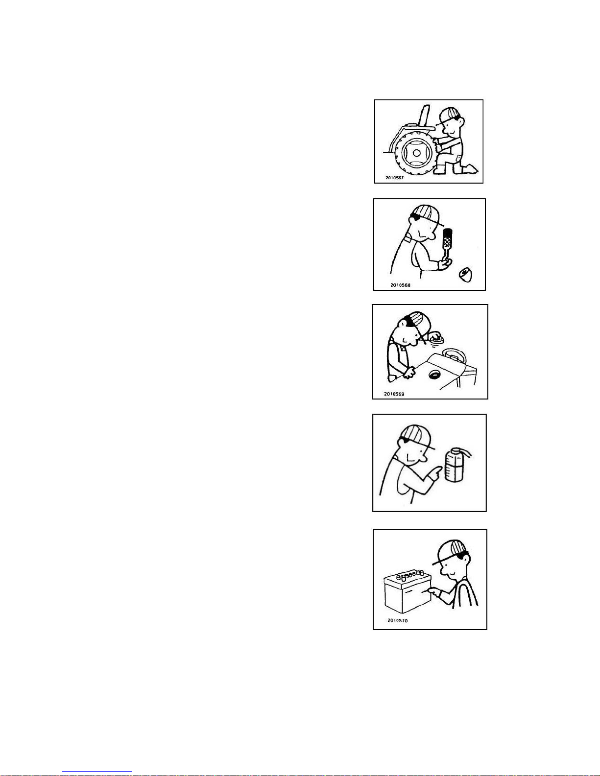
Fluid escaping from very small hole can be almost
invisible. Wear safety goggles for eye protection and
use a piece of cardboard to check for suspected leaks.
Do not use your hands. If injured by escaping fluid, see
a doctor at once. Serious infection or other problems
can develop if proper medical treatment is not
administered immediately.
Disconnect battery ground cable before working on
electrical system or working in any area where you
might come in contact with electrical components.
Disconnect ground cable first and replace at last.
Page 17

16 OPE_EF312T&352T_en.doc
Sulfuric acid in battery electrolyte is poisonous. It can
destroy clothing and burn the skin. Wear eye protection
and rubber gloves when filling battery. If you spill acid
on yourself, flush your skin with water and apply baking
soda or lime to neutralize acid, then get medical
attention immediately. If acid is swallowed, get medical
attention immediately!
STORAGE
Whenever tractor will not be used for a few months, use
following safety precautions:
1) Drain fuel tank.
2) Lower implement.
3) Set parking brake and block wheels.
4) Remove battery and store in cool, dry place, and
keep out of reach of children.
Page 18

17 OPE_EF312T&352T_en.doc
AFTER SALES SERVICES
After sales services
When your tractor is not working normally, check it
referring to the troubleshooting section. You can of
course consult with your service representative.
Whenever you ask service to your service
representative, following information are very helpful to
identify your tractor.
1) Tractor model name and serial number (A).
The serial number is stamped on right side of front
frame (B).
2) Engine model name and serial number (C).
3) Hour-meter (D) reading or estimated hours of
operation.
Turn on key switch to read hour-meter.
4) Operating conditions.
Kind of work and implement used when a problem
is happened.
5) Any other information when a trouble is occurred.
Noise, vibration, function etc.
Availability of spare parts
Maintenance parts or spare parts are available for 10
years after the production of this tractor series has
been discontinued. However, special parts will be
subject to consultation. Yanmar may be able to supply
a particular part after the normal supplying period.
(A) Tractor model name & serial number
(B) Tractor serial number
(C) Engine model name & serial number
Page 19

18 OPE_EF312T&352T_en.doc
TRACTOR OUTLINE
(1)
(2)
(3)
(4)
(5)
(6)
(7)
Head light
Side light
Muffler tail pipe
Fuel refill port
Operator’s seat
Turn signal lamp
Sub-step
(8)
(9)
(10)
(11)
(12)
(13)
Bonnet
Side cover
Front tire
Rear tire
Lower link (3-P)
ROPS (Safety frame, optional equipment)
Page 20

19 OPE_EF312T&352T_en.doc
PARTS N AMES
(1) Main switch
(2) Accelerator lever
(3) Accelerator pedal
(4) Main shift lever
(5) Range shift lever
(6) Reverser lever
(7) PTO shift lever
(8) Brake pedal
(9) Parking brake lever
(10) Clutch pedal
(11) Differential lock lever
(12) Position control lever
(13) Lever stopper
(14) Stop & slow return valve
(15) Head light switch
(16) Horn button
(17) Flasher switch
(18) Side light switch
(19) Seat adjust lever
(20) Brake pedal connector
(21) Front wheel drive lever
(22) Seat belt (option)
Page 21

20 OPE_EF312T&352T_en.doc
Lamps and Indicators
(1) Fuel gauge
(2) Engine coolant temperature gauge
(3) Engine speed meter, RPM
(4) Hour meter
(5) Battery charge pilot lamp
(6) Engine oil pressure pilot lamp
(7) Reverser lever neutral pilot lamp
LABEL LOCATIONS
Keep the safety instructions labels clean and clearly visible for your safety. If any of them are damaged or
missing, replace them with new ones.
Label Model (not for sale)
1. 198122-65730 Caution label 1 pc.
2. 198163-65350 Danger label 1 pc.
3. 198163-65953 Caution label 2 pcs.
4. 198163-65940 Caution label 2 pcs.
5. 1A6150-91251 Fuel label 1pc.
6. 1A6150-93151 PTO cover label 1 pc.
7. 198163-65780 Brake label 1 pc.
Page 22

21 OPE_EF312T&352T_en.doc
CONTROLS
ENGINE
Main switch
The switch is used to turn on and off the engine
OFF
The electric current is shut off.
The engine stops. (The key can be
removed.)
ON
The electric current is on. If the engine is
stopped, the engine oil pressure lamp (6)
and battery charge lamp (5) turn on.
START
Starter motor runs to start the engine, when
range shift lever is at neutral.
Release the key when the engine starts,
and the key returns to the “ON” position
automatically.
(6) Engine oil pressure lamp
(5) Battery charge lamp
Accelerator lever
The accelerator lever (A) is used to increase or
decrease the engine speed or keep the engine at a
constant speed.
(A) Accelerator lever
(SL) Slower engine speed
(FA) Faster engine speed
Accelerator pedal
The accelerator pedal (A) is used to increase or
decrease the engine speed, mainly during travel on the
road. To increase the engine speed, depress the pedal.
(A) Accelerator pedal
Page 23

22 OPE_EF312T&352T_en.doc
TRAVELLING, PTO RE RELATED FUNCTIONS
Main shift lever
The transmission has 4 main gear shifts.
Depress the clutch pedal fully, and move the lever to
desired position.
(A) Main shift lever
IMPORTANT
Be sure the tractor stops whenever shifting. If not, it
may cause damage to transmission gears.
Range shift lever
The transmission has 2 range gear shift aside from 4
main gear shifts.
(B) Range shift lever
2: High Speed range
1: Low speed range
N: Neutral
IMPORTANT
Be sure tractor stops when shifting. Do not change
Range shift lever while moving.
Reverser lever
Reverser lever changes the direction of travel of the
tractor, forward or reverse. Depress the clutch pedal
and stop tractor whenever shift the lever.
Lift up the lever to put it in a required position.
Lever lamp lights in the N position.
(C) Reverser lever
F: Forward
N: Neutral
R: Reverse
IMPORTANT
Be sure tractor stops when shifting. Do not change
Reverser lever while moving.
Page 24

23 OPE_EF312T&352T_en.doc
PTO shift lever
The transmission has 2 PTO speeds. To change the
speed, depress the clutch pedal fully.
(D) PTO shift lever
PTO speed at engine 2,600 rpm
1 572 rpm
2 830 rpm
CAUTION
Strictly maintain the PTO speed as specified by the
implement. Otherwise, the implement or transmission
can be damaged and may cause an injury.
Brake pedal
Tractor has brake pedals for right and left turn
independently and they can be applied separately.
For a sharp turn in the field, depress the brake in which
direction you want to turn. For driving on a road,
never fail to connect both pedals with the connector.
To avoid unnecessary wear of brake discs, do not rest
foot on the brake pedal during operation.
(A) Brake pedals
(B) Brake pedal connector
WARNING
Be sure connect the both brake pedals with the
connector when driving on a load. Tractor may turn
over by one-sided braking in high speed.
Parking brake lever
To apply parking brake;
Connect brake pedals, depress brake pedals and raise
parking brake lever.
To release parking brake;
Depress brake pedals slightly and down parking brake
lever.
(A) Parking brake lever
(B) Brake pedals
(C) Brake connector
(LK) Apply parking brake
(RS) Release parking brake
CAUTION
Be sure connect the both brake pedals with the
connector when applying parking brake. If not, only
left tire is locked and it may not brake tractor
sufficiently.
Page 25

24 OPE_EF312T&352T_en.doc
Clutch pedal
The clutch pedal transmits or cuts engine power to
transmission.
To disengage the clutch, depress clutch pedal and
engine power is disconnected.
To engage the clutch after depressing clutch pedal,
release the pedal slowly and engine power transmits to
transmission.
(A) Clutch pedal
IMPORTANT
Do not rest your foot on the clutch pedal while
operating. It may cause premature wearing of clutch
disc.
Differential gear lock pedal
A differential gear system is equipped on front and rear
axles of this tractor for smooth turning.
Depressing this pedal locks rear axle differential gear
box and rear wheels rotate as if right and left axles are
connected. When one side rear wheel spins and the
other does not rotate, depress the pedal to lock the
differential gear for escaping.
To unlock differential, release the depressed pedal.
IMPORTANT
When differential gear is locked, drive tractor slow
speed and keep going straight. Never steer tractor
while depressing the pedal.
WARNING
Never fail to unlock the differential gear after escaping
from the place. Otherwise, you can not make an
intended turn and an accident may result.
(A) Differential lock pedal
(ON) Lock differential gear
(keep depressing pedal)
(OFF) Release lock (release pedal)
Front wheel drive lever
The lever engages or disengages front wheel drive.
Depress clutch pedal and move the lever when tractor
stops.
(A) Front wheel drive lever
(4WD) ON: Four-wheel drive
(2WD) OFF: Two-wheel drive
IMPORTANT
Be sure tractor stops whenever move the lever.
Disengage front wheel drive when drive with high gear
on a road, hard surface place or towing trailer.
Page 26

25 OPE_EF312T&352T_en.doc
HYDRAULIC SYSTEM
Position control lever
Position control lever controls height of rear hitched an
implement in a desired position.
Lever stopper (B) limits lowering an implement to limit
the working range of the lever, or when traveling on
road.
(A) Position control lever
(B) Lever stopper
(UP) Raise
(DW) Lower
Hydraulic stop and slow return valve
Used to control the lowering speed of implement.
(A) Hydraulic stop and slow return valve
(OP) Open the valve and fast lowering of
implement
(CL) Slow lowering of implement and it stops
hydraulic flow when turned fully.
IMPORTANT
When driving on a road with rear hitched implement, open
the hydraulic stop and slow return valve and fix the hydraulic
control lever in raise position with stopper.
Do not operate the hydraulic control lever when the valve is
fully closed.
Otherwise, it may damage hydraulic parts.
Page 27

26 OPE_EF312T&352T_en.doc
ELECTRIC SYSTEM
Turn signal switch
Turn signal functions when key switch turns on.
Turn the turn signal switch anticlockwise to blink right
side turn signal lamp and turn clockwise to blink left
side lamp.
(A) Turn signal switch
(R) Right lamp blinks.
(L) Left lamp blinks.
Head light switch
Headlights turn on when key switch turns on.
Turn head light switch clockwise to turn on head lights.
(B) Light switch
(OFF) Headlights turn off.
(LB) Headlights turn on with low beam.
(HB) Headlights turn on with high beam.
CAUTION
When there is an oncoming vehicle in night time, be
sure to switch to low beam position. If keep on high
beam, it may cause traffic accident.
Horn button
Horn functions when key switch turns on.
Push horn button to blow horn.
(C) Horn button
Side light switch
Side lights turn on when key switch turns on.
Push side light switch to turn on side lights and push
the switch again to turn off.
(D) Side light switch
Page 28

27 OPE_EF312T&352T_en.doc
INSTRUMENT PANEL
(1) Fuel gauge
(2) Engine coolant temperature gauge
(3) Tachometer
(4) Hour meter
(5) Battery charge pilot lamp
(6) Engine oil pressure pilot lamp
(7) Reverser lever neutral pilot lamp
(1) Fuel gauge
It indicates fuel level remained in fuel tank when key switch turns on.
(2) Engine coolant temperature gauge
It indicates engine coolant temperature.
If this pointer comes to the red zone, reduce engine speed to idling
and wait for cooling down. Find out the cause and call your dealer
if necessary.
(3) Tachometer
Indicates engine speed in revolution per minute (RPM).
It also indicates PTO speed 540rpm.
(4) Hour meter
It shows operating hour of the engine. It shows when key switch is
in “ON” position. Actual working hour may be different from the
meter amount due to engine speed at working.
(5) Battery charge pilot lamp
This lamp lights when the key switch is in “ON” position.
The charge lamp turns off when engine starts. If the lamp does not
turn off at 1500rpm engine speed or higher, see your dealer.
(6) Engine oil pressure pilot lamp
This lamp lights when the key switch is in “ON” position and goes off
when the engine starts. If the lamp does not turn off after engine
starts, stop the engine immediately and check oil level. If oil level is
sufficient, see your dealer.
(7) Reverser lever neutral pilot lamp
The lamp lights when the reverser lever is in “N” position.
Page 29

28 OPE_EF312T&352T_en.doc
OTHERS
Seat adjust lever
It adjusts the operator’s seat position in 5 steps
to-and-fro.
Raise the lever and slide the seat forward or backward
to desired position. Lower the lever to latch the seat.
(A) Seat adjust lever
Opening bonnet
(1) Raise the lever to open bonnet.
(B) Bonnet open lever
(2) Raise the bonnet and hold it with bonnet stay
(C) Bonnet stay
Page 30

29 OPE_EF312T&352T_en.doc
OPERATIONS
1. Pre-operation checks
DANGER
1) Never smoke or use bare lamps/lights during oil
replenishing.
2) Never fill fuel oil while the engine is running or hot.
3) After filling fuel, be sure to cover the fuel tank with
screw-top and wipe off spilled fuel. If not, a fire may
be caused.
4) Check the fuel lines daily. Fuel leaks on a
damaged fuel line.
WARNING
1) Whenever servicing the tractor, place it on a flat and
leveled area. Be sure no traffic neither people
around the tractor. Otherwise, the tractor can
cause an unexpected accident.
2) Whenever servicing under rear hitched implement,
close hydraulic stop and slow return valve (A) and
place lock device or support to the implement.
Otherwise the implement may fall down incidentally
and it can cause injuries.
CAUTION
1) Never fail to stop the engine before checks or
maintenance. If not, you may be trapped in a
rotating part and heavily injured.
2) To check or service the tractor, wait until the engine
and muffler are cooled down. If not, you may got
burned and be injured.
3) Never fail to reinstall covers and parts detached for
service. Otherwise, you may be trapped in the
tractor and heavily injured.
Page 31
30 OPE_EF312T&352T_en.doc
For safety reasons, always check the tractor before
day's work. Remove any abnormalities.
At least check the followings in order:
(1) Abnormalities in previous day
(2) Walk around the tractor to look into:
• Deformed, damaged, worn or lost exposed parts
• Air inflation pressure and wear of tires
• Loosened or lost bolts and nuts of the tire rims and
disks
(3) Check inside the bonnet
• Engine oil level and leaks.
• Fuel oil amount, leak and damages on fuel lines.
• Engine coolant level, leaks and damage on lines.
• Level of battery liquid.
This battery does not need additional replenishment
of battery solution.
It is normal when the color indicated by the
hydrometer on the battery is green. When it is black,
charge the battery again.
Page 32

31 OPE_EF312T&352T_en.doc
• Clogging or dirt in air filter.
• Tension or damage of cooling fan belt.
• Radiator screen, grille and engine room for dust.
• Hydraulic joint and lines for damages and loose
connection.
• Check electrical wirings for wear or damages of
lead sheaths and loose connections.
(4) Check operating system
• Play of brake pedals.
Brake pedals must have reasonable play (A) and
plays of both right and left brake pedals must be
equal. (30-40mm)
Page 33

32 OPE_EF312T&352T_en.doc
• Play of clutch pedal.
Clutch pedal must have reasonable play (A).
(15-25mm)
• Play of steering wheel.
Steering wheel must have reasonable play (A).
(20-50mm)
(5) Check hitched implement
• PTO Drive shaft lock pin must be in groove of PTO
output and input shafts.
• Pins must be inserted in proper positions.
• Loosened bolts and nuts.
• Damaged or worn parts.
• Connection of 3-point linkage.
(6) Start the engine and check:
• Abnormal sound or noise.
• Color and smell of exhaust gas.
• Function of each lamp, gauge and meter
Page 34

33 OPE_EF312T&352T_en.doc
2. Brake-in (initial 50 hours)
The new tractor should be carefully operated for the
first 50 hours. it will surely have an effect on the lifetime
and performance of the tractor throughout the life. Pay
attention to the following points in particular:
(1) Refrain from abrupt start or brake.
(2) Do not operate in higher speed or heavier load
more than necessary. Do not operate with full
load. Avoid from operation such engine speed
comes down by a load or smoke while working.
(3) Start operation after the engine is sufficiently
warmed up.
(4) Slow down on the rough road or slope.
(5) Check the tractor after 50 hours of break-in
period.
3. Before starting
WARNING
1) Before starting the engine, sit on the operator’s seat
and make sure all levers and controls are within the
reach for safe operation. Negligence will cause a
serious injury.
2) Do not run engine in a closed room. Run the
engine in well-ventilated area. If you are forced to
start the engine in a confined room, make sure the
ventilation is proper. Exhaust gas is poisonous and
it can lead to death.
CAUTION
1) Before and after operation, never fail to check and
service the tractor. Particular check will be required
at brake pedals, controls, steering devices and tire
rim fitting bolts. Negligence can cause a heavy
injury or accident to the tractor and the human.
2) Set the parking brake during the warm-up operation.
Otherwise the tractor may abruptly start to run.
Page 35

34 OPE_EF312T&352T_en.doc
4. Start and stop
4-1. Start and stop engine
Start engine
IMPORTANT
1) Do not keep the engine starter motor running for
more than 10 seconds. If the engine does not start,
keep it cool for one minute before retry. Then,
execute steps (3) - (4).
2) Never turn the main switch to start position while
engine is running.
(A) Water separator
(B) Fuel cock (OP) Open
(1) Open the fuel cock (A).
(2) Put the reversser lever and PTO shift lever in
the ”N” position.
(3) Set position control lever in the LOW position.
Make sure that the implement is lowered.
(4) Pull accelerator lever to higher speed position (FA).
(5) Insert key and turn it to “ON” position.
Check pilot lamps on meter panel;
(5) Battery charge pilot lamp is on.
(6) Engine oil pressure pilot lamp is on.
(7) Reverser lever neutral lamp is on.
(6) Turn key switch to “START” position.
(7) As engine starts, immediately release key switch
and it goes back to “ON” position automatically.
When engine starts, battery charge and engine
pressure pilot lamps turn off.
(8) Warm up the engine by running under no-load at
1500 rpm for 5 minutes approximately. Especially if
the temperature is below 0°C, a warm up of at least
10 minutes is required.
(C) Reverser lever
(D) PTO shift lever
(A) Position control lever
(A) Accelerator lever
Page 36

35 OPE_EF312T&352T_en.doc
Stop engine
(1) Push accelerator lever (A) toward (a) to decrease
engine speeds.
(2) Turn key switch to “OFF” position.
(3) See main shift lever, range shift lever, reverser
lever and PTO shift lever are in neutral positions.
IMPORTANT
Sudden stop of hot engine may cause engine
overheating. Prior to stop engine, keep engine
running at 1200 - 1500 rpm for about 2 minutes to cool
down.
(A) Accelerator lever (SL) Slow speed
4-2. Start, gear shifting and stop tractor
Start tractor
(1) Be sure right and left brake pedals are connected
by connector.
(2) Set engine speed about 1500 rpm.
(A) Brake pedals (B) Connector
(3) Move position control lever backward and raise rear
hitched implement.
(A) Position control lever
(UP) Raise rear hitch implement
(4) Depress clutch pedal fully and shift main shift lever
and range shift lever to desired speed.
(A) Main shift lever
(B) Range shift lever
(5) Shift reverser lever to forward or reverse.
(6) Release clutch pedal gradually and tractor starts.
IMPORTANT
1) Never rest your foot on clutch pedal while operating.
It will cause pre-mature wearing of clutch disc.
2) Never fail to lock the parking brake when you leave
the tractor.
3) Look around the tractor to start.
(C) Reverser lever (N) Neutral
(F) Forward (R) Reverse
Page 37

36 OPE_EF312T&352T_en.doc
Gear shifting
(1) Main shift lever
Depress clutch pedal fully and shift lever to desired
speed after tractor stops.
(2) Range shift lever
Depress clutch pedal fully and shift reverser lever
to “N” after tractor stops.
Keep depressing clutch pedal and shift range shift
lever to desired speed.
(3) Reverser lever
Depress clutch pedal fully and shift reverser lever
to (F) or (R) after tractor stops.
IMPORTANT
Never shift main, range and reverser lever while tractor
is moving. If not, it may cause breakage of
transmission inner gear.
Stop tractor
(1) Push accelerator lever forward to reduce speed.
(2) Depress clutch pedal and brake pedals at the same
time.
(3) Shift range shift, reverser and PTO shift levers to “N”
position.
(4) Make sure brake pedals are connected with
connector and apply parking brake (lock brake pedal
with parking brake lever).
(5) Lower rear hitch implement if it is attached.
(6) Turn key switch to “OFF” position and remove the
key.
(A) Parking brake lever (B) Brake pedals
(C) Connector
(LK) Lock (RS) Release
Page 38

37 OPE_EF312T&352T_en.doc
5. Driving on a road
WARNING
1) Make sure that left and right brake pedals are
connected whenever traveling on a road or cross a
farm ridge. One-sided braking effect will roll over
the tractor or result in a sharp turn.
2) Follow the traffic regulations and rules in your place
when running on a road. Strictly one operator only
on tractor.
CAUTION
Remove an implement when traveling on a road. If
not, an accident may result in.
Put the PTO shift lever in “N”.
(1) Connect right and left brake.
(2) Shift PTO shift lever to “N” position.
(3) Open hydraulic stop and slow return valve fully.
(A) Hydraulic stop and slow return valve
(OP) Open valve
(4) Move position control lever up and lock it with
stopper.
CAUTION
Make sure that position control lever is held when
traveling on a road. If not, hand may touch position
control lever incidentally and implement would go
down. It may cause an accident and injury.
(A) Brake pedals (B) Connector
(D) PTO shift lever
(A) Position control lever (B) Stopper
(UP) Raise rear hitched implement
IMPORTANT
1) Adjust the traveling speed with the foot accelerator
pedal.
2) When you turn tractor or change traveling course,
notify others by turning signal lamp.
3) When there is on-coming vehicle in night time, make
headlight be low beam.
4) Disengage front wheel drive except in special case.
Page 39

38 OPE_EF312T&352T_en.doc
6. Driving on a slope
WARNING
1) Select a correct speed before approaching a slope.
Never change shift levers on a slope. Tractor may
coast down unintentionally.
2) Never travel on the slope with reverser lever, main
shift lever or range shift lever set in “N” position.
3) Never depress the clutch pedal on a slope. Tractor
may coast down unintentionally and it may cause an
accident.
4) To start on an up-slope, shift gears to low speed and
engage clutch slowly and carefully. Abrupt start will
jump up the front wheel.
5) Do not park tractor on a slope as much as possible.
If it is required, apply parking brake and put wheel
block to avoid from coasting down.
(1) Select slow speed before going into a slop.
(2) Travel slowly on a slope.
(3) Apply engine brake on a down-slope.
7. Driving in and out of a field
WARNING
1) Be sure to connect left and right brake pedals with
connector. One-sided brake results in causing a
roll over.
2) In case field ridge is high, use a gangplank with
sufficient strength. Lower an implement and go
through ridge in slow speed.
3) If a way to field is steep slop, go up with a reverse
gear.
(A) Ridge
8. Setting adequate speed
8 forward speeds and 8 reverse speeds are available
by the combination of main, range and reverser shift
levers. Select adequate speed for works.
Suggested operation by working speed.
Speed (km/hr)
Shift
Main
shift
Range
shift
EF312T EF352T
Operation
F1 1 1.26 1.32
F2 2 1.83 1.90
F3 3 2.61 2.72
Rotary
F4 4
1
3.94 4.09 Spreader
F5 1 6.58 6.85
F6 2 9.5 9.88
Plow
F7 3 13.60 14.14
F8 4
2
20.49 21.31
Traveling with
the trailer
(At engine speed: 2500rpm/EF312T, 2600rpm/EF352T)
Page 40

39 OPE_EF312T&352T_en.doc
9. Turning in a field
WARNING
Release foot from differential lock pedal to release
differential gear before turning. Otherwise, tractor
cannot turn when it is required and an accident may
result.
Unlatch brake pedal connector in a field.
(1) Reduce the engine speed.
(2) Move position control lever rearward to raise the
implement
(3) Turn steering wheel to desired direction and
depress brake pedal in the same direction of
steering wheel turn at the same time.
ex:
When you turn steering wheel clockwise to turn
right, depress right side brake at the same time.
(A) Differential lock pedal (OFF) Release
(B) Brake pedal
(C) Brake pedal connector
10. Differential gear lock
WARNING
1) Release differential gear lock before making a turn.
Otherwise, tractor can not turn and an accident will
result.
2) Never depress differential lock pedal while traveling
on a road. If you depress the pedal, you could not
steer and may cause an accident and injury.
Differential gear lock system is effective when one side
rear wheel is locked and the other tire slips. When
differential gear is locked, right and left rear axle rotate
as if both axles are connected. It is easier to go out
from muddy and slippery place.
Operation
(1) Lower engine speed.
(2) Depress differential lock pedal.
(3) Release the pedal to unlock differential gear lock.
If it is difficult to unlock the differential system,
depress clutch pedal or step on right and left brake
pedal alternately.
IMPORTANT
1) Never turn steering wheel while differential lock
pedal is depressed.
2) Do not use lowest speed shift gear.
(A) Differential lock pedal
(OFF) Release lock (Release pedal)
(ON) Apply differential lock (Depress pedal)
Page 41

40 OPE_EF312T&352T_en.doc
11. Loading and unloading
DANGER
1) Never steer tractor on loading bridge while loading into
or unloading from cargo truck. Drive tractor in
slowest speed. If not, loss of control can result in
injure or damage the tractor.
2) Never depress clutch pedal on loading bridge.
Tractor may coast down and cause injury.
3) Latch brake pedals. If not, tractor may steer
unintentionally when depress one side brake pedal
only. Tractor may fall down from loading bridge and
may cause injury.
4) Never stand against loading bridge. Be away from
loading work.
WARNING
1) Loading bridge must be of sufficient size, strength
and with anti-slip surface. Length of the loading
bridge must be longer than 4-time of floor deck
height. Fix loading bridge with floor deck of truck.
2) Reverse tractor for loading into truck, go forward for
unloading. Shift gear to slow speed.
3) Tie tractor firmly to truck with a rope of sufficient
strength.
(1) Loading truck preparation
Park the truck on a flat and leveled place where is
wide enough and no traffic expected.
Stop truck engine and apply the parking brake.
Block wheels of the truck.
(2) Loading
Latch right and left brake pedals with connector.
Shift gear levers to slow speed.
Slow down engine speed and reverse tractor to load.
Make sure tractor is aligned with loading bridge.
[If engine stops on loading bridge]
Depress brake pedal immediately and gradually
release brake pedal to go down slowly.
Start engine and load again.
(3) On the floor deck
Apply parking brake of tractor.
Stop tractor engine.
Lower rear hitched implement if any.
Tie tractor with truck
(4) Unloading
Untie tractor.
Start engine and shift gears to low speed.
Raise rear hitched implement if any.
Start tractor forward in slow speed. Do not steer.
(A) Brake pedal (B) Connector
Page 42

41 OPE_EF312T&352T_en.doc
12. Adjusting wheel tread
Adjust the tractor rear wheel tread according to the type
of crops and field preparation.
Apply a wide wheel tread for works on a slope or for a
traction work.
(1) Apply parking brake and put tire stoppers to front
wheels and jack up tractor body to raise rear
wheels.
(2) To adjust the wheel tread, exchange left and right
tires.
IMPORTANT
Front tire tread is not adjustable.
(A) Wheel disc
(a) Standard tread
(b) Max. tread
Tire tread
Tire Size
(ply rate) Standard tread (mm) Wide tread (mm)
Front 7-14 (4) 1000 N.A.
Rear 11.2-24 (4) 1025 1105
13. Hydraulic power take off
Single action cylinder
In case of single action cylinder, remove the
hydraulic outlet plug (A) on right side of control valve,
and connect hydraulic hose from cylinder of
implement.
<Operation>
(1) Set the position control lever in the lower position.
(2) Fasten the hydraulic stop/slow return valve (B) at
fully clockwise position.
(3) Operate the position control lever to move the
implement.
(A) Hydraulic outlet (single action)
(B) Hydraulic stop/slow return valve
(C) Hydraulic outlet (double action, out)
(D) Hydraulic outlet (double action, in)
(E) High pressure pipe
(F) Relief valve
(G) Hydraulic control valve
Double action cylinder
<Connection>
(1) Remove operator’s seat.
(2) Remove the dust cover under the seat.
(3) Remove the high pressure pipe (E).
(4) Connect hydraulic hose to port (C) that the oil goes
to SCV and connect hose to port (D) that oil comes
back from SCV.
(5) Install the dust cover and the seat.
Keep the high pressure pipe for the time when
removing SCV.
Page 43

42 OPE_EF312T&352T_en.doc
14. Using 3-point hitch
3-point rear hitch type is Category 1.
Top link
Adjust length of top link (A) to implement. Loosen
lock nut turn turnbuckle on top link and adjust the
length.
Follow instructions of implements.
(A) Top link (C) Lower link
(B) Lift link (D) Check chain
Lift link and lower link
Set lower link hole and lift link hole according to
implement and work.
Lower link hole Lift link hole Remarks
(1)
Refer to the
instruction of
implement
Standard 3-P
(2) (5) Special 3-P
Never use the combination of hole (2) and hole (3).
Check chain
Check chain adjustment.
(1) For implements such as a plough, harrow and
subsoil plow, adjust check chains so as an
implement could be swung about 5 cm. Make sure
that lower ling does not hit tire.
(2) For implements such as a rotary tiller and mower,
adjust check chains so as implement does not
swing, but not too tight.
IMPORTANT
When an implement is not attached to tractor, tie lower
links to avoid from hitting rear tire while driving.
(C) Check chain
(E)
15. Drawbar hitch
Use Drawbar when towing a trailer.
(A) Drawbar
Page 44

43 OPE_EF312T&352T_en.doc
16. General precautions on attaching and detaching an
implement
WARNING
1) When moving the tractor to attach an implement, never
allow a person between the tractor and the implement.
Always keep the moving speed in the lowest.
2) Attach or detach an implement on a flat and leveled
ground in a safe way. Use lights during nighttime work.
3) When leaving the tractor for attaching or detaching an
implement, never fail to set the parking brake and stop the
engine.
4) Be sure to use the tractor’s original drawbar hitch for
towing work.
5) Attaching an implement results in a considerable longer
overall length. Pay attention to bystanders or
constructions nearby when driving tractor.
6) Never place objects on the tractor or try to use your own
body as counterbalance the tractor. Use only authorized
genuine balance weight or implement.
7) Maximum counter weight on front bracket and rear wheel
is;
Front bracket: 150 kgs
Rear wheel weight: 100kgs for each wheel
8) Add the front weight so that the weight of the front axle
may always become 20% or more of the total weight.
9) Install a cover on PTO shaft when it is not used.
Otherwise, it may cause injury.
10) For safe and correct operations, read the instruction
manual for an implement.
Negligence of safety precautions causes a serious injury
or death.
Page 45

44 OPE_EF312T&352T_en.doc
17. Power steering
This tractor is equipped with hydrostatic powered
steering system.
The hydraulic power assists steering works only when
the engine is running. The steering wheel may
become a little heavier at low engine speeds
WARNING
Whenever the engine is running, steering wheel turns
with very light force. Avoid from abrupt steering or it
may cause uncontrollable steering and may cause
accident or injury.
IMPORTANT
1) When the steering wheel is turned to its end, the
relief valve works and chirp sound comes out. If
relief valve works in a short time, it is not a problem
but long time work of valve may cause trouble in the
hydraulic system.
2) When tractor dose not run, do not turn steering
wheel as much as possible. It may cause damage
on tires or rims.
(A) Safety frame (Optional equipment)
18. Safety frame (ROPS) (Optional equipment)
The safety frame (ROPS, Roll Over Protect Structure)
is designed to protect operator from an accident such
overturn. It is suggested to install safety frame for
safety operation. Please contact Yanmar tractor
dealer nearby.
WARNING
1) Do not modify the safety frame. Safety factor can be
lost.
2) Be sure the safety frame is installed and tightened
firmly. Check loosened bolt and nut and tightened if
loosened.
3) Damaged frame should be replaced as a complete
set. Partial repair may lead loss of safety level and
it may cause serious injury or death.
19. Tightening torque of bolts and nuts
Bolts and nuts being used on this tractor are of grade
“7T” unless otherwise grade is not specified in this
manual.
Tighten torques show on right table.
Bolt size Grade 7T
(mm) (N·m) (kgf-m)
M6 8 - 12 0.8 - 1.2
M8 23 - 30 2.3 - 3.0
M10 44 - 59 4.5 - 6.0
M12 78 - 98 8.0 - 10.0
M14 118 - 147 12.0 - 15.0
M16 167 - 206 17.0 - 21.0
M18 235 - 284 24.0 - 29.0
M20 323 - 402 33.0 - 41.0
Page 46

45 OPE_EF312T&352T_en.doc
OPENING BONNET AND SIDE COVER
Bonnet
Opening
(1) Pull up the bonnet lever (A) to release the bonnet
lock.
(2) Lift the bonnet until the bonnet stand (B) is locked.
Make sure the bonnet stand works properly.
(A) Bonnet lever
Closing
(1) Lift the bonnet a little and pull bonnet stand forward.
Lower bonnet a click sound comes.
(2) Make sure the bonnet is locked securely after
closing the bonnet.
(B) Bonnet stand
Side covers
Opening
(1) Open the bonnet.
(2) Pull upper part of side cover sideway and pull up
side cover.
Closing
Follow reverse sequence of opening procedure.
(C) Side cover
Page 47

46 OPE_EF312T&352T_en.doc
AFTER OPERATION
1. After operation
Clean thoroughly the tractor after daily operation to keep it
in good condition for a long time. In particular, clean lower
and front areas before storing it.
Wash the tractor with water and wipe off. Lubricate
moving parts and sliding parts. Apply grease to all grease
nipples especially after working in wet field.
IMPORTANT
Do not splash or spray water on electrical parts. Water can
cause a trouble in the electrical system.
2. Care for long period of storage
WARNING
When tractor is stored for a long time, remove the battery
and main key. Deterioration of electric wire or rat biting
may cause electric leakage and may start a fire.
When storing for a long time, take following procedures.
(1) Turn off all switches and remove the main switch key.
(2) Place the tractor in a well ventilated place and remove
counterbalance weights or other implements.
(3) Coat exposed metallic parts with anti-rusting oils,
engine oils or greases.
(4) Fill up the fuel tank with fuel. Otherwise, moisture will
develop in the tank and cause rust. Close cock of
water separator and fuel filter.
(5) Charge the battery fully. Remove the battery from the
tractor and keep it in a dark and cool place. If the
battery is kept on the tractor, be sure to disconnect the
ground line (negative lead).
(6) Drain coolant from the engine.
IMPORTANT
The battery is subject to self-discharge.
Charge it fully at least once a month.
(A) Coolant drain plug
Page 48

47 OPE_EF312T&352T_en.doc
(7) Depress clutch pedal and latch pedal lock.
CAUTION
If clutch pedal is not locked for storage, clutch disc may
rust and stick to engine flywheel. Tractor may start
unintentionally when start engine and may cause injury.
(A) Clutch pedal
(B) Clutch pedal lock
(8) Put blocks or stands under tractor to take weight off
tires. Protect tires from heat and sunlight.
(9) Inflate the front and rear tires with air to the normal
pressure.
Size, (ply number) kg/cm
2
(kPa)
Front tire 7-14, (4) 1.8 (180)
Rear tire 11.2-24, (4) 1.2 (120)
Page 49

48 OPE_EF312T&352T_en.doc
PERIODICAL SERVICE
WARNING
1) Stop the engine before servicing.
2) Service tractor on a flat and leveled place, free from normal traffic and bystanders.
3) Fix the tractor wheels not to move.
CAUTION
Check periodically fuel lines and power steering hoses for damages, wearing a nd loose connections. If
there is damage, wearing or loose, be sure to see your dealer. Otherwise an accident or injury can result.
Periodic inspection and maintenance in off-season will ensure the preferable conditions of your tractor. To
keep your tractor working in good conditions, ask your service dealer for a regular inspection.
It is recommended to replace fuel pipes, rubber hoses, and electrical wires every two years at least.
1. Check intervals
x: Check required
CHECK ITEMS 50 h 100h 150h 200h 250h 300h 350h 400h 450h 500h 550h 600h
Engine lubrication oil
Replace Replace
Replace
Replace
Replace
Replace
Replace
Engine oil element
Replace
Replace
Replace
Transmission oil
Replace
x x x x
Replace
x x x x x
Replace
Transmission oil filter
Replace
Replace
Replace
Fuel filter
Replace
Replace
Water separator
strainer
Drain Drain Drain Drain Drain Clean Drain Drain Drain Drain Drain Clean
Radiator fin
Clean Clean Clean Clean Clean Clean Clean Clean Clean Clean Clean Clean
Cooling water
(Replace)
Check before every work (Replacing every year)
Front axle oil
Replace
x x x x
Replace
x x x x x
Replace
Air cleaner element
x x x x x x x
Replace
x x x x
Radiator screen Clean before every work
Battery hydrometer
x x x x x x x x x x x x
Fuel piping, connections
x x x x x x x x x x x x
Rubber hoses
(Power steering)
x x x x x x x x x x x x
Radiator hoses Replace hoses every two years
Hydraulic rubber hoses Replace hoses every two years
Fuel pipe, electric wires Replace pipes and wires every t wo years
Electric wiring,
connections
x x x x x x x x x x x x
Grease-up
x x x x x x x x x x x x
Fastening of steering
wheel fix nut
x x x x x x
Important nuts and
bolts
x x x x x x x
Cooling fan belt
x x x x x x x
Engine breather pipe
x x x x x x x x x x x x
Engine crank case
x
Clearance of exhaust
valve
x
Fuel injection valve
x
Generator, start motor
x x x x
Hydraulic system
x x x x
Check at the first 50 operating hours or after first one-year operation.
Page 50

49 OPE_EF312T&352T_en.doc
2. Oil and grease
Oil, Grease Type
Fuel oil
Diesel fuels; grade 1-D or 2-D defined by ASTM Designation
D975 (see the next chart)
Engine oil API grade CD or better grade, SAE #30 or #40
Transmission and
Hydraulic system oil
Yanmar TF-500A Transmission fluid or equivalent
Front axle Gear oil SAE #90
Grease Multipurpose type (suggested with 3-5% molybdenum disulfide)
3. Capacity of oils and water
(Unit: liters)
EF312T EF352T
Fuel oil 28 28
Cooling Radiator 3.7 3.7
water Sub-tank 0.4 0.4
Engine oil 4.7 4.7
Transmission and
hydraulic system oil
25 25
Front axle oil 5.7 5.7
Power steering oil Common uses of transmission oil
All capacities are approximate.
4. Equivalent oil to transmission fluid TF500A
Supplier Brand name
Mobil Mobil Fluid 425
Castrol Agricastrol MP
John Deere J14A, J20B
ESSO Torque Fluid 56
Shell Shell Tellus Oil 32 or 37
*Oil must not be mixed with other brand.
5. Fuel sytem
5-1. Fuel
WARNING
1) Use diesel fuel only.
2) Do not refill when engine is hot.
3) Keep away sparks, flames and cigarettes while
handling fuel.
4) Wipe off spilled fuel.
(1) Choose the correct diesel fuel. Use either Grade
No. 1-D or Grade No. 2-D fuels, as defined by
ASTM Designation D975 for diesel fuels, or its
equivalent in materials and quality.
(2) Fill fuel tank at end of each day’s operation. This
reduces deposit of water in fuel tank.
(3) Proper fuel storage is important. Keep all dirt,
water, and other contaminants out of fuel. Avoid
from storing fuel for long time.
Page 51

50 OPE_EF312T&352T_en.doc
5-2. Refill fuel
DANGER
1) Never smoke or use a bare lamp/light during filling
fuel.
2) After filling fuel, be sure to put the fuel tank cap back
firmly and clean off spelled fuel.
3) Fill fuel after the engine stops and becomes cool. A
fire can result.
Turn key switch to ON position to check fuel
amount in the tank. Fuel gauge shows
amount that fuel remained in the tank.
Refill fuel as required.
(A)
(A) Fuel gauge
(FC) Fuel tank cap
5-3. Drain and cleaning of water separator
Water separator removes water in fuel. When water is
deposited in the bawl of the
separator, drain it.
(A) Water separator
(B) Fuel cock
(C) Strainer
(D) Drain cock
(E) Retaining ring
(a) Open (b) Close
(WS) Water separator
(1) Turn the fuel cock to close position.
(2) Loosen the drain cock on the bottom of the water
separator and drain water. Do not remove drain
cock.
(3) If water is dirty, loosen retaining ring and remove the
bawl. Clean inside of bawl and strainer.
(4) Tighten drain cock or reinstall the removed bawl,
strainer to the original position.
(5) Open fuel cock and see water separator is filled up
with fuel. Crank engine for about 5 – 10 seconds to
bleed the air from the fuel and start engine.
5-4. Replacing fuel filter (Cartridge type)
Replace
Every 300 hours
(1) Apply lubricating oil to the rubber ring of fuel filter.
(2) Install it surely.
IMPORTANT
Use a genuine filter. Engine fuel injector has very
fine hole. If the filtering efficiency is low, it may
cause a trouble in engine.
(FF) Fuel filter
Page 52

51 OPE_EF312T&352T_en.doc
6. Oil and filter
6-1. Engine oil and filter
DANGER
Never refill or add oil while the engine is hot or running.
A fire may occur or you may be burnt.
Check oil level
Pull out the oil gauge (A) and wipe off oil with a clean
cloth. Reinsert and remove it again to see if the oil
level is within the upper and lower marks.
If insufficient, add oil to reach to specified level zone
(c). Never add oil more than upper limit. It may
cause more oil consumption and carbon deposit in
combustion system.
IMPORTANT
1) Park the tractor on a level place, apply parking brake
and stop engine to check oil level. If the tractor is
on an inclined place, oil level is not correct.
2) Check the oil level before engine starts or engine is
cool. Never check oil level immediately after engine
stops. Wait for at least 20 minutes.
3) Never dispose of oil in rivers, field or place that
contaminate nature. Have the oil handled by
professionals.
(A) Dipstick (B) Oil supply port
(A) Dipstick
(a) Upper limit (b) Lower limit
(c) Specified level zone
Replacing oil
Remove drain plug on the bottom of engine crankcase.
Refill new oil through the oil supply port. Select a
proper type of engine oil and replace it periodically.
Model Capacity Type
EF312T 4.7 lit.
EF352T 4.7 lit.
CD or better grade
SAE #30, #40
Replace
First 50hrs and every 100 hrs.
(C) Drain plug
Engine oil filter
Replace
First 50hrs and every 300 hrs or every 2-3 times
of replacing engine oil, which comes earlier.
Replacing engine oil filter
(1) Drain engine oil.
(2) Turn engine oil filter anticlockwise with a filter
wrench.
(3) Apply a little engine oil on the rubber ring on the
bottom of the new filter and install it.
(4) Refill engine oil and run the engine until engine oil
pressure indicator lamp turns off.
(5) Stop engine and wait for about 20 minutes or more
to check the oil level. Add oil if necessary.
(A) Engine oil filter
Page 53

52 OPE_EF312T&352T_en.doc
6-2. Transmission-hydraulic oil and filter
The transmission oil functions as lubricant of
transmission gears, brake discs and hydraulic system
oil as well. The transmission oil quality and filter is
very important to keep good condition of transmission
and hydraulic system.
Check oil level
(1) Check oil level at oil level window on backside of
transmission. Adequate oil level is between a half of
window and the lowest (L).
(2) If the oil is no seen in oil level window, replenish oil.
(A) Oil level window (B) Oil supply port
(L) Adequate oil level
Replacing oil
Remove drain plug and drain oil. When transmission
is warm, draining oil is easier.
Oil Capacity
Model Capacity Replace
EF312T 25 lit.
EF352T 25 lit.
First 50hrs and
every 300 hrs.
Use Yanmar hydraulic-transmission fluid TF-500A or
equivalent. Do not mix oil with other brand.
Equivalent oil
Supplier Brand name
Mobil Mobil Fluid 425
Castrol Agricastrol MP
John Deere J14A, J20B
ESSO Torque Fluid 56
Shell Shell Tellus Oil 32 or 37
IMPORTANT
When you install drain plug, pay attention not to break
screw tread of transmission case. Transmission case
is made of aluminum. Case itself has enough
strength for normal works, but if you put a bolt
improperly, screw tread is sometime broken easily.
To install drain plug, screw the drain plug by hand first
and when most of tread get in, tighten it by a wrench
finally.
(DR) Transmission oil drain plug
Transmission oil filter (Line filter)
Replace
First 50 hours and every 300 hours.
Replacement
(1) Remove drain plug to drain oil.
(2) Turn transmission oil filter anticlockwise with a filter
wrench.
(3) Apply a little transmission oil on the rubber ring on
the bottom of the new filter and install it.
(4) Refill transmission oil and run the engine for a few
minutes
(5) Stop engine and wait for about 20 minutes or more
to check the oil level. Add oil if necessary.
(FL) Transmission oil filter
Page 54

53 OPE_EF312T&352T_en.doc
6-3. Front axle oil
Check
Park the tractor on a level place.
Hold yellow part of dipstick and turn it anti-clockwise to
loosen screw. Pull out dipstick and wipe off oil.
Insert dipstick without screwing, pull it out and check oil
level. Oil level must be between upper and lower
limit.
IMPORTANT
1) Park the tractor on a level place, apply parking brake
and stop engine to check oil level. If the tractor is
on an inclined place, oil level is not correct.
2) Never grip and remove metal part on the top of
dipstick. The metal part is a breather and could be
removed if you pull it up. If you lost the metal part,
water gets into front axle case and it damages inner
parts.
(A) Dipstick
Replacing oil
Drain plugs of front axle case are located on lower part
of front axle gear case, both right and left individually.
Remove both drain plugs to drain oil.
Model Capacity Oil type Replace
EF312T 5.0 lit.
EF352T 5.0 lit.
Gear oil
SAE #90
First 50hrs and
every 300 hrs.
(FDL) Drain plug, left side
(FDR) Drain plug, right side
(A) Dipstick
(a) Upper limit
(b) Lower limit
Page 55

54 OPE_EF312T&352T_en.doc
7. Engine coolant
DANGER
Never open the radiator cap when the engine is hot.
Hot steam and boiled water may blow out and you may
suffer sever burns.
Check
Open the bonnet and check water level in the sub tank
water is between “FULL” and “LOW” marks.
If water is insufficient, add clean water.
(A) Sub-tank (cooling water)
(B) Cooling water supply port
(C) Radiator cap
(U) Upper limit (FULL)
(L) Lower limit (LOW)
Replacing coolant
(1) Remove the coolant drain plug and drain cooling
water. It is easier for draining to open radiator cap.
(2) Clean the inside of radiator with tap water until dust
or rust does not come out.
It is suggested to use radiator detergent. Fill
radiator with water and detergent and run the
engine in idle speed for more than 15 minutes.
Drain the water.
(3) Fill radiator with clean water.
It is recommended to mix anticorrosive. Run the
engine for about 5 minutes in idle speed to mix
water and anticorrosive.
(CD) Coolant drain plug
IMPORTANT
The mixing ratio of anticorrosive varies depend on
manufacturer. Follow the instruction of its
manufacturer.
8. Bleeding fuel lines of air
If the engine stops due to lack of fuel or if the fuel
strainer element or fuel piping has ever been detached
for maintenance purpose, bleed air by the following
procedure:
(1) Fill up fuel tank if engine stop by short of fuel.
(2) See the bawl of water separator is filled with fuel
and fuel cock is open.
(3) Pull accelerator lever backward to the maximum
speed position.
(4) Turn the main switch in the start position and run the
starter motor for 5 - 10 seconds.
IMPORTANT
Never run starter motor more than 10 seconds. It may
cause breakage of starter motor. If you cannot start
engine within 10 seconds, restart engine after 2-5
minutes.
(A) Accelerator lever
(FA) Increase speed (higher speed)
Page 56

55 OPE_EF312T&352T_en.doc
9. Radiator screen
Radiator screen catches dust getting into radiator fins.
If the screen is covered by dust, it causes engine over
heat.
Check the screen before every work.
Open the bonnet and check radiator screen.
Pull up sub-tank and air intake pipe. Pull up radiator
screen and clean it.
Be sure sub-tank and air intake pipe are returned to
the positions properly.
(A) Radiator screen
(B) Sub-tank (D) Air intake pipe
10. Cleaning air cleaner elements (dual element)
The air cleaner serves to keep the engine in favorable
conditions by removing dust in air and preventing the
cylinder liner and piston ring from premature wearing.
For operation in a dusty environment, clean the air
cleaner element every 50 hours or earlier and replace it
every 400 hours or earlier.
For operation in a normal condition, clean it every 100
hours and replace it every 1000 hours or every year.
Lift the front end part of air cleaner.
(2) Open the cap and take out the outer element. Tap
dust out of the outer element. If much dust on the
element, blow air from inside of the element. Be
careful not to damage the fins.
(3) Return the outer element, close the cap as “TOP”
mark upward and clip firmly.
(4) Push down the front end part of the air cleaner to the
original position.
(A) Air cleaner
IMPORTANT
1) Do not take out the inner element. It avoid from
getting dust into the engine air intake part. It is not
necessary to replace inner element as long as no
damage on it or too much dirty.
2) Never operate engine with inner element only.
Inner element can not work as outer element.
(C)
(B)
(B) Outer element
(C) Inner element
Page 57

56 OPE_EF312T&352T_en.doc
11. Checking battery
CAUTION
1) Battery electrolyte evaporates and hydrogen gas
comes out. Hydrogen gas is flammable. Never
smoke while handling battery. Keep all sparks and
open flames away from battery. If hydrogen gas
catches fire, battery will explode and cause serious
injury.
2) Use flashlight to check battery electrolyte level.
Never use open flame.
3) Make sure to disconnect battery ground cable before
servicing any part of electrical system.
4) To remove battery, disconnect the ground (negative)
cable first and disconnect positive cable. To install
battery, connect the positive cable first and connect
ground (negative) cable.
WARNING
Sulfuric acid in battery electrolyte is injurious and
poisonous. It is strong enough to burn skin, eat holes
in clothing, and cause blindness if it is splashed into
eyes.
To avoid the hazards:
(1) Filling battery in a well-ventilated area.
(2) Wearing eye protection and rubber gloves.
(3) Avoiding breathing fumes when electrolyte is added.
(4) Avoiding spilling or dripping electrolyte.
If you spill acid on yourself:
(1) Flush your skin with water.
(2) Apply baking soda or lime to help neutralize the
acid.
(3) Flush your eyes with clean water for 10 - 15 minutes
and get medical attention immediately.
(4) If acid is swallowed, get medical attention
immediately.
Battery of EF312T/EF352T
Page 58

57 OPE_EF312T&352T_en.doc
11-1. Check battery
This tractor is equipped with a calcium battery, sealed
type at the factory. It is not required to refill battery
electrolyte.
(A) Negative (ground) terminal
(B) Positive terminal
(C) Hydrometer
(D) Breather
(E) Fixing nuts
Check battery charge conditions with hydrometer.
Color in the hydrometer shows conditions.
Color Charge status Actions required
Green Normal Usable
Black Discharged Recharge.
Transparent
Low electrolyte
level
End of service life.
Replace the battery.
IMPORTANT
1) Make sure the tractor is level and check the
hydrometer.
2) Check color right down on the hydrometer.
3) If the indicated color is transparent or pale green,
lightly tap the battery to make sure of no bubbles and
check it again.
11-2. Removing and installing battery
Remove
(1) Open the bonnet.
(2) Disconnect the negative (ground) cable from the
battery and disconnect the positive cable.
(3) Loosen fixing nuts and remove the battery.
Installation
(1) Connect positive cable and negative cable.
(2) Tighten fixing nut.
(A) Negative (ground) cable
(B) Positive cable
(E) Fixing nuts
IMPORTANT
1) When connecting the battery cables, wipe oil away
from the terminal contacts. After connecting cables,
apply grease to the terminals.
2) Be sure to attach the rubber boots for the positive
terminal of the battery.
3) When replacing the battery, be sure to use the
genuine battery or equivalent specified in the right
table
4) For environmental protection and recycle of
resources, return the old battery fallowing the
regulation of your place.
Battery type of EF312T/EF352T
Model Specified battery Parts code No.
EF312T
EF352T
80D26R or
NX110-5MF
1A7000-51540
Voltage 12 Volts
Capacity 5HR 55 AH
Charging rate 11 Amperes
Page 59

58 OPE_EF312T&352T_en.doc
11-3. Charging battery
DANGER
Never charge the battery with quick charger or fast charger. Internal
pressure of the battery increases and the battery may explode. It may
cause serious injury.
IMPORTANT
Charge the battery only when the color of hydrometer is black.
Charge the battery as following procedures.
(1) Remove the battery.
(2) Connect the battery positive cable to the positive side of the charger,
the battery negative cable to the negative side of the charger.
(3) Charge the battery at approximately 3 amperes for 8 to 10 hours.
When the hydrometer color becomes green, charge is completed.
(4) Install the battery to the tractor.
12. Checking pipes and hoses
Check fuel pipes, hydraulic power steering pipes and
radiator hoses for leak and loose connections. It is
recommended to replace such parts every two years.
DANGER
Aged or damaged pipes leak fuel or hydraulic oil and it
may cause a fire. If a leak is found, replace the pipe
with new one.
(A) Fuel pipe
(B) Radiator hose
(C) Radiator hose
13. Checking electrical wires
Open the bonnet and take off side covers. Check
damage, loose connection. Check them every 50
hours or have them periodically checked every year.
WARNING
1) A damaged electric wire causes short circuit and it
may cause a fire. Check before starting day’s work.
2) Clear dust, weeds or rice straws away wires and
connections before starting works. Those objects
cause a short circuit and it may cause a fire.
(A) Electric wires
Page 60

59 OPE_EF312T&352T_en.doc
14. Greasing
Before starting day's work, check the greasing
condition at each point.
Apply grease normally every 50 hours.
Apply grease after every day’s work when you work in
wet paddy field.
(1) Tie rod end
Tie rod end Left Right
(2) Power steering rod
Power steering rod Left Right
(3) Center pin support
Center pin support Front Rear
(4) Brake pedal shaft
Brake pedal shaft Left Right
(5) Lift arm shaft
Lift arm shaft Left & Right
Page 61

60 OPE_EF312T&352T_en.doc
15. Adjusting brake
WARNING
1) Check free play of brake pedal before every work.
If brake is not work properly, accident may occur.
2) Unequal free play of left and right brake can cause
abrupt turn and it may cause injury. Keep the same
amount of play. Otherwise, an accident can result.
Disconnect brake pedals if latched.
Push down right and left brake pedals one by one and
check free play of each pedal to be 30-40mm. Both
pedals must have the same free play.
Adjustment
(1) Loosen lock nut of brake rod. Turn brake rod to
adjust pedal free play to 30-40 mm. The free play
of one pedal must equal to the other.
(2) Make sure to tighten lock nut.
IMPORTANT
Make sure parking brake can be applied firmly.
(A) Brake pedal
(BL) Brake rod, left (BR) Brake rod, right
(Ln) Lock nut
16. Adjusting clutch pedal
Push down the clutch pedal and check the free play.
The specified free play of clutch pedal is 15-25 mm.
IMPORTANT
Do not rest foot on clutch pedal while operating. It
may cause premature wearing of clutch disc.
(A) Clutch pedal
Adjustment
(1) Loosen lock nut. Turn the turnbuckle to adjust free
play to 15-25 mm.
(2) Tighten lock nut firmly.
IMPORTANT
1) When free play is less than 15 mm;
Engagement of engine flywheel and clutch disc is
not enough and it will cause premature wearing of
clutch disc.
2) When free play is more than 25 mm;
Disengagement of engine flywheel and clutch disc is
not enough and it will cause noise when sifting
gears. It also may cause damage on gears.
(Cr) Clutch rod
(Ln) Lock nut (Tb) Turnbuckle
Page 62

61 OPE_EF312T&352T_en.doc
17. Checking steering wheel
WARNING
Check free play of steering wheel. The normal free
play is 20-50 mm.
This tractor is equipped with hydrostatic power steering
and it causes less wearing of steering system.
When free play is more than normal, check wearing of
tie rod ends. The wearing of tie rod end causes more
free play on steering wheel.
(A) Steering wheel free play.
Measure the free play on wheel circle.
(Tr) Tie rod (Re) Tie rod end
18. Adjusting fan belt
CAUTION
Stop the engine and wait until the engine is sufficiently
cooled down. Otherwise, you may be burned.
Check
Press the fan belt with a finger at the midpoint and see
the belt deflections.
The specified deflection is 10 -15 mm.
Adjustment
(1)
Open the bonnet and pull upper part of the left side
cover and remove it.
(2) Loosen generator bolt, belt adjuster bolt, and
generator nut.
(3) Move generator to stretch the belt tight. Tighten
generator bolt and see deflection. If the deflection is
10 - 15 mm, tighten generator bolt, generator nut
and belt adjuster bolt.
IMPORTANT
When tractor is new, fan belt stretched in a short time.
Check belt deflection frequently.
(A) Fan belt (B) Generator bolt.
(C) Generator
(B) Generator bolt (C) Generator
(D) Belt adjuster (E) Belt adjuster bolt
(F) Generator nut
Page 63

62 OPE_EF312T&352T_en.doc
19. Checking and adjusting toe-in
When a tractor runs, front wheels intend to go outward
due to camber angle. The toe-in gives a counter force
against outward force to run straight.
If the toe-in is not adjusted appropriately, steering may
not be stable.
Check
(1) Put front wheel to be straight.
(2) Measure the distance between the center of right
tire and left tire in front side (b).
(3) Measure the distance between the center of right
tire and left tire in rear side (a).
(4) See the difference.
The amount of (a) must be bigger than (b).
Specified toe-in: a - b = 4 - 8 mm
F: Forward
R: Rearward
a: distance between the center of tires, rear
b: distance between the center of tires, front
Adjustment
(1) Lift up front wheel slightly. It is not necessary that
front tires are floating.
(2) Loosen the lock nuts, left and right.
(3) Turn tie rod to adjust the front wheel tread and
measure front side and rear side of wheel tread.
(4) When the toe-in is specified amount, tighten the
lock nuts.
(Tr) Tie rod (Ln) Lock nut, right and left
20. Replacing fuse
20-1. Fuse box
The fuse box is located at left side of dashboard nearby
clutch rod.
Remove fuse box caps and check fuses. Replace the
blown fuse with new one.
CAUTION
Be sure to use a fuse of specified capacity. If a
bigger capacity fuse is replaced, it may burn electric
wire and cause a fire. Never use electric wire or iron
wire etc. as a fuse.
(A) Fuse box
(1) 5 A Combination meter
(2) 5 A Turn signal
(3) 10 A Tail lamp
(4) 10 A Meter lamps, gauges
(5) 15 A Head light, horn, side lamp
(6) 5 A Reverser neutral switch
(7) 10 A Fuel stop start solenoid
Spare: 15 A, 10 A, 5 A
Page 64

63 OPE_EF312T&352T_en.doc
20-2. Slow blow fuse
Slow blow fuses are located on left side of the engine.
The slow blow fuse protects main electric circuit that
requires heavy current.
CAUTION
Be sure to use a genuine slow blow fuse. Never use
electric wire or iron wire etc. as a fuse. It may cause
a fire.
(A) Slow blow fuse
There are 3 slow blow fuses.
1) Alternator circuit
2) Main circuit
3) Start circuit
21. Checking tire and wheel
Check dairy damages, wear and air inflation of tires.
Check dairy looseness of tire hub bolts and nuts.
Check dairy crack and bent of wheel and rim.
WARNING
Never operate the tractor when a tire hub bolt or nut is
loosened. It may cause injury if a tire is taken off while
operating.
(A): Excessive
(B): Standard
(C): Insufficient
Checking tires
Adjust the inflation pressures of the front and rear tires
to the standard pressure. Also check for any crack or
faults on the tires.
Standard inflation pressure of tire
Tire size
(ply)
Pressure
Kpa (kgf/cm2)
Front 7-14 (4) 180 (1.8)
Rear 11.2-24 (4) 120 (1.2)
EF312T, EF352T
Hub bolt and nut tightening torque
Tighten hub bolts and nuts with specified tightening
torque. A rear wheel is fixed with 4 bolts and 2 nuts.
IMPORTANT
Do not tighten more than specified torque. It may
break screw tread and fixing would be insufficient.
When a hub bolt or nut loosen frequently, check screw
tread and replace if necessary.
118 to 147Nm
Front wheel
(12 to 15kgf-m)
177 to 196Nm
Tightening torque
Rear wheel
(18 to 20kgf-m)
EF312T, EF352T
Page 65

64 OPE_EF312T&352T_en.doc
22. Color of exhaust gas
The color of exhaust gas is black just after engine
starts and it is gray or no color during operation.
Black: Incomplete combustion due to dense fuel.
White: Engine oil is burning.
Normal exhaust may look white at
extremely low temperature.
If exhaust gas is black or white without a load on the
tractor, consult with your service dealer.
Page 66

65 OPE_EF312T&352T_en.doc
TROUBLESHOOTING
If abnormal operations are found, stop the engine and found a problem by referring to the following table.
1. Engine
PROBLEM CAUSE REMEDY
No fuel or improper fuel
Fill fuel.
Drain wrong fuel and fill proper fuel.
Water, dirt, or air in fuel system Drain, flush & bleed fuel system.
Clogged fuel filter Clean or replace fuel filter.
Fuel shut-off valve closed Open fuel shut-off valve.
Accelerator lever not pulled Pull throttle lever.
Starter motor
runs.
Engine oil too heavy Use oil of proper viscosity.
Reverser lever is not set to “N”. Set the lever to neutral.
PTO shift lever is not set to “N”. Set the lever to neutral.
Low voltage Charge battery.
Engine hard
to start or
not start
Starter motor
doesn’t run.
Slow blow fuse blown Replace slow blow fuse.
Vent in fuel tank cap clogged Clean cap in solvent and blow dry.
Fuel filter clogged Clean or replace fuel filter.
Water, dirt, or air in fuel system Drain, flush & bleed fuel system.
Dirty or faulty injection nozzles See your YANMAR dealer.
Improper type of fuel Use proper fuel.
Engine solenoid linkage out of
adjustment
See your YANMAR dealer.
Engine runs irregularly or
stalls frequently
Insufficient oil Add oil
Low coolant temperature Remove and check glow plug.
Engine overheating See "Engine overheats".
Idle speed too slow Check idle speed.
Engine knocks
Improper type of fuel Use proper fuel.
Engine overloaded Reduce load or shift to lower gear.
Air cleaner element clogged Clean air cleaner element.
Clogged fuel filter Clean or replace fuel filter.
Improper type of fuel Use proper fuel.
Engine overheating See "Engine overheats".
Improper ballast Adjust ballast to load.
Hydraulic stop valve closed Open stop valve.
Lack of engine power
Improper implement mounted
Check required horsepower for
implement.
Page 67

66 OPE_EF312T&352T_en.doc
1. Engine (continued)
PROBLEM CAUSE REMEDY
Engine overloaded Reduce load or shift to lower gear.
Low coolant level
Fill coolant and check cooling system for
loose connections or leak.
Loose or defective fan belt Adjust fan belt and replace if needed
Radiator screen or fins clogged Clean radiator screen or fins.
Cooling system needs flushing Flush cooling system.
Defective thermostat Remove and check thermostat.
Engine overheats
Defective temperature gauge or
sender
See your YANMAR dealer.
Oil viscosity is too light Use proper viscosity oil.
High oil consumption
Oil leaks
Check for leaks in lines, seals, drain plug
and around gaskets.
Improper type of fuel Use proper fuel.
Engine emits white
smoke
Low engine temperature
Warm up engine to normal operating
temperature.
Improper type of fuel Use proper fuel.
Engine overloaded Reduce load or shift to lower gear.
Engine emits black or
gray smoke
Air cleaner clogged Clean or replace air cleaner element.
Improper type of fuel Use proper fuel.
Engine overloaded Reduce load or shift to lower gear.
Air cleaner clogged Clean or replace air cleaner and element.
Crankcase breather clogged Clean breather pipe.
Radiator screen or fins clogged Clean radiator screen or fins.
Improper implement mounted
Check required horsepower for
implement.
Tire pressure too low. Inflate tires to proper pressure.
High fuel consumption
Clutch slipping. Adjust clutch free travel or replace disk.
Unusual noise Defective component parts See your YANMAR dealer.
2. Electrical system
PROBLEM CAUSE REMEDY
Loose or corroded connections Clean and tighten connections.
Battery service life is ending
Check electrolyte level and specific
gravity and replace if necessary.
Loose or defective fan belt Adjust belt tension or replace belt.
Battery not charged
Excessive engine idling Allow engine to idle when necessary.
Low engine speed Increase speed.
Defective battery
Check electrolyte level and specific
gravity and replace if necessary.
Charging indicator lamp
lights during operation
Loose or defective fan belt Adjust belt tension or replace belt.
Engine oil pressure indicator
lamp lights
Low oil Add oil.
Page 68

67 OPE_EF312T&352T_en.doc
3. Hydraulic system
PROBLEM CAUSE REMEDY
Low oil level Fill system with proper oil.
Hydraulic stop valve closed Open stop valve.
Excessive load on hitch Reduce load.
Hydraulic oil too cold Allow oil to warm up.
Hydraulic oil filter clogged Replace filter.
Defective hydraulic pump or control
valve
See your YANMAR dealer.
Implement not raises
Oil leaks Check oil leaks.
Hydraulic stop valve closed Open stop valve.
Hitch drops slowly or does
not drop
Slow return valve set slow Open valve and adjust drop speed.
Slow return valve set fast Close valve and adjust drop speed.
System drops too fast
Improper oil Use oil with proper viscosity.
Incorrect oil viscosity Drain and fill oil with proper viscosity.
Low oil level Fill to proper oil level.
Dirty oil Drain and fill clean oil.
Keeping steering wheel at the end Release steering wheel.
System overheating
Control lever not returned to neutral
position when using implement
Return lever to neutral position.
4. Power train
PROBLEM CAUSE REMEDY
Transmission oil level low Add proper type of oil.
Abnormal noise
Worn or broken gears/bearings See your YANMAR dealer.
Brakes adjusted unevenly Adjust brake pedal free travel.
Right and left tires inflated unevenly Inflate tires to proper pressure.
Tractor is pulled to one side
Implement improperly adjusted See implement operator's manual
Page 69

68 OPE_EF312T&352T_en.doc
SPECIFICATIONS
Model
EF312T(4WD) EF352T(4WD)
Make Yanmar
Model 3TNV84 3TNV88
Type Direct injection, Water cooled, diesel
SAE Gross (hp) 30.1 34.5
Output
SAE Gross (ps) 30.5 35.0
Rated RPM (rpm) 2500 2600
No. of cylinders 3
Displacement (cc) 1,496 cc 1,642 cc
Engine
Fuel tank (lit.) 28
Overall length (mm) 2850
Overall width (mm) 1325
Overall height (steering wheel) (mm) 1365
Front (mm) 1000
Tread
Rear (mm) 1025, 1105
Wheelbase (mm) 1600
Dimension
Ground clearance (mm) 350
Weight (kg) 920 920
Front 7 - 14 7 - 14
Tire size
Rear 11.2 - 24 11.2 - 24
Steering Hydrostatic power steering
Brake Wet multi-disc type
Clutch Dry single
No. of shifting gears
8 forward and 8 reverse
(constant & sliding mesh)
Reverser Synchro-mesh
Forward (km/hr) 1.29 – 22.5 1.34 – 23.4
Transmission
Travel speed
Reverse (km/hr) 1.26 - 22.1 1.31 – 23.0
Turning radius (m) 2.2
Gear 1 540 rpm 560 rpm
PTO
Gear 2 785 rpm 815 rpm
Type Position control
Hitch 3-point hitch
Category Category 1
Max. lifting capacity (at lower link end) (kg) 1000
Hydraulic
system
Hydraulic pump capacity (lit./min) 22 23
Note:
All technical data, measurement and weight are approximate, and the manufacturer has the right to make
alteration without prior notice.
Page 70

OPE_EF312T&352T_en.doc
1-32, Chayamachi, Kita-ku, OSAKA 530-8321, JAPAN
TeL : 06-6376-6336~8 Fax : 06-6373-9474
Revised April 2007
PRINTED IN JAPAN
 Loading...