

Yanmar 3JH4E, 4JH4E, 4JH4-TE, 4JH4-HTE Service Manual


Publication No. 0BJH4-G00101
History of Revision
Manual Name Service Manual for Marine Diesel Engine
Engine Model: 3JH4E / 4JH4E / 4JH4-TE / 4JH4-HTE
Number
of
revision
New edition February 2004
R1 Jan.
Date of
revision
Aug.
2006
2007
Reason for
correction
Adding
4JH4-TE /
4JH4-HTE.
Outline of correction
• 4JH4-TE and 4JH4-HTE added.
• Manual code "M9961-03E091"
was changed to "0BJH4-G00100".
• 3 / 4JH4E alternator standard. Page 4, 5, 304,
• Correction the procedure of
measurement and adjustment of
intake and exhaust valves.
Correction item
No (page)
308.
Page 63 - 67. YMI Business
Corrected by
Marine Business
Development
Dept.
Development
Department
Printed in Japan


FOREWORD
This service manual has been compiled for engineers engaged in sales, service, inspection and
maintenance. Accordingly, descriptions of the construction and functions of the engine are emphasized
in this manual, while items, which should already be common knowledge, are omitted.
One characteristic of a marine diesel engine is that its performance in a vessel is governed by the
applicability of the vessel's hull construction and its steering system.
Engine installation, fitting out and propeller selection have a substantial effect on the performance of the
engine and the vessel. Moreover, when the engine runs unevenly or when trouble occurs, it is essential
to check a wide range of operating conditions - such as installation to the full and suitability of the ship's
piping and propeller - and not just the engine itself. To get maximum performance from this engine, you
should completely understand its functions, construction and capabilities, as well as proper use and
servicing.
Use this manual as a handy reference in daily inspection and maintenance, and as a text for engineering
guidance.
Model 3JH4E and 4JH4-TE have been used for the illustrations in this service manual, but they apply to
other models in the JH4 series engines.
California
Proposition 65 Warning
Diesel engine exhaust and some of its
constituents are known to the State of
California to cause cancer, birth defects, and other reproductive harm.
(only for 3JH4E)
California
Proposition 65 Warning
Battery posts, terminals, and related accessories contain lead and lead compounds, chemicals known to the State
of California to cause cancer and reproductive harm.
Wash hands, after handling.
(only for 3JH4E)
©2006 YANMAR CO., LTD
All rights reserved. This manual may not be
reproduced or copied, in whole or in part,
without the written permission of YANMAR
CO., LTD.


CONTENTS
1. General ............................................................................................................................ 1
1.1 Exterior views ......................................................................................................... 1
1.2 Specifications ..........................................................................................................4
1.3 Fuel oil, lubricating oil and coolant ........................................................................ 10
1.3.1 Fuel oil....................................................................................................... 10
1.3.2 Lubricating oil ............................................................................................ 12
1.3.3 Coolant...................................................................................................... 13
1.4 Engine outline ....................................................................................................... 14
1.5 Piping diagrams .................................................................................................... 33
1.6 Exhaust Gas Emission Regulation in U.S.A. only ................................................. 46
1.6.1 Engines under 37kw: 3JH4E..................................................................... 46
1.6.2 Engines of 37kW or more: 4JH4-TE and 4JH4-HTE................................. 49
2. Inspection and adjustment .............................................................................................52
2.1 Periodic maintenance schedule ............................................................................ 52
2.2 Periodic inspection and maintenance procedure .................................................. 54
2.2.1 Check before starting ................................................................................ 54
2.2.2 Inspection after initial 50 hours or one month operation ........................... 60
2.2.3 Inspection every 50 hours or monthly ....................................................... 69
2.2.4 Inspection every 250 hours or one year.................................................... 74
2.2.5 Inspection every two years........................................................................ 84
2.2.6 Inspection every 1,000 hours or four years............................................... 84
2.3 Adjusting the no-load maximum or minimum speed ............................................. 94
2.4 Sensor inspection ................................................................................................. 95
2.4.1 Oil pressure switch.................................................................................... 95
2.4.2 Thermo switch........................................................................................... 95
2.5 Thermostat inspection ..........................................................................................96
2.6 Adjusting operation ............................................................................................... 97
2.6.1 Preliminary precautions............................................................................. 97
2.6.2 Adjusting operation procedure .................................................................. 97
2.6.3 Check points and precautions during running........................................... 98
2.7 Long storage .........................................................................................................99
3. Troubleshooting ...........................................................................................................100
3.1 Preparation before troubleshooting ....................................................................100

3.2 Quick reference chart for troubleshooting ........................................................... 101
3.3 Troubleshooting (Concerning engine and fuel injection equipment) ................... 117
3.4 Troubleshooting by measuring compression pressure ....................................... 120
4. Disassembly and reassembly ......................................................................................122
4.1 Disassembly and reassembly precautions ......................................................... 122
4.2 Disassembly and reassembly tools .................................................................... 123
4.2.1 General hand tools.................................................................................. 123
4.2.2 Special hand tools................................................................................... 125
4.2.3 Measuring instruments............................................................................ 131
4.2.4 Other material ......................................................................................... 136
4.3 Disassembly and reassembly ............................................................................. 138
4.3.1 Disassembly............................................................................................ 138
4.3.2 Reassembly ............................................................................................ 156
5. Inspection and servicing of basic engine parts ............................................................175
5.1 Cylinder block ..................................................................................................... 175
5.1.1 Inspection of parts................................................................................... 175
5.1.2 Cleaning of oil holes................................................................................ 175
5.1.3 Color check procedure ............................................................................ 176
5.1.4 Replacement of cup plugs....................................................................... 177
5.1.5 Cylinder bore measurement.................................................................... 178
5.2 Cylinder head ......................................................................................................179
5.2.1 Inspecting the cylinder head ................................................................... 181
5.2.2 Valve seat correction procedure ............................................................. 182
5.2.3 Intake/exhaust valves, valve guides........................................................ 184
5.2.4 Valve springs........................................................................................... 188
5.2.5 Assembling the cylinder head ................................................................. 190
5.2.6 Measuring top clearance......................................................................... 191
5.2.7 Intake and exhaust rocker arms.............................................................. 192
5.2.8 Adjustment of valve clearance ................................................................ 193
5.3 Piston and piston pins .........................................................................................194
5.3.1 Piston ...................................................................................................... 195
5.3.2 Piston pin ................................................................................................ 196
5.3.3 Piston rings ............................................................................................. 197
5.4 Connecting rod ...................................................................................................200

5.4.1 Inspecting the connection rod ................................................................. 201
5.4.2 Crank pin metal ....................................................................................... 202
5.4.3 Piston pin bushing................................................................................... 204
5.5 Crankshaft and main bearing ..............................................................................205
5.5.1 Crankshaft............................................................................................... 205
5.5.2 Main bearing ........................................................................................... 208
5.6 Camshaft and tappets .........................................................................................209
5.6.1 Camshaft................................................................................................. 209
5.6.2 Tappets ................................................................................................... 211
5.7 Timing gear ......................................................................................................... 212
5.7.1 Inspecting the gears................................................................................ 212
5.7.2 Gear timing marks................................................................................... 212
5.8 Flywheel and housing .........................................................................................213
5.8.1 Position of top dead center and fuel injection timing............................... 214
5.8.2 Damper disc ............................................................................................ 214
6. Fuel Injection equipment .............................................................................................215
6.1 Fuel Injection pump/governor for 3JH4E and 4JH4E ......................................... 215
6.1.1 Fuel system diagram............................................................................... 215
6.1.2 Fuel injection pump service data............................................................. 216
6.1.3 Fuel injection pump structure .................................................................. 219
6.1.4 Removing a fuel injection pump .............................................................. 220
6.1.5 Installing a fuel injection pump ................................................................ 221
6.1.6 Adjusting fuel injection timing.................................................................. 221
6.1.7 Troubleshooting of fuel injection pump ................................................... 221
6.1.8 Tools ....................................................................................................... 222
6.2 Fuel feed pump ...................................................................................................224
6.2.1 Construction of fuel feed pump ............................................................... 224
6.2.2 Fuel feed pump specifications................................................................. 224
6.2.3 Disassembly and reassembly of fuel feed pump..................................... 225
6.2.4 Fuel feed pump inspection ...................................................................... 226
6.3 Fuel injection pump/ governor for 4JH4-TE and 4JH4-HTE ............................... 227
6.3.1 Fuel system diagram............................................................................... 227
6.3.2 Fuel injection pump structure .................................................................. 228
6.3.3 Fuel injection pump service data............................................................. 233
6.3.4 Removing a fuel injection pump .............................................................. 234

6.3.5 Installing a fuel injection pump ................................................................ 235
6.3.6 Adjusting fuel injection timing.................................................................. 235
6.3.7 Troubleshooting of fuel injection pump ................................................... 236
6.4 Fuel injection nozzle ........................................................................................... 237
6.5 Fuel Filter ............................................................................................................239
6.5.1 Fuel filter for 3JH4E and 4JH4E.............................................................. 239
6.5.2 Fuel filter for 4JH4-TE and 4JH4-HTE .................................................... 240
6.6 Fuel tank ............................................................................................................. 241
7. Intake and exhaust system .......................................................................................... 242
7.1 Intake system ......................................................................................................242
7.1.1 3JH4E and 4JH4E................................................................................... 242
7.1.2 4JH4-TE .................................................................................................. 242
7.1.3 4JH4-HTE ............................................................................................... 242
7.1.4 Breather system (A reductor to intake air system of blowby gas) ........... 243
7.1.5 Diaphragm assy inspection (only for 3JH4E and 4JH4E) ....................... 244
7.2 Exhaust system ..................................................................................................245
7.2.1 Exhaust system for 3JH4E and 4JH4E ................................................... 245
7.2.2 Exhaust system for 4JH4-TE and 4JH4-HTE.......................................... 246
7.2.3 Mixing elbow inspection .......................................................................... 246
7.3 Turbocharger ......................................................................................................247
8. Lubrication system .......................................................................................................252
8.1 Lubrication system ..............................................................................................252
8.2 Lube oil pump ..................................................................................................... 253
8.2.1 Lube oil pump construction ..................................................................... 253
8.2.2 Specifications of lube oil pump................................................................ 253
8.2.3 Lube oil pump disassembly and reassembly .......................................... 254
8.2.4 Lube oil pump inspection ........................................................................ 255
8.2.5 Oil pressure control valve construction ................................................... 256
8.3 Lube oil filter .......................................................................................................257
8.3.1 Lube oil filter construction ....................................................................... 257
8.3.2 Lube oil filter replacement ....................................................................... 257
8.4 Lube oil cooler ....................................................................................................258
8.4.1 Lube oil cooler construction .................................................................... 258
8.4.2 Inspecting the lube oil cooler................................................................... 258

8.5 Piston cooling oil nozzle ..................................................................................... 259
8.6 Rotary waste oil pump (Optional) ....................................................................... 260
9. Coolant system ............................................................................................................261
9.1 Coolant system ................................................................................................... 261
9.2 Seawater pump ...................................................................................................263
9.2.1 Specifications of seawater pump ............................................................ 264
9.2.2 Seawater pump disassembly .................................................................. 265
9.2.3 Seawater pump Inspection...................................................................... 265
9.2.4 Seawater pump reassembly.................................................................... 266
9.3 Fresh water pump ............................................................................................... 267
9.3.1 Fresh water pump construction............................................................... 267
9.3.2 Specifications of fresh water pump ......................................................... 268
9.3.3 Fresh water pump disassembly .............................................................. 268
9.3.4 Fresh water pump inspection .................................................................. 269
9.4 Heat exchanger ..................................................................................................271
9.4.1 Heat exchanger construction .................................................................. 271
9.4.2 Specifications of heat exchanger ............................................................ 271
9.4.3 Disassembly and reassembly of the heat exchanger.............................. 271
9.4.4 Heat exchanger inspection...................................................................... 272
9.5 Pressure cap and coolant recovery tank ............................................................ 273
9.5.1 Pressure cap construction....................................................................... 273
9.5.2 Pressure cap pressure control ................................................................ 273
9.5.3 Pressure cap inspection.......................................................................... 273
9.5.4 Replacing filler neck ................................................................................ 274
9.5.5 Function of the coolant recovery tank ..................................................... 275
9.5.6 Specifications of coolant recovery tank................................................... 275
9.5.7 Mounting the coolant recovery tank ........................................................ 276
9.5.8 Precautions on usage of the coolant recovery tank ................................ 276
9.6 Thermostat ..........................................................................................................277
9.6.1 Functioning of thermostat........................................................................ 277
9.6.2 Thermostat construction.......................................................................... 277
9.6.3 Characteristics of thermostat .................................................................. 277
9.6.4 Thermostat inspection............................................................................. 277
9.6.5 Testing the thermostat ............................................................................ 277
9.7 Bilge pump and bilge strainer (Optional) ............................................................ 278

9.7.1 Introduction ............................................................................................. 278
9.7.2 Description .............................................................................................. 279
9.7.3 Cautions .................................................................................................. 280
9.7.4 Assembly procedure ............................................................................... 281
9.7.5 Cautions for assembling.......................................................................... 283
9.7.6 Troubleshooting ...................................................................................... 285
10. Reduction and reversing gear ...................................................................................286
10.1 Specifications of 3JH4E marine gears .............................................................. 286
10.2 Specifications of 4JH4E and marine gears ....................................................... 287
10.3 Specifications of 4JH4-TE and 4JH4-HTE marine gears .................................. 288
11. Remote control system (Optional) ............................................................................. 290
11.1 Remote control system ..................................................................................... 290
11.1.1 Construction of remote control system.................................................. 290
11.1.2 Remote control device components...................................................... 290
11.2 Remote control installation ...............................................................................292
11.3 Remote control inspection ................................................................................ 295
11.4 Remote control adjustment ...............................................................................296
12. Electrical system ........................................................................................................297
12.1 Electrical system ...............................................................................................297
12.1.1 Wiring diagram ...................................................................................... 298
12.2 Battery .............................................................................................................. 300
12.3 Starting motor ...................................................................................................301
12.3.1 Specifications ........................................................................................ 301
12.3.2 Characteristics ...................................................................................... 301
12.3.3 Structure................................................................................................ 302
12.3.4 Wiring diameter of a starting motor ....................................................... 303
12.4 Alternator 12V/60A (Optional) ...........................................................................304
12.4.1 Specifications ........................................................................................ 304
12.4.2 Structure................................................................................................ 305
12.4.3 Wiring diagram ...................................................................................... 306
12.4.4 Standard output characteristics............................................................. 306
12.4.5 Inspection.............................................................................................. 307
12.5 Alternator 12V/80A (Standard) .........................................................................308
12.5.1 Specifications ........................................................................................ 308

12.5.2 Structure................................................................................................ 309
12.5.3 Wiring diagram ...................................................................................... 310
12.5.4 Standard output characteristics............................................................. 310
12.6 Instrument panel ............................................................................................... 311
12.6.1 B-type instrument panel (Selectable optional) ...................................... 311
12.6.2 C-type instrument panel (Selectable optional) ...................................... 311
12.7 Warning devices ...............................................................................................312
12.7.1 Oil pressure alarm................................................................................. 312
12.7.2 Sender unit for lube oil pressure gauge ................................................ 313
12.7.3 Coolant temperature alarm ................................................................... 314
12.7.4 Sender unit for the coolant temperature gauge..................................... 314
12.8 Air heater (Optional) .........................................................................................315
12.9 Electric engine stopping device ........................................................................316
13. Service standards ...................................................................................................... 317
13.1 Engine tuning .................................................................................................... 317
13.2 Engine body ...................................................................................................... 319
13.2.1 Cylinder head ........................................................................................ 319
13.2.2 Camshaft and gear train........................................................................ 321
13.2.3 Cylinder block........................................................................................ 322
13.3 Lubricating oil system (Trochoid pump) ............................................................ 326
14. Tightening torque for bolts and nuts ..........................................................................327
14.1 Main bolt and nut .............................................................................................. 327
14.2 Standard bolts and nuts (without lube oil) .........................................................327


FOR SAFETY
1. SAFETY LABELS
• Most accidents are caused by negligence of basic safety rules and precautions. For accident
prevention, it is important to avoid such causes before development to accidents.
Please read this manual carefully before starting repair or maintenance to fully understand safety
precautions and appropriate inspection and maintenance procedures.
Attempting at a repair or maintenance job without sufficient knowledge may cause an unexpected
accident.
• It is impossible to cover every possible danger in repair or maintenance in the manual. Sufficient
consideration for safety is required in addition to the matters marked . Especially for
safety precautions in a repair or maintenance job not described in this manual, receive instructions
from a knowledgeable leader.
• Safety marks used in this manual and their meanings are as follows:
DANGER-indicates an imminent hazardous situation which, if
not avoided, WILL result in death or serious injury.
WARNING-indicates a potentially hazardous situation which, if
not avoided, COULD result in death or serious injury.
CAUTION-indicates a potentially hazardous situation which, if
not avoided, may result in minor or moderate injury.
• NOTICE - indicates that if not observed, the product performance or quality may not be
guaranteed.

2. Safety Precautions
(1) SERVICE AREA
• Sufficient Ventilation
Inhalation of exhaust fumes and dust particles may be hazardous to ones
health. Running engines welding, sanding, painting, and polishing tasks
should be only done in well ventilated areas.
• Safe / Adequate Work Area
The service area should be clean, spacious, level and free from holes in
the floor, to prevent "slip" or "trip and fall" type accidents.
• Clean, orderly arranged place
No dust, mud, oil or parts should be left on the floor surface.
[Failure to Observe]
An unexpected accident may be caused.
• Bright, Safely Illuminated Area
The work area should be well lit or illuminated in a safe manner. For work
in enclosed or dark areas, a "drop cord" should be utilized. The drop cord
must have a wire cage to prevent bulb breakage and possible ignition of
flammable substances.
• Safety Equipment
Fire extinguisher(s), first aid kit and eye wash / shower station should be
close at hand (or easily accessible) in case of an emergency.

(2) WORK - WEAR (GARMENTS)
• Safe Work Clothing
Appropriate safety wear (gloves, special shoes / boots, eye / ear
protection, head gear, harness', clothing, etc.) should be used / worn to
match the task at hand. Avoid wearing jewelry, unbuttoned cuffs, ties or
Well fitting !!
loose fitting clothes around moving machinery. A serious accident may
occur if caught in moving / rotating machinery.
(3) TOOLS
• Appropriate Lifting / Holding
When lifting an engine, use only a lifting device (crane, jack, etc.) with
sufficient lifting capacity. Do not overload the device. Use only a chain,
cable, or lifting strap as an attaching device. Do not use rope, serious
injury may result.
To hold or support an engine, secure the engine to a support stand, test
bed or test cart designed to carry the weight of the engine. Do not
overload this device, serious injury may result.
Never run an engine without being properly secured to an engine support
stand, test bed or test cart, serious injury may result.
• Appropriate Tools
Always use tools that are designed for the task at hand. Incorrect usage
of tools may result in damage to the engine and or serious personal injury.
(4) GENUINE PARTS and MATERIALS
• Genuine Parts
Always use genuine YANMAR parts or YANMAR recommended parts and
goods. Damage to the engine, shortened engine life and or personal
injury may result.

(5) FASTENER TORQUE
• Torquing Fasteners
Always follow the torque values and procedures as designated in the
service manual. Incorrect values, procedures and or tools may cause
damage to the engine and or personal injury.
(6) Electrical
• Short Circuits
Always disconnect the (-) Negative battery cable before working on the
electrical system. An accidental "short circuit" may cause damage, fire
and or personal injury. Remember to connect the (-) Negative battery
cable (back onto the battery) LAST
• Charging Batteries
Charging wet celled batteries produces hydrogen gas. Hydrogen gas is
extremely explosive. Keep sparks, open flame and any other form of
ignition away. Explosion may occur causing severe personal injury.
• Battery Electrolyte
Batteries contain sulfuric acid. Do NOT allow it to come in contact with
clothing, skin and or eyes, severe burns will result.
(7) WASTE MANAGEMENT
Observe the following instructions with regard to hazardous waste
disposal. Negligence of these will have a serious impact on environmental
pollution concerns.
1) Waste fluids such as lube oil, fuel and coolant shall be carefully put
into separate sealed containers and disposed of properly.
2) Do NOT dispose of waste materials irresponsibly by dumping them
into the sewer, overland or into natural waterways.
3) Waste materials such as oil, fuel, coolant, solvents, filter elements and
batteries, must be disposed of properly according to local ordinances.
Consult the local authorities or reclamation facility.

(8) FURTHER PRECAUTIONS
• Fueling / Refueling
Keep sparks, open flames or any other form of ignition (match, cigarette,
etc.) away when fueling / refueling the unit. Fire and or an explosion may
result.
• Hot Surfaces.
Do NOT touch the engine (or any of its components) during running or
shortly after shutting it down. Scalding / serious burns may result. Allow
the engine to cool down before attempting to approach the unit.
• Rotating Parts
Be careful around moving / rotating parts. Loose clothing, jewelry, ties or
tools may become entangled causing damage to the engine and or
severe personal injury.
• Preventing burns from scalding
1) Never open the filler cap shortly after shutting the engine down.
Steam and hot water will spurt out and seriously burn you. Allow the
engine to cool down before attempt to open the filler cap.
2) Securely tighten the filler cap after checking the coolant.
Steam can spurt out during engine running, if tightening loose.
• Safety Label Check
Pay attention to the product safety label.
A safety label (caution plate) is affixed on the product for calling special
attention to safety.If it is missing or illegible, always affix a new one.

3. Precautions for Service Work
(1) Precautions for Safety
Read the safety precautions given at the beginning of this manual carefully and always mind safety in
work.
(2) Preparation for Service Work
Preparation is necessary for accurate, efficient service work. Check the customer ledger file for the
history of the engine.
• Preceding service date
• Period / operation hours after preceding service
• Problems and actions in preceding service
• Replacement parts expected to be required for service
• Recording form / check sheet required for service
(3) Preparation before Disassembly
• Prepare general tools, special service tools, measuring instruments, oil, grease, non-reusable parts,
and parts expected to be required for replacement.
• When disassembling complicated portions, put match-marks and other marks at places not
adversely affecting the function for easy reassembly.
(4) Precautions in Disassembly
• Each time a parts is removed, check the part installed state, deformation, damage, roughening,
surface defect, etc.
• Arrange the removed parts orderly with clear distinction between those to be replaced and those to
be used again.
• Parts to be used again shall be washed and cleaned sufficiently.
• Select especially clean locations and use clean tools for disassembly of hydraulic units such as the
fuel injection pump.
(5) Precautions for Inspection and Measurement
Inspect and measure parts to be used again as required to determine whether they are reusable or not.
(6) Precautions for Reassembly
• Reassemble correct parts in correct order according to the specified standards (tightening torques,
and adjustment standards). Apply oil important bolts and nuts before tightening when specified.
• Always use genuine parts for replacement.
• Always use new oil seals, O-rings, packing and cotter pins.
• Apply sealant to packing depending on the place where they are used. Apply of grease to sliding
contact portions, and apply grease to oil seal lips.
(7) Precautions for Adjustment and Check
Use measuring instruments for adjustment to the specified service standards.

1. General
1.1 Exterior views
(1) 3JH4E
• Operation side
1. General
(1)
(2)
(3)
(1) Intake silencer (5) Lube oil filter (9) Fuel filter
(2) Shift lever (6) Fuel feed pump (10) Dipstick
(3) Marine gear (7) Oil filter cap (11) Intake manifold
(4) Oil cooler (8) Fuel injection pump
(11)
(10)
(9)
(8)
(7)
(6)
(5)
(4)
010297-01X
• Non operation side
(1)
(2)
(3)
(1) Coolant filler cap (4) Starter motor (7) Alternator
(2) Engine name plate
(on the rocker arm cover)
(3) Seawater pump (6) Exhaust manifold
(5) Exhaust mixing elbow (8) Coolant tank/Heat exchanger
(8)
(7)
(6)
(5)
(4)
010298-01X
<Note> This illustration shows the 3JH4E with Yanmar marine gear (Model:KM35P).
1

1. General
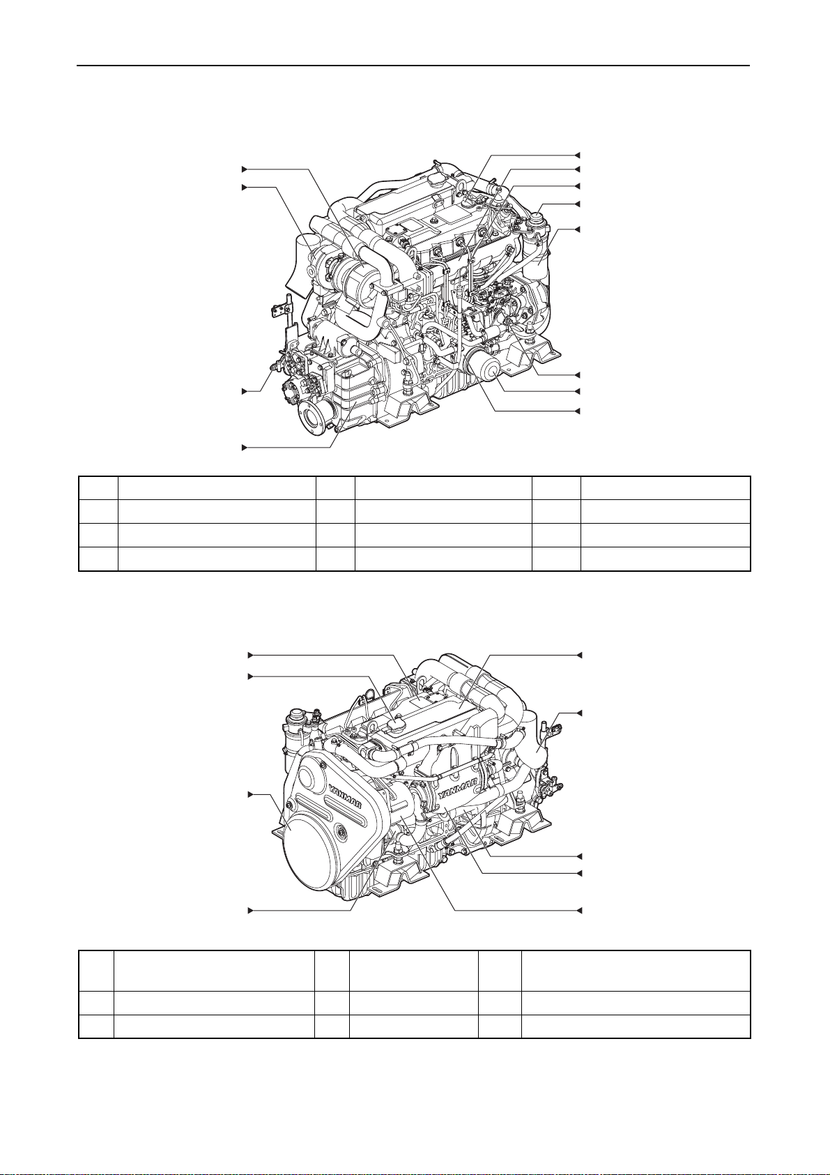
(2) 4JH4-TE
• Operation side
(1)
(2)
(3)
(12)
(11)
(10)
(9)
(8)
(7)
(6)
(5)
(4)
008831-01X
(1) Intake silencer (5) Lube oil cooler (9) Fuel priming pump
(2) Turbocharger (6) Lube oil filter (10) Dipstick
(3) Shift lever (7) Fuel injection pump (11) Intake manifold
(4) Marine gear (KMH4A) (8) Fuel filter (12) Oil filler cap
• Non operation side
(1)
(8)
(2)
(7)
(3)
(6)
(4)
(1) Engine name plate
(4) Seawater pump (7) Exhaust mixing elbow
(5)
008832-01X
(on the rocker arm cover)
(2) Coolant filler cap (5) Alternator (8) Coolant tank/Heat exchanger
(3) Belt cover (6) Starter motor
<Note> This illustration shows the 4JH4-TE with Yanmar marine gear (Model: KMH4A).
2
(3) 4JH4-HTE
• Operation side
(1)
(2)
(3)
1. General
(12)
(11)
(10)
(9)
(8)
(7)
(6)
(5)
(4)
008392-01X
(1) Intake silencer (5) Lube oil cooler (9) Fuel priming pump
(2) Turbocharger (6) Lube oil filter (10) Dipstick
(3) Shift lever (7) Fuel injection pump (11) Intake manifold
(4) Marine gear (KMH4A) (8) Fuel filter (12) Oil filler cap
• Non operation side
(1)
(9)
(2)
(8)
(3)
(7)
(6)
008393-01X
(5)
(1) Engine name plate
(4)
(4) Seawater pump (7) Starter motor
(on the rocker arm cover)
(2) Coolant filler cap (5) Alternator (8) Exhaust mixing elbow
(3) Belt cover (6) Intercooler (9) Coolant tank/Heat exchanger
<Note> This illustration shows the 4JH4-HTE with Yanmar marine gear (Model: KMH4A).
3

1. General
1.2 Specifications
(1) 3JH4E series (3JH4E, 3JH4BE, 3JH4CE, 3JH4ME)
Official engine model name unit 3JH4E
Company internal model name
Marine gear model - KM35P KM35A SD50 Bobtail
Use - Pleasure use
Type - Vertical water cooled 4 cycle diesel engine
Combustion system - Direct injection
Air charging - Naturally aspirated
Number of cylinders - 3
Bore x stroke mm(inch) 88 x 90 (3.46 x 3.54)
Displacement L 1 .642
Continuous
power
Fuel stop
power
Installation - Flexible mounting
Fuel injection timing
Fuel injection opening
pressure
Main power take off - At flywheel side
Direction of
rotation
Cooling system - Fresh water cooling with heat exchanger
Lubrication system - Complete enclosed forced lubrication
Coolant capacity (fresh)
Lubricating
oil capacity
(engine)
Starting
system
Engine
dimension
Flywheel major dimension mm(inch) Ø300 x 66 (11.8 x 2.6)
Engine dry mass
(include marine gear)
Output at
crankshaft /
Engine speed
Output at
crankshaft /
Engine speed
Output at
propeller shaft /
Engine speed
Crankshaft - Counter-clockwise viewed from stern
Propeller shaft
(Ahead)
Rake angle deg.
Total (Note 4)
Oil pan only
Effective (Note 5)
Type - Electric
Starting motor
AC generator V-A 12V-80A (12V-60A optional)
Overall length
Overall width 539 (21.2) 539 (21.2) 539 (21.2) 539 (21.2)
Overall height 623 (24.5) 623 (24.5) 623 (24.5) 623 (24.5)
- 3JH4E 3JH4BE 3JH4CE 3JH4ME
kW(HP)/min
kW(HP)/min
kW(HP)/min
deg b.T.D.C.
(kgf/cm
L(quart) Engine:4.5 (4.8), Coolant recovery tank : 0.8 (0.8)
L(quart)
mm(inch)
-1
-1
-1
MPa
2
)
- Clockwise viewed from stern - -
V-k W
kg 185 186
(at Fuel temp. 25°C)
(at Fuel temp. 40°C)
at rake angle 8 deg
5.0±0.3 (5.3±0.3) 5.5±0.3 (5.8±0.3) 5.5±0.3 (5.8±0.3) 5.5±0.3 (5.8±0.3)
4.5±0.3 (4.8±0.3) 5.0±0.3 (5.3±0.3) 5.0±0.3 (5.3±0.3) 5.0±0.3 (5.3±0.3)
1.1 (1.2) 1.2 (1.3) 1.2 (1.3) 1.2 (1.3)
777 (30.6) 776 (30.6) 700 (27.6) 700 (27.6)
29.4(40.0) / 3000 (at Fuel temp. 25°C)
28.7(39.0) / 3000 (at Fuel temp. 40°C)
28.0(38.1) / 3000
27.4(37.3) / 3000
26.7(36.3) / 2907
--
FID 12±1 (FIC-Air 13±1)
21.6±0.5 (220±5)
at rake angle 0 deg
DC 12V-1.4 kW
213
(engine:173)
173
(Note)
1. Rating condition: ISO 3046-1, ISO 8665
• Fuel temperature 25°C at the inlet of the fuel injection pump. (ISO 3046-1, 1995)
• Fuel temperature 40°C at the inlet of the fuel injection pump. (ISO 8665)
2. 1HP (metric horse power) ≒ 0.7355 kW
3. Fuel condition: Density at 15°C = 0.842
4. The "Total" oil quantity includes: Oil in oil pan and oil in channels, coolers and filter.
5. The effective amount of oil shows the difference in maximum scale of the dipstick and minimum scale.
4

1. General
(2) 4JH4E series (4JH4E, 4JH4FE, 4JH4BE, 4JH4B4E, 4JH4CE, 4JH4ME)
Official engine model name unit 4JH4E
Company internal model name
Marine gear model
Use
Type
Combustion system
Air charging
Number of cylinders
Bore x stroke mm(inch) 88 x 90 (3.46 x 3.54)
Displacement L 2.190
Continuous
power
Output at
crankshaft/
Engine speed
Output at
crankshaft/
Fuel stop
power
Engine speed
Output at
propeller shaft /
Engine speed
Installation - Flexible mounting
Fuel injection timing
Fuel injection opening pressure
Main power take off
Direction of
rotation
Crankshaft
Propeller shaft
(Ahead)
Cooling system
Lubrication system
Coolant capacity (fresh) L (quart) Engine 6.0(6.3), Coolant recovery tank: 0.8(0.8)
Rake angle deg. at rake angle 8 deg at rake angle 0 deg
Lubricating
oil capacity
(engine)
Total (Note 4)
Oil pan only 4.5±0.3(4.8±0.3) 5.0±0.3(5.3±0.3)
Effective (Note 5) 1.2(1.3) 1.4(1.5)
Type - Electric
Starting
system
Starting motor V-kW DC 12V-1.4 kW
AC generator V-A 12V-80A (12V-60A optional)
Overall length
Engine
dimension
Overall width 560(22.0) 560(22.0) 560(22.0) 560(22.0) 560(22.0)
Overall height 618(24.3) 618(24.3) 618(24.3) 618(24.3) 618(24.3)
Flywheel major dimension mm(inch) Ø300 x 66(11.8 x 2.6)
Engine dry mass
(include marine gear)
- 4JH4E 4JH4FE 4JH4BE 4JH4B4E 4JH4CE 4JH4ME
- KM35P ZF30M KM35A2 KM4A1 SD50 Bobtail
-
-
-
-
-
kW(HP)/min
kW(HP)/min
kW(HP)/min
-1
-1
-1
deg b.T.D.C.
Vertical water cooled 4 cycle diesel engine
40.5(55.1) / 3000 (at Fuel temp. 25 °C)
39.6(53.8) / 3000 (at Fuel temp. 40 °C)
38.5(52.3) / 3000 (at Fuel temp. 25 °C)
37.6(51.1) / 3000 (at Fuel temp. 40 °C)
Pleasure use
Direct injection
Naturally aspirated
4
36.8(50.0) / 2907
FID 13± 1 (FIC-Air 14± 1)
MPa 21.6±0.5
-
-
-
Clockwise viewed from stern -
-
-
Counter-clockwise viewed from stern
Fresh water cooling with heat exchanger
Complete enclosed forced lubrication
At flywheel side
5.0±0.3(5.3±0.3) 5.5±0.3(5.8±0.3)
L (quart)
871(34.3) 950(37.4) 864(34.0) 922(36.3) 795(31.3)
mm(inch)
kg
212 228 213 228
240
(engine:200)
-
200
(Note)
1. Rating condition: ISO 3046-1, ISO 8665
• Fuel temperature 25°C at the inlet of the fuel injection pump. (ISO 3046-1, 1995)
• Fuel temperature 40°C at the inlet of the fuel injection pump. (ISO 8665)
2. 1HP (metric horse power) ≒ 0.7355 kW
3. Fuel condition: Density at 15°C = 0.842
4. The "Total" oil quantity includes: Oil in oil pan and oil in channels, coolers and filter.
5. The effective amount of oil shows the difference in maximum scale of the dipstick and minimum scale.
5

1. General
Marine gear and sail drive for 3JH4E and 4JH4E
Marine gear
or sail drive
Model - KM35P
KM35A
(down angle: 7)
KM35A2
(down angle: 7)
Type - Mechanical cone clutch
Reduction ratio
(Forward/Reverse)
Propeller speed
(Forward/Reverse)*
- 2.36/3.16 2.61/3.16 2.33/3.04 2.64/3.04 2.33/3.06 2.64/3.06
-1
min
1231/921 1114/921 1246/955 1103/955 1246/950 1103/950
Lubrication system - Splash
Lubricating oil
capacity (total)
Lubricating oil
capacity (effect)
L
(quart)
0.5 (0.5) 0.65 (0.69) 0.65 (0.69)
0.05 (0.05) 0.15 (0.16) 0.15 (0.16)
Cooling system - Air cooling by fan on flywheel
Mass kg 12 13 13
Model - ZF30M kM4A1
(coupled at
boat builder)
Type -
Reduction ratio
(Forward/Reverse)
- 2.15/2.64 2.70/2.64
Mechanical multi
plate clutch
1.47/
1.47
Mechanical cone clutch
2.14/
2.14
2.63/
2.63
3.30/
3.30
SD50
2.32
Marine gear
or sail drive
Propeller speed
(Forward/Reverse)*
min
-1
1353/1103 1078/1103
Lubrication system - Splash Centrifugal pump Oil bath
Lubricating oil
capacity (total)
Lubricating oil
L
(quart)
capacity (effect)
Cooling system - Seawater cooling -
Mass kg 27.5 27.5 40
* At continuous power engine speed 2907 min
1983/
1983
1360/
1360
1106/
1106
882/
882
1.1 (1.2) 1.3 (1.4) 2.1(2.2)
0.2 (0.2) 0.2 (0.2) -
-1
1253
6

1. General
(3) 4JH4-TE series (4JH4-TFE, 4JH4-TBE, 4JH4-THE, 4JH4-TIE, 4JH4-TCE, 4JH4M-TE)
Official engine model name unit 4JH4-TE
Company internal model name
Marine gear model - ZF30M KM4A2 KMH4A ZF25A SD50-4T Bobtail
Use - Pleasure use
Type - Vertical water cooled 4 cycle diesel engine
Combustion system - Direct injection
Air charging - Turbocharged
Number of cylinders - 4
Bore x stroke mm (inch) 84 x 90 (3.31 x 3.54)
Displacement L 1.995
Continuous
power
Output at
crankshaft/
Engine speed
Output at
crankshaft/
Fuel stop
power
Engine speed
Output at
propeller shaft/
Engine speed
Installation - Flexible mounting
Fuel injection timing
Fuel injection opening
pressure
Main power take off - At flywheel side
Crankshaft - Counter-clockwise viewed from stern
Direction of
rotation
Propeller shaft
(Ahead)
Cooling system - Fresh water cooling with heat exchanger
Lubrication system - Complete enclosed forced lubrication
Coolant capacity (fresh) L (quart) Engine: 7.2(7.6), Coolant recovery tank: 0.8(0.8)
Rake angle deg. 7 deg 0 deg 7 or 0 deg
Lubricating
Total (Note 4)
oil capacity
(engine)
Oil pan only
Effective (Note 5)
Starting
system
Engine
dimension
Type - Electric
Starting motor V-kW DC 12V-1.4 kW
AC generator V-A 12V-80A (12V-60A optional)
Overall length
Overall width 616(24.3)
Overall height 659(25.9)
Flywheel major dimension mm (inch) D339 x 66 (13.3 x 2.6)
Engine dry mass
(include marine gear)
-
4JH4-TFE 4JH4-TBE 4JH4-THE 4JH4-TIE 4JH4-TCE 4JH4M-TE
kW (HP)/min
kW (HP)/min
kW (HP)/min
deg b.T.D.C.
-1
-1
-1
53.0(72.1) / 3200 (at Fuel temp. 40 °C)
55.2(75.1) / 3200 (at Fuel temp. 40 °C)
Plunger lift at Top Dead Center: 1.26±0.01mm (when W-C.S.D. is released)
FIT (at plunger lift 1.00mm with W-C.S.D. released): 2.55±1
50.2(68.3) / 3101
MPa 21.6±0.5
-
L (quart)
Clockwise
viewed
from stern
5.7±0.3
(6.0±0.3)
5.2±0.3
(5.5±0.3)
Clockwise or counter-clockwise
(Bi-rotation)
6.9±0.3
(7.3±0.3)
6.4±0.3
(6.8±0.3)
2.4(2.5)
923(36.3) 903(35.6) 933(36.7)
mm (inch)
kg 235 237 238 237
1017(40.0)
-
-
Refer
to left
Refer
to left
782(30.8) 782(30.8)
249
(engine 207)
207
(Note)
1. Rating condition: ISO 8665
• Fuel temperature 40°C at the inlet of the fuel injection pump. (ISO 8665)
2. 1HP (metric horse power) ≒ 0.7355 kW
3. Fuel condition: Density at 15°C = 0.842
4. The "Total" oil quantity includes: Oil in oil pan and oil in channels, coolers and filter.
5. The effective amount of oil shows the difference in maximum scale of the dipstick and minimum scale.
7

1. General
(4) 4JH4-HTE series (4JH4-HTFE, 4JH4-HTBE, 4JH4-HTHE, 4JH4-HTIE, 4JH4M-HTE)
Official engine model name unit 4JH4-HTE
Company internal model name
Marine gear model - ZF30M KM4A2 KMH4A ZF25A Bobtail
Use - Pleasure use
Type - Vertical water cooled 4 cycle diesel engine
Combustion system - Direct injection
Air charging - Turbocharged with intercooler
Number of cylinders - 4
Bore x stroke
Displacement L 1.995
Continuous
power
Output at
crankshaft/
Engine speed
Output at
crankshaft/
Fuel stop
power
Engine speed
Output at
propeller shaft/
Engine speed
Installation - Flexible mounting
Fuel injection timing
Fuel injection opening
pressure
Main power take off - At flywheel side
Crankshaft - Counter-clockwise viewed from stern
Direction of
rotation
Propeller shaft
(Ahead)
Cooling system - Fresh water cooling with heat exchanger
Lubrication system - Complete enclosed forced lubrication
Cooling water capacity (fresh) L (quart) Engine: 7.2(7.6), Coolant recovery tank: 0.8(0.8)
Rake angle deg. 7 deg 0 deg 7 or 0 deg
Lubricating
Total (Note 4)
oil capacity
(engine)
Oil pan only
Effective (Note 5)
Starting
system
Engine
dimension
Type - Electric
Starting motor V-kW DC 12V - 1.4 kW
AC generator V-A 12V-80A (12V-60A optional)
Overall length
Overall width 616(24.3)
Overall height 659(25.9)
Flywheel major dimension mm (inch) D339 x 66 (13.3 x 2.6)
Engine dry mass
(include marine gear)
-
mm (inch)
kW (HP)/min
kW (HP)/min
kW (HP)/min
deg
b.T.D.C.
4JH4-HTFE 4JH4-HTBE 4JH4-HTHE 4JH4-HTIE
84 x 90 (3.31 x 3.54)
-1
-1
-1
*1 77.7(106) / 3200 -
73.6(100) / 3101
*1 80.9(110) / 3200
Plunger lift at Top Dead Center: 1.26±0.01mm (when W-C.S.D. is released)
FIT (at plunger lift 1.00mm with W-C.S.D. released): 2.55±1
MPa 21.6±0.5
-
L (quart)
Clockwise
viewed from
stern
5.7±0.3
(6.0±0.3)
5.2±0.3
(5.5±0.3)
Clockwise or counter-clockwise
(Bi-rotation)
6.9±0.3
(7.3±0.3)
6.4±0.3
(6.8±0.3)
2.4(2.5)
923(36.3) 903(35.6) 933(36.7) 1017(40.0) 782(30.8)
mm (inch)
kg 245 247 248 247 217
4JH4M-HTE
-
Refer to left
Refer to left
(Note)
1. Rating condition: ISO 8665
* Fuel temperature 40°C at the inlet of the fuel injection pump. (ISO 8665)
2. 1HP (metric horse power) ≒ 0.7355 kW
3. Fuel condition: Density at 15°C = 0.842
4. The "Total" oil quantity includes: Oil in oil pan and oil in channels, coolers and filter.
5. The effective amount of oil shows the difference in maximum scale of the dipstick and minimum scale.
8

1. General
Marine gear and sail drive for 4JH4-TE and 4JH4-HTE
SD50-4T
Model - ZF30M KM4A2 KMH4A ZF25A
(coupled at
builder)
Down angle deg. 0 7 8 8 -
Applicable
engine model
-
4JH4-TE
4JH4-HTE
4JH4-TE
boat
Type -
Reduction ratio
(Forward/Reverse)
Propeller speed
(Forward/Reverse)*
min
-
-1
Mechanical
wet multiple
disk clutch
2.15/
1444/
117 6
2.64
2.70/
2.64
115 0 /
117 6
Mechanical
cone clutch
1.47/
1.47
2115/
2113
2.14/
2.14
1451/
1450
2.63/
1180/
1179
Lubrication system - Splash Centrifugal pump
2.63
Hydraulic wet
multiple disk
clutch
2.04/
2.04
1520/
1520
2.45/
2.45
1263/
1263
Hydraulic wet
multiple disk
clutch
1.93/
1.93
1607/
1607
2.48/
2.48
1250/
1250
Trochoid pump Trochoid pump
Mechanical
cone clutch
2.32
1337
Oil bath
QuickSilver
High
Performance
gear lube
Lube oil - ATF
API CD or higher
SAE #20 or #30
ATF
only
Lube oil capacity
(total)
1.1(1.2) 2.0(2.1) 2.0(2.1) 1.8(1.9) 2.1(2.2)
L (quart)
Lube oil capacity
(effect)
0.2(0.2) 0.2(0.2) 0.2(0.2) - 0.1(0.1)
Cooling system - Seawater cooling -
Mass kg 27.5 30 31 30 42
* At Continuous power: Engine speed 3101 min
-1
9

1. General
1.3 Fuel oil, lubricating oil and
coolant
1.3.1 Fuel oil
IMPORTANT:
Only use the recommended fuel to obtain the
best engine performance and to keep the
durability of the engine, also to comply with the
emission regulations.
(1) Selection of fuel oil
Diesel fuel oil should comply with the following
specifications.
• The fuel specifications need to comply with
each national standard or international
standards.
• ASTM D975 No.1-D
No.2-D ...... for USA
• EN590: 96 ..................... for EU
• ISO 8217 DMX .............. International
• BS 2869-A1 or A2 ......... for UK
• JIS K2204....................... for JAPAN
The following requirements also need to be
fulfilled.
• Cetane number should be equal to 45 or
higher.
• Sulphur content of the fuel.
It should not exceed 0.5% by volume.
(Preferably it should be below 0.05%)
• Water and sediment in the fuel oil should not
exceed 0.05% by volume.
• Ash should not exceed 0.01% by mass.
• 10% carbon residue content of the fuel.
It should not exceed 0.35% by volume.
(Preferably it should be below 0.1%)
• Aromatics (total) content of the fuel.
It should not exceed 35% by volume.
(Preferably it should be below 30% and
aromatics (PAH*) content of the fuel
preferably it should be below 10%)
PAH*: Polycyclic aromatic hydrocarbons.
• DO NOT use Biocide.
• DO NOT use Kerosene, residual fuels.
10
 Loading...