

Yanmar 1GM10, 1GM10C, 1GM10V Operation Manual

GM
series
OPERATION MANUAL
1GM10
1GM10C
1GM10V
P/N: 0AGMM-G00100
MARINE
ENGINES

Disclaimers:
All information, illustrations and specifications in this manual are based on the latest
information available at the time of publishing. The illustrations used in this manual are
intended as representative reference views only. Moreover, because of our continuous
product improvement policy, we may modify information, illustrations and / or specifications
to explain and / or exemplify a product, service or maintenance improvement. We reserve
the right to make any change at any time without notice. Yanmar and are
registered trademarks of Yanmar Co., Ltd. in Japan, the United States and / or other
countries.
All Rights Reserved:
No part of this publication may be reproduced or used in any form by any means - graphic,
electronic, or mechanical, including photocopying, recording, taping, or information storage
and retrieval systems - without the written permission of Yanmar Marine International.
© 2007 Yanmar Marine International
1207
ii GM Series Operation Manual
© 2007 Yanmar Marine International

TABLE OF
CONTENTS
Page
Introduction .............................................................. 1
Record of Ownership .............................................. 2
Safety ....................................................................... 3
Safety Precautions ................................................. 4
General Information ......................................... 4
Before You Operate ......................................... 4
During Operation and Maintenance ..................... 4
Location of Safety Decals ........................................ 8
Product Overview ...................................................... 9
Yanmar GM Features and Applications ....................... 9
New Engine Break-In ...................................... 10
Component Identification ........................................ 11
Service Side - 1GM10 with KM2P ...................... 11
Non-Service Side - 1GM10 with KM2P ................ 12
Location of Nameplates .......................................... 13
Emission-Control Labels .................................. 13
Major Components and Functions ............................ 14
Control Equipment ................................................ 15
Instrument Panel (Optional) .............................. 15
Optional Single-Lever Throttle and Shift
Console ....................................................... 18
Before You Operate .................................................. 19
Diesel Fuel .......................................................... 19
Diesel Fuel Specifications ................................ 19
Filling the Fuel Tank ........................................ 22
Engine Oil ........................................................... 23
Engine Oil Specifications ................................. 23
Engine Oil Viscosity ........................................ 23
GM Series Operation Manual iii
© 2007 Yanmar Marine International

Checking the Engine Oil .................................. 24
Adding Engine Oil .......................................... 24
Marine Gear or Sail-Drive Oil ................................... 25
Marine Gear Oil Specifications .......................... 25
Sail-Drive Oil Specifications - SD20 .................... 25
Checking Marine Gear Oil ................................ 25
Adding Marine Gear Oil ................................... 26
Checking and Adding Sail-Drive Oil .................... 26
Cranking the Engine Manually ................................. 26
Cranking the Engine Electrically ............................... 27
Recheck the Engine Oil ................................... 28
Daily Checks ....................................................... 28
Visual Checks ............................................... 28
Checking Diesel Fuel and Engine Oil .................. 29
Checking and Refilling Marine Gear Oil ............... 29
Checking the Battery Electrolyte Level ................ 29
Checking the Alternator Belt ............................ 29
Checking the Throttle and Shift Console .............. 29
Checking the Warning Indicators ....................... 29
Preparing Fuel, Oil and Coolant in Reserve .......... 29
Engine Operation ...................................................... 31
Starting the Engine Electrically ................................. 32
Starting the Engine Manually ............................ 33
Restarting After Starting Failure ......................... 34
Starting at Low Temperatures ........................... 34
After the Engine Has Started ............................. 34
Throttle and Shift Lever Operation ............................ 36
Acceleration and Deceleration .......................... 36
Shifting the Engine ......................................... 36
Precautions During Operation .................................. 37
Shutting Down the Engine ....................................... 38
Checking the Engine After Operation ......................... 39
Periodic Maintenance ................................................ 41
Safety Precautions ................................................ 41
Precautions ......................................................... 43
The Importance of Periodic Maintenance ............. 43
Performing Periodic Maintenance ...................... 43
The Importance of Daily Checks ........................ 43
Keep a Log of Engine Hours and Daily Checks ..... 43
Yanmar Replacement Parts .............................. 43
Tools Required .............................................. 43
TABLE OF CONTENTS
iv GM Series Operation Manual
© 2007 Yanmar Marine International

Ask Your Authorized Yanmar Marine Dealer or
Distributor For Help ........................................ 43
Tightening Fasteners ...................................... 44
EPA Maintenance Requirements .............................. 45
EPA Requirements for USA and Other Applicable
Countries ..................................................... 45
Conditions to Ensure Compliance with EPA
Emission Standards ........................................ 45
Inspection and Maintenance ............................. 45
Periodic Maintenance Schedule ............................... 46
Inspection and Maintenance of EPA Emission-
Related Parts ................................................ 48
Periodic Maintenance Procedures ............................ 49
After Initial 50 Hours of Operation ...................... 49
Every 50 Hours of Operation ............................. 52
Every 150 Hours of Operation ........................... 53
Every 250 Hours of Operation ........................... 54
Every 1000 Hours of Operation ......................... 58
Troubleshooting ....................................................... 59
Troubleshooting After Starting ................................. 59
Troubleshooting Information .................................... 60
Troubleshooting Chart ........................................... 61
Long-Term Storage ................................................... 65
Prepare Engine for Long-Term Storage ...................... 65
Draining the Cooling System ................................... 66
Specifications .......................................................... 67
Principal Engine Specifications ................................ 67
1GM10 Engine Specifications ........................... 67
1GM10C Engine Specifications ......................... 69
1GM10V Engine Specifications ......................... 71
System Diagrams ..................................................... 73
Piping Diagrams ................................................... 73
Wiring Diagrams ................................................... 76
Emission System Warranty ........................................ 81
Non-Road Emission System Warranty
.......................
81
Yanmar Co., Ltd. Limited Emission Control
System Warranty - USA Only ............................ 81
Maintenance Log ........................................... 84
TABLE OF CONTENTS
GM Series Operation Manual v
© 2007 Yanmar Marine International

This Page Intentionally Left Blank
TABLE OF CONTENTS
vi GM Series Operation Manual
© 2007 Yanmar Marine International

INTRODUCTION
Welcome to the world of Yanmar Marine!
Yanmar Marine offers engines, drive
systems and accessories for all types of
boats, from runabouts to sailboats, and from
cruisers to mega yachts. In marine leisure
boating, the worldwide reputation of Yanmar
Marine is second to none. We design our
engines to respect nature. This means
quieter engines, with minimal vibrations,
cleaner than ever. All of our engines meet
applicable regulations, including emissions,
at the time of manufacture.
To help you enjoy your Yanmar GM series
engine for many years to come, please
follow these recommendations:
• Read and understand this Operation
Manual before you operate the engine to
ensure that you follow safe operating
practices and maintenance procedures.
• Keep this Operation Manual in a
convenient place for easy access.
• If this Operation Manual is lost or
damaged, order a new one from your
authorized Yanmar Marine dealer or
distributor.
• Make sure this manual is transferred to
subsequent owners. This manual should
be considered a permanent part of the
engine and remain with it.
• Constant efforts are made to improve the
quality and performance of Yanmar
products, so some details included in this
Operation Manual may differ slightly from
your engine. If you have any questions
about these differences, please contact
your authorized Yanmar Marine dealer or
distributor.
• The specifications and components
(instrument panel, fuel tank, etc.)
described in this manual may differ from
ones installed on your vessel. Please refer
to the manual provided by the
manufacturer of these components.
• Refer to the Yanmar Limited Warranty
Handbook for a complete warranty
description.
GM Series Operation Manual 1
© 2007 Yanmar Marine International

RECORD OF OWNERSHIP
Take a few moments to record the information you need when you contact Yanmar for
service, parts or literature.
Engine Model:
Engine Serial No.:
Date Purchased:
Dealer:
Dealer Phone:
INTRODUCTION
2 GM Series Operation Manual
© 2007 Yanmar Marine International

SAFETY
Yanmar considers safety of great
importance and recommends that anyone
who comes in close contact with its
products, such as those who install,
operate, maintain or service Yanmar
products, exercise care, common sense
and comply with the safety information in
this manual and on the engine’s safety
decals. Keep the decals from becoming
dirty or torn and replace them if they are lost
or damaged. Also, if you need to replace a
part that has a decal attached to it, make
sure you order the new part and decal at the
same time.
!
This safety alert symbol appears
with most safety statements. It
means attention, become alert,
your safety is involved! Please
read and abide by the message
that follows the safety alert
symbol.
!
DANGER
Indicates a hazardous situation which, if
not avoided, will result in death or
serious injury.
!
WARNING
Indicates a hazardous situation which, if
not avoided, could result in death or
serious injury.
!
CAUTION
Indicates a hazardous situation which, if
not avoided, could result in minor or
moderate injury.
NOTICE
Indicates a situation which can cause
damage to the engine, personal property
and / or the environment or cause the
equipment to operate improperly.
GM Series Operation Manual 3
© 2007 Yanmar Marine International
SAFETY PRECAUTIONS
General Information
There is no substitute for common sense
and careful practices. Improper practices or
carelessness can cause burns, cuts,
mutilation, asphyxiation, other bodily injury
or death. This information contains general
safety precautions and guidelines that must
be followed to reduce risk to personal safety.
Special safety precautions are listed in
specific procedures. Read and understand
all of the safety precautions before operation
or performing repairs or maintenance.
Before You Operate
!
DANGER
The safety messages that follow have
DANGER level hazards.
NEVER permit anyone to
install or operate the
engine without proper
training.
• Read and understand this Operation
Manual before you operate or service the
engine to ensure that you follow safe
operating practices and maintenance
procedures.
• Safety signs and decals are additional
reminders for safe operating and
maintenance techniques.
• See your authorized Yanmar Marine
dealer or distributor for additional training.
During Operation and
Maintenance
!
DANGER
The safety messages that follow have
DANGER level hazards.
Crush Hazard
NEVER stand under a hoisted
engine. If the hoist mechanism
fails, the engine will fall on you.
Fire Hazard
Ensure that appropriate fire
detection and extinguishing
equipment are installed and
checked periodically for
proper operation.
SAFETY
4 GM Series Operation Manual
© 2007 Yanmar Marine International
!
WARNING
The safety messages that follow have
WARNING level hazards.
Explosion Hazard
While the engine is running or
the battery is charging,
hydrogen gas is being
produced and can be easily
ignited. Keep the area around
the battery well-ventilated and keep sparks,
open flames and any other form of ignition
out of the area.
Fire and Explosion Hazard
Diesel fuel is flammable and explosive
under certain conditions.
NEVER use a shop rag to catch the fuel.
Wipe up all spills immediately.
NEVER refuel with the engine running.
Store any containers containing fuel in a
well-ventilated area, away from any
combustibles or sources of ignition.
Fire Hazard
Undersized wiring systems
can cause an electrical fire.
Sever Hazard
NEVER wear jewelry,
unbuttoned cuffs, ties or
loose-fitting clothing and
ALWAYS tie back long hair
when working near moving /
rotating parts such as the flywheel or PTO
shaft. Keep hands, feet and tools away from
all moving parts.
Alcohol and Drug Hazard
NEVER operate the engine
while under the influence of
alcohol or drugs or if you are
feeling ill.
Exposure Hazard
ALWAYS wear personal
protective equipment
including appropriate
clothing, gloves, work shoes,
eye and hearing protection as
required for the task at hand.
Entanglement Hazard
NEVER leave the key in the
key switch when you are
servicing the engine.
Someone may accidentally
start the engine and not realize
you are servicing it.
NEVER operate the engine while wearing a
headset to listen to music or radio because
it will be difficult to hear the warning signals.
Stop the engine before you begin to service
it.
SAFETY
GM Series Operation Manual 5
© 2007 Yanmar Marine International

!
WARNING
Piercing Hazard
Avoid skin contact with highpressure diesel fuel spray
caused by a fuel system leak
such as a broken fuel injection
line. High-pressure fuel can
penetrate your skin and result in serious
injury. If you are exposed to high-pressure
fuel spray, obtain prompt medical treatment.
NEVER check for a fuel leak with your
hands. ALWAYS use a piece of wood or
cardboard. Have your authorized Yanmar
Marine dealer or distributor repair the
damage.
Burn Hazard
Some of the engine surfaces
become very hot during
operation and shortly after
shutdown. Keep hands and
other body parts away from
hot engine surfaces.
Exhaust Hazard
NEVER block windows, vents
or other means of ventilation if
the engine is operating in an
enclosed area. All internal
combustion engines create
carbon monoxide gas during operation and
special precautions are required to avoid
carbon monoxide poisoning.
!
CAUTION
The safety messages that follow have
CAUTION level hazards.
Poor Lighting Hazard
Ensure that the work area is adequately
illuminated. ALWAYS install wire cages on
portable safety lamps.
Tool Hazard
ALWAYS use tools appropriate for the task
at hand and use the correct size tool for
loosening or tightening engine parts.
Flying Object Hazard
ALWAYS wear eye protection when
servicing the engine or when using
compressed air or high-pressure water.
Dust, flying debris, compressed air,
pressurized water or steam may injure your
eyes.
SAFETY
6 GM Series Operation Manual
© 2007 Yanmar Marine International
NOTICE
The safety messages that follow have
NOTICE level hazards.
It is important to perform daily checks as
listed in the Operation Manual.
Periodic maintenance prevents unexpected
downtime, reduces the number of accidents
due to poor engine performance and helps
extend the life of the engine.
See your authorized Yanmar Marine dealer
or distributor if you need to operate the
engine at high altitudes. At high altitudes the
engine will lose power, run rough and
produce exhaust gases that exceed the
design specifications.
ALWAYS be environmentally
responsible.
Follow the guidelines of the EPA or other
governmental agencies for the proper
disposal of hazardous materials such as
engine oil, diesel fuel and engine coolant.
Consult the local authorities or reclamation
facility.
NEVER dispose of hazardous materials by
dumping them into a sewer, on the ground
or into ground water or waterways.
If a Yanmar Marine Engine is installed at an
angle that exceeds the specifications stated
in the Yanmar Marine Installation manuals,
engine oil may enter the combustion
chamber causing excessive engine speed,
white exhaust smoke and serious engine
damage. This applies to engines that run
continuously or those that run for short
periods of time.
If you have an installation with two or three
engines and only one engine is operating,
the water pickup (thru-hull) of the nonrunning engine(s) should be closed. This will
prevent water from being forced past the
seawater pump and entering the engine.
The result of water entering the engine could
cause engine seizure or other serious
problems.
If you have an installation with two or three
engines, and only one engine is operating,
please note that if the propeller shaft
thru-hull (stuffing box) is lubricated by
engine water pressure and the engines are
interconnected, care must be taken that
water from the running engine does not
enter the exhaust of the non-running
engine(s). This water could cause seizure of
the non-running engine(s). See your
authorized Yanmar Marine dealer or
distributor for a complete explanation of this
condition.
If you have an installation with two or three
engines, and only one engine is operating,
it is important to limit the amount of throttle
applied to the running engine. If you observe
black smoke or movement of the throttle
does not increase engine rpm, you are
overloading the engine that is running.
Immediately throttle back to approximately
two-thirds throttle or to a setting where the
engine performs normally. Failure to do so
may cause the running engine to overheat
or cause excess carbon buildup which may
shorten the engine's life.
SAFETY
GM Series Operation Manual 7
© 2007 Yanmar Marine International

LOCATION OF SAFETY DECALS
Figure 1 shows the location of safety decals on Yanmar GM series marine engines.
GM Engines
128296-07350
WARNING
(1)
0005961
Figure 1
1 – Part Number: 128296–07350
SAFETY
8 GM Series Operation Manual
© 2007 Yanmar Marine International

PRODUCT OVERVIEW
YANMAR GM FEATURES
AND APPLICATIONS
The GM series engines are four-stroke
direct injection diesels equipped with direct
seawater coolant systems.
The 1GM10 is a naturally aspirated
1-cylinder engine equipped with a KM2P
marine gear.
The 1GM10C is a naturally aspirated
1-cylinder engine equipped with an SD20
sail-drive.
The 1GM10V is a naturally aspirated
1-cylinder engine equipped with a KM3V
marine gear.
The engines are equipped with a marine
gear or sail-drive unit.
These engines are designed for pleasure
craft use.
It is recommended that new vessels be
propped so the engines can operate at
100 to 200 rpm above the Maximum Rated
Power Output rpm (3700 to 3800) to allow
for some added weight and hull resistance.
The engine must be able to reach the
Maximum Rated Power Output (3600 rpm)
under full load at all times.
Failure to do so can lead to reduced vessel
performance and increased smoke levels,
and can cause permanent damage to your
engine, which is not covered by warranty.
The engine must be installed correctly with
coolant lines, exhaust gas lines and
electrical wiring. Any auxiliary equipment
attached to the engine should be easy to use
and accessible for service. To handle the
drive equipment, propulsion systems
(including the propeller) and other onboard
equipment, always observe the instructions
and cautions given in the operation manuals
supplied by the shipyard and original
equipment manufacturers.
The GM series engines are designed to be
operated at maximum throttle (3600 rpm) for
less than 5% of total engine time (30 minutes
out of every 10 hours) and cruising speed
(3400 rpm or less) for less than 90% of total
engine time (9 hours out of every 10 hours).
The laws of some countries may require hull
and engine inspections, depending on the
use, size and cruising area of the boat. The
structural design, vessel application and
installation of this engine all require
specialized knowledge and engineering
skills. See Yanmar’s local subsidiary in your
region or your authorized Yanmar Marine
dealer or distributor.
GM Series Operation Manual 9
© 2007 Yanmar Marine International

New Engine Break-In
As with all reciprocating engines, the way
your engine is operated during its first 50
hours of operation plays a very significant
role in determining how long it will last and
how well the engine will perform over its
lifetime.
A new Yanmar diesel engine must be
operated at suitable speeds and power
settings during the break-in period to allow
bearing surfaces and other friction-related
components, such as piston rings and valve
guides, to wear in properly in order to
stabilize engine lubrication and combustion.
During the break-in period, the engine
coolant temperature gauge should be
monitored closely. The temperature should
remain between 71˚ and 87˚C (160˚ and
190˚F).
During the first 10 hours of operation, the
engine should be operated at maximum rpm
minus 400 to 500 rpm (approximately 60 to
70% of load) most of the time. This will
ensure the sliding parts break in properly.
NOTICE: During this period, avoid
operating at maximum engine speed
and load to avoid damaging or scoring
sliding parts.
NOTICE: NEVER operate at WOT (wide
open throttle) for more than a minute at
a time during the first 10 hours of
operation.
Do not operate the engine at low idle or at
low speed and light load for more than
30 minutes at a time. Since unburned fuel
and engine oil will adhere to the piston rings
when operating at low speeds for long
periods, this will interfere with proper
movement of the rings and the diesel fuel
consumption may increase. Low idle speed
does not allow break-in of sliding parts.
If operating the engine at low speed and light
load, you must race the engine to clean the
carbon from the cylinders and the fuel
injection valve.
Perform this procedure in open waters:
• With the clutch in NEUTRAL, accelerate
from the low speed position to the high
speed position briefly.
• Repeat this process five times.
Once past the initial 10 hours until 50 hours,
the engine should be used over its full
operating range, with special emphasis on
running at relatively high power settings.
This is not the time for an extended cruise at
idle or low speed. The boat should be
operated at maximum speed minus 400 rpm
most of the time (approximately 70% load),
with a 10-minute run at maximum minus 200
rpm (approximately 80% load) every
30 minutes and a 4 to 5 minute period of
operation at WOT (wide open throttle) once
every 30 minutes. During this period, be sure
not to operate the engine at low speed and
light load for more than 30 minutes. If
operating engine at low speed and light load
is necessary, race the engine after low idle
operation.
To complete engine break-in, perform After
Initial 50 Hours maintenance procedures.
See After Initial 50 Hours of Operation on
page 49.
PRODUCT OVERVIEW
10 GM Series Operation Manual
© 2007 Yanmar Marine International

COMPONENT IDENTIFICATION
Service Side - 1GM10 with KM2P
Figure 1 and Figure 2 illustrate a typical
version of a 1GM10 engine. Your engine
may have different equipment from that
illustrated.
(1)
(2)
(3)
(4)
(5)
(6)
(7)
(8)
(9)
(10)
(11)
(12)
(13)
(14)
(15)
(16)
0005850
Figure 1
1 – Nameplate
2 – Thermostat Cover
3 – Fuel Injection Pump
4 – Idle Adjuster
5 – Oil Filler Cap
6 – Fuel Injection Limiter
7 – Engine Stop Lever
8 – Crankshaft V-Pulley
9 – Seawater Pump
10 – Engine Oil Filter
11 – Regulator Handle
12 – Fuel Feed Pump
13 – Engine Oil Dipstick
14 – Mounting Flange
15 – Mixing Elbow
16 – Fuel Filter
PRODUCT OVERVIEW
GM Series Operation Manual 11
© 2007 Yanmar Marine International

Non-Service Side - 1GM10 with
KM2P
(1)
(2)
(3)
(4)
(5)
(6)
(7)
(8)
(9)
(10)
0005849
Figure 2
1 – Decompression Lever
2 – Fuel Injection Valve
3 – Intake Silencer (Air Cleaner)
4 – Tachometer Sensor
5 – Marine Gear Dipstick
6 – Marine Gearbox
7 – Output Shaft Coupling
8 – Shift Lever
9 – Starter Motor
10 – Alternator
PRODUCT OVERVIEW
12 GM Series Operation Manual
© 2007 Yanmar Marine International

LOCATION OF
NAMEPLATES
The nameplate of the Yanmar GM series
engine is shown in Figure 3. Check the
engine’s model, output, rpm and serial
number on the nameplate. Replace it if it is
damaged or lost.
/
Gear Model
ENG.No.
/
Model
min
-1
min
-1
min
-1
Continuous power kW
Speed of prop,shaf t
Fuel stop power kW
0004574
Figure 3
The engine nameplate is attached to the
engine rocker arm cover.
The marine gear nameplate (Figure 4) is
attached to the marine gear. Check the
marine gear’s model, gear ratio, oil used, oil
quantity and serial number.
MODE L KM
GEAR RATIO
OIL SAE
20
/30 HD
OIL QT Y. LTR.
NO.
0004529
Figure 4
Emission-Control Labels
To ensure safe operation, emission-control
labels have been attached to the engine.
Their location is shown in Figure 6. They
should always be visible. Replace labels if
damaged or lost.
0005987
Figure 5
EPA & ARB label
0005988
Figure 6
PRODUCT OVERVIEW
GM Series Operation Manual 13
© 2007 Yanmar Marine International
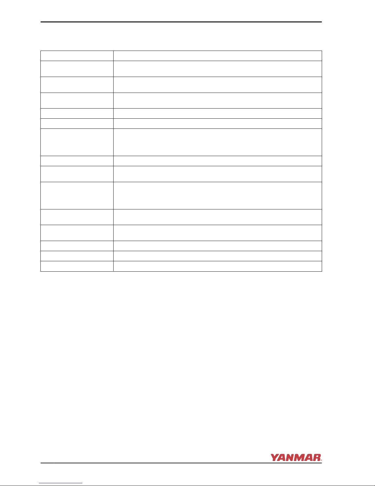
MAJOR COMPONENTS AND FUNCTIONS
Name of Component Function
Decompression Lever
Opens the exhaust valve and releases cylinder pressure to aid in manual engine
starting
Fuel Filter
Removes dirt and water from the fuel. Drain the filter periodically. The filter element
(filter) should be replaced periodically.
Fuel Feed Pump
(Priming Lever)
Pumps fuel from the tank to the fuel injection system. Pumping the priming lever
up and down supplies fuel to the engine when the fuel system needs to be primed.
Engine Oil Filler Port Filler port for engine oil
Marine Gear Oil Filler Port Filler port for marine gear oil
Engine Oil Filter
Filters fine metal fragments and carbon from the engine oil. Filtered engine oil is
distributed to the engine’s moving parts. The filter is a spin-on type and the element
should be replaced periodically. See Replacing the Engine Oil Filter Element on
page 50.
Cooling System Direct seawater cooling
Seawater Pump
Pumps seawater from outside the vessel and through the engine. The seawater
pump has a replaceable rubber impeller.
Zinc Anode
The metal surfaces of the seawater cooling system are prone to corrosion. The
zinc anode is installed in the cylinder block to prevent this. The surface of the zinc
anode erodes so it needs to be replaced at fixed intervals in order to fully protect
the seawater cooling system of the engine.
Intake Silencer (Air
Cleaner)
The intake silencer guards against dirt entering the engine induction system and
reduces the noise of air intake.
Nameplates
Nameplates are provided on the engine and the marine gear and contain the
model, serial number and other data.
Starter Motor The starter motor cranks the engine and is powered by the battery.
Alternator The alternator is belt driven and generates electricity to charge the battery.
Engine Oil Dipstick Gauge stick for checking the engine oil level
PRODUCT OVERVIEW
14 GM Series Operation Manual
© 2007 Yanmar Marine International
CONTROL EQUIPMENT
The control equipment at the helm makes remote control operation possible. It consists of
the instrument panel, which is connected to the engine by a wire harness, and the throttle
and shift console, which is connected by control cables to the engine control lever and marine
gear.
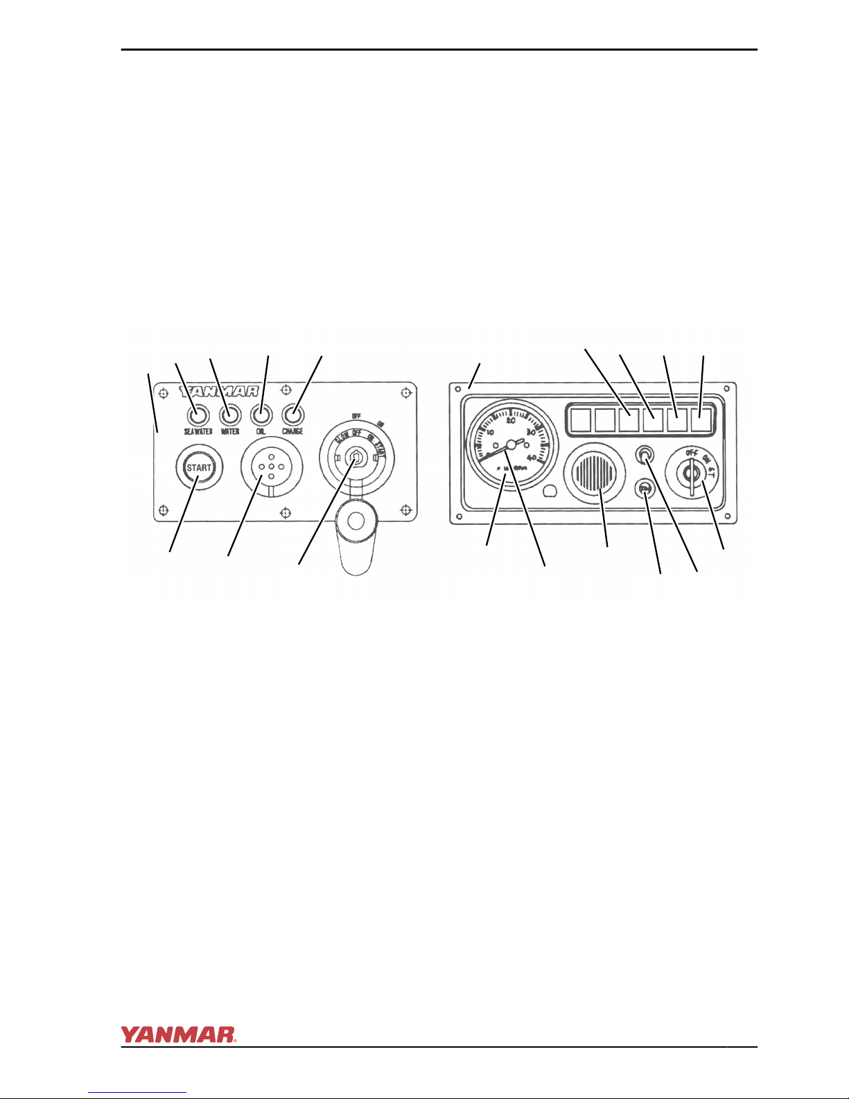
Instrument Panel (Optional)
Equipment and Functions
The instrument panel is located at the helm and is available in two options. The following
controls and indicators enable you to start, stop and monitor the condition of the engine during
operation.
Instrument Panel Options and Components
(2)
(3)
(4)
(5)
(8)
(7)
(6)
(10)
(12)
(7)
(9)
(8)
(11)
(6)
(5)(4)
(3)
(2)
(1)
0005848
Figure 7
1 – Option “A” Instrument Panel
2 – Seawater in Marine Gear Warning Lamp
3 – Water Temperature Warning Lamp
4 – Oil Pressure Warning Lamp
5 – Battery Low Charge Warning Lamp
6 – Key Switch
7 – Warning Buzzer
8 – Start Button
9 – Option “B” Instrument Panel
10 – Engine Tachometer
11 – Instrument Panel Light Switch
12 – Hour Meter
PRODUCT OVERVIEW
GM Series Operation Manual 15
© 2007 Yanmar Marine International

Gauges
Instrument Function
Tachometer Shows the engine rotation speed
Hour Meter
Shows the number of operating hours; can be used as a guide
for periodic maintenance checks. The hour meter is located at
the bottom of the tachometer.
Instrument Panel Lights
When turning the key switch to ON, the gauges will illuminate for
easier viewing.
Key Switch
When the key is in the OFF position
(Figure 8, (1)) the electric current is off. The
key can be inserted or removed in this
position.
OFF
ON
(2)
(1)
0005847
Figure 8
1 – OFF Position
2 – ON Position
The ON position (Figure 8, (2)) allows
electrical current to the controls and
equipment and allows the engine to keep
running. To stop the engine, keep the key
switch in the ON position and pull the engine
stop knob. After stopping the engine, turn
the key to the OFF position.
Engine Decompression Lever
The engine decompression lever
(Figure 9, (3)) releases cylinder pressure
to aid in manual starting.
(3)
(2)
(1)
0005838
Figure 9
1 – RUN Position
2 – Decompression Position
3 – Decompression Lever
Raising the decompression lever to the
decompression position (Figure 9, (2))
opens the exhaust valve and makes hand
cranking of the engine possible. Returning
the lever to its RUN position (DOWN)
(Figure 9, (1)) closes the exhaust valve and
normal engine operation can resume.
PRODUCT OVERVIEW
16 GM Series Operation Manual
© 2007 Yanmar Marine International

Indicators and Alarms (Optional)
When a sensor detects a problem during
operation, the indicator on the instrument
panel will light and an alarm will sound.
Indicators are located on the instrument
panel. The alarm is located on the back of
the panel. Under normal operating
conditions, the indicators are off.
Figure 10
Battery Low Charge Indicator
(Figure 10) - When the alternator output is
too low, the indicator will light. When
charging begins, the indicator will turn off.
No alarm will sound for low battery charge.
Figure 11
Water Temperature Indicator and Alarm
(Figure 11) - When water temperature
reaches the maximum allowable
temperature (95˚C [203˚F] or higher), the
indicator will light and the alarm will sound.
Continuing operation at temperatures
exceeding the maximum limit will result in
damage and seizure. Check the load and
troubleshoot the cooling system.
Figure 12
Engine Oil Low Pressure Indicator and
Alarm (Figure 12) - When the engine oil
pressure falls below normal, the oil pressure
sensor will send a signal to the indicator
causing it to light and the alarm to sound.
Stop operation immediately to avoid
damage to the engine. Check the oil level
and troubleshoot the lubrication system.
Figure 13
Water in Sail-Drive Seal Indicator and Alarm
(Figure 13) - When seawater is detected
between the seals of the sail-drive, the
indicator will light and the alarm will sound.
Engine Stop Control
The engine is stopped by pulling out the
engine stop knob (Figure 14, (1)). This
cable is connected to the engine stop lever
and cuts off the fuel supply to the engine.
(3)
(1)
(2)
0005842
Figure 14
1 – Engine Stop Knob
2 – Bulkhead
3 – Engine Stop Cable
PRODUCT OVERVIEW
GM Series Operation Manual 17
© 2007 Yanmar Marine International
Alarms
Check that indicators and alarms are working normally when the key is turned to ON.
Key Switch OFF ⇒ ON START ⇒ ON
Engine Before start Running
Alarm Sound No sound
Indicators
Battery Low Charge Indicator ON OFF
Water Temperature Indicator OFF OFF
Engine Oil Low Pressure Indicator ON OFF
Water In Sail-Drive Indicator OFF OFF
Note: All warning indications will continue until the engine starts or the key switch is in the
OFF position.
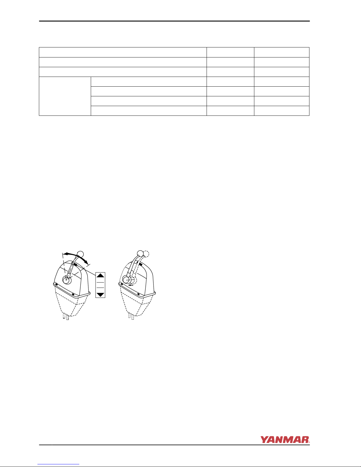
Optional Single-Lever Throttle
and Shift Console
This console (Morse Type) uses a single
lever to operate the throttle and the shifting
mechanism.
FORWARD (FWD) (Figure 15, (1)) - The
drive shaft is engaged and the engine
propels the vessel forward.
FWD
REV
NEUTRAL
IPULLI
CLUTCH
(1)
(2)
(3)
(4)
0005846
Figure 15
1 – FORWARD (FWD)
2 – NEUTRAL (N)
3 – REVERSE (REV)
4 – Pull out the lever to disengage the
clutch.
NEUTRAL (N) (Figure 15, (2)) - The drive
shaft is disengaged from the propeller and
the engine idles.
REVERSE (REV) (Figure 15, (3)) - The
drive shaft is engaged and the engine
propels the vessel aft.
With the lever in the NEUTRAL position, pull
the lever out from the console
(Figure 15, (4)) to disengage the clutch.
The lever controls the direction of the vessel
(ahead or astern) and acts as an
accelerator, increasing the engine speed
(rpm) as it is pushed further in the FWD or
REV direction. When the lever is pulled out,
engine speed can be controlled without
moving the vessel. The clutch is disengaged
and the vessel is in NEUTRAL (no-load
position).
Note: Yanmar recommends the use of a
single-lever type console for the remote
control system. If only a two-lever type is
available in the market, reduce engine
speed to 1000 rpm or less before engaging
and disengaging the marine gear clutch.
PRODUCT OVERVIEW
18 GM Series Operation Manual
© 2007 Yanmar Marine International

BEFORE YOU OPERATE
This section of the Operation Manual
describes diesel fuel and engine oil, and
how to replenish them. It also describes the
daily engine checks.
Before performing any operations within this
section, review the Safety section on
page 3.
DIESEL FUEL
Diesel Fuel Specifications
NOTICE: Only use diesel fuels
recommended by Yanmar for the best
engine performance, to prevent engine
damage and to comply with EPA
warranty requirements. Only use clean
diesel fuel.
Diesel fuel should comply with the following
specifications. The table lists several
worldwide specifications for diesel fuels.
DIESEL FUEL
SPECIFICATION
LOCATION
ASTM D975 No. 2-D, No.
1-D,
USA
EN590:96 European Union
ISO 8217 DMX International
BS 2869-A1 or A2 United Kingdom
JIS K2204 Grade No. 2 Japan
GM Series Operation Manual 19
© 2007 Yanmar Marine International

Additional Technical Fuel
Requirements
• The fuel cetane number should be 45 or
higher.
• The sulfur content must not exceed 0.5%
by volume. Less than 0.05% is preferred.
• NEVER mix kerosene, used engine oil or
residual fuels with the diesel fuel.
• Water and sediment in the fuel should not
exceed 0.05% by volume.
• Keep the fuel tank and fuel-handling
equipment clean at all times.
• Ash content not to exceed 0.01% by
volume.
• Carbon residue content not to exceed
0.35% by volume. Less than 0.1% is
preferred.
• Total aromatics content should not
exceed 35% by volume. Less than 30% is
preferred.
• PAH (polycyclic aromatic hydrocarbons)
content should be below 10% by volume.
• Do not use Biocide.
• Do not use kerosene or residual fuels.
Handling Diesel Fuel
!
DANGER
Only use diesel fuel in the fuel tank. Filling
the fuel tank with gasoline may result in a fire
and will damage the engine. NEVER refuel
with the engine running. Wipe up all spills
immediately. Keep sparks, open flames or
any other form of ignition (match, cigarette,
static electric source) well away when
refueling.
ALWAYS store any containers containing
fuel in a well-ventilated area, away from any
combustibles or sources of ignition.
ALWAYS put the diesel fuel container on the
ground when transferring the diesel fuel
from the pump to the container. Hold the
hose nozzle firmly against the side of the
container while filling it. This prevents static
electricity buildup which could cause sparks
and ignite fuel vapors.
BEFORE YOU OPERATE
20 GM Series Operation Manual
© 2007 Yanmar Marine International
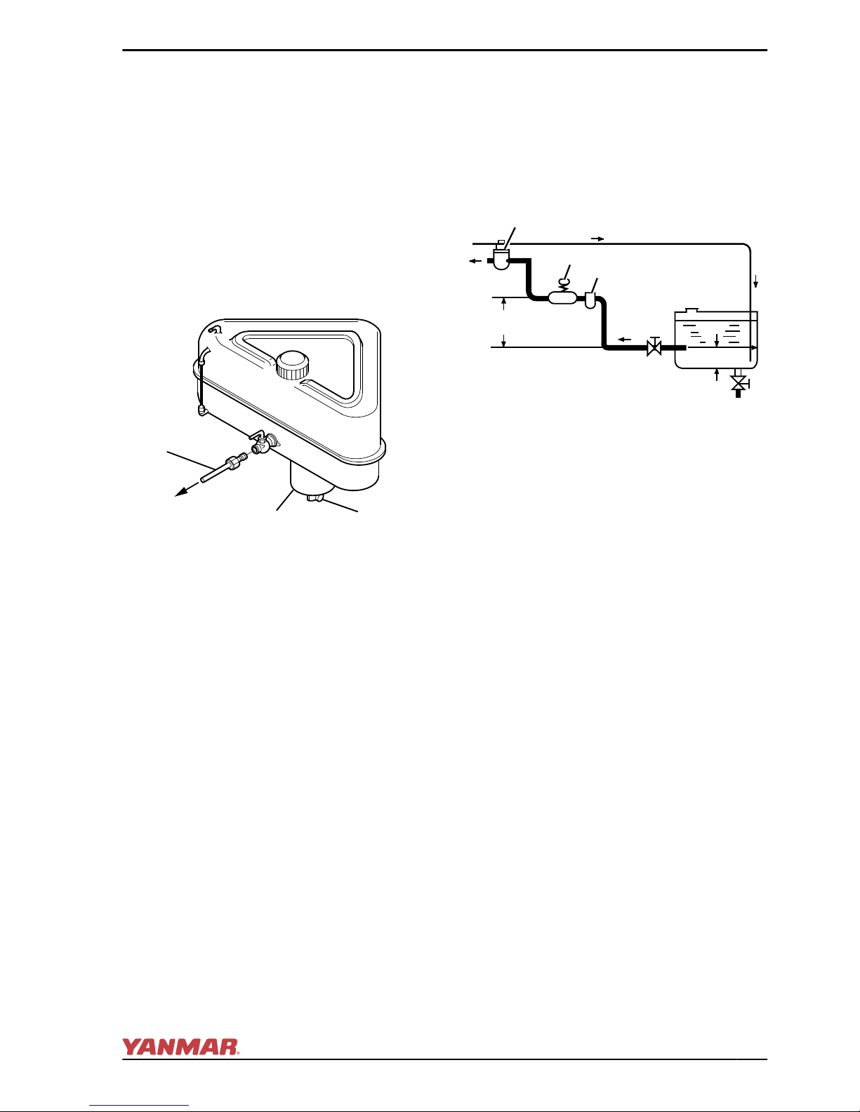
Fuel Tank (Optional)
NOTICE: Water and / or dust in the fuel
may cause engine failure. When fuel is
stored, check that the inside of the
storage container is clean and dry, and
that the fuel is stored away from dirt or
rain.
Install a drain cock (Figure 1, (2)) at the
bottom of the fuel tank to remove water and
contaminants from the sediment bowl
(Figure 1, (1)).
0004542
(3)
(1)
(2)
Figure 1
1 – Sediment Bowl
2 – Drain Cock
3 – Fuel Line to Engine
The fuel outlet should be positioned
20 to 30 mm (0.75 to 1.125 in.) above the
bottom of the tank (Figure 2, (4)) so that
only clean fuel is distributed to the engine.
Fuel System
Install the fuel line from the fuel tank to the
fuel injection pump as shown in Figure 2.
The recommended fuel / water separator
(Figure 2, (3)) (optional) is installed at the
center section of that line.
(1)
(2)
(3)
(8)
(10)
(4)
(6)
(7)
(9)
(5)
0004788
Figure 2
1 – Fuel Filter
2 – Fuel Feed Pump (Priming Lever)
3 – Fuel / Water Separator (Optional)
4 – Approximately 20 - 30 mm
(0.75 - 1.125 in.)
5 – Within 500 mm (20 in.)
6 – Drain Cock
7 – Fuel Cock
8 – Fuel Return Line
9 – To Fuel Injection Pump
10 – Fuel Tank
BEFORE YOU OPERATE
GM Series Operation Manual 21
© 2007 Yanmar Marine International
Filling the Fuel Tank
Before filling the fuel tank for the first
time:
Rinse the fuel tank with kerosene or diesel
fuel. Dispose of waste properly.
To fill the fuel tank:
NOTICE: Operate bilge ventilation
(blowers) for a minimum of 5 minutes to
purge fumes from engine compartment
after refueling. Never operate bilge
blower while refueling. Doing so can
pump explosive fumes into the engine
compartment and result in an explosion.
1. Clean the area around the fuel cap.
2. Remove the fuel cap from the fuel tank.
3. Fill the tank with clean fuel free of oil and
dirt. WARNING! Hold the hose
nozzle firmly against the filler port
while filling. This prevents static
electricity buildup which could
cause sparks and ignite fuel vapors.
4. Stop fueling when the gauge shows the
fuel tank is full. CAUTION! NEVER
overfill the fuel tank.
5. Replace the fuel cap and hand-tighten.
Over-tightening the fuel cap will
damage it.
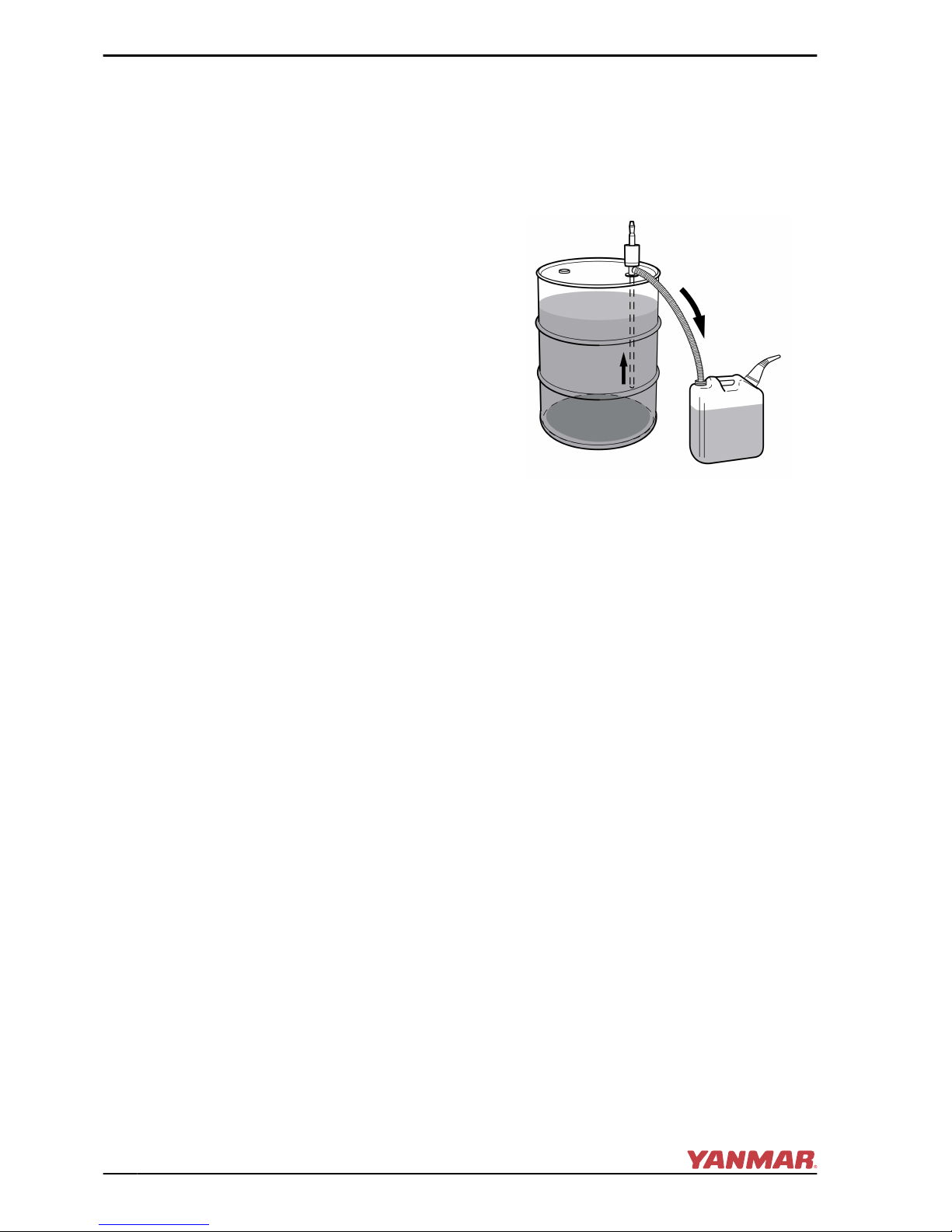
If filling the tank from a storage container
(Figure 3), keep the fuel container
stationary for several hours to allow any dirt
or water to settle to the bottom of the
container. Use a pump to extract the clear,
filtered fuel from the top of the container.
0004512
Figure 3
BEFORE YOU OPERATE
22 GM Series Operation Manual
© 2007 Yanmar Marine International
 Loading...