

Page 1

● Thank you very much for purchasing this Yamato
Pure LineⓇ WL220T.
● Please read the “Operating Instructions” and
“Warranty” before operating this unit to assure proper
operation. After reading these documents, be sure to
store them securely together with the “Warranty” at a
handy place for future reference.
Warning:
Before operating the unit, be sure to read
carefully and fully understand important
warnings in the operating instructions.
Water Purifier
R
Pure Line
○
WL220T
Instruction Manual
Second edition
Yamato Scientific America Inc.
Santa Clara,CA
The documents are printed on recycled paper.
Page 2

Page 3

Contents
1. Safety precautions ............................................................................................................................. 1
Explanation of pictograms ................................................................................................................. 1
List of symbols ................................................................................................................................... 2
Warning・Caution .............................................................................................................................. 3
2. Before operating the unit ................................................................................................................... 5
Installing procedures and preparation before operation ................................................................... 5
Precautions for installation ................................................................................................................ 6
Installation procedures ....................................................................................................................... 8
3. Names and Functions of Parts ........................................................................................................ 13
Main unit .......................................................................................................................................... 13
Piping diagram ................................................................................................................................. 14
Operation panel ............................................................................................................................... 16
4.Operation Method ............................................................................................................................. 17
Pre-start preparation and checks .................................................................................................... 17
Operation method ............................................................................................................................ 17
Water supply to the tank .................................................................................................................. 18
Water supply to the constant temperature and humidity chamber .................................................. 18
Selecting the water quality unit ........................................................................................................ 19
Water quality and water quality display ........................................................................................... 20
Water quality characteristics data (reference) ................................................................................. 21
Data of deterioration of tank water quality (reference) .................................................................... 22
5. Useful Functions .............................................................................................................................. 23
List of optional parts ......................................................................................................................... 23
Setting of the input terminal for remote water supply (optional)...................................................... 24
Setting of the external alarm output (optional) ................................................................................ 24
6. Maintenance procedures ................................................................................................................. 25
Maintenance and inspection ............................................................................................................ 25
Replacing the ion exchange resin cartridges .................................................................................. 25
Resetting after replacement of consumable parts (when an alarm is triggered) .......................... 26
Washing the supply hose strainer ................................................................................................... 27
Replace the piping hose. ................................................................................................................. 27
7. When the unit is not to be used for a long time or when disposing ................................................ 28
Requests in case of disposal ........................................................................................................... 28
8.Troubleshooting Guide ..................................................................................................................... 30
Display and contents ....................................................................................................................... 30
If a malfunction is suspected ........................................................................................................... 31
Troubleshooting ............................................................................................................................... 32
9. After sales service and warranty ..................................................................................................... 33
When requesting a repair ................................................................................................................ 33
10.Specifications ................................................................................................................................. 34
11.Electric diagram .............................................................................................................................. 35
Wiring diagram ................................................................................................................................. 35
Part symbols of wiring diagram ....................................................................................................... 36
12.Replacement part table .................................................................................................................. 37
13. List of dangerous materials ........................................................................................................... 38
14. Standard installation manual ......................................................................................................... 39
Page 4

1. Safety precautions
About pictograms
A variety of pictograms are indicated in this operating instruction and on
products for safe operation. Possible results from improper operation
ignoring them are as follows.
Be sure to fully understand the descriptions below before proceeding to the
text.
Warning
Caution
Indicates a situation which may result in minor injury (Note 2) and
property damages (Note 3.)
(Note 1)Serious injury means a wound, an electrical shock, a bone fracture or intoxication that may
leave after effects or require hospitalization or outpatient visits for a long time.
(Note 2)Minor injury means a wound or an electrical shock that does not require hospitalization or
outpatient visits for a long time.
(Note 3)Property damage means damage to facilities, devices and buildings or other properties.
Meanings of pictograms
This pictogram indicates a matter that encourages the user to adhere to warning
(“caution” included).
Specific description of warning is indicated near this pictogram.
This pictogram indicates prohibitions
Specific prohibition is indicated near this pictogram.
This pictogram indicates matters that the user must perform
Specific instruction is indicated near this pictogram.
Indicates a situation which may result in death or serious injury (Note 1.)
Explanation of pictograms
1
Page 5

General warnings
Danger!: High
voltage
Danger!: High
temperature
Danger!: Moving
part
Danger!: Hazard
of explosion
General cautions
Electrical shock!
Burning!
Caution for no
liquid heating!
Caution for water
leak!
For water only
Poisonous
material
General bans
Fire ban
Do not
disassemble
Do not touch
General
compulsions
Connect ground
wire
Install levelly
Pull out the power
plug
Regular
inspection
Warning
Caution
1. Safety precautions
List of symbols
Prohibitions
Compulsions
2
Page 6

1. Safety precaution
Warning
Never operate the unit in an atmosphere containing flammable or explosive gas
Never operate the unit in an atmosphere containing flammable or explosive gas.
Otherwise, an explosion or a fire may result since the unit is not explosion-proof.
See section “13. List of dangerous materials” on page38.
Be sure to connect the earth wire.
Connect the earth wire to the earth socket outlet. If the earth socket outlet is not available, use the
grounding adaptor to connect the earth lead to the ground. Otherwise, electric leakage occurs,
causing electric shock or fire.
Be sure to insert the power cord plug firmly.
Insert firmly the power cord to the extreme depth of the main body power socket. If not inserted
firmly, overheat or fire may occur.
Stop using in case of abnormality
Should any fuming or questionable odor be detected, turn OFF the power switch on the righthand side of main body immediately, and disconnect the power plug from the master power
supply. Then request inspection to the shop from which you have purchased the product, our
sales office or our customer service center.
If left unattended, such abnormality may cause fire or electric shock.
Never use electrical power cords bundled.
When these are used bundled, they might overheat causing a fire.
Take care not to damage electrical power cords.
Avoid tightly bend, pull with a strong force or twist to prevent electrical power cords from damaging.
A fire or an electrical shock may result.
Never try to disassemble or alter the unit.
Never try to disassemble or alter the unit. A malfunction, a fire or an electrical shock may result.
Always keep the tap closed when the product is not operated.
Always keep the tap closed when the product is not to be operated (during nighttime or holidays).
Otherwise, water leakage may occur.
Do not place an object on this product.
Any object, if placed on the system, may drop. Placement of the solvent may also cause trouble.
Do not ride on this product.
The person riding on the product may overturn or the system may be damaged, resulting in injury
or trouble.
Warning・Caution
3
Page 7

1. Safety precautions
Warning
Install the unit at a place higher than the connecting port on the constant
temperature and humidity chamber.
This unit is dedicated for the constant temperature and humidity chamber and supplies water to
it by gravity. Installing the unit at a place lower than the connecting port of the constant
temperature and humidity chamber may cause insufficient supply of water to the chamber or a
malfunction.
When installing the unit on the constant temperature and humidity chamber, be
sure to use the optional “Installation tray”(See “5. Useful Functions” on P. 23).
Do not adjust the reducing valve.
The reducing valve has been set to the water supply rate of about 1.0L/min(raw water pressure:
3×100kPa, reducing valve pressure:0.4×100kPa) at the factory. Never attempt to readjust the
reducing valve.
If the factory setting of the valve is lost, water leak or reduction in flow may result.
Cut the connecting hose of the constant temperature and humidity chamber to a
necessary length before use.
Run the connecting hose for the constant temperature and humidity chamber without a kink or
twisting so that any trap (water pool) will not occur at any point along the hose.
Be sure to install the unit level.
The unit is equipped with a leak detecting sensor in case of a leak accident. Be sure to install the
unit level since the sensor may not operate properly if the unit is installed inclined by three degree
or more in back and forth or left or right direction.
Caution
In case of thundering
When thundering begins, turn OFF the power switch on the right-hand side of main body
immediately and pull out the power cord.
Otherwise, lightening may cause failure of the control circuit of the system or may cause fire
and electric shock.
In case of power failure
Although the unit will stop when a power outage occurs, the unit will not supply water to the tank
if water is left in the tank at the recovery from the power outage while the power switch is ON. In
contrast, it will start supplying water to the tank to the highest level if it is empty at the time of
recovery.
Turn the power switch on the right side of the unit to OFF for safety when a power outage occurs.
To resume operation, follow the steps in “Turning power on” in the ”4.Operation Method” on P.17
Warning・Cautions
4
Page 8

Installing procedures and preparation before operation
Warning
・ Be sure to connect the earth wire (green wire of the power cord) to the earth wire or to
the earth terminal.
・ Never connect the earth wire to the gas pipe or water pipe, in order to prevent fire.
・ The earth wire must never be used for grounding of the telephone line and lightning
arrestor. This is to prevent fire and electric shock.
・ Never use the branch socket outlet because it causes hazardous heat generation.
Used of ground socket outlet recommended
When using a diode socket outlet
When there is no ground terminal.
●In this case, class D grounding work is
necessary and please consult your dealer or
our customer service center.
Ground adaptor
●Insert the ground adaptor into a power plug
confirming the polarity of the outlet. Connect
the grounding wire (green) of the ground
adaptor to the ground terminal on the power
supply equipment。
Take special care not to install the
unit at a place described below:
・ Uneven surfaces or dirty surfaces
・ Where flammable gas or corrosive
gas exists
・ Where the ambient temperature is
5℃ or less
・ Where the ambient temperature is
35℃ or more
・ Where temperature changes
severely
・ Where dusty and humidity is high
・ Where subject to direct sunlight
・ Where vibration is severe
・ Where unstable power supply
・ Where uneven floor(within
reference±3 degree)
・ Where raw water pressure is high
・Where with raw water pressure is
low
・ Outdoors
・At a place lower than the suction
port of the constant temperature
and humidity chamber
・On a device or a laboratory table
(with locked adjusters, etc.)
It is recommended to secure the space of the range wider than the one shown above around
the product.
Toward front
by 30cm or more
10cm or more
3-pole power plug with an
earth terminal
Earth wire
3-pole power plug with an
earth terminal
w
G
W
Earth pole
10cm or more
10cm or more
1. Be sure to connect the earth wire.
2. Before operating the unit
2. Carefully select an installation site.
5
Page 9

2. Before operating the unit
● Never operate the unit in an atmosphere containing flammable or explosive gas. Since
This product is not of an explosion-proof structure. Accordingly, when the power switch
on the right side of the unit is turned ON/OFF and in the course of operation, arc may
occur, possibly causing fire and explosion.
● See the section “13. List of dangerous materials” on page 38 for flammable and explosive
gases.
● If it is not installed level, the leak detection function may not operate properly when
water should leak at the pipes in the unit. The permissible error in the levelness
shall be ±3 degree and properly set the adjusters of the constant temperature and
humidity chamber or of the laboratory table to make it level.
● The unit weight is about 17kg. Handle with care during transportation and installation.
● Use the socket outlet appropriate to the power capacity (1A or larger capacity).
● The deficient power capacity causes not only decrease in the water supplying rate, but
makes correct control impossible due to drop of the supply voltage. Always connect the
product to the power supply system with sufficient allowance in the supply voltage.
Power capacity : WL220T Single phase AC100~240V 0.5A or less
● Note that the use of extension with a cord reel may cause drop of the voltage. Avoid
starburst connection with branch socket outlet so as to prevent fire and electric shock.
爆発性ガス
可燃性ガス
WL220T
W
L
2
2
0
T
Flammable gas
Explosive gas
Precautions for installation
3. Never operate the unit in an atmosphere containing flammable or explosive gas.
4. Install on a level surface.
5. Take the power supply from the dedicated socket outlet.
6
Page 10

● Connect the attached power cord to the power socket. Confirm that the power switch on the right
side of the main body is OFF, and connect the power cord plug to the socket outlet. The power cord
plug attached to this product is the three-wire cord including the earth wire, and the plug is also of
a ground plug. If the socket outlet to be used does not match the plug (that is, the 2P outlet), use
the ground adapter. When using this adapter, be sure to connect the earth lead wire to the ground.
●Never use electrical power cords bundled. When these are used bundled, they might overheat
causing a fire.
●Do not convert, forcibly bend, twist or pull the power cord. Otherwise, a fire or an electrical shock
may result.
●Do not place the power cord under a desk or a chair, or sand between objects to avoid it from being
damaged. Otherwise, a fire or an electrical shock may result.
●Do not place the power cord close to a stove or other heat generating device. Sheath of the cord
may burn and result in a fire or an electrical shock.
●If the power cord should be damaged (exposure of core wire or disconnection), immediately turn
the power supply in the right side of the main body off, disconnect the power plug and ask your
dealer to replace the cord. If the unit is operated with a damaged power cord, a fire or an electrical
shock may result.
●Connect the power cord to an appropriate wall outlet or distribution board.
● Use the supply water pressure within a range of 0.5~5×100kPa(0.5~5kgf/cm2) 24 hours a
day.
Note that the water feeding range to the tank becomes 1.0 L/min or less at the raw water pressure
of 1.0×100kPa (1kgf/cm2) or less.
● The raw water pressure range is the same even when the optional water inlet unit (see Page 23)
is used.
● When installing the unit at a higher place such as on the constant temperature and humidity bath,
the product may fall off during an earthquake and cause a dangerous situation. We strongly
recommend using the optional installation tray to stably secure the unit. The installation tray can
accept leak water and discharge using the drain hose when a water leak accident should occur.
Power outlet
Power cord
6. Connecting the power cord
2. Before operating the unit
Precautions when installing the unit
7. Handling of a power cord
8. Be sure to keep the raw water pressure from water supply within the specified range.
9. Use the installation tray (optional).
7
Page 11

2. Before operating the unit
●Take out the water supply hose included in the accessories of the main unit.
●Failure to securely connect it may cause water to gush out and to result in a leak.
●First tighten the main valve before connecting the water supply hose to the water pipe side.
(1)Wrap included seal tape around
the nipple ① of the water supply
hose. Wrap the seal tape
clockwise looked from you two to
three rounds while lightly pulling it
and cut off excess portion.
(2)Connect the water pipe side screw
and the nipple ① using a wrench.
Take care so that the cap part of
the Y-strainer ② will be the under
side.
※The size of the water supply hose screw is 1/2 male. When the size of the water pipe
side screw is other than 1/2 female, prepare a nipple of a different diameter.
※Use tap water as raw water.
①Nipple
Screw dia.1/2
②Y-strainer
Cap part
Seal tape
①Nipple
Screw dia.1/2
Water pipe
side screw
1. Always connect the feed water hose firmly.
2. Make connections on the water faucet side.
Installation procedures
8
Page 12

2. Before operating the unit
(1) Remove rubber cap from the water
inlet plug ⑧.
(2) With the sleeve slid in the direction
indicated with arrow, and insert the
main body water inlet plug ⑧ to
the socket ⑨ . Connection is
completed when the sleeve returns
to the original position when
released. The socket has a built-in
valve. This valve does not open
and allow water to flow unless
connected with the inlet valve⑧.
Main body side
The “water inlet plug unit” has its own valve and enables you to remove the water supply hose
without tightening the main plug of the water pipe. It also has a structure that prevents the
connection to the water plug from loosening even when tap water pressure fluctuates.
Take out the hook included in the
accessories of the main unit.
(1) Attach the hook on the back of this
product. The hook has a magnet
and can be placed at any place you
want.
(2) Put the tank drain hose on the
hook.
※ Although the tank drain hose is
plugged, if it is laid on the floor and
the plug comes off, water in the tank
will be drained. Be sure to put the
tank drain hose on the hook. If you
use the optional “installation tray”
(See “5 Useful function”. on P-23), it
will not cause any problem if you do
not use the hook and connect the
tank drain hose directly to the
installation tray.
Sleeve
Hook
Tank drain hose
⑨ Socket
⑧ Inlet valve
Valve
Installation procedures
3. Carry out connection on the main body side.
4. If you want a part with a valve, use the optional “water inlet plug unit” (see P.29).
5. Put the tank drain hose on the hook.
9
Page 13

2.Before operating the unit
Take out the connecting hose of the constant temperature and humidity chamber(φ9mm×
φ13mm 3m) included in the accessories of the main unit.
(1)Remove the screws on that hold the left side cover to the main unit.
(2)Remove the screws that hold the cock installing plate.
(3)Connect the connecting hose of the constant temperature and humidity chamber(I.D.:
φ9mm)to the cock. After connecting the hose, secure it with attached hose clamp.
(4) Run the connected hose through the hole on the back plate and connect to the
connecting port on the constant temperature and humidity chamber.
※ Cock has been shipped in the closed status. After connecting the hose, turn the cock by
90° anticlockwise to open it.
※ Cut the connecting hose of the constant temperature and humidity chamber into an
appropriate length to prevent it from kinking or twisting.
When the optional “remote water supply input terminal” is used
(1)Install the connecting hose of the constant temperature and humidity chamber to the
solenoid valve nipple on the back side.
Cock securing
plate
Left side cover
Cock (open state)
Constant temperature
and humidity chamber
connecting hose
Constant temperature
and humidity chamber
connecting hose
Hose clamp
Installation procedures
6. Install the connecting hose of the constant temperature and humidity chamber to
the cock on the left side of the main unit.
10
Page 14
2. Before operating the unit
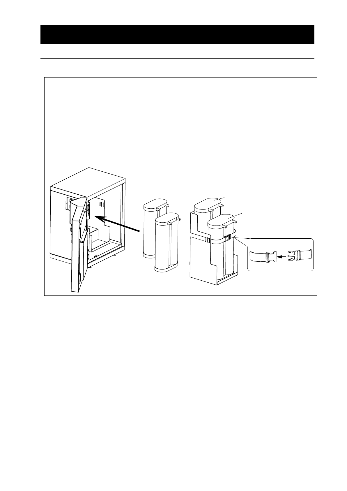
● Install the ion exchange resin cartridge (CPC-P, CPC-E) as follows:
(1) Confirm that the power switch on the right side of main body is OFF and that the faucet is
closed.
(2) Install the selected ion exchange resin cartridge firmly to the resin installation plate inside
the system. For installation of the ion exchange resin cartridge of WL220, provide CPCP in the front and CPC-E in the rear.(See Figs. 01)
(3) Secure the ion exchange resin cartridge with a band to the resin installation plate.
(See Figs. 02)
CPC-E
樹脂(後)
CPC-P
樹脂(前)
バンド
Band
CPC-E resin
(rear)
CPC-P resin
(front)
Fig. 01
Fig. 02
Installation procedures
7. Connect the ion exchange resin cartridge(CPC-P, CPC-E) firmly.
11
Page 15

2. Before operating the unit
●Connect ion exchange resin cartridges (CPC-C and CPC-E) as follows.
Remove a rubber cap from the inlet and outlet of each ion exchange resin cartridge.
(1) Press the coupler with ( 4 ,OUT) mark into the
outlet (right side) of the ion exchange resin
cartridge (CPC-E) till it clicks.
(2) Press the coupler with ( 3 ,IN) mark into the inlet
(left side) of the ion exchange resin cartridge
(CPC-E) till it clicks and press the coupler with
( 2 ,OUT) mark into the inlet (right side) of the ion
exchange resin cartridge (CPC-P) till it clicks.
(3) Press the coupler with ( 1 ,IN) mark into
the inlet (left side) of the ion exchange resin
cartridge (CPC-P) till it clicks. (See Fig. 03)
※ Initially, the coupler may be hard to insert and application of excessive force for insertion may
cause the insertion port to break. When this is hard to insert, carry out connection in a state as
removed from the resin installation plate while taking care not to insert in the bent state.
※ Once the coupler is inserted, pull on the hose to confirm connection and to make sure that the
coupler is not disconnected.
※ Set the coupler connected to the ion exchange resin cartridge (CPC-P) to face laterally (on the
left side as viewed from the front). If the coupler is allowed to face downward, it contacts the
door back plate to make door closing impossible.
※The coupler can be removed with ease by pulling on it while pressing a black portion to the depth.
For removal, reverse the order (1→2→3→4) of installation. Note also that water may drip from
the ion exchange resin cartridge when the coupler is disconnected.
※ Reverse installation of ion exchange resin cartridges or wrong connection of IN and OUT of
each cartridge may cause failure, resulting in shorter service life of the cartridges.
Install the unit at a place higher than the connecting port on the constant temperature
and humidity chamber. When installing the unit on the constant temperature and
humidity chamber, be sure to use the optional “Installation tray”((See “5 Useful
function”. on P-23).
The product may topple down and cause a personal injury due to an earthquake or an
unexpected shock. Implement appropriate preventive measures for safety.
CPC-P
樹脂(前)
CPC-E
樹脂(後)
採水口へ
給水口から
Fig. 03
CPC-E resin
(rear)
CPC-P resin
(front)
To water supplying port
From water
inlet
Installation procedures
8.After installation
12
Page 16

3. Names and Functions of Parts
Water quality sensor
Leak detecting sensor
Ion exchange resin cartridge
Front:CPC-P, back:CPC-E
Product code:253262
※CPC-P and CPC-E are set
Air filter
Operation
panel
Rating
sticker
Serial number sticker
Water supply
port
Power cord
Ext. alarm output
terminal (optional)
Remote watersupply
input terminal
(optional)
Decorative board
Reducing
valve
Power switch
○: [OFF]
―: [ON]
Internal tank
Cock
Tank drain hose
Leak detecting
sensor
Solenoid valve (optional) for
supply to the constant
temperature and humidity
chamber
Main unit
Note: The reducing valve has been set to the water supply rate of about 1.0L/min(raw water pressure:3×
100kPa, reducing valve pressure:0.4×100kPa) at the factory. Never attempt to readjust the reducing
valve.
Front Back
13
Page 17

3. Names and Functions of Parts
1. Water supply hose
6. Water quality sensor
2. Reducing valve
7. Tank
3. Water supply solenoid valve
8. Air filter
4. Ion exchange resin cartridge (CPC-P)
9. Cock
5. Ion exchange resin cartridge (CPC-E)
10. Drain cock
1. Water supply hose
7. Tank
2. Reducing valve
8. Air filter
3. Water supply solenoid valve
9. Cock
4. Ion exchange resin cartridge (CPC-P)
10. Drain cock
5. Ion exchange resin cartridge (CPC-E)
11. Water supply solenoid valve (optional)
6. Water quality sensor
②
③
④
⑤
⑥
⑦
⑩
⑧
⑨
②
③
④
⑤
⑥
⑦
⑨
⑧
⑩
⑪
Optional
①
To constant temp. &
humid. chamber
Tap water main valve
①
To constant temp. & h
umid.
chamber
Tap water main valve
Piping diagram
※ The reducing valve pressure has been set to 0.4×100kPa(raw water pressure:3×100kPa)
at the factory.
Remote water supply input terminal (optional)
※ The reducing valve pressure has been set to 0.4×100kPa(raw water pressure:3×100kPa)
at the factory.
14
Page 18

3.Names and functions of parts
①
②
③
④
⑤
⑦
⑥
⑥
Water supply to the tank
● Ion exchange water flows through ① reducing valve, ②water supply solenoid valve, ③ & ④ion
exchange resin cartridges (CPC-P & CPC-E) and ⑤water quality sensor and is supplied to the ⑥
tank.
Water supplying to the constant temperature and humidity chamber
●Ion exchange water in the tank will be supplied to the constant temperature and humidity chamber
after flowing through the ⑥ tank and the ⑦ cock when the solenoid valve of the constant
temperature and humidity chamber opens.
※ The water supply solenoid valve opens or closes in response to signals from the constant
temperature and humidity chamber in the case the supply terminal option is employed for the
constant temperature and humidity chamber.
15
Page 19

3.Names and functions of parts
No.
Nomenclature
Control/operation
①
Water quality display
Displays the quality of deionized water.
②
Information display
Displays errors, replacement timing of consumable
parts and the unit operation status.
③
CLR key
Used when consumables are replaced
④
UNIT key
Selects the water quality unit (×10-4S/m⇔×104Ω・m)
⑤
Water quality unit lamp
The side of the water quality unit selected will come on.
0 1 2 3 4 5 6 7 8
9
A B C D E F G H I
J
K L M N O P Q R S
T
U V W X Y Z -
Blank
①
③
⑤ ④ ②
Operation panel
List of displayed characters
16
Page 20

4.Operation Method
Be sure to check again before use.
(1)Confirmation of water feed
・Confirm that the feed water hose is firmly connected.
・Open the faucet.
・Confirm that the connection of feed water hose is free from water leakage.
(2)Confirmation of power supply
・Check if the power cord is connected to the appropriate socket outlet.
・Confirm that the power cord is inserted to the depth of main body power cord socket outlet.
Upon completion of preparation, start operation as follows.
Power application
Power switch
OFF ON
① Set the power switch on the right side of main
body to “ON(―).”
Operation panel (initial display)
●Initial display for 4 seconds
l
○
Pre-start preparation and checks
Operation method
17
Page 21

4.Operating procedures
Water supply to the tank
When the tank is empty
● Automatically start supplying water to the
tank.
● The information display shows an
animation of supplying water to the tank.
Animation of supplying water to the tank
When the tank is full or has remaining water
● Animation of supplying water to the tank is
turned off in the information display
※ After initial powering on or replacement of the ion exchange resin cartridge, discharge
water completely at the tank discharge port on the back when the tank has become full.
Be sure to turn power OFF because supplying water to the tank will start if power is ON.
※ If there is water remaining in the tank, supplying water to the tank will not start even when power
is turned ON.
Supplying water to the constant temperature
and humidity chamber
Standard specification(natural fall system)
●The solenoid valve in the constant
temperature and humidity chamber opens to
start supplying water to the constant
temperature and humidity chamber
automatically.
●The information display is blank.
Remote water supply terminal (optional)
●The optional remote water supply terminal
has a solenoid valve for supplying water.
●External output of the constant temperature
and humidity chamber opens the water
supply solenoid valve in WL220T to start
supplying water to the constant temperature
and humidity chamber automatically.
●The information display shows an animation
during water supply to the constant
temperature and humidity chamber.
Animation of supplying water to the constant
temperature and humidity chamber
Water supply to the tank
Water supply to the constant temperature and humidity chamber
18
Page 22

4.Operating procedures
Selecting the water quality unit
Press the UNIT key, and the water quality unit
can be changed.
To change the water quality unit:
● Electric conductivity (conductivity) display
●Specific resistance display
For details, refer to “Electric Conductivity (Conductivity)” of P. 20
Selecting the water quality unit
19
Page 23

4.Operation Method
Measuring the electric conductivity (conductivity)
The Water Quality Display of operation panel shows the electric conductivity at the outlet of ion
exchange resin cartridge. Use the displayed reading as a guideline to determine the cartridge
replacement timing. Read the conductivity while the electrode is fully immersed in water, that is,
while the deionized water is flowing.
Correct reading cannot be made in the following cases because of failure of immersion of electrode
into the water or the effects of air bubbles:
1. During initial operation period and while the unit is down
2. Immediately after replacement of ion exchange resin cartridge and the pretreatment cartridge
(optional).
Electric conductivity (conductivity)
・ The electric conductivity is the numerical value representing the easiness of the material to
conduct electricity. Water tends to conduct electricity more readily with increasing content of
dissolved electrolyte, that is, impurities. The numerical value of such conductivity decreases with
decreasing content of electrolyte.
・ The smaller numerical value of electric conductivity means higher purity of pure water.
Note however that the numerical value of electric conductivity refers only to electrolyte and not
to non-electrolytes (organic and colloidal substances, dissolved gases, microorganisms). The
value does not represent the total purity and should be handled only as one of indices to
represent the water purity.
・ The resistivity (R) is a factor representing the content the same as for the electric conductivity
(ρ). Since the resistivity is the reciprocal of electric conductivity, the higher numerical value
of resistivity means higher purity.
R[Ω・m]=
1
or
R[×104Ω・m]=
1
ρ[S/m]
ρ[×10-4S/m]
Accordingly, factors for the theoretical pure water are defined as follows:
R=18.2×10
4
Ω・m(18.2MΩ・cm)25℃
ρ=0.055×10⁻⁴S/m(0.055μS/cm)25℃
Water quality of deionized water
Deionized water
Water with the lowest electric conductivity can be obtained by eliminating most of
electrolytes in water, except that non-electrolytes can be removed. More or less
deterioration of purity may be observed immediately after replacement of resin or at
resumption of water flow after shutdown of the system.
Water quality and water quality display
20
Page 24

4.Operating procedures
0
2
4
6
8
10
12
14
16
18
20
0 100 200 300 400 500 600 700 800
※Tap water of Yamanashi Pref. ・・electric conductivity: 200×10-4S/m
Total water amount(L)
Specific resistance
(×10
4
Ω・
m)
Time (minute)
Specific resistance
(×10
4
Ω・
m)
Water quality characteristics data (reference)
The use life of the ion exchange resin cartridge is about 700L (at electric conductivity of 200×10-4S/m).
One of water quality characteristics of water immediately after replacement of the ion exchange resin
cartridge is the transient characteristic above which requires several minutes to be stable. Thus fill the
3L tank immediately after replacement of the ion exchange resin cartridge and then discharge water in
the tank completely at the discharge port. Use the data as a reference only since the same results will
not be always obtained depending on the specific cartridge or raw water quality.
21
Page 25

4.Operating procedures
Number of days (day)
Specific resistance
(×10
4
Ω・
m)
※Tap water of Kanagawa pref. ・・・Electric conductivity150×10-4S/m
Electric conductivity
(×10
-4
S/m
)
0
2
4
6
8
10
12
14
16
18
20
0 2 4 6 8 10 12 14 16 18 20 22 24 26 28
0
0.5
1
1.5
2
2.5
3
3.5
4
4.5
5
比抵抗値
電気伝導率
Specific resistance
Electric conductivity
Data of deterioration of tank water quality (reference)
The quality of pure water in the tank will deteriorate if it is left as it is. The water quality is A3 (electric
conductance: 1×10⁻⁴S/m or lower) at the time of supplying to the tank, which will be A1 (5×10⁻⁴S/m
or lower) in three days. The reason pure water shall be used for the constant temperature and
humidity chamber is to prevent accumulation of stone of humidifying water, which means pure water
having quality of A1 (5×10⁻⁴S/m or lower) or higher may be used. If the water in the tank is not
used for one month, the A1 quality (5×10⁻⁴S/m or lower) may be maintained.
Use the data as a reference only since the same results will not be always obtained depending on
the specific cartridge or raw water quality.
22
Page 26

5. Useful Functions
Item name
Product
code
Supported
model
Remarks
Installation tray
(OWL50)
253271
WL220T
This unit can be stably fixed on the constant
temperature and humidity chamber. The tray
has a discharge port and is put under the unit
so that leak water will not drip onto the
constant temperature and humidity chamber.
Feed water port unit
(OWH10)
253686
WL200
WL220
WL220T
Used when the raw water feed port is not
equipped with the sink. Install a faucet to the
water supply line.
Reducing valve for
raw water
(OWG42)
253769
WL200
WL220
WL220T
Used to keep the raw water pressure
constant. Use this valve when the raw water
pressure is not constant or is
5×100kPa (5kgf/cm2) or more.
Remote water
supply input terminal
(OWL48)
※2
253272
WL220T
This terminal is used when you want to supply
water to the constant temperature and
humidity chamber with the supply signals
from that chamber. A solenoid valve for
supplying water is added inside the unit. This
shall be specified at the time of placing an
order.
Power cord 4m
(OWL52)
253273
WL220T
This is used when the existing power cord is
short.
※ Do not use this power cord for electric
appliances other than the supported products
of Yamato.
MIZU guard
254199
Y-MGB
A line type leak sensor is installed around the
water purifier. This detects a small amount of
leak on the unit and closes the water supply
pipe to the unit with a motor valve to stop
leak.
List of optional parts
※1 Please specify at the time of placing the order for the main unit.
23
Page 27

5. Useful Functions
Connect terminals
(Example)Connect the switch for use.
Connect to the remote supply input terminal in the
upper portion of the left side of main body.
REMOTE
Non-voltage contact input
・Supplying
Shorting the contacts causes start of supplying
water.
・Supplying stop
Opening the contacts causes stop of supplying
water.
※ Do not apply voltage to the input terminal for
remote water supply. It will result in a malfunction
of the unit.
※ When you use the unit with remote operation, we
recommend use of the MIZU guard (product
code: 254199) that detects water leak from a
wrong operation signal or a malfunction of the
unit and stops water supply for safety.
Connecting the terminal
(Terminal block size:M4)
Connect to the external alarm output terminal in the
upper portion of the left side of main body.
ALARM Relay a contact (Normal Open)
Contact capacity: AC250V 1A (resistance load)
DC30V 1A (resistance load)
Example) Alarm lamp or buzzer can be
connected to the terminal.
・ The relay contact closes at a time of alarm of
consumables and in case of abnormality in the
unit.
・ The external alarm output is maintained even
while the buzzer is cancelled temporarily.
・ External alarm is canceled when the power key
is OFF.
Load
REMOTE
(←Rear)
(Front→)
ALARM
Connected load
ALARM
REMOTE
Load
power
Setting of the input terminal for remote water supply (optional)
The remote water supply function that uses the input terminal for remote water supply can be used
to supply water stored in the tank to the constant temperature and humidity chamber by
opening/closing the solenoid valve in the unit using remote signals from the chamber.
This is a function to output the alarm signal in case of abnormality of the main body or to notify the
consumables replacement timing.
Setting of the external alarm output (optional)
24
Page 28

6. Maintenance procedures
Maintenance/inspection items
Timing
Remarks
Replacement of the ion
exchange resin cartridge CPCP & CPC-E
(See P.11, 12)
When
appears on the
information display.
Replacement timing: About 700L of
raw water of 200×10-4S/m
Washing of the supply hose
strainer
(See P.27.)
Six months
Perform this earlier when raw water
quality is low.
Replacement of the piping
hose.
(See P.27.)
Two years
Check the connections every month
for water leak.
See “7. Connect the ion exchange resin cartridge(CPC-P, CPC-E) firmly.” on P.16 for how to
replace. The alarm is reset automatically when water quality improves after replacement.
・ Spare cartridges will gradually deteriorate during storage even if you do not use them.
Prepare new spare parts sufficiently before the expected replacement timing judged based
on the actual use status. Rough storage period is about four months.
・ We would be grateful if you return used cartridges to us using the specified letter of transmittal
attached to the new cartridge. We promote adequate disposal, recovery and recycling for
preservation of the environment. If you want to dispose used cartridges, follow the appropriate
disposing method as non-combustible waste.
・ When you replace ion exchange resin cartridges, replace both CPC-P and CPC-E cartridges
at the same time. If not, a sufficient amount of water cannot be supplied to maintain the
specified water quality.
・ After having replaced each cartridge, discharge all water at the tank discharge port on the
back when the tank has become full in order to remove initial foreign matters. Be sure to turn
power OFF before discharging since water will be supplied to the tank if power is left ON.
Maintenance and inspection
Frequency of maintenance and inspection
(We recommend daily inspection to assure stable operation of our products.)
※ Deterioration of water quality indicates that you need to replace consumable parts.
※ Actual timing for replacement will differ depending on the raw water quality.
Replacing the ion exchange resin cartridges
25
Page 29

6.Maintenance procedures
Resetting a consumable part error
① Turn the power switch on the right side of the
main unit ON.
② Keep the CLR key on the operation panel
pressed longer to sound the acceptance beep
and to reset the indication.
※ Perform resetting operation only after having replaced consumable parts.
※ Even if you keep the CLR key longer without replacing the ion exchange resin cartridges (CPC-
P and CPC-E), alarm will be triggered again unless water quality improves.
Resetting after replacement of consumable parts (when an alarm is triggered)
Error of consumable parts will be displayed when water quality has deteriorated. Once consumable
parts have been replaced, the error will be reset automatically when water quality improves. You can
also reset errors manually using the procedures below.
26
Page 30

6.Maintenance procedures
Washing the supply hose strainer
(1) Turn the power switch on the right side of the main
unit OFF, close the main cock of the tap water pipe
and then remove the ① cap using a wrench.
(2) Take out the ② screen in the strainer by pulling it
in the direction of the arrow.
(3) Clean the ② screen carefully using compressed
air or detergent not to damage the metal mesh.
(4) Replace the ② screen to the original position
following the procedures above in the reversed
order and then tighten the① cap using a wrench.
※ Note that liquid inside will flow out when you remove the lower cover to wash the strainer
screen.
※ Failure to securely connection will cause water to spout and lead to water leak.
Replace the piping hose.
・Be sure to use our specified hose for replacement.
・The guideline for replacement of piping hose is two years.
※ Be sure to contact us before replacement.
②Screen
①Cap
Washing the supply hose strainer
Replace the piping hose.
27
Page 31

7. When the unit is not to be used for a long time
Warning
● Dispose of the product as a waste.
● When disposing of, do not leave the product in a place where children gather to play.
● Be sure to turn OFF the power switch on the right side of main body.
● Be sure to close the faucet.
● Fluctuating water supply pressure may cause water leakage, resulting in unexpected
accident.
Name of principal parts
Material
Principal components of exterior
Exterior
Ferrous, galvanized sheet steel, melamine resin baking finishing
Exterior back plate
Ferrous, galvanized sheet steel, melamine resin baking finishing
Door
ABS resin
Door back plate
Stainless steel plate SUS304
Installation plates (coated)
Ferrous, galvanized sheet steel, melamine resin baking finishing
Installation plates
(uncoated)
Stainless steel plate SUS304
Piping part installation plate
Stainless steel plate SUS304
Hinge
Stainless steel plate SUS
Rubber legs
Synthetic rubber
Nameplates
Polyester film
Principal components of water circuit system
Feed water port
Brass
Water quality sensor
Polypropylene resin
Tank
Polypropylene resin
Water circuit components
Ion exchange resin
Polyester resin
Water quality sensor electrode
Titanium
Reducing valve
Metallic:body of brass
or when disposing
1.For disposal
2. When the product is not to be operated in the nighttime and during holidays
Requests in case of disposal
Always pay attention to the preservation of the global environment.
・ We highly recommend taking the unit apart as far as possible for separation or recycling to
contribute to the preservation of the global environment. Major components and materials for the
unit are as follows:
28
Page 32

7. When the unit is not to be used for a long time
Name of principal parts
Material
Principal components of piping system
Feed water hose
Vinyl chloride
Piping hose
(transparent)
Vinyl
Hose clamp
Polyacetal
Hose nipple (resin white)
Polypropylene resin
Hose nipple (metal)
Brass
Principal components of electric system
Feed water electromagnetic
valve
Metallic: body of brass
Substrate
Composite component of fiber glass and other materials
Power cord and wiring
materials
Others
Wiring materials and substrates of synthetic rubber insulation and
resin insulation
When you are not going to use the unit for a long period of time, be sure to turn the power
switch on the right side to OFF, close the faucet, discharge water in the tank completely at
the tank discharge port on the back and then pull out the power plug of the unit from the
power outlet for safety.
Ion exchanger resin cartridges will deteriorate even if they are not used. Prepare new ion
exchange resin cartridges before resuming operation because the consumable part
replacement error is anticipated.
or when disposing
Requests in case of disposal
When the unit is not to be used for a long time
29
Page 33

8.Troubleshooting Guide
Alarm
Indication
Causes
Countermeasures
Water quality
error
Stops all operations when
disconnection/short circuit of the
temperature compensation sensor
of the water quality sensor or
temperature outside the
measurement range of 0 ℃~
100 ℃ continued beyond the
specified period.
Turn ON the power
switch on the right side
of main body again. If
error persists, call the
service center.
Controller
error
The settings stored in the memory
device in the substrate can not be
read correctly. Or stops all
operations when an abnormal
condition is detected for the A/D
circuit when the value is abnormal.
Turn ON the power
switch on the right side
of main body again. If
error persists, call the
service center.
Water leak
error
Stops all operations when water
splashes on the leak sensor.
Turn OFF the power
switch on the right side
of main body, check for
water leak at piping
components and call
the service center.
(See P.32.)
Float switch
error
Stops all operations when the
sensor input of the float switch is
abnormal.
Turn ON the power
switch on the right side
of main body again. If
error persists, call the
service center.
Display and contents
How to take the countermeasure
In case of display of the error as follows in the Error・Consumables Replacement Display, take note of
the content of error. Turn OFF the power switch on the right side of main body and close the faucet.
In case of abnormality, parts replacement or system check is necessary. Contact the shop from which
you have purchased the product, our sales office, or our service center.
Note that the serial number must also be informed together with the details of abnormality when
contacting us.
The contact address of the customer service center is shown at the end of this manual.
30
Page 34

8. Troubleshooting
Alarm
Display
Conditions
Countermeasure
Notifying ion
exchange resin
replacement
Water quality of
deionized water:
1×10⁻⁴S/m or more
1×10⁴Ω・m or
less
Replace the ion exchange resin.
(See P. 11)
Continue supplying till the water
quality is improved and the CPC
display disappears after
replacement (automatic reset)
(Alarm display can be temporarily
reset by pressing CLR continuously
during alarm after replacement.)
Other displays
Display
Conditions
Countermeasures
Measurement
over range
Exceeding the upper limit
of water quality
measurement
・Electric conductivity
<0.05×10⁻⁴S/m
・Specific resistance>20×
104Ω・m
Discharge water in the tank at
the tank discharge port and
supply water to the tank again.
If any numeric value does not
appear after supplying water,
call the service center.
Exceeding the lower limit of
water quality
measurement
・Electric conductivity>10
×10-4S/m
・Specific resistance<0.1
×104Ω・m
Replace the ion exchange
resin. (See P.11.)
If any numeric value does not
appear after replacement, call
the service center.
Symptom
Probable cause
Power not applied
● Faulty connection of the power cord and power socket outlet
● Wire breakage of connection cord
● Faulty power switch
Water is not supplied to the
tank.
● Insufficient tap water pressure or water outage
● Water supply solenoid valve defective
● Faulty float switch
Supply of water to the tank
will not stop.
● Faulty water supply solenoid valve
● Faulty float switch
Water is not supplied to the
constant temperature and
humidity chamber.
● Cock is closed
● Faulty water supply solenoid valve (when option is set only)
Water quality is low.
● Deterioration of the CPC-P and CPC-E ion exchange resin
cartridges
● Air remaining in the ion exchange resin cartridge
● Ion exchange resin cartridge has not been used for an extended
period of time
Display and contents
※1 Use life of consumable parts depends on the raw water quality and will have influences on the
water quality value.
※2 The buzzer sound activated can be temporarily canceled by pressing any switch of the operation
panel (the error display continues). On detecting abnormality in the water quality again, the
buzzer sound is resumed for notification.
31
If a malfunction is suspected
Page 35

8.When a trouble occurs
Countermeasures when water leak detection error is displayed
1.Imperfect connection of the water supply port coupler and the ion exchange resin cartridge
coupler
※When water is leaking from other piping, immediately shut power off and close the main cock
of the tap water and consult your dealer or the general customer service center.
2.When water splashed on the ion exchange resin cartridge during its replacement work.
Countermeasures
(1) Turn the power switch on the right side of the main body to OFF.
(2) Isolate the leaking point. The leak detecting sensors are located at two points below:
・Inside the door.
・Inside the left cover of the cock.
(3) Wipe off water remaining in the bottom of the unit and allow it completely dry, remove the
screws that hold the water leak sensor and remove, carefully wipe and allow the electrode
off the main body to completely dry.
(4) When water has been wiped out, be sure to replace the leak detecting sensor to the original
position.
(5) Replace the door or the left side cover.
(6) Turn the power switch on the right side of the main body to ON, press the POWER key on
the operation panel to resume regular operation.
※ Be sure to first close the main cock of raw water before disassembling the piping assembly
for repairing water leak at a pipe or other work.
Leak detecting sensor
Leak detecting sensor
Troubleshooting
32
Page 36

9. After sales service and warranty
When requesting a repair
Warranty card (attached separately)
Minimum holding period of repair parts
See the warranty card or the nameplate on the unit.
See the section “3. Names and Functions of Parts” on page
13.
When requesting a repair
If any trouble occurs, immediately stop operation, turn the power switch off, disconnect the power
plug and contact your dealer or our sales office.
Information necessary for requesting a repair
● Model name of the product
● Serial number
● Date (y/m/d) of purchase
● Description of trouble (as in detail as possible)
Be sure to indicate the warranty card to our service representative.
● Warranty card is given by your dealer or one of our sales offices and please fill in your dealer,
date of purchase and other information and fax it to our customer center (the number is described
in the back cover), then store it securely.
● Warranty period is one full year from the date of purchase. Repair service for free is available
according to the conditions written on the warranty card.
● For repairs after the warranty period consult your dealer or one of our sales offices. Paid repair
service is available on your request when the product’s functionality can be maintained by repair.
The minimum holding period of repair parts for this product is seven years after end of production.
Repair parts here refer to parts necessary for maintaining performance of the product.
33
Page 37

10.Specifications
Model
WL220T
Performance
Water suctioning system
Ion exchange
Water supply system
Tap water connecting hose with a Y-strainer & 1/2 male screws for
tap water connection
Pure water quality
JIS K 0557 A3 ion exchange water
Yield of pure water ※2
Approx 1L/min of ion exchange water
Configuration
Ion exchange resin
cartridge ※4
2L ion exchange resin with activated charcoal(CPC-P) x 1
2L ion exchange resin (CPC-E) x 1
Internal tank
3L polyethylene tank
Detection of water
leakage
Forcibly shuts off the water supply solenoid valve when water leak
is detected.
Standards
Raw water pressure range
0.5~5×100kPa(0.5~5kgf/㎝2)
Safety unit
Circuit breaker, leak detecting sensor, reducing valve, water
quality abnormality alarm
Power supply(50/60Hz)
※3
Single phase AC100~240V 0.05~0.2A
External dimensions※4
(W×D×H)
350mm×350mm×450mm
Weight
Approx. 17kg(dry), approx. 20kg(tank is full)
Display
Water quality display
7-LED display(electric conductivity/specific resistance)
Other displays
Display to prompt replacement of consumable parts(CPC-P and
CPC-E:Replace simultaneously when water quality has
deteriorated)
Alarm display (water leak alarm)
Accessories
Water supply hose with Y-strainer (4m)
1
Power cord(2m) ※4
1
Constant temperature and humidity
chamber connection hose(3m)
1
Instruction manual
This document
Warranty card
1 sheet
Ion exchange resin (CPC-P)
1
Ion exchange resin (CPC-E) ※5
1
Seal tape
1
Hook
1
Hose clamp
2
Consumable parts
Part name
Model
Product code
Ion exchange resin cartridge
CPC-P + CPC-E
253262
※1
※1 The performance applies to the conditions with power supply of AC100~240V, room temperature
of 23℃±5℃, and humidity of 65%RH±20%.
The ambient temperature of this unit ranges from 5℃ to 40℃. For the raw water temperature,
the guideline must be set to 10℃~35℃.
※2 When raw water is 1.0×100kPa(1kgf/cm2) or below, yield of pure water will be 1.0L/min or lower
and it takes time until the tank is filled with water.
※3 The 100V power cord (with 3P plug attached) is provided.
※4 No projection included
※5 CPC-E and CPC-P are marketed as a set and not sold separately and individually.
34
Page 38

11.Electric diagram
Water
feed solenoid
valve Water
supply
solenoid valve External alarm
output Water
quality
sensor Water leak detection
sensor 1 Water leak detection
sensor 2
・Circled numbers are marker numbers. ・Dotted lines are optional specifications.
Wiring diagram
35
Page 39

Symbol
Part name
Symbol
Part name
S
Power socket
MV1
Water supply solenoid valve
MCB
Circuit protector
Fs-1
Float switch for the internal tank
T1
Terminal block
E
Water quality sensor
CONT
Planar substrate
WL1
Leak detecting sensor1(front of the
main body)
PIO
Display substrate
WL2
Leak detecting sensor2(front of the
main body)
DC POWER
Switching power
Symbol
Part name
Symbol
Part name
X1
External alarm output relay
T2
Optional terminal block
MV2
Water supply solenoid valve
(Solenoid valve for supplying to
the constant temperature and
humidity chamber)
・Standard parts
・Optional parts
11.Electric diagram
Part symbols of wiring diagram
36
Page 40

12.Replacement part table
Part name
Code №
Specifications
Maker
Ion exchange resin cartridge
253262
CPC-P + CPC-E
Yamato
Water reserve tank
WL22T30210
WL22T-30210
Yamato
Air filter
9020020001
4210
German Science
Plastic flexible hose
3040060005
φ9mm×φ13mm
Yamato
One-touch joint
3140030008
QJ-22D
Wamoto
37
Page 41

13. List of dangerous materials
Never use an explosive substance a flammable substance or a substance containing
them for this device.
Explosive
substance
①Nitroglycol, glycerine trinitrate, cellulose nitrate and other explosive nitrate esters
②Trinitrobenzen, trinitrotoluene, picric acid and other explosive nitro compounds
③Acetyl hydroperoxide, methyl ethyl ketone peroxide, benzoyl peroxide and other organic
peroxides
④Metallic azide, including sodium azide, etc.
Explosive
substances
① Metal “lithium” ② metal “potassium” ③ metal “natrium” ④ yellow phosphorus ⑤
phosphorus sulfide ⑥ red phosphorus⑦ phosphorus sulfide⑧celluloids, calcium carbide
(a.k.a, carbide)⑨lime phosphide⑩magnesium powder⑪aluminum powder ⑫metal powder
other than magnesium and aluminum powder⑬sodium dithionous acid (a.k.a., hydrosulphite)
Oxidizing substances
①Potassium chlorate, sodium chlorate, ammonium chlorate, and other chlorates
②Potassium perchlorate, sodium perchlorate, ammonium perchlorate, and other perchlorates
③Potassium peroxide, sodium peroxide, barium peroxide, and other inorganic peroxides
④Potassium nitrate, sodium nitrate, ammonium nitrate, and other nitrates
⑤Sodium chlorite and other chlorites
⑥Calcium hypochlorite and other hypochlorites
Flammable substances
① Ethyl ether, gasoline, acetaldehyde, propylene chloride, carbon disulfide, and other
substances with ignition point at a degree 30 or more degrees below zero.
②n-hexane, ethylene oxide, acetone, benzene, methyl ethyl ketone and other substances with
ignition point between 30 degrees below zero and less than zero.
③Methanol, ethanol, xylene, pentyl n-acetate, (a.k.a.amyl n-acetate) and other substances
with ignition point between zero and less than 30 degrees.
④Kerosene, light oil, terebinth oil, isopenthyl alcohol(a.k.a. isoamyl alcohol), acetic acid and
other substances with ignition point between 30 degrees and less than 65 degrees.
Combustible
gas
Hydrogen, acetylene, ethylene, methane, ethane, propane, butane and other gases
combustible at 15℃ at one air pressure.
Quoted from the separate table 1 in Article 6, the enforcement order of the Industrial Safety
and Health Law; Dangerous Substances (in Article 1, 6 and in 3 of Article 9)
38
Page 42

14. Standard installation manual
Model
Serial number
Date
Installation
mgr.(company name)
Installation mgr.
Judg
ment
№
Item
Implementation method
TOC No. Reference page of the
operating instruction manual
Judg-
ment
Specifications
1
Accessories
Check for number of accessories on the
basis of the column for accessories.
10. Specifications field
P.34
2
Installation
・ Visually check the environmental
conditions
Caution:Take care for the environment
2. Before operating the unit
・On the installation site
P.5
・Secure sufficient space
・Check the level of the unit(±3℃ or less)
・ The proper height difference must be
assured between the water supplying
assembly of the unit and the water supply
destination (water supply assembly of
the constant temperature and humidity
chamber)
Operation-related matters
1
Source voltage
・Measure the user side voltage (outlet,
distribution board, etc.) with a tester
・Measure voltage during operation
(shall meet the specifications)
Caution: Always use a plug that meets
the specification for attaching to
the ELB.
2. Before operating the unit
・Be sure to connect the
ground wire.
・Power supply is ….
10.Specifications
・Specification - power
supply
P.5
P.7
P.34
2
Water supplying
Explain supplying to the customer while
referring to the manual
4.Operation Method
・Operation method
P.17~
20
Description
1
Operational
descriptions
Explain the customer about each assembly
as per the operation manual.
4. Operating procedures
・Operating procedures
1. Safety precautions
~ 13. List of dangerous
materials
P.17~
20
P.1~38
2
Error sign
Explain the error sign and the method to
reset it to the customer while referring to
the manual.
8. Troubleshooting
~9. After sales service and warranty
P.30~
33
3
Maintenance
and inspection
Explain operations of each component
according to the operational instructions
6. Maintenance procedures
・Daily inspection/
maintenance
P.25 ~
27
4
Completion of
installation
Entries
・Fill in the installation date and the
installation mgr. on the nameplate of the
main unit
・Fill in necessary information to the
warranty card and hand it over to the
customer
・Explanation of the route for after-sales
service
9. After sales service and warranty
P.33
* Install the product according to the following: (Confirm separately for optional items or special
specifications)
39
Page 43

Page 44

Yamato Scientific America, Inc.
925 Walsh Avenue, Santa Clara,
CA 95050, U.S.A
http://www.yamato-usa.com
Toll Free: 1-800-2-YAMATO(1-800-292-6286)
Limited liability
Be sure to use the unit strictly following the handling and operating instructions in this
operating instruction.
Yamato Scientific Co., Ltd. assumes no responsibility for an accident or a malfunction
caused by use of this product in any way not specified in this operating instruction.
Never attempt to perform matters prohibited in this operation instruction.
Otherwise, an unexpected accident may result.
Notice
● Descriptions in this operating instruction are subject to change without notice.
● We will replace a manual with a missing page or paging disorder.
Instruction Manual
Water Purifier
R
Pure Line
WL220T
Second Edition January 20, 2017
○
 Loading...