

Page 1

g
Water Purifier, Auto Still
Model
WG 250/1000
Instruction Manual
- Fourth Edition -
z Thank you for purchasing "Auto Still, WG
series" of Yamato Scientific Co., Ltd.
z To use this unit properly, read this "Instruction
Manual" thoroughly before using this unit.
Keep this instruction manual around this unit
for referring at anytime.
WARNING!:
Carefully read and thoroughly understand the
important warning items described in this
manual before usin
this unit.
Yamato Scientific Co. LTD.
This paper has been printed on recycled paper.
Page 2

Page 3

Contents
Cautions in Using with Safety................................................................1
• Explanation.................................................................................................................... 1
•
Table of Illustrated Symbols .......................................................................................... 2
•
Fundamental Matters of "WARNING!" and "CAUTION!"............................................... 3
Before Using this unit.............................................................................4
Requirements for Installation......................................................................................... 4
•
Description and Function of Each Part...............................................13
• Main Unit ..................................................................................................................... 13
•
Water Sampling Table and Multi-Purpose Distilled Water Sampling Port.................... 15
•
Piping System View..................................................................................................... 16
•
Principle of Operation.................................................................................................. 17
•
Control Panel............................................................................................................... 20
Operation Method .................................................................................21
Setup and Check before Use ...................................................................................... 21
•
•
Operation Procedure................................................................................................... 22
Sampling of Pure Water .............................................................................................. 23
•
•
Collection of Measured Amount of Pure Water ........................................................... 24
•
Collection of Measured Amount of Distilled Water ...................................................... 25
•
Display of Water Quality.............................................................................................. 27
•
Setting/Display of Submenu........................................................................................ 29
Handling Precautions ...........................................................................31
Maintenance Method.............................................................................32
• Daily Inspection and Maintenance .............................................................................. 32
•
Washing of Distiller...................................................................................................... 33
•
Replacement of Heater ............................................................................................... 37
•
Washing of Water Supply Hose Filter.......................................................................... 38
•
Replacement of Hose.................................................................................................. 38
Long storage and disposal...................................................................39
When not using this unit for long term / When disposing ............................................ 39
•
In the Event of Failure….......................................................................42
•
Failure indication and Its Contents .............................................................................. 42
•
Remedy for Trouble..................................................................................................... 45
•
Trouble Shooting......................................................................................................... 46
•
Measures in emergency.............................................................................................. 46
After Service and Warranty ..................................................................47
Specification..........................................................................................48
Wiring Diagram......................................................................................49
WG250 ........................................................................................................................ 49
•
•
WG1000 ...................................................................................................................... 50
Reference...............................................................................................51
List of Dangerous Substances .................................................................................... 51
•
Page 4

Explanation
Illustrated Symbols
Various symbols are used in this safety manual in order to use the unit without
danger of injury and damage of the unit. A list of problems caused by ignoring
the warnings and improper handling is divided as shown below.Be sure that you
understand the warnings and cautions in this manual before operating the unit.
Cautions in Using with Safety
MEANING OF ILLUSTRATED SYMBOLS
WARNING!
CAUTION!
If the warning is ignored, there is the danger of a problem that
may cause a serious accident or even fatality.
If the caution is ignored, there is the danger of a problem that may
cause injury/damage to property or the unit itself.
Meaning of Symbols
This symbol indicates items that urge the warning (including the caution).
A detailed warning message is shown adjacent to the symbol.
This symbol indicates items that are strictly prohibited.
A detailed message is shown adjacent to the symbol with specific actions not to
perform.
This symbol indicates items that should be always performed.
A detailed message with instructions is shown adjacent to the symbol.
1
Page 5

Table of Illustrated Symbols
Warning
Cautions in Using with Safety
Warning,
generally
Caution
Caution,
generally
Caution,
water only
Warning,
high voltage
Caution,
electrical shock
Caution,
deadly poison
Warning,
high temperature
Caution,
Warning,
drive train
Caution,
scald
no road heating
Warning,
explosive
Caution,
not to drench
Prohibit
Prohibit,
generally
Compulsion
Compulsion,
generally
inflammable
Compulsion,
connect to the
Prohibit,
grounding
terminal
to disassemble
Compulsion,
install on a flat
Prohibit,
surface
Prohibit,
to touch
Compulsion,
disconnect the
power plug
Compulsion,
periodical
inspection
2
Page 6

Cautions in Using with Safety
Fundamental Matters of "WARNING!" and "CAUTION!"
WARNING!
Do not use this unit in an area where there is flammable or explosive gas
Never use this unit in an area where there is flammable or explosive gas.
This unit is not explosion-proof. An arc may be generated when the power switch is turned on or off,
and fire/explosion may result. (Refer to Page 51 "List of Dangerous Substances".)
Be sure to connect grounding wire.
Connect to grounded plug socket. If no grounded plug socket is available, be sure to connect
grounding lead by use of ground adapter attached in nonstandard. Failure to do so could cause
electric shock or fire.
If a problem occurs
If smoke or strange odor should come out of this unit for some reason, turn off the power key right
away, and then turn off the circuit breaker and the main power. Immediately contact a service
technician for inspection. If this procedure is not followed, fire or electrical shock may result. Never
perform repair work yourself, since it is dangerous and not recommended.
Do not use the power cord if it is bundled or tangled
Do not use the power cord if it is bundled or tangled. If it is used in this manner, it can overheat and
fire may be caused.
Do not process, bend, wring, or stretch the power cord forcibly
Do not process, bend, wring, or stretch the power cord forcibly. Fire or electrical shock may result.
Do not disassemble or modify this unit
Do not disassemble or modify this unit. Fire or electrical shock or failure may be caused.
Do not touch hot portion
Boiler may be hot in some portion in operation or immediately after operation. Be aware of burns.
When performing maintenance of heater etc., ensure that the boiler is cooled down beforehand.
Close the tap when unit is out of service
When unit is out of service (at night or on holiday), be sure to close the tap so as to avoid water leakage
accident.
CAUTION!
During a thunder storm
During a thunderstorm, turn off the power key immediately, then turn off the circuit breaker and the main
power. If this procedure is not followed, fire or electrical shock may be caused.
Exercise care in handling washing liquid (Orgazor)
Principal component of washing liquid (Orgazor) is sulfamic acid, which is acidic almost equal to water
solution PH:1. Use protective tool (gloves, mask, and glasses) in handling. When it is touched by
human body, immediately wash it away with clean water.
3
Page 7

Requirements for Installation
Before Using this unit
WARNING!
1. Always ground this unit
• Connect the power plug to a receptacle with grounding connectors.
• Do not forget to ground this unit, to protect you and the unit from electrical shock in case of
power surge. Choose a receptacle with grounding connectors as often as possible.
• Do not connect the grounding wire to a gas pipe, or by means of a lightning rod or telephone
line. A fire or electrical shock will occur.
2. Choose a proper place for installation
• Do not install this unit in a place where:
♦ Rough or dirty surface.
♦ Flammable gas or corrosive gas is generated.
♦ Ambient temperature 35°C and above or 5°C and below.
♦ Ambient temperature fluctuates violently.
♦ There is direct sunlight.
♦ There is excessive humidity and dust.
♦ There is a constant vibration.
♦ Not horizontal surface.
♦ The power source is instable.
• Keep space around each product above the range shown below. Install units within sink
equipment if possible.
10cm or more
10cm
or more
Front side
10cm or more
10cm
or more
3. Do not use this unit in an area where there is flammable or explosive gas
• Never use this unit in an area where there is
flammable or explosive gas. This unit is not
explosion-proof. An arc may be generated
when the power switch is turned ON or OFF,
and fire/explosion may result. (To know about
flammable or explosive gas, refer to Page 51
"List of Dangerous Substances".)
4
Page 8

Requirements for Installation
4. Do not modify
• Never disassemble this unit.
• This unit has high voltage inside in some
portion, which may cause electric shock.
Contact dealers or Yamato Scientific Co., Ltd.
sales office for adjusting or repairing inside.
• In routine maintenance and inspection, follow
the procedure described in the instruction
manual. Do avoid modification by customer
because it may lead to trouble.
5. Installation on horizontal surface
• Set this unit to the flattest place. Setting this
unit on rough or slope place could cause the
unexpectible trouble or malfunction.
• The unit WG250 weighs 55kg gross, and the
unit WG10000 weights 105kg gross. Two or
more persons are required for carrying or
setting these units. Specially be careful for
carrying WG1000 because its location of the
center of gravity is high.
Before Using this unit
6. Choose a correct power distribution board or receptacle
• Use a plug socket conforming to electric capacity (capacity 15A or greater).
• When power capacity is insufficient, sampling of distilled water goes short, and normal control
is disabled by fall of power voltage. Connect to power equipment having sufficient power
capacity.
Electric capacity:
WG250: 100V AC Single phase 15A
WG1000: 200V AC Single phase 20A
7. Handling of power code
• Do not entangle the power cord. This will cause overheating and possibly a fire.
• Do not bend or twist the power cord, or apply excessive tension to it. This may cause a fire
and electrical shock.
• Do not lay the power cord under a desk or chair, and do not allow it to be pinched in order to
prevent it from being damaged and to avoid a fire or electrical shock.
• Keep the power cord away from any heating equipment such as a room heater. The cord's
insulation may melt and cause a fire or electrical shock.
• If the power cord becomes damaged (wiring exposed, breakage, etc.), immediately turn off the
power at the rear of this unit and shut off the main supply power. Then contact your nearest
dealer for replacement of the power cord. Leaving it may cause a fire or electrical shock.
• Connect the power plug to the receptacle which is supplied appropriate power and voltage.
5
Page 9
Requirements for Installation
8. Connection of power cord
• Always ensure that breaker on power unit side is "Off" before connecting power cord. Power
plug of WG250 uses 3-core cord including grounding wire, and the plug is grounded type. If
your plug socket is not compatible (2P), use a ground adapter attached in nonstandard. In
using ground adapter, be sure to ground a grounding lead.
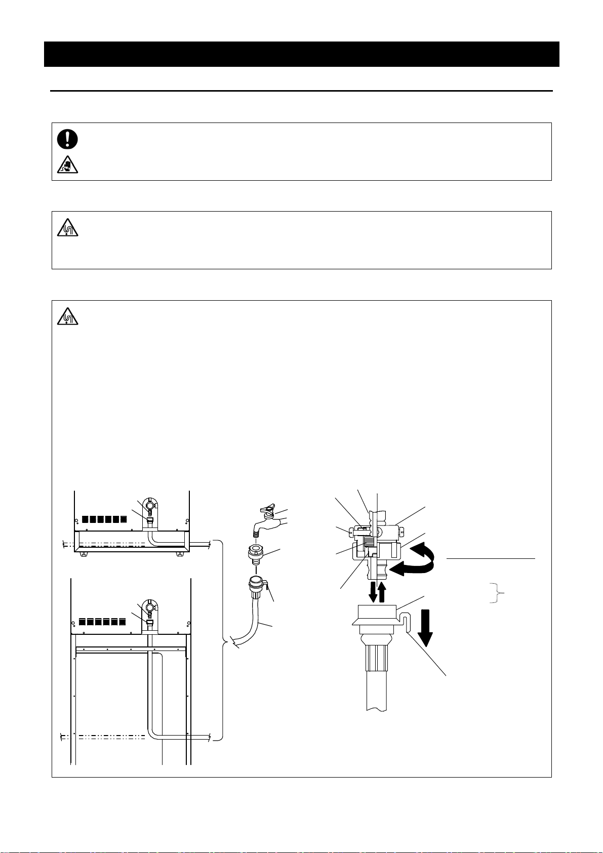
9. Connect the water supply hose securely
• If not connecting the water supply hose securely, the water supply hose or connection port
may be disconnected, resulting in water leakage such as water bursting forth.
• Take the connection port body and supply hose out of attachments to the unit. Install the unit
on a horizontal and stable place nearby tap and sink.
10. Connect the tap side
1. Slide the sleeve of socket ③ on connection port side in the arrow direction, then connection
port body and water supply hose can be separated. There separate the two parts.
2. Once loosen the plug ② from the ring ①.
3. Tighten the 4 mounting screws ⑤ uniformly while pressing the ring ① slightly and uniformly
to make the packing ⑥ in flat contact with water tap. If the tap is a chemical tap, adjust the
position so that the mounting screw is located at the bottom valley of tap nipple as shown.
4. Turn the plug ② clockwise to tighten securely. This will allow the tap and connection port to
be sealed by packing ⑥.
5. Insert the socket ③ securely to the plug ② with the sleeve slid in the arrow direction. The
sleeve returns to the original position when released, and then connection is completed.
In case that the socket is removed, the valve attached on the connection side of the main unit
stops the flow of water.
Water supply port
Sleeve on water
supply port
Water supply port
Sleeve on water
supply port
WG250
Tap
Connection
port body
Socket on
connection
port side
Water supply
hose
④
⑤
⑥
⑦
Before Using this unit
Tap
①
②
Connection Port Body
①Ring
②Plug
③
③Socket
④Spacer
⑤Mounting Screw
⑥Packing
⑦Filter
One-touch
Joint
Sleeve
Water supply hose
WG1000
6
Page 10

Before Using this unit
Requirements for Installation
11. Observe the specified pressure range of raw water from waterworks
• Apply the range of city water pressure between 0.5 X 100kPa and 5 X 100kPa (0.5 - 5kgf/cm2)
including nighttime.
• Range of raw water pressure is the same when "Water Supply Port Unit" (optional accessory)
is used.
12. Connection on body side
1. Remove the rubber cap from the water supply port plug
⑧.
2. Insert the socket ⑨ securely to the plug ⑧ on body
side with the sleeve slid in the arrow direction. The
sleeve returns to the original position when released,
and then connection is completed. The socket
contains a valve inside, which opens only when the
socket is connected by plug; otherwise, water is not fed
because this valve does not open.
Body side
⑧
⑨
13. Connect the water supply hose to the tap provided with sink equipment
• If the water supply hose is
connected to a tap without
sink equipment, flood damage
may be caused when water
supply hose is disconnected
or damaged; therefore be
sure to connect to a tap
having sink equipment.
Connection port Body
Sink
Tap
Socket on
connection
port side
Water supply hose
14. When the sink equipment is remote from water tap, use "Water Supply Port Unit"
(optional accessory)
• "Water Supply Port Unit" is designed to loosen the connection to the tap harder than the set of
standard water supply hoses when water pressure fluctuates.
15. In case that there is no tap
• In case that there is no tap, use appropriate joint shown in the optional "Coupler joints for feed
water".
7
Page 11

Requirements for Installation
16. Connect the drain hose securely
• If the drain hose is not connected securely, it may be disconnected, leaking water in the unit,
or leading to trouble of system.
1. Pick up the drain hose (with elbow) and the hose clamp from the main unit accessories.
2. Always make sure that the earth leakage breaker of the unit is "OFF".
3. Remove the rubber stopper from the outlet of the drain port hose on the main unit.
4. Push the hose clamp into the elbow of the drain hose, and next, put the elbow into the drain
outlet hose of the main unit, then tighten the hose clamp securely.
5. Pull the hose out from the drain hose-end outlet at right/left or backside of the main unit.
For WG1000 unit, be sure to set the hose in the hose holder at the backside plate.
Hose
clamp
Drain port hose
on the main un it
Before Using this unit
Hose holder
Elbow
Drain port
17. Use care in routing of drain hose
• Do avoid making bend or projection of drain hose.
• In case that the drain hose is bent and the drain cannot be performed, back-flow or breakage
of the cooling hose might occur.
• Place the drain hose lower than the drain port of this unit. Further, avoid piping which allows
paddle in the hose or at the hose outlet, because it is a resistance against drain.
• Place the end of drain hose where drain is allowed. When distilled water is being prepared,
cooling water is drained approx. 2 liters/min (approx. 2.6 liters/min in WG1000). Also drain
further increases when boiler water is drained, and sufficient drain equipment is required.
Drain hose (accessory)
WG250
Hose clamp
Drain hose
WG1000
8
Page 12

Before Using this unit
Requirements for Installation
18. Check the drain temperature of cooling water
• Drain temperature may exceed 60℃ in drainage from boiler. Drain to a place remote from
working environment not to be touched easily because there is a danger of burns.
• High-temperature cooling water could flow out. If vinyl chloride tube is used for the water
drain unit of the sink, such a tube could deteriorate. Water should be drained to a place away
from the drain tube of the sink. Even if VP tube (JIS K6741) is used for the vinyl chloride
tube, DV-RR joint is used for the joint, and even if insert socket (JIS K6739) is used, the water
drain trap in the nonstandard options should be used when the control temp. cannot be
lowered (60℃ or lower). Even if the drain temperature is 60℃ or lower, and if the
above-mentioned tubes and joint are not used, the drain trap in the nonstandard options
should be used.
19. When drain temperature of sink equipment does not fall under 60℃
• Use a drain trap (optional accessory).
• Drain trap makes temperature fall by accumulating cooled drain water temporarily. Further, it
mixes city water and cooled-down drain water, makes mixed water temperature fall, then lets
drain to sink equipment.
• Contact your dealer or Yamato Scientific sales office for detail of drain trap.
9
Page 13

Before Using this unit
Requirements for Installation
20. Install the ion exchange resin cartridge (CPC-S) securely
• Install the ion exchange resin cartridge (CPC-S) following the procedure shown below.
• Connect securely because insecure connection may cause water leakage.
1. Make sure that the earth leakage breaker of this unit is "Off" and that the tap is tightened.
2. Take the ion exchange resin cartridge out of attachments to the unit.
3. Place the ion exchange resin cartridge taken out on the receiver within the unit. (See Fig.1.)
4. Fix the ion exchange resin cartridge with the band of receiver. (See Fig.2.)
Fig.1
Fig.2
5. Remove the rubber cap attached to the inlet and outlet of ion exchange resin cartridge.
6. Fit in the coupler marked with (IN) to the inlet of ion exchange resin cartridge (left) until click is
heard. (See Fig.3.)
7. Fit in the coupler marked with (OUT) to the outlet of ion exchange resin cartridge (right) until
click is heard. (See Fig.3.)
Coupler may be hard at first. When applying force in inserting, do not make it curved because
insertion port may be broken.
Reset switch
T
U
O
N
I
IN
Fig.3
OUT
Fig.4
8. Coupler can be removed easily from the ion exchange resin cartridge by pulling it toward
yourself while pushing the black part of the coupler to the depth.
9. After changing, turn the breaker on and wait for about ten second, then press and hold the
reset switch till a beep is heard. (See Fig.4.)
10
Page 14

Requirements for Installation
21. Secure the pre-treatment cartridge securely
• Connect the hose in the body securely following the procedure shown below.
• Insecure connection may cause disconnection of connection hose, resulting in accident by
water leakage.
1. Make sure that the earth leakage breaker of this unit is "OFF" and that the tap is tightened.
2. Take the pre-treatment cartridge ① out of attachments to the body.
3. Inlet and outlet of the pre-treatment cartridge ① are provided with a cap, so remove it.
4. When the front door of this unit is opened, connection hose marked IN and OUT is found in
the coupler; there make connection matching them with IN and OUT on pre-treatment
cartridge ①.
5. In connecting, mate the coupler and port of cartridge while sliding the blue portion ③ of
coupler toward the hose, push in, then release the blue portion ③.
6. When connection is finished, place the pre-treatment cartridge at the position shown on the
right (near side on the left of distilled water tank) as paying attention to the bend of hose.
②
Before Using this unit
22. After installation
• This unit may topple over due to unexpected earthquake or shock causing injury. Take an
appropriate measure against toppling for safety.
(For WG1000, earthquake-resistant fittings are optionally available.)
①
Fig.6
Fig.5
11
Page 15

2. Before Using this unit
Requirements for Installation
22. Install the membrane filter firmly.
• Install the membrane filter as follows:
• Unless firm connection is made, water may leak from the threaded portion and may be mixed
into and contaminate the sampled pure water. Always ensure firm connection.
(1) Take out two membrane filters and seal tape from among accessories of the main
body.
(2) Pay attention to the direction of arrow mark on the membrane filter. Wind the
seal tape clockwise as viewed from the tape windind side two to three turns while
pulling the tape slightly. Remaining tape should be cut away.
(3) Screw the membrane filter, with the seal tape applied side on the top side, while
taking care not to crush threads. Check for water leak during sampling of pure
water. If any, screw the membrane filter further.
WARNING!
12
Page 16

p
p
p
Main Unit
WG250
Boiler
Heater
Heater
terminal block
Description and Function of Each Part
Distilled water tank
Reset switch
Drain cock
Leakage detection electrode
Pre-treatment cartridge
Control panel
Ion exchange resin cartridge (CPC-S)
Water sampling table
Earth leakage breaker
Drain port
(2pcs each at right/left)
Multi-purpose distilled water
sampling port
Product number sticker
Drain switch for
water sam
Distilled water
sam
ling port
Ion exchange water
sam
ling port
ling table
13
Page 17

p
r
Main Unit
WG1000
Description and Function of Each Part
Ion exchange resin cartridge (CPC-S)
Reset switch
Boiler
Heater
Water sampling table
Pre-treatment cartridge
Knurled Screw
Tank
Leakage detection electrode
Control panel
Earth leakage breaker
Leakage detection electrode
Product number
sticke
Drain switch for
water sam
Drain port
(2pcs each at right/left)
Multi-purpose distilled water
sampling port
14
ling table
Page 18

p
p
Description and Function of Each Part
Water Sampling Table and Multi-Purpose Distilled Water Sampling Port
Water sampling table
Use the water sampling table by pulling it out frontward. Because coolant for condenser is used, so
for draining the water in the following cases (and coolant is not flowed), press the drain switch
specifically used for the water sampling table at right side of the unit.
Coolant flows for one minute, and then, the water sampling table is drained. After that, returns to the
condition before pressing the switch.
① When the tank is filled to capacity (Distillation is not operated.)
② When drawing pure water
③ While standby time (the breaker is turned on, and POWER key is turned off.)
WG250
Drain switch for
water sampling table
Multi-purpose distilled
water sam
ling port
Water sampling table
WG1000
Drain switch for
water sampling table
Water sampling table
Multi-purpose distilled
water sam
ling port
Multi-purpose distilled water intake opening
The multi-purpose distilled water intake opening is located at right side surface of the unit, and
one-touch joint is installed at the opening. Distilled water in the tank can be filled by removing the plug
stopper, and connect the hard tube ofφ8 of outer diameter. Moreover, the one-touch joint is available
as connection port for optional goods.
Notice that distilled water pours when removing the plug stopper because the one-touch joint
does not have the check valve.
15
Page 19

Piping System View
Description and Function of Each Part
1 Pressure reduction valve 17 Boiler water supply solenoid valve
2 Pressure switch 18
3 Cooling water solenoid valve 19 Ion exchange water sampling solenoid valve
4 Raw water supply solenoid valve 20 Distilled water sampling solenoid valve
5 Pre-treatment cartridge 21 Ion exchange water flow sensor
Ion exchange resin cartridge (CPC-S)
6
(Two pieces are used for WG1000 type.)
7 Float cylinder 23 Ion exchange water sampling port
8 Float switch 1 24 Distilled water sampling port
9 Float switch 2
10 Boiler drain solenoid valve
11 Boiler drain cock
12 Boiler
13 Heater
Initial accumulated water drain
solenoid valve
22 Distilled water flow sensor
25
Distilled water tank
26
Float switch 3
27
Air filter
28
Distilled water sampling pump
29
Distilled water tank drain port
14 Condenser
15 Ion exchange water quality gauge electrode
16
Distilled water quality gauge electrode
16
30
Multi-purpose distilled water sampling port
31
Aspirator
32
Membrane filter
Page 20

Description and Function of Each Part
Principle of Operation
Description of the operation mechanism of WG250/1000 by each step.
1. Drain of the boiler
Turn on the earth leakage breaker and press POWER key. And after 15 seconds passed, boiler drain
solenoid valve (10) opens for approx. 40 seconds, and cooling water solenoid valve (3) opens for approx. 30
seconds at the same time. Drain of the boiler is performed every 5 hours during distillation.
2. Boiler Water Supply and Distilling Operation
When drain of the boiler is finished, both of raw water supply solenoid valve (4) and boiler water supply
solenoid valve (17) open at the same time in order to supply water to boiler (12). When float switch 1 (8) in
float cylinder (7) detects water level, heater (13) is turned on and distillation starts. With float switch 2 (9),
water supply to the boiler is controlled by opening/closing raw water supply solenoid valve (4) and boiler
water supply solenoid valve (17).
17
Page 21

Principle of Operation
3. Flow of Cooling Water
Description and Function of Each Part
During distillation, water is supplied and discharged in the order: (1) pressure-reducing valve, (3) cooling
water solenoid valve and condenser (14). When the distilled water tank is full, or when ion exchanged water
is sampled, distillation is stopped, and the cooling water is also stopped automatically.
4. Sampling of Distilled Water
For 10 minutes after starting distillation, initial distilled water condensed in condenser (14) is drained by
opening initial accumulated water drain solenoid valve (18). Then distilled water is stored in distilled water
tank (25) by distilled water quality gauge electrode (16). Distillation stops as the tank is full when float switch
3 (26) on the top in the tank operates. The stored water is collected by distilled water sampling pump (28)
through distilled water sampling solenoid valve (20), distilled water flow sensor (22), distilled water sampling
port (24), and membrane filter (32).
18
Page 22

Principle of Operation
5. Sampling Ion Exchanged Water
Description and Function of Each Part
Ion exchange water is sampled by way of the pressure-reducing valve (1), raw water supply solenoid valve
(4), pre-treatment cartridge (5), ion exchange resin cartridge (6), ion exchange water quality electrode (15),
ion exchange water sampling solenoid valve (19), ion exchange water flow sensor (21), ion exchange water
sampling port (23), and membrane filter (32).
19
Page 23

Control Panel
⑪
Description and Function of Each Part
①
⑩
MF
POWER
②
⑨
CONDUCTIVITY
⑧
⑦
MEASURED
CONTINUOUS
FILL
PURE
WATER
⑥
POWER key Turns on/off the power of the controller.
①
Message indication area Indicates the measured value and setting value.
②
WATER LEVEL lamp Indicates water level in the distilled water tank in five levels.
③
DITILLED WATER key Starts/stops drawing distilled water.
④
▲▼ key Selects the value setting item.
⑤
PURE WATER key Starts/stops drawing pure water.
⑥
FILL key Switches water collecting method. (Measured filling/Continuous filling)
⑦
FILL lamp Lights up when either of MEASURED or CONTINUOUS is selected.
⑧
CONDUCTIVITY key
⑨
M key
⑩
F key (Cancels the setting) then returns to the previous setting item.
⑪
Switches conductivity indication unit.(S/mΩ・m)
Used when entering submenu or maintenance mode.
Also (confirms the setting) then shifts to the next setting item.
WATER
LEVEL
FULL
EMPTY
DISTILLED
WATER
③
④
⑤
Description of ③ WATER LEVEL lamp
This lamp indicates the storage amount of distilled water in the tank in five levels. When this red lamp lights,
distilled water cannot be collected for empty drive prevention of the pump.
When this red lamp lights, distilled
water cannot be collected for empty drive prevention of the pump. When water keeps being stored, and a
red lamp in the lower is blinked, distilled water can be gathered. In addition, a red lamp in the lower is
turned off when the amount of storing water increases, a green lamp since the second step lamp, and the
amount of storing water can be confirmed.
<EMPTY> <FULL>
FULL
EMPTY
Lighting
Blinking
FULL
Lighting
EMPTY
Sampling pump operational range
FULL
EMPTY
20
FULL
Lighting
EMPTY
FULL
Lighting
EMPTY
FULL
Lighting
EMPTY
Page 24

Setup and Check before Use
Operation Method
WARNING!
1. Check of water supply
Check that the water supply hose is securely connected.
Open the tap.
Check that water does not leak from connection of water supply hose.
2. Check of drain
Check that the drain hose is securely connected.
Check that the drain hose is free from bend or projection.
When the drain hose is bent or the like, system does not operate normally, and in addition, it may
lead to water leakage accident. Inspect from time to time, and ensure that water is drained
properly.
3. Check of power supply
Check that the power cord is connected to appropriate plug socket.
4. Before operation
Turn on the earth leakage breaker, then, perform calibration before pressing POWER key.
Perform calibration operation at first-time using this unit (refer to page 22) and when changing the
heater of the boiler (refer to page 37).
Press POWER key while holding down PURE WATER key and DISTILLED WATER key.
Perform calibration operation (at the measured values of heater temperature and power-supply
voltage) for about five minutes, after then, distillation starts automatically. Key operation becomes
disable while calibration operation. In case that power failure occurs while calibration operation,
please perform calibration again.
5. Caution at initial operation
In sampling distilled water in initial energization and drain from distilled water storage tank, air is
contained in the pump and piping, and it takes time until sampling is started.
In sampling ion exchanged water immediately after changing pre-treatment cartridge or ion
exchange resin cartridge, it also takes time until sampling is started. Further, when each
cartridge is changed, drain about 5 liters in order to remove initial impurities.
21
Page 25

Operation Procedure
When operation is set up, follow the procedure below for operation:
1. Turning on power
When first-time using the unit, perform calibration
operation.
1. Turn on the earth leakage breaker.
2. Press POWER key while holding PURE WATER
key and DISTILLED WATER key.
3. After five minutes passed, distillation starts
automatically. (Clause 3)
From the second time using:
① Turn on the earth leakage breaker.
② Press POWER key.
MF
CONDUCTIVITY
MEASURED
CONTINUOUS
FILL
PURE
WATER
POWER
Yamato
Auto Still
WG250
2005/11/1 12:00
WATER
LEVEL
FULL
EMPTY
DISTILLED
WATER
②
Operation Method
② ②
2. Drain of the boiler
MF
Boiler Drainage
DW/DI Water
Not Available
CONDUCTIVITY
MEASURED
CONTINUOUS
FILL
PURE
WATER
3. Distillation operation
MF
In Distillation
Tank Empty
Distill-Water NA
Continuous
CONDUCTIVITY
MEASURED
CONTINUOUS
FILL
PURE
WATER
POWER
POWER
WATER
LEVEL
FULL
EMPTY
DISTILLED
WATER
WATER
LEVEL
FULL
EMPTY
DISTILLED
WATER
Drain of the boiler starts.
Drain of the boiler starts when turning on/off the earth
leakage breaker, and when five hours passed after
distillation starts. (Drain of the boiler does not start if
POWER key is not turned on.)
Distillation operation starts.
When there is no water in the tank, the left screen
display and the below screen display are alternately
indicated at 5 seconds interval. The value ・・・×
10-4S/m is indicated while initial distilled water is
drained (approx. 10 minutes), after that, the below
screen is displayed.
In Distillation
DW-Conductivity
Continuous
0.854×10
-4
S/m
It takes approx. 4 hours till the tank is filled at the water
collection available level. The above screen appears.
When the tank is full, the below screen appears.
DistillationStop
Tank Full
Continuous
22
Page 26

Sampling of Pure Water
Continuous collection of pure water
0.06×10
POWER
-4
S/m
MF
CONDUCTIVITY
MEASURED
CONTINUOUS
FILL
DI sampling
DIS-Conductivity
Continuous
WATER
LEVEL
FULL
EMPTY
Operation Method
PURE WATER lamp lights up by pressing
PURE WATER key while “CONTINUOUS” lamp
is ON. Then, pure water can be collected.
Collecting water stops by pressing PURE
WATER key again. Then, PURE WATER lamp
is turned on. After water collection is finished,
it returns to distillation operation.
PURE
WATER
DISTILLED
WATER
Continuous collection of distilled water
MF
CONDUCTIVITY
MEASURED
CONTINUOUS
FILL
PURE
WATER
DW sampling
Continuous
POWER
WATER
LEVEL
FULL
EMPTY
DISTILLED
WATER
DISTILLED WATER lamp lights up by pressing
DISTILLED WATER key while “CONTINUOUS”
lamp is ON. Then, distilled water can be
collected.
Collecting water stops by pressing DISTILLED
WATER key again. Then, DISTILLED WATER
lamp is turned on. After water collection is
finished, it returns to distillation operation.
23
Page 27

Collection of Measured Amount of Pure Water
1. Switching water collection method
Switch to “MEASURED” amount water collection
method.
Switch from “CONTINUOUS” to “MEASURED” by
pressing FILL key.
MF
DW-Conductivity
Measured: 0.1L
POWER
In Distillation
-4
0.85×10
S/m
Operation Method
CONDUCTIVITY
PURE
WATER
FILL
MEASURED
CONTINUOUS
WATER
LEVEL
FULL
EMPTY
DISTILLED
WATER
2. Amount of collecting water setting
0.85×10
POWER
-4
S/m
①
WATER
LEVEL
FULL
EMPTY
DISTILLED
WATER
MF
CONDUCTIVITY
MEASURED
CONTINUOUS
FILL
PURE
WATER
In Distillation
DW-Conductivity
Measured: 20.0L
Set the amount of collecting pure water. The same
setting screen is used for setting of pure water and
distilled water.
1. Set the amount of pure water by pressing ▲▼ key.
Set up to 30 liters for WG250, or up to 100 liters for
WG1000.
2. After setting, pressing PURE WATER key starts
water collection.
3. Collecting
MF
CONDUCTIVITY
MEASURED
CONTINUOUS
FILL
PURE
WATER
②
DI sampling
DIS-Conductivity
0.85×10
Measured: 18.2L
POWER
-4
S/m
WATER
LEVEL
FULL
EMPTY
DISTILLED
WATER
Water collection of measured amount starts.
1. The counter starts decrementing from the setting
value.
2. When collecting water is finished, message
"Measured: 0.0L" appears on the window.
3. Go back to clause 2.
If pressing PURE WATER key while collecting water,
the operation stops and the setting value is reset.
24
Page 28

Collection of Measured Amount of Distilled Water
1. Switching water collection method
Switch to “MEASURED” amount water collection
method.
Switch from “CONTINUOUS” to “MEASURED” by
pressing FILL key.
MF
DW-Conductivity
Measured: 0.1L
POWER
In Distillation
-4
0.85×10
S/m
Operation Method
CONDUCTIVITY
PURE
WATER
FILL
MEASURED
CONTINUOUS
WATER
LEVEL
FULL
EMPTY
DISTILLED
WATER
2. Amount of collecting water setting
0.85×10
POWER
-4
S/m
①
WATER
LEVEL
FULL
EMPTY
DISTILLED
WATER
MF
CONDUCTIVITY
MEASURED
CONTINUOUS
FILL
PURE
WATER
In Distillation
DW-Conductivity
Measured: 20.0L
Set the amount of collecting distilled water. The same
setting screen is used for setting of pure water and
distilled water.
1. Set the amount of distilled water by pressing ▲▼
key.
Set up to 30 liters for WG250, or up to 100 liters for
WG1000.
2. After setting, pressing DISTILLED WATER key
starts water collection.
3. Collecting
MF
CONDUCTIVITY
MEASURED
CONTINUOUS
FILL
PURE
WATER
POWER
DW sampling
DW-Conductivity
0.85×10
Measured: 18.2L
②
Water collection of measured amount starts.
1. The counter starts decrementing from the setting
value.
-4
S/m
2. When collecting water is finished, message
"Measured: 0.0L" appears on the window.
WATER
LEVEL
FULL
3. Go back to clause 2.
If pressing DISTILLED WATER key while collecting
EMPTY
DISTILLED
WATER
water, the operation stops and the setting value is
reset.
25
Page 29

Collection of Measured Amount of Distilled Water
In case that the tank becomes empty while collecting water
1. The left screen is displayed when the tank becomes
MF
CONDUCTIVITY
MEASURED
CONTINUOUS
FILL
PURE
WATER
POWER
In Distillation
Tank Empty
Distill-Water NA
Measured: 15.0L
WATER
LEVEL
FULL
EMPTY
DISTILLED
WATER
③
empty during collecting water, and DISTILLED
WATER lamp blinks and operation of water
collection is suspended.
2. Distillation starts.
3. In case that "EMPTY" lamp of WATER LEVEL
display does not light up, press DISTILLED WATER
key again to start collecting water. If PURE
WATER key is pressed under this condition, the
holding condition is released.
4. After collecting water is finished, "Measured: 0.0L"
appears on the window, and return to the screen of
Clause 2.
Operation Method
26
Page 30

Display of Water Quality
Switching conductivity unit
MF
CONDUCTIVITY
MEASURED
CONTINUOUS
FILL
PURE
WATER
DW-Conductivity
Continuous
POWER
DW sampling
0.85×10
-4
S/m
WATER
LEVEL
FULL
EMPTY
DISTILLED
WATER
Operation Method
Switch the conductivity unit.
Pressing CONDUCTIVITY key for 2 seconds switches
the conductivity unit.
Ex)
In case of switching the conductivity unit during
collecting distilled water
DW sampling
DW-Conductivity
Continuous
0.85×10
-4
S/m
DW sampling
DW-Resistivity
1.17×10
Continuous
4
Ω・m
Switching conductivity display
MF
CONDUCTIVITY
MEASURED
CONTINUOUS
FILL
PURE
WATER
DW-Conductivity
Continuous
POWER
DW sampling
0.85×10
-4
S/m
WATER
LEVEL
FULL
EMPTY
DISTILLED
WATER
Switch the conductivity display. The conductivity of
distilled water is displayed during distillation, and the
conductivity of pure water is displayed during collecting
pure water.
Pressing CONDUCTIVITY key switches the
conductivity display for either of pure water or distilled
water.
Ex)
In case that you want to see the conductivity of pure
water during collecting distilled water: In case that
the conductivity of pure water
DW sampling
DW-Conductivity
Continuous
0.85×10
-4
S/m
DW sampling
DIS-Conductivity
Continuous
0.06×10
-4
S/m
If not pressing any keys, the conductivity display is
returned.
27
Page 31

Operation Method
Display of Water Quality
Measurement of Electric Conductivity
The water conductivity meter on the control panel displays the conductivity at the outlets of the
ion-exchange resin cartridge and the condenser for distilled water. The displayed value can be used
as an index for replacing the ion-exchange resin cartridge. The value of conductivity is valid only
when the electrode is fully damped with water, or when pure water is dripped. Correct value is not
displayed in the following cases because the electrode is not damped or air bubbles are produced.
1. At beginning of operation and during halts
2. Just after changing pretreatment cartridge or ion-exchange resin cartridge
3. Just after distillation starts
Electric conductivity
Electric conductivity is a value indicating easiness of flowing of electricity. In the case of water,
electricity flows the more easily when the more electrolyte i.e. impurity is solved, so the value of
conductivity is the greater; when the less electrolyte is solved, the smaller is the value.
When the value of electric conductivity is the smaller, the better is purity of pure water.
Here, electric conductivity indicates only electrolyte, and does not indicate content of
non-electrolyte (such as organic substance, colloid substance, dissolved gas, and microorganism),
and it is just an index indicating purity of pure water, and it does not represent all of purity.
Specific resistivity indicates the same contents as electric conductivity. Specific resistivity is
inversely related to electric conductivity, and when the value is the greater, the better is purity.
When obtaining specific resistivity from electric conductivity, where specific resistivity is R and
electric conductivityρ,
R[Ω・m]
So the theoretical value of pure water is as follows:
R=18.3×10
(Take notice that the resistivity is displayed in integer form (not in decimal) in the range 18 to 1 x
104Ω・m.)
ρ=0.055×10
=
4
Ω・m (18.3MΩ・cm) 25℃
-4
1
ρ
[/
S m]
S/m (0.055μS/cm) 25℃
or R[×10 Ω・m]
4
=
×10 S m]
ρ
1
[/
-4
Quality of ion exchange water and distilled water
Ion exchange water and distilled water have the following features respectively. Distinguish them
as necessary in use.
It is ideal to use pure water immediately after sampling; therefore be sure to drain water in distilled
water tank if it is out of use for a long time. If water has been stored in distilled water tank for a long
time, drain once, then store in distilled water tank newly before use.
1. Ion exchange water
Most of electrolyte in water is removed, and water with the lowest electric conductivity is obtained.
However, non-electrolyte cannot be removed. In addition, slight fall of purity is found while resin is
new and when water is fed again after halt of system.
2. Distilled water
Electrolyte and non-electrolyte can be removed in average except for low boiling point substance
such as ammonia. However, carbon dioxide gas in the atmosphere is absorbed and carbon oxide
is generated in the process of manufacturing (condensing/storing), and so the electric conductivity
is worse than ion exchange water, that is 1 to 2.5 X 10⁻⁴ S/m (1 to 2.5 μS/cm) at 25C, and
represents weak acid (pH5 to 6).
See "2 - Common item (11) Water" of JIS K0102 (Plant drain test procedure) for removal of
dissolved gas (oxygen and carbon dioxide) in pure water.
28
Page 32

Setting/Display of Submenu
1. Setting/display of submenu
Operation Method
POWER
WATER
LEVEL
FULL
EMPTY
DISTILLED
WATER
①,③
PURE
WATER
MF
CONDUCTIVITY
MEASURED
CONTINUOUS
FILL
Sub-Menu
1.Buzzer
③
2.Calendar
3.EXCH History
②
2. Setting/display of each item
2.1. Setting of ON/OFF of buzzer sound
Buzzer
1. Key Click
2. Error Buzz
Perform setting/display of submenu.
1. Pressing M key for 2 seconds displays the submenu.
2. Select the item to be set or displayed by pressing ▲▼
key.
3. Pressing M key confirms the setting and shifts to the
selection screen.
Press F key to (cancel the setting and) return the previous
setting screen.
If not pressing any keys for 2 minutes, the screen returns to
the previous display before setting/display of submenu.
Items of submenu are:
1) ON/OFF of buzzer sound
2) Calendar setting
3) Consumables change history
4) Maintenance history
5) Error occurrence history
6) Power failure occurrence history
7) Water cutoff occurrence history
8) Language selection
9) Power failure recovery function
To set a key clicking sound/alarm buzzer sound:
1. Select an item of submenu by pressing ▲▼ key.
2. Confirm the item by pressing M key. The selection
screen appears.
3. Specify "ON" or "OFF" of each item by pressing ▲▼
key, and confirm the setting by pressing M key.
4. Pressing F key returns to the submenu screen.
"ON" is set to buzzer sound at default setting.
2.2. Calendar setting
Calendar
2005 year
9/29 month/day
12:25 h:min
2.3. Consumables change history
Buzzer
1. Hollow Filter
2. Ion-Exchange-S
3. DW M-Filter
4. 6.DI M-Filter
To set the calendar:
1. Set the items (year/month/day/hour/minute)by pressing
▲▼ key.
2. Confirm the setting by pressing M key.
3. The set items are displayed. Check the set items and
confirm your entry by pressing M key to go to the
selection screen.
4. Pressing F key returns to the previous submenu screen.
To display the history of changing pretreatment filter,
ion-exchange resin (S), M filter for distilled water, and M
filter for pure water:
1. Display an item of submenu by pressing ▲▼ key.
2. Confirm the setting by pressing M key. The history
display appears.
3. Confirm the history by pressing ▲▼ key.
4. Pressing F key returns to the previous screen.
Up to 20 records are displayed for each change history. If it
exceeds 20 records, the oldest record is deleted.
29
Page 33

Setting/Display of Submenu
2.4. Maintenance history
Maintenance
History No.1
2005/09/29 12:25
Operation Method
To display the maintenance history:
1. Confirm the maintenance history by pressing ▲▼ key.
2. Pressing F key returns to the previous screen.
Up to 20 records are displayed for each change history. If it
exceeds 20 records, the oldest record is deleted.
2.5. Error occurrence history
Error History
History No.1
Leak error
2005/09/29 12:25
2.6. Power failure occurrence history
Outage History
History No.1
↓05/09/29 12:25
↑05/09/29 12:30
2.7. Water cutoff occurrence history
Water Alarm
History No.1
↓05/09/29 12:25
↑05/09/29 12:30
2.8. Language selection
Language
1. Japanese
2. English
To display the error occurrence history:
1. Confirm the maintenance history by pressing ▲▼ key.
2. Pressing F key returns to the previous screen.
Up to 20 records are displayed for each change history. If it
exceeds 20 records, the oldest record is deleted.
For details of error alarms, refer to page 42.
To display the power failure occurrence history:
1. Confirm the maintenance history by pressing ▲▼ key.
2. Pressing F key returns to the previous screen.
Up to 20 records are displayed for each change history. If it
exceeds 20 records, the oldest record is deleted.
To display the water cutoff occurrence history:
1. Confirm the maintenance history by pressing ▲▼ key.
2. Pressing F key returns to the previous screen.
Up to 20 records are displayed for each change history. If it
exceeds 20 records, the oldest record is deleted.
To select display language:
1. Select an item of submenu by pressing ▲▼ key.
2. Confirm the item by pressing M key. The submenu
screen appears.
2.9. Power failure recovery function
Resume Function
1. No
2. Yes
3. Finishing of setting/display
Press M key for 2 seconds.
To set the power failure recovery:
1. Select an item of submenu by pressing ▲▼ key.
2. Confirm the item by pressing M key. The submenu
screen appears.
This function is set to "invalid" at default setting.
The screen returns to the previous display before
setting/display submenu.
30
Page 34

Handling Precautions
WARNING!
If a problem occurs
If smoke or strange odor should come out of this unit for some reason, turn off the power key
right away, and then turn off the circuit breaker and the main power. Immediately contact a
service technician for inspection. If this procedure is not followed, fire or electrical shock may
result. Never perform repair work yourself, since it is dangerous and not recommended.
During a thunder storm
During a thunderstorm, turn off the power key immediately, then turn off the circuit breaker and
the main power. If this procedure is not followed, fire or electrical shock may be caused.
Take enough care in handling detergent (liquid)
• In storing detergent (liquid), store in enclosable container avoiding high temperature and
humidity.
• Principal component of detergent (liquid) Orgazor 10 is sulfamic acid (acidic with pH of water
solution approx. 1).
• In handling this detergent (liquid), use protective tools (gloves, mask, and glasses).
• When it is in contact with human body, wash it away with clean water.
• Neutralize the liquid with neutralizer (such as sodium hydroxide) after washing.
• Ensure neutralization with pH test paper, etc.
• Do not use empty container for beverage.
• Do not allow detergent to directly flow into agricultural irrigation canal or fields because it
causes withering of rice crop.
Do not step on this unit
Do not step on this unit. It will cause injury if this unit fall down or break.
Do not put anything on this unit
Do not put anything on this unit. It will cause injury if fall.
In power failure (In case that the unit does not power failure recovery function)
When system has halted during operation due to power failure etc. and is provided with power
again, system is brought to standby status. When restarting operation, start from (Page 22 "1.
Turning on power").
31
Page 35

Maintenance Method
Daily Inspection and Maintenance
Timing of maintenance and inspection
(Perform daily inspection for stable use of product.)
Maintenance/check items Reference for timing Remarks
Throughput: About 5000 liters of city water
Replacement of
pre-treatment cartridge
Replacement of
membrane filter
Replacement of ion exchange
resin cartridge
Cleaning of distiller 3 months
Cleaning of water supply
hose filer
Replacement of hose 2 years Connections shall be checked monthly.
Drainage of distilled water tank 3 months
Approx. 6 months
Exchange message appears
on the indication area.
Approx. 3 months
Exchange message appears
on the indication area.
Exchange message appears
on the indication area.
(Displayed when the
conductivity of pure water is
more than 1 x 10
6 months
-4
S/m.)
in Tokyo.
If the quality of raw water is not good,
perform this maintenance as soon as
possible.
Throughput: approx. 500 liters for pure
water.
Need to exchange if the amount of collection
is less than the above value.
Throughput: About 700 liters of the raw
water of 200 x 10
WG1000 type)
If the quality of raw water is not good, start
the operation as soon as possible.
If not used for a long time, drain water from
the tank.
-4
S/m. (1400 liter for
Replacement of pre-treatment cartridge
See Page 11 "21. Secure the pre-treatment cartridge securely" for replacement procedure.
When the cartridge is put to use without replacement, life span of ion exchange resin cartridge
becomes short.
Please dispose used cartridge as nonconbustibles. When it is sent back to our company, fill in the
designated invoice attached to a new cartridge, and send it with the used cartridge to us.
Replacement of ion exchange resin cartridge
When a cartridge is stored for a long time, deterioration of water quality and fall of processing
capacity are found; therefore prepare a spare cartridge in a planned manner for replacement
timing. Standard for storage is about 4 months.
In replacement, see Page 10 "20. Install the ion exchange resin cartridge (CPC-S) securely".
When a cartridge is used without replacement, much scale is deposited on boiler and heater,
which causes decrease of distilled water sampling and damage to heater.
Please dispose used cartridge as nonconbustibles. When it is sent back to our company, fill in the
designated invoice attached to a new cartridge, and send it with the used cartridge to us.
We promote the reasonable disposal, collection, and recycling of cartridge for environmental
protection.
※ After changing the pretreatment cartridge, the membrane filter, or the ion-exchange resin cartridge,
press and hold the reset switch at backside of the door for two seconds till a beep is heard. Then the
warning indication is reset and the change record is registered in the consumables change history.
In case that two or more items are changed at the same time, they are registered in the consumables
change history in order of occurrence. However, be sure that the ion-exchange resin cartridge is
normally registered at the last. (Warning alarm for the ion-exchange resin cartridge is automatically
recovered.)
32
Page 36

Maintenance Method
Washing of Distiller
Dismounting of Distiller
1. Turn "OFF" the earth leakage breaker of the unit.
2. Close the tap.
3. Check that the boiler is not hot (longer than 30 minutes after the breaker is turned "OFF"), then open
the front door of the unit, and open the boiler water drain cock.
4. Disconnect the hose connected to the boiler ① and condenser ②. In disconnecting from the
distilled water outlet and boiler water supply and drain port, turn the hose band by use of tool and
displace the engaged portion (serrated portion). Take care in disconnecting because excessive
force applied to glass may cause damage.
②
Cooling Water
Outlet
Boiler Water Supply and
Drain Port
Cooling Water
Inlet
Distilled
Water
Outlet
①
5. Disconnect the hole plug at left plate, remove four screws with a screw driver, then remove the left
plate.
6. Loosen 4 screws on the right of terminal block located at the right top of the body frame with left side
plate dismounted by use of Phillips screwdriver, and disconnect the heater lead terminal.
(For WG1000, 8 pieces of screw are used because it has two heaters.)
33
Page 37

Maintenance Method
Washing of Distiller
7.
1) Disconnect the heater lead wire from grommet.
Note that, do not bend or pull the heater lead wire more than necessary.
2) Remove the two screws of boiler securing band with a Phillips screwdriver, and take the boiler
and condenser out of the body.
Grommet
3) Loosen the knurled screws (three) and remove the boiler and condenser.
Grommet
Condenser
Connecting
Hardware
Connection Port
with Condenser
Packing
Boiler
Washing of boiler
1. Adjust detergent liquid.
1) Prepare approx. 2 liters of hot water at 50 to 60°C.
2) Add attached scale detergent (Orgazor) approx. 200g to hot water prepared in 1) and agitate well.
2. Seal the hose connection port at the bottom of boiler (boiler supply and drain port) by use of rubber
stopper, etc.
3. Secure the boiler at a stable position to prevent washing liquid from spilling.
4. Pour in washing liquid through connection port with condenser with heater turned on.
Most scale is removed in 4 to 5 hours approximately. Drain washing liquid in the boiler. If much scale
is distiller deposited, pour in washing liquid newly, and repeat washing
1) When scale-removing work is finished, take the heater out of boiler and wash each of them
enough with city water. Here, in washing the heater with water, be sure to fill a larger beaker with
water and wash the heater inside so that lead wire and its routing port are not wet by water.
Avoid washing the heater directly with water from tap.
2) If solid scale distiller remains after washing by washing liquid, follow the remedy below:
Boiler: Scrub with brush etc. for removing.
Heater: Scrub with something soft such as wood piece or plastic.
In this connection, remove scale on the heater uniformly in general, never leaving solid scale in part. In
an extreme case, only such part has a great heat resistance, causing damage to the heater.
34
Page 38

Maintenance Method
Washing of Distiller
Washing of Condenser
1. Pour detergent liquid into the cooling pipe of condenser.
(See Page 34 "Washing of boiler" for formulating detergent liquid.)
Detergent
Liquid
Hose
Connection
Port
2. If detergent liquid should flow out of hose connection port, seal with rubber stopper. Most fur can
be removed in 4 - 5 hours approximately.
3. Drain detergent liquid, and then wash enough with city water.
Handling of Detergent Liquid (also refer to Page 31 "Handling Precautions")
1. Wash the boiler and heater sooner. If the more scale is deposited, the more difficult is its removal,
which may cause decrease of distilled water sampling and damage to heater.
2. When washing is finished, drain detergent liquid out of the unit, and apply neutralization by
neutralizer (such as sodium hydroxide). In neutralization, check that it is neutral by use of pH test
paper, etc. (Principal component of scale detergent: Sulfamic acid and pH of water solution: Acidic
approximately 1)
3. In storing this detergent, seal the agent and store in cold and dark place avoiding high temperature
and humidity.
4. In handling this detergent, be sure to use protective tools (gloves, mask, and glasses).
5. When it is in contact with human body, wash it away with clean water.
6. Do not use empty container for beverage.
7. Do not allow detergent to directly flow into agricultural irrigation canal or fields because it causes
withering of rice crop.
Installation of boiler
1. Secure the boiler with the boiler securing band so that connection port of condenser is horizontal.
Check that the packing is contained in the cap nut, and then install the heater into the boiler with
letters "YK-W-3" faced up.
Connection Port with
Condenser
Packing
YK-W-3
Heater
Cap Nut
Boiler Securing
Band
35
Page 39

r
Maintenance Method
Washing of Distiller
2. Attach 4 heater lead terminals to the terminal block.
Heater Lead
(wire diameter, thick)
Heater Lead
(wire diameter, thin)
3. Install the left side plate on the body.
4. Insert the hose to the boiler water supply and drain port, and secure with the hose band.
Installation of condenser
1. Place packing in the connection port of boiler with condenser, and secure with connecting hardware
so that the boiler and condenser are placed in the same direction.
Inlet Outlet
Boiler
Condenser
Connecting
Hardware
View from above
2. Connect the hose respectively to the cooling water inlet, outlet, and distilled water outlet of
condenser.
3. Close the boiler water drain cock.
Boiler Wate
Drain Cock
Open
Close
36
Page 40

Maintenance Method
Replacement of Heater
• If the heater should be disconnected or damaged due to deposit of scale, replace it by the
procedure below. (Also refer to Page 33 "Washing of Distiller" in working.)
1. Turn "OFF" the earth leakage breaker of this unit.
2. Close the tap.
3. Turn "OFF" earth leakage breaker, and when more than 30 minutes has passed, open the front door
of this unit, and open the boiler water drain cock.
4. Open the left side plate of the body, loosen the four screws on the right of the terminal block, and
disconnect the heater lead terminal.
5. Pull the heater lead out of the grommet.
6. Remove the cap nut of heater, and pull out the heater.
7. Remove the packing and cap nut from the damaged heater.
8. Install the packing and cap nut on the new heater. At that time, do not touch with bare hand in order
to prevent soiling by hand.
Packing
9. Install on the boiler so that "YK-W-3" mark of the heater is faced up.
10. Feed the heater lead wire through the grommet, check the heater lead wire attaching position, and
secure to the terminal block.
11. Mount the left side plate.
12. Close the boiler water drain cock.
13. Close the front door, and then open the tap.
14. Turn on the earth leakage breaker.
15. The standby screen appears at the display window of the control panel.
16. Perform calibrations by pressing POWER key while holding down PURE WATER key and
DISTILLED WATER key. (Refer to page 21.)
(Calibration is performed for storing the standard temperature of the sensors in each heater under
normal operation in the inner controller. Performing calibration detects errors when the temperature
rises higher than the standard temperature + 20℃.)
17. During calibration, a message is displayed at the message window of the control panel.
18. After approx. 5 minutes passed after starting calibration, normal operation starts automatically.
37
Page 41

Washing of Water Supply Hose Filter
1. After turning off the earth leakage breaker
on this unit, turn the tap off, slide the
sleeve to the direction of the arrow, then,
remove the water supply hose from the
connection port.
2. Remove the plug ② from ring ① as
turning.
3. Cleanse filter ⑦ attached to the packing
with water.
4. Wash the filter with spray, etc.
5. Assemble by reversing the procedure.
Tap
④
⑤
⑥
⑦
Water
Supply
Hose
Maintenance Method
①
②
Connection Port Body
①Ring
③
Sleeve
②Plug
③Socket
④Spacer
⑤Mounting Screw
⑥Packing
⑦Filter
One-touch
Joint
Tap side
Replacement of Hose
• Be sure to use a hose specified by Yamato Scientific for replacement.
38
Page 42

Long storage and disposal
When not using this unit for long term / When disposing
• If this unit is to be put out of service for a long time, be sure to turn of the earth leakage
breaker of this unit for safety, and close the tap. Water in the boiler and distilled water tank, if
stored as it is, will deteriorate in quality due to generated bacteria or algae. Drain water by
the procedure below:
Boiler Water Drain
1. In draining boiler water, turn off the earth
leakage breaker, ensure that the tap is
closed, then wait for 30 minutes or more,
and open the front door.
2. Open the boiler water drain cock.
3. Make sure that all water in the boiler and
float cylinder is drained.
4. Be sure to close the boiler water drain
cock. If boiler water drain cock is opened
in next use, water is not fed into the boiler,
and distillation is not started.
Open
Boiler Water
Close
39
Page 43

Long storage and disposal
When not using this unit for long term / When disposing
WARNING!
When disposing…
• Keep out of reach of children.
• Treat as large trash.
When the unit is out of service at night and on holidays
• Turn off the earth leakage breaker.
• Be sure to close the tap.
• Fluctuation of city water pressure may cause unexpected accident such as water leakage.
• In use in winter at a severely cold place, beware of freezing in the tank, boiler, condenser, etc.
while system is stopped.
Environmental protection should be considered
We request you to disassemble this unit as possible and recycle the reusable parts considering to the
environmental protection. The feature components of this unit and materials used are listed below.
Component Name Material
Main components of exterior
Exterior Made of iron, bonded steel plate, melamine resin baking finish
Exterior rear plate Made of iron, bonded steel plate, melamine resin baking finish
Door Made of iron, bonded steel plate, melamine resin baking finish
Door rear plate Stainless steel plate SUS 304
Mounting plate (painted) Made of iron, bonded steel plate, melamine resin baking finish
Mounting plate (unpainted) Stainless steel plate SUS 304
Electric parts mounting plate Aluminum
Hinge Stainless steel plate SUS
Rubber foot Synthetic rubber
Mounting tabs Stainless steel plate SUS 304
Production plates Polyester
Main components of water circuit system
Boiler Hard glass
Condenser Hard glass
Float cylinder Polypropylene
Pure water tank Polyethylene
Drain port Polypropylene
Float cylinder branch pipe Polypropylene
Electrode holder Polypropylene
Water sampling port Polypropylene
Control panel ABS resin
Water sampling table ABS resin
40
Page 44

Long storage and disposal
When not using this unit for long term / When disposing
Component Name Material
Main components of water circuit system
Resin cylinder case Polypropylene
Ion exchange resin Polystyrene Resin
Water quality gauge electrode Titanium
Heater Ceramic
Heater mounting nut Teflon
Main components of piping system
Water supply hose Vinyl chloride
Drain hose Ethylene propyne
Hose (transparent) Vinyl
Hose (milky transparent) Silicon
Hose clamp Polyacetal
Hose nipple (resin black) Polyamide
Hose nipple (resin white) Polypropylene
Hose nipple (metal) Brass
Main components of electric system
Casing: Polypropylene
Impeller: Polypropylene
Pump
Solenoid Valve
Float Switch Polypropylene
Power Cord, Wiring Material, etc. Wiring material and board coated by synthetic rubber and resin
Magnet: Ferrite magnet
Motor case: Iron
Rotor: Iron
Made of metal: Body, brass
Made of resin: Body, polyacetal
41
Page 45

Failure indication and Its Contents
Alarm Indication Condition Corrective measures
In the Event of Failure…
Water cutoff alarm
Pretreatment filter
exchange notification
Ion-exchange resin S
exchange notification
Membrane filter for
distilled water
exchange notification
Feed Water Alarm
Check
Flow & Pressure
It's time
to exchange
Hollow Filter
Water Quality NG
It's time
to exchange
Ion-EXCH Resin-S
Distilled Water
Membrane Filter
It's time
to exchange
When raw water pressure
decreases (<0.5kg f/cm
when water cutoff occurs
When 6 months passed
under continuous energizing
condition
When the conductivity of
pure water exceeds 1×10
S/m
When 3 months passed
under continuous energizing
condition
2
), or
-4
Check raw water.
Change the pretreatment
filter.
Press and hold the reset
switch on backside of the
door till a beep is heard.
Then, the alarm indication
is reset.
Change the ion-exchange
resin.
Press and hold the reset
switch on backside of the
door till a beep is heard.
Then, the alarm indication
is reset.
Change the membrane
filter for distilled water.
Press and hold the reset
switch on backside of the
door till a beep is heard.
Then, the alarm indication
is reset.
Membrane filter for
pure water exchange
notification
Maintenance time
notification
It's time
to exchange
Ion-EXCH Water
Membrane Filter
to maintenance
It's time
Service Call
Change the membrane
filter for pure water.
When 3 months passed
under continuous energizing
condition
When 3 years passed under
continuous energizing
condition
Press and hold the reset
switch on backside of the
door till a beep is heard.
Then, the alarm indication
is reset.
Perform maintenance of
the unit.
Press and hold the reset
switch on backside of the
door till a beep is heard.
Then, the alarm indication
is reset.
42
Page 46

Failure indication and Its Contents
Error Indication Cause Symptom Countermeasure
In the Event of Failure…
Controller error
Water leakage
error
Overheat of
heater
Burnout of
heater
Controller Error
Service Call
Leak Error
Service Call
Over Heat Error
Service Call
Heater Error
Service Call
When the setting value
which is memorized in the
memory chip cannot be
read properly, or when an
abnormal value is
displayed
When the resistance
value of the water leakage
sensor input becomes
less than the water
leakage error judgment
value
When temperature at the
heater excesses the error
judgment value, or when
breakage or shortage
occurs on the temperature
sensor
When temperature of the
heater did not rise after
certain time passed
during distillation
All controls
of the heater
and solenoid
valve are
turned OFF.
Turn the breaker on
again. If the trouble
persists, please call
our customer
service center.
Turn the breaker off
and check the
piping parts. For
details, refer to page
45.
Change the heater.
Change the heater.
Tank water level
meter error
Pure water
conductivity
meter (S) error
Distilled water
conductivity
meter error
Tank Water
Sensor Error
Service Call
Ion-Exchange-S
Sensor Error
Service Call
Distilled Water
Sensor Error
Service Call
When the condition of
the float contacting points
in the tank water level
meter becomes abnormal
When the state of
breakage or shortage of
the thermistor sensor for
pure water conductivity
gauge continues longer
than error judgment time
When the state of
breakage or shortage of
the thermistor sensor for
distilled water conductivity
gauge continues longer
than error judgment time
Change the float
switch.
Change the pure
water conductivity
sensor.
Change the distilled
water conductivity
sensor.
43
Page 47

In the Event of Failure…
Failure indication and Its Contents
Others Indication Cause Symptom Countermeasure
Boiler drain
error
Coolant error
Water level error
of boiler
Water level
meter of boiler
error
Boiler Water
Waste Error
Service Call
A Coolant Error
Service Call
Boiler Water
Level Error
Service Call
Boiler Water
Sensor Error
Service Call
When the heater
operation water level input
kept OFF even if the time
for required to evaluate
the boiler water level error
passed after starting
water supply to the boiler
When the state that
became boiler water
overflow input ON in the
float pipe continued
longer than coolant error
judgment time
When the heater
operation water level input
kept OFF even if the time
for required to evaluate
the boiler water level error
passed after starting
water supply to the boiler
When the condition of the
float contacting points in
the float pipe becomes
abnormal
All controls
of the heater
and solenoid
valve are
turned OFF.
Check the solenoid
valve for drain and
drain path.
Check the coolant
solenoid valve and
the coolant path.
Check the
feedwater solenoid
valve and feedwater
path whether
manual drain cock is
opened or not.
Change the float
switch.
• When an error occurs, confirm the error message shown at the message window, and call the shop from which you
made a purchase or our customer support center.
44
Page 48

In the Event of Failure…
Remedy for Trouble
Countermeasure against water leakage error
1. Turn off the earth leakage breaker at left surface of the main unit.
2. After repairing the defective area, wipe water off at the bottom in the unit, and dry thoroughly for
re-starting the operation.
3. If the electrode is removed, make sure to reinstall it.
4. Close the door.
5. Turn on the earth breaker, and press POWER key. Now the defect is repaired, and the unit starts
normal operation.
<How to remove the lower front panel of WG250>
1. Remove the screws at left/right positions of the lower front panel.
2. Pull the panel frontward. Be careful of the cable of the drain switch specially used for water sampling
table.
3. Disconnect the cable of the drain switch for water sampling table. Then, remove the lower front panel.
For installation, perform the above steps in reverse order (from 3 to 1).
WG250
Water leakage detection electrode
45
WG1000
Page 49

Trouble Shooting
Condition Check the following
Water is not supplied.
In the Event of Failure…
• Defect of raw water supply solenoid valve.
• Insufficient city water pressure or water failure.
• Defect of pressure switch.
• Clogging of pre-treatment cartridge.
Water supply does not stop.
No water is supplied to boiler.
Heater does not turn on.
Cooling water does not flow.
The initial accumulated water is
not drained.
Distilled water is not accumulated.
Distilled water is not stored.
Water is not sampled.
• Defect of float switch.
• Defect of raw water supply solenoid valve.
• Defect of boiler water supply solenoid valve.
• Defect of float switch.
• Clogging of pre-treatment cartridge.
• Opened boiler water drain cock.
• Defect of float switch.
• Break in heater.
• Defect of cooling water solenoid valve.
• Initial boiled water is not drained.
• Defect of initial boiled water drain solenoid valve.
• Defect of piping.
• Defect of float switch.
• Defect of Ion exchanged water/Distilled water sampling
solenoid valve.
• Defect of distilled water sampling pipe.
• Defect of piping.
Measures in emergency
Error indications/causes
This unit has a self-diagnosis function. When a trouble occurs during operation, or when a failure
occurs on the unit, an error message is displayed on the control panel. Turn off the earth leakage
breaker when an alarm occurs, close the tap.
For details of error indications, refer to "Failure indication and Its Contents (page 42)".
Measures
When the following error signs appear, memorize the sign and turn the tap off immediately. If an error
occurs, part change or unit check becomes required. Please call the shop from which you made a
purchase or our customer support center. In that case, please notify them of the error sign.
46
Page 50

After Service and Warranty
In Case of Request for Repair
If the failure occurs, stop the operation, turn OFF the power switch, and unplug the power plug.
Please contact the sales agency that this unit was purchased, or the Yamato Scientific's sales office.
< Check following items before contact >
◆ Model Name of Product
◆ Production Number
◆ Purchase Date
◆ About Trouble (in detail as possible)
Minimum Retention Period of Performance Parts for Repair
The minimum retention period of performance parts for repair of this unit is 7 years after
discontinuance of this unit.
The "performance part for repair" is the part that is required to maintain this unit.
See the production plate attached to this unit.
47
Page 51

Specification
Model WG250 WG1000
Feedwater method One-touch coupler connecting resin hose/free hose connecting
Drain method Left/right selection connecting method/hose connecting
Purified water Distilled water/Ion exchange water
Production of distilled water
Collection of distilled water
Collection of ion exchange
water
Performance
Setting range of capacity
(Continuous water collection)
Condenser Super hard glass
Heater Ceramic heater 1.4kw Ceramic heater 1.9kw
Raw water side filter
Ion exchange resin cartridge
Membrane filter
Water leakage detection
Distilled water storage tank
Configuration
Water leakage detector forcefully shut off the feedwater solenoid valve
Water sampling table
Multi-purpose distilled water
sampling port
Water level detection Lead switch, Five level detection (also used for distillation control function)
Raw water pressure range
Ambient temp.
Power supply (50/60 Hz) 100V AC 15A 200V AC 20A
External dimension
Standard
(Width X Depth X Height)
(*2)
Weight Approx.55 kg Approx.105 kg
Approx. 1.8 λ/h Approx. 5 λ/h
0.5 to 1.0 λ/min
0.5 to 1.0 λ/min
0.1 to 2 λ
0.1 to 90 λ
(Continuous water collection)
Pre-treatment cartridge (PWF-1),
Activated carbon + Hollow yarn film 0.1μm
CPC-S (2λ×2types)×1 CPC-S (2λ×2types)×2
0.1μm×2
when water leakage is detected.
Made of polyethylene, 30λ Made of polyethylene, 100λ
Slide-out type
Load-bearing capacity:10kg
For 5λ beaker with handle
Load-bearing capacity:20kg
Slide-out type
For 10λ tank
Feedwater connection to WR type: at right side of main unit
2
0.5×100 kPa to 5×100 kPa (0.5 to 5 kgf/cm
)
5℃~35℃
(*1)
600×660×780 mm 600×660×1650 mm
• Water supply hose, drain hose, and connection assembly (1):
1 respectively (for WG250)
• Water supply hose, drain hose, and connection assembly (1 and 2):
1 respectively (for WG1000)
• Operation manual: This manual
Accessories
• Hose clamp: 1
• Scale washing agent (1kg): 1
• Pre-treatment cartridge: 1
• Ion exchange resin cartridge: 1
• Sealing tape: 1
• Membrane filter: 2
*1: An electrical plug is not included.
*2: The protrusion area is not included in the outside dimension.
48
Page 52

WG250
CONT
1A
B
CN34
17A
B
1
Black
2
CN17
3
White
4
Black
1
White
CN1
2
Green
3
+
1
2
3
CN16
4
5
1
2
CN7
3
4
1
2
CN8
3
4
5
1
2
CN9
3
4
5
1
CN13
2
3
1
CN14
2
3
1
2
CN15
3
Initial accumulated water drain solenoid
valve
Ion exchange water sampling solenoid
valve
AC100V
ELB
PIO
T1
1
2
(Attached cable)
3
4
T2
H
1
X
2
3
SSR
1
4
2
OH
3
4
E1
E2
WL
Vd
Sig
FL1
Gnd
Vd
Sig
FL2
Gnd
Symbol Part name Symbol Part name
ELB Earth leakage breaker X Main relay
T1, T2 Terminal block MV1 Raw water solenoid valve
H Heater MV2 Boiler water supply solenoid valve
OH Temperature sensor MV3 Cooling water solenoid valve
E1 Ion exchange water quality gauge MV4
E2 Distilled water quality gauge MV5 Boiler drain solenoid valve
WL Water leakage detector MV6 Distilled water sampling solenoid valve
FL1 Distilled water flow gauge MV7
FL2 Ion exchange water flow gauge P Distilled water sampling pump
Fs1 Control float switch SSR Solid state relay
Fs2 Control float switch PIO Display board
Fs3 Water level float switch CONT PLANAR board
SW1 Reset switch PS Pressure switch
SW2 Drain switch
Wiring Diagram
Red
1
CN18
CN19
CN20
CN21
CN22
CN23
CN24
CN25
CN26
CN28
White
2
Red
1
White
2
Red
1
White
2
Red
1
White
2
Red
1
White
2
Red
1
White
2
Red
1
White
2
Red
1
White
2
Red
1
White
2
Red
1
White
2
1
2
CN6
3
Red
1
White
2
CN2
Black
3
Red
1
White
2
Black
CN3
3
4
Green
1
Yellow
2
Blue
3
Red
CN4
4
White
5
Black
6
1
CN5
2
Brown
Orange
White
Black
X
MV1
MV2
MV3
MV4
MV5
MV6
MV7
P
SW2
SW1
Fs-1
Fs-2
Fs-3
Ps
49
Page 53

WG1000
Wiring Diagram
Symbol Part name Symbol Part name
ELB Earth leakage breaker X Main relay
T1, T2 Terminal block MV1 Raw water solenoid valve
H Heater MV2 Boiler water supply solenoid valve
OH Temperature sensor MV3 Cooling water solenoid valve
E1
E2 Distilled water quality gauge MV5 Boiler drain solenoid valve
WL1,WL2,WL3 Water leakage detector MV6 Distilled water sampling solenoid valve
FL1 Distilled water flow gauge MV7
FL2
Fs1 Control float switch SSR1 Solid state relay
Fs2 Control float switch SSR2 Solid state relay
Fs3 Water level float switch PIO Display board
SW1 Reset switch CONT PLANAR board
SW2 Drain switch PS Pressure switch
TWL
Ion exchange water quality
gauge
Ion exchange water flow
gauge
Terminal block
MV4
P Distilled water sampling pump
Initial accumulated water drain solenoid
valve
Ion exchange water sampling solenoid
valve
50
Page 54

List of Dangerous Substances
Never use explosive substances, flammable substances and substances that include explosive
or flammable ingredients in this unit.
EXPLOSIVE
Ethylene glycol dinitrate (nitro glycol), Glycerin trinitrate (nitroglycerine), Cellulose
nitrate (nitrocellulose), and other explosive nitrate esters
Reference
EXPLOSIVE:
FLAMMABLE
IGNITING:
OXIDIZING:
Trinitrobenzene, Trinitrotoluene, Trinitrophenol (picric acid), and other explosive
nitro compounds
Acetyl hidroperoxide (peracetic acid), Methyl ethyl ketone peroxide, Benzyl
peroxide, and other organic peroxides
Lithium (metal), Potassium (metal), Sodium (metal), Yellow phosphorus,
Phosphorus sulfide, Red phosphorus, Celluloid compounds, Calcium carbide,
Lime phosphate, Magnesium (powder), Aluminum (powder), Powder of metals
other than magnesium and aluminum, Sodium hydrosulfite
Potassium chlorate, Sodium chlorate, Ammonium chlorate, and other chlorate
Potassium perchlorate, Sodium perchlorate, Ammonium perchlorate, and other
perchlorate
Potassium peroxide, Sodium peroxide, Barium peroxide, and other inorganic
peroxide
Potassium nitrate, Sodium nitrate, Ammonium nitrate, and other nitrate
Sodium chlorite and other chlorites
Calcium hypochlorite and other hypochlorites
Ethyl ether, Gasoline, Acetaldehyde, Propylene chloride, Carbon disulfide, and
other flammable substances having a flash point of lower than -30℃
INFLAMMABLE
LIQUID:
FLAMMABLE
GAS:
Normal hexane, ethylene oxide, acetone, benzene, methyl ethyl ketone, and
other flammable substances having a flash point of -30℃ or higher but lower
than 0℃
Methanol, Ethanol, Xylene, Pentyl acetate (amyl acetate), and other flammable
substances having a flash point of 0℃ or higher but lower than 30℃
Kerosene, Light oil (gas oil), Oil of turpentine, Isopentyl alcohol (isoamyl alcohol),
Acetic acid, and other flammable substances having a flash point of 30℃ or
higher but lower than 65℃
Hydrogen, Acetylene, Ethylene, Methane, Propane, Butane, and other flammable
substances which assume a gaseous state at 15℃ and 1 atm
(Source: Appendix Table 1 of Article 6 of the Industrial Safety and Health Order in Japan)
51
Page 55

Page 56

Responsibility
Please follow the instructions in this document when using this unit. Yamato Scientific has no
responsibility for the accidents or breakdown of device if it is used with a failure to comply.
Never conduct what this document forbids. Unexpected accidents or breakdown may result in.
Note
◆ The contents of this document may be changed in future without notice.
◆ Any books with missing pages or disorderly binding may be replaced.
Instruction Manual for
Water Purifier, Auto Still
Model WG250/1000
Fourth Edition Nov. 18, 2011
Yamato Scientific Co., Ltd.
2-1-6 Nihonbashi Honcho, Chuo-ku,
Tokyo, 103-8432, Japan
http://www.yamato-net.co.jp
 Loading...