

Page 1

ECONOMY INCUBATOR
Model: IC103C/103CW/403C/403CW/603C/803C
IC113C/113CW/413C/413CW/613C/813C
Fifth edition
● Thank you very much for purchasing this Yamato IC
series incubator.
● Please read the “Operating Instructions” and
“Warranty” before operating this unit to assure
proper operation. After reading these documents,
be sure to store them securely together with the
“Warranty” in a handy place for future reference.
Warning
:Before operating the unit, be sure to
read carefully and fully understand
important warnings in the operating
instructions.
Yamato Scientific America Inc.
Page 2

Table of contents
1. Safety precautions ........................................................................................................................1
Explanation of pictograms ...............................................................................................................1
List of symbols.................................................................................................................................2
Warning・Cautions..........................................................................................................................3
2. Before operating the unit..............................................................................................................4
Precautions when installing the unit ................................................................................................4
Installation procedures・precautions ..............................................................................................7
3. Names and functions of parts ....................................................................................................10
Main body......................................................................................................................................10
Operation panel .............................................................................................................................14
Explanation of characters ..............................................................................................................15
4. Operating procedures.................................................................................................................16
List of operation modes and functions ...........................................................................................16
Operation mode・function setting keys and characters ................................................................18
Operating procedures (fixed temperature operation).....................................................................19
Operating procedures (quick auto stop operation).........................................................................20
Operating procedures (auto stop operation)..................................................................................22
Operating procedures (auto start operation)..................................................................................24
Useful functions (calibration offset function) ..................................................................................26
Useful function (setting lock function)............................................................................................28
Useful function (power outage compensation function) .................................................................29
5. Cautions on handling..................................................................................................................30
6. Maintenance procedures ............................................................................................................32
Daily inspection/maintenance........................................................................................................32
7. When the unit is not to be used for a long time or when disposing.......................................33
When the unit is not to be used for a long time or when disposing................................................33
Notes about disposition .................................................................................................................33
8. Troubleshooting..........................................................................................................................34
Safety device and error codes.......................................................................................................34
When a malfunction is suspected ..................................................................................................35
9. After sales service and warranty................................................................................................36
When requesting a repair ..............................................................................................................36
10. Specifications ............................................................................................................................37
11. Wiring diagram...........................................................................................................................38
12. List of replacement parts ..........................................................................................................40
13. List of dangerous materials......................................................................................................41
14. Standard installation manual....................................................................................................42
Page 3
1. Safety precautions
Explanation of pictograms
A variety of pictograms are indicated in this operation manual and on products to assure
safe operation. Possible results from improper operation or disregard for these warnings
is listed below.
Be sure to fully understand the descriptions below before proceeding to the text.
Warning
Caution
(Note 1) Serious injury means a wound, an electrical shock, a bone fracture or intoxication
(Note 2) Minor injury means a wound or an electrical shock that does not require
(Note 3) Property damage means damage to facilities, devices and buildings or other
that may leave after effects or require hospitalization or outpatient visits for a long
time.
hospitalization or outpatient visits for a long time.
properties.
This pictogram indicates a matter that encourages the user to adhere to
warning (“caution” included).
Specific description of warning is indicated near this pictogram.
This pictogram indicates prohibitions
Specific prohibition is indicated near this pictogram.
This pictogram indicates matters that the user must perform.
Specific instruction is indicated near this pictogram.
About pictograms
Indicates a situation which may result in death or serious injury
(Note 1)
Indicates a situation which may result in minor injury (Note 2) and
property damage (Note 3).
Meanings of pictograms
1
Page 4

Warning
1. Safety precautions
List of symbols
General warnings
Danger!:
High voltage
Danger!:
High temperature
Caution
General cautions Electrical shock! Burning!
For water only
Poisonous
material
Prohibitions
Danger!:
Moving part
Caution for no
liquid heating!
Danger!: Hazard
of explosion
Caution for water
leak!
General
Prohibition
Compulsions
General
compulsions
Fire Prohibited
Connect ground
wire
Do not
disassemble
Install levelly
Do not touch
Pull out the power
plug
Regular
inspection
2
Page 5

1. Safety precautions
Warning・Cautions
Warning
Never operate the unit in an atmosphere containing flammable or explosive gas.
Otherwise, an explosion or a fire may result since the unit is not explosion-proof.
See section “13. List of dangerous materials” on page 41.
Be sure to connect the ground wire correctly. Otherwise, electrical leak may result and cause
an electrical shock or a fire.
When smoke or an unusual odor is seen or smelled, immediately turn the ground fault
interrupter on the main unit off and pull out the power plug. A fire or an electrical shock may
result.
When these are used bundled, they might overheat causing a fire.
Avoid tightly bending, pulling with a strong force or twisting to prevent electrical power cords
from damage. A fire or an electrical shock may result.
Never operate the unit in an atmosphere containing flammable or explosive gas
Be sure to connect the ground wire.
Ban on operation when an abnormality occurs
Never use electrical power cords bundled.
Take care not to damage electrical power cords.
Never use an explosive or a flammable material with this unit.
Never use an explosive material, a flammable material or a material containing explosive or
flammable elements. An explosion or an electrical shock may result.
See section “13. List of dangerous materials” on page 41
Never try to touch a hot part.
Some parts of the unit are hot during and immediately after operation. Take special care to
avoid burns.
Never try to disassemble or alter the unit.
Never try to disassemble or alter the unit. A malfunction, a fire or an electrical shock may
result.
When thunder is heard.
When thunder is heard, turn the main power off immediately. A malfunction, fire or an electrical
shock may result.
Caution
3
Page 6

2. Before operating the unit
1. Carefully select an installation site.
Take special care not to install the unit at a place described below:
・Uneven surfaces or dirty surfaces
・Where flammable gas or corrosive gas exists
・Where the ambient temperature is 35℃ or more
・Where temperature changes severely
・Where humidity is high
・Where subject to direct sunlight
・Where vibration is severe
Install this unit at a place with spaces shown below.
Precautions when installing the unit
15 cm or more
15 cm
or more
2. Install the unit on a level surface.
Install the unit on a level surface. If the whole bottom surface of the unit does not
contact the surface evenly, vibrations or noises may result. This might cause
unexpected troubles or malfunctions.
or more
1m or more
Front
15 cm
3. Installation
The unit might fall down or move by an earthquake or an impact resulting in a personal
injury. We recommend taking safety measures such as to avoid installing the unit in a high
traffic area.
Weight of the units is: Model IC103C/113C/103CW/113CW: approx. 17 kg;
IC403C/403CW/413C/413CW: approx. 45 kg; Model IC603C/613C:approx. 65 kg;
Model IC803C/813C: approx. 102 kg.
When lifting the unit for transportation and installation, carefully handle it by at
least two people.
4
Page 7

2. Before operating the unit
Precautions when installing the unit
4. Secure sufficient ventilation for the unit.
Do not operate the unit when its vent holes on the side and rear panels are covered or
blocked.
Internal temperature of the unit will rise, degrading the performance, and an accident, a
malfunction or a fire may result.
5. Do not operate the unit at such a place that may subject to splashing liquids.
Do not operate the unit at such a place that may subject to splashing liquids. Liquid
entering the inside may cause an accident, a malfunction, an electrical shock or a fire.
6. Never operate the unit in an atmosphere containing flammable or explosive
gas.
Never operate the unit in an atmosphere containing flammable or explosive gas. Since the
unit is not explosion-proof, an arc is discharged when switching the circuit breaker “ON” and
“OFF” and during operation, could cause a fire or an explosion.
See the section “13. List of dangerous materials” on page 41 for flammable and explosive
gases.
Explosive
gas
Combustible
gas
5
Page 8

2. Before operating the unit
Precautions when installing the unit
7. Be sure to connect the pow er plug to the dedicated power distribution panel or
a wall outlet.
Use a power distribution panel or a wall outlet that meets the electrical capacity of the unit.
Electrical
capacity:
* When the unit will not start even when you turn the ground fault interrupter to “ON”,
check for low main voltage or if the unit is connected to the same power supply line
as other devices and connect it to another line if necessary.
Avoid connecting too many devices using a branching outlet or extending a wire with a cord reel
or temperature controlling function may degrade due to voltage drop.
Do not connect the unit to a gas pipe, a water pipe or a telephone line or any parts or lines,
other than a correct power supply line.
Otherwise, an accident or a malfunction may result.
8. Handling of a power cord
Never use electrical power cords bundled. When these are used bundled, they might
overheat causing a fire.
IC103C/103W VAC115 1.8A
IC403C/403CW VAC115 2.8A
IC603C VAC115 3.7A
IC803C VAC115 6.6A
IC113C/113W VAC220 1A
IC413C/413CW VAC220 1.4A
IC613C VAC220 1.8A
IC813C VAC220 3.3A
Do not convert, forcibly bend, twist or pull the power cord. Otherwise, a fire or an electrical
shock may result.
Do not place the power cord under a desk or a chair, or sandwich between objects to avoid
it from being damaged. Otherwise, a fire or an electrical shock may result.
Do not place the power cord close to a stove or other heat generating device. Sheath of
the cord may burn and result in a fire or an electrical shock.
If the power cord should be damaged (exposure of core wire or disconnection), immediately
turn the power switch off, pull out the power cord (plug) out of the power supply and ask
your dealer to replace the cord. Otherwise, a fire or an electrical shock may result.
Connect the power cord to an appropriate wall outlet.
9. Be sure to connect the ground wire.
・ When the unit has no ground terminal, class D grounding work is necessary and please
consult your dealer or our nearest sales office.
・ Securely connect to an outlet.
We recommend use of a ground type outlet
tap.
Grounded
tap
Power
plug
G
G
When there is no ground terminal.
In this case, class D grounding work is
necessary and please consult your dealer or
our nearest sales office.
When a bipolar type outlet tap is used
Bipolar
tap
Insert the ground adaptor included as an
option, into a power plug confirming the
polarity of the outlet. Connect the grounding
wire (green) of the ground adaptor to the
ground terminal on the power supply
equipment.
Ground wire
Do not connect the grounding wire to a gas pipe, a water pipe or a telephone line or any
parts or lines other than a correct grounding terminal.
Otherwise, an accident or a malfunction may result.
6
Page 9

(1) Transportation of the product
・
Lift and transport the model IC403C/403CW/413C/413CW/603C/613C by at least two people.
*Take care for protrusions on the unit.
・Move the model IC803C after push two
stoppers up to unlock the casters on the
front side of the main unit as shown in
the figure right. Make sure casters at
the four points move smoothly before
trying to move the unit.
* Note that moving the unit over a bump
may give an excessive impact to and
break the casters. Where there is
such a bump, move the unit by lifting it
by at least two people.
(2) Select an installation site.
Make sure that four caster wheels for right, left, front and rear securely rest on a flat
surface as well as there is no loosened part or inclination of the unit and push down the
caster stopper to lock for the model IC803C.
(3) Install shelf boards.
・The lowest shelf board has been secured with screws at the time of shipping from the
factory.
2. Before operating the unit
Installation procedures・precautions
Unlock
Lock
Stopper
Shelf pillar
Shelf clamp
Flow
adjusting
plate
Shelf board
Screw
Screw
7
Page 10

2. Before operating the unit
e
Installation procedures・precautions
・Install shelf pegs at heights you want on the right and left shelf posts in the internal
chamber of the main body.
・Completely push shelf boards by sliding to the end.
*Take care to put each shelf board on correct pairs of right and left shelf pegs.
・Make sure that shelf boards will not fall nor rattle.
・Withstand load of each shelf board is 15kg in even loading. When putting samples,
arrange them as dispersed as possible.
・ Put samples with spaces between them. Too many samples may prevent proper
temperature control. To assure proper temperature control, put samples with a space at
least 30% of the shelf board area.
Shelf board
15kg
Sample
Make at least 30% of spac
(4) Do not put a sample on the bottom of the internal chamber.
・Operating the unit with a sample directly put on the bottom of the internal chamber might
degrade its temperature characteristics. Also it may cause corrosion, damage or rusting
of the internal chamber and burning of samples or a fire. Never put any sample on the
bottom surface.
・When putting samples, take care not to allow them touching the wall, where sensor or other
devices are installed. Put samples on the shelf board included with the unit.
8
Page 11

2. Before operating the unit
(5) Take special care for samples shown below:
①Samples that contain flammable or explosive components
・The unit is not explosion proof. Never attempt to dry or process materials that contain
flammable or explosive components.
②Corrosive samples
・Take care for handling of corrosive samples. Although stainless steel is used for major
components, note that they might corrode with strong acid. Note that packing may
corrode with acid, alkali, oil or organic solvents.
③Operation with devices with a larger heat load installed.
・Note that temperature in the chamber may rise when operating the unit within a device.
(6) About exhaust ports.
・IC103C/103CW /113C/113CW/403C/403CW/413C/413CW/603C/613C model:Located on
the top of the unit, IC803C/813C model:Located on either side of the unit.
Adjust the open amount according to the water content of a specific sample.
Installation procedures・precautions
Adjust according to
water amount
(IC103C/103CW/113C/113CW/403C/403CW/413C/413CW/603C/
613C model is shown in the diagram above.)
9
Page 12

3. Names and functions of parts
Front view of IC103CW/113CW
Control panel
Door
Main body
Observation
Window
Handle
Rear view of IC103CW/113CW
Exhaust port
Power cord
Caution Plate
Power switch (SW)
10
Page 13

3. Names and functions of parts
Front view of IC403C/413C/603C/613C
Main body
Door
Handle
Control panel
Rear view of IC403C/413C/603C/613C
Exhaust port
Inner door
Caution Plate
Rating plate
Power switch (SW)
Power cord
11
Page 14

3. Names and functions of parts
Front view of IC403CW/413CW
Main body
Door
Observation
Window
Handle
Control panel
Rear view of IC403CW/413CW
Exhaust port
Inner door
Caution Plate
Rating plate
Power switch (SW)
Power cord
12
Page 15

Front view of IC803C/813C
Inner door
3. Names and functions of parts
Main body
Control panel
Door
Handle
Rear view of IC803C/813C
Power switch
(SW)
Exhaust port
Rating sticker
Rating plate
Caster wheel with a stopper
(For front caster wheels only)
Exhaust port
Power cord
13
Page 16

3. Names and functions of parts
Operation panel
MEASURED TEMP.
⑤
⑥
℃
④
③
SUBMENU
No. Name Operation/action
RUN/STOP key Used for starting/stoping operation.
①
② ▼▲ keys
TIMER key Key for selecting timer operation settings.
③
SUB MENU key
(Long press of the Timer
key)
RUN lamp Illuminates during fixed temperature operation and blinks
④
HEATER lamp Illuminates while heater power is on.
⑤
HEATER
RUN
TIMER
SET TEMP.
RUN
STOP
Used for selecting settings.
Quick auto stop operation, auto stop operation or auto start
operation can be selected.
Key for setting calibration offset temperature, the key lock
function or the power outage compensation function.
during timer operation.
⑦
①
②
Measured temperature
⑥
screen
Set temperature screen Displays a set temperature, timer settings and timer remaining
⑦
Displays measured temperature in the chamber ・ set
characters・alarm information.
time.
14
Page 17

3. Names and functions of parts
Explanation of characters
Characters on the controller are explained in this section.
Characters Identifier Name Application
AStP Auto stop setting Used for setting auto stop operation.
AStr Auto start setting Used for setting auto start operation.
Displayed when timer operation has
End Time up
cAL Calibration offset setting
Lock Key lock of settings
Pon
*See the section “Operation mode・function setting keys and characters” on page 18 for characters
of operation modes and functions.
Power outage compen-
sation setting
ended.
See pages 20 and 22.
Used for inputting a calibration offset
temperature
See section “Using the calibration
offset function” on page 26.
Key locks settings to prevent their
alteration
See section “Using the lock function”
on page 28.
Selects operations after recovery from
power outage.
See section “Using the power outage
compensation function” on page 29.
15
Page 18

4. Operating procedures
List of operation modes and functions
Operation modes of the unit are as shown below:
№ Name Description Page
Turning the power switch on to enter the operation setting
Fixed temperature
1
operation
Quick auto stop
2
operation
3 Auto stop operation
4 Auto start operation
* Operation mode cannot be changed while the unit is in operation. First stop operation before
changing the mode.
mode.
Proceed to temperature setting that uses ▼▲ keys.
Pressing the RUN/STOP key longer to start operation, and
pressing the RUN/STOP key longer again to stop operation.
Used when you want to “stop fixed temperature operation
being performed automatically in several hours.
Press the TIMER key during fixed temperature operation to
display “AStP.”
Set a duration before stop with the ▼▲ keys.
Pressing the RUN/STOP key starts quick auto stop operation
and activates the timer in the middle of it to automatically
stop it after the set period of time.
Used when you want to “set automatic stop for fixed
temperature operation when making settings for it.”
Press the TIMER key to display “AStP.”
Set a duration before stop with the ▼▲ keys.
Pressing the RUN/STOP key starts auto stop operation.
Used when you want to “start operation automatically after
several hours” after power is turned on.
Press the TIMER key to display “AStr.”
Set a duration before stop with the ▼▲ keys.
Pressing the RUN/STOP key starts auto start operation.
P. 1 9
P. 2 0
P. 2 2
P. 2 4
16
Page 19

4. Operating procedures
List of operation modes and functions
Functions of the unit are as shown below:
№ Name Description Page
Calibration offset function compensates any differences
between the target temperature in the chamber and the
Calibration
1
Offset function
control temperature of the controller (sensor temperature.)
The function can compensate to either plus or minus side
for the whole temperature band of the unit.
This compensation can be set with the SUB MENU keys.
P. 2 6
2 Setting lock function
Power outage
3
compensation function
This function locks the set operation status.
The lock can be set or released with the SUB MENU key.
This function returns the main unit operation to the resume
status after recovery from power outage, or keeps the
current stop status.
This compensation can be set with the SUB MENU keys.
P. 2 8
P. 2 9
17
Page 20

4. Operating procedures
Operation mode・function setting keys and characters
Key operations and characters in the diagram below are used for operation mode and function
settings.
Temperature
setting
▲
▲
Quick auto stop
Fixed temp.
operation
TIMER
AStP
Time setting
▲
▲
End
TIMER
Auto stop
AStP
Time setting
▲
▲
End
Auto start
AStr
Time setting
▲
▲
SUB
MENU
cAL
Compensation
setting
▲
▲
SUB
MENU
LocK
Lock setting
▲
▲
SUB
MENU
Pon
Power outage
compensation
setting
▲
▲
SUB
MENU
18
Page 21
℃
R
N
R
N
How to start fixed
temperature operation
MEASURED TEMP.
HEATER
RUN
MEASURED TEMP.
HEATE
RU
TIMER
SUB MENU
SET TEMP.
℃
RUN
STOP
4. Operating procedures
Operating procedures (fixed temperature operation)
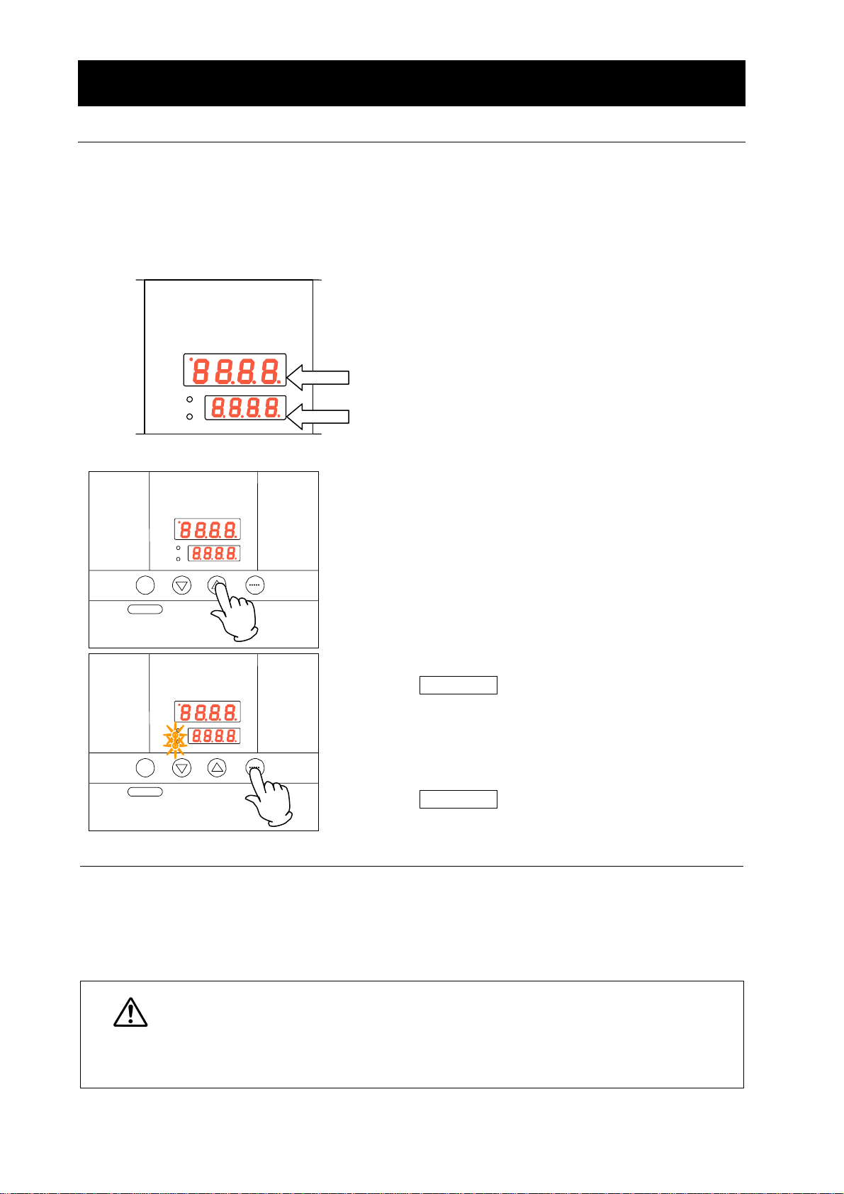
1.Turn the power switch ON. (Turn the power switch to
“ON.”)
When the power switch is turned ON, the intial values will
be displayed for about four seconds, then the initial
screen will appear and the current chamber temperature
and the previous set temperature are displayed on each
of the indicators.
Measured temperature screen: Displays the current
chamber temperature
Set temperature screen: Displays the previous set
temperature
2. Setting the temperature
Set a temperature using the ▼▲ keys.
MEASURED TEMP.
HEATE
RU
TIMER
SUB MENU
SET TEMP.
℃
RUN
STOP
When you want to correct
setting errors or change
settings
① When you want to lower the set temperature during fixed temperature
Caution
operation, note that it takes some time to reach the reset temperature since the
unit has no cooling capacity.
② Immediately after operation has been stopped, the temperature in the chamber
is around the set temperature. Operation stop refers only to machine stop and
time needed for decreasing the emperature in the chamber is not considered.
3. Starting operation
Press the RUN/STOP key longer.
Fixed value operation will start and the RUN lamp and the
HEATER lamp come on.
4. Stopping operation
Press the RUN/STOP key longer.
Operation stops, the RUN lamp goes off and the screen
switches to the initial setting screen.
When you want to change settings, press the ▼▲ keys on
the current screen to enter the setting mode where you can
change settings. Blink stops three seconds after three
seconds after change and setting is completed.
19
Page 22

4. Operating procedures
R
N
y
R
N
RRUN
Operating procedures (quick auto stop operation)
Used when you want to “stop fixed temperature operation being performed automatically in several
hours. Quick auto stop operation is a function to enable auto stop timer setting during operation.
Procedures for quick auto
stop operation
MEASURED TEMP.
℃
②
RUN
STOP
TIMER
SUB MENU
HEATE
RU
①
SET TEMP.
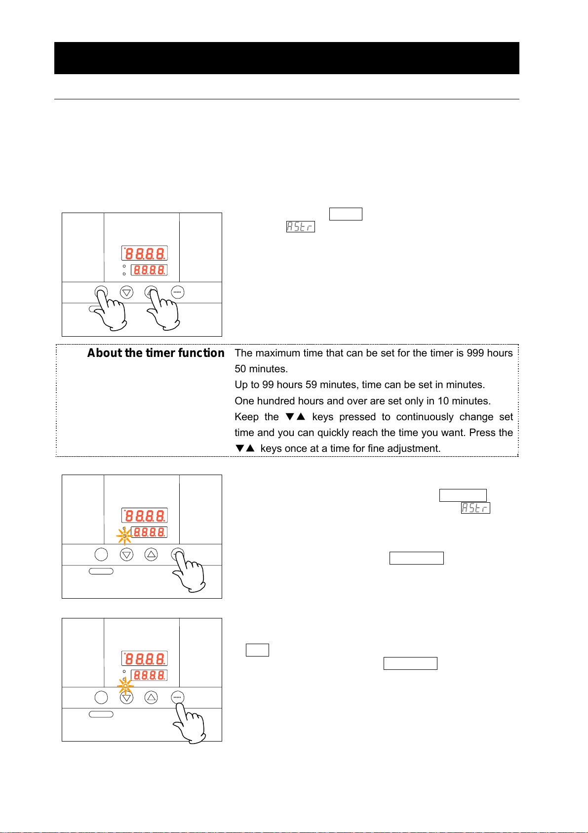
1. Setting time period before stop during fixed
temperature operation
①
Make sure that the RUN lamp is illuminated to
indicate the unit is in operation.
Press the TIMER key.
Characters AStP are indicated on the
measured temperature screen to indicate the auto
stop operation mode and set duration blinks on the
set temperature screen.
② Set a duration you want using the ▼▲ keys.
About the timer function
The maximum time that can be set for the timer is 999 hours
50 minutes.
Up to 99 hours 59 minutes, time can be set in minutes.
One hundred hours and over are set only in 10 minutes.
Keep the
time and
▼▲ keys pressed to continuously change set
ou can quickly reach the time you want. Press the
▼▲ keys once at a time for fine adjustment.
MEASURED TEMP.
℃
TIMER
SUB MENU
HEATE
RU
SET TEMP.
RUN
STOP
2. Starting timer operation
When the time you want is set, press the RUN/STOP key
while the set temperature screen is blinking.
The RUN lamp blinks and timer operation is started.
Timer starts counting when the temperature in the
chamber reaches the set temperature.
Once timer counting is started, the set temperature screen
changes to the remaining time display.
MEASURED TEMP.
℃
RUN
STOP
HEATE
SET TEMP.
TIMER
SUB MENU
3.Stopping and ending timer operation
Operation stops automatically when the set temperature
has elapsed.
Characters End
blink on the set temperature
screen to indicate operation has ended.
Press the RUN/STOP key for approx. one second to end
the timer operation mode. The screen switches to the
initial setting screen.
20
Page 23

When you want to correct
set temperature or set time,
or change settings
4. Operating procedures
Operating procedures (quick auto stop operation)
When you want to change settings, press the ▼▲ keys on
the current screen to enter the setting mode where you can
change settings. Blinking stops three seconds after change
and setting is completed. Note, however, that temperature
changes after timer activation are counted also while
temperature is changing.
When you want to change settings before timer activation,
press the TIMER key on the current screen to enter the
setting mode where you can change settings. Enter a time
duration from when the set temperature is reached to the
time the device shall be stopped.
When you want to change settings after timer activation,
press the TIMER key on the current screen to enter the
setting mode where you can change settings. Note,
however, you need to set a time calculated by adding the
time already passed to the time to be added.
After change has been made, press the RUN/STOP key to
complete the process.
When you want to stop quick auto stop operation in the
middle of it, press the RUN/STOP key long once to stop
device control once, then make settings again in the
appropriate mode.
In terms of the remaining time display
dot indicates count down and an illuminating dot indicates a
wait status (while temperature is increasing or decreasing to
the set temperature) during which the timer has stopped
counting.
21
a blinking
Page 24

4. Operating procedures
R
N
R
N
R
N
Operating procedures (auto stop operation)
This mode automatically stops fixed temperature operation after a certain time from its start set with
the timer.
Procedures for auto stop
operation
MEASURED TEMP.
HEATE
RU
TIMER
SUB MENU
①
SET TEMP.
②
℃
RUN
STOP
About the timer function
MEASURED TEMP.
HEATE
RU
TIMER
SUB MENU
MEASURED TEMP.
HEATE
RU
TIMER
SUB MENU
SET TEMP.
SET TEMP.
℃
RUN
STOP
℃
RUN
STOP
1. Setting a stop time
After confirming the temperature you want is set,
①
Press the TIMER key to display characters
AStP on the measured temperature screen that
indicate auto stop operation.
The set time is displayed on the set temperature
screen.
②
Set a time you want using the ▼▲ keys.
Pressing the ▼▲ keys makes the set time blink.
The time is determined when blinking stops.
The maximum time that can be set for the timer is 999 hours
50 minutes.
Up to 99 hours 59 minutes, time can be set in minutes.
One hundred hours and over are set only in 10 minutes.
Keep the ▼▲ keys pressed to continuously change set
time and you can quickly reach the time you want. Press
▼▲ keys once at a time for fine adjustment.
the
2. Starting timer operation
When the time you want is set, press the RUN/STOP key
for about one second while characters AStP that
indicate auto stop operation are displayed on the
measured temperature screen and the set time on the set
temperature screen.
The RUN lamp blinks and timer operation is started.
Timer starts counting when the temperature in the
chamber reaches the set temperature.
Once timer counting is started, the set temperature screen
changes to the remaining time display.
3. Stopping and ending timer operation
Operation stops automatically when the set temperature
has elapsed.
Characters End
blink on the set temperature
screen to indicate operation has ended.
Press the RUN/STOP key for approx. one second to end
the timer operation mode. The screen switches to the
initial setting screen.
22
Page 25

When you want to correct
set temperature or set time,
or change settings
4. Operating procedures
Operating procedures (auto stop operation)
When you want to change settings, press the ▼▲ keys on
the current screen to enter the setting mode where you can
change settings. Blinking stops three seconds after change
and setting is completed. Note, however, that temperature
changes after timer activation are counted also while
temperature is changing.
When you want to change settings before timer activation,
press the TIMER key on the current screen to enter the
setting mode where you can change settings. Enter a time
duration from when the set temperature is reached to the
time the device shall be stopped.
When you want to change settings after timer activation,
press the TIMER key on the current screen to enter the
setting mode where you can change settings. Note,
however, you need to set a time calculated by adding the
time already passed to the time to be added.
After change has been made, press the RUN/STOP key to
complete the process.
Auto stop operation is not available together with auto start
operation.
When you want to stop auto stop operation in the middle of
it, press the RUN/STOP key long once to stop device
control once, then make settings again in the appropriate
mode.
In terms of the remaining time display
dot indicates count down and an illuminating dot indicates a
wait status (while temperature is increasing or decreasing to
the set temperature) during which the timer has stopped
counting.
23
a blinking
Page 26
4. Operating procedures
RRUN
y
y
R
N
R
N
Operating procedures (auto start operation)
This mode automatically starts fixed value operation after a certain time from its start set with the
timer.
However, operation does not stop automatically but needs to be stopped manually.
Procedures for auto start
operation
MEASURED TEMP.
HEATE
SET TEMP.
TIMER
SUB MENU
①
℃
②
RUN
STOP
1. Setting an operation start time
After confirming the temperature you want is set,
①
Press the TIMER key to display characters
AStr on the measured temperature screen that
indicate auto start operation.
The set time is displayed blinking on the set
temperature screen.
② Set a time you want using the ▼▲ keys.
Pressing the
▼▲ ke
s makes the set time blink.
The time is determined when blinking stops.
About the timer function
MEASURED TEMP.
HEATE
RU
SET TEMP.
TIMER
SUB MENU
MEASURED TEMP.
HEATE
RU
SET TEMP.
TIMER
SUB MENU
The maximum time that can be set for the timer is 999 hours
50 minutes.
Up to 99 hours 59 minutes, time can be set in minutes.
One hundred hours and over are set only in 10 minutes.
Keep the
time and
▼▲ keys pressed to continuously change set
ou can quickly reach the time you want. Press the
▼▲ keys once at a time for fine adjustment.
2. Starting timer operation
When the time you want is set, press the RUN/STOP key
℃
for about one second while characters AStr that
indicate auto start operation are displayed on the
measured temperature screen and the set time on the set
RUN
STOP
temperature screen.
Timer starts counting when the RUN/STOP key is pressed
and RUN lamp blinks.
Display on the measured temperature screen switches
from set time display to remaining time display.
3.Stopping and ending timer operation
Operation automatically starts at the set time and the
RUN lamp comes on.
℃
To stop operation, press the RUN/STOP key for approx.
one second to end the timer operation mode. The screen
RUN
STOP
switches to the initial setting screen.
24
Page 27

When you want to
correct set temperature or set time, or
change settings
4. Operating procedures
Operating procedures (auto start operation)
When you want to change the set temperature during timer counting,
press the
screen to the set temperature input mode, which blinks to enable
change of the set temperature with the ▼▲ keys.
When you want to change the set time during timer counting, press
the TIMER key during that status to switch the set temperature
screen to the set time input mode, which blinks to enable change of
the set time with the ▼▲ keys.
In either case, the set temperature screen will stop blinking after a
while and switche to the timer count mode and the change made is
determined. Note, however, when you change the set time you need
to set a time calculated by adding the time already passed to the
time to be added.
When operation has started after the auto start time, you cannot
change the set time.
When you want to stop auto start operation in the middle of it, press
the RUN/STOP key long to stop device control once, then make
settings again in the appropriate mode.
▼▲ keys during that status to switch the set temperature
In terms of the remaining time display
indicates count down and an illuminating dot indicates a wait status
(while temperature is increasing or decreasing to the set
temperature) during which the timer has stopped counting.
a blinking dot
25
Page 28

4. Operating procedures
R
N
Useful functions (calibration offset function)
Using the calibration offset
function
Calibration offset function compensates any differences
between the target temperature in the chamber and the
control temperature of the controller (sensor temperature.)
The function can compensate in parallel to either plus or
minus side for the whole temperature band of the unit.
The lock can be set or released with the SUB MENU keys.
The temperature is set at “0” on shipping from the
factory.
Control
temperature after
minus side
compensation
Current
temperature
Control
temperature after
plus side
compensation
① Start operation at the target set temperature and confirm
the temperature in the chamber with a temperature
③
MEASURED TEMP.
HEATE
TIMER
SUB MENU
℃
RU
SET TEMP.
RUN
STOP
④
recorder after temperature has stabilized.
② Confirm the difference between the set temperature and
that in the chamber.
③ Press the TIMER key (SUB MENU key) long to enter the
sub menu mode.
Press the TIMER key (SUB MENU key) several times to
select the characters cAL that indicates the
calibration offset function.
④ Enter the difference between the set temperature and
the temperature in the chamber using the
▼▲ keys
and press the TIMER key (SUB MENU key) long to exit
the sub menu mode. (When you want to set the key
lock function, proceed to character selection process for
the key lock function without pressing the TIMER key
(SUB MENU key) long.)
26
Page 29

* You can set either of + or – side for the offset compensation temperature.
When compensation is set for the – side, the measured temperature display decreases by the
compensation temperature while the temperature in the chamber increases by the same
amount.
When compensation is set for the + side, the measured temperature display increases by the
compensation temperature while the temperature in the chamber decreases by the same
amount.
* Since too large a compensation value may result in larger difference between the actual and
indicated temperatures and may present a danger, consult our nearest sales office before
entering a large compensation value.
* The device has, in addition to the calibration offset function, the two-point compensation function
that adjusts offset for the lower temperature range and higher temperature range, for which
adjustment temperatures have been input on shipping from the factory.
* Consult the nearest sales office before attempting validation work for the temperature adjusting
device.
27
Page 30

R
N
R
N
R
N
Using the lock function
MEASURED TEMP.
HEATE
RU
SET TEMP.
TIMER
SUB MENU
MEASURED TEMP.
HEATE
RU
SET TEMP.
TIMER
SUB MENU
℃
RUN
STOP
℃
RUN
STOP
4. Operating procedures
Useful function (setting lock function)
This function locks the set operation status.
The temperature is set at “off” on shipping from the
factory.
① Press the TIMER key (SUB MENU key) long to enter
the sub menu mode.
Press the TIMER key (SUB MENU key) several
times to select the characters Lock that
indicate the setting lock function.
③ “Off” is displayed on the set temperature screen. To
lock settings, change to “on” using the
Press the TIMER key (SUB MENU key) long to exit
the sub menu mode.
▲ key.
MEASURED TEMP.
HEATE
RU
TIMER
SUB MENU
SET TEMP.
℃
RUN
STOP
(3) To release lock, press the TIMER key (SUB MENU
key) long again and select the characters Lock
that indicate setting lock using the ▼▲ keys.
Lock is released when “off” is selected using the
key.
▼
* When the lock function is “on”, keys other than the
RUN/STOP key and the TIMER key (SUB MENU
key) are locked.
28
Page 31

R
N
RRUN
Using the power outage
compensation function
MEASURED TEMP.
℃
RUN
STOP
HEATE
RU
SET TEMP.
TIMER
SUB MENU
4. Operating procedures
Useful function (power outage compensation function)
The power outage compensation function returns the main
unit operation to the resume status after recovery from
power outage, or keeps the current stop status.
The function is set at “on” on shipping from the factory.
① Press the TIMER key (SUB MENU key) long to enter
the sub menu mode.
Press the TIMER key (SUB MENU key) several
times to select the characters Pon that
indicate the power outage compensation function.
MEASURED TEMP.
℃
RUN
STOP
HEATE
SET TEMP.
TIMER
SUB MENU
② “On” is displayed on the set temperature screen. The
device keeps stop status after recovery from power
outage when this setting is set to “off” using the
▼
key.
Press the TIMER key (SUB MENU key) long to exit
the sub menu mode.
29
Page 32

5. Cautions on handling
1. About handling of flammable or combustible solution
The unit is not explosion proof. Take special care for handling samples on which explosive
substances, combustible substances or substances containing them. Flammable or
combustible solution will evaporate when left at a room temperature (or at a lower
temperature for some types of solutions) and may be ignited and explode from switches,
lights and other ignitable sources. Be sure to assure sufficient ventilation when using
these materials.
See section “13. List of dangerous materials” on page 41.
2. Ban on use/countermeasures when an error occurs
If smoke emerges from the unit or an odd odor is felt, immediately turn the power switch on
the main unit off, turn the power supply off and contact your dealer or a Yamato sales office
for inspection. Otherwise, a fire or an electrical shock may result. The user shall never
attempt to repair the unit to avoid any possible dangers.
3. Secure sufficient ventilation for the unit.
Do not operate the unit when its vent holes on the side and rear panels covered or blocked.
Internal temperature of the unit will rise degrading the performance and an accident, a
malfunction or a fire may result.
4. Do not allow liquid to spill over the unit.
Do not allow liquid to spill over the unit. Pay special attention not to allow liquid to enter
into the vent holes on the side and rear panels of the unit. If liquid is spilt over or into the
unit, do not try to operate it any further. Other wise, an accident, a malfunction, a fire or an
electrical shock may result.
5. Do not allow a metal piece to fall into the unit.
Do not allow a clip, a staple, a screw or other metal pieces to fall into the unit.
Stop operating the unit if a metal piece has dropped into the unit.
Other wise, an accident, a malfunction, a fire or an electrical shock may result.
6. Do not open the cabinet.
Do not open panels or covers fixed on the unit, or do not operate the unit with any of those
open. Other wise, an accident, a malfunction, or an electrical shock may result.
7. Always operate the unit at a correct ambient temperature.
The operating temperature range is room temperature range from +5
temperature. Never try to operate the unit outside the operating temperature range.
8. Do not attempt to modify the unit.
The user shall never try to modify the unit; other wise, an accident, a malfunction, a fire or
an electrical shock may result.
Warning
~80℃ above room
30
Page 33

5. Cautions on handling
Caution
1. Do not step on the unit.
Do not step on the unit. Otherwise, the unit may trip over or be damaged resulting in a
personal injury or a malfunction.
2. Do not put or drop an object on the unit.
Do not put or drop an object on the unit. Since the unit contains high precision devices,
vibrations or shock may cause a malfunction.
3. When a thunder is heard.
When a thunder is heard, turn the power switch on the main unit off then turn the main
power off immediately. Otherwise, a lightning strike may result and cause a fire.
4. During night and not to be operated for a long period of time.
During the night and when you want to stop the unit for a longer period of time, turn the
power switch to “off” and pull out the power cord from the power supply.
5. About recovery from power outage.
When the power is applied again after the unit has stopped due to power outage, the unit
will automatically return to the status immediately before the power outage and resumes
operation.
Turn the power switch off if you do not want to resume operation by automatic recovery.
6. About two-tier stacking
Use the dedicated optional parts to stack units in two tiers. Contact you dealer or the
nearest sales office for the dedicated optional part.
7. When opening or closing the door
When opening or closing the door, do not put your hand or face close to the area the door
moves (space).
The door may touch your hand or face and causing an injury.
8. Do not operate the unit with the door open.
When the unit is operated with the door open, proper temperature control is not possible
and the heater may overheat causing a possible danger. Be sure to operate the unit with
the door closed.
9. About installation of shelf boards and samples
Place shelf boards and samples according to “Installation procedures
page 7. Otherwise, the optimal performance of the unit will not be obtained and an
accident or a malfunction may result.
10. Do not attempt to do anything other than specified in this operation manual.
Do not attempt to do anything other than specified in this operation manual. Otherwise, an
unexpected accident may result.
・precautions“ on
31
Page 34

6. Maintenance procedures
Daily inspection/maintenance
Be sure to perform daily inspection and maintenance to assure reliable operation of the unit.
Warning
● Be sure to pull out the power cord unless necessary before trying to do inspection and
maintenance works.
● Start these works after the device has returned to the normal temperature.
● Never try to disassemble the unit.
Caution
● Wipe off any dirt with a tightly wrung soft cloth. Never try to clean the unit with benzene,
thinner or scouring powder, or rub with a scrubbing brush. Deformation, degradation or
discoloration may result.
Maintenance of the internal chamber
Stop operation and turn the power switch to OFF. Pull out the power cord off the distribution
board and the wall outlet. Confirm the temperature in the device and remove shelf boards and
clamps.
The internal chamber, shelf boards and shelf clamps are made of stainless steel and reinforced
glass is used for the inner door. To clean these items, thoroughly wipe with a cloth moistened
with cleaning alcohol then wipe gently with a dry cloth.
Never use acid detergent, alkaline detergent, oil or organic solvent, which may cause corrosion or
damage to the products.
There are sharp protrusions inside the internal chamber, shelf boards and
shelf pillars and shall be handled with special care to avoid personal injury.
Be sure to wear gloves since handling with bare hands may present danger.
32
Page 35
7. When the unit is not to be used for a long time
or when disposing
When the unit is not to be used for a long time or when disposing
Caution
When the unit is not going to be used for a long
time
● Turn the power switch to off and pull out the
power cord.
When disposing the unit
● Do not leave the unit in the area where
● Be sure to remove handles before disposing
● In general, dispose the unit as a bulky
Warning
children may have access.
the unit to prevent the doors from locking.
waste.
Notes about disposition
Always pay attention to the preservation of the global environment.
・
We highly recommend taking the unit apart as far as possible for separation or recycling to
contribute to the preservation of the global environment. Major components and materials for
the unit are as follows:
Names of major
components
Major exterior components
Major materials
Exterior Steel plate SPCC (powder coating)
Internal chamber Stainless steel
Packing, gaskets, etc. Neoprene rubber
Major electric parts
Switches and relays Resin, cupper
Boards Glass fiber
Heater Iron-chrome
Power cord Synthesized rubber sheath, cupper, nickel
33
Page 36

8. Troubleshooting
Safety device and error codes
The unit has the self diagnostic function with a controller and a separate safety device.
Table below shows possible causes and measures when the safety device is triggered.
[Error codes]
When a functional or mechanical abnormality occurs, the alarm lamp on the control panel
comes on, an error code will be displayed and the alarm buzzer sounds. When an
abnormality occurs, confirm the error code and immediately stop operation.
Safety device Symptom Possible causes and measures
Sensor error
Memory error
Measured
temperature error
appears
appears
----
---- appears
z Error in the temperature input circuit
z Disconnection or other errors in the
temperature sensor.
z Measured temperature is outside the
displayable range
Contact our service department.
z Memory setting error
Contact our service department.
z When the upper limit alarm of the temperature
alarm function is triggered.
Contact our service department.
34
Page 37

If any of the symptoms below occurs
Symptom Check
8.Troubleshooting
When a malfunction is suspected
Turning the MCB to on will
not activate the unit.
Temperature does not rise.
Temperature fluctuates
during operation.
Displayed temperature
differs from the
measurement.
If power outage occurs
When the power is applied again after the unit has stopped due to power outage, the unit will
automatically return to the status immediately before the power outage and resumes operation.
Turn the SW off if you do not want to resume operation by automatic recovery.
¡If the symptom does not match any of the above, immediately turn the power switch on the
main unit off, pull out the power cord from the power supply and contact your dealer or one of
our sales offices.
● If the power cord is connected to the power supply securely.
● If power outage is not occurring.
● If the standalone overheat prevention device is working.
● If the set temperature is below that in the device.
● If the power supply voltage has declined.
● If the ambient temperature is not low.
● If cooling load for inside the chamber is not too large.
● If the set temperature is appropriate.
● If the power supply voltage has declined.
● If ambient temperature fluctuates widely.
● If cooling load for inside the chamber is not too large.
● If the calibration offset setting is not other than “0”. Set it to
“0.”
Confirm settings in “Useful functions (calibration offset
function)
” in page 26.
35
Page 38

9. After sales service and warranty
When requesting a repair
When requesting a repair
If any trouble occurs, immediately stop operation, turn the power switch off, pull out the power
plug and contact your dealer or our sales office.
Information necessary for requesting a repair
●
Model name of the product
●
Serial number
Date (y/m/d) of purchase
●
●
Description of trouble (as in detail as possible)
Be sure to indicate the warranty card to our service representative.
See the warranty card or the nameplate installed on the unit.
See 3. Names and functions of parts on page 11.
Warranty card (attached separately)
●Warranty card is given by your dealer or one of our sales offices and please fill in your dealer,
date of purchase and other information and store securely.
●Warranty period is one full year from the date of purchase. Repair service for free is available
according to the conditions written on the warranty card.
●For repairs after the warranty period consult your dealer or one of our sales offices. Paid
repair service is available on your request when the product’s functionality can be maintained
by repair.
Minimum holding period of repair parts
The minimum holding period of repair parts for this product is seven years after end of
production.
Repair parts here refer to parts necessary for maintaining performance of the product.
36
Page 39

10. Specifications
Model
IC103C/103CW
IC113C/113CW
IC403C/403CW
IC413C/413CW
IC603C
IC613C
IC803C
IC813C
Operating
temperature range
Temperature control
precision
Temperature
Performance
distribution precision
0.2 kW
Heater
ism
Mechan
Controller Model CN40B-Y PID control
Control system PID control with a micro computer
Setting system Digital setting using up/down keys
Operation mode
Control part
Sensor K-thermocouple
Auxiliary functions
Controller
Self diagnostic
function
SUS pipe
heater
Fixed temperature operation, quick auto stop operation
Lock function, power outage compensation function, calibration offset
Temperature sensor error, memory error, auto overheat prevention,
Room temperature +5℃~80℃
(no load at an ambient temperature of 23℃)
±0.5℃ (setting: 37℃)
±1℃ (setting: 37℃)
0.3 kW 0.4 kW 0.73 kW
Iron-chrome wire heater
Auto stop operation, auto start operation
function
measured temperature error
Protection device An over current fuse
Safety device
Outer dimensions
(mm) (w x d x h)
Internal dimensions
(㎜) (w x d x h)
Internal volume
Inner door None Reinforced glass door x 1
Standard
Weight
(tentative value)
Power supply
Included items
*Performance values are for the VAC115 power supply.
*Operating environmental temperature range for this device is 5℃~35℃.
430×397×606 560×606×820 710×656×870
350×300×360 450×480×450 600×530×500
37ℓ 97ℓ
Approx. 17 kg Approx. 45 kg Approx. 65 kg Approx. 102 kg
VAC115
50/60Hz 1.8A
VAC220
50/60Hz 1A
Shelf withstand load Approx. 15kg/each board
VAC115
50/60Hz 2.8A
VAC220
50/60Hz 1.4A
Shelf board x 2 Shelf board x 4
Operating instructions, warranty card
VAC115
50/60Hz 3.7A
VAC220
50/60Hz 1.8A
710×656×
1619
600×530×
1000
159ℓ 318ℓ
Reinforced
glass door x 2
VAC115
50/60Hz 6.6A
VAC220
50/60Hz 3.3A
37
Page 40

IC103C/103CW/403C/403CW/603C/803C
11. Wiring diagram
AC115V
SW
F
H2
H1
T
1
1
2
2
1
3
4
4
2
1
SSR
TH
3
4
1
+
2
3
-
4
5
TB1
6
6
7
7
8
9
1 1
CN1
22
CONT
Symbol Part name Symbol Part name
SW power switch SSR No-contact relay
F Fuse CONT Control circuit board
T Terminal block PIO Display circuit board
H1, H2 Heater TH Control sensor
CN1
22
PIO
38
Page 41

IC113C/113CW/413C/413CW/613C/813C
11. Wiring diagram
AC220V
SW
F
H1
H2
T
1
1
2
2
1
3
4
4
2
1
SSR
TH
3
4
1
+
2
CN1
3
-
4
5
TB1
6
6
7
7
8
9
22
CONT
Symbol Part name Symbol Part name
SW power switch SSR No-contact relay
F Fuse CONT Control circuit board
T Terminal block PIO Display circuit board
H1, H2 Heater TH Control sensor
11
CN1
22
PIO
39
Page 42

12. List of replacement parts
Replacement parts
Symbol Part name Standard Maker Code No.
SW power switch
F Fuse
250VAC 16A
250VAC 5A
(IC103C/113C/103CW/113CW)
250VAC 10A
(IC403C/403CW/413C/413CW/6
YSJ SJA07732
YSJ SJA07733
YSJ SJA07734
03C/613C/803C/813C)
TH Control sensor
CONT Planar board CN40B-Y
PIO Display circuit board CN40B-Y
SSR No-contact relay NTD2425 YSJ SJA04630
Power cord kit 1.25sq 3P plug YSC 2130010005
H1・2
Heater
φ3.2*55*2000
115V 100W
(IC103C/113C/103CW/113CW)
115V 150W
(IC403C/403CW/413C/413CW)
115V 200W
(IC603C/613C)
YSJ SJA14012
YSC
YSC
YSJ
YSC
YSC
LT00007640
LT00007639
SJA04477
LT00020606
LT00020607
115V 365W
(IC803C/813C)
YSC
LT00020608
40
Page 43

13. List of dangerous materials
Never use an explosive substance a flammable substance or a substance containing them
for this device.
① Nitroglycol, glycerine trinitrate, cellulose nitrate and other explosive nitrate esters
② Trinitrobenzen, trinitrotoluene, picric acid and other explosive nitro compounds
Explosive
Flammable substances
substance
③ Acetyl hydroperoxide, methyl ethyl ketone peroxide, benzoyl peroxide and other organic
Explosive
substance
peroxides
Metal “lithium”, metal “potassium”, metal “natrium”, yellow phosphorus, phosphorus sulfide,
red phosphorus, celluloids, calcium carbide (a.k.a, carbide), lime phosphide, magnesium
powder, aluminum powder, metal powder other than magnesium and aluminum powder,
sodium dithionous acid (a.k.a., hydrosulphite)
Explosive
substances
① Potassium chlorate, sodium chlorate, ammonium chlorate, and other chlorates
② Potassium perchlorate, sodium perchlorate, ammonium perchlorate, and other
perchlorates
③ Potassium peroxide, sodium peroxide, barium peroxide, and other inorganic peroxides
④ Potassium nitrate, sodium nitrate, ammonium nitrate, and other nitrates
⑤ Sodium chlorite and other chlorites
Oxidizing substances
⑥ Calcium hypochlorite and other hypochlorites
① Ethyl ether, gasoline, acetaldehyde, propylene chloride, carbon disulfide, and other
substances with ignition point at a degree 30 or more degrees below zero.
② n-hexane, ethylene oxide, acetone, benzene, methyl ethyl ketone and other substances
with ignition point between 30 degrees below zero and less than zero.
③ Methanol, ethanol, xylene, pentyl acetate, (a.k.a.amyl acetate) and other substances with
ignition point between zero and less than 30 degrees.
④ Kerosene, light oil, terebinth oil, isopenthyl alcohol(a.k.a. isoamyl alcohol), acetic acid
Flammable substances
and other substances with ignition point between 30 degrees and less than 65 degrees.
Hydrogen, acetylene, ethylene, methane, ethane, propane, butane and other gases
gas
combustible at 15 degrees at one air pressure.
Combustible
41
Page 44

14. Standard installation manual
*Install the product according to the following: (Confirm separately for optional items or special
specifications)
Model Serial number Date
№ Item Implementation method
1 Included items
2 Installation
Operation-related matters
1 Source voltage
2 Operation start
Description
Operational
1
descriptions
2 Error codes
Maintenance
3
and inspection
Completion of
4
installation
Entries
Installation mgr.
(company name)
TOC No. Reference page of the
operating instruction manual
Specifications
Check for number of staffs against
the included item field
・ Visual check of environmental
conditions
Caution: Take care for
environment
・Securing a space
・ Measure the user side voltage
(outlet) with a tester
・ Measure voltage during operation
(shall meet the standard)
Caution: Always use a plug that
meets the specification for
attaching to the power
switch.
・Starts operation
Performs fixed temperature ope-
ration, auto stop operation or auto
start operation
Explain operations of each component according to the operational
instructions
Explain the customer about error
codes and procedures for release
according to the operational
instructions
Explain operations of each component according to the operational
instructions
・ Fill in the installation date and the
installation mgr. on the nameplate
of the main unit
・ Fill in necessary information to
the warranty card and hand it
over to the customer
・ Explanation of the route for
after-sales service
10.Specifications field P.37
2. Before operating the
unit
・On the installation site
2. Before operating the
unit
・ Be sure to connect
the ground wire.
・Power supply is ….
10. Specifications
・ Specification-power
supply
2. Before operating the
unit
・Installation
procedures…
4. Operating procedures
4. Operating procedures
・Operating
procedures
1. Safety precautions
~13. List of dangerous
materials
8. Troubleshooting
~9. After sales service
and warranty
6. Maintenance
procedures
・ Daily
inspection/maintena
nce
9. After sales service and
warranty
Installation mgr.
P. 4
P. 6
P. 6
P.37
P. 4 ~
P. 1 6 ~
29
P.16
~29
P. 1
~41
P.34
P.32
P.36
36
Judg
ment
Judg
ment
9
42
Page 45

Limited liability
Be sure to use the unit strictly following the handling and operating instructions in this
operating instruction.
Yamato Scientific Chongqing Co., Ltd. assumes no responsibility for an accident or a
malfunction caused by use of this product in any way not specified in this operating
instruction.
Never attempt to perform matters prohibited in this operation instruction.
Otherwise, an unexpected accident may result.
Notice
● Descriptions in this operating instruction are subject to change without notice.
● We will replace a manual with a missing page or paging disorder.
Operating instruction
General purpose incubator
IC103C/103CW/403C/403CW/603C/803C, IC113C/113CW/413C/413CW/613C/813C
Fifth edition 10 December 2010
Yamato Scientific America, Inc.
925 Walsh Ave, Santa Clara, CA 95050
Tel:408-235-7725
For technical information
and service,call: 1-800-292-6286
http://www.yamato-usa.com
43
 Loading...