

Page 1

● Thank you for purchasing “Constant Temperature
Precision Oven DF832/1032 and DH832/1032” of
Yamato Scientific Co., Ltd.
● This product has not been designed for medical
applications. Use this as a laboratory drying
sterilizer only.
● In order to use this Equipment properly, please read
this Instruction Manual and Warranty Card
thoroughly before use. Keep them in safe place
close to this Equipment so that you can refer to
them any time.
Warning: Please read the important warning
notes in this Manual carefully and
thoroughly, and get the good
understanding of their contents
before using this Equipment.
Constant Temperature Precision Oven
(Fine Oven)
DF832/1032
DH832/1032
Instruction Manual
First Edition
Yamato Scientific Co., Ltd.
Printed on recycled paper
Page 2

Contents
1. Safety Precautions ................................................................ 1
Explanation of symbols .................................................................1
List of symbols .........................................................................2
Warning and Cautions ..................................................................3
2. Before operating the Equipment .................................................... 4
Precautions when installing the Equipment ................................................4
3. Names and functions of each part .................................................. 7
Main unit ..............................................................................7
Control Panel ..........................................................................8
4. Operating procedure .............................................................. 9
Prior confirmation ......................................................................9
Date & Time setting ...................................................................10
Buzzer function selection ...............................................................11
Fixed temperature operation ............................................................13
Auto stop operation....................................................................17
Auto start operation ...................................................................20
Using and setting of the variable wind speed function ......................................23
Program operation ....................................................................25
How to copy or delete programs .........................................................35
About the wait function .................................................................37
Setting key lock mode .................................................................38
Calibration offset ......................................................................39
Setting the recovery mode ..............................................................40
Resetting integrated CO2 volume and CO2 emission factor .................................41
Backup data saving / reading out / resetting...............................................43
Monitoring data .......................................................................44
Independent Overheat Prevention Device ................................................46
5. Handling precautions ............................................................ 47
Warning ............................................................................47
Caution .............................................................................48
6. Maintenance method ............................................................. 53
Daily inspection/maintenance ...........................................................53
7. Long storage and scrap .......................................................... 54
When not using the Equipment for a long time / when scrapping ...................................54
Matters to consider when scrapping the Equipment ........................................54
8. When a trouble occurs ........................................................... 55
Message error table ...................................................................55
Troubleshooting ......................................................................57
9. After sales service and warranty .................................................. 58
Request to repair parts .................................................................58
10. Specifications .................................................................. 59
Page 3

Specifications ........................................................................59
12. Wiring diagram ................................................................. 61
DF/DH832 Wiring diagram ............................................................61
DF/DH1032 wiring diagram ..........................................................62
Wiring diagram part symbols ............................................................63
13. List of dangerous substances .................................................... 64
Page 4

1
About symbols
Various symbols are provided in this Instruction Manual and on the
product to ensure safe operation. Improper handling of this Equipment
without understanding their contents will lead to the results classified
below. Be sure to fully understand the description of symbols below
before proceeding to the text of this Manual.
Warning
Caution
Indicates a situation which may result in minor injury (Note 2)
and property damages (Note 3.)
( Note 1) Serious injury means a wound, an electrical shock, a bone fracture or
intoxication that may leave after effects or require hospitalization or
outpatient visits for a long time
( Note 2) Minor injury means a wound or an electrical shock that does not require
hospitalization or outpatient visits for a long time.
( Note 3) Property damage means damage to facilities, devices and buildings or other
properties.
Meanings of symbols
This symbol indicates a matter urging user to follow the warning
(“caution” included).
Specific description of warning is indicated near this symbol.
This symbol indicates prohibitions.
Specific prohibition is indicated near this symbol.
This symbol indicates matters that the user must perform.
Specific instruction is indicated near this symbol.
Indicates a situation which may result in death
or serious injury (Note 1.)
1. Safety Precautions
Explanation of symbols
Page 5

General
Warnings
Danger!: High
Voltage
Danger!: High
Temperature
Danger!: Moving
Part
Danger!:
Explosion Hazard
General Cautions
Caution:
Electrical Shock!
Caution: Burns!
Caution: Heating
Container without
water!
Caution: Water
Leak!
Caution: For
water only
Caution: Toxic
Chemicals
General
Prohibited
Actions
No open flame
Do not
disassemble
Do not touch
General
Mandatory
Actions
Connect
grounding wire
Leveled
Installation
Disconnect Power
Regular
Inspection
Warning
Caution
1. Safety Precautions
List of symbols
Prohibitions
Compulsions
2
Page 6

Warning
Never operate the Equipment in an atmosphere where flammable or explosive gas is
present.
Never operate this Equipment in an atmosphere where flammable or explosive gas is
present.
This Equipment is not explosion-proof. It will cause fire/explosion. (Refer to “Chapter 13. List
of Dangerous Substances” on P.64).
Ground always the Equipment.
Ground always this Equipment properly in order to avoid electric shock due to electrical
leakage.
Turn the power of the controller and the ELB off immediately when you notice any
abnormality.
Turn the power of the controller and the ELB off immediately and unplug Power Cord from
outlet or disconnect the breaker of switch board of facilities, If smoke or strange smell is
generated from this Equipment by chance. It may cause fire or electrical shock.
Do not operate at Power Cord/Power Cable bundled state.
Do not operate at Power Cord/Power Cable bundled state. If it is operated in such a manner,
it will overheat, and then cause fire.
Do not damage Power Cord/Power Cable.
Do not damage Power Cord/Power Cable by bending, pulling, or twisting with force. It may
cause fire or electric shock.
Never use an explosive or a combustible substance.
Never use an explosive or a combustible substance or any substances that contain such a
substance. Otherwise an explosion or a fire may result.
Never disassemble nor modify the Equipment.
Never disassemble nor modify this Equipment. Those actions may cause malfunction, fire
or electric shock.
Never touch high temperature sections.
Never touch high temperature sections. Some sections of this Equipment are heated during
and right after operation. Watch out for getting burned.
Caution
Turn immediately the power of the controller and the ELB off at thundering.
Turn immediately the power of the controller and the ELB off at thundering. If not, it may
cause fire or electric shock.
1. Safety Precautions
Warning and Cautions
3
Page 7

Do not install this Equipment in the place where:
・the location is rough, dirty or un-leveled.
・flammable gas, explosive gas or corrosive gas will be generated.
・ambient temperature will be more than 35℃ or less than 5℃.
・ambient temperature will fluctuate. ・Liquid may splash
・there is excessive humidity and dusty. ・there is direct sunlight.
・there is constant vibration. ・outside the building.
・power supply is instable.
Install the Equipment(s) at the place with sufficient space as specified as below.
There is an exhaust port on the back of the unit. When an exhaust duct is not installed on the
premises, take care to assure sufficient space on the rear side and for flammable substances.
When you are going to operate the unit with ventilation (with the damper open), take
appropriate measures to assure sufficient ventilation around the installation site. Insufficient
ventilation around the unit may cause rise in the temperature of the room from hot air from the
exhaust port or allow smoke or gas from specimen to fill the room. Be sure to connect an
exhaust duct to the exhaust port so that hot air will be discharged outside.
Install this Equipment on leveled floor. If it is installed on rough and/or slope floor, vibration or
noise will be occurred, and unexpected trouble and malfunction may be happened.
Weight of this Equipment is as follows:
DF/DH832:approx. 320㎏ DF/DH1032:approx.420kg ( Do not include a shelf board)
Handle this Equipment carefully by Four people at least at the transportation and the installation
1m 以上
60㎝以上 60㎝以上
1m 以上
Min 60cm
Min 60cm
Min1m
Min1m
2. Before operating the Equipment
1. Choose proper place for installation
Precautions when installing the Equipment
2. When operating with ventilation
3. Install the Equipment on leveled location.
4
Page 8

May be injured by moved and/or fallen this Equipment down by earthquake and/or unexpected
impact. Recommend to install this Equipment at the place away from the access door and to take
other safety steps.
May be injured by moved and/or fallen this Equipment down by earthquake and/or unexpected
impact.
Implement appropriate measures against falling down for safety.
Do not operate the Equipment blocked in the radiating slit holes-Louver on its side and back
panels and top panel. Refer to 3. “Name and Functions of each part” on page 8 for the location
of Louvers.
Internal temperature will rise, causing a malfunction of the controller to compromise the
performance as well as to cause a possible accident or a fire.
Do not operate this Equipment at the location of liquid splashing. If Controller of this Equipment
will be wetted by splashing any kind of liquid, it may cause accident, controller malfunction,
electrical shock and/or fire.
Never operate this Equipment in an atmosphere where flammable or explosive gas is present.
This Equipment is not explosion-proof. Spark may be discharged by switching Earth Leakage
Breaker (ELB) “ON(|)” and “OFF(○)” and also relay during operation, and then it may cause
fire or explosion. See Chapter 13. “List of Dangerous Substances” for flammable and explosive
gases on page .64
Connect Power Cord/Power Cable to suitable receptacle/switch board of facilities according to
electrical requirements as follows.
Electrical
requirements:
DF832 AC220V 3 phase 50/60Hz 13.5A or more (ELB capacity;20A)
DF1032 AC220V 3 phase 50/60Hz 17A or more(ELB capacity;30A)
DH832 AC220V 3 phase 50/60Hz 20A or more(ELB capacity;30A)
DH1032 AC220V 3 phase 50/60Hz 28Av(ELB capacity;40A)
The operational voltage range is ±10%, the voltage range where the specified performance is
guaranteed is rating±5%, the frequency is rating±1%.
※ Check line voltage of its receptacle/switch board of facilities and/or whether utilize the same
line with other equipments or not, if this Equipment does not start up/operate even to turn
Earth Leakage Breaker(ELB) On(|). Take correct action for the solution, such as changing
its power source away from other equipment.
These models are designed to operate at 3-phase AC200V. Ask your dealer or an electrical
technician for connection work of the power cord.
Connection requires professional knowledge and skills. A fire or an electrical shock may result if
an unqualified person performs this work.
Wire Color
Facility Supply
Red
Phase R
White
Phase S
Black
Phase T
Green
Ground
G
2. Before operating the Equipment
Precautions when installing the Equipment
4. Implement safety measures when installing the unit.
5. Implement appropriate safety measures after installation.
6. Ventilate sufficiently for the Equipment
7. Do not operate at the location of liquid splashing.
8. Never operate in an atmosphere where flammable or explosive gas is present.
9. Connect Power Cord/Power Cable to receptacle or switch board of facilities.
10. Take care when connecting the power cord.
5
Page 9

・ Require to ground by Electrical Equipment Technical Standards Section 19-calss
D(Grounding Resistance Max. 100Ω) in Japan, if grounding terminal is not provided. Please
contact with local dealer, local electrician, or Yamato Customer Service Center.
・ Connect the terminals firmly to switch board of facilities or appropriate power plug.
・ Power plug itself will not be included as an accessory of this Equipment. Connect to the
power supply facilities that meet the electric capacity.
Wire Color
Facility Supply
Red
Phase R
White
Phase S
Black
Phase T
Green
Ground
Never connect grounding wire to gas line pipe, water line pipe or telephone grounding wire due
to fire or electric shock.
Never operate this Equipment at bundled Power Cord/Power Cable. May heat its Cord/Cable and
then cause fire, if operate at bundled it.
Do not modify, bend forcibly, twist or pull Power Cord/Power Cable. Otherwise, may cause fire
and/or electrical shock.
Do not damage Power Cord/Power Cable by setting under any desk and/or chairs, or by pinching
it between objects. Otherwise, may cause fire and/or electrical shock.
Do not place Power Cord/Power Cable close to kerosene heater, electric heater, or other heatgenerating devices.
Insulation of Power Cord/Power Cable may burn and cause fire or electrical shock.
Turn immediately off Earth Leakage Breaker (ELB) and also disconnect Power Plug/breaker of
switch board of facilities, if it is damaged such as exposure of core wire or disconnection.
May cause fire or electrical shock, if this Equipment is operated with damaged Power Cord/Power
Cable.
Ask local dealer to replace Power Cord/Power Cable.
Connect Power Cord/Power Cable to appropriate receptacle or switch board of facilities.
Never disassemble nor modify this Equipment. Those actions may cause this Equipment
malfunction, fire or electric shock.
Set shelf pegs to places you want in the chamber before using the unit for the first time.
A heater is installed below the bottom plate inside the bath and the plate temperature is higher
than the set temperature. Therefore, placing a specimen directly on the bottom in the bath may
damage it or may cause an accident from a high temperature.
Never attempt to place specimens directly on the bottom in the bath. Otherwise air blow
circulation may be disturbed making proper temperature control hard resulting in burning of the
specimen or a fire from a temperature error.
G
2. Before operating the Equipment
Precautions when installing the Equipment
11. Must connect grounding wire properly.
12. Handle Power Cord/Power Cable carefully.
13. Never disassembly nor modify the Equipment.
14. Installation of shelf boards and samples (Do not put samples directly on the
bottom of the chamber.)
6
Page 10

Control panel
Handle
Door
Exhaust damper
Cable port
Exhaust port
Circuit
breaker
3. Names and functions of each part
Main unit
7
Page 11

No
Name
Description
1
Top screen
Display read temperature in Chamber and error numbers.
2
Bottom screen
Display target temperature and various information.
3
Program setting item display
Illuminate one of lamps selected from different settings.
4
Comes on during
duration/time setting and in
the Monitoring mode
Illuminate one of lamps selected from 3(three) different settings.
5
REMOTE Lamp
Illuminate during control via communication
6
ERROR Lamp
Illuminate this Lamp at each error occurred.
7
OPERATE Lamp
lluminate this Lamp during oepration, and flash it during operation standby
mode.
8
HEATER Lamp
Flashes or lights while the heater is live according to the operation amount.
9
EVENT Lamp
lluminate this Lamp at Event Output setting(option).
10
FIXED TEMP Lamp
lluminate while the fixed temperature operation mode is selected.
11
PROGRAM Lamp
lluminate in the Program operation mode.
12
AUTO START Lamp
lluminate in the Auto start mode.
13
AUTO STOP Lamp
lluminate in the Auto stop mode.
14
MODE key
Use at changing Operation Mode among No. 10 thru. No.13(⑩~⑬ on the
Panel).
15
Controller POWER key
Turn “Idle State”-(Controller is sleeping) or “Standby State”-(Controller is
awaking) of Keys(except ⑱MENU Key) by pressing and holding this key.
16
DISP key
Keep this key pressed longer to execute the Monitoring function.
This key functions as the back key for setting items while any of setting
menusis displayed.
17
START/STOP key
Use to start sellected operation or to stop working operation.
18
MENU key
Use to set target program, click on/off, output temperature range(option), and
etc.
19
Esc key
Use to abort or get out of working menu without entering and/or editing set
value and items.
20
▲(Up) key
Use to change set value up.
21
▼(Down) key
Use to change set value down.
22
key
Used as the Left key for the setting digits (cursor) during setting.
23
ENTER key
Use to enter set value and items.
▼
3. Names and functions of each part
Control Panel
8
Page 12

Make sure to connect with this Equipment Power Cord/Power Cable to appropriate power source
and to ground definitely.
Check if the ELB functions properly.
See “Maintenance method” on P.54 Chapter 6.
Check ELB performance once a month or before continuous long-term operation.
Tick current time on Bottom Screen of Control Panel at ELB ON(|).
Make sure to set IOPD temperature more than 20℃ higher of Target Temperature in Chamber.
Check IOPD performance before continuous long-term operation. Refer to “Independent
Overheat Prevention Device” on page 46.
Check that the damper openness is set correctly. Close the exhaust damper if you do not require
ventilation.
4. Operating procedure
1. Check the power supply and the ground wire.
2. Check the ELB.
3. Check the Independent Overheat Preventive device.
4. Check the openness of the exhaust damper.
Prior confirmation
9
Page 13

The controller of this product keeps backup memory for customer settings including the calendar,
timer settings, or operation programs using the built-in battery. This battery will hold data for about
five years even if you turn power of the unit off. (Battery life will change depending on specific
operating conditions.)
※ Contact with Yamato local dealer or Yamato Customer Service Center in case of replacing this
battery. Make backup data file of the existing program data in case of being processed program
mode. See “Backup data saving/reading out/resetting” on page 43.
Set up date & time properly in accordance with local time after replacing with new battery.
1
Turn on power.
Turn on(|) Earth Leakage Breaker(ELB) on the right
side of this Equipment.
Bottom Screen of the controller indicate clock time.
This is “Idle State” of this Equipment.
Press and hold key to display standby screen.
This is “Standby State” of this Equipment.
Indicate read temperature in Chamber on Top Screen and
indicate target temperature on Bottom Screen.
The fan motor will start.
The fan motor operates when the door is open and it stops
when you open the door.
2
Display year/month/date and time
on each Screen by MENU key.
① Press key.
②
Press key few times until [
FUNC]
is indicated on
Bottom Screen and then press key.
③ Press key to display year on Top Screen and
month/date/time on Bottom Screen, When Bottom
Screen show [BUZZ].
The key can be used to reverse the process.
4. Operating procedure
Date & Time setting
10
Page 14

3
Set up year and month/date.
Set up year/month/date and clock time.
①
Flash CLOCK lamp. Year and month/date are displayed
on Top and Bottom Screen respectively.
②
Press key.
③
Set calendar year with keys and then press
key.
④
Set month/date with keys and then press
key.
※
Press key to shift setting position.
4
Set up clock time (described
according to 24-hour time).
①
Press key.
②
Press key, set clock time with keys, and
then press key.
Enter clock time in accordance with 24-hour time.
※Press key to shift setting position.
③
Press key twice to get back to initial screen after
completion of those settings.
1
Select buzzer function.
①
Press key and key to display [bUZZ] on
Bottom Screen with same process of clock time setting
described in [2], and then press key.
②
Select one from three types of buzzer function with
keys and then press key.
ON
: Activate clicking sound for all keys and beeping
sound for alarm. (Set “on” initially at Factory
shipment)
: Activate only clicking sound for "Controller
POWER key and ENTER key", and beeping sound
for alarm.
OFF
: Deactivate clicking sound for all keys.
※ The buzzer will sound when an error occurs even if
you set “bUZZ” to a setting other than ON.
③
Press key twice to get back to initial screen after
completion of those settings.
4. Operating procedure
Date & Time setting
Buzzer function selection
11
Page 15

FIX TEMP
FIX TEMP
FIX TEMP
PROGRAM
PROGRAM
AUTO START
AUTO START
AUTO STOP
Earth Leakage
Breaker
(ELB)
Press and hold
Setting target temp
Waiting time to start [TIME]
Starting time [CLOCK]
Running time [TIME] *
End time [CLOCK]
Selecting program
Waiting time to start [TIME]
Starting time [CLOCK]
CLOCK
Setting clock time
TIME
CLOCK
Setting time
Selecting PROGRAM
Setting target temp.
Setting clock time
Setting time
To stop
To cancel
To check setting time (clock
time) during operation
To check program content
during operation
Timer starts time counting once
the read temperature reached to
the target temperature.
[PRoG]
flashing.
Inputting program
patarn.
Setting target temp.
Setting time
Programming
method
Setting repeat function
Setting repeat count
Setting wait function
Setting END
Setting END: for OFF
Setting END: for ON
Press and hold
[PRoG] END.
Variable wind speed input
TIME
4. Operating procedure
Operating procedure
*
12
Page 16

FIXED TEMP(Fixed Temperature) mode is to keep running at target temperature. It will keep
running until operation stops.
SV: Set Value (Target Temperature), t:Time
Set Fixed Temperature mode.
1
Turn on the controller.
Turn on Earth Leakage Breaker(ELB) on(|) the left
side wall of this Equipment. (Idle State)
Press and hold key to turn on the controller power.
(Standby State)
Indicate read temperature in Chamber on Top Screen
and indicate target temperature on Bottom Screen.
The fan motor will start.
The fan motor operates when the door is closed and
stops while the door is open.
2
Select Fixed Temperature
Operation.
Press key to turn FIXED TEMP (Fixed
Temperature mode) lamp on.
※ Fixed Temperature mode would be selected at first
time operation. After that, most latest operated mode
is selected.
3
Set target temperature.
①
Press key. Then flash changeable digits on
Bottom Screen.
②
Shift to flashing digit with key and then
change to desired digit with keys.
Operating Temperature Range
:0~210℃(
DF832/1032)
0~310℃
(
DH832/1032)
③
Press key when target temperature setting
has completed.
Press key once or twice to cancel its setting.
▲
Start operation (manually)
SV
t
▲
Stop operation (manually)
4. Operating procedure
Fixed temperature operation
13
Page 17

4
Starting operation
Use the key to start operation.
The OPERATE (operating) lamp and the HEATER
(heater) lamp will come on and temperature control
starts.
※ Bottom screen during heating
※ Bottom screen while temperature is stable
※ Bottom screen while temperature is decreasing
5
Stopping operation
Use the key to manually stop operation.
The screen will return to the one before starting
operation when you stop operation.
※
The fan motor keeps operating even operation is
stopped. Press the key longer to turn the
controller power off to stop the fan motor.
4. Operating procedure
Fixed temperature operation
14
Page 18

6
Stop running Fixed Temperature
Opeation with timer setting.
(Quick Automatic Stop Function)
Quick Automatic Stop Function is to stop
automatically running Fixed Temperature
Operation.
①
Press key at running Fixed Temperature
operation.
②
Show [
QSTOP]
on Bottom Screen and start [TIME]
lamp flashing on the left top of Bottom Screen.
③
Select the method to stop from TIME/CLOCK with
key and then press key.
④
Set TIME(capable setting range: 0~99hr
:
59min)or CLOCK (according to 24-hour time) on
Top Screen and then press key.
Example 1. Setting time to stop:
Operation is stopped automatically in 35 hours and 30
minutes once temperature reached to target
temperature.
Example 2. Setting clock time to stop:
Operation is stopped automatically at 15:00.
⑤
The AUTO STOP (Auto Stop) lamp comes on and
the Auto Stop function starts.
※ You can use the key to check the remaining
operation time/stop time information on the Bottom
screen.
※ Screen to check the remaining operation time
※ Screen to check the operation stop time
Press the key again or wait for about 10
seconds to return to the original status.
4. Operating procedure
Fixed temperature operation
15
Page 19

⑥ When the set time duration elapses or the time
comes, the Bottom screen will indicate [END] and
operation will stop.
⑦ Use the key to eliminate the [END]
indication.
※ When you stop operation, the screen will return to
the one before starting operation.
※ The fan motor keeps operating after operation has
been stopped. Press the key longer to turn
the controller power off to stop the fan motor.
4. Operating procedure
Fixed temperature operation
16
Page 20

This operation mode is used to automatically stop operation by setting the timer.
The operation mode where operation is automatically stopped by setting an operation duration.(when
you set an operation duration)
※ When you set a time, the
wait function will be activated,
the mode will remain “waiting”
without counting down the time
until temperature indication will
be within the wait deviation
range between -3℃ and +6℃
to the set temperature.
Counting down starts when the
temperature in the chamber
reaches the temperature -3℃
(indication) to the set
temperature.
Even if the temperature in the
chamber (indication) the mode
will be “waiting” if the lower limit
of the wait width deviation is
exceeded and time counting
down will not occur until the
temperature in the chamber
(indication) returns.
Operation mode where operation stops automatically at the set time (when an operation time is set)
※ The wait function will not
work if you select a time
setting. Operation will stop
when the set time comes. The
time you can set is up to 24
hours from the present time.
When a power failure occurred
before the set time and
continued after that and then
the unit recovered
automatically, operation will
continue to the next set time so
remember to stop operation
manually.
Set Automatic Stop mode
1
Turn on the controller
Turn on(|) Earth Leakage Breaker (ELB) on the upper
right side wall of this Equipment. (Idle State)
Press and hold key to turn on the controller power.
Indicate circulating liquid temperature in Chamber on
Top Screen and indicate target temperature on Bottom
Screen.
The fan motor will start.
The fan motor operates when the door is closed and
stops while the door is open.
Temperature
Set
temperature
Lower limit of the wait
width deviation
Door open
Timer start①
Timer start②
Wait①
Wait②
Actual elapsed time=set time (timer start ①+②)+(Wait①+②)
Operation start (manual)
Operation stop (automatic)
Time
Temperature
Set
temperature
Door open
Operation start (manual)
Operation stop (automatic)
Time
Set time
4. Operating procedure
Auto stop operation
17
Page 21

2
Selecting Automatic stop Operation
Press key to turn FIXED TEMP (Fixed
Temperature mode) and AUTO STOP (Automatic Stop
mode) lamp on.
※
Fixed Temperature mode would be selected at first
time operation. After that, the latest operated mode
is selected.
3
Set target temperature and operation
running time / clock time to stop.
①
Press key.
Select stop method from TIME/CLOCK with
keys and then press key.
②
Set TIME(capable setting range: 0~99hr:59min
)
or CLOCK (according to 24-hour time) on Top
Screen and then press key.
③
Set target temperature on Bottom Screen and then
press key.
Example 1. Setting running time:
Operation is stopped automatically in 35 hours and 30
minutes once temperature reached to 250 ℃ of target
temperature.
Example 2. Setting clock time to stop:
Start operation and reach to 250℃ in Chamber of
target temperature, and operation is stopped
automatically at 15:00.
4. Operating procedure
Auto stop operation
18
Page 22

4
Starting operation
①
Use the key to start operation.
The OPERATE (operating) lamp and the HEATER
(heater) lamp will come on and temperature control
starts.
※
You can use the key to check the remaining
operation time/stop time information on the Bottom
screen.
※ Screen to check the remaining operation time
※ Screen to check the operation stop time
Press the
key again or wait for about 10
seconds to return to the original status.
5
Cancelling operation
① When the set time duration elapses or the time
comes, the Bottom screen will indicate [END] and
operation will stop.
②
Press the key to eliminate the [
END
]
indication.
※ When you stop operation, the screen will return to
the one before starting operation.
※
The fan motor keeps operating after operation has
been stopped. Press the key longer to turn
the controller power off to stop the fan motor.
4. Operating procedure
Auto stop operation
19
Page 23

AUTO START (Automatic Start) mode is to start operation automatically with timer. This operation
does not stop automatically once its start. Stop manually, if required.
Timer activate Operation start (automatically)
SV;Target temperature t;Auto start setting time (time)
Set Automatic Start mode
1
Turn on the controller.
Turn on(|) Earth Leakage Breaker(ELB) on the right
side wall of this Equipment. (Idle State)
Press and hold key to turn on the controller power.
(Standby State)
Indicate circulating liquid temperature in Chamber on Top
Screen and indicate target temperature on Bottom
Screen.
The fan motor will start.
The fan motor operates when the door is closed and
stops while the door is open.
2
Select Automatic Start mode
Press key to turn FIXED TEMP (Fixed
Temperature mode) and AUTO START (Automatic Start
mode) lamp on.
※
Fixed Temperature mode would be selected at first
time operation. After that, the latest operated mode is
selected.
3
Set target temperature and
operation wait time / clock time to
start。
①
Press key.
Select start method from TIME/CLOCK with
keys and then press key.
②
Set TIME(capable setting range: 0~99hr:59min
)
or CLOCK (according to 24-hour time) on Top
Screen and then press key.
③
Set target temperature on Bottom Screen and then
press key.
t
SV
4. Operating procedure
Auto start operation
20
Page 24

Example 1.
Setting wait time to start:
Press key to count timer for 35 hours and 30
minutes, and then start automatically operation to reach
to 250℃ of target temperature in
Example 2.
Setting clock time to start:
Press key to start automatically operation to reach
to 250℃ of target at temperature at 15:00.
4
Starting operation
① Press key to be standby mode for starting
operation.
② Press key to be standby mode for starting
operation.
※ The Top screen shows the present temperature in
the chamber while the Bottom screens shows the
operation wait duration and the operation start time.
When you have selected a wait time, counting down
of the set time starts.
※
You can check the set temperature on the Bottom
screen using the
key.
Pressing the key again will make the Bottom
screen show the operation wait duration and the
operation start time.
4. Operating procedure
Auto start operation
21
Page 25

③ When the set time duration elapses or the time
comes, the OPERATE (Operating) lamp will change
its status from flashing to staying on as well as the
HEATER (Heater) lamp comes on and temperature
control will start.
※ You cannot use the Quick auto stop function for the
Auto start operation.
5
Stopping operation
Use the key to manually stop operation.
The screen will return to the one before starting
operation when you stop operation.
※
The fan motor keeps operating even operation is
stopped. Press the key longer to turn the
controller power off to stop the fan motor.
4. Operating procedure
Auto start operation
22
Page 26

The variable wind speed function allows you to set the fan motor speed in 10 stages and is
useful for operation while changing the ventilation amount or the wind speed in the bath.
The fan motor speed is the same for the frequency of between the setting 1 (aprox.600rpm). It
is different only for the setting 10: (approx. 1350rpm).
The wind speed for the settings 1~9 may not meet the temperature performance specifications.
We recommend that the user confirm the operation on the specific conditions.
Setting a variable wind speed
1
Turn controller power on
Turn the ELB on the right side of the main unit to
“ON(|)”. You can turn power on by keeping the
key pressed longer.
The top screen shows the temperature in the bath and
the bottom screen shows the temperature setting.
The fan motor will start.
The fan motor operates while the door is closed and
stops when it is opened.
2
Use the MENU key to display the
variable wind speed screen
Press the key several times to flash the
variable wind speed screen [FAN] in the bottom
screen.
※ You can set a variable wind speed during operation
as well.
3
Setting a wind speed in the standby
Press the key to flash [S] of the wind speed screen
in the standby [FAN:S].
Press the key, enter a numeric value ”1~10” for
the setting for the main screen with the keys
and determine with the key.
4. Operating procedures
Using and setting of the variable wind speed function
23
Page 27

4
Setting a wind speed during
operation
Press the key to flash [R] of the wind speed
during operation screen [FAN:R].
Press the key, enter a numeric value ”1~10” for
the setting for the main screen with the keys
and determine with the key.
5
Setting a wind speed at the end of
operation
Press the key to flash [F] of the operation end
[END] wind speed screen [FAN:F].
Press the key, enter a numeric value ”1~10” for
the setting for the main screen with the keys
and determine with the key.
Press the key twice to return to the standby or to
the operation screen.
6
Setting a wind speed for the
programmed operation
Variable wind speed for the programmed operation can
be differently for each of the steps.
4. Operating procedures
Using and setting of the variable wind speed function
24
Page 28

PROGRAM mode is to run programmed cycle such as figure below.
Setting the program operation
1
Turning on the controller
Turn the ELB on the left side of the main unit[ON(|)].
Pressing the key longer will turn the controller
power on.
The Top screen shows the temperature in the chamber
while the Bottom screen shows the set temperature.
The fan motor will start.
The fan motor operates when the door is open and stops
when the door is opened.
*Register target program prior to start running cycle at first.
For how to register a program, see “P.29 Programming method”.
Create as many as steps up to 99 at maximum and save programmed pattern data up to 99 in total.
(For example:11 program patterns will be stored at maximum, if each pattern is programmed 9 steps.
The number of steps in the repeat intereval will be the number of the steps set in the registration
part irrespective of the number of repetitions. )
2
Select program mode
Press key to turn PROGRAM Lamp on.
The bottom screen shows [
PGM:01]
([
01]
indicates a
program you used in the last session.)
※
Fixed Temperature mode would be selected at first
time operation. After that, the latest operated mode
is selected.
Target temp.
Setting time
Start programmed cycle
End programmed
cycle
Repeat
Repeat
4. Operating procedure
Program operation
25
Page 29

3
Select program patter number
Press key. 01, a part of [
PGM:01]
, is flashing on
Bottom Screen. Select particular number of desired
program pattern with keys and then press
key.
4
Start program mode
Press key to start programmed cycle operation.
※ Never run its cycle if [END] is not set at the end step
in the program. Check again that program setting, if
cycle do not start.
※ You cannot start operation by pressing the
key for pattern numbers for which any programs are
not registered.
※ You can check the program pattern number, the
step number or the remaining operation time being
executed on the Bottom screen with the key
during operation.
※ Screen to check the number of a program pattern
being executed.
※ Screen to check the number of a program step
being executed.
※ Screen to check the remaining time of a step being
executed.
4. Operating procedure
Program operation
26
Page 30

5
Cancelling program operation
① When the set program ends, the Bottom screen
shows[END] and operation will stop.
② You can eliminate the [END] indication using the
key.
※ The screen will return to the one before starting
operation when you stop operation.
※ The fan motor keeps operating after operation is
stopped. Press the key longer to turn the
controller power off to stop the fan motor.
4. Operating procedure
Program operation
27
Page 31

Sample program setting In this example, 8 steps are registered in the program pattern 2, steps
from 4 to 7 will be repeated 5 times and the whole session will end at the
step 8.
Note: Steps 4 to 7 will be repeated 6 times.
Pattern No
Step
Set temp.
Set time
Repeat
dstn.
Repeat No.
Wait
Variable
wind speed
End
P**:01
P02:**
TEMP
TIME
REP(STEP)
REP(COUNT)
WAIT
FAN
ENDST
02
01
100
00:00 0 0
ON
10
OFF
02
100
01:15 0 0
OFF
10
OFF
03
150
00:00 0 0
ON
10
OFF
04
150
02:00 0 0
OFF
10
OFF
05
200
01:00 0 0
ON
10
OFF
06
200
01:30 0 0
OFF
10
OFF
07
150
00:00 4 5
ON
10
OFF
08
150
00:30 0 0
OFF 3 ON
※ When set time for heating or cooling steps beyond the heating or the cooling capacity (0 minute in
the example) of the unit, it will operate at the full power for a short time at wait [ON]. At wait [OFF],
the step will proceed to the next one irrespective of whether the set temperature is attained or not
and you need to take care for setting a wait for heating or cooling for a short period.
※ When set time for heating or cooling steps beyond the heating or the cooling capacity of the unit, it
will heat or cool at a fixed rate irrespective of the wait setting of [ON] or [OFF], and the operation
will proceed to the next step once the set temperature is reached within the set time.
※ When a fixed temperature step is set and wait is [ON], the wait mode will continue from the time
when the temperature in the chamber drops below the lower limit of the wait width deviation
temperature due to, for example, opening of the door until the temperature in the chamber will
recover above that lower limit. At [OFF] the process will proceed to the next step after the set time
irrespective of changes of the temperature in the chamber.
※ When you use the repeat function, program the operation so that the set temperature before shifting
to the repeat mode will be the same as the set temperature of the destination of repetition.
※ Checking the heating capacity and the cooling capacity before setting is encouraged since these
will differ depending on the environmental temperature and the operating conditions.
0 min.
0 min.
1 h. 15 min.
2 h.
1 h.
1 h. 15 min.
30 min.
0 min.
Setting heating/cooling in minimum time
Setting heating in a fixed rate heating time
Repeat five times
Temperature
Time
4. Operating procedure
Programming Method
28
Page 32

NO
Indication
Operating procedure
Ⅰ
Ⅱ
[PROG] flashes.
Ⅲ
○ The PROGRAM lamps flashes.
[
USED
] means that the program has already
been registered.
[1] of
P01:0
1
flashes.
Makes [1] of
P01:01 flash.
Input as [P02:01
].
1-1
Inputting [P02:**] of program pattern
02
[2] of P02:01 flashes and the Top screen shows [-
---] which means any programs are not registered.
4. Operating procedure
Programming Method
29
Page 33

1-2
Input pattern 02, STEP 01.
TEMP flashes.
1-3
Input 100℃.
[000] flashes
1-4
00 hour 00 minute
TIME flashes
1-5
Repeat:0(No repeat destination)
REP flashes.
1-6
Number of repetition:0(No repetitions)
REP flashes.
1-7
Wait function ON setting
( Set time counts down when the indicated
temperature is-3 ℃ to the set temperature and
within +6℃.)
WAT flashes.
1-8
Variable wind speed:10 (max wind speed)
FAN flashes
4. Operating procedure
Programming Method
30
Page 34

1-9
END setting OFF (To input the next step, set this
to OFF; to input the final step, set this to ON)
All program setting items flash.
1-10
If a setup of STEP1 is completed
Press the key longer.
2-1
Input pattern 02, STEP 02
STEP02
STEP03
STEP04
STEP05
STEP06
Input parameters from STEP #2 to #6 in
accordance with setting conditions with
same process of inputting parameters
on STEP #1.
※
Press key while registering program.
Show [
REST.P
] on Bottom Screen. And show
the rest of available steps on Top Screen.
7-1
Input pattern 02, STEP 07
TEMP flashes.
7-2
Input 150℃.
7-3
Input 00 hour 00 minute.
TIME flashes
~ ~
~
~
4. Operating procedure
Programming Method
31
Page 35

7-4
Input repeat destination (Repeat dstn:4)
REP flashes
7-5
Input the number of repetitions(Number of
repetitions:5)
※ Number of repetitions may be set between 1 and
99 or [INF], limitless.
REP flashes
7-6
Set the wait function to ON.
( Set time counts down when the indicated
temperature is-3℃ to the set temperature and within
+6℃.)
WET flashes
7-7
Variable wind speed:10 (max wind speed)
FAN flashes
7-8
END setting OFF(To input the next step, set this to
OFF; to input the final step, set this to ON)
All of the program setting items flash
8-1
Input pattern 02. STEP 08
Press the key longer.
TEMP flashes.
4. Operating procedure
Programming Method
32
Page 36

8-2
Input 150℃.
8-3
Input 00 hour 30 minutes.
※ Inputting [INF] for the final step makes its time
limitless.
TIME flashes
8-4
Input repeat [0] (No repeat dstn)
REP flashes
8-5
Input a repeat number of [0] (No repetitions)
REP flashes
8-6
Set the wait function to OFF.
WET flashes
8-7
Variable wind speed: 3 (low wind speed)
FAN flashes
4. Operating procedure
Programming Method
33
Page 37

8-8
↓
Set END to [ON].
All of the program setting items flash
※ Be sure to set the END step ON for the final
step of a program pattern. Any operation
programs without an END step ON will not be
recognized as a complete program.
4. Operating procedure
※ Duplicate and use the programming sheet at the end of this book.
Programming Method
34
Page 38

1-1
※ Copying a program
Use the key to flash [
COPYP
] on the Bottom
screen and press the key.
1-2
When [01] of
PGM
:01
flashes, input the patter
number to copy from with the keys
and then determine using the key.
1-3
[
DEST
] flashes on the Top screen shows while
pattern numbers not used and [
**
] of
PGM
:
**
flash on the Bottom screen and input a pattern
number [
**
] of the copy destination with the
keys and determine using the
key.
1-4
↓
The Top screen shows [ ] and the Bottom screen
shows the pattern number of the copy source- copy
destination number [01-02] then the screen will
move to the program copy screen.
4. Operating procedure
How to copy or delete programs
35
Page 39

2-1
※ Deleting a program
You cannot delete a program during operation.
Carry out deletion while the stand-by screen is
displayed.
Use the key to flash [DELP] on the Bottom
screen and then press the key.
2-2
When
[01] of
PGM
:01
flashes, select a pattern
number to delete with the keys or
select [AL](all delete) with the key and then
press the key longer.
2-3
When [
DEL
] flashes, determine using the
key.
2-4
↓
The Top screen shows [ ] and the Bottom
screen shows the pattern number of the copy
source- copy destination number [PGM:02] then
the screen will move to the program delete screen.
4. Operating procedure
How to copy or delete programs
36
Page 40

When the wait function is set to [ON], the mode will remain “waiting” without counting down the time until
temperature in the chamber (indication) will be within the wait deviation range between -3℃ and +6℃
to the set temperature. When you set the set time to 0 minute, the unit will operate from the “Start
temperature” to the “Set temperature” at full power.
When you have set time longer than the specified performance, the unit will control heating and cooling
so that the set temperature will be attained (within the wait width deviation range) at the set time.
Even when the indicated temperature drops while temperature is stable due to opening of the door, the
mode will remain “waiting” without counting down the time if the wait width upper or lower limit is
exceeded.
When you set the wait function to [OFF], the unit will proceed to the next step at the set time irrespective
whether the temperature is within the wait width deviation between the set temperature and the
indicated temperature.
When the set time is set to a short time exceeding the heating and cooling capacity, the unit will proceed
to the next step before the set temperature is attained and you need to make sure that the wait function
is set at [ON] when you are going to operate at the full power.
※ Example of estimated heating/cooling at indicated setting of wait [All ON] and [ALL OFF] in
the program in the table below.
Step
1 2 3 4 5 6 7 8 9
10
Set temp(℃)
100
100
50
50
100
100
50
50
75
75
Set time
0 min
30 ,on
0 min
30 min
0 min
5 min
0min
5 min
2 hr
30 min
Heating and cooling time of steps (1), (3), (5) and (7) are at the full power setting.
Heating time of the step (9) has been set longer than the specification.
【Example of estimated process at “Full ON” setting for the wait function】
【Example of estimated process at “Full OFF” setting for the wait function】
Temperature (℃)
Wait width deviation
lower limit
Wait width deviation
upper limit
Time
Step
Temperature (℃)
Time
Step
4. Operating procedure
About the wait function
37
Page 41

※ Set a type of key lock.
1
Turn the controller power off
Turn the ELB on the left side of the main unit [ON(|)].
The Bottom screen will show the current time.
While the unit is being operated, press the key
longer to turn the controller power off.
2
Enter password
↓
①
Press and hold key.
Show [
UPASS
] on Bottom Screen and [00] flashing
on Top Screen.
②
Press and keys to enter password
“11” on Top Screen and press key (The
password is fixed to “11”.).
3
Set key lock
① The Bottom screen shows [KLOCK] while the Top
screen sows [OFF]. [OFF] is the factory setting.
②
Use the keys to select a type
of key lock and then determine using the key.
OFF:Key lock function disabled (Factory setting)
ON
:
Any keys other than the and the keys
are disabled.
FLOC
:
Only the key is disabled.
mLOC
:
Only the key is disabled.
③
Pressing the key longer will return to the time
display screen.
4. Operating procedure
Setting key lock mode
38
Page 42

Calibration Offset Function offset the difference between read temperature by this Controller and
actual measured temperature of Chamber. This Function enable parallel compensation in minus
or plus direction over the whole Controller Temperature Setting Range of this Equipment.
Example
When the measured Chamber temperature is lower than read temperature by 2℃:
The read temperature can be calibrated by inputting “Calibration Offset value -2.0” for 2 ℃
compensation against actual Chamber temperature.
If read temperature is 200℃ for example, its temperature will shift to 198℃ after offset calibration.
※ This -2℃ compensation is applied over the whole controller Temperature Setting Range
(DF832/1032:0~200℃、DH8332/1032:0~300℃). Note that offset value might be changed
depending on sample setting arrangement and/or Target Temperature.
。
1
Turning the controller power off
Turn the ELB on the right side of the main unit [ON(|)].
The Bottom screen will show the current time.
While the unit is being operated, press the key
longer to turn the controller power off.
2
Enter password.
↓
①
Press and hold key.
Show [
UPASS
] on Bottom Screen and [00] flashing
on Top Screen.
②
Press and keys to enter password
“11” on Top Screen and press key (The
password is fixed to “11”.).
3
Set Calibration Offset value.
↓
① Press key to display [CAL:OS] on Bottom
Screen then press key.
② Input offset value by and keys and
then press key. You can enter an offset
amount up to ±15.0℃
Example
Read temperature:200℃ and actual measured
temperature:198℃
⇒
Offset input value: -2.0℃
※ Although you can input values up to the first decimal
place, the temperature indications and measured
temperatures will be rounded before indication.
③
Pressing the key longer will return to the time
display screen.
4. Operating procedure
Calibration offset
39
Page 43

※ Describe the recovering operation at power failure.
1
Turning the controller power off
Turn the ELB on the right side of the main unit [ON(|)].
The Bottom screen will show the current time.
While the unit is being operated, press the key
longer to turn the controller power off.
2
Enter password.
↓
③
Press and hold key.
Show [
UPASS
] on Bottom Screen and [00] flashing
on Top Screen.
④
Press and keys to enter password
“11” on Top Screen and press key (The
password is fixed to “11”.).
3
Setting recovery from a power
outage
①
Press key to display [
RECOV
] on Bottom
Screen and then press key.
②
Press key to select recovery type at power
failure and press key.
CNT:The operation will resume right at power failure
after power recovery. (set at factory)
STOP:The operation will terminate as Idle State after
power recovery.
③
Pressing the key longer will return to the time
display screen.
4. Operating procedure
Setting the recovery mode
40
Page 44

※ Explaine how to set conversion factor for CO2 emission and how to reset the integrated
CO2 volume on Top Screen.
1
Turning the controller power off
Turn the ELB on the left side of the main unit [ON(|)].
The Bottom screen will show the current time.
While the unit is being operated, press the key
longer to turn the controller power off.
2
Enter password.
↓
①
Press and hold key.
Show [
UPASS
] on Bottom Screen and [00] flashing
on Top Screen.
②
Press and keys to enter password
“11” on Top Screen and press key (The
password is fixed to “11”.).
3
Reset monitor display.
①
Pressing the key will make the monitor
function indication
ENERGY
and [
ENERG
] flash on the
Bottom screen.
②
Pressing the key will show items to reset
integrated [
POWRT
] power consumption.
③ Press key to select monitoring item on Bottom
Screen and then press key.
POWRT:Integrated power consumption
Pressing the key will result in:
OFF(lit)→RUN(flash)
Press key to reset Integrated Power
Consumption.
Press key to return to [PoW:Rt].
4. Operating procedure
Resetting integrated CO2 volume and CO2 emission factor
41
Page 45

3
KG.K:(CO2) discharge coefficient
Quoted from the substitutive values, factory setting of
550 ( 0.000550t-CO2/kWh ) , the Environmental
Ministry Press Release on 6 November 20013.
Confirm the discharge coefficient of different utility
companies with each company.
Pressing the key will result in:
550(lit)→0550(flash)
Press the keys to change a discharge
coefficient.
key is used to determine
key is used to return
CO2:RT:Integrated CO2 Emission
Press key, and then change from
OFF
(illuminate) to →
RUN
(flash) on Top Screen.
key is used to reset Integrated CO2 Emission.
key is used to return
④ Pressing the key longer will return to the time
display screen.
4. Operating procedure
Resetting integrated CO2 volume and CO2 emission factor
42
Page 46

※ Back up, read out and reset controller for various setting information.
1
Turning the controller power off
Turn the ELB on the left side of the main unit [ON(|)].
The Bottom screen will show the current time.
While the unit is being operated, press the key
longer to turn the controller power off.
2
Enter password.
↓
③
Press and hold key.
Show [
UPASS
] on Bottom Screen and [00] flashing
on Top Screen.
④
Press and keys to enter password
“11” on Top Screen and press key (The
password is fixed to “11”.).
3
Save and read out and/or reset
setting information.
①
Press key few times and show following
items on Bottom Screen, respectively:
U BKS:Back various setting information up.
key
「
RUN
」
(flash)→ key
「
OFF
」
(illuminate)
U BKR:Read backup setting information out.
key
「
RUN
」
(flash)→ key
「
OFF
」
(illuminate)
INI.U:Initialize various setting information.
key
「
RUN
」
(flash)→ key
「
OFF
」
(illuminate)
※ Various setting information will be included
registered programs, temperature offset value and
other data such as key lock mode, calibration
offset, recovery mode and so forth.
②
Pressing the key longer will return to the time
display screen.
4. Operating procedure
Backup data saving / reading out / resetting
43
Page 47

※Check Integrated Power Consumption, integrated Operating hours and so forth by this “Monitor
Item Display” function of this Equipment.
Can not modify any setting information shown on Top Screen.
1
View integrated value on Top
Screen
※Monitor Items can be checked at Controller POWER
key ON or during operation state.
Press and Hold key.
Monitor Items display screen activate and current Power
Consumption appear on Top Screen.
Use the key shows the integrated power
consumption (MW) (kW), CO2 discharge amount (t) (kg)
heater operation amount (%), integrated live time (Unit:
10000 hours) (Unit: 1000 hours), integrated operation
time (Unit: 10000 hours) (Unit: 1000 hours).
Monitor Items display screen is ended, and Idle Screen
or Standby Screen is displayed finally.
KW Current Power Consumption is calculated from
instantaneous power to power at one hour.
Power consumption may be indicated as [0.0]
and [3.6] alternately while temperature is
stable. Power consumption is indicated as [0.0]
during standby.
TOT:MW Integrated power consumption (MWh). This is
indicated in a three-digit integer number.
TOT:KW Integrated power consumption (kWh). This is
indicated in a three-digit integer number.
【 Sample indication 】 Integrated power
consumption:123,456kWh
CO2:_T CO2 discharge amount (t). This is indicated in
a three-digit integer number.
CO2 discharge amount is calculated by multiplying the
power consumption by a discharge coefficient.
Confirm the discharge coefficient of different utility
companies with each company.
The initial value input is quoted from the substitutive
values, factory setting of 0.550(k-CO2/kWh), the
Environmental Ministry Press Release on 6
November 20013. For updates of the coefficients, see
the section, Setting and resetting the monitor
indication, item [3].
CO2:KG CO2 discharge amount (kg). This is indicated
in a three-digit integer number.
【Sample indication】CO2 discharge amount:456,789kg
4. Operating procedure
Monitoring data
44
Page 48

PID:MV Heater Operation Output
Heater Operation Output is the parameter to
control output power ratio in percent of heater
rated capacity. Heater output will be controlled
by PID operation value between100 to 0% till
reaching to Target Temperature.
【Sample indication】Present heater operation amount:
45.6%
POW:TM Integrated live time (hours). Only the ten
thousand digit will be indicated.
Integrated live time shall be the accumulated
time elapsed from turning the ELB ON(|) to
OFF OFF(○).
POW:TM Integrated live time (hours). Up to the
thousand place is displayed.
【Sample indication】 Integrated Power ON Hours ;
50,067 hours
Adding capability will up to 65,535 hours.
PUN:TM Integrated operation time (hours). Only
the ten thousand digit will be indicated.
Integrated Operation Run Hours mean to add
operation hours from start to end.
PUN:TM Integrated operation time (hours). Up to the
thousand place is displayed.
【Sample indication】Integrated live time:10,023 hours
Up to 65535 hours can be cumulated.
Use the key to the standby/operating screen.
Operating procedure
Monitoring data
45
Page 49
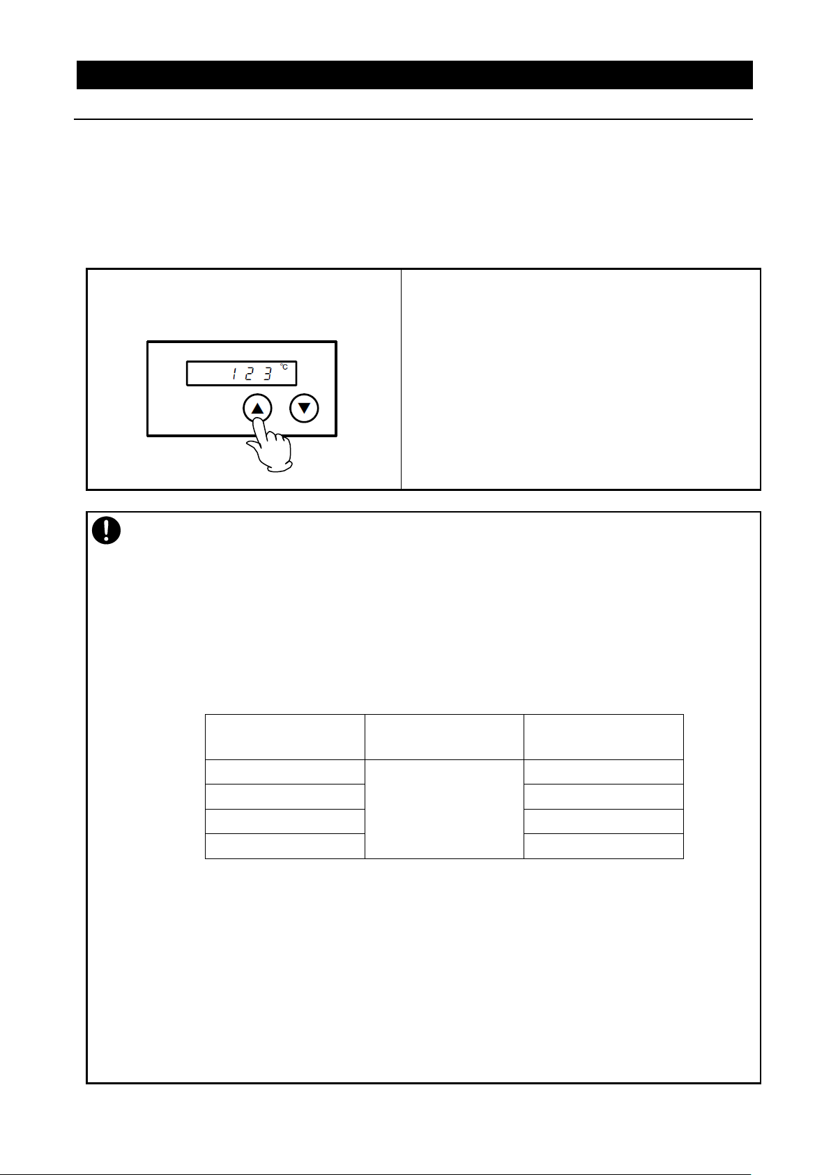
Set temperature on Independent
Overheat Prevention Device(IOPD)
※Set temperature with ▼▲ keys on its panel.
May stop its operation by activating Independent Overheat Prevention Device(IOPD) when the
difference between set temperature on IOPD and Target Temperature will be too close each other.
Must set IOPD temperature at least 20℃ higher than Target Temperature.
Note that the objective of this IOPD will not protect for samples but from overheating this
Equipment.
Factory settings and setting temperature ranges are as shown below:
Model
Set temperature at
shipment
Setting temperature
range
DF832
400℃
0℃~300℃
DF1032
0℃~300℃
DH832
0℃~400℃
DH1032
0℃~400℃
Control Chamber stable at required temperature first, and let IOPD setting temperature down
by 1℃ and then find out IOPD activating temperature, if IOPD will get to be activated at
required temperature.
Must wait for 5(five) seconds for the next 1℃ down of IOPD setting temperature, because its
function will be operated to need some times.
Display ER07 on Top Screen on Control Panel, if this IOPD is activated.
When you have set an operation temperature you want for IOPD , recording of the set
temperature takes several seconds and you need to wait for about five seconds before turning
the ELB off.
4. Operating procedure
Independent Overheat Prevention Device
This Equipment have redundant safety devices-1) Automatic Overheat Prevention (automatic reset)
function on the Controller, and -2) Independent Overheat Prevention Device(IOPD) with independent
power, circuit and sensor away from the Controller.
Main Relay of this Controller will be shut heater output power off when one of safety devices is
activated at Chamber internal temperature beyond its setting temperature.
Those functions will avail at Earth Leakage Breaker(ELB) ON(|).
46
Page 50

Never process any explosive, flammable samples and also samples contained with those
substances. It will cause fire/explosion. (See Chapter 13. List of dangerous materials on page
64.)
Be sure to check the withstand temperature before using a resin container. Using such a
container under a temperature beyond its withstand temperature will melt resin and a fire or an
explosion may result.
Turn immediately off Earth Leakage Breaker (ELB) of this Equipment and disconnect Power
Cord/Power Cable from receptacle or switch board of facilities, if smoke or strange smell is
generated from it by any chance.
Contact with local dealer or Yamato sales office and/or Yamato Customer service Center and
ask them to inspect it. If nothing is done to it, fire or electrical shock may result.
Never repair it by customer themselves to avoid any dangers.
Never insert any metal or easily flammable objects into the openings in the
chamber (radiation port, cable port, etc.). A fire, an electric shock or burning may
result.
If a foreign object has entered inside, immediately turn the ELB off and ask your
dealer, one of our sales offices or the customer service center for inspection.
Leaving as it is will cause a fire or an electric shock.
Take care not to touch samples when taking them in or out since inside the
chamber, internal wall of the door or samples are still hot for some time after
operation at a higher temperature. Be sure to put on heat-resistance gloves and
take extreme care for burning when handling samples.
When you attempt to open the door during operation at a higher temperature, never touch the
door since the internal chamber or the inside of the door are hot.
When the door is opened, the heater and the fan motor will stop for safety but note that the fan
motor will keep rotating from inertial and hot air will be blown out.
Note that if a fire alarm is installed around the unit, it may go off erroneously.
Never touch the door, the cable port or around the exhaust port during or immediately after
operation. They are hot and may cause burning.
5. Handling precautions
1. Never use any explosive or flammable substances.
2. Take extreme care when using a resin container.
3. Turn the ELB off when an abnormality occurs.
Warning
4. Do not put any foreign objects in the unit.
5. Take extreme care for handling of samples after operation at a higher temperature.
6. Take extreme care when opening the door during operation at a higher temperature.
7. Never attempt to touch hot surfaces.
47
Page 51

Do not climb on this Equipment. May cause personal injury and/or its failure by tipping it over
and being damaged.
Do not place any stuff on this Equipment. May cause personal injury falling it off.
Do not close up any flammable materials such as paper around it.
Turn immediately off the Breaker of the controller, when thundering and lightning start. If do not
so, it may cause fire or electric shock by the thunderbolt.
Do not keep Door open to cool the sample down quickly, etc. right after operation. May deform
Control Panel and cause failure of this Controller by heat wave from Chamber.
Do not process any samples containing corrosive chemicals even though Chamber is made of
stainless steel which this steel may be corroded by strong chemical acid, etc.
Operating temperature range will be room temperature+15℃~200℃(DF832/1032) and +15℃
~300℃(DH832/1032).
Never operate this Equipment at temperature out of its range. Operating the unit outside the
operating temperature range may cause a malfunction of the unit or an accident.
Do not set samples heavier than 30kg. Weight capacity of one shelf will be about 30kg
Spread samples evenly throughout on each shelf as many as possible.
Do not set excessive amount of samples on shelves. Chamber temperature may not be
controlled correctly. Must keep following procedure to control Chamber temperature correctly;
1) install the supplied shelves, 2) keep space between samples as wide as possible. 3) require
space opening more than 30% at each shelf.
Require space opening more than 30% at each shelf.
棚板
試料
30kg
Sample
Shelf
5. Handling precautions
1. Do not climb on the Equipment.
2. Do not place any stuff on the Equipment
3. Turn immediately off the Breaker of the Equipment at thundering.
4. Do not keep Door open after operation.
Caution
5. Do not process any corrosive samples.
6. Operate at the proper temperature.
7. Take extreme care when placing samples.
48
Page 52

Never set samples on bottom of Chamber. If samples will be processed at setting on bottom of
it, this Equipment may be not given as its full performance and become high temperature unlikely
and also cause failure.
Set samples on attached shelves properly installed on their brackets.
Do not allow samples to contact directly to side walls of Chamber.
Do not process humid specimens.
Water condensed inside the unit may cause an electric shock, a malfunction of the unit or
deterioration of HEPA filter.
Do not attempt to process wet samples.
The unit employs blowing to improve temperature distribution inside the chamber. When
processing powder or small samples, make sure that the sample will not scatter. A fire or an
electric shock may result if a flammable or a metal object enters the heater.
When processing smaller specimens, you can minimize circulating wind amount in the bath by
setting the variable wind speed to low, in which case the temperature performance will be out of
the warranty and the user needs to confirm the temperature characteristics.
Heating may take some time when the amount of samples is large or when processing samples
with a larger heat burden. Check the appropriate amount as necessary and set the sample. Also
note that the temperature indication may be unstable when processing heat-generating samples
(note that sample itself must be free of fear of explosion, inflammation or ignition).
Be aware of temperature sensor which it is installed on Chamber inside right portion and control
Chamber temperature. Therefore, if the amount of specimen is large or the equipment is in the
middle of heating, sensor detected temperature may not agree with temperature of the samples.
In particular, actual Chamber temperature will differ greatly from Read Temperature displayed on
Controller, right after opening or closing of this Equipment Door.
When a gap occurs between the temperature in the bath and the measured temperature requiring
adjustment, compensate temperature by referring to “P.39 Setting a calibration offset”.
When operation stopped from a power failure and then power recovers, the unit will automatically
resume operation.
See “P.40 Setting the recovery mode” for details.
Must be set temperature of Independent Overheat Prevention Device (IOPD).
Note that temperature of this IOPD must be set to temperature over 20℃ higher than Target
Temperature.
Refer to Chapter 4. Operating Procedure –“Independent Overheat Prevention Device” for how to
set and other cautions on page 46.
5. Handling precautions
8.Never set samples on bottom of Chamber.
9. Do not process humid or wet specimens.
10. Take care for processing of powder and small samples.
Caution
11. Note that the sample temperature and the measured temperature are not always
the same.
12. Check the following in terms of the recovery mode.
13. Be sure to set a temperature of the Independent Overheat Prevention Device.
49
Page 53

Be aware of Gasket on Chamber that is made from silicon rubber and may vaporize benzoic
acid, oil, etc. from volatile components of rubber used at their production during operation.
Ask specific Gasket made from fluoro-rubber for samples that are not compatible with those
chemicals.
Note that the rubber may be rusted or corroded by acids, alkaline, and halogenated solvent.
Material
Classification
Silicon Rubber
Fluoro-rubber
Hydrocarbons
Butane, Isooctane, Benzine,
Toluene, Xylene, Styrene, Diphenyl,
Pinene, Kerosene
Propane
Halogen,
Haloid
Hydrocarbon
Methyl Chloride,
Methylene Chloride, Chloroform,
Carbon Tetrachloride,
Trichloroethylene, Phlorobenzene,
Monochloronaphthalene, R-11、
R-12、R-21、R-22、R-113、R-114、Bromine
R-21、R-22
Ketone, Aldehyde
Methyl Ethyl Ketone,
Diisopropyl Ketone, Diclohexanon,
Acetophenone
Acetone, Methyl Ethyl Ketone,
Methyl Isobutyl Ketone,
Diisopropyl Ketone, Diclohexanon,
Acetophenone
Ester
Methyl Acetate, Ethyl Acetate,
Propyl Acetate, Butyl Acetate,
Amyl Acetate, Methyl Acetoacetate,
Butyl Acrylate, Ethyl Methacrylate
Methyl Acetate, Ethyl Acetate,
Propyl Acetate, Isopropyl Acetate,
Butyl Acetate, Amyl Acetate,
Ethyl Acetoacetate, Ethyl Acrylate,
Butyl Acrylate, Ethyl Methacrylate
Ether
Diethyl Ether, Dibutyl Ether,
Ethylene Oxide, Dioxane,
Epichlorohydrin, Tetrahydrofuran
Diethyl Ether, Isopropyl Ether,
Dibutyl Ether, Dibenzyl Ether,
Ethylene Oxide、Dioxane,
Epichlorohydrin, Furfural,
Tetrahydrofuran
Alcohol
Amyl alcohol
Multiple Alcohol
Derivative
Cellosolve Acetate, Butyl Cellosolve,
Triacetin
Show substances that they will erode silicon rubber (standard specification) and fluoro-rubber
Please contact with Yamato Scientific Customer Service Center for applicability of substances
other than those listed below.
【Caution】
5. Handling precautions
14.Take care for the following in terms of the Gasket on Chamber.
(special specification) for Chamber Gasket on Table 5.1.
Never process samples that will be contained these substances showing on its Table.
Table 5.1 - Typical substances eroding Gasket on Chamber
Caution
50
Page 54

Material
Classification
Silicon Rubber
Fluoro-rubber
Fatty Acid, Phenol
Acetic Anhydride, Oleic Acid,
Phenol Palmitate
Formic Acid、Acetic Anhydride,
Hydroquinone
Nitrogen Chemical
Compounds
Nitromethane, Nitroethane,
Nitropropane
Nitromethane, Nitroethane,
Nitropropane, Ethylenediamine,
Dimethylaniline, Ethanol amine,
Hydrazine, Triethanol Amine,
Dimethyl Formamide, Pyridine,
Piperidine
Sulfur and
phosphorus
compounds
Hydrosulfuric
Hydrosulfuric,
Tributyl Phosphate
Other Chemical
Compounds
Nickel Acetate, Lead Acetate,
Zinc Acetate, Tetraethyl Lead,
Vegetable Oil, Silicon Oil
Calcium Acetate, Nickel Acetate,
Lead Acetate, Zinc Acetate
Inorganic Solvent
Hydrochloric Acid, Nitric Acid,
Sulfuric Acid, Hydrobromic Acid,
Phosphoric Acid, Hypochlorous
Acid,
Chromic Acid, Perchloric Acid,
Sodium Hydrate
Sodium Hydrate,
Aqueous Ammonia
Check regularly Earth Leakage Breaker (ELB) and Independent Overheat Prevention Device
(IOPD) which they are key part/Device for the safety of this Equipment.
Refer to Chapter 6. Maintenance Method on page 53.
You cannot attain the set temperature if you fully open the exhaust damper. The set temperature
may not be attained even if the damper is not fully open and you need to check in addition to the
variable wind speed before starting operation.
When a measurement sensor or a probe is inserted into the cable port close the cable port cover
as much as possible and completely seal to any gaps with heat-resistant packing or sealant. If
seal is insufficient, the temperature characteristic, cleanliness or other performance will degrade.
When you operate the unit for the first time, the bonding material of the heat insulation material
may burn and generate odor, which, however, does not indicate a malfunction of the unit. Odor
will not generate as you continue to use the unit for some time.
5. Handling precautions
Caution
15. Never fail to perform periodic inspection.
16. Take care for the following when using the unit with the exhaust damper fully open.
17. Take care for possible degradation of performance when using the cable port.
18. Smoke may generate when you operate the unit for the first time.
51
Page 55

Do not attempt to touch the inside of the unit and the door when you open the door during
operation a higher temperature. Also note that a fire alarm if installed around the unit may react.
After operation at a higher temperature, the inside of the unit and the door as well as the
specimen will remain hot for a while. Take care not to touch those parts when putting or taking
out specimen. Be sure to put on heat resistant gloves to avoid burning.
Never apply any kinds of thinner and/or alcohol to wipe dirt off this Equipment.
May come paint off, and may change its color or deform its shape, Otherwise.
Note to turn Earth Leakage Breaker (ELB),off on the left side wall of this Equipment first, then
maintain it.
The fan motor keeps operating when the ELB is [ON(|)], the key is on, and the door is
closed.
Use the key to turn the fan motor off to stop it.
Do not put a thing on this container. Drop and cause the injury.
Be sure to read the operating instructions before using the unit.
5. Handling precautions
19. During operation at a higher temperature
20. About operation at a higher temperature
21. Never use thinner or alcohol to remove soil off the unit.
22. About the fan motor operation
Caution
23. About the top of the main unit
24. Be sure to read the operating instructions.
52
Page 56

Warning
● Be sure to turn off Earth Leakage Breaker(ELB) of this Equipment before daily inspection and
maintenance
● Inspect and maintenance this Equipment at ambient temperature on its Chamber.
● Never disassemble this Equipment.
Caution
● Wipe dirt off with wrung tightly soft cloth.
● Never clean this Equipment with benzene, thinner or scouring powder, or rub with a scrubbing
brush.
May cause deformation, degradation and/or discoloration.
● Inspect the ON and OFF functions of Earth Leakage Breaker(ELB).
・Prepare this Equipment for the inspection and connect Power Cord/Cable to receptacle or Switch
Board of facilities.
・Check ELB “OFF”, then turn ELB “ON(|)”.
・Press test button on ELB with ball-point pen etc. If ELB is shut down, ELB will be functional.
● Check operation of Independent Overheat Prevention Device(IOPD).
・Be operating this Equipment at appropriate Target Temperature on Fixed Temperature
Operation Mode.
・Set this IOPD working temperature down to approximately 10℃ lower than Read Temperature.
・Activate this IOPD and will be shut power off heater circuit in few seconds, and display “Er07” on
Top Screen, display warning sign “Overheat” on Bottom Screen, illuminate ERROR Lamp on
Control Panel, and buzz on the same time.
*Must check ELB and IOPD mentioned above prior to operate this Equipment for continuous long
hours or unmanned operation during night time before starting operation.
Inspect monthly.
6. Maintenance method
Daily inspection/maintenance
◆Contact immediately with local dealer, Yamato sales office, or Yamato Customer Service Center for
any questions.
53
Page 57

Warning
Caution
Do not operate this Equipment for the time being.
● Turn Earth Leakage Breaker(ELB) off and
disconnect Power Cord/Cable from receptacle
/switch board of facilities.
Scrap this Equipment.
● Do not leave this Equipment alone where
children may play and get at it.
● Before discarding the equipment, be sure to
remove the hinge and the door lock assembly
so that you cannot close the door hermetically.
Names of major parts
Material
Major components of the Equipment
External Structure
Chrome free electrogalvanized carbon steel sheet coated
w/Chemical-proof baking finish
Chamber
Stainless steel plate
Heat Insulator
Ceramic fiber + glass wool
Door packing
Silicon rubber
Major components of electrical parts
Switch and Relay
Composite of resin, cupper and other materials
Operation Panel
Polycarbonate resin
Printed Circuit Boards
Composite of fiber glass and other materials
Heater
Stainless steel pipe
Power Cord/Cable
Composite of synthesized rubber coating, cupper, nickel and other
compound materials
Wires
Composite of fiber glass, fire-retardant vinyl, cupper, nickel and
other materials
Stickers
Resin materials
Sensor (K thermo-couple)
Stainless steel and others
7. Long storage and scrap
When not using the Equipment for a long time / when scrapping
Matters to consider when scrapping the Equipment
Pay attention always to the preservation of the global environment.
We, as Yamato Scientific Co., Ltd. highly recommend taking this Equipment apart as far as possible
for separation or recycling to contribute to the preservation of the global environment according to the
specified garbage collection method stipulated by each local government..
List major components and their materials for this Equipment as follows:
54
Page 58

Error
Display
Error Code Name
Causes and their solutions
ER01
SENS
Sensor Failure
Fail in temperature sensor.
Open circuit on temperature sensor line.
Detect temperature out of its designed range.
Contact with local dealer or Yamato Customer Service Center.
ER02
TRIAC
TRIAC short circuit error
Short on TRIAC circuit.
Fail on Current Transformation (CT) sensor.
Contact with local dealer or Yamato Customer Service Center.
ER03
HEAT
Heater Line
Disconnection
Heater Line Disconnection
Fail on Current Transformation (CT) sensor.
When the source voltage has dropped,
contact with local dealer or Yamato Customer Service
Center.
ER04
FAN
Fan motor Failure
Malfunction of the fan motor
The fan has stopped.
Contact the general customer service center.
ER07
OHEAT
Independent
Overheat Prevention
Device(IOPD)
activated
Activate Independent Overheat Prevention Device (IOPD).
Turn ELB on again and check both Chamber temperature and
setting Temperature of IOPD.
Contact with local dealer or Yamato Customer Service Center,
if this Equipment is not energized at ELB on.
ER10
RELAY
Main Relay Contact
melted
Check at turning ELB on again:
Melt down the contact point of Main Relay.
Fail on Current Transformation (CT) sensor(s).
Contact with local dealer or Yamato Customer Service Center.
ER14
RAM
RAM Failure
Reduced capacity or
end of use life of the
backup battery
Check at turning ELB on again:
RAM Failure:Reset power once.
Reduced capacity or end of use life of the backup battery:
Contact with local dealer or Yamato Customer Service Center,
if this error cannot be reset by ELB on.
Must be replaced backup battery.
8. When a trouble occurs
Message error table
Show the error codes on Table 8.1 below.
Buzz and stop its operation at occurring errors on this Equipment.
Pressing any key (except for the key) will stop the buzzer sound. When three minutes have passed
as it is, the buzzer starts to sound again.
The Top screen shows an error code and the Bottom screen shows the error name. Note the error code,
immediately turn power off and stop operating the unit.
Table 8.1 Table of Error Code
55
Page 59

Error
Display
Error Code Name
Causes and their solutions
ER15
EPROM
EEPROM Failure
Check at turning ELB on again:
Change its data code on EEPROM.
Contact with local dealer or Yamato Customer Service Center,
if this error cannot be reset by ELB on.
Must be replaced backup battery.
Temperat
ure in the
chamber
DOOR
Door open
Door is open.
This is not a malfunction.
When you open the door, [DOOR] flashes on the Bottom
screen, the heater circuit is shut off for safety and the fan
motor will stop. Closing the door will eliminate the [DOOR]
indication, the heater circuit will recover automatically and
the fan motor starts.
Leaving the door open for about 2 minutes will activate the
buzzer. Pressing any key (except for the key) will stop
buzzer sound.
Leaving the door open will activate the buzzer after about 2
minutes.
8. When a trouble occurs
Message error table
56
Page 60

Phenomena
Causes
Solutions
Do not display current
time on Bottom Screen
at Earth Leakage
Breaker (ELB) ON.
・ Do not supply power.
・ Fail ELB.
・ Fail Controller.
・ Check connection to power
supply and apply power.
・ Replace ELB.
・ Replace Controller.
Do not display
anything on both Top
and Bottom Screen at
Controller Power key
pressed and held.
・ Fail supplied power.
(Required Voltage ±10%)
・ Fail Controller.
・ Connect to adequate power
supply.
・ Replace Controller.
The fan motor will not
operate even if the
power key of the
controller is pressed.
・ Fan motor malfunction
・ The door is open.
・ Replace the fan motor
・ Close the door.
Do not rise Chamber
temperature.
・ Activate IOPD and /or Self-
diagnosis Function built–in
on Controller, and shut heater
circuit down
(Error code displayed).
・ Refer to “Cause and their
solutions” of Table 8.1 – Error
Code on page 55.
Display temperature
unstable.
・ Fluctuate ambient temperature
heavily.
・ Fail supplied power.
(Required Voltage ±10%)
・ Fail Controller.
・ Fail Temperature Sensor
・ Be affected by samples.
・ Review its location.
・ Connect to adequate power
supply.
・ Replace Controller.
・ Replace Temperature Sensor.
・ See “P.49 15. Take care for
processing of powder and small
samples”.
8. When a trouble occurs
Troubleshooting
Show troubleshooting guide on Table 8.2.
Refer to “Cause and their solutions” of Table 8.1 – Error Code on this Chapter “Massage Error Table” at
Table 8.2 - Troubleshooting Guide
Contact with local dealer or Yamato Customer Service Center phenomena other than Table 8.2 above.
57
Page 61

Request to repair partsは
Keep Warranty Card with care.(attached separately)
Guarantee for maximum storage period of repair parts.
See Warranty Card or caution rating nameplate
on this Equipment.
(See Chapter 3. Names and functions of each
part “on page 7 for details.
9. After sales service and warranty
Request to repair parts
When any abnormality occurs immediately stop operation, turn the controller power and the ELB off and
contact your dealer, one of our sales offices or the customer service center.
Require the following information for repair.
● Model name of Yamato products
● Serial Number
● Date (year/month/date) of purchase
● Description of trouble in detail as possible
Be sure to present the warranty card to Yamato service representative.
● Keep Warranty Card with care.
Warranty Card would be given by local dealer or one of Yamato sales offices.
Date of purchase of this Equipment and other information should be filled in Warranty Card.
Please send Warranty Card to Yamato Customer Service Center(Yamato CSC) by facsimile
described Fax number in the left top corner of it.
Then, keep its Card with good care.
● Repair this Equipment for free of charge according to the contents on Warranty Card.
Warranty period is 1(one) year from date of purchase.
● Consult with local dealer, one of Yamato sales office or Yamato CSC for any repair after warranty
ended.
Charged repair service of this Equipment will be available on customer’s request when it can be
maintained functional by its repair.
Guarantee that maximum storage period of repair parts will be 7(seven) years after end of their production,
Constant Temperature Precision Oven(Fine Oven).
Repair parts will be defined the parts to maintain this Equipment performance.
58
Page 62

Product Name
Constant Temperature Precision Oven(Fine Oven)
Model Name
DF832
DF1032
DH832
DH1032
System
Forced wind circulation and ventilation
Operating environment
temperature range
5℃~35℃
Power supply
3 phase AC220V
13.5A
3 phase AC220V
17A
3 phase AC220V
20A
3 phase AC220V
28A
Common to 50/60Hz, operating voltage range:±10%
Performance
Temperature
Control Range
Room temp.+ 15℃~200℃
Room temp.+ 15℃~300℃
Temperature
fluctuation ※2
±1.5℃ (at 200℃)JIS C60068
±1.5℃ (at 300℃)JIS C60068
Temperature
slope
12℃ (at 200℃)JIS C60068
18℃ (at 300℃)JIS C60068
Temperature rise
time
Approx.60min.
Approx.60min.
Composition
Exterior
Chrome-free electro-galvanized steel plate Chemical proof baking finish
Chamber
Stainless steel plate
Insulation Material
Glass wool
Door
Single swing (left side)
Heater
Stainless steel pipe heater
Heater capacity
4.5kW
6.0kW
6.9kW
9.0kW
Fan (motor)
Stainless steel axial flow fan (capacitor motor 20W Type1032×2)
Cable port
I.D. :φ30mm(back)
Exhaust port
I.D.:φ80mm(back)
Controller
Type
V-shaped controller
Temperature Control
Method
PID Z control
Temperature setting
method
Digital setting with ▲/▼ keys.
Temperature
Display Method
Top Screen (Chamber):Green 4-digit LED Digital Display (Resolution:
1℃)
Bottom Screen:Orange 5-digit LED Digital Display (Resolution:1℃)
Other displays
LED indicates temperature patterns for heating/stable/cooling
Timer
Settable between 1 minute and 99 hours 59 minutes: duration operation
24 hour setting: time operation
Operating function
Fixed temperature operation
Program operation(Maximum 99 steps, up to 99 patterns, the repeat operation
function)
Duration/time select timer operation function (Fixed temperature operation auto
start/auto stop/quick auto stop, program operation auto start)
※1
10. Specifications
Specifications
59
Page 63

Model
DF832
DF1032
DH832
DH1032
Controller
Additional
function
Variable wind speed function
Power on and Operation Time Integrating Function(up to 65,535 hours);
Calibration Offset; Monitor Display of Integrated Power Consumption, Total CO2
Emission, and Heater operating Output; Power Recovery Mode; Save and
Access of Operater’s Setting Information;
Heater Control
Triac with Zero-cross Control
Sensor
K type Thermocouple double sensor
(for temperature control and independent overheat preventive device)
Safety Device
Controller
Self-diagnosis Functions (Temp. Sensor Failure Detection, TRIAC Short Circuit,
Heater Line Disconnection, Fan Failure Detection, Main Relay Contact Melted,
Automatic Overheat Prevention), Key Lock Function
Earth Leakage
Breaker(ELB)
20A
30A
30A
40A
Leak Current/Short Circuit/Over-current Protection,
Rated Sensitivity Current 30mA
Box switch on the control assembly (interlocked with the ELB)
Independent
Overheat
Prevention
Device(IOPD)
Set Temperature Range:0~400℃
Door switch
Door open: fan motor and heater circuit OFF
Door close: fan motor and heater circuit ON
Standard
Internal
dimensions
Width
※3 Depth
Height
800mm
800mm
800mm
1000mm
1000mm
1000mm
800mm
800mm
800mm
1000mm
1000mm
1000mm
External
dimensions
Width
※3 Depth
Height
1500mm
1015mm
1330mm
1700mm
1215mm
1510mm
1500mm
1015mm
1330mm
1700mm
1215mm
1510mm
Internal capacity
512ℓ
1000ℓ
512ℓ
1000ℓ
Weight
Approx. 320kg
Approx. 420kg
Approx. 320kg
Approx. 420kg
Number of
tiers/shelf support
pitch
10tiers /76mm
10tiers /98mm
10tiers /76mm
10tiers /98mm
Withstand load of
each shelf board
Approx. 30kg/piece
Acces
-
sories
Shelf board and
shelf support
Stainless steel wire
3 pieces
Shelf support;6
Instruction
Manual
1 copy
Warranty card
1 copy
Article
※1 Performance data has been measured at the conditions: Rated source voltage, 3 phase AC200V;
room temperature of 23℃; relative humidity of 65%RH±20%, damper fully open, cable port fully
closed, variable wind speed setting at 10 and no load.
※2 The value is calculated by dividing the measured value to JIS by 2.
※3 Protrusions are excluded.
10. Specifications
Specifications
60
Page 64

3φAC220V
50/60Hz
12. Wiring diagram
DF/DH832 Wiring diagram
61
Page 65

3φAC220V
50/60Hz
12. Wiring Diagram
DF/DH1032 wiring diagram
62
Page 66

Symbol
Nomenclature
Symbol
Nomenclature
ELB1
Earth Leakage Breaker(ELB)
PLB
V type Planar Board
T1,2,3
Terminal Block for wiring
PIO
V type Display Board
SSR1,2,3
Solid State Relay
OH1
Independent Overheat Prevention
Device
H1
Heater
PI1,2
Photo Coupler
CT1,2,3
Current Sensing Element
DS1
Door Switch
X1
Main Relay
TH1-1
Sensor for temperature control
FM1,2
Fan Motor
TH1-2
Sensor for Independent Overheat
Prevention Device
CR1
Spark Killer
12. Wiring Diagram
Wiring diagram part symbols
63
Page 67

Never process any explosive, flammable samples and also samples
contained with those substances.
Explosive
Substance
①Nitroglycol, Glycerine trinitrate, Cellulose Nitrate and other explosive nitrate esters
②Trinitrobenzen, Trinitrotoluene, Picric Acid and other explosive nitro compounds
③Acetyl Hydroperoxide, Methyl Ethyl Ketone Peroxide, Benzoyl Peroxide and other organic
peroxides
④Metallic Azide, including Sodium Azide, etc.
ExplosiveSsub
stances
①Metal “Lithium” ②Metal “Potassium” ③Metal “Natrium” ④Yellow Phosphorus
⑤Phosphorus Sulfide ⑥Red Phosphorus⑦Phosphorus Sulfide
⑧Celluloids, Calcium Carbide (a.k.a, Carbide)⑨Lime Phosphide⑩Magnesium Powder
⑪Aluminum Powder ⑫Metal Powder other than Magnesium and Aluminum Powder
⑬Sodium Dithionous Acid (a.k.a., Hydrosulphite)
Oxidizing
Substances
①Potassium Chlorate, Sodium Chlorate, Ammonium Chlorate, and other chlorates
②Potassium Perchlorate, Sodium Perchlorate, Ammonium Perchlorate, and other perchlorates
③Potassium Peroxide, Sodium Peroxide, Barium Peroxide, and other inorganic peroxides
④Potassium Nitrate, Sodium Nitrate, Ammonium Nitrate, and other nitrates
⑤Sodium Chlorite and other chlorites
⑥Calcium Hypochlorite and other hypochlorites
Flam
mable
Substances
① Ethyl Ether, Gasoline, Acetaldehyde, Propylene Chloride, Carbon Disulfide, and other
substances with ignition point at a degree 30 or more degrees below zero.
②n-hexane, Ethylene Oxide, Acetone, Benzene, Methyl Ethyl Ketone and other substances with
ignition point between 30 degrees below zero and less than zero.
③Methanol, Ethanol, Xylene, Pentyl n-acetate, (a.k.a.amyl n-acetate) and other substances with
ignition point between zero and less than 30 degrees.
④Kerosene, Light Oil, Terebinth Oil, Isopenthyl Alcohol(a.k.a. Isoamyl Alcohol), Acetic Acid and
other substances with ignition point between 30 degrees and less than 65 degrees.
Combustible
Gas
Hydrogen, Acetylene, Ethylene, Methane, Ethane, Propane, Butane and other gases combustible
at 15℃ at one air pressure.
13. List of dangerous substances
Excerpt from Table 1, Hazardous Substances, of Cabinet Order of the Occupational Safety and Health
Law (substances related to Articles 1, 6, and 9)
64
Page 68

Model name
Date of
preparation
(Y) (M) (D)
Program pattern number
Prepared by
01
02
03
04
05
06
07
08
09
10
11
12
13
14
15
16
17
18
19
20
21
22
23
24
25
Pattern
number
Step
Set
temperature
Time
Repeat
dstn
Number
of
repetitions
Wait
Wind
speed
level
End
P**:00
P02:
**
TEMP
TIME
REP
REP
WAIT
FAN
END
:ST
(℃)
Hr:
Min
STEP
COUNT
ON/OFF
1~10
01
:
02
:
03
:
04
:
05
:
06
:
07
:
08
:
09
:
10
:
11
:
12
:
13
:
14
:
15
:
16
:
17
:
18
:
19
:
20
:
21
:
22
:
23
:
24
:
25
:
100
200
300
0
300
200
100
0
Set temperature
(℃)
(℃)
Programming sheet Control №
Program pattern
Step №
65
Page 69

Yamato Scientific America,
Inc.
925 Walsh Avenue, Santa Clara,
CA 95050, U.S.A
http://www.yamato-usa.com
Toll Free: 1-800-2-YAMATO(1-800-292-6286)
Limited liability
Be sure to use this Equipment strictly following the handling and operating instructions
in this Instruction Manual.
Yamato Scientific Co., Ltd. assumes no responsibility for accident or malfunction caused
by use of this Equipment in any way not specified in this Instruction Manual.
Never attempt to perform matters prohibited in this Instruction Manual.
Otherwise, unexpected accident may result.
Notice
● Descriptions in this Instruction Manual are subject to change without notice.
● WE, as Yamato Scientific Co., Ltd. will replace this Instruction Manual with missing
page or paging disorder.
Operation Manual
Constant Temperature Precision Oven(Fine Oven)
DF832/1032
DH832/1032
First Edition: 22 March 2016
66
 Loading...