

Page 1

INSTBUTIONS
AIJU8TING
"YAMATO"
SAFEn
AMI
STITCO
OVERIOCA
OPERATING
DGZ-Oei
HAGRINE
KONDO
SEWING
MACHINE
CO.,
LTD.
Page 2

QassesofDCZ type
361
series
DCZ-361Y-
DCZ-361A
DCZ-361C
DCZ-365YDCZ^365A
DCZ-365C
DCZ-366Y
DCZ-366ADCZ-366C
DCZ-367YDCZ-367A-
DCZ-367C
DCZ-368A-
Needle spacing:
Needle spacing
-
Needle spacing
-
Needle spacing
Needle spacing
-
Needle spacing
-
-
Needle spacing
Needle spacing
Needle spacing
-
Needle spacing
Needle spacing
Needle spacing
-
Needle spacing
2.4 mm.
3.2
mm.
5.0
mm.
2.4 mm. For safety stitdiingand ruffling.
3.2
mm.
5.0
mm.
2.4 nun. For safety stitching and ruffling with insert a decorativepiping.
3.2
mm.
5.0
mm.
2.4 mm. For safety stitching and rufflingwith attached tape.
3.2
nun.
5.0
mm.
3.2 mm. For inserting a tape inside the seam for binding pocket lining and
safety stitching.
Figures and symbols on Model Number Plate
For
safety stitching woven fabrics and knit goods.
Uses
sameasabove.
Uses
sameasabove.
Uses
sameasabove.
Uses
sameasabove.
Uses
sameasabove.
Uses
sameasabove.
Uses
sameasabove.
Uses
sameasabove.
DCZ-361
• '
A-Dl
rr
Type
DCZ
Class
361
361
361
365
365
365
366
366
366
No.
Y
A
C
Y
A
C
Y
A
C
Needle spacing
(mm)
2.4
3.2
5.0
2.4
3.2
5.0
2.4
3.2
5.0
Presser
Divided
two
Two
Foot
into
sections
sections
presser foot
and ruffling
attachment
Two
sections
presser foot
and ruffling
attachment
with
insert
decorative
piping
Feed
P =
(differential feed
impossible)
D =
(differential feed
possible)
a
Mechanism
Plain
Differential
No.
1
2
1
2
3
1
2
1
2
3
1
2
1
2
3
Throat
5.0
5.5
5.5
6.0
9.0
5.0
5.5
5.5
6.0
9.0
5.0
5.5
5.5
6.0
9.0
Seam
Plate
Width
(mm)
^
^
^
^
^
^
6.5
7.0
7.0
8.0
11.0
6.5
7.0
7.0
8.0
11.0
6.5
7.0
7.0
8.0
11.0
367
Y
2.4
Two
sections
presser foot
and ruffling
367
367
368
A
C
A
3.2
5.0
3.2
attachment
with
attached
tape
Two
sections
presser foot
(special)
1
5.0
'v.
'N#
6.5
7.0
7.0
8.0
11.0
7.0
8.0
5.5
2
5.5
1
2
6.0
.3
9.0
1
5.5
6.0
2
Page 3

Needle Space
Specifications for DCZ-361
Appellation ; Super HighSpeed Safety Stitch Machine
Overalllength : 375 mm.
Overall
Overall Height: 290 mm.
Net Weight: 25 kg.
Construction; Dust-proof,oil-tightand entirely enclosed.
Seam
Used:Overseaming
Speed:
width
:
225
mm.
Specifications : El3, El3A and D12(SafetyStitch-JIS
and
Maximum
overedging
: 5500stitchesper minute
woven
and
Economical: 5000-5200 stitchesper minute
Stitch Length :
Seam
Width:Overall
Presser
Foot
Differential
Lubrication:Clean
Principal
Recommended
Bearings:Ball
5-26
stitchesper inch
seam
width
consists
Needle space : 2.4 imn, 3.2 mm. and 5 mm.
Overedging
Note
Lift:
Ratio
: 1 :
width :
: 2.5- 5.5
4
mm.atthe
2.7atthe
mm.
maximum
maximum
oilisconstantly
anda
pressure
Oil:
regulating
and
needle
"Yamato"SFOil
ofthe
3-4
mm.(standard)
width
maybemadebychanging
force-fedtoall
valve.
bearings
and
Seam
knit
fabrics,
needle
space
parts
In addition,
oilless
bearings
Width
B9070)
attaching
partandthe
ata
given
splashed
sleeves
and
side
seaming.
overedging
throat
plates
pressurebymeans
and
part.
presser
ofa
gear
oilisalsoutilizedfor lubrication.
abimdantly
used.
foot
pump
finger.
unit
Needle
Bar
Stroke
: 25
nun.
Needles
: DCX 1 for right needle
DM X 13
Needlesizesavailable : Nos.9, 11 and 14.
for
left
needle
Page 4
ThroatHates :
There
are
several
kinds
of throat
plates
with
various
types
ofstitch
tongues
fordifferent
uses.
Presser
Feed
Differential
Feed Dogs : Standard number
Looper
Knives : Flat knives, 8 mm. in breadth and 1.5 mm. in thickness, used. There are two kinds of
CapacityofOil Reservoir : 1000c.c.
Foot
Mechanism:Presser
coil and plate. Foot plate isdivided into two parts - back and front-and eachofwhich
is hinged.
Regulating
Mechanism:Feed
Feed
Mechanism:Differential
Single
(Plain)feed or two feed(Differential)
Movement:Loopers
special steel and Tangsten Carbide alloy.
foot
turning the hand wheel by hand.
a lever lengthwise.
of
teeth is 16 to the inch.
makeaspecial
maybeswung
amountisregulated
feed
curve
outto
amountiseasily
movement
the
easily
dogs.
best
left.
Pressureonfootisregulatedbytwo
from
the
outsidebypushing
adjusted
suitable
from
for
the
outsidebymanipulating
high
speed
sewing.
down
springs
abutton and
kinve:,
•
j
Installation:Submerged.
fastened to the bottom plate with wood screws.
The
machine
headissettledonrubber
cushions
fixedtothe
base
plate
wluchisagain
Page 5

GeneralInstructions for
1. SewingSpeed
The
maximum
daily
operationis5000-5200
In
startinganew
minute
2.
Installation
Fig.1shows
one.
But
the
submerged
your
order
speed
machine,itis
for
about
200
the
measurements
the
non-submerged
installationinstock
for
them
Using
DCZ-361
for
this
machineis5500
stitches
advisabletorunitat
hours
(i.e.,
about
for
installing
installationisalso
for
willbepromptly
Center
lineofMotor
stitches
per
minute.
one
month),asit
this
practised.Aswe
customers
executed.
per
minute
the
optimum
will
machine.
who
The
wishtohave
but
the
speed
greatly
help
standard
have
these
optimum
after
operatingitat
prolong
position
always
the
articles
Base
speed
recommended
its
life.
for
installationisa
tables
and
together
Plate
with
Screw
4500
stitches
ancillary
the
machines,
for
per
submerged
parts
for
Center
line
of
Machine Pulley
Hole
SupportingBoardBolt
Base
Plate
Supporting Board
for
Base
Plate
Center
lineofMachine Belt
Rubber
Cushion
Base
Plate
Page 6

3.
Motor
and
Belt
Use400 W.(1/2 HP)clutch motor and K-type V-veltfor drivingthis machine. Theproper sizeof a motor
pulleysuitable for the rated
R.P.M.
may be pickedout from Table 1 and Fig.2.
Table
1
Machine Pulley
R.P.M.
Machine
4.500
5.000
5.500
of
Head
Outside
50
90
100
110
DiameterofMotor
cycles
mm.
mm.
mm.
60 cycles
75
mm.
85
mm.
90
mm.
It is most ideal to use a pulley with the outside diameter
of the calculatedvalue. But wehavespecified standardiz
ed motor pulleys which are.easilyprocurable in the
market
calculated
stepsof5 mm.
and
whose
outside
value
as these pulleysare made generally in
diameter
measures
near
the
Standard
Pulley
Fig. 2
Outside
of
Motor Pulley
Diameter
4
0"
8 nun
Cross
Section
K type V-belt
Oisin
of
Page 7

4.
Lubrication
As
the oilhasbeencompletely drained from the
fore
starting operation
level
comesup to the upper lineHon the oil
Be
sureto check the oil
fresh oil should be replenished. After replenishing, replace the screw.
In order to keep the machinelife longer,it is
for
250
hoursorso.
7
"O
through
gauge
01L_(2>
theoil hole
before starting operation everyday. If the oil
machine
removing
gauge
advisable
beforeshipment,be sureto
the
screw
shown in Fig.4.
to changeoil completely after operatinga new machine
indicated by "OIL"
level
fill
the oil
reservoir
mark.
Filloil until the oil
isbelow the lower line L,
(S)
DRAIN
be
Fig. 3
To change oil, drain the used oil out of the reservoirby removingthe drain screw(A, Fig.4) situated below the
balance wheel. The drain hole is indicated by the mark
Anoil filter net is fixed to the pump F insidethe machine. Clean this net and the insideof the base two or three
times a year. To do this, the base must be separated from the machine frame. To remove the base, drain the
oil completely out of the reservoir, tip the machine backwards and removethe set screws. When the cleaning
hasbeen
between
5. Rotating DirectionofBalance Wheel
The
6.
Needles
DC
proper
isthe standard
finished,
the
balance
X I
needleisused
size
fix the
base
machine
wheel
needles
base
and the
should turn to the right or
for the right
shouldbe selected according to the kind of work to be undertaken.
size
for
sewing
togetherwith the
light
machine,
needle
weight
theseoil can bedrainedby
andDMX 13 for the left needle. There are manysizesfor them and
fabrics,
clockwise
packings
#11 for
"DRAIN".
to the
when
facing
medium
machine
the balance
weight
securely.
removing
Fig. 4
When
thescrewC.(Fig.4)
wheel.
and #14 for
the oil stay the
Generally
heavy
speaking,
weight.
space
#9
7. Setting Needles
Turn
the
balance
litter Ain theairov
set
screwC.insert
and then tigliien the screw.
wheel
direction
the
away
needle
from
youuntilthe
and
swing
inthe
holderasfarasit
out the
needle
bar
reaches
presser
foot Bto the left as
willgowithitscarfed
the
highest
position,
showninFig.5.Loosen
side
(nota
pull
long
the
grove)
presser
the
at the
bar
needle
back
Page 8

8. Threading
Thread the machine as shown in Fig. 6.
A - Right-hand needle thread for cveriock seam
B -
Left-hand
needle
thread
for
double
C — Upper looper thread for overlook seam
D — Lower looper thread for overlook seam
E — Looper thread for double ohainstitoh seam
chainstitch
seam
DMX
DCxl
13
Ww
a
Page 9

9.
Thread
Tension
Figs.7and
itisat
the
To
make
7-1
height
the
for
show
below
tension
moveBdownwardsalittle.
thread breakage.
In
almost
all
cases,
the
Double
the
the
onthe
needle
Chainstitch
relation
highest
needle
Seam
between
the
pointofthe
thread
lighter,
Butitshouldbenoted
tension
maybesatisfactorily
needle
guide
move
that
thread
guidesAandB.The
Aby1/4of
this
too
its
thread
guideBupwardsalittle
much
raisingorloweringofthis
adjustedbyturning
stroke
position
(sameasthe
the
tension
ofBisright
needle
bar
andtomake
guide
adjusting
stroke).
often
cap.
when
heavier,
causes
About
1/4
of
Stroke
StrokeofThread
Eyelet A
A (Highest
Dead
Point)
Fig. 7
Needle
threadinits
highest position
/
,/
H
Needle
threadinits
lowest position
A (Lowest Dead Point)
Fig. 7-1
Page 10

10. To Thread the Upper Looper
To beginwith, open the front cover towards you.
looper
at A
from
position as
shown
underas
in Fig. 9
showninFig.
and
then
thread
Move
8. Turn the
the
looper
the upper looper to the lowestposition, thread the
balance
at B.
wheel
untilthe
looper
moves
Highest Position
up to the
highest
11. Various
Fig,10-
Fig.11-
Lowest
Stitch
Stitch
Stitch
Position
Fig. 8
Formations
formationinordinary
overedging
formationinblindstitch
seam
hemming
seam
(with
(with
three
two
Fig. 9
threads)
threads)
Fig.12-
Fig.13-
Fig.14-
Fig.15-
Stitch
formation
looper
(withtwo
Stitch
formationintwo
ing
(the
upper
Stitch
formationintwo
ing
(the
upper
DCZ-221)
Stitch
formationintwo
overedging(DCZ-36I)
whenaspreaderissubstituted
threads)
looper
looper
needle,
four
thread,
threadiscaughtbyboth
needle,
four
thread,
threadiscaughtbythe
needle,
five
thread,
double
for
the
upper
safety
stitch
overedg
needles-DCZ-220)
safety
stitch
overedg
right
needle
only
~
safety
stitch
Page 11
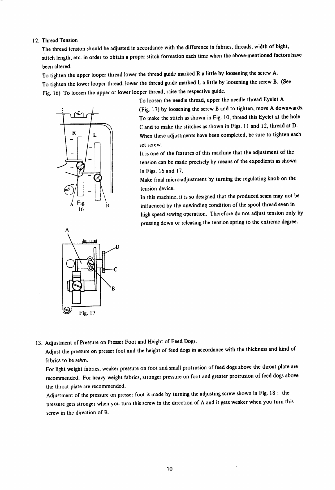
12.
Thread
Tension
The
thread
stitch
length,
been
altered.
To
tighten
To
tighten
Fig.
16)Toloosen
tension
shouldbeadjustedinaccordance
etc.inordertoobtainaproper
the
upper
looper
thread
lower
the
lower
looper
thread,
the
upperorlower
lower
looper
with
the
differenceinfabrics,
stitch
formation
the
thread
guide
the
thread
guide
thread,
To
loosen
(Fig.
To
make
Cand to make the stitches asshownin
When
set
screw.
It isone of the features of this machine that the adjustment of the
tension
in Figs. 16 and 17.
Make
tension
In this
influencedbythe
high
pressing
raise
the
17)byloosening
the stitchas
these
adjustments
canbemade
final
micro-adjustmentbyturning
device.
machine,
speed
sewing
downorreleasing
each
time
when
markedRalittlebyloosening
markedLalittlebyloosening
the
respective
needle
thread, upper the
the
showninFig.
preciselybymeans
it isso
unwinding
operation.
guide.
screwBandtotighten,
have
been
designed
condition
Thereforedonot
the
tension
threads,
the
above-mentioned
needle
widthofbight,
factors
the
screw
A.
the
screwB.(See
thread Eyelet A
moveAdownwards.
10,threadthis
Figs.11and 12,thread at D.
completed,besuretotighten
ofthe
the
that the
produced
ofthe
springtothe
Eyelet
at the
expedientsasshown
regulating
spool
seam
thread
adjust
extreme
knob
may
tension
onthe
not be
even
only
degree.
have
hole
each
in
by
I
\mm\i
Fig. 17
13.
AdjustmentofPressureonPresser
Adjust
the
pressureonpresser
fabricstobe
For
light
recommended.
the throat plate are recommended.
Adjustmentofthe
pressure
screwinthe
sewn.
weight
fabrics,
For
gets
stronger
directionofB.
weaker
heavy
pressureonpresser
when
Foot
foot
and
pressureonfoot
weight
fabrics,
you
turn
and
HeightofFeed
the
heightoffeed
and
stronger
pressureonfoot
Dogs.
dogsinaccordance
small
protrusionoffeed
footismadebyturning
this
screwinthe
directionofA
and
the
adjusting
with
dogs
greater
screw
anditgets
the
thickness
above
the
throat
protrusionoffeed
showninFig.18.
weaker
when
you
and
dogs
turn
kind
plate
above
the
this
of
are
10
Page 12

Pressure Regulating
Screw
Fig. 18
The standard settingofthe height of feed dogs is obtained when the bottomofthe teeth islevel with the
upper
surfaceofthe throat plate at its highest position. Almost all fabrics may be satisfactorily sewn in this
condition.
14. Adjustment of Bight Width
(1) To increase the.bight width (See Fig. 19)
Loosen the upper knife holder screw B, move the holder in the directionofthe arrow 0 as desired and
ti^ten
the screw B. Loosen the lower knife holder screw A and move the holder in the direction of O
until the lower knife D is closely pressed against the upper knife F with an appropriate pressure by the
actionofthe spring in the lower knife holder.
(2) To decrease Bight Width (See Fig. 19)
Loosen the lower knife screw A, move the holder towards P as desired and tighten the screw A. Then
loosen the upper knife holder screw B, move the holder towards P until the upper knife F gets in close
touch with the lower knife D and then tighten the screw B. Loosen the lower knife holder screw Aagain
and let the lower knife D come into close contact with the spring-pressed upper knife F. The sharpness
of the knives is easily checked by cutting a piece of thread inserted between the upper and lower knives
turning the balance wheel by hand.
To replace the upper knife, loosen the screw G and to replace the lower knife, loosen the screw H.
Of course, besides the distance between the left needle and the cut edge, the sizeof the stitch tongue of
the throat plate has much to do with the bight width.
p*
>0
Details
11
Fig. 19
for
L
Page 13

15. To Regulate Stitch Length
Thestitch lengthmaybe
However,on this machine, our standard feed dogs are fitted with. Therefore, in case of any stitch length
longer
than 8 stitches per inch is required, refer to our Instruction for adjustingmachine,paragraph8.
To
regulate
the stitchlength,
regulated
follow
from
5 to 22 stitchesper inch(25.4 mm.)
the next procedure. To
begin
freely.
with,push the button A(Fig. 20) lightly
until it touches the regulator. Keep pushing the button lightly with the left hand and turn balance wheel away
from you with the right hand until this button falls into a dent on the regulator. Then push in the button A
strongly and continue to turn the balance
wheel
with stronger hand. Thebalance
wheel
hasthe graduations
indicatingthe stitch numbers per inch on its periphery. Turn the balancewheeluntil you can find the graduation
showing
then
It should be noted that sometimes a
inch from the graduated
ratio, etc. In such cases, check the actual numberofstitches per inch and set the balance wheel to a proper
graduation.
the
release
desired
the
left
numberof stitchesper inch to coincide with the arrow-shaped feed regulatorpointer and
hand.
given
figure
according to the
graduationactually
sewing
gives
somewhatdifferent number of stitches per
condition - kind and thickness of the fabrics, differential
Fig. 20
16. To adjust Differential Ratio
Loosen the milled screw A (Fig. 21), move the lever B lengthwise to a desirable position and tighten the screw A.
The differential ratio between the main feed dog (rear feed dog) and the differential feed dog (front feed dog)
may be freely selected from I : I to I :
To adjust the differential ratio while stitching, connect the lever B with the pedal or the knee lifter at C with
a
chain.
In gathering operation, a special presser foot and feed dogs are to be used.
The differential ratio may be safely increased to I : 2.2 when the machine is adjusted to make
2.2.
12,14
and 18
stitches per inch. But when the machine is adjusted to make 6, 8 and 10 stitches per inch, care must be taken
not to
raise
the
lever
Bnear the graduation3
throat plate.
becauseitwill
be apt to cause the feed dogsstrike against the
12
Page 14

Graduation on Pulley
Differential
Ratio
22, 20 12
In
caseofReversed
leverBshouldbeset
(Fig.
21)
8,
10.
6,
(Stretch)
the
position
5
Differential
Feedingisnecessary
between
"0"
and
Max.
"S"
2.2
1.6
depending
(lowest)
upon
the
graduatedonthe
Fig.
sewing
conditions,
indication
21
plate
the
D.
13
Page 15

Instructions
1.
Interrelation
When
lower
Set
the
upper
left
position
When
possible
The
lower
A
with
and,
accordingly,
between
the
lower
looper
and
heightofthe
edgeofthe
and
the
lower
without
looper
its
seat
for
Needle
looperisat
the
centerofthe
needlesothat
eyeofthe
the
pointofthe
looper
movestothe
touching
being
fixedtothe
closely
there
against
isno
Adjusting the
and
Lower
Looper
its
extreme
needle
each
other.
the
needofadjustment.
3 ~
Needle
left
position,
needle.(Fig.
thereisa
when
the
looper
has
right,
the
lower
looper
top
surfaceBof
4mm
for
Overlook
reached
Machine
there
22)
spaceof2-
lower
looper
the
looper
point
holder.
the
holder,
shouldbe3-4
2.5
m/m
between
has
startedtomove
centerofthe
should
pass
the
heightofthe
m/m
space
the
needle.
the
(Fig.
rear
between
pointofthe
rightwards
looper
from
23)
sideofthe
needleasclose
looper,iskept
2 ~
2.5mm
the
pomtofthe
and
its
extreme
always
the
as
identical
Fig. 22
Fig. 23
14
Page 16
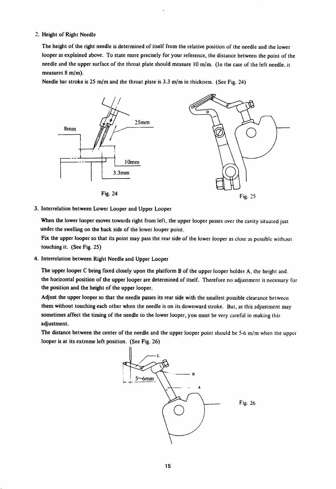
2. HeightofRight Needle
The heightofthe right needle is determined of itself from the relative position of the needle and the lower
looperasexplained
needle and the upper surfaceofthe throat plate should measure 10m/m. (In the case of the left needle, it
measures 8 m/m).
Needle
bar stroke is 25 m/m and the throat plate is 3.3 m/m in thickness. (See
8mm
1—^'
1
above.
To state more
1
10mm
3.3mm
precisely
25mm
for your
reference,
the
distance
Fig.
between
24)
the point of the
Fig. 24
3. Interrelation between Lower Looper and Upper Looper
When
the
lower
looper
moves
towards
under the
Fixthe
touching it. (See Fig. 25)
4. Interrelation between Right Needleand Upper Looper
The
the horizontal
the position and the height of the upper looper.
Adjustthe upperlooper so that the
them without touchingeachother
swelling
upper
upper
on the back sideof the lower looper point.
looper
sothat itspoint
looperCbeing
position
fixed
of the upper
closely
looper
needle
when
right
from
may
pass
the rear
upon
the
aredetermined of
passes
the
needle
left,the
platform
its rear
upper
side
Bof the
side
looper
of the
itself.
with the
passes
lower
upper
Thereforenoadjustmentisnecessary
smallest
ison itsdownward stroke. But,as thisadjustment may
sometimes affect the timingof the needle to the lowerlooper,you must be very
at^ustment.
The distance betweenthe center of the
looper isat its extreme left position. (See Fig. 26)
needle
and the upperlooper point should be 5-6 m/m
Fig. 25
over
the
cavity
situated
looperascloseaspossible
looper
holder
A,the
height
possible
clearance
carefulinmaking
when
just
without
and.
for
between
this
the upper
5~6mm
Fig. 26
15
Page 17
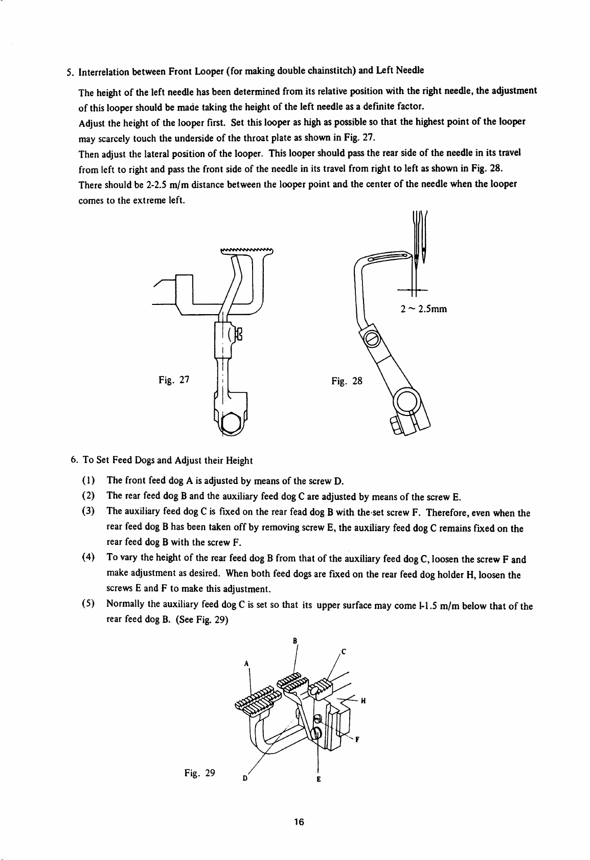
5. Interrelation
The
height
ofthis
Adjust
may
scarcely
Then
adjust
from
left to
There should be 2-2.5 m/m distance between the looper point and the centerofthe needle when the looper
comestothe
oftheleft
looper
the
height
between
touchthe
the
right
extreme
Front
needle
shouldbemade
ofthe
looper
underside
lateral
position
and
pass
the front
left.
Lx)oper
(for
making
has
been
determined
taking
the
height
first.
Set
this
of the throat plateas
ofthe
looper.
side
of the
double
chainstitch) andLeft
from
its
of the left
relative
needle
position
asa
looperashighaspossible
shown
in Fig. 27.
This
looper
should
pass
needle
inits
travel
fromright to left as
with
definite
sothatthe
the
rear
Needle
the
factor.
highest
side
2 ~
right
needle,
point
of the
needle
showninFig.
2.5mm
the
ofthe
inits
adjustment
looper
travel
28.
6. To Set Feed
(1) The front feed dog A is adjusted by means of the screwD.
(2)
(3)
(4)
(5)
Dogs
and Adjust their
The rear feed dog Band the auxiliary feed dogCare adjusted by meansof the screw E.
The
auxiliary
rear
feed
rear feed dog B with the screw F.
To
vary
make
adjustmentasdesired.
screws
Normally
rear feed dog B. (See Fig. 29)
feeddogCis fixedon the rearfeaddogBwith the set
dogBhas
the
height
E and F to make this adjustment.
the
been
ofthe
auxiliary
taken
feed
Height
offby
rear
feed
dogBfrom
When
dog
Cissetsothat its
removing
both
feed
screw
thatof the
dogs
Fig. 28
E,the
are
fixedonthe
upper
auxiliary
auxiliary
surface
screw
feed
rear
may
F. Therefore,
feed
dogCremains
dogC,loosen
feed
dog
come
1-1.5
even
when
fixed
onthe
the
screwFand
holderH,loosen
m/m
below
that of the
the
the
Fig. 29
16
Page 18
Alignment
The
comes up to
To
make
socket
the eccentric feedregulating stud witha screwdriverD.
Care
ment.
When
As
this
to
tamper
of Feed
top
surfaceofthe
this
wrench
Dogs
feed
the
latter.
adjustment,
and
then
mustbetakensothat
this
adjustment
alignment
withthis
has
setting.
has
been
andThroatplate
dogsAandBshouldbein
remove
adjust
been
the
the
inclinationofthe
there
maybeno
finished,
throughly
(See
Fig.
rear
coverAand
opening
tighten
examined
30)
feed
between
the
screwCsecurely,
and
properly
alignment
the
with
upper
coverB,loosen
thatofthe
dogssoastosatisfy
the
studEand
replace
correctedonshipment,itis
throat
the
the
above
the
feed
the
coversAand
plate
when
the
former
screwCwithahexagonal
conditionbyturning
barFafter
rather
this
adjust
B.
advisable
not
Fig. 30
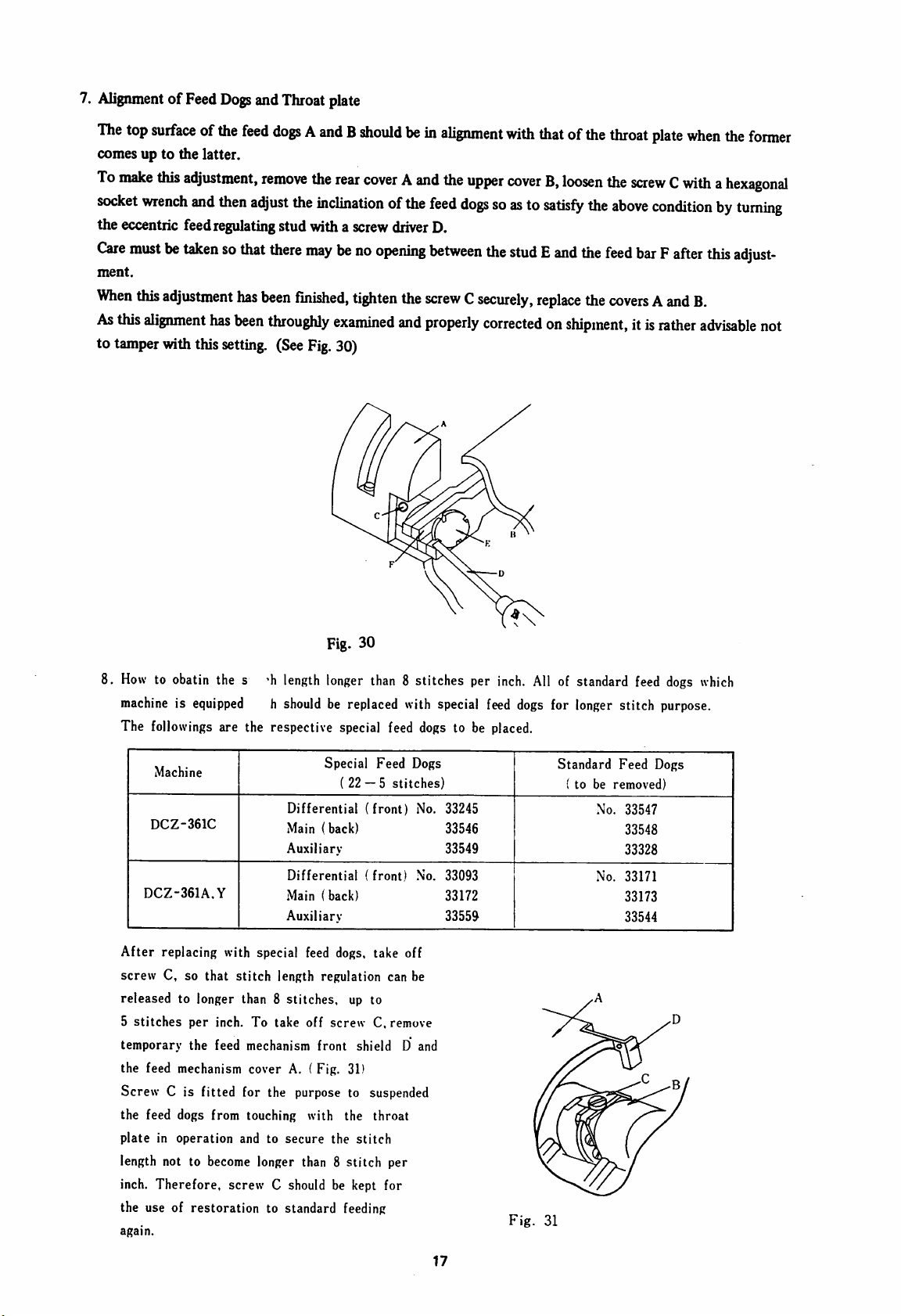
8.
Howtoobatin
machineisequipped
The followings are the respective special feed dogs to be
Machine
DCZ-361C
DCZ-361A,Y
After
replacing with special feed dogs, take off
screw C, so that stitch length regulation can be
released to longer than 8 stitches, up to
5
stitches
temporary
the feed mechanism cover A. ( Fig. 31)
Screw C is fitted for the purpose to suspended
the feed dogs from touching with the throat
plateinoperation
length not to become longer than 8 stitch per
inch. Therefore, screw C should be kept for
the use of restoration to standard feeding
again.
the s 'h
per
inch. To take off
the feed mechanism front shield D and
length
h
shouldbereplaced
Differential
Main
Auxiliary-
Differential
Main
Auxiliary
and to
secure
longer
Special
(22
(back)
(back)
screw
the
than
Feed
— 5
(front)
(front)
C, remove
stitch
8 stitches per
with
Dogs
stitches)
No.
No.
special
33245
33546
33549
33093
33172
33559
inch.
feed
placed.
dogs
Fig.
All
of standard
for
Standard
31
longer
( to be
Feed
removed)
No.
No.
feed
stitch
33547
33548
33328
33171
33173
33544
dogs
purpose.
Dogs
which
17
Page 19

9. To Sharpen Knives
In
case
the
upperorlower
Fig.32shows
Note;
By
the
precisely
promote
Tangsten
the
When
resharpening
This
prescribed10m/m
way,wecan
various
your
efficiencybythe
Carbide
knives
have
sharpening
angles
upper
length
offer
you
our
"YG-10"Sewing
kindsofsewing
maching
useofthis
alloy
withalower
ti
>
got
dull,
they
mustbesharpened.
for
upper
knives
and
Fig.33for
knives,
positionAmeasuring10m/minlength
must
notbeotherwise.
knivesata
apparatus.
knife
madeofspecial
Machine
desirable
Knife
angleina
We
recommend
steel.
lower
knives.
should
Grinder
which
jiffy.
We
can
are
youtopairanupper
alsobeground.
sharpen
sure
easily
you
knife
can
made
and
greatly
of
than
Fig. 32
holder
the
and,
accordingly,
standard
position.
the
height
Fig. 31
Further Suggestionsfor AdjustingDCZMachines
A. Skip-stitches
1. Seeif the needle, upper and lower loopersare regularly threaded.
2. See if the needle is bent. If it is bent, replace a new one.
3.
Check
if dust
gathers
gets irregular.
4. Check the interrelation among the needle, upper and lower loopers.
5. Wrongchoice of the needle often causes skip stitching.
6. As nylon thread is much stretchier than cotton thread, formation of the needle thread loop becomes
difficult. In such case, set
B. Thread Breaking
1. Check the presser foot chaining-off
burrs on these parts over which the thread passes.
inthe
needle
the
-U-
hole
of the
needle
needle a little lower
finger,
loopersand thread guidesto seeif there are some hitches and
of the
needle
2. Wrongrelation among the needle and loopers also causes thread breakage.
3. Inferior thread is the biggest causeofthread breakage.
4. Beingsusceptible to heat, nylon thread is apt to break through frictional heat in high speed operation.
In this case, apply "Yamato" SP Oil on the thread. ("Yamato" SP Oil is a lubricant developed for pre
venting skip stitches in synthetic threads.)
C.
Loose
Stitches
1.
Foreign
the
mattersentered between the tension
discs
and, accordingly, a proper tension on thread can not be obtained. Thusloose stitches often
discs
18
obstruct the
closs
contact of the frictional surface of
Page 20

D.
occur.
2.
Wrong
relation
3.
Wrong
positional
Uneven
1.
2.
3.
Stitches
Uneven
threadissentinto the looperand tightening the
When
the
stitches will be apt to occur.
When
the
cannot be fed smoothly and thus it causes uneven stitches.
stitches
work
upper
among
the
needle
and
loopers
relation
between
the
thread
mayberemediedbyadjusting
cannotbefed
edgeofthe
smoothlybysome
lower
knifeisset
causes
guides
the
tension
hitches
higher
loose
stitches.
also
causes
positionofthe
spring.
and
burrsonthe
than
the
upper
this
trouble.
looper
surfaceofthe
thread
throat
take-upsothat
plate
surface,
throat
plate,
more
uneven
the
work
4. Dull edges
5. Theuseof the threadof
E.
Undulated
1. Improper adjustmentofthe differential ratio.
2.
Improper
3.
Misalignmentofthe
4.
When
shrink.
5. Inappropriate
F.
Uncommonly
1. Blunt needlepoint. Replacea newneedle.
2.Alittle
result.
3.Institching
use
of
the knives also cause this trouble.
Seams
adjustmentofthe
the
feed
Large
smoothing
synthetic
"Yamato"
improper
surfacesofpresser
dogs
are
tilting
height
of the
Punctures
outofthe
fabrics,
SP
Oil.
pressureontension
forwards,
feed
Caused
area
the
twistoften
foot,
dogs.
bythe
around
frictional
causes
throat
seams
are
Needle
the
needle
heatofthe
uneven
spring-too
plate
strong
and
apttostretch,
Penetration
holeofthe
needle
stitches.
ortoo
feed
dogs.
and
throat
often
weak.
when
plate
causes
tilting
backwards,
often
producesagood
large
punctures.Inthis
apt
to
case,
G.
Damages
1.
2.
Note:
to the
Work
Caused
Feed
dogs
with
tips
When
the
upper
surface
cornerof the feedtips, oilstone is profitably usedto
We
have
given
But
there
may
standardmethods stated herein,depending upon kind of work,thread and other
In
such
case,
make
given herein.
too
sharp
of the
general
occur
proper
byFeed
some
Dogs
are
apttoinjure
feed
dogistilting
instructions
casesinwhich
adjustmenttosatisfy
for
the
using
you
19
work.
sidewise
level
and
adjusting
must
these
Grind
andthe
off the
make
special
off
sharp
workiscarried
feed
surface.
DCZ
Machinesinthis
adjustment
conditions,
tipsalittle
somewhat
refering
with
forward
Instructions.
different
various
to the
oil
stone.
with
either
from
conditions.
informations
the
Page 21

CAUTION
1) To
with quality high
begin
with, the oil reservoir
speed
on the oil sight gauge
machine
base
before
(Lubrication")
should
oil up to the upper red line
window
starting
at the right front of the
the
machine.
be
filled
2) Be careful replenish with oil immediately when
it has dwindled below the lower red line on the oil
sight gauge window.
a)
h)
Oil
recommended:
Sortes
Empfohlene
Calicladesdeaceite
ESSO
Shell
-
-
d'huile
Olsorten:
TERESSO
Shell
recommandees:
queserecomiendan;
47
TERAS
29
ATTENTION
(Graissage^
1) Le reservoir d' huile doit d'abord etre rempli,
avant
la mise en service de la machine,
d'une
huile
pour
marche rapide de bonne qualite jusqu'a la ligne rouge
superieure de I'indicateur de niveau d'huile au cote
avant
clroit
du
carter
de la
machine.
2) Veiller a remplir immediatement de I'huile des
que
le
niveau
I'indicateur
d'huile
de
niveau.
VORSICHT
tombe
(Schmierung)
a la
ligne
inferieure de
1) Vor Inbetriebnahme der Maschine ist zuerst der
Olbehalter bis
lases mit Schnellaufol einer guten Qualitat zu fullen.
zur
oberen
roten
Linie
des
Olschaug-
2) Es ist darauf zu achten, dass sofort 01 nachgefullt
wird wenn
Olschauglases gefallen ist.
der
Olstand bis
ATENCION
unter
die untcre Linie des
Cengrase)
1) Antes de poner en servicio la maquina se debe
llenar primeramenle el recipiente de aceite hasta la
linea roja superior del cristal de observacion que se
encuentra en el lado delantero derecho de la caja de
maquina, con aceite para alta
buena
calidad.
velocidad
de reconocida
2) Hay que cuidar que sea rellenado inmediatamente
aceite, cuando el nivel de aceite se heya bajado por
debajo do la linea inferior del cristal de observacion.
7
Oil
here
huiler
ici
bier
olen
sceitese
Oil
sight
indicateurdeniveaud'huile
Olschauglas
cristaldeobservacion.
gauge
aqui
window
drain
30®^®—
^S,Oil
Drain
Visdepurge
Olablasschraube
Tornillodesalida
Cap
Screw
 Loading...