

Page 1

Immersion Cooler
NeoCool Dip
Model BE201/201F/301
Instruction Manual
First Edition
● Thank you for choosing BE series immersion Neo
Cool Dip coolers from Yamato Scientific Co., Ltd.
● For proper equipment operation, please read this
instruction manual thoroughly before use. Always
keep equipment documentation safe and close at
hand for convenient future reference.
Warning: Read instruction manual warnings and
cautions carefully and completely before
proceeding.
Yamato Scientific America Inc.
Santa Clara,CA
Printed on recycled paper
Page 2

Page 3

Table of contents
1. SAFETY PRECAUTIONS ................................................................................................................. 1
Explanation of Safety Symbols .......................................................................................................... 1
Symbol Glossary ................................................................................................................................ 2
Warnings & Cautions.......................................................................................................................... 3
2. PRE-OPERATION PROCEDURES .................................................................................................. 4
Placement Precautions & Procedures ............................................................................................... 4
3. COMPONENT NAMES & FUNCTIONS .......................................................................................... 10
Main Unit Overview .......................................................................................................................... 10
4. OPERATION PROCEDURE ............................................................................................................ 12
Main Operation ................................................................................................................................. 12
Cooling Capacity Curves (Reference Data) ..................................................................................... 13
Choosing Coolant for Low-Temp Applications (Reference Data) ............................................................ 15
5. HANDLING PRECAUTIONS .......................................................................................................... 16
6. INSPECTION & MAINTENANCE ................................................................................................... 17
7. STORAGE & DISPOSAL ................................................................................................................ 18
Extended Storage / Unit Disposal .......................................................................................................... 18
Disposal Considerations .................................................................................................................. 18
8. TROUBLESHOOTING .................................................................................................................... 19
Troubleshooting Guide ..................................................................................................................... 19
9. SERVICE & REPAIR ....................................................................................................................... 20
10. SPECIFICATIONS ......................................................................................................................... 21
11. WIRING DIAGRAM ....................................................................................................................... 22
12. LIST OF HAZARDOUS SUBSTANCES ....................................................................................... 23
Page 4

1
1. SAFETY PRECAUTIONS
Explanation of Safety Symbols
A Word Regarding Symbols
Various symbols are provided throughout this text and on equipment to
ensure safe operation. Failure to comprehend the operational hazards and
risks associated with these symbols may lead to adverse results as explained
below. Become thoroughly familiar with all symbols and their meanings by
carefully reading the following text regarding symbols before proceeding.
Warning
Caution
Signifies a situation which may result in minor injury (Note 2)
and/or property damage (Note 3)
(Note 1) Serious injury is defined as bodily wounds, electrocution, bone
breaks/fractures or poisoning, which may cause debilitation requiring
extended hospitalization and/or outpatient treatment.
(Note 2) Minor injury is defined as bodily wounds or electrocution, which will not
require extended hospitalization or outpatient treatment.
(Note 3) Property damage is defined as damage to facilities, equipment, buildings or
other property. ( Note 1 ) Serious injury is defined as bodily wounds,
Symbol Meanings
Signifies warning or caution.
Specific explanation will follow symbol.
Signifies restriction.
Specific restrictions will follow symbol.
Signifies an action or actions which operator must undertake.
Specific instructions will follow symbol.
Signifies a situation which may result in serious
injury or death (Note 1)
Page 5

2
1. SAFETY PRECAUTIONS
Symbol Glossary
Warning
General Warning
Danger!: High
Voltage
Danger!:
Extremely Hot
Danger!: Moving
Parts
Danger!: Blast
Hazard
Caution
General Caution
Caution:
Shock Hazard!
Caution: Burn
Hazard!
Caution: Do Not
Heat Without
Water!
Caution: May
Leak Water!
Caution: Water
Only
Caution: Toxic
Chemicals
Restriction
General
Restriction
No Open Flame
Do Not
Disassemble
Do Not Touch
Action
General Action
Required
Connect Ground
Wire
Level Installation
Required
Disconnect Power
Inspect
Regularly
Page 6
3
1. SAFETY PRECAUTIONS
Warnings & Cautions
Warning
Never operate equipment near combustible gases/fumes.
Do not install or operate CF301 unit near flammable or explosive gases/fumes. Unit is NOT fire
or blast resistant. Negligent use could cause a fire/explosion. See “List of Hazardous
Substances” (P.24).
Always ground equipment.
Always ground this unit properly to avoid electric shock.
DO NOT operate equipment when abnormalities are detected.
If smoke or unusual odors begin emitting from unit, or if any other abnormalities are detected,
terminate operation immediately, turn off main power switch (Earth Leakage Breaker - “ELB”) and
disconnect power cable. Continued operation under such conditions may result in fire or electric
shock.
DO NOT operate with bundled or tangled power cable.
Operating unit with the power cable bundled or otherwise tangled, may cause power cable to
overheat and/or catch fire.
DO NOT damage power cable.
Damaging the power cable by forcibly bending, pulling or twisting may cause fire or electric
shock to the operator.
DO NOT process hazardous substances.
Never process explosive or flammable items. Fire or explosion may result. See “List of
Hazardous Substances” (P.24) for more information on these items.
DO NOT handle flammable substances without proper ventilation.
Be sure there is adequate ventilation when working with certain flammable substances (such as
ethanol, etc.), which evaporate quickly at or below room temperature, and emit flammable fumes.
Insufficient ventilation may cause a fire or explosion. See “List of Hazardous Substances” (P.24).
NEVER disassemble or modify equipment.
Attempting to dismantle or modify unit in any way, may cause malfunction, fire or electric shock.
Caution
DO NOT operate equipment during thunderstorms.
In the event of a thunderstorm, terminate operation and turn off main power switch (ELB)
immediately. A direct lightning strike may cause damage to equipment, or result in fire or electric
shock.
Page 7

4
2. PRE-OPERATION PROCEDURES
Placement Precautions & Procedures
Warning
1. Ground wire MUST be connected properly.
・ Ground wire must be connected to a proper grounding line or terminal in order to
prevent electric shock.
・ Never connect ground wire to gas lines or water pipes.
・ Never connect ground wire to telephone grounding lines or to lightning conductor rods.
Doing so may result in fire or electrical shock.
・ Never insert multiple plugs into a single outlet. Doing so may result in power cable
overheating, fire or drop in voltage.
Connect to grounded outlet
Outlet with ground receptacle
When no ground terminal is found:
●Grounding to Electrical Equipment Technical
Standards, Section 19, class D (Grounding
Resistance Max. 100Ω) is required in Japan.
Contact a local dealer, electrician, or Yamato
Sales office for location-specific electrical
requirements.
Use ground adapter for ungrounded outlets
Ground adapter
Outlet with no ground receptacle
Ground adapter
●Insert grounded plug into ground adapter.
Connect grounding wire (green) from ground
adapter to a ground terminal.
2. Place in suitable locations.
Do not place BE series unit:
・ where flammable or corrosive gases/fumes are generated.
・ where external temperature will exceed 35ºC, will fall below 5ºC or will fluctuate.
・ in excessively humid or dusty locations.
・ where there is constant vibration.
・ where power supply is erratic.
・ in direct sunlight or outdoors
Place unit in locations with sufficient space, and venilation as specified as below.
20 ㎝ or more
BE
Unit
20 ㎝ or more
Ground wire
W
3-pronged plug with
ground
w
G
3-pronged plug with
ground
20 ㎝ or more
Ungrounded outlet
115V AC only
20cm or more (rear)
Page 8

5
2. PRE-OPERATION PROCEDURES
Placement Precautions & Procedures
Warning
3. Place in locations free of flammables and explosives.
・ Never place or operate unit near flammables or explosives. BE unit is NOT fire or blast
resistant. Simply switching the main power switch (ELB) “ON” or “OFF” can produce a
spark, which could relay during operation, causing a fire or explosion when near
flammable or explosive fluids, chemicals or gases/fumes.
See “List of Hazardous Substances” (P.24).
4. DO NOT disassemble or modify.
Attempting to disassemble or modifiy this unit in any way may result in malfunction, fire or
electric shock.
Page 9

6
2. PRE-OPERATION PROCEDURES
Placement Precautions & Procedures
Warning
5. Place in dry locations.
Place unit where it will be free from liquid spray and other moisture. Failure to do so may
result in control mechanisms or internal components becoming wet, causing malfunction,
electrical shock and/or fire.
Caution
6. Place on level surfaces.
Place unit on a level and even surface. Failure to do so may result in abnormal vibrations or
noise and damage to the refrigeration system.
Page 10

7
2. PRE-OPERATION PROCEDURES
Placement Precautions & Procedures
Caution
7. DO NOT forcfully pull or excessively bend cooling coil hose.
Handle cooling coil hose with care. Pulling on or bending hose to a radius of more than
50mm may break cooling line and result in malfunction or other equipment damage.
8. Connect to a properly rated power supply.
Connect power cable to a suitable facility outlet or terminal, according to the following
electrical requirements.
Power
requirements:
BE201 (50/60Hz) Single phase 115V 2.6A/2.0A Max.3.0A
BE201F (50/60Hz) Single phase 115V 3.6A/2.0A Max.3.0A
BE301 (50/60Hz) Single phase 115V 4.7A/4.3A Max.5.5A
1. Check the line voltage on outlet or terminal to be used and properly evaluate whether to
utilize a line being shared by other equipment. If the unit is not activated by turning on the
main power switch (ELB), take an appropriate course of action, such as connecting unit to
a dedicated power source.
2. If multiple power cables are connected to a single outlet, input voltage to unit may drop,
causing degraded cooling and temperature control performance.
Never connect ground wire to gas lines, water lines or telephone grounding lines. Fire or
electric shock may result.
9 Handle power cable with care.
Never operate unit with power cable bundled or tangled; and do not modifiy, bend, forcibly
twist or pull on power cable. Doing so may cause fire and/or electrical shock.
Do not risk damage to power cable by positioning it under desks or chairs, or having it
pinched between objects. Doing so may cause fire and/or electrical shock.
Do not place power cable near kerosene/electric heaters or other heat-generating devices.
Doing so may cause power cable insulation to overheat, melt and/or catch fire, which may
Turn off main power switch (ELB) immediately and disconnect from facility terminal or outlet, if
power cable becomes partially severed or damaged in any way. Failure to do so may result in
fire or electric shock. Contact a local dealer or Yamato sales office for information about
replacing power cable if it is damaged.
Always connect power cable to appropriate facility outlet or terminal.
Page 11
8
2. PRE-OPERATION PROCEDURES
Placement Precautions & Procedures
Caution
10. Place in a safe, well-ventilated area.
In the event of an earthquake or other unforeseen incident, equipment may
unexpectedly shift or fall, causing injury. Taking preventative steps to install unit in a
safe location, away from room access doors and out of harm’s way is strongly
recommended.
Place unit so that intake and heat vents (see “Main Unit Overview” on P.11 & 12 for
location) are unobstructed and allowed to adequately draw in air and diffuse heat.
Failure to do so may cause excessive internal heat, resulting in degraded performance,
malfunction or fire. See placement guide on P.5 above.
Page 12

9
2. PRE-OPERATION PROCEDURES
Placement Precautions & Procedures
11. Select anti-freeze for container based on operating temperature.
・Choose an applicable fluid for cooling relative to objective temperature.
If objective temperature is more than 10°C, use tap water or softened tap water
If objective temperature is less than 10°C, use an antifreeze solution, such as Naiburain.
⌘ DO NOT use purified and/or deionized water as coolant.
The ready-to-use Raku-raku line of Naiburain solutions from Yamato Scientific is
recommended.
Contact a local dealer or Yamato sales office to purchase Raku-raku Naiburain solutions.
Observe the following in order to prevent malfunction and personal injury:
・ Antifreeze concentration may become decreased after extended use.
Check concentration or change entirely on a regular basis.
・ If only tap water is used, change more frequently.
・ Do not use well water, purified water or deionized water.
・ Degraded unit performance may be caused by using heavy or viscous antifreeze fluids,
such as Fluorinert (by 3M), GALDEN (by Daitoku Tech), etc.
・ Never use the following substances in BE units.
1) Corrosive chemicals
2) Solutions which become corrosive when heated, such as Fluorinert (by 3M), etc.
3) Solutions which emit harmful fumes, such as methanol
If an antiseptic agent is to be used, confirm material constitution of components with
which fluid will be in contact and whether fluid will harm these components, before
selecting.
・ Assure sufficient ventilation when ethanol or other highly flammable fluids are used as
antifreeze. Never operate unit near open flame or other ignition sources (static
electricity, etc.).
Name
Product
Code
Concentratio
n
(Wt%)
Min. STD
Temperatur
e
Container
Size
( in liters)
Raku-raku
Solution: Z16005
756071
60%
-20℃
5L
Raku-raku
Solution: Z16010
756072
10L
Raku-raku
Solution: Z10005
756073
100%
-30℃
5L
Raku-raku
Solution: Z10010
756074
10L
Raku-raku
Solution:
NFP6005
756075
60%
-10℃
5L
Raku-raku
Solution:
NFP6010
756076
10L
Page 13

10
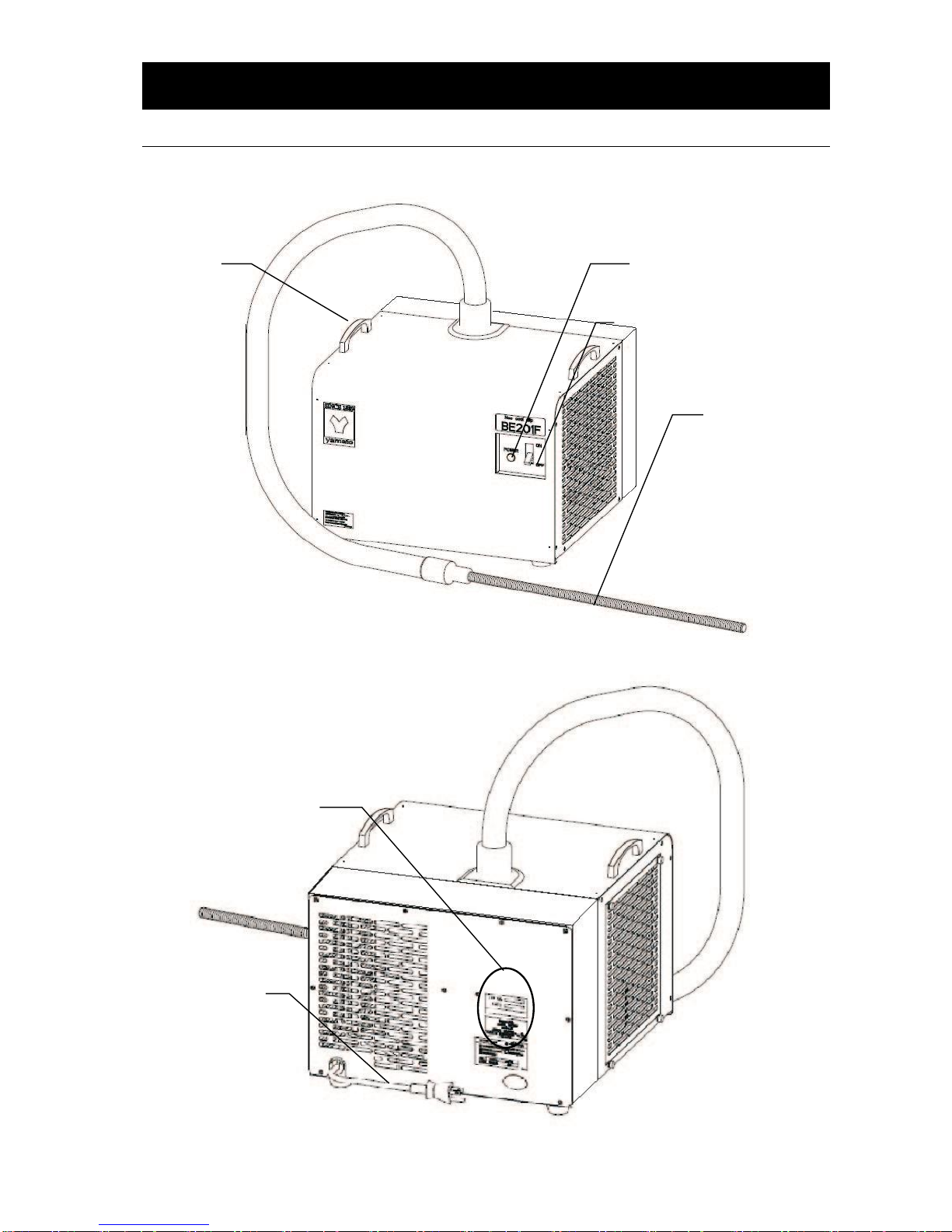
3. COMPONENT NAMES & FUNCTIONS
Main Unit Overview
BE201 front view
BE201 rear view
Power Switch (10A)
Operation
Lamp
Cooling Coil
Serial No. & Rating
Labels
Power Cable
(with plug)
Cooling Coil Sheath
Handle
Heat Vent
Side Heat Vent
Intake Grill
Page 14
11
3. COMPONENT NAMES & FUNCTIONS
Main Unit Overview
BE201F/301 front view
BE201F/301 rear view
Power Switch (10A)
Operation Lamp
Serial No. & Rating Labels
Power Cable
(with plug)
Handle
Flexible Cooling Tube
BE201F:500mm
BE301 :1000mm
Page 15
12
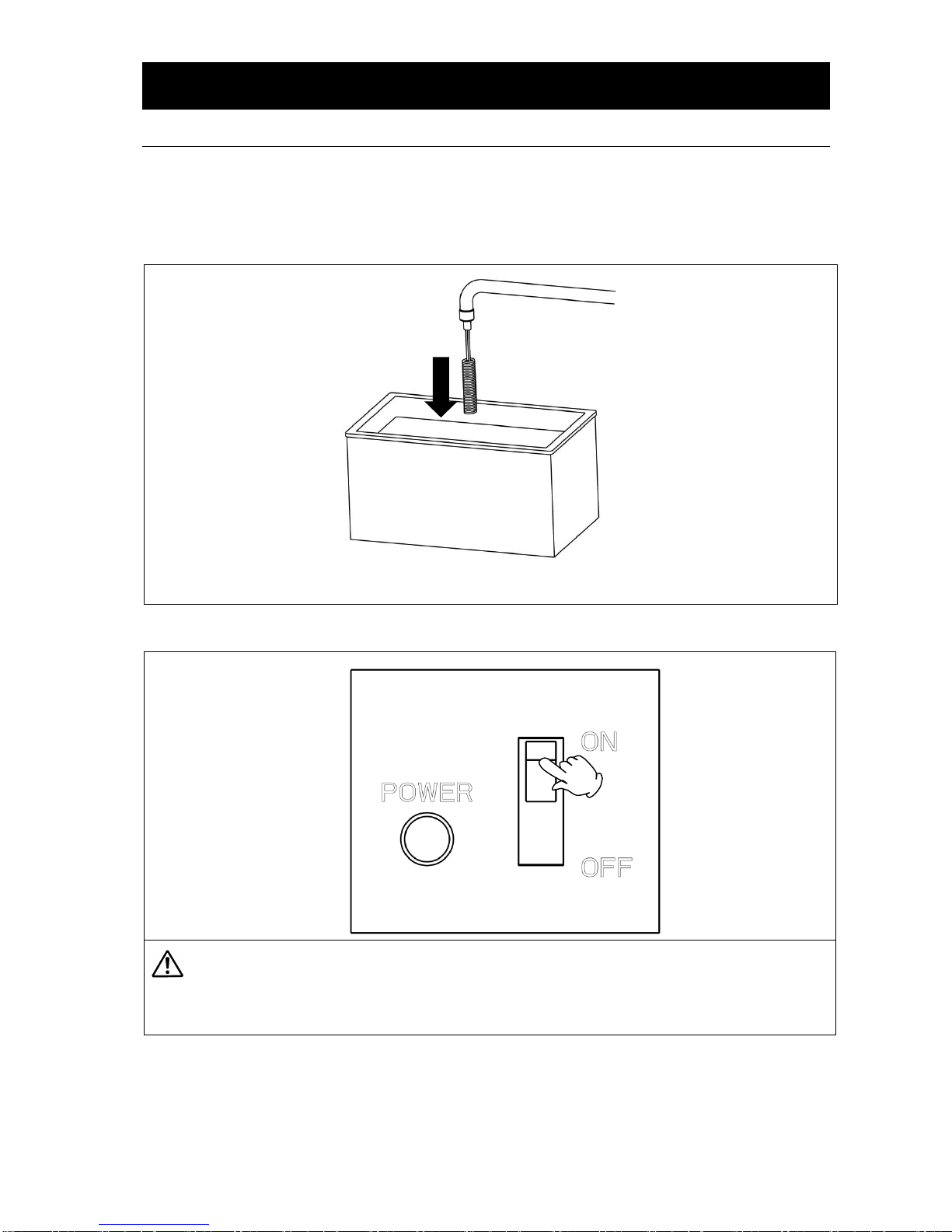
4. OPERATION PROCEDURE
Main Operation
Immerse cooling coil in fluid as shown in diagram below. Turn power switch (ELB) “ON” to start
operation.
1. Immerse cooling coil.
2. Turn power “ON”.
・ Wait at least five minutes to resume after halting an operation (e.g. turning power off). DO
NOT turn power switch “ON” and “OFF” repeatedly within a short timeframe. Damage to
the refrigeration system may result.
・ Avoid operating unit continuously at fluid temperatures abive 35°C.
Page 16

13
4. OPERATION PROCEDURE
Cooling Capacity Curves (Reference Data)
The following graphs show cooling capacities and characteristics of each BE unit by
model. Findings may vary with external temperature, fluid volume, etc. Use graph
values as reference only.
Analysis provisions
・External temperature:23°C
・Power:115V AC
・CPM:50Hz
・Antifreeze fluid: 60% Naiburain solution (covered, stirred and heat insulated)
・Fluid quantity:BE201/201F: 5 ℓ BE301: 5 ℓ /10ℓ
・Temp sensor placement:container center
BE201(5L)
BE301(10L)
BE201F(5L)
BE301(5L)
Page 17

14
4. OPERATION PROCEDURE
Cooling Capacity Curves (Reference Data)
Analysis provisions
・ Room temperature:20°C
・ Power supply: 115V AC
・ CPM:50Hz
・ Antifreeze fluid:60% Naiburain solution (covered, stirred and heat insulated)
・ Fluid quantity:BE201/201F: 5 ℓ BE301: 10ℓ
・ Temp sensor placement:container center
0
100
200
300
400
500
600
700
800
-20 -15 -10 -5 0 5 10 15 20 25 30 35 40
液温(℃)
冷凍能力
(W)
Ext. temp 20°C
BE301
BE201
BE201F
Cooling
Capacity
(W)
Fluid Temp (°C)
Page 18

15
4. OPERATION PROCEDURE
Choosing Coolant for Low-Temp Applications (Reference Data)
An anti-freeze coolant solution is required for applications below 10°C. Select a Naiburain® product
with freezing point of 10°C or more below objective temperature.
See “select coolant based on operating temperature” on P.10.
Naiburain product by type
Product Name
Characteristic
Z1、Z1-K
RH
NFP
50Wt%
100 Wt%
50Wt%
100 Wt%
50Wt%
100 Wt%
Boiling Point (in °C)
104
117
105
118
102
107
Specific Resistance
(in Ω・cm at 25°C)
625
1250
270
440
530
970
Conductivity (in S ・ m
-1
at
25°C)
0.160
0.080
0.370
0.227
0.189
0.103
Steam Pressure (KPa at
20°C)
1.7
0.5
1.7
0.5
2.3
1.3
Freezing Point (°C)
-21
Below -50
-21
Below -50
-13.5
Below -50
Specific Gravity (at 20°C)
1.05
1.10
1.07
1.134
1.026
1.048
Viscosity (mPa・s at 20°C)
2.5
9.5
2.5
9.5
2.6
9.4
Specific Heat (cal/g at 20°C)
0.850
0.670
0.850
0.670
0.773
0.642
0
-10
-20
-30
-40
-50
0
10
20
30
40
50
60
70
80
90
100
0
-10
-20
-30
-40
-50
Concentration (wt%)
Naiburain NFP
Naiburain Z, Z1-K
Naiburain® Freezing Points
(°C)
Page 19

16
5. HANDLING PRECAUTIONS
Warning
1. DO NOT process hazardous substances.
Never process explosive substances, flammable substances or substances that contain
explosives or flammables with BE units. See “List of Hazardous Substances” on P.24.
2. DO NOT operate equipment when abnormalities are detected.
If unit begins emitting smoke or abnormal odors for reasons unknown, turn off main power
(ELB) immediately, disconnect power cable from power supply, and contact a local dealer or
Yamato sales office for assistance. Continued use without addressing abnormalities may
cause fire or electric shock, resulting in serious injury or death. Never attempt to disassemble
or repair unit. Repairs should always be performed by a certified technician.
Caution
1. DO NOT climb on equipment.
Do not attempt to climb onto unit or substitute it for a proper step ladder. Units are not
designed to support bodily weight and damage may result. In addition, unit may become
unstable and tip over or fall resulting in equipment damage, serious injury or death.
2. DO NOT place objects on equipment.
Do not place any objects on unit. Doing so may cause unit to become unstable and tip over,
resulting in possible equipment damage, injury or death.
3. DO NOT operate equipment during thunderstorms.
In the event of a thunderstorm, turn off main power switch (ELB), and disconnect power cable
immediately. A direct lightning strike may cause equipment damage fire or electric shock,
resulting in serious injury or death.
4. DO NOT operate dry.
Do not operate without cooling coil immersed in fluid. Malfunction or equipment damage may
result.
5. Operate equipment as directed.
Operate BE series units only as directed in this text. Utilizing equipment for anything other
than that which it is intended may cause malfunction, damage, serious personal injury or
death. Read instruction manual thoroughly before use. Likewise, using non-Yamato
components to modify, customize or to otherwise attempt to improve unit design is not
recommended and may void warranty.
6. Keep upright.
Never tilt or place unit on its side while moving or transporting. Damage to refrigeration
system may result. If briefly tilting unit to one side or the other is unavoidable during
transport, refrain from turning power on for at least 24 hours after positioning unit upright.
Page 20

17
6. INSPECTION & MAINTENANCE
Daily general maintenance and inspection is recommended to ensure optimal performance.
Warning
● Turn off power and disconnect power cable before conducting inspection and maintenance,
unless otherwise necessary.
● Inspect and perform maintenance on unit when coolant is at room temperature.
● Do not attempt to disassemble unit.
Caution
Clean unit using a soft, damp cloth.
Never use benzene, paint thinner, scouring powder, scrubbing brush or other abrasives and
solvents to clean unit. Superficial damage and/or discoloration, as well as deformity to some
components may result.
Monthly maintenance.
Test main power switch (ELB) function.
1. Connect power cable.
2. Turn power switch ON.
3. Depress the red test switch with a fine-point object,
suchas a ballpoint pen, etc.
4. If power switch turns OFF without delay, it is
functioning normally.
Condenser fin maintenance.
・ Clogged condenser fins will degrade cooling
performance and may result in refrigeration
system malfunction. Cleaning intervals will
vary depending on usage frequency and
operating environment. Be sure to clean
condenser fins periodically.
・ Remove intake grill on left side of unit (4
screws) and clean dust from condenser fins
using a vacuum cleaner or other
suction-type cleaning device. Do not touch
fins with bare hands or fingers. Laceration
injuries may result. Do not bend or crush
fins with cleaning device.
◆ Contact local dealer or Yamato sales office for further assistance.
Test button
Page 21

18
7. STORAGE & DISPOSAL
Extended Storage / Unit Disposal
Caution
Warning
To store or to place unit out of service:
● Turn power OFF and disconnect power cable.
Disposal:
● CF301 units use a Freon alternative
refrigerant. Observe the Freon Collection Act
and request the assistance of a professional.
● Place out of reach of children.
● Dispose of as bulky or industrial waste.
Disposal Considerations
Dispose of or recycle this unit in a responsible and environmentally friendly manner.
Yamato Scientific Co., Ltd. strongly recommends disassembling unit, as far as is possible, in order to
separate parts and recycle them in contribution to preserving the global environment.
Major components and materials, comprising BE series units are listed in the table below:
Item
Composition
Main
External casing
Electrogalvanized carbon steel paneling (SFCC), baked-on
chemical-proof coating
Cooling coil
SUS304 Stainless steel
Labels
Polyethylene (PET) resin film
Caps
Synthesized rubber
Electrical
Switches and relays
Composite of resin, copper and other materials
Circuit boards
Composite of fiber glass and other materials
Power cable
Composite of synthesized rubber coating, copper, nickel and other
compounds
Refrigeration unit
Alloy of iron, copper, etc.
Internal plumbing
Hose insulation
EPM
Plumbing lines
Copper
Condenser
Iron, copper, aluminum
Cooling medium
Refrigerant
R134a(BE201/201F) R404A(BE301)
(Consult specialist for handling refrigerant.)
Page 22

19
8. TROUBLESHOOTING
Troubleshooting Guide
Troubles
Symptom
Possible Cause
Unit does not activate when
power is turned ON.
●Power cable not connected securely
●Power failure in progress
Temperature does not
decrease.
●Temperature of fluid in basin is too high or refrigeration system is
overloaded
●Cooling coil has frozen
●Condenser fins are clogged with dust
●External temperature is excessively high
●Intake vent is obstructed
●Antifreeze fluid concentration is too low
Refrigeration system does
not start.
●Refrigeration system is in overload. Turn off power switch
immediately, see possible causes for “temperature does not
decrease”, above, and turn on refrigeration system again after several
minutes.
Power failures.
In the event of a power failure, unit automatically returns to point of operation where power loss
occured and continues operating from that point when power is restored. If automatic restore
feature is not desired after power is restored, turn main power switch OFF.
◆ If problem persists, turn off power immediately, disconnect power cable and call for service.
Page 23

20
9. SERVICE & REPAIR
Requests for Repair
When a problem occurs, terminate operation immediately, turn off main power switch (ELB) and
disconnect power cable.
Contact a local dealer or Yamato sales office for assistance.
The following information is required for all repairs.
● Model name
● Serial Number
● Date (year/month/day) of purchase
● Description of problem in as much detail as possible
Guaranteed Supply Period for Repair Parts
Guaranteed maximum supply period for repair parts is 7 (seven) years from date of discontinuation for
BE series NeoCool Dip immersion coolers. “Repair parts” is defined as components which, when
installed, allow for continued unit operation.
See production/rating label on
unit. Refer to P.11 & 12 for
location.
Page 24

21
10. SPECIFICATIONS
Device
Neo Cool Dip
Model
BE201
BE201F
BE301
Operational external
temperature range
5°C~35°C
Performance
⌘ 1
Effective operating
temp.
-20°C~35°C
Cooling capacity
Approx.190W
at 0°C
Approx.190W
at 0°C
Approx.350W
at 0°C
60% Naiburain to water solution: 5L @20°C
60% Naiburain to
water solution: 10L
@20°C
Configuration
Refrigeration
system
Hitachi 160W reciprocating system
Hitachi 400W
reciprocating system
Cooling coil
Coiled tube
Flex tube
Flex tube
Φ35×170mm
SUS304
Φ15×500mm
SUS304
Φ15×1000mm
SUS304
Refrigerant,
refrigerant amount
R134a 130g
R134a 130g
R404A 170g
Safety functions
Overcurrent ELB
Standard
meausements
External
dimensions ⌘ 2
(W×D×H ㎜)
W410×D410×H303
(Excluding flex tube, cooling coil and attachment clamps.)
Power supply
(50/60Hz)
Single phase
115V 2.6A/2.0A
Max.3.0A
10A/plug included
Single phase
115V 2.6A/2.0A
Max.3.0A
10A/plug included
Single phase
115V 4.7A/4.3A
Max.5.5A
10A/plug included
Weight
Approx.26 kg
Approx.26 kg
Approx.28 kg
Included items
1 instruction manual
⌘ 1 Performance based on AC115V power supply; 20°C±5°C external temperature; 65%RH±20%
humidity; no load. Performance will vary depending on operation conditions..
⌘ 2 Protrusions excluded.
Page 25

22
11. WIRING DIAGRAM
BE201/201F/301
Symbol
Part name
Symbol
Part name
ELB1
Electric Leakage Breaker
OLR1
Over load relay
T1
Terminal block
C1
Operation capacitor
FM1
Fan motor
C2
Start capacitor
RF1
Capacitor
PTC1
PTC starting device
L1
Lamp
TF
Transformer
Page 26

23
12. LIST OF HAZARDOUS SUBSTANCES
Never process explosive substances, flammable substances or substances that contain
explosives or flammables.
Explosive
Substance
s
①Nitroglycol, Glycerine trinitrate, Cellulose Nitrate and other explosive nitrate esters
②Trinitrobenzen, Trinitrotoluene, Picric Acid and other explosive nitro compounds
③Acetyl Hydroperoxide, Methyl Ethyl Ketone Peroxide, Benzoyl Peroxide and other organic
peroxides
④Metallic Azide, including Sodium Azide, etc.
Explosive
Ssubstances
①Metal “Lithium” ②Metal “Potassium” ③Metal “Natrium” ④Yellow Phosphorus
⑤Phosphorus Sulfide ⑥Red Phosphorus⑦Phosphorus Sulfide
⑧Celluloids, Calcium Carbide (a.k.a, Carbide)⑨Lime Phosphide⑩Magnesium Powder
⑪Aluminum Powder ⑫Metal Powder other than Magnesium and Aluminum Powder
⑬Sodium Dithionous Acid (a.k.a., Hydrosulphite)
Oxidizing Substances
①Potassium Chlorate, Sodium Chlorate, Ammonium Chlorate, and other chlorates
②Potassium Perchlorate, Sodium Perchlorate, Ammonium Perchlorate, and other perchlorates
③Potassium Peroxide, Sodium Peroxide, Barium Peroxide, and other inorganic peroxides
④Potassium Nitrate, Sodium Nitrate, Ammonium Nitrate, and other nitrates
⑤Sodium Chlorite and other chlorites
⑥Calcium Hypochlorite and other hypochlorites
Flammable Substances
①Ethyl Ether, Gasoline, Acetaldehyde, Propylene Chloride, Carbon Disulfide, and other
substances with ignition point at 30 or more degrees below zero.
②n-hexane, Ethylene Oxide, Acetone, Benzene, Methyl Ethyl Ketone and other substances
with ignition point between 30 degrees below zero and less than zero.
③Methanol, Ethanol, Xylene, Pentyl n-acetate, (a.k.a.amyl n-acetate) and other substances
with ignition point between zero and less than 30 degrees.
④Kerosene, Light Oil, Terebinth Oil, Isopenthyl Alcohol(a.k.a. Isoamyl Alcohol), Acetic Acid
and other substances with ignition point between 30 degrees and less than 65 degrees.
Combustible
Gas
Hydrogen, Acetylene, Ethylene, Methane, Ethane, Propane, Butane and other gases
combustible at 15°C at one air pressure.
Excerpt from Table 1, Hazardous Substances, of Cabinet Order of the Occupational Safety and
Health Law (substances related to Articles 1, 6, and 9)
Page 27

Limited liability
Always operate equipment in strict compliance to the handling and operation procedures
set forth by this instruction manual.
Yamato Scientific Co., Ltd. assumes no responsibility for malfunction, damage, injury or
death resulting from negligent equipment use.
Never attempt to disassemble, repair or perform any procedure on BE series unit which is
not expressly mandated by this manual. Doing so may result in equipment malfunction,
serious personal injury or death.
Notice
● Instruction manual descriptions and specifications are subject to change without
notice.
● Yamato Scientific Co., Ltd. will replace flawed instruction manuals (pages missing,
pages out of order, etc.) upon request.
Instruction Manual
Immersion Cooler NeoCool Dip
BE201/201F/301
First Edition: June 6, 2017
Yamato Scientific America Inc.
925 Walsh Avenue, Santa Clara, CA 95050
Phone: 800.292.6286 / 408.235.7725
http://www.yamato-usa.com
 Loading...