

Page 1
Instruction Manual
SUPPER HIGH SPEED OVERLOCK MACHINE
SUPPER HIGH SPEED SA FE T Y S TIT CH MA CHINE
AZ7000SDR-8
AZ7000SDR-8,AZ7003SDR-8,AZ7016SDR-8
AZ7020SDR-8,AZ7025SDR-8,AZ7120SDR-8,AZ7125SDR-8
AZ7500SDR-8
AZ7500SDR-8,AZ7520SDR-8,AZ7525SDR-8
AZ7500SDR-31,AZ7520SDR-31,AZR7525SDR-31
class
class
Thank you for purchasing the AZ70 0 0SDR- 8 and AZ7500SDR- 8 class. Before using your
AZ70 0 0SDR-8 and A Z7500SD R- 8 class, please read the instr uction manual and understa nd
the c o ntents well.
Af ter reading the instr uctio n manual, please keep it in a loc atio n where it is easily accessible
to the operator.
Page 2

CONTENTS
SAFETY INSTRUCTIONS ⅰ-ⅵ
1. Name of each part 1
2. Installation 2
2.1 Semi-submerged type 2
2.1.1 Table cutting diagram 2
2.1.2 Installation 3
2.2 Fully-submerged type 4
2.2.1 Table cutting diagram 4
2.2.2 Table cutting diagram for fully-submerged type with device 6
2.2.3 Installation 7
2.3 Motor, pulley and belt 8
2.4 Hanging belt 9
2.5 Belt cover 9
2.6 Eye guard and nger guard 9
3. Sewing speed and rotating direction of pulley
4. Lubrication
4.1 Lubricating oil 11
4.2 Lubricating 11
4.3 Changing oil 12
4.4 Checking and replacing oil lter 12
5. Proper operation
5.1 Needle system 13
5.2 Installing needles 13
5.3 Adjusting thread tension 14
5.4 Pressure of presser foot 15
5.5 Releasing presser foot 15
5.6 Opening cover 16
5.7 Adjusting differential feed dog 16
5.8 Adjusting stitch length 17
10
11
13
5.9 Passing tape 18
5.10 SP device and HR device 18
5.11 Cleaning the machine 19
6. Adjustment of sewing machine 20
6.1 Needle thread tension for overlock stitch 20
6.2 Looper thread tension for overlock stitch 21
6.3 Needle thread tension for double chainstitch 22
6.4 Looper thread tension for double chainstitch 23
Page 3

CONTENTS
6.5 Width of overedge seam 24
6.6 Upper and lower knives 25
6.7 Height of feed dogs 27
6.8 Tilt of feed dog 28
6.9 Needles and loopers 29
6.9.1 Height of needle 29
6.9.2 Installing angle of lower looper 30
6.9.3 Distance between needle and lower looper 30
6.9.4 Parallel of needles 31
6.9.5 Back and forth position of lower looper 32
6.9.6 Distance between needle and upper looper 33
6.9.7 Back and forth position of upper looper 34
6.9.8 Timing relation between lower looper and upper looper 34
6.10 Needle and double chaining looper 34
6.11 Needle and needle guards for AZ7000SDR-8 35
6.11.1 Needle and needle guard(rear) 35
6.11.2 Needle and needle guard(front) 35
6.12 Needle and needle guards for AZ7500SDR-8 36
6.12.1 Needle and needle guard(rear) 36
6.12.2 Needle and needle guard(front) 36
6.12.3 Needle and needle guard for double chain stitch 37
6.13 Position of presser foot 37
7. SC10 device 38
7.1 Outline 38
7.2 Adjusting ventilating amount 38
7.3 Installation 39
8. K2 device 41
8.1
8.2 Oiling 41
Adjustment for engagement between upper trimming knife and lower trimming knife
41
9. Specifications 42
9.1 AZ7000SDR-8 class 42
9.2 AZ7500SDR-8 class 43
Attention
◇ This instruction manual is designed mainly for technicians, but it is advisable that also operators read
the instructions with mark to use the machine properly.
◇ The numbers in lower left corners of figures are figure numbers. We use them in texts as needed for
your reference.
Attention
The parts used for this product are subject to change without notice. If such a change is made, any part
of the contents and illustrations of this instruction manual may not conform to this product.
In preparing the instruction manual, we have made our best efforts for making it free of any error or
omission. If any error or omission should yet be found, it might not be rectified immediately.
Page 4
SAFETY INSTRUCTIONS
1. Safety Instruction
The sewing machine, automatic machine, and attachments (collectively called “the machine” below) involve
sewing operations that require the operator to be near moving parts of the machine. Because of this,
there is always a potential danger of unintentional contact with the moving parts. For this reason, the
operators who actually use the machine and the maintenance staff who perform maintenance and repair must
carefully read “2. Basic precautions” and “3. Precautions to be taken in various operating stage” below
and fully understand this information before operating or maintaining the machine.
The information contained in the “Safety Instruction” of this manual also includes items not found in
the product specications.
To assist in better understanding this manual and the product warning labels, warning indicators are
categorized as shown below. Be sure that you fully understand the contents and carefully follow the
instructions.
1.1 Explanation of risk levels
This indication is given when there is a danger of death or serious injury if
DANGER
WARNING
CAUTION
the person in charge or any third party mishandles the machine or does not
avoid the dangerous situation when operating or maintaining the machine.
This indication is given when there is a potential for death or serious injury
if the person in charge or any third party mishandles the machine or does not
avoid the dangerous situation when operating or maintaining the machine.
This indication is given when there is a potential danger of medium to minor
injury or damage of the sewing machine if the person in charge or any third
party mishandles the machine or does not avoid the dangerous situation when
operating or maintaining the machine.
1.2 Explanation of pictorial warning indications and warning labels
There is a risk of injury if contacting a moving section.
There is a risk of a burn if contacting a high-temperature section.
There is a risk of electrical shock if contacting a high-voltage section.
Connection of an earth cable is indicated.
The correct direction is indicated.
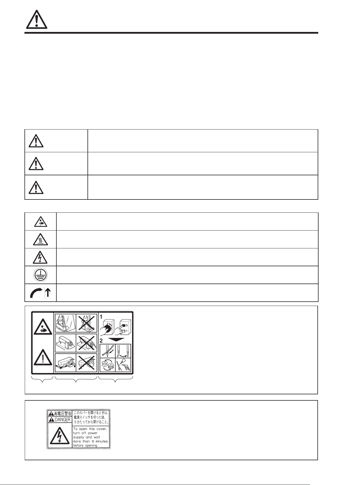
Explanation of safety label
① There is the possibility that slight to serious injury or
death may be caused.
There is the possibility that injury may be caused by
touching the moving part.
② Perform sewing work with safety cover.
Perform sewing work with safety protection device.
③ Be sure to turn the power OFF before carrying out
“threading,” “needle changing,” “bobbin changing” or
①
②
③
“oiling and cleaning.”
i
Explanation of high-voltage warning label
High voltages are owing inside the power supply of the control
box. This indicates that there is a risk of electrical shock.
When it is necessary to open the control box containing
electrical parts, be sure to turn the power off, remove the power
plug and wait for at least ve minutes before opening the cover
in order to prevent an accident resulting in electrical shock.
Page 5
1.3 Explanation of symbols
Explains the symbols used in the instruction manual.
Failure to follow the instructions can result in an injury or damage to the machine.
Be sure to follow the instructions when you operate, check, adjust or repair the machine.
Never do this.
Be sure to remove the power plug from the source of the power supply, when checking, adjusting
and/or repairing the machine or when there is the possibility that lightning may strike.
Additional explanations and notes, etc., for operation or adjustment
2. Basic precautions
SAFETY INSTRUCTINONS
1. Be sure to read this instruction manual and
all the other explanatory documents supplied
with accessories of the machine before using
the machine. Always keep the instruction manual
where it is easily accessible for the operator
and maintenance staff.
2.
The content of this section includes items which are
not contained in the specications of your product.
3. Be sure to wear safety goggles to protect
against accidents caused by needle breakage.
2.1 Applications, purpose
Our industrial sewing machines have been
developed in order to increase quality and/or
productivity in the sewing industry.
Accordingly, never use our products for other
than the intended use as described above.
2.2 Working environment
The environment in which our industrial sewing
machines are used may seriously affect their
durability, functions, performance and/or safety.
Do not use the machine in the circumstances below.
Places of high ambient temperature and/or
humidity that seriously affects sewing machines.
Outdoors, places of high temperature or in
direct sunlight.
Environments containing dust, corrosive or
ammable gases, or in contact with chemicals.
Where the voltage uctuation range is more
than ± 10% of the rated voltage.
Location where sufcient power is not available
for the power supply capacity of the controllers
and motors that is used.
Near objects where strong electric or magnetic
elds, such as high frequency welding
machines which make noise, are generated.
As dew condensation may occur when suddenly
bringing the machine from a cold environment
to a warm place, in order to prevent accidents
caused by breakage or malfunction of the
electrical components, be sure to turn the power
on after waiting for a sufcient period of time
until there is no sign of water droplets.
When lightning occurs, be sure to stop operation
and remove the power plug in order to prevent
accidents caused by breakage or malfunction of
the electrical components.
2.3 Safety devices and warning labels
Be sure to operate the machine after verifying
that safety device(s) are correctly installed
in order to prevent accidents caused by lack
of the device(s).
With regard to safety device(s), please refer
to page vi.
If any of the safety devices is removed, be
sure to replace it and verify that it works
normally in order to prevent accidents.
Be sure to keep the safety label and/
or warning lables attached to the machine
clearly visible in order to prevent
accidents. If any of the labels has become
stained or come unstuck, be sure to replace
it with a new one.
2.4 Instruction and training
○ Operators and workers, who supervise, repair or
maintain the machine head and/or machine unit,
are required to have the adequate knowledge and
operation skills to do the job safely.
○ The manager should plan and enforce the safety
education and training of those operators and
workers beforehand.
2.5 Modication
Never modify and/or alter the machine in
order to prevent accident that can result in
personal injury or death. Yamato assumes no
responsibility for damages or personal injury
or death resulting from a machine which has
been modied or altered.
ii
Page 6
iii
SAFETY INSTRUCTINONS
WARNING
2.6 Items for which the power to the machine
has to be turned off
Be sure to immediately turn the power off if
any abnormality or failure is found or in the
case of power failure in order to protect
against accidents that can result in personal
injury or death.
To protect against accidents resulting from
abrupt starting of the machine, be sure to
carry out the following operations after
turning the power off.
● When threading to the parts such as the
needle, looper, spreader, etc., or when
changing the bobbin.
● When changing or adjusting all component
parts of the machine.
● Adjusting the stitch length
● Adjusting the differential feed ratio
● When inspecting, repairing or cleaning the
machine or leaving the machine.
○ Be sure to remove the power plug by holding
the plug section instead of the cord section
in order to prevent electrical shock, earth-
leakage or re accidents.
○ If the machine is using a clutch motor, to
protect against accidents resulting from abrupt
starting of the machine, be sure to carry out
the above operations after verifying that the
machine has stopped completely, since the
motor continues turning for a while even after
turning off the power supply switch.
3 PRECAUTIONS TO BE TAKEN IN VARIOUS
OPERATING STAGES
3.1 Unpacking
Be sure to unpack the machine from the top.
If the machine is packed in a wooden crate, be
careful of the nails. Remove the nails from
the board.
Never hold the parts near the needle or
threading parts when removing the sewing
machine head from the buffer of the box.
Removing and carrying the sewing machine head
should always be carried out by two or more people.
Take out the machine very carefully while
checking the position of the center of gravity.
Preserve the cardboard box and packing material
carefully in case secondary transport is
needed in the future.
Disposal of the machine waste
The proper disposal of the machine waste is the
responsibility of the customer, and must be
disposed of in accordance with the locally valid
environmental protection regulations.
The materials used in the machines are steel,
aluminum, brass and various plastics.
A specialist should be commissioned if necessary.
3.2 Transportation
Be sure to take sufcient safety measures to
prevent falling or dropping when lifting or
moving the machine.
If the machine and/or your hands are stained
with oil, the machine may easily fall to the
oor. Therefore, wipe off the oil carefully.
To prevent accidents during transportation,
repackage in the same state as the original
delivery packaging.
Be particularly sure to fully wipe off
any oil adhering to the machine before
repackaging.
The machine head should be carried by two or
more people.
The machine should be carried by people
only when moving to the table or transfer
hand truck, and all other transportation
operations should use a hand truck. When
moving to the table or hand truck, be
careful that the machine is not subjected to
excessive impact or vibrations. Otherwise the
sewing head could fall over.
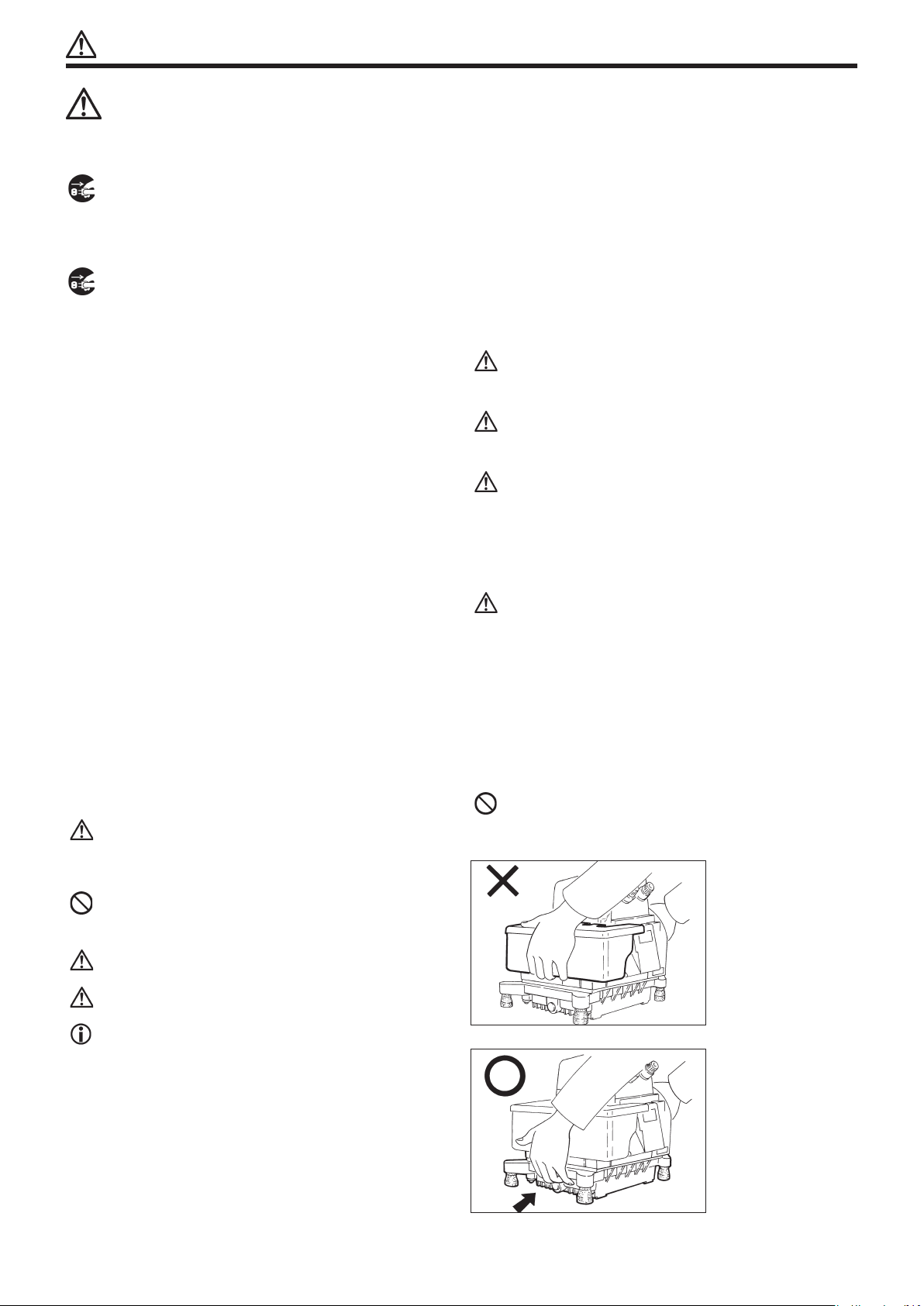
When handling the machine, do not carry the
bottom part of the cloth plate cover.
Disposal of the packaging
The packaging material of the machine consists
of wood, paper, cardboard and polystyrene foam.
The proper disposal of the packaging is the
responsibility of the customer, and must be
properly disposed of in accordance with the locally
valid environmental protection regulations.
Page 7
iv
SAFETY INSTRUCTINONS
3.3 Installation, preparation
3.3.1 Machine table
Prepare a machine table (table board and legs)
that has sufcient strength to withstand the
weight of the sewing head and any reaction
while operating.
Securely join the table and legs to ensure
sufcient strength to withstand the weight
of the sewing head and any reaction while
operating.
○ Maintain a comfortable working environment
with consideration of the lighting and the
arrangement of sewing machine to enable the
operators to work smoothly.
○ Adjust the height of the table according to
the posture of the worker.
Also, when installing the control box and the
related parts on the sewing machine, make
sure not to affect the posture of the worker.
If casters are tted to the table stand, be
sure to use high-strength casters with a
locking mechanism.
Lock the casters except when moving the machine.
3.3.3 Handling machine oil
Keep machine oil out of the reach of children.
Be sure to ll or add lubrication oil to
sewing machines before operating them.
Use “Yamato SF oil 28” as specied.
If machine oil gets in your eyes, it may
cause eye inammation. Always wear protective
glasses to prevent the oil from getting in
your eyes.
*Should machine oil get in your eyes, wash
them with fresh water for 15 minutes and
then consult a medical doctor.
If oil adheres to your eyes or body, be sure
to immediately wash it off in order to prevent
inammation or irritation.
If oil is swallowed unintentionally, be sure to
consult a medical doctor in order to prevent
diarrhea or vomiting.
Methods of disposing of waste oil and/or
containers are specied by law. Dispose of
it properly as required by law. If you have
further questions on its disposal, consult
the place of purchase.
3.3.2 Wiring and grounding
Never connect the plug for power supply until
assembly is nished.
Also, be sure to avoid the usage of multipleoutlet extension cords in order to prevent
electrical shock, earth-leakage or re
accident.
Fix the connectors securely to the sewing
machine head, motor, and electric apparatus.
Also, when unplugging the connectors, hold
the connector part.
When wiring the connection cords, please take
care of the following.
○ Connect the cords away from the driving
parts.
○ Do not apply excessive force to the
connection cords.
○ Do not bend the cords excessively.
Never use staples to fasten the cables. Otherwise
it may cause a short circuit and/or re.
Arrange the ground wire securely to the designated
position on the machine head.
Also, wire separately from the grounding for
other equipment.
After opening the oil container, be sure
to seal it to prevent dust and water from
getting into the oil and keep it in the dark
to avoid direct sunlight.
Do not store in high-temperature areas or
areas exposed to an open ame.
WARNING
3.4 Before operation
○ Never put your hand under the needle or near
the moving parts of the machine when turning
on the power supply switch.
○ When operating a new sewing machine, make
sure the rotating direction of the pulley
agrees with the rotating-direction mark.
○ Before turning the power on, visually check
the cables and connectors for conditions such
as damage, disconnection and/or loosening.
○ If a table stand with casters is used, be
sure to secure the table stand by locking the
casters or securing the legs with adjusters,
if provided, in order to prevent accidents
caused by abrupt moving of the machine.
Page 8

v
SAFETY INSTRUCTINONS
WARNING
3.5 During operation
○ Be sure to operate the sewing machine using
the safeguards such as belt cover, nger
guard, and eye guard.
○ Never place your nger, hair or objects under
the needle or close to the moving parts while
operating the sewing machine.
○ Be sure to turn off the power supply switch
when threading or replacing the needles.
○ Never place your hands close to the knives
(upper and lower knives) when operating the
sewing machine with the trimming devices.
○ Be sure to turn off the power supply switch
when terminating the sewing work or leaving
the sewing machine.
○ In the event of the power failure, be sure to
turn off the power.
Also, if the sewing machine malfunctions,
makes abnormal sound or emits unusual odors
while operating, be sure to turn off the
power supply switch.
○ While operating the machine, wear clothing
that cannot be caught in the machine.
○ Do not put any tools or other unnecessary
objects on the machine table while running
the machine.
○ If a clutch motor type is used, it will
continue running for a while even after the
power is turned off. Therefore, be careful
because the machine could start running by
pressing the machine pedal.
○ If a servomotor is used, the motor does not
produce noise while the machine is at rest.
Be sure not to forget to turn the power off
in order to prevent accidents caused by
abrupt starting of the machine or motor.
○ To prevent entanglement accidents in machines
with a puller mechanism, keep your hands,
hair, and clothing away from the machine.
WARNING
3.6 Maintenance, inspection and repair
○ Maintenance, inspection, and repair must be
performed by staff that have received special
training and fully understand and follow the
information in the instruction manual.
○ Be sure to turn off the power supply switch
and make sure the sewing machine and motor
completely stop before the maintenance,
inspection, and repair. (If the machine is
using a clutch motor, take care that the
motor keeps turning for a while even after
turning off the power supply switch.)
○ Do not attempt to modify the machine at your
own discretion. We are not responsible for
accidents caused by such modication.
○ Use genuine Yamato parts when repairing the
machine and/or replacing the parts. We are
not responsible for accidents caused by any
improper repair/adjustment and substituting
other parts for those manufactured by Yamato.
○ Turn off the power supply switch if removing
or replacing any parts or during adjustment
of the sewing machine.
○ Be sure to also remove the gasket if the
cover is removed for maintenance, inspection,
and repair. If the gasket is not removed, the
edge of gasket may cause injury.
○ Do not pull the cord when removing the plug.
Be sure to hold the plug itself.
○ A high voltage is applied inside the control
box. Turn off the power supply switch and
wait for at least ve minutes before opening
the cover.
○ Be sure to replace the safety devices and/
or safety covers if removed for maintenance,
inspection and repair.
○ After performing maintenance, inspection and
repair, make sure that turning on the power
does not pose any danger to you.
When operating the machine for the rst time
after work is performed, run at low speed to
check for abnormal sounds or other problems
before performing high-speed operation.
4. Recommended check points for maintaining
machine performance
(1) Perform regular cleaning of the machine parts
by following the instruction manual.
(2) Perform regular inspection of the lubrication
oil by following the instruction manual, and
rell or replace the oil as required.
(3) Because the oil-proof parts use rubber, their
oil-proof performance is reduced over time.
○ If the seals or other stationary parts
fall off or begin to lose their sealing
performance, replace them with new parts.
○ The replacement period for parts used in
the movable sections varies depending
on the machine operating conditions,
environment, maintenance, and oil used,
but replacement every several years is
recommended.
(4) For details about the replacement procedure,
please contact your local dealer or Yamato.
Page 9
vi
SAFETY INSTRUCTINONS
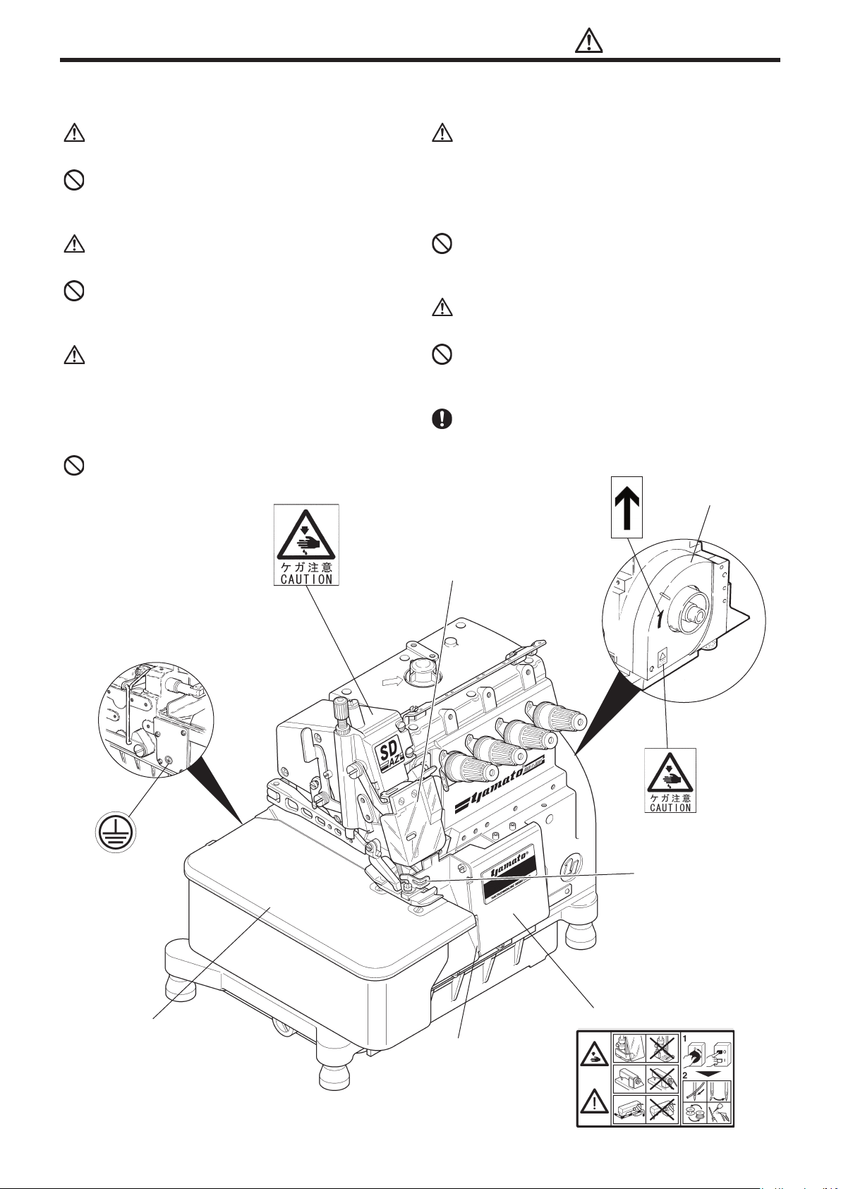
5. Safety devices and warning label affixing locations
Belt cover
The belt cover prevents entanglement with the
belt.
Do not operate with the cover removed.
Front cover
The front cover prevents contact with the
moving parts inside the cover.
Do not operate with the cover opened.
Eye guard
The eye guard prevents injury to the operator’
s eyes due to breaking of needles during the
sewing operation. This section also houses
the needle thread take-up, upper knife, and
other moving parts.
Do not operate with the eye guard opened.
Finger guard
The nger guard prevents the operator’s ngers
from going under the needle. However, there
is some space at the top of the nger guard
and other sections, and so there is a risk of
nger insertion.
Do not operate when the nger guard is removed.
Cloth plate
The cloth plate prevents contact with the
moving parts inside the cloth plate.
Do not operate when the cloth plate is opened.
Safety label, warning label
Reafx the labels if they start peeling off or
become dirty and illegible.
Belt cover
Eye guard
Finger guard
Cloth plate
Safety label
Front cover
Page 10

DECLARATION OF INCORPORATION OF PARTLY COMPLETED MACHINERY
We hereby declare that the sewing machine(sewing head) described below;
1. Must not be put into service until the machinery to which it is incorporated has been
declared inconformity with the provisions of the Directive 2006/42/EC, and
2. Conforms to essential requirements of the Directive 2006/42/EC, described in the
technical documentation, and
3. To be prepared with the above technical documentation compiled in accordance with part
B of Annex VII, and
4. Relevant information on wish should be transmitted in response to a reasoned request by
the national authorities by the electronic method or other according to the request.
Model : AZ7000SDR-8 and AZ7500SDR-8 class
Serial No. :
Description : Industrial sewing machine
Function : Make stitches and sew
Applied harmonized standards in particular :
EN ISO12100-1, EN ISO 12100-2, EN ISO10821, EN 60204-31
Manufacturer :
YAMATO SEWING MACHINE MFG. CO., LTD.
2-10-3 Hotarugaike Minami-machi Toyonaka
Osaka Japan
Page 11
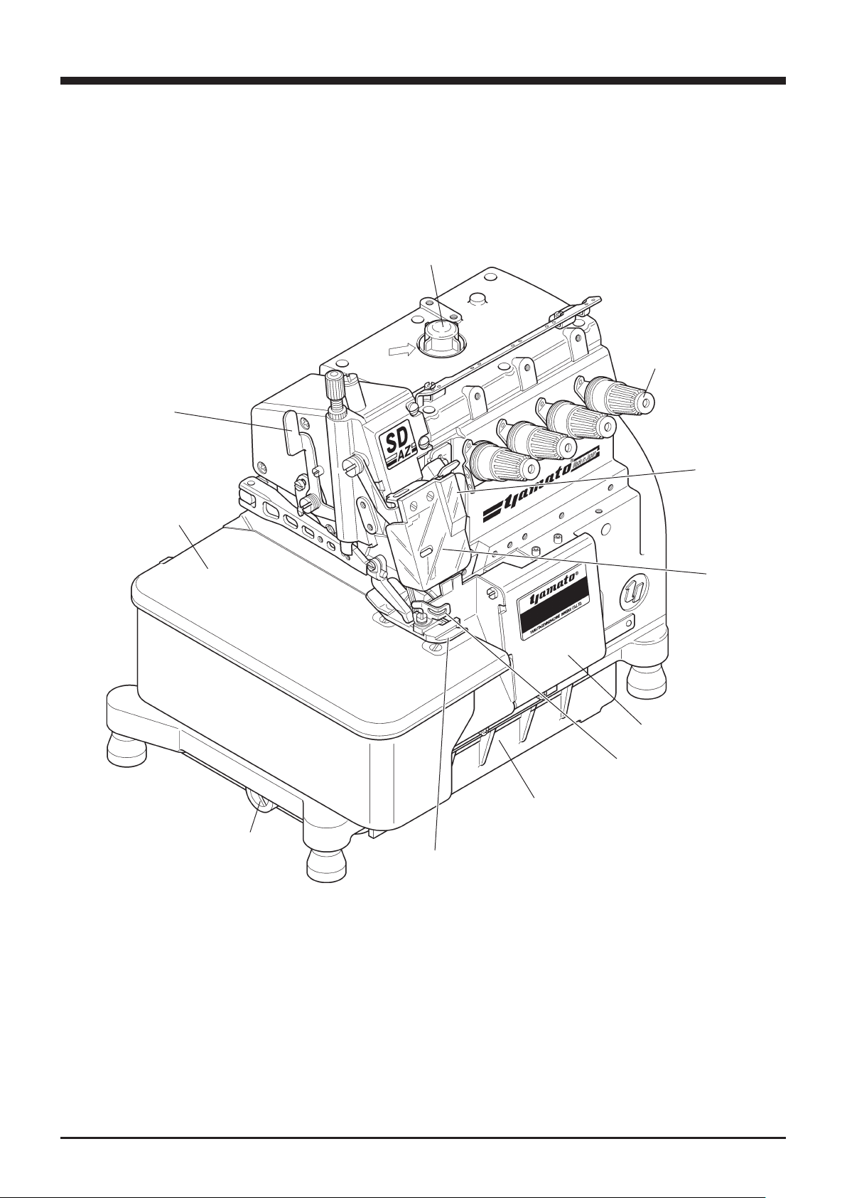
1. Name of each part
Presser foot
release lever
Oil cap
Thread tension
spring cap
SP device
(behind Eyeguard)
Fig. 1-1
Cloth plate
Eye guard
Front cover
Finger guard
Oil reservoir
Drain hole screw
Presser foot
AZ7000SDR -8, 75 00 SDR- 8
1
Page 12
2
AZ7000SDR -8, 75 00 SDR- 8
2. Installation
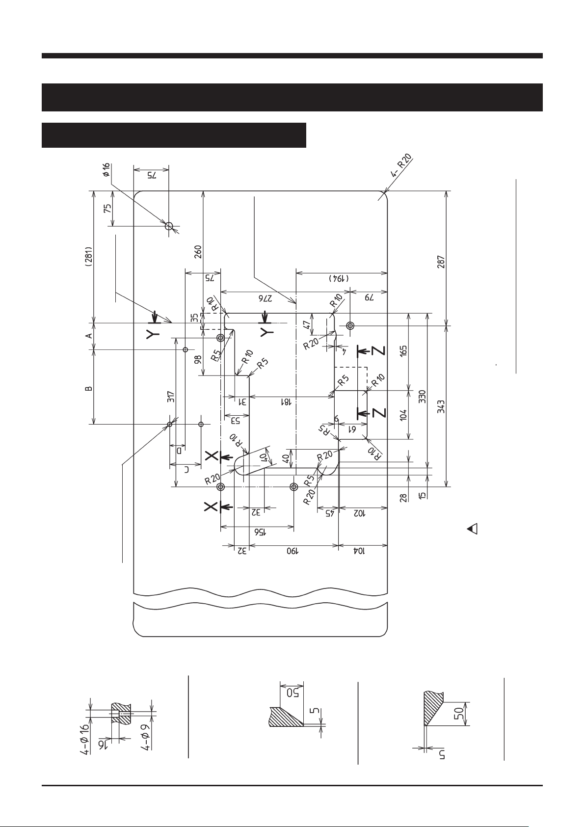
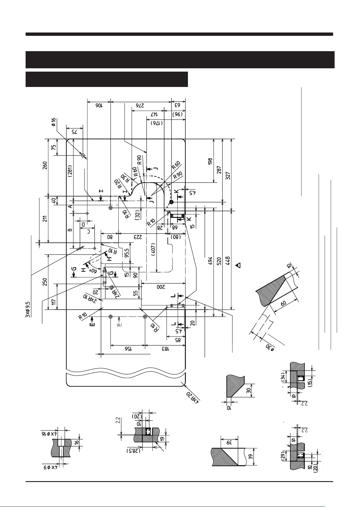
2.1 Semi-submerged type
2.1.1 Table cutting diagram
Center of
machine pulley
Center of
crank shaft
Table dimensions 1200×540×40 mm
operator
3-Φ9.5
installing hole for motor
Fig. 2-1
Section X - X
Refer to the instruction man-
ual of the motor for dimen-
sions A, B, C, and D.
Section Y - Y
Section Z - Z
Page 13
3
AZ7000SDR -8, 75 00 SDR- 8
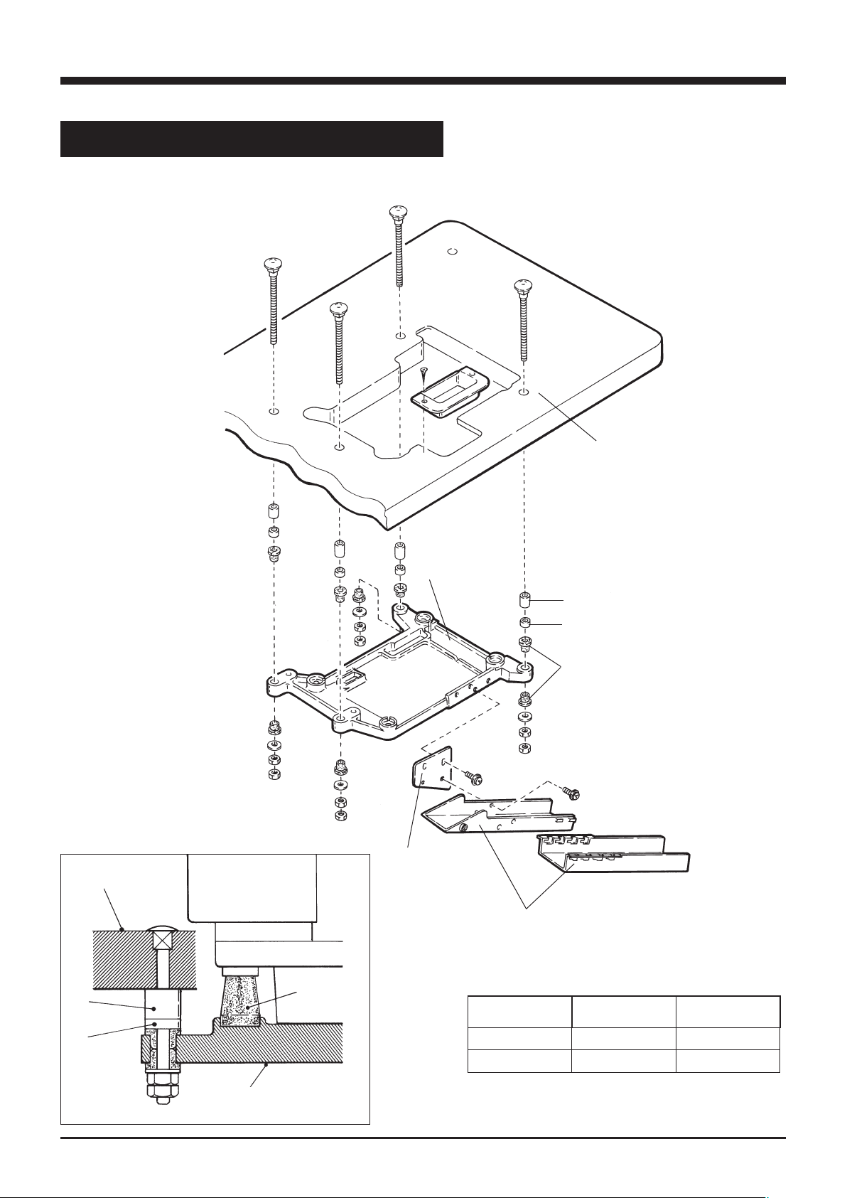
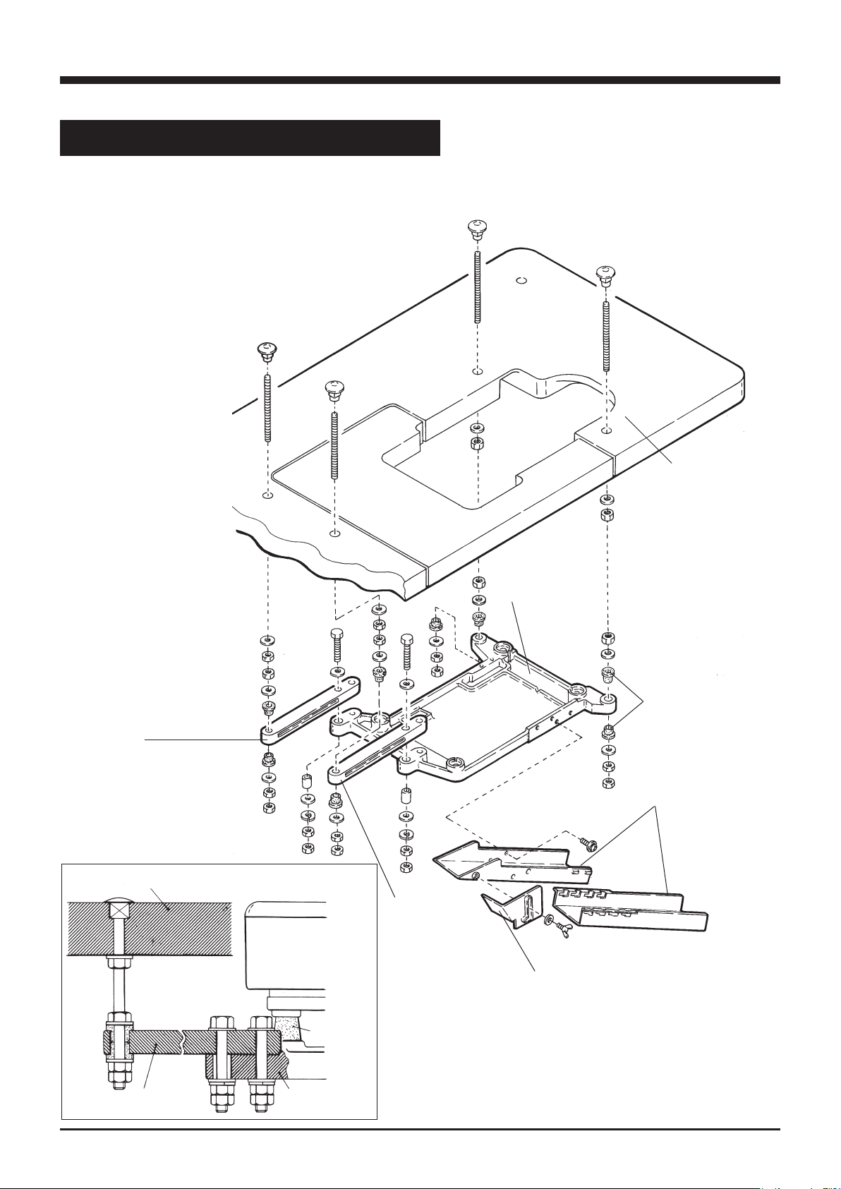
2.1.2 Installation
Install the machine correctly referring to Fig. 2-2 and 2-3.
machine table
③
2. Installation
①
②
③
Fig. 2-2
rubber
cushion
supporting
④
board
⑥
chute (upper)
support
①
②
supporting board
⑤
rubber cushion
chute
⑦
Table 1 The number of spacers ① and ②
thickness of
table
40㎜ 4 4
45㎜ 4 not necessary
pcs. of ① pcs. of ②
④
Size of spacers : ①=15㎜ ②=5㎜
Fig. 2-3
Page 14
2. Installation
4
AZ7000SDR-8, 7500SDR-8
2.2 Fully-submerged type
2.2.1 Table cutting diagram
center of
main shaft
center of
machine pulley
Table dimensions 1200×540×40 mm
0.5(clea rance)
Refer to the instruction man-
ual of the motor for dimen-
0.5(clearance)
sions A, B, C, and D.
operator
magnet
(installing hole for motor)
Section H-H
magnet
installation position of magnetic catch.
made by SUGATSUNE KOGYO Co. Ltd.
Section J - J
drilling
table
auxiliary
0.5 (clearance)
0.5(clea rance)
auxiliary table
Note) Indication of magnet and magnet catch plate can be referred to
K - K
Ref.) Magnetic catch JM-63G-15 and magnetic catch plate AS-68
K’- K’
Section
Fig. 2-4
Section E - E
G - G
G’- G’
table
auxiliary
I - I
Section
table
auxiliary
I’- I’
Section
L - L
L’- L’
Section
Page 15
2. Installation
5
AZ7000SDR-8, 7500SDR-8
注)マグネット、受座の表示は、マグネットキャッチを組付ける参考位置である。
参考)マグネットキャッチスガツネ工業(株)製 JM-63G-15 及び受座AS-68等
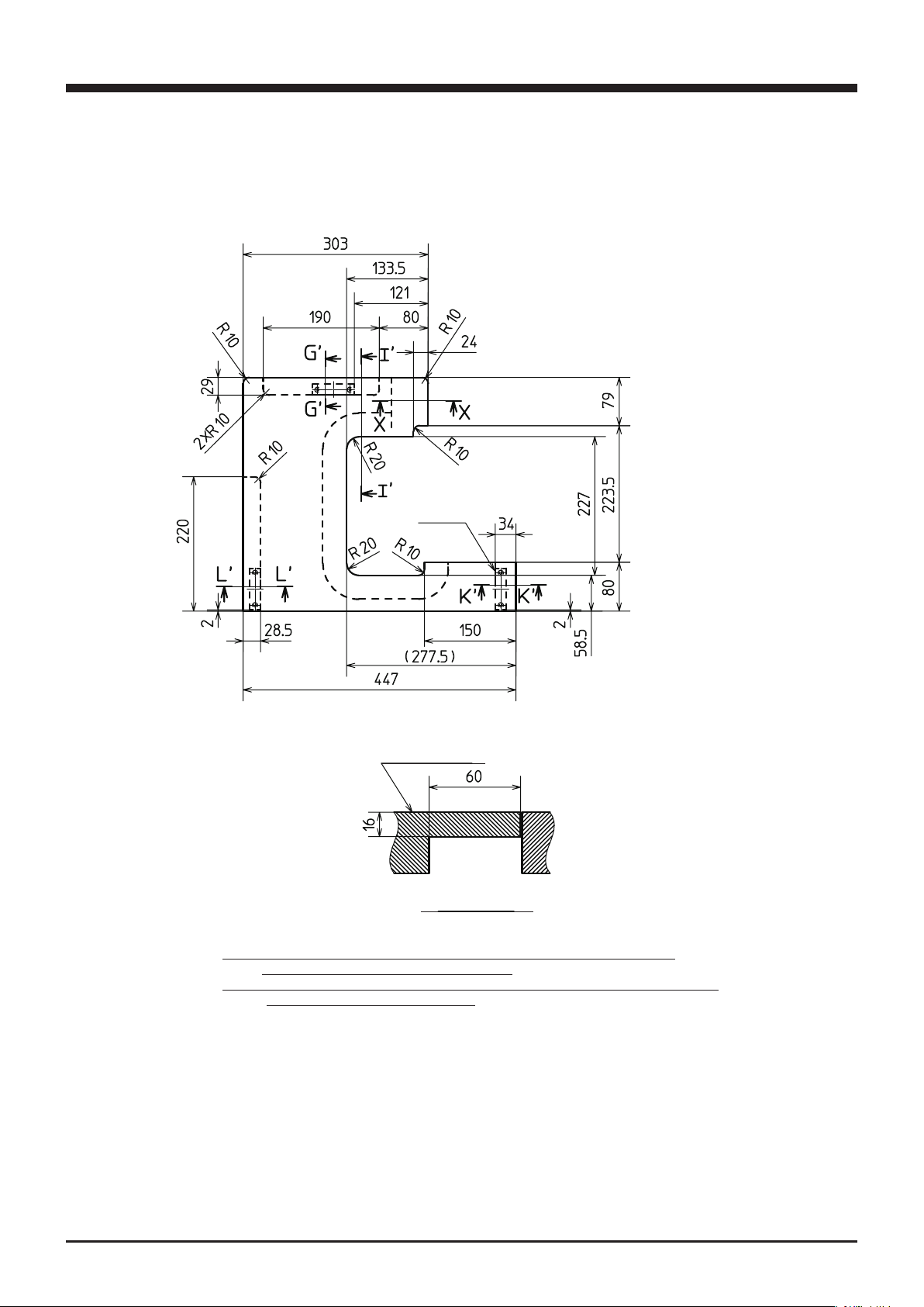
Cutting diagram of auxiliary table
3×magnet
catch
Fig. 2-5
auxiliary table
Section X - X
Note) Indication of magnet and magnet catch plate can be referred to
installation position of magnetic catch.
Ref. ) Magnetic catch JM-63G-15 and magnetic catch plate AS-68 made by
SUGATSUNE KOGYO Co. Ltd.
Page 16
2. Installation
6
AZ7000SDR-8, 7500SDR-8
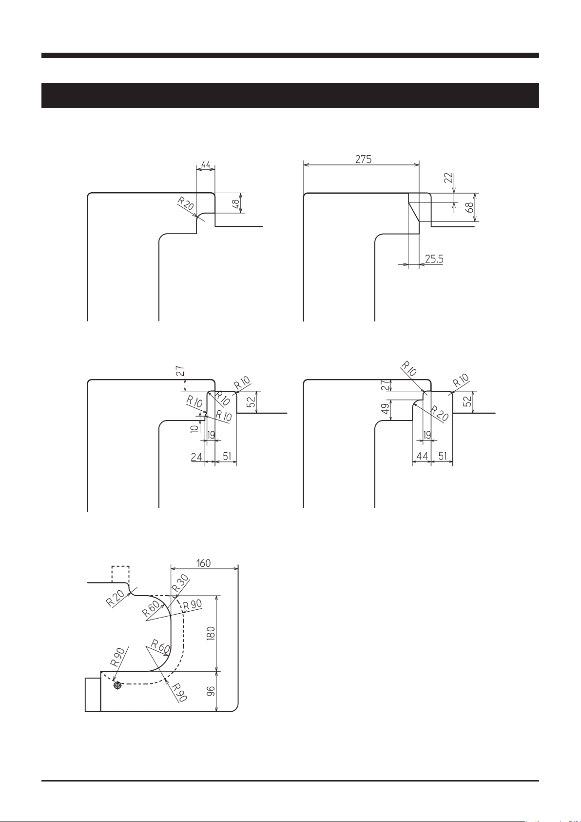
2.2.2 Table cutting diagram for fully-submerged type with device
To set up a machine with device, install the device with below dimensions and refer to “2.2.1 Table cutting
diagram” (Fig. 2-4, 2-5).
AZ7000SDR-8, AZ7500SDR-8 classes
with MT22 device
AZ7000SDR-8 class with K2 deviceAZ7500SDR-8 class with K1 device
AZ7000SDR-8, AZ7500SDR-8 classes
with MU44, 45 device
Using servomotor
Fig. 2-6
Page 17
2. Installation
7
AZ7000SDR-8, 7500SDR-8
2.2.3 Installation
Install the machine correctly by referring to Fig. 2-7 and
2-8.
Adjust the position of supporting board so that the machine can be set horizontally and the cloth plate can be
set on the same height or a little higher than the machine
table.
machine table
①
③
supporting
board connector
Fig. 2-7
①
rubber
cushion
③
supporting
board connector
supporting
②
board
⑤
supplementary
chute cover
supporting board
④
rubber cushion
chute
⑥
③
②
Fig. 2-8
Page 18

2. Installation
8
AZ7000SDR-8, 7500SDR-8
ГБХФЙПО
2.3 Motor, pulley and belt
See the instruction manual for the motor to use and install
the motor properly.
To install the clutch motor, align the center of the machine
pulley with that of the motor pulley when the motor pulley
shifts to the left by toeing down the pedal.
V-belt of M-type
Fig. 2-9
NOTE: Table 2 shows the outside diameter of the motor
pulley, sewing speed of the machine, and size of
the belt when using the clutch motor of 3-phase,
2-pole, 400W(1/2HP).
The outside diameter on the table shows the
nearest size to the calculated values based on the
commercial pulleys at intervals of 5 mm.
Use only those motor pulleys applicable to the machine.
If not, the sewing speed will be over maximum and it can
cause the machine to damage.
Servomotor:
Calculate the outside diameter of a motor pulley from the
formula as below.
Or see Table 3 to select a proper motor pulley diameter.
outside
diametor
of pulley
(㎜)
90 6000 M34 M29
95 6400 M34 M30
100 6700 M35 M30
105 5900 7000 M35 M30
110 6200 7200 M35 M31
115 6500 7500 M36 M31
120 6700 M36 M32
125 6850 M37 M32
130 7000 M37 M32
135 7300 M37 M33
140 7500 M38 M33
sewing speed
of machine
(sti/min)
50 Hz 60 Hz
size of belt
semi-
submerged
Table 2
outside diameter of motor pulley
sewing speed
of machine
(sti/min)
speed of servomotor
3000 rpm 3600 rpm
(㎜)
full-
submerged
Outside diameter Usual sewing speed
of motor pulley Servomotor speed
= ×48.5 + 5 mm
Belt
Use a V-belt of M type.
For belt size, refer to Table 2.
6000 102 86
6200 105 89
6500 110 99
6700 113 95
7000 118 99
7200 121 102
7500 126 106
Table 3
Page 19

2. Installation
9
AZ7000SDR-8, 7500SDR-8
2.4 Hanging belt
ГБХФЙПО
ГБХФЙПО
②
Be sure to install belt cover to prevent you from injuring
and a material from being caught by the belt.
Use the V-belt of M-type.
(1) Hang the belt ① on the machine pulley ②, and then
on the motor pulley ③ while rotating the machine pul-
ley.
(2) Adjust the belt tension so that the belt has 10 to 20
mm slack when its center is pressed with 10 N .
(3) Lock the motor with the adjusting bar ④.
2.5 Belt cover
To prevent you from getting injured and a material from
being caught by the belt, be sure to install the belt cover.
①
10 - 20㎜
③
④
Fig. 2-10
⑤
(1) Install the auxiliary belt cover ⑤ as shown in the g-
ure.
(2) Install the belt cover ⑥ as shown in the gure.
Fig. 2-11
⑥
2.6 Eye guard and finger guard
To ensure safe use, ALWAYS install the eye guard ⑦ and the nger guard ⑧ on the prescribed position during operation.
⑧
⑦
Fig. 2-12 Fig. 2-13
Page 20

10
AZ7000SDR -8, 75 00 SDR- 8
3.
ГБХФЙПО
Table 4 shows the maximum sewing speed of each model.
Run a new machine at 15 to 20% lower sewing speed of
its maximum sewing speed during the rst 200 hours (for
about one month) so that the machine can offer a long
service life in good condition.
The rotating direction of the motor pulley ① and the machine pulley ② is clockwise as shown in the gure.
Sewing speed and rotating direction of pulley
②
①
If rotating in reverse direction, oil can not be supplied
properly. It can cause the machine to damage.
Fig. 3-1
m o d e l
AZ7000SDR-8 class
AZ7120SDR-8 class
AZ7500SDR-8 class
AZ7500SDR-31,AZ7520SDR-31 class
Table 4
max sewing
speed(sti/m in)
7500
7000
7500
7000
Page 21

11
AZ7000SDR -8, 75 00 SDR- 8
4. Lubrication
ГБХФЙПО
ГБХФЙПО
4.1 Lubricating oil
Use YAMATO SF OIL No. 28.
NEVER add additives to the oil.
If added, it can cause the deterioration of the oil and the
damage to the machine.
4.2 Lubricating
When using a new machine or a machine which has not
been run for a while, supply few drops of oil to the needle
bar ① and the looper bar ②.
①
Remove the oil cap ③ indicated “OIL-IN” and supply oil
to the upper line of the oil sight gauge ④.
Make sure that the oil splashes from the nozzle inside the
oil cap ③ when running the machine.
If oil does not splash from the nozzle, see “4.4 Checking
and replacing oil lter” on page 12.
Too much oil or insufficient oil can cause oil leakage and
machine trouble. Be sure to keep the oil level between
the lines. Also too much lubrication can cause the oil to
scatter and material to be stained.
④
Fig. 4-1
②
Fig. 4-2
③
Fig. 4-3
Fig. 4-4
Page 22

12
AZ7000SDR -8, 75 00 SDR- 8
4. Lubrication
БФФЕОФЙПО
�
ОПФЙГЕ
4.3 Changing oil
Period :
When using a new machine, change the lubricating oil after running the machine for 200 hours (about one month).
After that, change the oil once or twice a year.
Procedure :
(1) Remove the belt cover. (See page 9)
(2) Remove V-belt from the motor pulley. (See page 9)
(3) Remove the machine from the machine table.
(4) Set a container under the screw ① to receive the oil.
(5) After removing screw ①, the oil will drain out.
Be careful not to soil the V-belt and the machine pulley
with the oil.
(6) Reset the screw ①.
(7) Change the oil. (See “4.2 Lubricating” on page 11)
(8) Reinstall the machine on the machine table.
(9) Hang the V-belt on the motor pulley and reinstall the
belt cover. (See page 9)
①
Fig. 4-5
◆ If the oil lter ② is clogged with dust, lubrication can-
not be done properly.
◆ Remove the oil lter cap ③ and the oil lter ② to
check them every six months. If clogged or cracked,
clean or replace the oil lter.
◆ If the oil splashes from the nozzle insufciently or includes many bubbles even though oil is sufciently
kept, check or replace the oil lter.
Be careful the oil may spill out from the oil filter ②,
when loosening the screw ④.
4.4
Checking and replacing oil filter
②
③
④
Fig. 4-6
Page 23

13
AZ7000SDR -8, 75 00 SDR- 8
5. Proper operation
БФФЕОФЙПО
ГБХФЙПО
5.1 Needle system
AZ7000SDR-8 : DC×1 ( or 81×1 )
AZ7003SDR-8,AZ7020SDR-8,
AZ7120SDR-8 class : DC×27 ( or B27, 1886 )
AZ7500SDR-8 class : DC×27 ( or B27, 1886 )
Select proper needles in size according to the thickness
and the type of the material.
5.2 Installing needles
Before installing the needles, ALWAYS turn the motor switch OFF and check that the motor has already
stopped.
(1) Loosen the screw ① with a minus screw driver.
(Fig. 5-1)
(2) Remove the old needle with a pair of tweezers.
(3) Insert a new needle into the needle clamp ② as far as
it goes with facing its scarf to the right back.
(Fig. 5-2 and 5-3)
(4) Tighten the screw ① with the minus screw driver.
● Accessories include the minus screw driver.
japanese
standard
metric
standard
Table 5
8 9 10 11 12 13 14
60 65 70 75 80 85 90
②
①
①
front
The tightening torque of the screw ① is 0.6 N・m.
NO OK! NO
Fig. 5-2
AZ7500SDR-8AZ7020SDR-8
Fig. 5-1
OK! NO
Fig. 5-3
Page 24

5. Proper operation
14
AZ7000SDR -8, 75 00 SDR- 8
БФФЕОФЙПО
ГБХФЙПО
5.3 Adjusting thread tension
Adjust the thread tension with the thread tension spring
caps ① to ⑥ according to the type of fabric, the type of
thread, seam width, stitch length, and other sewing conditions.
④
tighten
● To tighten the thread tension, turn caps clockwise.
● To loosen the thread tension, turn caps counterclock-
wise.
model
thread
left needle
thread
right needle
thread
double chain
needle thread
upper looper
thread
lower looper
thread
double chain
looper thread
AZ7000SDR-8
single needle
overlo c k
AZ7020SDR-8
2-needle
overlo c k
AZ75 0 0SDR- 8/-31
2-needle
safety stitch
① ① ① ①
② ②
② ③
③ ③ ③ ④
④ ④ ④ ⑤
⑥ ⑥
AZ75 20SDR-8/-31
3-needle
safety stitch
Table 6
loosen
③
②
①
Fig. 5-4 AZ7020SDR-8, AZ7500SDR-8/-31
⑤
tighten
loosen
④
③
②
①
Threading
Before threading, ALWAYS turn the motor switch OFF
and check that the motor has already stopped.
Threading correctly by referring to the threading gure
which is attached on the back of the front cover.
Improper threading can cause thread breakage, skip
stitch, and uneven stitch.
Fig. 5-5 AZ7520SDR-8/-31
loosen
⑥
open the cloth plate
Fig. 5-6
AZ7500SDR-8/-31,AZ7520SDR-8/-31
tighten
Page 25

5. Proper operation
15
AZ7000SDR -8, 75 00 SDR- 8
5.4 Pressure of presser foot
ГБХФЙПО
ГБХФЙПО
Loosen the lock nut ① and adjust the pressure of the
presser foot by turning the adjusting screw ②.
● To increase the pressure, turn the adjusting screw
clockwise.
● To decrease the pressure, turn the adjusting screw
counterclockwise.
Keep the pressure as low as possible for stable stitch.
5.5 Releasing presser foot
decrease
increase
②
①
Fig. 5-7
Before adjusting, ALWAYS turn the motor switch OFF
and check that the motor has already stopped.
Rotate the machine pulley and position the needle at the
highest point. Release the presser foot to the left while
pressing the presser foot release lever ③.
To set the presser foot, slide and press the presser foot to
the right while pressing the presser foot release lever ③.
Then, release the lever.
Make sure that the presser arm ④ gets into the groove
of the presser bar ⑤.
If not, it can cause breakage to parts and injuries.
③
④
⑤
Fig. 5-8
Page 26

5. Proper operation
16
AZ7000SDR -8, 75 00 SDR- 8
5.6 Opening cover
Front cover ①
To open the front cover ①, slide it to the right and tilt
toward you.
For closing, stand the cover. The spring tension makes it
slide to the left.
Cloth plate ②
To open the cloth plate ②, shift it to the left while pressing the lever ③.
For closing, shift it to the right. Make sure that it has
been locked securely.
②
Fig. 5-9
③
①
5.7 Adjusting differential feed dog
Loosen the lock nut ④ and adjust the differential feed lever ⑤.
Moving up will make stretching and moving down will
make gathering.
Adjust differential feed lever ⑤ securely with turning the
screw ⑥.
● To lower the lever, turn the screw clockwise.
● To raise the lever, turn the screw counterclockwise.
Differential ratio up to 1:0.6 to 1:2 or 1:1 to 1:3 is available by internal adjusting mechanism respectively.
Adjust the graduation, differential ratio, and max. stitch
length according to Table 7.
④
Fig. 5-10
graduation
differential
ratio
⑥
⑤
max. stitch
length ( ㎜ )
S 1:0.7 5
1 1:1 5
2 1:1.6 4
3 1:2.3 3
Table 7
Page 27

5. Proper operation
17
AZ7000SDR -8, 75 00 SDR- 8
5.8 Adjusting stitch length
ГБХФЙПО
ГБХФЙПО
Before adjusting, ALWAYS turn the motor switch OFF
and check that the motor has already stopped.
Each graduation on the machine pulley indicates the
length (㎜) for one stitch.
Actual stitch length may different from the length on
graduations. It may changes depending on the application,
type, weight of material or the differential ratio.
(1) Rotate the pulley while pressing the push button ①. At
the point that the push button can go in, press it again
strongly.
(2) Then align the desired graduation of the pulley with
the mark ② on the belt cover.
(3) Release the push button ①.
①
Fig. 5-11
● To make stitch length smaller, turn the pulley in the
direction “S”.
● To make stitch length greater, turn it in the direction “L”.
Check that push button is released completely and the
pulley rotates smoothly.
The adjustable range of the stitch length is shown in Table
8.
Table 9 shows the number of stitches per inch (25.4 mm)
and 30 mm.
②
Fig. 5-12
model stitch length (㎜)
AZ7000SDR-8 class
AZ7500SDR-8 class
( except for below)
AZ7016SDR-8 0.6~2
Table 8
stitch length
(㎜)
1 25 30
number of stitch
(per 1 inch)
(25.4㎜)
1~4
number of stitch
(per 30㎜)
2 12 15
3 8 10
4 6 7.5
Table 9
Page 28

5. Proper operation
18
AZ7000SDR -8, 75 00 SDR- 8
ГБХФЙПО
5.9 Passing tape
Pass a tape ① by referring to Fig. 5-13 for the models of
the tape attaching.
5.10 SP device and HR device
The SP device (needle thread oiling) and HR device (
needle point cooling) are equipped as standard (excluding
some models) to prevent thread breakage and skip stitch
when running the machine at high speed or using synthetic thread and/or synthetic fabric.
①
tape guide
eye guard
tape guide
Fig. 5-13
④
③
1. When not using SP device and HR device, remove felts
③ and ⑤. It may occur irregular condition during
sewing.
2. If the silicone oil is stuck to the parts other than SP
and HR devices, it can cause the machine trouble. Be
sure to wipe it away.
Use dimethyl silicone oil.
Check the oil amount in SP tank ②. If not enough, supply
the oil into the hole ③.
Open the oil container plug ⑤ of HR device and check
the oil amount. If not enough, supply the oil.
②
Fig. 5-14 SP device
⑥
⑤
Fig. 5-15 HR device
Page 29

5. Proper operation
19
AZ7000SDR -8, 75 00 SDR- 8
5.11 Cleaning the machine
ГБХФЙПО
ГБХФЙПО
Before cleaning, ALWAYS turn the motor switch OFF and
check that the motor has already stopped.
The sewing machine should be cleaned at the end of every
working day.
Grooves of stitch plate and the area around feed dogs
should be cleaned once a week.
Clogged dust can cause breakage to parts and oil leakage.
Fig. 5-16
Checking at sewing factory
(maintenance by technician)
Daily maintenance:
(1) Before operation, remove the machine cover and re-
thread correctly. Make sure there is no slack. Check
that the thread hanger is right above the spool seat
discs of the thread stands (the thread stands should be
xed securely).
(2) Check the lubricating and silicone oil amount. Supply
them if necessary.
(3) Check the order of threads.
(4) Check bend of needles, damage to tips, and the setting
positions respectively.
(5) Check the sharpness of knives.
(6) Check the stitches by sewing a test fabric.
◆ stitch length, differential feeding
◆ adjusting knives and thread tension
Weekly maintenance:
(1) On weekends, clean the machine carefully after remov-
ing the presser foot and the stitch plate.
(2) Check the tension of V-belt.
(3) Check and supply the lubricating oil.
Page 30

20
AZ7000SDR -8, 75 00 SDR- 8
6. Adjustment of sewing machine
ГБХФЙПО
Before adjusting, ALWAYS turn the motor switch OFF and check that the motor has stopped.
6.1 Needle thread tension for overlock stitch
To set the standard position of needle thread eyelet ①,
position the center of the screw ② with the marks ③.
To set the standard position of the needle thread pull-
off ④, align the portion ⑤ with the eye ⑥ of the needle
thread eyelet (right) when the needle thread pull-off ④
comes to the extreme front.
Loosen the screw ⑦ to adjust it.
● To loosen the needle thread tension, move the nee-
dle thread eyelet and the needle thread pull-off in
the direction “L”.
● To tighten the needle thread tension, move them in
the direction “T”.
③
L
T
②
①
Fig. 6-1
L
T
⑤
④
⑥
⑦
④
Fig. 6-2
Page 31

21
AZ7000SDR -8, 75 00 SDR- 8
6.2 Looper thread tension for overlock stitch
①
6.Adjustment of sewing machine
T
L
L
⑦
T
A
L
T
Fig. 6-3
⑩⑧
⑪
The standard position of each looper thread eyelet:
Upper looper supplementary thread eyelet ①
Move it to the extreme left.
②
L
L
④
T
T
L
T
③
⑨
L
B
⑥
⑤
T
Looper thread eyelet (left) ②
Position the part A horizontally.
Upper looper thread eyelet ③
Move its left end to mark ④.
Lower looper thread eyelet ⑤
Position the center of the width B with mark ⑥.
Looper thread pull-off ⑦
Move its right end to mark ⑧.
Upper looper thread pull-off ⑨
Align the eye of the thread pull-off with the mark ⑩ when the lower looper moves to the extreme right.
Lower looper thread pull-off ⑪
Tighten it with the screw at the center of the slot.
● To tighten the thread tension, move each thread eyelet or thread pull-off in the direction “T”.
● To loosen the thread tension, move them in the direction “L”.
Page 32

22
AZ7000SDR -8, 75 00 SDR- 8
6.Adjustment of sewing machine
6.3 Needle thread tension for double chainstitch
◆ To set the standard position of the needle thread eyelet (left) (double chain) ③, adjust the needle thread of
double chain on a level with the eyelet (left) ③ when
the needle bar is at the highest point.
Loosen the screws ④ to adjust it.
◆ To set the standard position of the needle thread eyelet
holder (double chain ) ①, position the center of the
slot in the center of the screw ②.
◆ To set the standard position of the needle thread eyelet (right) (double chain) ⑦, align the portion ⑥ with
the eye ⑧ at the most front position of the needle
thread pull-off ⑤ when the needle thread eyelet holder
(double chain) and the needle thread pull-off are at the
standard position.
Loosen the screw ⑨ to make adjustment.
● To loosen the needle thread tension, move the nee-
dle thread eyelet and the needle thread pull-off in
the direction “L”.
● To tighten the needle thread tension, move them in
the direction “T”.
Fig. 6-4
④
③
⑦
②
①
⑨
⑤
⑥
⑧
⑤
Fig. 6-5
⑦
Page 33

23
AZ7000SDR -8, 75 00 SDR- 8
6.4 Looper thread tension for double chainstitch
БФФЕОФЙПО
◆ Align the eye of the double chain looper thread eyelet ③ with the surface ② of the double chain looper
thread take-up ① when being a level with the straight
line A.
Position the thread retaining nger ④ 1 mm above the
eye of the looper thread eyelet ③.
6.Adjustment of sewing machine
T
⑤
L
③
②
④
◆ To set the standard position of the double chain looper
thread eyelet ③, position the center of the slot in the
center of the screw ⑤.
● To loosen looper the thread tension, move the looper thread eyelet in the direction “L”.
● To tighten the looper thread tension, move it in the
direction “T”.
◆ At the standard timing of the looper thread take-up,
the looper thread take-up starts taking up the looper
thread when the needle starts lowering from the highest point.
Set the thread retaining finger in the center of double
looper thread take-ups when tightening the screw of it.
Fig. 6-6
A
1 ㎜
①
Page 34

24
AZ7000SDR -8, 75 00 SDR- 8
6.Adjustment of sewing machine
БФФЕОФЙПО
6.5 Width of overedge seam
Before adjustment, set the edge of the upper knife ① 0 to
0.5 mm above the lower knife ②.
To make wide overedge seam:
(1) Loosen the screw ③ on the upper knife holder ⑤.
(2) Tighten the screw ③ securely after moving the holder
⑤ as desired in the direction “W”.
(3) Loosen the screw ④ on the lower knife holder ⑥.
(4) The lower knife ② touches the upper knife ① closely
with ts spring.
(5) Tighten the screw ④ securely.
①
0 - 0.5 ㎜
②
stitch plate
To make narrow overedge seam:
(1) Loosen the screw ④.
(2) Tighten the screw ④ slightly after moving the holder
⑥ as desired in the direction “N”.
(3) Loosen the screw ③.
(4) Tighten the screw ③ with applying the upper knife ①
to the lower knife ②.
(5) Loosen the screw ④.
(6) The lower knife ② touches the upper knife ① closely
with its spring.
(7) Tighten the screw ④ securely.
1. After changing the width of overedge seam, check
the sharpness of the blades. (See“6.6.4 Sharpness of
k n i v e s ”)
2. Use a stitch plate applicable to the width of overedge
seam.
Adjustable range of overedge seam is within ±0.5 mm
based on the value indicated the gauge respectively.
However, adjustable range of stitch plate of AZ7120SDR-Y5-8 is 5 to 5.5mm.
3. Dust clogged at the connecting part of the upper knife
holder changes the installing angle of the knives. It
will make them cut badly. Be sure to clean the parts
by loosening the screw ③.
Fig. 6-7
N
Fig. 6-8
⑤
③
W
①
②
⑥
④
Page 35

25
AZ7000SDR -8, 75 00 SDR- 8
6.6
Upper and lower knives
6.6.1 Height of lower knife
Loosen the screw ② to install the edge of the lower knife
① on a level with the top surface of the stitch plate or 0
to 0.3 mm lower than it.
6.Adjustment of sewing machine
0 - 0.3 ㎜
①
②
Fig. 6-9
6.6.2 Height of upper knife (flat type)
Loosen the screw ④ to make the engagement between the
upper knife ③ and the lower knife ① to 0.5 to 1.0 mm
when the upper knife is at the lowest point.
6.6.3 Height of upper knife (angled type)
Loosen the screw ⑦ and apply the upper knife ⑤ to the
stopper ⑥ fully. It makes the height automatically.
Then tighten the screw ⑦ securely.
④
Fig. 6-10
0.5 - 1.0 ㎜
③
①
⑥
⑦
⑤
Fig. 6-11
Page 36

26
AZ7000SDR -8, 75 00 SDR- 8
6.Adjustment of sewing machine
6.6.4 Sharpness of knives
After adjusting the knives and the width of overedge seam,
check the sharpness of the blades by setting a thread between the upper and the lower knives while rotating the
machine pulley by hand.
thread
Fig. 6-12
6.6.5 Sharpening knives
If the lower knife cuts badly, re-sharpen it.
(Fig. 6-13)
The upper knife made of super hard alloy is unnecessary
to re-sharpen for about one year and normal grinder is
not useful for re-sharpening it.
Keep another upper knife for spare.
If needed, contact us directly or a dealer for re-sharpening.
10°
55°
Fig. 6-13
Page 37

27
AZ7000SDR -8, 75 00 SDR- 8
6.7 Height of feed dogs
�
БДЦЙГЕ
To set the standard position, set the tops of the main ①
and differential feed dogs ③ parallel to that of the stitch
plate when the tops of the feed dogs are raised and even
with that of the stitch plate.
6.Adjustment of sewing machine
Make the height between the top of the stitch plate and
the rear side of the main feed dog ③ to 0.8 mm when the
feed dog is at the highest point.
Install the auxiliary feed dog ⑤ depending on the machine
class as below.
AZ7000SDR-8 class
AZ7020SDR-8 class (Refer to Table 10)
Install the auxiliary feed dog ⑤ 0.5 mm lower than the
main feed dog ③ as standard.
AZ7500SDR-8 class (Refer to Table 10)
Install the auxiliary feed dog ⑤ even with the main feed
dog ③.
Loosen the screws ②④⑥ to adjust the differential feed
dog ①, the main feed dog ③, and the auxiliary feed do ⑤
respectively.
0.8 ㎜
Fig. 6-14
③
②
③
④
⑥
⑤
①
stitch
plate
①
1. Be sure to make no difference of installing height between the main feed dog ③ and the differential feed
dog ①. If different, it can cause the unstable feeding
and feed scratch mark.
2. For sewing heavy weight knitted fabric or the material having uneven thickness parts, adjust differential
feed dog ① and main feed dog ③ 1.0 mm higher than
standard position respectively.
Difference between main feed dog and auxiliary feed dog
model difference (mm)
AZ7000SDR-8 class
( exclude below )
AZ7016SDR-8 0
AZ7500SDR-8/-31 class 0
Table 10
( lower than main feed dog )
0.5
Fig. 6-15 AZ7000SDR-8 class
⑤
③
⑥
②
Fig. 6-16 AZ7500SDR-8/-31 class
④
①
Page 38

28
AZ7000SDR -8, 75 00 SDR- 8
6.Adjustment of sewing machine
6.8 Tilt of feed dog
Remove the tail cover ① to loosen the screw ②.
Move the feed bar block (rear) lid ③ to make adjustment.
● To tilt the feed dog forward down , move it up.
● To tilt the feed dog forward up, move it down.
①
Fig. 6-17
②
forward down
Fig. 6-18
③
forward up
Page 39

29
AZ7000SDR -8, 75 00 SDR- 8
6.Adjustment of sewing machine
6.9 Needles and loopers
Make adjustment by following the steps below:
In case of 2-needle overlock machines and 3-needle safety stitch machines
(1) Height of needle
(2) Installation angle of lower looper
(3) Fix the distance between needle and lower looper, the back and forth position of lower looper temporarily
(4) Parallel of needles
(5) Back and forth position of upper looper
(6) Distance between needle and upper looper
(7) Back and forth position of lower looper
(8) Distance between needle and lower looper
(9) Timing relation between lower looper and upper looper
In case of 1-needle overlock machines and 2-needle safety stitch machines
(1) Height of needle
(2) Back and forth position of upper looper
(3) Distance between needle and upper looper
(4) Installation angle of lower looper
(5) Back and forth position of lower looper
(6) Distance between needle and lower looper
(7) Timing relation between upper looper and lower looper
6.9.1 Height of needle
(1) Loosen the screws ① to remove the logo plate ②.
(Fig. 6-19)
(2) Remove the screw ③.
(3) Rotate the machine pulley to raise the needle bar to
the highest point.
(4) Loosen the screw ④ and adjust the needle bar while
moving it up and down.
②
①
When the needle bar is at the highest point, make the
height “N” from the top of the stitch plate to the needle
tip in Table 11.
③
④
Fig. 6-19
Page 40

30
AZ7000SDR -8, 75 00 SDR- 8
6.Adjustment of sewing machine
БФФЕОФЙПО
model
AZ7000SDR-8 class 1-needle 10.0 - 10.3 6-20 -1
AZ7020SDR-8 class 2-needle 10.0 - 10.3
AZ7120SDR-8 class 10.7 - 11.0
AZ7500SDR-8 class 10.0 - 10.3 6-20-3
AZ7520SDR-8 class 10.0 - 10.3 6-20-4
AZ7500SDR-31 10.7 - 11.0 6-20-3
AZ7520SDR-31 10.7 - 11.0 6-20-4
Table 11
1. Tighten the screw ④ with a tightening torque of 1.5
N・m.
2. Check the parallel setting of the needles for 3-needle
machine (See“6.9.4 Parallel of needles”).
3. Apply the liquid packing to the thread of the screw ③
when tightening it.
height of needle
“N” (mm)
Fig. No.
6-20-2
Fig. 6-20-1
Fig. 6-20-2
AZ7000SDR-8 class
single needle
N
AZ7020SDR-8 class
AZ7120SDR-8 class
2-needle
N
AZ7500SDR-8/-31 class
N
6.9.2 Installing angle of lower looper
The standard installation angle of lower looper ① is value
A in Table 12 .
Make adjustment by loosening the screw ② to make the
height difference between the rear and the tip of the lower
looper to value B in Table 12. (Fig. 6-21)
model
2-needle overlock machine
( AZ7020SDR-8 class,
AZ7120SDR-8 class )
3-needle safety stitch machine
( AZ7520SDR-8/-31 class)
1-needle overlock machine
( AZ7000SDR-8 class )
2-needle safety stitch machine
( AZ7500SDR-8/-31 class )
Table 12
A B
2~4°
2~3°
0.5 -
1.5 mm
0.5 -
1.0 mm
Fig. 6-20-3
Fig. 6-20-4
A
Fig. 6-21
①
AZ7520SDR-8/-31 class
N
①
B
6.9.3
Distance between needle and lower looper
Rotate the machine pulley clockwise and move the lower
looper ① to the extreme left. Make the distance between
the lower looper tip and the center of the needle to 3.3 to
3.8 mm.
Loosen the screw ③ on the lower looper holder to adjust
it.
3.3-3.8㎜
②
3.3-3.8㎜
③
Fig. 6-22
Page 41

31
AZ7000SDR -8, 75 00 SDR- 8
6.9.4 Parallel of needles
БФФЕОФЙПО
In the case of 2-needle machines, loosen the screw ④ of
the lower looper holder arm and turn the adjusting screw
⑤ clockwise or counterclockwise to adjust the back and
forth position of the lower looper so that the clearance
between the left needle and lower looper is set to between
0 to 0.05 mm when the lower looper has arrived at the
center of the left needle. Then, tighten screw ④ slightly.
Loosen screw ①, turn the needle clamp slightly, and ad-
just it so that the clearances between the right and the
needle on the left are the same. As with the left needle,
adjust the clearance to between 0 to 0.05 mm when the
right needle and lower looper meet.
6.Adjustment of sewing machine
0 -
0.05 ㎜
needles
Fig. 6-23
1. After checking the needle heights, tighten screw ①
of the needle bar bracket. Refer to“6.9.1 Height of
needle” on page 29.
2. Once the parallelism adjustment has been conducted
for the needles, be sure to adjust the back and forth
position of the looper.
3. Once the back and forth position of the lower looper
has been adjusted, check the distance between the
needle and the lower looper, then tighten screw ④ in
Fig. 6-25.
4. Apply the liquid packing to the thread of the screw ②
when tightening it.
②
①
Fig. 6-24
0 - 0.05 ㎜
③
⑤
④
Fig. 6-25
Page 42

32
AZ7000SDR -8, 75 00 SDR- 8
6.Adjustment of sewing machine
6.9.5 Back and forth position of lower looper
1-needle overlock stitch on AZ7000SDR-8 and
AZ7500SDR-8 classes:
Adjust so that the lower looper ① tip touches the needle
and bends it by no more than 0.03 mm when the lower
looper ① meet the center of the needle.
2-needle overlock stitch on AZ7020SDR-8 and
AZ7520SDR-8 classes:
(1) Adjust so that the lower looper ① tip touches the
needle and bends it by no more than 0.03 mm, using
the left needle as a reference, when the lower looper ①
meet the center of the left needle.
(2) Make sure that the lower looper ③ tip touches the
right needle and bends it by no more than 0.03 mm as
with the left needle when the lower looper ③ reaches
the right needle.
Procedure
Loosen the screw ② of lower looper holder arm, and turn
the adjusting screw ③ to adjust the position of the lower
looper.
● When turn it to the right, the lower looper comes to
the front.
● When turn it to the left, the lower looper goes to
the rear.
①
Fig. 6-26
①
Fig. 6-27
0 - 0.03 ㎜
③
②
0 -
0.03 ㎜
needles
Be sure to tighten the screw ② after adjustment.
Page 43

33
AZ7000SDR -8, 75 00 SDR- 8
6.9.6 Distance between needle and upper looper
БФФЕОФЙПО
6.Adjustment of sewing machine
Rotate the machine pulley clockwise and move the upper
looper to the extreme left. Make the distance between the
upper looper tip and the center of the needle to 5.0 to 5.5
mm.
(1) Loosen the screw ②. (Fig. 6-28)
(2) Make the looper thread eyelet ③ away from auxiliary
looper holder cover ④. (Fig. 6-29)
(3) Remove the screw ⑤.
(4) Remove the cover ④.
(5) Loosen the screw ⑥ to make adjustment. (Fig. 6-30)
Tighten the screw ⑥ while pressing it against to the machine, after adjustment.
③
5.0 - 5.5 mm
①
Fig. 6-28
②
④
⑤
⑤
Fig. 6-29
6.9.7 Back and forth position of upper looper
The thick portion (around the needle eye) of the upper
looper will be very close to the needle when the upper
looper moves from the extreme left to the right while rotating the machine pulley clockwise. (In case of 2-needle
machine, it will be close to the right needle.)
Loosen the screw ⑦ to make the clearance between the
back side of the upper looper ① and the needle to 0.05 to
0.1 mm.
⑥
Fig. 6-30
0.05 -
0.1 ㎜
⑦
①
①
Fig. 6-31
Page 44

34
AZ7000SDR -8, 75 00 SDR- 8
6.Adjustment of sewing machine
6.9.8 Timing relation between lower looper and upper looper
Make sure that the clearance between the back and forth
is 0.05 to 0.1 mm and between the right and left is 0.05
to 0.3 mm when the lower looper ① meets the upper looper ② while rotating the machine pulley clockwise.
Be sure to let clearances in the above mentioned ranges.
6.10 Needle and double chain looper
Timing relation:
To set the height, insert the double chain looper ③
into the looper holder until it touches the bottom of the
holder.
0.05 - 0.1 ㎜
②
0.05 - 0.3 ㎜
①
Fig. 6-32
④
③
Make the distance between the center of the double
chain needle ④ and the double chain looper tip to 2.0
to 2.2 mm when the double chain looper ③ is at the extreme left. Loosen the screw ⑤ to make adjustment.
Tighten the screw ⑥ temporarily, and make it have an
approximately 6°angle to the looper. Adjust the distance so that the looper tip can touch the double chain
needle ④ slightly.
Back and forth position:
Make the looper ③ tip pass the back of the needle and
keep them as close as possible without touching each
ot her.
Make the needle pass the back of the curved portion of
the looper and let them touch each other slightly when
the looper moves from the right to the left (the needle
goes down at the back of looper).
Fig. 6-33
Fig. 6-34
⑥
2.0 - 2.2 ㎜
⑤
③
about
6°
1.6 - 1.8 ㎜
Fig. 6-35
Page 45

35
AZ7000SDR -8, 75 00 SDR- 8
6.Adjustment of sewing machine
6.11 Needle and needle guards for AZ7000SDR-8 class
6.11.1 Needle and needle guard (rear)
This machine is equipped with a movable needle guard
(rear) ① that is interlocked with the lower looper.
The needle guard (rear) ① holds the needle from the rear
to protect the lower looper tip when the needle meets the
lower looper tip during the upward movement process from
the lowest point.
(1) Move the lower looper from the left to the right, and
align the needle with ridge line “a” of the needle guard
(rear).
(2) Loosen screw ②, and adjust so that the clearance be-
tween the needle and needle guard (rear) ① is reduced
to zero.
(3) In the case of the 2-needle machine, use the left nee-
dle as a reference and perform the same adjustment as
with the 1-needle machine.
Check that the clearance between the lower looper tip and
needle is 0 to 0.03 mm when the lower looper tip has meet
the respective centers of the left and right needles.
Fig. 6-36
a
①
0
①
needles
0 - 0.03 ㎜
6.11.2 Needle and needle guard (front)
Loosen screw ④, and adjust so that the clearance between
the needle and needle guard (front) ③ is reduced to zero
when the needle it at its lowest point.
In the case of a 2-needle machine, the clearance between
the right needle and needle guard (front) ③ is 0.05 to 0.1
mm.
Fig. 6-37
③
1-Needle
2-Needle
(left needle)
0 ㎜
Fig. 6-38
②
2-Needle
(right needle)
④
0.05 -
0.1 ㎜
Page 46

36
AZ7000SDR -8, 75 00 SDR- 8
6.Adjustment of sewing machine
6.12 Needle and needle guards for AZ7500SDR-8 class
6.12.1 Needle and needle guard (rear)
This machine is equipped with a movable needle guard
(rear) ① that is interlocked with the lower looper.
The needle guard (rear) ① holds the needle from the rear
to protect the lower looper tip when the needle meets the
lower looper tip during the upward movement process from
the lowest point.
(1) Move the lower looper from the left to the right, and
align the needle with ridge line “a” of the needle guard
(rear).
(2) Loosen screw ②, and adjust so that the clearance be-
tween the needle and needle guard (rear) ① is reduced
to zero.
(3) In the case of the 2-needle machine, use the left
needle as a reference and perform the same adjustment
as with the 1-needle machine.
Check that the clearance between the lower looper tip and
needle is 0 to 0.03 mm when the lower looper tip has meet
the respective centers of the left and right needles.
Fig. 6-39
a
①
0
needles
0 - 0.03 ㎜
①
6.12.2 Needle and needle guard (front)
Loosen screw ④, and adjust so that the clearance between
the needle and needle guard (front) ③ is reduced to zero
when the needle it at its lowest point.
In the case of a 2-needle machine, the clearance between
the right needle and needle guard (front) ③ is 0.05 to 0.1
mm.
Fig. 6-40
AZ7500SDR-8
AZ7520SDR-8
AZ7525SDR-8
0 ㎜
left needle
}
②
AZ7520SDR-8
AZ7525SDR-8
③
④
right needle
}
0.05 -
0.1 ㎜
Fig. 6-41
Page 47

37
AZ7000SDR -8, 75 00 SDR- 8
6.12.3 Needle and needle guards for double chain stitch
6.Adjustment of sewing machine
Needle guard (rear) (double chain stitch):
Loosen the screw ② to make the clearance between the
needle and the needle guard (rear) ① to 0 to 0.05 mm at
the lowest point of the needle.
Needle guard (front) (double chain stitch):
Loosen the screw ④ to make the clearance between the
needle and the needle guard (front) ③ to 0.1 to 0.2 mm.
6.13 Position of presser foot
Install the bottom surface of the presser foot parallel to
the stitch plate when looking from the front.
Slanted presser foot can cause feed scratch mark.
0 - 0.05 ㎜
0.1 - 0.2 ㎜
Fig. 6-42
①
③
④
②
To set back and forth position, adjust the clearance between needle drop of the presser foot and that of the
stitch plate to 0.2 to 0.3 mm as shown in Fig. 6-43.
Loosen the screw ⑤ to make adjustment.
⑤
Fig. 6-43
0.2 - 0.3 ㎜
Page 48

38
AZ7000SDR -8, 75 00 SDR- 8
7. SC10 device
7.1 Outline
SC10 is a self-cleaning system that can keep a clean and
comfortable environment for operators.
It eliminates clogged dust around the lower knife holder
and under the stitch plate by cutting material during the
sewing. And also makes maintenance easily and prevents
troubles caused by the lint.
7.2 Adjusting ventilating amount
Select the setting type by changing the position of the air
deector ① according to the sewing speed and sewing
condition.
To set the standard position, insert the air deector ①
into the guides ②③. (See Fig. 7-2)
For high speed and less dust during sewing, insert the air
deector ① into the guides ②④. (See Fig. 7-3)
to lint
collecting device
air ow
Fig. 7-1
①
②
③
When not using SC10 device, remove the air deector ①.
standard setting
Fig. 7-2
①
②
④
Fig. 7-3
Page 49

39
AZ7000SDR -8, 75 00 SDR- 8
7.3 Installation
7.3.1 Installing air deflector
7.SC10 device
(1) Drain the oil from the machine.
(2) Tilt the machine backward.
(3) Loosen two screws ④ and remove the wind guide plate
②.
(4) Install the air deector ③ into the guides ⑤ of the oil
reservoir ① securely.
(5) Reinstall the wind guide plate ②.
(6) Raise the machine upright and supply the oil.
②
①
Fig. 7-4
⑤
④
③
7.3.2 Installing blowing hole screen
(1) Install the blowing hole screen ⑥ on the oil reservoir
①.
(2) Install the wind guide plate (front) ⑦ on the oil reser-
voir ① while pressing the blowing hole screen ⑥ with
two screws ⑧.
⑤
⑤
Fig. 7-5
⑥
①
⑦
⑧
Fig. 7-6
Page 50

40
AZ7000SDR -8, 75 00 SDR- 8
7.SC10 device
�
БДЦЙГЕ
7.3.3 Installing lint removal pipe
(1) Put two pipe clamps ② to the lint removal pipe ①.
(2) Install the lint removal pipe ① and the pipe clamps ②
on the machine frame with two screws ③.
(3) Connect the lint removal pipe ① to the pipe from the
lint collecting device.
Suction is not enough when connecting another device to
one lint collecting device for SC10.
When using ventilation, air pressure should be 0.2 MPa
or more.
①
②
③
Fig. 7-7
Page 51

41
AZ7000SDR -8, 75 00 SDR- 8
8. K2 device
ГБХФЙПО
ГБХФЙПО
8.1 Adjustment for engagement between upper trimming knife and
lower trimming knife
Before operating, ALWAYS turn the power switch OFF
and check that the motor has already stopped.
①
(1) Remove the cloth plate spacer ①.
(2) Remove the Suction pipe cover ②.
(3) Loosen the screw ③.
(4) Make the distance between the upper trimming knife
⑤ and the front end point of lower trimming knife ⑥
to 0 to 0.5 mm when the upper knife ④ is at the lowest
point.
(5) Tighten the screw ③ securely.
Fig. 8-1
②
⑦
③
④
Fig. 8-2 Fig. 8-3
8.2 Oiling
Supply with few drops of oil into the oil supply pipe ⑧ by
hand once two weeks.
⑤
0 - 0.5 ㎜
⑥
⑧
Too much oil can cause oil stain. If insufficient, it can
cause unsharpness of the blades of the knives.
Fig. 8-4
Page 52

42
AZ7000SDR -8, 75 00 SDR- 8
9. Specifications
9.1 AZ7000SDR-8 class
Model
AZ7000SDR-8 AZ7003SDR-8 AZ7016SDR-8
Dimensions 380 (L) × 245 (W) × 310 (H) mm
Weight
26.5 kg
Construction Dust-proof, Oil-tight and completely sealed
Stitch Type
( ISO standard )
Application
Sewing Speed
Stitch Length
505 504 504 504、 514
hemming
for knitted
1.0 - 4.0 mm
overlock stitch for
knitted or woven
fabric
7500 sti/min up to 7000 sti/min
up to
Number of stitches
per inch(25.4 mm)
per 30 mm
6.5 - 25 stitches
7.5 - 30 stitches
DC×1 DC×27
Needle System
size #8 -#14(60 - 90)
Needle Stroke
23.7 mm 24.7 mm
rolled seam for
light materal
0.6 - 2.0 mm
12 - 42 stitches
15 - 50 stitches
AZ7020SDR-8
AZ7025SDR-8
overlock stitch for knitted or woven
1.0 - 4.0 mm
6.5 - 25 stitches
7.5 - 30 stitches
AZ7120SDR-8
AZ7125SDR-8
fabric
Presser Foot Lift up to 6
mm
up to 5
Feed Regulation Push button System
1 : 2.3
Differential Ratio
Max. normal differential (Gathering)
Max. reverse differential (Stretching) 1 : 0.7
(Max. reverse differential ratio is available up to 1 : 0.6 by adjusting the position of the lever pin. )
Differential Feed
Regulation
Knives for Fabric
Cutting
Adjustable by moving external lever even during operation
Adjustable by Micro adjuster
Lower Knife : Flat type, made of special steel
Upper Knife : Flat type or Angled type, made of super hard alloy
Lubrication Oil YAMATO SF OIL No.28
Capacity of
Oil Reservoir
900 ml
Lubrication Oil is fed forcedly by trochoid pump
Compliance With
Regulation
Machinery directive, RoHS directive
installation Fully-submerged type and Semi-submerged type
Lp
85db 以下 (7500 sti/min)
≦
A
Noise Declaration
Standard complied with:
ISO 10821- C6.2 - ISO 11204 GR2
mm
up to 6
mm
LpA ≦
(7000 sti/min)
85db
Page 53

43
AZ7000SDR -8, 75 00 SDR- 8
9.2 AZ7500SDR-8 class
9. Specifications
Model
AZ7500SDR-8 AZ7520SDR-8 AZ7500SDR-31 AZ7520SDR-31
Dimensions 380 (L) × 245 (W) × 310 (H) mm
Weight
27 kg
Construction Dust-proof, Oil-tight and completely sealed
Stitch Type
( ISO standard )
(504, 401) (514, 401) (504, 401) (514, 401)
Application Safety stitch of knitted or woven fabrics for heavy weight materials
Sewing Speed
Stitch Length
Needle System
1.0 - 4.0 mm
Number of stitches per inch(25.4 mm)
per 30 mm
DC × 27 (for both sides of overlock stitch and double chainstitch)
Size #8 - #14 (60 - 90)
up to 7,500 sti/min up to 7,000 sti/min
6.5 - 25 stitches
7.5 - 30 stitches
Needle Stroke 23.7 mm 24.7 mm
Presser Foot Lift up to 6 mm up to 5.5 mm up to 6 mm up to 5.5 mm
Feed Regulation Push button System
Differential Ratio
Max. normal differential (Gathering)
Max. reverse differential (Stretching) 1 : 0.7
1 : 2.3
(Max. reverse differential ratio is available up to 1 : 0.6 by adjusting the position of the lever pin. )
Differential Feed
Regulation
Knives for Fabric
Cutting
Adjustable by moving external lever even during operation
Adjustable by Micro adjuster
Lower Knife : Flat type, made of special steel
Upper Knife : Flat type or Angled type, made of super hard alloy
Lubrication Oil YAMATO SF OIL No.28
Capacity or Oil
Reservoir
900 ml
Lubrication Oil is fed forcedly by trochoid pump
Compliance With
Regulation
Machinery directive, RoHS directive
Installation Fully-submerged type and Semi-submerged type
Lp
≦ 85 dB (A) (7500 sti/min) LpA ≦ 85 dB (A) (7000 sti/min)
A
Noise Declaration
Standard complied with: ISO 10821-C6.2, ISO 11204 GR2
Page 54

Page 55

Page 56

4 - 4 - 12, NISHITENMA, KITA-KU, OSAKA, JAPAN
530-0047 TEL:81-6-6364-5621 FAX:81-6-6364-7185
〒530-0047 大阪市北区西天満 4 丁目 4 番12 号
T E L(06 )6364 - 5621( 代 ) F A X (06 )6364 - 7185
P/N 9720392( I )
Edited in 2013.6
No. 1
(AZ7000SDR-8,7500SDR-8-1)
Printed in China 2013.6
 Loading...