

Page 1
Heat Value Gas Chromatograph
Model: HGC303
User’s Manual
HGC000001000P
CM2-HGC100-2001
First issue: Apr. 2001, Rev.12: Oct. 2004
Page 2

Copyright, Notices and Trademarks
Printed in Japan - © 2001-2004 Yamatake Corporation ALL RIGHTS RESERVED
While this information is presented in good faith and believed to be accurate, Yamatake
disclaims the implied warranties of merchantability and fitness for a particular purpose
and makes no express warranties except as may be stated in its written agreement with
and for its customer.
In no event shall Yamatake Corporation be liable to anyone for any indirect, special or
consequential damages. The information and specifications in this document are subject
to change without notice.
®
Microsoft
ration.
Windows™ and Excel™ are trademarks of Microsoft Corporation.
, Windows®, and MS-DOS® are registered trademarks of Microsoft Corpo-
NI-FBUS™ is a trademark of NATIONAL INSTRUMENTS CORPORATION
®
.
Page 3

Safety
Safety symbols
Be sure to correctly operate the model HGC303 while strictly observing the safety
precautions provided in this manual-especially the Warnings and Cautions indicated
by the symbols as shown below.
The descriptions of the Warning and Caution signs used in this manual are as follows.
The Warning sign means that serious personal injury, even death, could result if the
instructions given are not strictly observed.
The Caution sign means that light personal injury and/or equipment damage could
result if the instructions given are not correctly observed.
WARNING
CAUTION
Model HGC303 - Heat Value Gas Chromatograph i
Page 4
Safety Yamatake Corporation
Hazardous Areas Certifications
The model HGC303 complies with the type of protection, which based on the
following standards.
(1) ISSeP/ATEX Flameproof Certification
0344
II 2 GD
EEx d II C T6 -10°C<Tamb<+50°C IP65
ISSeP01ATEX003X
Special conditions for safe use (symbol X)
The fastening screws of this apparatus are made of stainless steel and have a
yield stress of 500 N/mm².
(2) FM Explosionproof / Flameproof Approval
Explosionproof for Class I, Division 1, Groups C and D, T4
Flameproof for Class I, Zone 1, AEx d IIB T4
Dust-ignitionproof for Class II and III, Division 1, Groups E, F and G, T4
(3) TestSafe Flameproof Certification
Ex d IIC T6
DIP A21 TA T6
The vent plug must be removed and 1/4 NPT fitting must be connected for piping.
Therefore, the model HGC303 can be installed in various hazardous locations.
However, an explosion-protected electrical apparatus requires special care. Please read
all instruction and safety notes before installation.
WARNING
NEVER open the terminal box cover while the model HGC303 is energized in a
hazardous location.
CAUTION
Use the model HGC303 only in an ambient temperature of -10 to 50°C (14 to 122°F)
CAUTION
Take precautions to prevent corrosion, deformation or damage to the housing or
terminal box cover.
CAUTION
See that all conduits are properly sealed. Otherwise, the model HGC303 cannot
withstand the pressure that can result from explosion of an explosive gas inside the
housing. Also, the model HGC303 cannot prevent the explosion of any external
explosive gas.
ii Model HGC303 - Heat Value Gas Chromatograph
Page 5

Yamatake Corporation Safety
(1) Installation for ISSeP/ATEX Flameproof Apparatus
1. General
1.1 The apparatus protected by the flameproof enclosure in accordance with EN
50018 can be installed in such hazardous areas, for which the apparatus has been
certified, as an explosive atmosphere containing flammable substances in the form
of gas, vapour, mist or dust may be present.
~Note The apparatus has been certified to comply with EN 50281-1-1 (dust
ignition protection).
1.2 The apparatus enclosure must be kept closed in the hazardous areas when the
apparatus is energized because the internal circuit of the apparatus is capable of
igniting the explosive atmosphere. (Never connect any hand-held communicator to
the apparatus terminals by opening the cover, except while no explosive
atmosphere is present.)
1.3 It is required to connect the external earthing terminal of the apparatus to the
equipotential bonding system which includes protective conductors, metal
conduits, metal cable sheaths, steel wire armouring and metallic parts of structures,
but does not include the neutral conductors of the power systems.
~Note The protective conductor to which exposed conductive parts of equipment
(machines, apparatus, devices, components and instrumentation thereof)
are connected, must be separated in the hazardous area from the neutral
conductor, and must be connected to the power systems earth point in the
non-hazardous area, if the power system is directly earthed.
For external earthing and bonding of the apparatus it is recommended to use a
cable lug so that the conductor is secured against loosening and twisting and that
the contact pressure is permanently secured.
1.4 Either cable systems (cable entry systems) or conduit systems can be employed
for wiring of the apparatus in the hazardous areas (see 2 or 3).
1.5 Non-sheathed single core cables are not permitted for live conductors unless
they are installed inside enclosures or conduit systems.
1.6 Conduits and, in special cases, cables (for example, where there is a pressure
difference) must be sealed so as to prevent the passage of the explosive
atmosphere.
1.7 Further information concerning installation and maintenance of apparatus is
given by relevant clauses of the following documents.
EN 60079-14 Electrical apparatus for explosive gas atmospheres
Part 14: Electrical installations in hazardous areas other than mines
EN 60079-17 Part 17: Inspection and maintenance of electrical installations in
hazardous areas.
EN 50281-1-2 Electrical apparatus for use in the presence of combustible dust
Part 1-2: Electrical apparatus protected by enclosures
-- Selection, installation and maintenance
Model HGC303 - Heat Value Gas Chromatograph iii
Page 6

Safety Yamatake Corporation
2. Cable systems
2.1 Thermoplastic sheathed cables, thermosetting sheathed cables, or elastomeric
sheathed cables can be selected for fixed wiring in the hazardous areas.
2.2 Flameproof cable entry devices (cable glands) certified to comply with EN 50018
and appropriate to the type of cable employed, must be used for the connection of
cables to the apparatus.
3. Conduit systems
For conduit systems, relevant national standards or codes of practice are followed
prior to the following recommendations.
3.1 Screwed heavy gauge steel, solid drawn or seam welded conduit, or flexible
conduit for protection of cables in explosive atmospheres (see ISO 10807) can
be selected for fixed wiring in the hazardous areas.
3.2 Conduit must be threaded for connection to permit the full engagement of five
threads.
3.3 Either conduit entry devices or sealing devices such as stopping boxes are
provided at the wall of the apparatus enclosure to limit the pressure piling effect
and to prevent hot gases from entering the conduit system from the enclosure
containing a source of ignition. Each type of both the devices must be certified
to comply with EN 50018.
3.4 The stopping boxes, if used, are filled with a compound which does not shrink
or setting and is impervious to, and unaffected by, chemicals found in the
hazardous area. The depth of the compound in the stopping box is at least equal
to the internal diameter of the conduit, but in no case less than 10 mm.
3.5 When the conduit contains three or more non-seathed single or multi-core
cables, the total cross-sectional areas of cables, including insulation, are not more
than 40% of the cross-sectional area of the conduit.
4. Installation in explosive atmospheres caused by air / dust mixtures
4.1 Conduit or cable glands, if employed to connect cables to the apparatus, must be
selected and used in such a way that an IP6X protection (dust-tight) is guaranteed.
4.2 It is recommended to maintain the apparatus so that the dust layer will not exceed
a thickness of 5 mm.
~Note Where the ignition temperature of a dust layer up to 5 mm thickness is
equal to, or higher than, the value that is obtained by adding 75K to the
maximum surface temperature of the enclosure “T...°C” as marked on the
apparatus, the apparatus is incapable of causing ignition of the dust
layer. (T...°C is based on the maximum ambient temperature)
iv Model HGC303 - Heat Value Gas Chromatograph
Page 7
Yamatake Corporation Safety
(2) Installation for FM Explosionproof / Flameproof Apparatus (in
accordance with NEC)
CAUTION
• Install the apparatus only in hazardous (classified) locations for which the
apparatus has been approved.
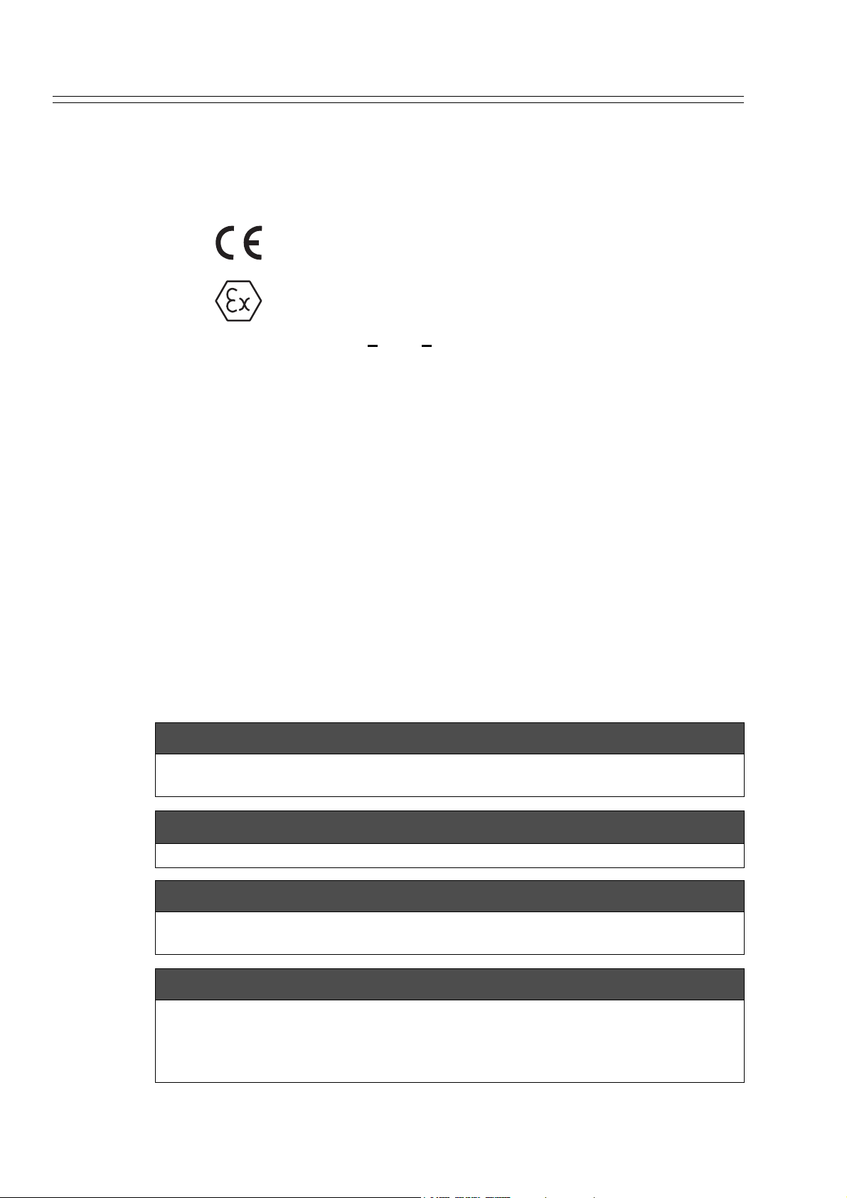
• Seal each conduit entering the apparatus enclosure within 18 in.(457 mm)
from the enclosure.
• Do not open the apparatus enclosure when an explosive atmosphere is
present.
Figure S-1 An example of conduit seal (with stopping plug)
Figure S-2 An example of conduit seals (without stopping plug)
Model HGC303 - Heat Value Gas Chromatograph v
Page 8

Safety Yamatake Corporation
1. Class I, Division 1 locations
1.1 Wiring methods
• Threaded rigid metal conduit, threaded steel intermediate metal conduit, or
Type MI cable with termination fittings approved for the location, can be
employed
• Threaded joints must be made up with at least five threads fully engaged.
• Boxes, fittings, and joints must be approved for Class I, Division 1.
1.2 Sealing
• Each conduit entering the apparatus enclosure is required to be sealed
within 18 in. (457 mm) from the enclosure.
• The sealing of each conduit can be provided with a sealing fitting approved for
class I locations.
• Sealing compound must be approved and must not have a melting point of less
than 93° (200°F).
• The minimum thickness of the sealing compound should not be less than the
trade size of the conduit and, in no case, less than 5/8 in.(16 mm).
• Splices and taps cannot be made in the fittings.
2. Class I, Division 2 locations
2.1 Wiring methods
• Threaded rigid metal conduit, threaded steel intermediate metal conduit,
enclosed gasketed busways, or Type PLTC cable in accordance with the
provisions of remote-control, signaling, and power-limited circuits (see NEC,
Article 725), or Type ITC cable in cable trays, in raceways, supported by
messenger wire, or directly buried where the cable is listed for this use; Type
MI, MC, MV, or TC cable with approved termination fittings can be
employed.
• Boxes, fittings, and joints are not required to be explosionproof.
2.2 Sealing
• Each conduit entering the apparatus enclosure is required to be sealed as shown in 1.2.
3. Class II, Division 1 locations
3.1 Wiring methods
• Threaded rigid metal conduit, threaded steel intermediate metal conduit, or
Type MI cable with termination fittings approved for the location, can be
employed.
• Boxes and fittings must be dusttight.
3.2 Sealing
• Where a raceway provides communication between the apparatus enclosure and
an enclosure that is not required to be dust-ignitionproof, suitable means must be
provided to prevent the entrance of dust into the dust-ignitionproof enclosure
through the raceway. One of the following means can be used: (1) a permanent
and effective seal; (2) a horizontal raceway not less than 10 ft (3.05 m) long; or
(3) a vertical raceway not less than 5 ft (1.52 m) long and extending downward
from the dust-ignitionproof enclosure.
• Seals are not required to be explosionproof.
vi Model HGC303 - Heat Value Gas Chromatograph
Page 9

Yamatake Corporation Safety
4. Class II, Division 2 locations
4.1 Wiring methods
• Rigid metal conduit, intermediate metal conduit, electrical metallic tubing,
dust-tight wireways, or Type MC or MI cable with approved termination
fittings, or Type PLTC in cable trays, or Type ITC in cable trays, or Type
MC or TC cable installed in ladder, ventilated trough, or ventilated channel
cable trays in a single layer, with a space not less than the larger cable
diameter between the two adjacent cables, can be employed.
• All boxes and fittings must be dusttight.
4.2 Sealing
• Sealing means must be provided as shown in 3.2.
5. Class III, Division 1 locations
5.1 Wiring methods
• Rigid metal conduit, rigid non-metallic conduit, intermediate metal conduit,
electrical metallic tubing, dust-tight wireways, or Type MC or MI cable with
approved termination fittings, can be employed.
• All boxes and fittings must be dusttight.
5.2 Sealing
• Sealing means are not required.
6. Class III, Division 2 locations
6.1 Wiring methods
• Wiring methods must comply with 5.1.
6.2 Sealing
• Sealing means are not required.
Model HGC303 - Heat Value Gas Chromatograph vii
Page 10

Safety Yamatake Corporation
viii Model HGC303 - Heat Value Gas Chromatograph
Page 11

Table of Contents
Chapter 1: Introduction
1-1: Definition of terms ......................................................................................... 1-1
1-2: General ......................................................................................................... 1-3
1-3: Model HGC303 measuring system ............................................................... 1-4
1-4: Model HGC303 Structure.............................................................................. 1-5
1-5: Fieldbus communication system................................................................... 1-6
Chapter 2: Installation
2-1: Unpacking and storing .................................................................................. 2-1
2-2: Selecting an interface and installation .......................................................... 2-3
2-2-1: Installing the model HFA100 ........................................................... 2-3
2-2-2: Installing the National Instruments Fieldbus-PC Interface............... 2-7
2-3: HGM installation............................................................................................ 2-8
2-3-1: Computer system requirements ...................................................... 2-8
2-3-2: Windows installation ........................................................................ 2-8
2-3-3: HGM software installation................................................................ 2-9
2-4: Fieldbus installation ...................................................................................... 2-11
2-4-1: Fieldbus requirements ..................................................................... 2-11
2-4-2: Fieldbus wiring................................................................................. 2-13
2-5: Model HGC303 installation ........................................................................... 2-14
2-5-1: Installation site................................................................................. 2-14
2-5-2: Model HGC303 dimensions............................................................. 2-15
2-5-3: Model HGC303 installation example ............................................... 2-16
2-5-4: Model HGC303 piping ..................................................................... 2-17
2-5-5: Model HGC303 wiring ..................................................................... 2-19
Chapter 3: Operation
3-1: Starting up the model HGC303..................................................................... 3-1
3-1-1: Secondary pressure and flow set .................................................... 3-1
3-1-2: Piping leak check............................................................................. 3-1
3-1-3: Power on ......................................................................................... 3-2
3-1-4: Model HGC303 leak check.............................................................. 3-3
3-2: Stopping the model HGC303 ........................................................................ 3-4
3-3: HGM operation.............................................................................................. 3-4
3-3: Introduction ......................................................................................... 3-4
Functions .................................................................................................. 3-4
3-3-1: Getting started with model HFA100................................................. 3-5
3-3-2: Getting started with PCMCIA-FBUS................................................ 3-8
3-3-3: HGM Main menu ............................................................................. 3-14
Page 12

Table of Contents
3-3-4: Set up HGM..................................................................................... 3-15
3-3-5: User's mode menu and commands ................................................. 3-22
3-3-6: Main displays of HGM ..................................................................... 3-23
3-3-7: Report.............................................................................................. 3-28
3-3-8: Configuration mode ......................................................................... 3-31
3-3-9: HGM shut down............................................................................... 3-38
3-4: Calibration..................................................................................................... 3-39
3-4-1: Calibration gas requirement ............................................................ 3-39
3-4-2: Calibration procedure ...................................................................... 3-40
3-4-3: Calibration function.......................................................................... 3-44
3-4-4: Description of component data table ............................................... 3-46
3-4-5: Report.............................................................................................. 3-47
3-4-6: Calibration methods......................................................................... 3-48
3-5: GPA mode .................................................................................................... 3-50
3-5-1: Setting the HGM to GPA ................................................................. 3-50
3-5-2: Data save ........................................................................................ 3-51
3-5-3: Data edit .......................................................................................... 3-51
3-5-4: File auto saving ............................................................................... 3-52
3-5-5: Configuration mode ......................................................................... 3-53
3-5-6: User's mode (GPA).......................................................................... 3-58
3-5-7: Main display panels of HGM (GPA)................................................. 3-60
3-5-8: Report (GPA)................................................................................... 3-65
Chapter 4: Maintenance
4-1: Checking and changing the carrier gas ........................................................ 4-1
4-2: Checking and changing the filters in model HGC303 ................................... 4-1
4-3: Overhaul ....................................................................................................... 4-1
Chapter 5: Troubleshooting
Appendix
GPA calculation.................................................................................................... A-1
Description of normalization method.......................................................... A-1
Formulas .................................................................................................... A-3
ISO calculation ..................................................................................................... A-8
Description of normalization method.......................................................... A-8
Formulas .................................................................................................... A-10
List of replacement parts...................................................................................... A-12
Drawings .............................................................................................................. A-13
Page 13

List of Figure
Figure S-1 An example of conduit seal (with stopping plug) ............................... v
Figure S-2 An example of conduit seals (without stopping plug) ........................ v
Figure 1-1 Model HGC303 measuring system diagram...................................... 1-4
Figure 1-2 Main parts of Model HGC303 ............................................................ 1-5
Figure 2-1 HFA configuration initial display ........................................................ 2-4
Figure 2-2 Model HFA100 operation check display ............................................ 2-5
Figure 2-3 Setup message.................................................................................. 2-9
Figure 2-4 HGM installation location................................................................... 2-9
Figure 2-5 Group name....................................................................................... 2-10
Figure 2-6 Complete installation ......................................................................... 2-10
Figure 2-7 Example of Type A fieldbus cable structure ...................................... 2-11
Figure 2-8 Example of cable finish...................................................................... 2-13
Figure 2-9 Model HGC303 dimension ................................................................ 2-15
Figure 2-10 Example of model HGC303 installation with mounting bracket......... 2-16
Figure 2-11 Piping location ................................................................................... 2-17
Figure 2-12 Wiring location ................................................................................... 2-19
Figure 3-1 Leak check ........................................................................................ 3-3
Figure 3-2 Model HGC303-HGM connection example ....................................... 3-5
Figure 3-3 Model HGC303-HGM connection example ....................................... 3-8
Figure 3-4 Main menu......................................................................................... 3-14
Figure 3-5 Set up HGM display........................................................................... 3-15
Figure 3-6 Example of saved data files (.hv1) .................................................... 3-19
Figure 3-7 User's mode display .......................................................................... 3-22
Figure 3-8 Trend graph of SCV and the total concentration (Raw)..................... 3-24
Figure 3-9 Trend chromatogram (online) ............................................................ 3-25
Figure 3-10 Zoom box........................................................................................... 3-26
Figure 3-11 Trend graph of carrier pressure and oven temp. control ................... 3-27
Figure 3-12 User report entry form ....................................................................... 3-28
Figure 3-13 User report......................................................................................... 3-29
Figure 3-14 Configuration mode display ............................................................... 3-31
Figure 3-15 Calibration setting panel .................................................................... 3-44
Figure 3-16 Component data table ....................................................................... 3-46
Figure 3-17 Preview screen of report.................................................................... 3-47
Figure 3-18 Setup HGM display (GPA)................................................................. 3-50
Figure 3-19 Normalization method setting (GPA) ................................................. 3-50
Figure 3-20 An Example of saved data files (.hv2) ............................................... 3-51
Figure 3-21 Configuration mode display (GPA) .................................................... 3-53
Figure 3-22 Output configuration panel (GPA) ..................................................... 3-54
Figure 3-23 User’s mode display (GPA) ............................................................... 3-58
Figure 3-24 BTU trend graph and the total of raw concentration.......................... 3-62
Figure 3-25 Trend Chromatogram (online) ........................................................... 3-63
Figure 3-26 Trend graph of carrier pressure and oven temp. control ................... 3-64
Figure 3-27 Report entry form (GPA).................................................................... 3-65
Figure 3-28 User report (GPA mode).................................................................... 3-66
Page 14

List of Table
Table 2-1: Fieldbus cable description.................................................................... 2-11
Table 2-2: Conduit type ......................................................................................... 2-15
Table 2-3: Piping description................................................................................. 2-17
Table 2-4: Gas specifications ................................................................................ 2-18
Table 2-5: Wiring description................................................................................. 2-19
Table 3-1 Gas specifications ................................................................................ 3-1
Table 3-2 The procedure to start up the model HGC303 system......................... 3-2
Table 3-3 Model HGC303 leak test procedure ..................................................... 3-3
Table 3-4 Stopping model HGC303 operation ..................................................... 3-4
Table 3-5 Main menu description ......................................................................... 3-14
Table 3-6 Set up HGM description ....................................................................... 3-16
Table 3-7 Set up online mode .............................................................................. 3-17
Table 3-8 Analyzer status and available functions ............................................... 3-18
Table 3-9 Save data description........................................................................... 3-18
Table 3-10 Description of user’s mode display....................................................... 3-22
Table 3-11 Description of the indication panel ....................................................... 3-23
Table 3-12 Trend graph of SCV and total raw concentration description............... 3-24
Table 3-13 Chromatogram description................................................................... 3-25
Table 3-14 Description of trend graph of carrier gas pressure
and oven temperature control .............................................................. 3-27
Table 3-15 Description of user report..................................................................... 3-30
Table 3-16 Description of configuration mode display............................................ 3-32
Table 3-17 Possible configurations of PV12-20 ..................................................... 3-34
Table 3-18 Stopping the HGM................................................................................ 3-38
Table 3-19 Example of calibration action ............................................................... 3-43
Table 3-20 Calibration factor setting....................................................................... 3-45
Table 3-21 Description of component data table.................................................... 3-46
Table 3-22 Manual calibration procedure............................................................... 3-48
Table 3-23 Operating auto calibration procedure................................................... 3-49
Table 3-24 The contents of each line of .hv2 ......................................................... 3-52
Table 3-25 Description of configuration mode display (GPA)................................. 3-53
Table 3-26 Possible configurations of PV12-20 (GPA) .......................................... 3-54
Table 3-27 Description of user’s mode display (GPA)............................................ 3-58
Table 3-28 The difference between ISO and GPA mode in user’s mode............... 3-59
Table 3-29 Indication panel description (GPA)....................................................... 3-60
Table 3-30 Trend graph of BTU and Total raw concentration description.............. 3-62
Table 3-31 Chromatogram description................................................................... 3-63
Table 3-32 Trend graph of Carrier gas pressure and Oven temperature control ... 3-64
Table 5-1 Model HGC303 self-diagnostics........................................................... 5-1
Table A-1 An example of the calculated normalized concentration
and heating value ................................................................................. A-2
Table A-2 Physical constants of selected hydrocarbons
and non-hydrocarbons ......................................................................... A-7
Page 15
Chapter 1 : Introduction
0
1-1 : Definition of terms
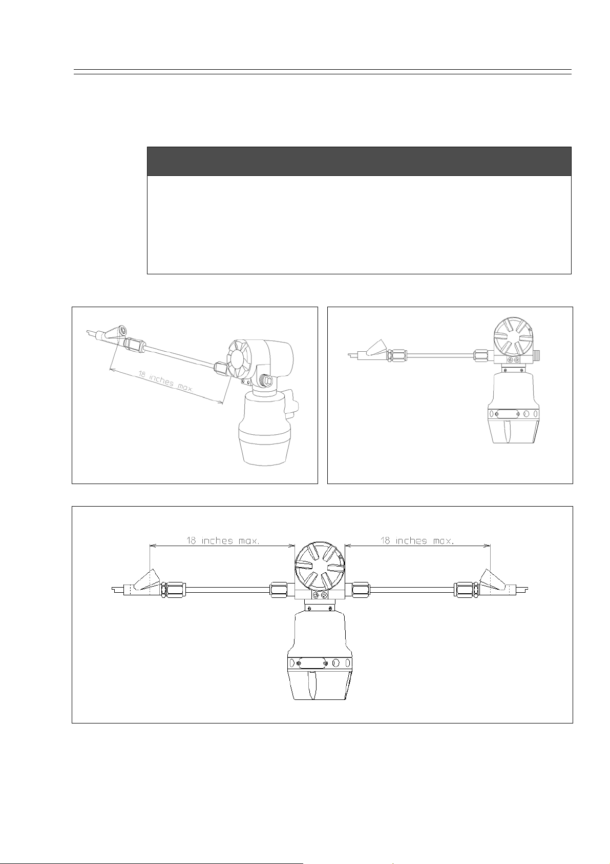
Heat Value Gas Chromatograph (Model HGC303)
The Heat Value Gas Chromatograph measures process gases (N2,
CO2, C1~C6+) that are mainly contained in natural gas, calculates
heat value, density, Wobbe index and compressibility factor, and
converts them into a Fieldbus signal in the field and transmits the
signal to a receiver.
Parameters can all be remotely set, adjusted, and self-diagnosed by
using the HGM.
Measuring and calculating methods comply with ISO 6974 Part 4 and
ISO 6976.
HGC Modbus Interface Unit (Model HMU303)
The model HMU303 Modbus Interface can convert a
Fieldbus signal into a Modbus signal.
HGC000
Monitoring of such data as heat value can be done using a
Modbus signal as well as a Fieldbus signal.
See the model HMU303 User's manual for more details.
HGC Data Manager (Model HDM303)
Model HDM303 is Modbus interface unit for model HGC303.
Model HDM303 covers all the function of model HMU303.
Model HDM303 also has a powerful functions.
The functions are local display, data storage function, multi
Modbus serial port, multi stream switching, and analog output.
HMU can not be connected together with HDM in the same FB
loop. Only one HMU can be connected in one FB loop with the
HGC. Two or more HDM can be connected in the same FB
loop. For this application, the HDM must be configured first.
Please refer to the model HDM303 User's Manual for more details.
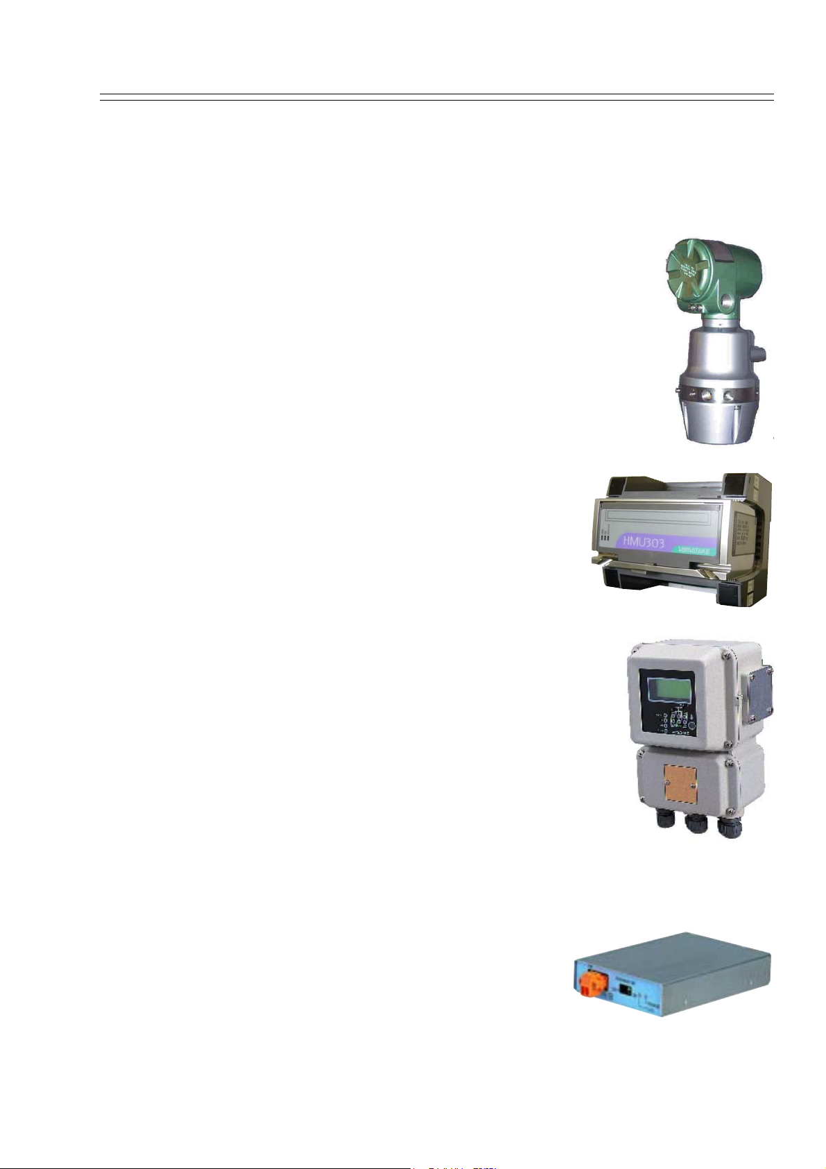
Heat Value Gas Chromatograph Fieldbus Adaptor (Model HFA100)
HFA is an interface used to connect the HGM (HGC
monitor), Windows-based PC application, to
Yamatake’s state of the art analyzer, HGC (Heat value
Gas Chromatograph) that operates on FOUNDATION™
fieldbus H1 network. Users are able to configure,
monitor and maintain the HGC all from the PC by
simply connecting the HFA to the Fieldbus network.
Model HGC303 - Heat Value Gas Chromatograph 1-1
Page 16

Introduction Yamatake Corporation
HGC Monitor (HGM)
HGM software is provided as a standard accessory
with the model HGC303.
The model HGC303 Monitor allows the user to configure and calibrate the model HGC303 as well as
allowing one to monitor a heat value-trend graph.
Moreover, HGM also has a report function for concise management.
HGM000001000P
SP (Set Point)
The set value of each variable.
PV (Process variable)
The present value of each variable.
SCV
ICV
TCD
URV
LRV
Total (Raw)
Component name
Superior Calorific Value
Inferior Calorific Value
Thermal Conductivity Detector
Upper Range Value
Lower Range Value
Total of raw concentration
C6+: Hexane and heavier gas
C3H8: Propane
i-C4H10: i-Butane
n-C4H10: n-Butane
neo-C5H12: neo-Pentane
i-C5H12: i-Pentane
n-C5H12: n-Pentane
N2: Nitrogen
CH4: Methane
CO2: Carbon dioxide
C2H6: Ethane
1-2 Model HGC303 - Heat Value Gas Chromatograph
Page 17

Yamatake Corporation Introduction
1-2 : General
The model HGC303 is a gas chromatograph designed to analyze natural gas and is
able to transmit a process variable via a Fieldbus signal.
One can easily adjust configuration data and monitor values such as the heat value by
using the HGM.
The heat value monitoring system, which can be controlled from both the model
HGC303 and HGM, will substantially minimize time, cost and maintenance.
This chapter first describes the measuring system and structure of the model HGC303.
After that, the characteristics and the specifications of Fieldbus are described in detail.
First time users of the model HGC303 should read this chapter carefully and thoroughly.
Components of the model HGC303 system
Before installing the model HGC303, the following components must be prepared:
Hardware
Model HGC303
Model HMU303
Model HFA100
Power supply (24 V DC, 4A min.), Power supply cable
Fieldbus cable (See “2-4-1 : Fieldbus requirements” on page 2-11)
Flow meter for process gas
(A flow meter for methane should be used scale: 0 - 200 ml/min.)
Laptop or desktop PC
(See “2-3-1 : Computer system requirements” on page 2-8 for detail)
The National Instruments Fieldbus-PC interface*
(See “2-2-2 : Installing the National Instruments Fieldbus-PC Interface” on page 2-7 for
detail)
Helium gas for carrier gas and valve operating gas
Calibration gas
1/8 inch stainless steel (SS) tubing
Fitting for piping (1/4 NPT male, 5 pieces)
Software
Microsoft Windows 98 / Me / NT / 2000 / XP
HGM
~Note *: This is not necessary if using the model HFA100. However, the model
HFA100 can only run on Windows 2000 / XP. If you are running an
operating system other than Windows 2000 / XP, purchase the National
Instruments Fieldbus-PC Interface.
Model HGC303 - Heat Value Gas Chromatograph 1-3
Page 18
Introduction Yamatake Corporation
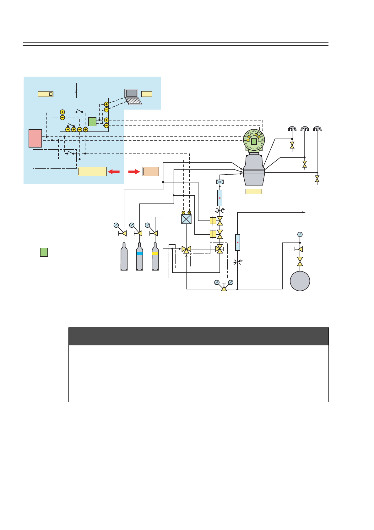
1-3 : Model HGC303 measuring system
Modbus
RS2320
HMU-
Modbus
Converter
PS
POWER
DC
24V
Manual
*
Switch
(for manual
calibration)
: Terminator
T
Required for manual calibration.
*
(at least one of them)
or
RS422/RS485
T
ALARM 50L RELAY
FB
Safe Area Field
AIR/N2/He He Standard
350 - 450 kPa
350 - 450 kPa
HGM
Gas
Fieldbus
Solenoid
valve
(24V DC)
Sampling
flow meter
3-way
*
valve
(for manual
calibration)
Inline
Filter
AIR
CARR
INLET
50ml/mh
Needle
valve
Block
valve
Block
valve
POWER
T
HGC303
Bypass
flow meter
Needle
valve
Sample Gas
OUTPUT
AIR VENT
VENT (Open to Air)
TCD-VENT
OUTLET
RETURN to
low pressure
line
NG
PIPE LINE
Figure 1-1 Model HGC303 measuring system diagram
CAUTION
A block valve is a kind of air actuator valve. It is used mainly for the protection of
the TCD and columns.
It works as sample shut-off valve when the pressure of the carrier gas or air supply
is lower than approximately 294 kPa.
Yamatake recommends that it should be installed.
The Heat Value Gas Chromatograph measures process gases (N2, CO2, C1~C6+) that
are mainly contained in natural gas, calculates heat value, density, Wobbe index and
compressibility factor, and converts them into a Fieldbus signal in the field and transmits the signal to receivers.
Parameters can be remotely set, adjusted, and self-diagnosed with the HGM.
1-4 Model HGC303 - Heat Value Gas Chromatograph
Page 19
Yamatake Corporation Introduction
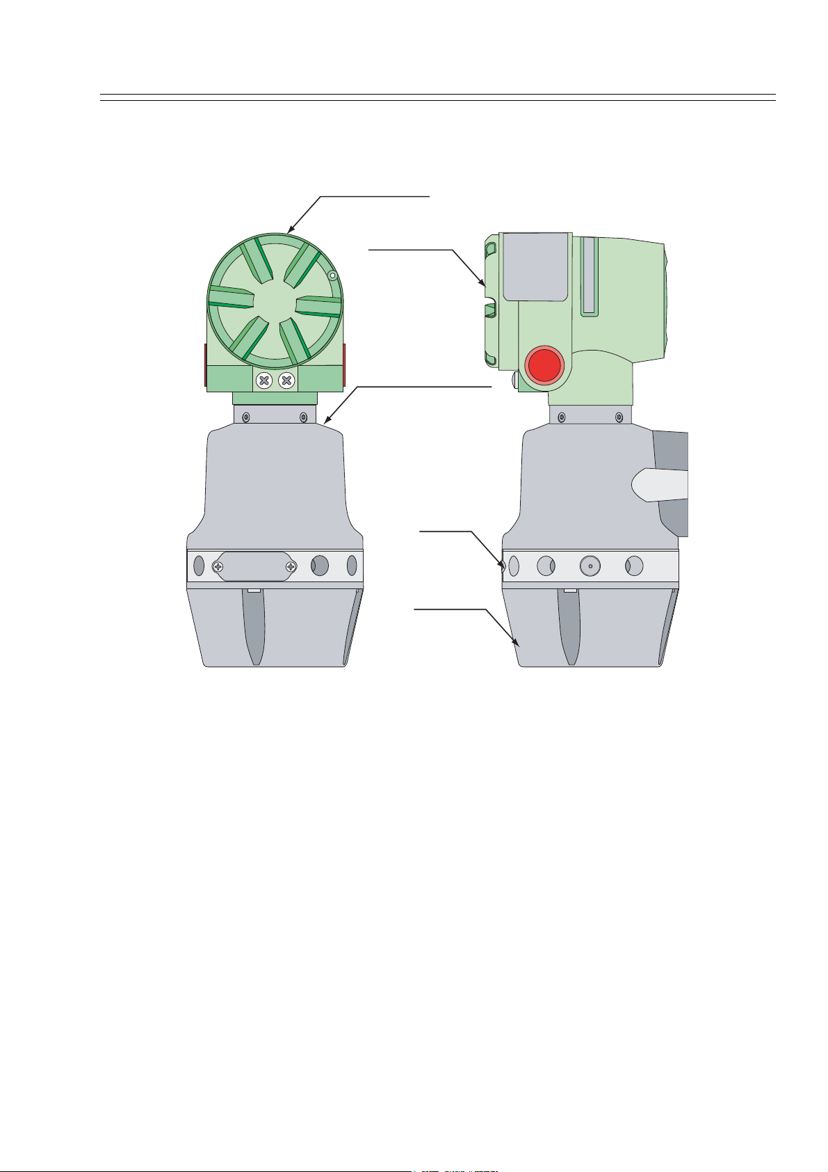
1-4 : Model HGC303 Structure
Terminal housing
Terminal cover
Analyzer unit housing
Manifold
Oven cover
HGC000004000D
Figure 1-2 Main parts of Model HGC303
1 Terminal housing ..........Terminal box for wiring.
2 Analyzer unit housing...Micro valve, solenoid valve, TCD sensor are located here.
3 Manifold........................Connection parts for gas inlet and outlet line
4 Oven cover....................Analyzer valve and column system are found inside the
cover.
Model HGC303 - Heat Value Gas Chromatograph 1-5
Page 20

Introduction Yamatake Corporation
1-5 : Fieldbus communication system
The model HGC303 uses FOUNDATION™ fieldbus technology to transfer information
between other devices.
The FOUNDATION™ fieldbus is an open, 2-wire, multi-drop, two-way digital commu-
nication system which interconnects field equipment such as sensors, actuators and
controllers.
The FOUNDATION™ fieldbus is supported by a worldwide network of customers and
manufacturers in Europe, North America and Asia Pacific.
FOUNDATION™ fieldbus http://www.fieldbus.org/
FOUNDATION™ fieldbus literature
(1) FOUNDATION™ fieldbus Technical overview (FD-043)
(2) Fieldbus Installation & Planning Guide (AG-165)
(3) FOUNDATION™ fieldbus Application Guide
31.25kbit/s Wiring and Installation (AG-140)
(4) FOUNDATION™ fieldbus Application Guide
31.25kbit/s Intrinsically Safe Systems (AG-163)
1-6 Model HGC303 - Heat Value Gas Chromatograph
Page 21
Chapter 2 : Installation
This chapter guides you through the procedures for installing of your hardware and
software.
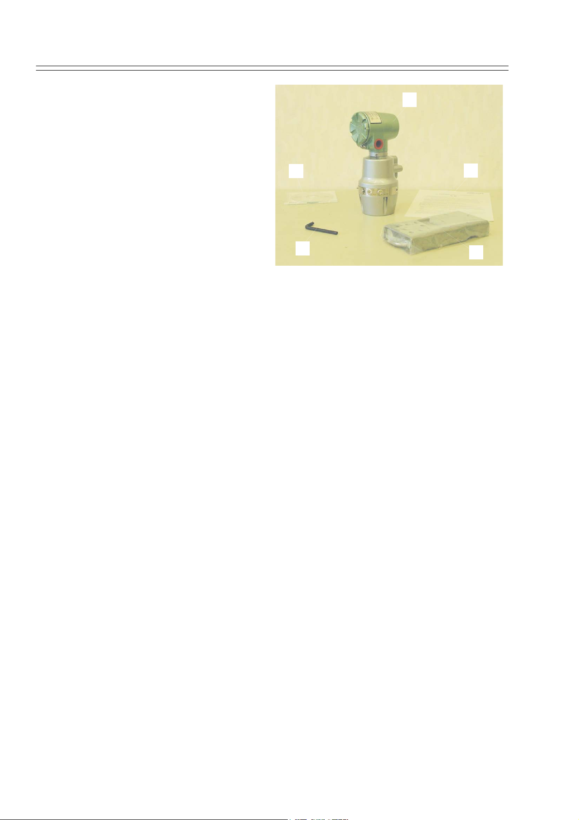
2-1 : Unpacking and storing
Unpacking the model HGC303
Your model HGC303 is a precision instrument and should be handled with care to prevent any damage to it or breaking it.
After unpacking the model HGC303, verify that the following items are included:
Package items
(1) Model HGC303
(2) Mounting bracket set
(3) Wrench for seal plug
(4) CD-ROM including HGM software and user's manual
(5) EC declaration of conformity and safety instructions
CAUTION
Exposing the model HGC303 to the atmosphere might cause deterioration of the
column. Therefore, the model HGC303 has been packed and shipped in a protective
bag with a desiccant. Install and operate the model HGC303 immediately after
breaking the seal.
Model HGC303 - Heat Value Gas Chromatograph 2-1
Page 22
Installation Yamatake Corporation
Inquires
If you have any questions regard-
(1)
ing the specifications of your
model HGC303, contact one of the
Yamatake products service offices
listed at the back of this user's
manual or contact your nearest
(4)
(5)
Yamatake representative.
When making an inquiry, make
sure to provide the model number
and product number of your model
HGC303.
(3)
(2)
HGC000002000P
2-2 Model HGC303 - Heat Value Gas Chromatograph
Page 23
Yamatake Corporation Installation
Storing the model HGC303
The model HGC303 should be stored:
- indoor at storage temperature (-40 to 70°C); humidity (up to 95%RH)
- in a place safe from vibration or shock.
- in the same packing as it was shipped in.
Model HGC303 that has been used should be stored by following procedures below.
Step Action
1 Makes sure no process gas remains in the model HGC303.
2 Purge the model HGC303 with helium gas.
Insert metal plugs into all the inlets and outlets for carrier
3
gas, valve operating gas and process gas except VENT
(valve operating gas outlet) in order to keep moisture out.
4 Pack it as it was when it was originally received.
5
Store the model HGC303 indoors at normal temperature
and humidity in a place safe from vibration or shock.
Model HGC303 - Heat Value Gas Chromatograph 2-3
Page 24

Installation Yamatake Corporation
2-2 : Selecting an interface and installation
The HGM requires a data converter to convert the data that is being received from the
HGC. You may use either 1) the Yamatake Heat Value Gas Chromatograph Fieldbus
Adaptor (model HFA100) or 2) the National Instruments Fieldbus-PC Interface.
CAUTION
Model HFA100 operates only on Windows2000 / XP. Purchase the National Instruments Fieldbus-PC Interface if you are running an operating system other than Windows 2000/XP.
~Note 1. A PC with a USB1.0 port is required to run the model HFA100.
2. For the National Instruments Fieldbus-PC Interface, you additionally
have to prepare a floppy disk drive and a PC having either a type-II
PCMCIA socket or a 16-bit ISA slot.
2-2-1 : Installing the model HFA100
Installing the hardware:
Refer to the model HFA100 instruction manual.
Installing the software:
In order to use the model HFA100, following two softwares must be installed.
1. HFA Config.exe (Installed at the same time the HGM is installed)
2. HFBADRV (An USB driver for model HFA100)
Procedure for software installation
(1) First install the HGM by following instructions found in section 2-3 “HGM Instal-
lation” below.
An installation CD-ROM comes supplied with your model HGC303. Take note that
there are two types of “Setup HGM” folders on the CD-ROM: (1) Setup HGM for
HFA and (2) Setup HGM for NI.
To use the model HFA100, you must select the {setup} icon that is in the “Setup
HGM for HFA” folder. If you by chance install from the “Setup HGM for NI”
folder, uninstall it, and then install from the “Setup HGM for HFA” folder.
(2) Once HGM installation has completed, install 'HFBADRV'.
CAUTION
When connecting the model HFA100 to a USB port, an installation wizard will
appear on your screen. Follow the instructions that the installation wizards give
you. You will be asked for your CD-ROM that came with the model HGC303
where you should select the folder “HFBADRV”. (Once the file ‘HFBADRV’ is
installed, cannot be uninstalled.)
2-4 Model HGC303 - Heat Value Gas Chromatograph
Page 25
Yamatake Corporation Installation
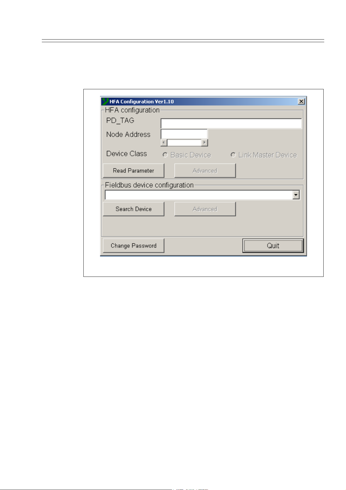
(3) Checking after installation
Connect the model HFA100 to the PC, and then start HFA Config.exe (Default
directory: C:\Program file\HGM), which is in the HGM folder. A dialog box like
that shown in Figure 2-1 will appear.
Figure 2-1 HFA configuration initial display
Model HGC303 - Heat Value Gas Chromatograph 2-5
Page 26
Installation Yamatake Corporation
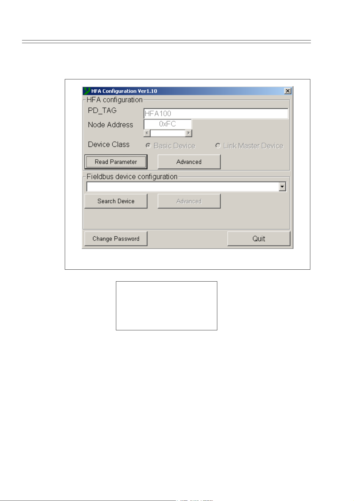
Click on the Read Parameter button. If PD_TAG, Node Address and Device Class
appear on the display as they do below, the driver has been installed correctly. (See
Figure 2-2).
Figure 2-2 Model HFA100 operation check display
Default Setting
PD_TAG: HFA100
Node Address: 0×FC
Device Class: Basic Device
This completes your model HFA100 installation. Refer to “3-3 : HGM operation”
when using the model HFA100 connected to a HGM.
2-6 Model HGC303 - Heat Value Gas Chromatograph
Page 27
Yamatake Corporation Installation
~Note
*Installing and Uninstalling the model HFA100
Installing: Connect the model HFA100 to the PC’s USB port. An new icon will
appear on the taskbar.
Uninstalling:Select the “Stop HFBADRV (HFA100 FB Adapter)” from the task-
bar.
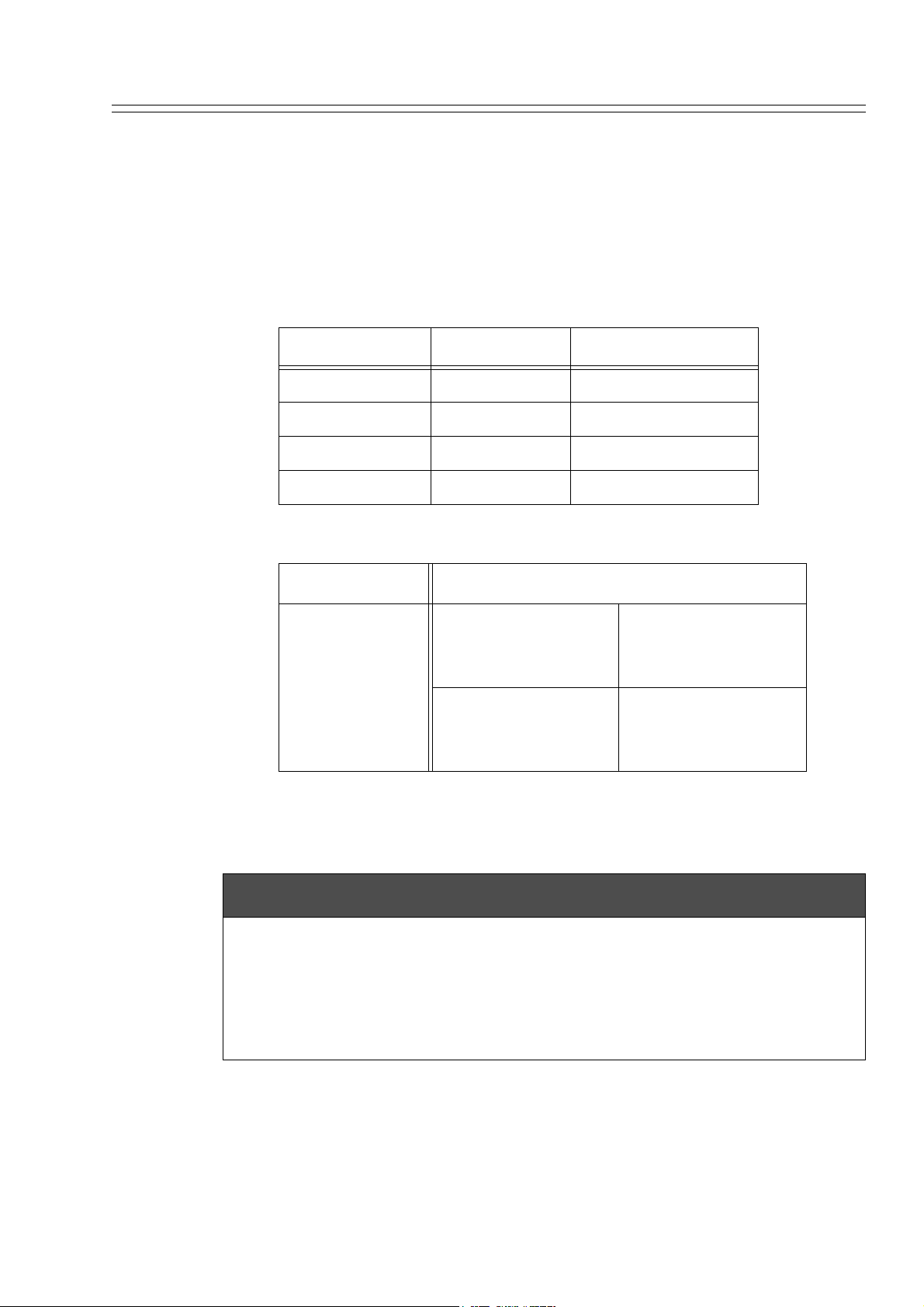
* Default setting of HGC system device (normally no change required)
Model No. PD_TAG Node address
HGC303 HGC 0×F7
HMU303 HMU 0×10
HDM303 HDM303 0×10
HFA100 HFA100 0×FC
Usable setting range
PD_TAG First three characters must be model No.
0×10 - 0×13
HMU system
Node address
HDM system
FB initialization should be done when either PD_TAG or Node Address is
changed.
0×E0 - 0×F7
0×FC - 0×FF
0×10 - 0×24
0×E0 - 0×F7
0×FC - 0×FF
CAUTION
* The device has been factory set for the user's application therefore the default
value should suit your process. However, when changing the settings, have a thorough understanding of the parameters beforehand.
* “Fieldbus device configuration” is only for authorized service personnel. If the
“Fieldbus device configuration” button is clicked, shutdown at once and then restart
“HFA Config.exe”.
Model HGC303 - Heat Value Gas Chromatograph 2-7
Page 28

Installation Yamatake Corporation
2-2-2 : Installing the National Instruments Fieldbus-PC Interface
For instructions on installing the National Instruments Fieldbus-PC Interface, refer to
the instruction manual packed with the product. Once installation is completed, proceed to “2-3 : HGM installation” in this manual for HGM installation procedures. To
install the HGM, select the {setup} icon from the folder “Setup HGM for NI” found
on the installation CD-ROM.
Reference:
The National Instruments Fieldbus-PC interface
Manufacturer: National Instruments
http://www.natinst.com/
Requirements
(1) PCMCIA Type
Product name: PCMCIA-FBUS (1 port)
Model number: 777282-01
Includes: 1) Fieldbus Interface for PCMCIA
2) NI-FBUS Communication Manager Software
3) PCMCIA-FBUS Cable (1 port)
4) Documentation Kit
(2) ISA board Type
Product name: AT-FBUS (1 port)
Model number: 777281-01
Includes: 1) Fieldbus Interface ISA board
2) NI-FBUS Communication Manager Software
3) Documentation Kit
2-8 Model HGC303 - Heat Value Gas Chromatograph
Page 29

Yamatake Corporation Installation
2-3 : HGM installation
2-3-1 : Computer system requirements
(1) Computer: DOS/V compatible,
Minimum 200 MHz Pentium processor.
(2) System memory: 64 MB minimum
(3) Disk storage: 100 MB free space
(4) CD-ROM drive
(5) Operating system: Windows 98 / Me / NT / 2000 / XP
(6) Video Monitor: Microsoft Windows 98 / Me / NT / 2000 / XP, 100% compatible,
including a display resolution of 1024×768 or higher and high color of 16 bit or
higher.
(7) Printer: Must be 100% compatible with Microsoft Windows 98 / Me / NT / 2000 /
XP.
2-3-2 : Windows installation
Before installing the HGM, Windows 98 / Me / NT / 2000 / XP must be installed and
running as an operating system on your computer.
~Note Install the latest service pack of Windows.
Model HGC303 - Heat Value Gas Chromatograph 2-9
Page 30
Installation Yamatake Corporation
2-3-3 : HGM software installation
Installing the HGM
(1) Make sure Windows 98 / Me / NT / 2000 / XP has been installed.
(2) Insert the CD-ROM into the CD-ROM drive.
(3) Double-click on the [Setup HGM] folder.
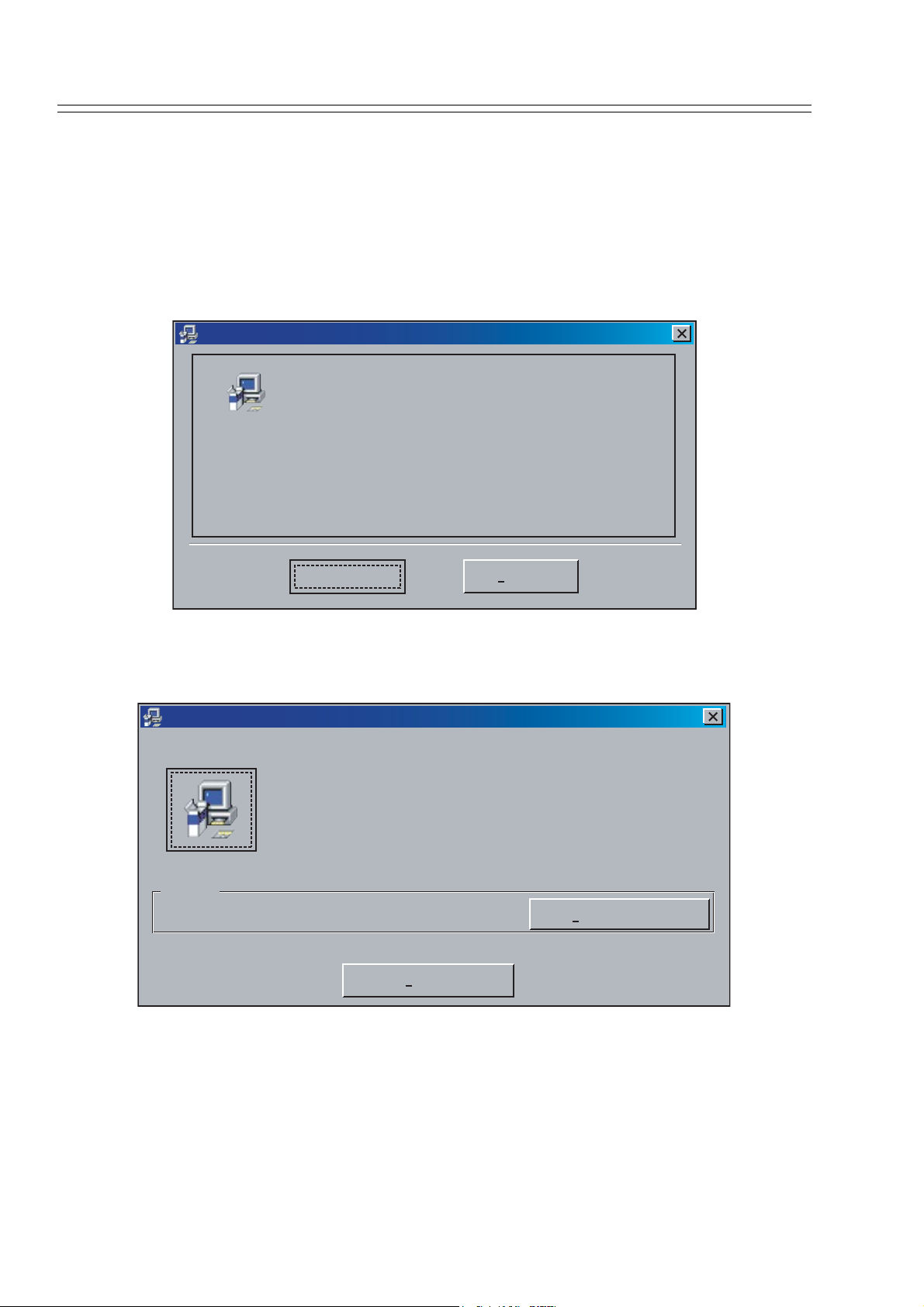
(4) Double-click on the [setup] icon. The following screen will appear:
HGC Monitor Version 2.00 Setup
Welcome to the HGC Monitor Version 2.00 installation
program.
Setup cannot install system files or update shared files if they are in
use. Before proceeding, we recommend that you close any applications
you may be running.
OK
Exit Setup
Figure 2-3 Setup message
Click on [OK] and the following display will appear:
HGC Monitor Version 2.00 Setup
Begin the installation by clicking the button below.
Click this button to install HGC Monitor Version 2.00 software to the specified
destination directory.
Directory:
C:\Program Files\hgm\
Exit Setup
Change Directory
Figure 2-4 HGM installation location
Default directory: C:\Program Files\hgm
If you want to use another drive or directory, select an optional drive or directory by
pressing the [Change Directory] button.
2-10 Model HGC303 - Heat Value Gas Chromatograph
Page 31

Yamatake Corporation Installation
HGM000004000S
Figure 2-5 Group name
Click on [Continue].
If a version conflict message appears, select [Yes].
Installation is complete once the message below appears on your screen.
HGM000005000S
Figure 2-6 Complete installation
Refer to “3-3 : HGM operation” on page 3-4.
Model HGC303 - Heat Value Gas Chromatograph 2-11
Page 32

Installation Yamatake Corporation
2-4 : Fieldbus installation
2-4-1 : Fieldbus requirements
Fieldbus components and characteristics
Cable
Various types cables are usable for fieldbus.
Type A is the preferred fieldbus cable.
Yamatake recommends type A as the fieldbus cable to use.
The table below describes the type of cable and its maximum length, which is specified in the IEC 1158-2/ISA S50.02 Physical Layer Standard.
Table 2-1: Fieldbus cable description
Type Cable description Size Maximum length
A Shielded, twisted pair
#18 AWG (0.8 mm2)
1900m (6232 ft.)
Structure: twisted pair cable with overall shield
Detailed specifications of the Type A cable at 25°C are as follows;
a) Characteristic impedance: Z0 at 31.25 kHz = 100 ohm +/- 20%
b) Maximum attenuation at 39 kHz = 3.0 db/m
c) Maximum capacitive unbalance to shield = 2 nF/km
d) Maximum DC resistance (per conductor) = 22 ohm/km
e) Maximum propagation delay change 7.8 kHz to 39 kHz = 1.7 us/km
f) Conductor cross-sectional area (wire size) = 0.8 mm2 (#18 AWG)
g) Minimum shield coverage shall be 90%
Support
Conductor
Insulator
Taping
Shield foil
Shield wire
Shield net
Jacket
Figure 2-7 Example of Type A fieldbus cable structure
2-12 Model HGC303 - Heat Value Gas Chromatograph
Page 33

Yamatake Corporation Installation
Terminators
A terminator is an impedance matching module used near or at the end of a transmission line. Terminators prevent distortion and signal loss.
A terminator shall be located at both ends of a trunk cable, connected from one signal
conductor to the other.
A trunk is the longest cable path between any two devices on the fieldbus network.
ONLY TWO terminators are required per fieldbus segment.
No connection shall be made between the terminator and cable shield.
The terminator impedance value shall be 100 ohm +/- 2% over a frequency range of
7.8 kHz to 39 kHz.
The model HGC303 and model HMU303 have a terminator at the fieldbus connection
port therefore an additional terminator is not required.
Terminal blocks
The terminal blocks can be the same as those used for 4-20mA.
Connectors
D-sub 9P connector is as specified for standard fieldbus connectors in the IEC/ISA
Standard.
Contact No. Signal
6Data +
7Data -
Model HGC303 - Heat Value Gas Chromatograph 2-13
Page 34

Installation Yamatake Corporation
2-4-2 : Fieldbus wiring
Signal wire
A Fieldbus signal is transmitted via 2-wire isolated signal lines.
Please keep in mind that the Fieldbus signal has polarity, positive (+) and negative (-).
All of the (+) terminals must be connected to each other and similarly, all of the (-) terminals must be connected each other.
An important aspect of fieldbus is that neither of the signal wires are grounded.
Shielding
The preferred type of cable for fieldbus is a shielded cable.
Assemble a lugged shield wire connected to the metallized shield of each cable.
Connect all shield wires together to the terminal block.
In addition, connect the overall shield to the ground at one point in instruments room
to protect against field noise.
Do not ground the shield at multiple points.
Termination
A terminator shall be connected at both ends of the signal wire pair, at the field device
end and the host device end.
Connect the terminator between signal (+) and (-).
ONLY TWO terminators are needed per fieldbus segment.
Never connect a terminator between the signal (+ or -) and cable shield.
Heat shrink sleeve
Twiseted pair wire
Jacket
Overall shield
Shield wire
Wire terminal
Figure 2-8 Example of cable finish
2-14 Model HGC303 - Heat Value Gas Chromatograph
Page 35

Yamatake Corporation Installation
2-5 : Model HGC303 installation
2-5-1 : Installation site
Conditions for selecting a location for installation.
- A sheltered location conforming to class C as defined by IEC654-1.
This is so to protect the model HGC303 from direct sunlight, wind, and rain.
Select a site that allows for the installation of a housing structure or protective panels.
- A location which is free from sudden changes in temperature or humidity and
which has an ambient temperature within the range of -10 to 50°C and a relative
humidity range of 95% maximum.
- A location not subject to electromagnetic induction, as such as that generated by
large - scale transformers and high-frequency furnaces.
- A location not subject to severe vibration.
- A location with minimal exposure to corrosive gases or dust and with good air circulation.
Model HGC303 - Heat Value Gas Chromatograph 2-15
Page 36

Installation Yamatake Corporation
2-5-2 : Model HGC303 dimensions
The dimensions of the model HGC303 are given below.
[Unit: mm (inch)]
77 (3.0)
115 (4.5)
97 (3.8)82 (3.2)
244 (9.6)
100 (3.9)
Figure 2-9 Model HGC303 dimension
A workspace should be selected taking into consideration facilitation of wiring, piping, and maintenance.
Table 2-2: Conduit type
Model No. Gas connection Conduit entry
Model HGC303-1E 1/4 NPT 1/2 NPT
Model HGC303-1F 1/4 NPT 1/2 NPT
2-16 Model HGC303 - Heat Value Gas Chromatograph
Page 37

Yamatake Corporation Installation
2-5-3 : Model HGC303 installation example
Install the model HGC303 as shown in following diagrams.
The weight of the model HGC303 with mounting bracket is 5 kg / 11 lbs.
2in. pipe
Hexagon head bolt
Mounting bracket
Figure 2-10 Example of model HGC303 installation with mounting bracket
HGC000008000D
Mounting position: Mount the model HGC303 horizontally.
Model HGC303 - Heat Value Gas Chromatograph 2-17
Page 38

Installation Yamatake Corporation
2-5-4 : Model HGC303 piping
Refer to this section before designing and installing the gas inlet, gas outlet and vent
lines.
The mark [N] on the manifold refers to 1/4 NPT connection.
Left side view Front view Right side view
Figure 2-11 Piping location
Table 2-3: Piping description
Model
Part
HGC303
Description
marking
Carrier gas inlet Carr
Valve operating gas
inlet
Valve operating gas
outlet
AIR
VENT
Inlet for introducing the carrier gas into the column of the analyzer unit.
Inlet for introducing the valve operating gas into
the analyzer unit.
Outlet valve operating gas.
Do not remove this vent plug.
Process gas inlet INLET Inlet for introducing the process gas.
Process gas outlet OUTLET Outlet for process gas.
Measured gas outlet TCD-VENT
Outlet for mixture of measured gas and carrier gas
after analysis.
HGC000009000P
2-18 Model HGC303 - Heat Value Gas Chromatograph
Page 39

Yamatake Corporation Installation
WARNING
Purge the carrier gas line before performing any piping, and then verify that there is
no dust remaining in the piping.
Release the gas from the vent line to the air through the header.
There is a possibility that back-pressure from vent line has a lot of influence.
Prepare the carrier gas and valve operating gas as specified in the table below.
Table 2-4: Gas specifications
Gas type Purity
Carrier gas Helium 99.99% or higher
Valve operating
gas
Process gas Natural gas -
Helium, Air,
Nitrogen
99.99% or higher
Secondary supply
pressure
400 ± 50 kPa
(58 ± 7 psi)
400 ± 50 kPa
(58 ± 7 psi)
50 - 490 kPa (7 - 71 psi)
at flow meter inlet
Model HGC303 - Heat Value Gas Chromatograph 2-19
Page 40

Installation Yamatake Corporation
2-5-5 : Model HGC303 wiring
Remove the terminal cover and wiring while referring to the figure and table below.
Figure 2-12 Wiring location
Either internal grounding (earthing) terminal (A) or external grounding (earthing) terminal (B) can be used.
At least one grounding (earthing) terminal connection is recommended.
Table 2-5: Wiring description
Terminal No. Description
1 Power supply (-)
2 Power supply (+)
3 No connection
4 FB terminal (-)
5 FB terminal (+)
6 No connection
7 Terminator (-)
8 Terminator (+)
A Internal GND
B External GND
~Note Yamatake recommends cable of conductor cross-sectional area 2 (mm²) or
equivalent for power supply connection and GND connection.
2-20 Model HGC303 - Heat Value Gas Chromatograph
Page 41

Yamatake Corporation Installation
WARNING
Only a 24V DC supply may be used to operate the model HGC303.
Model HGC303 - Heat Value Gas Chromatograph 2-21
Page 42

Installation Yamatake Corporation
2-22 Model HGC303 - Heat Value Gas Chromatograph
Page 43

Chapter 3 : Operation
3-1 : Starting up the model HGC303
3-1-1 : Secondary pressure and flow set
Adjust the pressure of the following gas types as specified by the corresponding
pressure on the right.
Table 3-1 Gas specifications
Gas type Secondary supply gas pressure and flow rate
Carrier gas 400 ± 50 kPa (58 ± 7 psi)
Valve operating gas 400 ± 50 kPa (58 ± 7 psi)
Process gas 50 ± 20 ml/min.
3-1-2 : Piping leak check
Before starting up the model HGC303, conduct a leak test to verify there is no leakage
of gas from the piping connection.
A leak test using soap bubbles will be sufficient.
If a leak found:
(1) Tighten the fittings.
(2) Replace the fittings.
Model HGC303 - Heat Value Gas Chromatograph 3-1
Page 44

Operation Yamatake Corporation
3-1-3 : Power on
Supply the power to operate the model HGC303 system according to the following
action.
Table 3-2 The procedure to start up the model HGC303 system
Step Action
1 Supply the valve operating gas
2 Supply the carrier gas pressure
3 Supply the power to the model HGC303
4 Supply the power to the model HMU303
5 Wait until the model HGC303 system becomes stale.
6 Supply the process gas
~Note After turning on the power, allow 2 hours for the device to warm up.
The carrier gas pressure SP and oven temperature SP have already been factory set in
the model HGC303, therefore, the user doesn't have to worry about setting this data.
Carrier gas pressure SP: less than 300 kPa (43.5 psi)
(SP differs with each model HGC303)
Oven temperature SP: 58°C (136.4°F)
Analyzing cycle: 300 sec.
~Note When the power is supplied to the model HGC303, a model HGC303
status error will appear on HGM monitoring system (oven temperature
error message etc.
This is because of a self-diagnostic system error, not a model HGC303
system error.
The model HGC303 status will automatically return to normal once the
oven temperature reaches 58°C (136.4°F).
3-2 Model HGC303 - Heat Value Gas Chromatograph
Page 45

Yamatake Corporation Operation
3-1-4 : Model HGC303 leak check
After turning the model HGC303 on, conduct a leak test to verify that there is no
leakage of gas from the model HGC303.
The following procedures are for a simple leak test for the carrier gas line.
Carry out the leak test for the valve operating gas line in the same way.
(A)
(B)
HGC000011000D
Figure 3-1 Leak check
Table 3-3 Model HGC303 leak test procedure
Step Action
1 Check that the valve operating gas is being supplied.
2 Check the carrier gas has a secondary pressure (A) of 400 ± 50 kPa (58 ± 7
psi).
3 Verify that the carrier gas line valve off and observe the rate of fall in the
indicated primary pressure (B).
4 Leak evaluation procedure.
After introducing the carrier gas into the model HGC303, a normal condition is confirmed by a rate of fall of less than 1500 kPa (217 psi) per every 5
minutes.If more than 1500 kPa (217 psi) is observed, immediately contact a
Yamatake products service office listed at the back of this manual.
If the carrier gas is being used for valve operating gas at the same time, the
carrier gas consumption will be doubled. (less than 3000 kPa (435 psi) per 5
minutes)
CAUTION
Verify that there is no leak from all connections.
Model HGC303 - Heat Value Gas Chromatograph 3-3
Page 46

Operation Yamatake Corporation
3-2 : Stopping the model HGC303
To stop model HGC303 operation, follow the procedures listed below.
Table 3-4 Stopping model HGC303 operation
Step Action
1 Shut off the process gas line.
2 Turn off the model HMU303 power.
3 Turn off the model HGC303 power.
4 Shut off the carrier gas line.
5 Shut off the valve operating gas line.
6 Refer to “ Storing the model HGC303” on page 2-2 when removing the
model HGC303 from the field.
3-3 : HGM operation
Introduction
The functions of the HGM are described in this chapter.
The HGM is a calibration, configuration and maintenance tool for the model HGC303.
Analysis statuses, process variables and a chromatogram are displayed on its screen,
and information is stored in a database to facilitate routine management and tuning.
~Note 1 There is a possibility that this software will not function properly if
~Note 2 Please use a period “.” as a decimal symbol.
Functions
(1) Monitoring heat value, chromatogram and carrier gas pressure / oven temperature
(2) Data save (load)
(3) User report
(4) Calibration
(5) Self-diagnostics
(6) Hold model HGC303 outputs to host control system
another application software is used at the same time.
There is a possibility that analysis data will not save properly if a
comma “,” is used.
Select Start >> Settings >> Control Panel >> Regional Settings and
then click on Number Tag
Set decimal symbol to period “.”.
control
If using the model HFA100, proceed to the next page. If using the “PCMCIA-FBUS”, proceed to
section “3-3-2 : Getting started with PCMCIA-FBUS”.
3-4 Model HGC303 - Heat Value Gas Chromatograph
Page 47

Yamatake Corporation Operation
3-3-1 : Getting started with model HFA100
HGM connection with model HFA100 and model HMU303
HGM connection is possible at any location along the FB line.
Connect the HGM as shown in the picture below.
Figure 3-2 Model HGC303-HGM connection example (combination of model HGC303,
model HGU303 and model HFA100)
Refer to the model HMU303 user’s manual regarding the details of each part of the
model HMU303.
Model HGC303 - Heat Value Gas Chromatograph 3-5
Page 48

Operation Yamatake Corporation
Starting up the HGM with model HFA100
The procedure to start the HGM up are given below.
1. Make sure that both the model HGC303 and the model HMU303 are running normally.
2. Prepare a personal computer, which has the HGM installed.
3. Make sure the computer is running Windows 2000 / XP.
4. Verify that font size is [Small font] and the display resolution 1024 × 768 pixels.
5. Connect the model HFA100 along the FB line. (Refer to Figure 3-2.)
6. Connect the USB cable to the USB port of your PC.
7. Make sure that the model HFA100 configuration is correct.
8. Run the [hgm.exe] program
HGM operation flow chart with model HFA100
Here is a flow chart showing how to get the HGM online and it also gives an overview
of the HGM’s functions.
User's
manual
Online
Start
[HGM.exe]
Main menu
Quit
[HGM.exe]
End
Setup HGM
User's mode
: Main menu
Configuration
mode
Monitoring
PV output
selection
Ref. condition setting
for heat value cal.
Total raw
error limit
C6+
configuration
Low cut off
setting
% DEV RF
limit setting
Heat value &
Total raw conc.
Chromatogram
Carr.press.&
Oven temp.
Data save
Print out
Manual
Calibration
Report
Field work
3-6 Model HGC303 - Heat Value Gas Chromatograph
calibration
Auto
calibration
Print out
Page 49

Yamatake Corporation Operation
Below is a flowchart showing HGM functions that are available offline.
Offline
Start
[HGM.exe]
User's
manual
Main menu
Quit
[HGM.exe]
End
User's mode
Monitoring
(Offline)
Report
: Main menu
Heat value &
Total raw conc.
Chromatogram
Carr.press.&
Oven temp.
Data load
Print out
Print out
Next, proceed to “3-3-3 : HGM Main menu”.
Model HGC303 - Heat Value Gas Chromatograph 3-7
Page 50

Operation Yamatake Corporation
3-3-2 : Getting started with PCMCIA-FBUS
HGM connection with PCMCIA-FBUS
HGM connection is possible at any location along the FB line.
If using the model HMU303, connect the HGM as shown in the picture below.
HGM
(PC-card)
HGC
HMU
HMU000002000P
HMU000003000P
Figure 3-3 Model HGC303-HGM connection example
(combination of model HGC303, model HMU303 and laptop PC)
Refer to the model HMU303 user's manual regarding the details of each part of the
model HMU303.
3-8 Model HGC303 - Heat Value Gas Chromatograph
Page 51

Yamatake Corporation Operation
Starting up the HGM with PCMCIA-FBUS
The procedure to start the HGM up are given below.
1. Make sure that both the model HGC303 and the model HMU303 are running
normally.
2. Prepare a personal computer, which has the HGM installed.
3. Make sure the computer is running Windows 98 / Me / NT / 2000 / XP.
4. Verify that font size is [Small font] and the display resolution 1024 × 768
pixels.
5. Connect the model HMU 303 and NIFB-PC interface (Refer to Figure 3-3).
6. Insert the NIFB-PC interface into the appropriate card insertion slot.
7. Make sure that NIFB-PC interface configuration is correct as follows:
(1) Start [Interface Configuration Utility] in NI-FBUS holder.
(2) Select Port 0 and click [Edit].
(3) Select Device Address [Fixed]
and set [0x11].
(4) Select Device Type [Basic Device].
(5) Select Usage [NI-FBUS].
Model HGC303 - Heat Value Gas Chromatograph 3-9
Page 52

Operation Yamatake Corporation
(6) Click [Advanced...].
(7) Set Configured Link
Settings 1st parameter
[Slot Time] to 5.
(8) Set Configured Link
Settings 3rd parameter
[Max Response
Delay] to 4.
(9) Set Configured Link
Settings 6th
parameter [Min Inter
Pdu Delay] to 10.
(10) Click [OK].
(11) Click [OK].
(12) Click [OK] (close Interface Configuration Utility).
8. Run the [NIFB.exe] program.
If the NIFB software is running, [NI-FB] icon will
automatically be displayed on the taskbar. Rung
the [hgmdrv.exe] program.
9. Run the [hgm.exe] program.
3-10 Model HGC303 - Heat Value Gas Chromatograph
Page 53

Yamatake Corporation Operation
Operation check flow chart
If the HGM is not running normally, trouble shoot for the problem by following the
procedure according to this step in this chart.
HGM startup
Start [NIFB.exe]
hgm [hgmdrv.exe]
No
hgm.drv disappears
Yes
Start [NI-FBUS dialog]
in NIFBUS folder
Start [HGM.exe]
Select
[Open Descriptors]
Click right button and
select [Expand All]
[Expansion complete]
message appears
Click [Cancel]
[HGC] appears in
[NI-FBUS dialog]
Yes
Close [NI-FBUS dialog]
Retry
No
Close [NI-FBUS dialog]
HGM000008000D
CAUTION
When the HGM is connected to the model HGC303, confirm that NI-FB and hgmdrv.exe are always functioning properly.
Model HGC303 - Heat Value Gas Chromatograph 3-11
Page 54

Operation Yamatake Corporation
HGM operation flow chart with PCMCIA-FBUS
Here is a flow chart showing how to get the HGM online and it also gives an overview
of the HGM’s functions.
Online
Start
[NI-FB.exe]
: Main menu
User's
manual
Start
[hgmdrv.exe]
Start
[HGM.exe]
Main menu
Quit
[HGM.exe]
Quit
[hgmdrv.exe]
Quit
[NI-FB.exe]
Setup HGM
User's mode
Configuration
mode
Monitoring
PV output
selection
Ref. condition setting
for heat value cal.
Total raw
error limit
C6+
configuration
Low cut off
setting
% DEV RF
limit setting
Heat value &
Total raw conc.
Chromatogram
Carr.press.&
Oven temp.
Data save
End
Print out
Manual
Calibration
calibration
Auto
calibration
Report
Print out
Field work
HGM000006001D
3-12 Model HGC303 - Heat Value Gas Chromatograph
Page 55

Yamatake Corporation Operation
Below is a flowchart showing HGM functions that are available offline.
Offline
Start
[HGM.exe]
User's
manual
Main menu
Quit
[HGM.exe]
End
User's mode
Monitoring
(Offline)
Report
: Main menu
Heat value &
Total raw conc.
Chromatogram
Carr.press.&
Oven temp.
Data load
Print out
Print out
Model HGC303 - Heat Value Gas Chromatograph 3-13
Page 56

Operation Yamatake Corporation
3-3-3 : HGM Main menu
The contents of the main menu are described in this section.
The screen shown below is displayed once the HGM is started up.
(OFFLINE) (ONLINE)
Figure 3-4 Main menu
The HGM main menu is divided into six functions
Table 3-5 Main menu description
Display Description
Offline (Online) Displays the Online/Offline status.
Set up HGM Select Online/Offline mode, Data saving interval.
User's Mode Monitoring heat value trend graph and chromatogram.
You can also perform calibrations using this mode.
User's manual Model HGC303 user's manual reference (pdf file).
Configuration mode The model HGC303 can be configured from here can be
done here.
Quit Exit from the HGM application.
3-14 Model HGC303 - Heat Value Gas Chromatograph
Page 57

Yamatake Corporation Operation
3-3-4 : Set up HGM
Before the HGM can communicate with the model HGC303, an initial setup must be
performed as follows.
a. Initial screen b. After clicking on [Change password])
c. Normalization method setting
Figure 3-5 Set up HGM display
Model HGC303 - Heat Value Gas Chromatograph 3-15
Page 58

Operation Yamatake Corporation
Table 3-6 Set up HGM description
Display Description
Analyzer Status Analyzer Status shows whether the HGM is online or not.
The HGM is online if [HGC] is shown.
Refresh The latest update information for communication is dis-
played.
Maintenance mode
Authorized service personnel use only.
product key
Data Saving Interval HV1, CV1 and SV1 files are stored onto your PC accord-
ing to the set data saving interval.
Auto Saving The HGM automatically saves files according to the set
auto saving interval
Calculation mode The HGM can calculate heat values using either [ISO] or
[GPA] calculation method.
~Note When calculation method is changed, nor-
malization method will return to the default
value.
Normalization method The HGM displays the value of after normalization, by
following the method which has set. See section “3-3-8 :
Configuration mode” to set HGM to HGC.
Follow the procedures given below in order for the HGM to communicate with the
model HGC303.
3-16 Model HGC303 - Heat Value Gas Chromatograph
Page 59

Yamatake Corporation Operation
Table 3-7 Set up online mode
Step Action
1 [Analyzer Status]
Select [HGC] in Analyzer Status
If [HGC] cannot be selected from the pull-down menu, click on [Refresh].
The HGM searches for the model HGC303 again along the Fieldbus line.
2 [Data saving interval]
Select “data saving interval” from pull-down menu;
5 min. / 5 sec. [Default]
10 min. / 10 sec.
15 min. / 15 sec.
30 min. / 30 sec.
60 min. / 60 sec.
5 min.: Heat value and Total (Raw) data (text file extension:.hv1)
5 sec.: Oven temperature and Carrier gas pressure data (text file extension:.sv1)
Refer to “ Data save” on page 3-18 and “ Editing data” on page 3-19 for
details on how to save and edit the data.
3 [Auto saving interval]
Check the box to select an interval as required.
Selection: Min. 1 day, Max 10 day
Refer to “ Automatic file saving” on page 3-20 for details on the auto saving
mechanism.
4 [Calculation Mode]
Select [ISO] or [GPA] from Calculation Mode.
ISO [Default]
5 [Password]
Some screens require a password to access them.
However, if you want to change a password, click on [Change password>>].
The password-setting screen appears on the setup HGM display (See “Figure
3-5 Set up HGM display” on page 3-15). Click on the specified button, and
then enter the “Old password”, which has been stored in the HGM and then
enter a “New password”.
The new password becomes active once you click on [OK] in the passwordsetting screen.
Default passwords are as follows (Maximum letters: 16):
Calibration : password1
Configuration mode : password2
Maintenance mode : password3
Field work : password4
Calibration data change*: password5
~Note *This refers to the [Advanced>>] button in “Figure 3-15 Cali-
bration setting panel” on page 3-45.
6 If necessary, click on [Extended setup], and select normalization method.
Default is “Standard normalization”.
7 Click on [OK] to return to the main menu.
8 Click on [User's mode] in the main menu.
Model HGC303 - Heat Value Gas Chromatograph 3-17
Page 60

Operation Yamatake Corporation
Table 3-8 Analyzer status and available functions
Analyzer Status Print Save Load Report Calibration
Online OK OK NA OK OK
Offline OKNAOKOKNA
NA: not available
~Note For details on [GPA mode] selected in Calculation mode, refer to “3-5
: GPA mode” on page 3-51.
Data save
The last 4000 items of data are automatically stored in the RAM of your PC at each
data saving interval.
You can also save data by using the save function (See Table 3-12 or Table 3-14).
The data are saved as text files (.hv1 or.cv1 or.sv1) in C:\program files\hgm\data
(default) folder.
Table 3-9 Save data description
Text file
extension
.hv1 Table 3-12
button
No.3
Save
Data saving interval
(Default)
5 minutes
(1day =288 data)
4000/288=13.8 days
Content
for HGM version less than 4.70
Date and time,
ICV(Ideal)(MJ/m3), ICV(Real)(MJ/m3),
SCV(Ideal)(MJ/m3), SCV(Real)(MJ/m3),
Total raw(mol%)
for HGM version 4.70 or later
Date and time,
ICV(Ideal)(MJ/m3), ICV(Real)(MJ/m3),
SCV(Ideal)(MJ/m3), SCV(Real)(MJ/m3),
Total raw(mol%),
ICV(Ideal)(kJ/m3), ICV(Real)(kJ/m3),
SCV(Ideal)(kJ/m3), SCV(Real)(kJ/m3),
ICV(Ideal)(kWh/m3), ICV(Real)(kWh/m3),
SCV(Ideal)(kWh/m3), SCV(Real)(kWh/m3)
.cv1 Table 3-12
No.3
Date and time, PV1-PV20
(PV1-11; Raw data)
.sv1 Table 3-14
No.3
5 seconds
(1 hour =720 data)
Date and time, PV17, PV18
4000/720=5.5 hours
Text files (.hv1 and. cv1) are saved at the same time with the save function, which is
described in Table 3-12 No.3.
3-18 Model HGC303 - Heat Value Gas Chromatograph
Page 61

Yamatake Corporation Operation
Editing data
If you want to edit saved data, open a saved file using to following procedure.
You can edit data using software such as Microsoft Excel™.
1 Start Microsoft Excel™
2 Select [Open]
3 Select the directory where the saved file is stored.
(Default directory C:\program files\hgm\data)
4 Select [All files] in “Files of type”.
5 Select a saved file, then click [open].
6 Follow the messages that come up on screen. (Click [Comma] at “delimiters”.)
HGM000011000S
Figure 3-6 Example of saved data files (.hv1)
Model HGC303 - Heat Value Gas Chromatograph 3-19
Page 62

Operation Yamatake Corporation
Automatic file saving
The HGM can be set to automatically save data files. This is done by activating the
setting from the [setup HGM] panel.
Default directory; C:\program files\hgm\data.
Files with the extensions;.hv1,.cv1, and .sv1 and .cg1(chromatogram) are saved.
All .cg1 files are saved as named YYYYMMDDHHMMas.cg1.
YYYY = year, MM = month, DD = date, HH = hour, MM = minute, as = auto saving,
.cg1 = chromatogram extension file.
Data saving interval of .cg1 files is fixed to 5minutes.
Example:
Auto saving interval:1day (Selection: min. 1day, max. 10 days)
Data saving interval:5 min. and 5 sec. (Selection: min. 5 min. and 5 sec., max 60 min.
and 60 sec.)
(1) HGM data saving starts at 2001/07/25 19:00.
(This function starts after checking the box in [Setup HGM] then clicking on
[OK].)
(2) Analysis data (2001/07/25 19:00-2001/07/25 23:59) is saved at 2001/07/26 0:00
Saved file names: 010725as.hv1, 010725as.cv1, 010725as.sv1.
“as” stands for auto saving.
HGM000012000D
(3) Analysis data (2001/07/26 0:00-2001/07/26 23:59) is saved at 2001/07/27 0:00.
Saved file names: 010726as.hv1, 010726as.cv1, 010726as.sv1
3-20 Model HGC303 - Heat Value Gas Chromatograph
Page 63

Yamatake Corporation Operation
(4) Auto saving is performed daily.
HGM000013000S
Model HGC303 - Heat Value Gas Chromatograph 3-21
Page 64

Operation Yamatake Corporation
3-3-5 : User's mode menu and commands
Click on [User's Mode] and you will see the following display.
The display size is fixed (full screen).
Figure 3-7 User's mode display
This screen is divided into three graphs. On the right hand side is the measurement
data.
Table 3-10 Description of user’s mode display
Screen Description
Top (blue) This graph shows heat value and the total of raw concentration
Center (white) Chromatogram
Bottom (red) This graph shows carrier gas pressure and oven temperature
Right panel Process gas analysis data
3-22 Model HGC303 - Heat Value Gas Chromatograph
Page 65

Yamatake Corporation Operation
3-3-6 : Main displays of HGM
Indication panel
Data is updated every 5 minutes.
Table 3-11 Description of the indication panel
No. Panel Description
1 Date time Present date and time
2 Status Communication status appears when
HGM is communicating with model
HGC303.
3 Data box Select a data type.
Default: Retention time (sec.)
4 Calculated Value Select values for Ideal gas or Real gas
Default: Real
SCV: Superior Calorific Value
ICV: Inferior Calorific Value
1
2
3
5 Oven Temp. and
Carr. Pres.
6 Chromatogram The last 300 chromatograms are stored in
7 [Field work] Model HGC303 holds outputs to the host
8 [Calibration] Click on the [Calibration] button to per-
9 [Report] Click on the [Report] button to create a
10 HGC Status Green means that model HGC303 is ana-
Display oven temperature and carrier gas
pressure
RAM. Save the data as required. Select
[previous XX] or [latest] to view the chromatogram.
If [previous XX] is selected, the auto
reload function stops. XX: 01-299
Return to [latest] to monitor the latest
chromatogram.
Auto reload function starts again.
control system during field maintenance.
Click on [Field work] then [ON], to set
the holding time to [24hrs]. [Field work]
button blinks while performing fieldwork.
form calibration. The [Calibration] button blinks during auto calibration.
Refer to “3-4 : Calibration” on page 3-40
report.
Refer to “3-3-7 : Report” on page 3-28.
lyzing normally.
If this signal changes to red, click on this
button to read the error message.
Refer to “Chapter 5 : Troubleshooting” on
page 5-1.
4
5
6
8
9
7
10
11 Return Menu Exit from User's mode
Return to Main Menu
Model HGC303 - Heat Value Gas Chromatograph 3-23
11
Page 66

Operation Yamatake Corporation
Heat value and total raw concentration
This graph shows the heat value and the total raw concentration.
The left vertical axis represents the heat value and the right vertical axis represents the
total raw concentration. The horizontal axis represents the time range.
HGM000016000S
Figure 3-8 Trend graph of SCV and the total concentration (Raw)
Table 3-12 Trend graph of SCV and total raw concentration description
No. Display Description
1URV (SCV)
Upper Range Value for SCV, default value: 42 MJ/m
3
Click on the URV button to change the URV value
2 Load (Offline) Recall saved data
File name extension: .hv1
3 Save (Online) The latest data is saved
Default directory is “C:\Program files\hgm\data”.*
4 Print Verify that your printer is connected and working properly.
5 30min.
(The time range
select)
This indicates the time range of the horizontal axis.
Select a time range from the pull-down menu: 30 min., 60 min., 3 hour, 6
hours, 12 hours, 1 day, 2 days, 3 days, 6 days, 12 days
Default: 30 min.
6LRV(SCV)
Lower Range Value for SCV, default value: 38 MJ/m
3
Click on the LRV button to change the LRV value
7URV
(Total raw conc.)
8LRV
(Total raw conc.)
Upper Range Value for Total, default value: 103%
Click on the URV button to change the URV value
Lower Range Value for Total, default value: 97%
Click on the LRV button to change the LRV value
9 Black circle Black indicates SCV graph.
Click on the [Disp data] button (No.11) to select a data type.
Default: SCV (Real)
10 Red circle Red indicates Total raw conc. graph.
11 Disp. data Select a data type for heat value.
12 Time Online: Date and time of the latest data (data is reloaded every 5 min.)
Offline: Date and time of when the data was saved.
* In case of Windows 98 or Me, data are also saved in C:\My documents\MyHGC.
3-24 Model HGC303 - Heat Value Gas Chromatograph
Page 67

Yamatake Corporation Operation
Chromatogram
Chromatogram is updated every 5 minutes.
9
1
2
3
4
5
6
7
8
Figure 3-9 Trend chromatogram (online)
Table 3-13 Chromatogram description
No. Display Description
10
11
13
12
HGM000017000S
1 URV Upper Range Value for vertical axis
Click on the URV button to change the URV value
Default value is 1
2 Load (Offline) Recall saved data. File name extension: .cg1
3 Save (Online) The latest data is saved.
Default directory is “C:\Program files\hgm\data”.*
4 Print Verify that your printer is connected and working properly.
5 Over write Overlapped chromatograms are displayed.
6 Reverse Click on the reverse button to invert the display and [No.9] [For-
ward] changes the display to [Reverse].
Default: [Forward]
7 LRV Lower Range Value for vertical axis
Click on the LRV button to change the LRV value.
Default value: -1
8 Disp Components When the box is checked, the name of each component will be dis-
played.
9 Forward-Reverse Display [Forward] or [Reverse]
10 Upper gate marker Gate start marker of each component.
11 Lower gate marker Gate end marker of each component.
12 Time
Online: Date and time of the latest data (data is reloaded every 5 min.)
Offline: Date and time of when the data was saved.
13 Status bar (Online) Status bar range: 5minutes
Chromatogram data is updated every 5minutes.
* In case of Windows 98 or Me, data are also saved in C:\My documents\MyHGC.
Model HGC303 - Heat Value Gas Chromatograph 3-25
Page 68

Operation Yamatake Corporation
Zoom function (2×2)
Click on a peak of interest to get a detailed view (display only).
Figure 3-10 Zoom box
3-26 Model HGC303 - Heat Value Gas Chromatograph
Page 69

Yamatake Corporation Operation
Trend graph of carrier gas pressure and oven temperature control
9
1
2
3
4
5
6
10
HGM000019000S
11
Figure 3-11 Trend graph of carrier pressure and oven temp. control
This data is displayed according to the set data saving interval (Refer to “3-3-4 : Set up
HGM” on page 3-15).
Default interval: 5 sec.
Table 3-14 Description of trend graph of carrier gas pressure and oven temperature control
No. Display Description
1 URV (Over Temp.) Upper Range Value for oven temperature.
Click on the URV button to change the URV value
Default value: 62 deg.C.
2 Load (Offline) Recall saved data. File name extension:.sv1
3 Save (Online) The latest data is saved.
Default directory is “C:\Program files\hgm\data”.*
4 Print Verify that your printer is connected and working properly.
5 30min
(Time range select)
This indicates the time range of the horizontal axis. Select a time
range from pull-down menu:30 min., 60 min., 3 hours, 6 hours, 12
hours, 1 day, 2 days, 3 days, 6 days, 12 days
Default: 30min.
6 LRV (Oven Temp.) Lower Range Value for oven temperature
Default value: 54 deg. C.
Click on the LRV button to change the LRV value
7 URV (Carr Press.) Upper Range Value for carrier pressure
Default value: 350kPa
Click on the URV button to change the URV value
8 LRV (Carr Press.) Lower Range Value for carrier pressure.
Default value: 150 kPa
Click on the LRV button to change the LRV value
9 Black circle Black indicates oven temperature.
10 Red circle Red indicates carrier pressure.
11 Time Online: Date and time of the latest data
Offline: Date and time of when the data was saved.
7
8
* In case of Windows 98 or Me, data are also saved in C:\My documents\MyHGC.
Model HGC303 - Heat Value Gas Chromatograph 3-27
Page 70

Operation Yamatake Corporation
3-3-7 : Report
To create a report, click on the [report] icon in the right panel of User's mode.
The following entry form for process gas data will appear.
HGM000020000S
Figure 3-12 User report entry form
Enter the necessary items and click on [Preview].
It is not necessary to fill out all of the boxes.
When online, the latest analysis data can be viewed by clicking on [report].
When offline, the report or chromatogram that you had saved will be displayed.
To print out a report, click on [Preview] then [print out].
~Note File name extension of an user report is .cg1 (same as chromatogram).
~Note When you want to save report data, save either the report or the
chromatogram.
The chromatogram file (.cg1) includes the report data.
3-28 Model HGC303 - Heat Value Gas Chromatograph
Page 71

Yamatake Corporation Operation
HGC 303 Analysis Report
Source : :
Station : :
Station Name : :
Field : :
File Name : A:/030225.cg1
Report Date - Time
Analysis Date - Time
Process Pressure
Process Temp.
Feb-25-2003 10:11:35
Feb-25-2003 10:08:00
Gas Analysis by HGC 303
PV
PV1
PV2
PV3
PV4
PV5
PV6
PV7
PV8
PV9
PV10
PV11
PV16
Name Raw mol %
C6+
C3H8
i-C4H10
n-C4H10
neo-C5H12
i-C5H12
n-C5H12
N2
CH4
CO2
C2H6
Helium
Total (except He)
0.095
1.483
0.291
0.295
0.102
0.107
0.123
3.114
90.128
0.493
2.930
99.161Total
99.161
Normalized mol %
------
0.096
1.495
0.294
0.298
0.103
0.108
0.124
3.140
90.891
0.497
2.955
------
100.000
HGC Configuration data
PV outputs Reference conditions
PV degree C
PV12 degree C
PV13 kPa
PV14 Wobbe
PV15
PV16
PV17
PV18
PV19 ICV
PV20
Configuration data
SCV (Real)
Density (Real)
(Real)
Compressibility Factor
Total of raw concentrations
Oven temperature
Carrier gas pressure
(Real)
Relative density (Real)
Combustion temperature
Metering temperature
Atmospheric pressure
Helium option
Helium output (mol%)
------
------
------
------
15.00
15.00
101.325
Condition
------
------
------
------
Heat Value Calculation by HGM
Superior Calorific Value (SCV)
Inferior Calorific Value (ICV)
Density
Relative density
Compressibility Factor
39.017
35.217
0.7569
0.6179
49.636
Ideal
MJ/m3
MJ/m3
kg / m3
MJ/m3
0.9977
39.109
35.299
0.7586
0.6191
49.705
Real
MJ/m3
MJ/m3
kg / m3
MJ/m3Wobbe Index
Figure 3-13 User report
Model HGC303 - Heat Value Gas Chromatograph 3-29
Page 72

Operation Yamatake Corporation
Table 3-15 Description of user report
Section Description
Data items Display of user input data and saved file name
Gas Analysis by model
PV1 -11 outputs data from model HGC303
HGC303
HGC Outputs Configuration data
Heatvalue Calculation by
HGM
Display of model HGC303 configuration data (PV12 -
20)
All heat value data is calculated by the HGM and is displayed.
HGC Status Model HGC303 status is displayed (online mode only)
3-30 Model HGC303 - Heat Value Gas Chromatograph
Page 73

Yamatake Corporation Operation
3-3-8 : Configuration mode
Various configurations of the model HGC303 and the HGM can be made in this mode.
Click on [Configuration mode] in the main menu. The following screen will appear
after entering the password.
Figure 3-14 Configuration mode display
Model HGC303 - Heat Value Gas Chromatograph 3-31
Page 74

Operation Yamatake Corporation
Table 3-16 Description of configuration mode display
Display Description
Outputs configuration Low cut off: Threshold of a peak or a noise
When detected value < low cut off value, output is transmitted as 0
mol%.
% DEV RF limit: See “3-4-2 : Calibration procedure” on page 341 for description
Each RF % dev limit can be set independently.
PV12 to 15, 19 and 20 can be configured to set which outputs are
transmitted to the host control system.
PV High / Low Alarm Configuration:
High / Low Alarm limit values can be entered for PV1-11, PV1215, PV19-20.
This setting is available for application of
HGC (version 3.1 or later),
HGM (version 4.70 or later)
and HDM (version 2.40 or later) combination.
Reference conditions Configuration data for heat value calculation can be selected or
entered manually.
Total of raw conc. Usually, the total of raw concentration is within 95-105 mol% dur-
ing process gas analysis.
If these values are required to be changed, input a user defined
value for both high and low limit.
Normalization method Normalization method can be selected.
Default is “Standard normalization”
Multi-stream function setting Use or Not use of multi-stream function can be selected.This set-
ting is only available for application of HGC (version 3.0 or later)
and HDM (version 2.30 or later) combination.
Download to HGC All configured data are downloaded to the model HGC303 by
clicking on this button.
Return Menu Exit from configuration mode.
Return to main menu.
3-32 Model HGC303 - Heat Value Gas Chromatograph
Page 75

Yamatake Corporation Operation
(1) PV1 - 11 configuration
(1-1) Low cut off:
Threshold of a peak or a noise
If the detected value < low cut off value, the output will be transmitted as 0 mol%.
(1-2) % DEV RF limit:
See “Calibration procedure” on page 3-41 for details
Each RF %dev limit can be set independently.
Default values are as follows:
Model HGC303 - Heat Value Gas Chromatograph 3-33
Page 76

Operation Yamatake Corporation
(2) PV12 - 20 configuration
PV12 to 15, 19 and 20 can be configured to set which outputs are transmitted to the
host control system.
Possible configurations of each PV are as follows.
Table 3-17 Possible configurations of PV12-20
PV12 SCV (real) (MJ/m3) [default]
or SCV (ideal) (MJ/m3)
or ICV (real) (MJ/m3)
or ICV (real) (MJ/m3)
Following setting is available for application of HGC (version 3.1 or
later), HGM (version 4.70 or later) and HDM (version 2.40 or later)
combination.or SCV(real)(kJ/m3)or SCV(ideal)(kJ/m3) or
ICV(real)(kJ/m3)or ICV(ideal)(kJ/m3)or SCV(real)(kWh/m3) or
SCV(ideal)(kWh/m3)or ICV(real)(kWh/m3)or ICV(ideal)(kWh/m3)
PV13 Density (real) (kg/m3) [default]
or Density (ideal) (kg/m3)
or Relative density (real)
or Relative density (ideal)
PV14 Wobbe index (real) (MJ/m3) [default]
or Wobbe index (ideal) (MJ/m3)
Following setting is available for application of HGC (version 3.1 or
later), HGM (version 4.70 or later) and HDM (version 2.40 or later)
combination.or Wobbe index (real)(kJ/m3)or Wobbe
index(ideal)(kJ/m3)or Wobbe index(real)(kWh/m3) or Wobbe
index(ideal)(kWh/m3)
PV15 Compression factor Zmix
PV16 Total of raw concentrations
PV17 Oven temperature
PV18 Carrier gas pressure
PV19 ICV (real) (MJ/m3) [default]
or ICV (ideal) (MJ/m3)
Following setting is available for application of HGC (version 3.1 or
later), HGM (version 4.70 or later) and HDM (version 2.40 or later)
combination.or ICV(real)(kJ/m3)or ICV(ideal)(kJ/m3)or
ICV(real)(kWh/m3)or ICV(ideal)(kWh/m3)
3-34 Model HGC303 - Heat Value Gas Chromatograph
Page 77

Yamatake Corporation Operation
Table 3-17 Possible configurations of PV12-20
PV20 Relative density (real) [default]
or Relative density (ideal)
or Helium (normalized)
Model HGC303 - Heat Value Gas Chromatograph 3-35
Page 78

Operation Yamatake Corporation
~Note Output configurations for GPA mode may be shown in the selection.
(Ex. “Real Gross HV (dry)” at PV12)
The items above that are circled cannot be selected when calculation
mode is ISO. However, these items can be viewed in the ISO mode. The
circled items can be selected in GPA mode. If you want to change to
GPA mode, refer to “3-3-4 : Set up HGM” on page 3-15.
3-36 Model HGC303 - Heat Value Gas Chromatograph
Page 79

Yamatake Corporation Operation
(3) Reference conditions
Configuration data for heat value calculation can be selected or input manually.
(3-1) Combustion temperature / Metering temperature
These can be selected in compliance to the ISO6976.
• 15 /15 °C [Default]
•0 / 0°C
• 15 / 0°C
• 20 / 20°C
• 25 / 0°C
• 25 / 20°C
(3-2) C6+ configuration
Please select which value should be used as the C6+’s physical constant.
• n-C6H14 [Default]
• i-C6H14
• an average of n- and i-C6H14
• 47/35/17
• 50/50/0
• 50/25/25
• 57/28/14
• other value
~Note If [Other value] is selected, the following screen will appear.
Input the each value for C6+’s physical constant.
Model HGC303 - Heat Value Gas Chromatograph 3-37
Page 80

Operation Yamatake Corporation
(4) Total of raw concentration
Usually, the total of raw concentration is within 95-105 mol% during natural gas
analysis.
In these values are required to be changed, input a user defined value for both high and
low limit.
When these values exceed the limitations, the color of the “HGC Status” box turns to
red in user’s mode.
Default: High 105 mol%
Low 95 mol%
(5) Normalization method configuration
Normalization method can be selected.
Default is “Standard normalization”
(6) Multi-stream function setting
When you use HGC without multi-stream function, please select “Not use multistream function” (default) and download to HGC to inactivate the multi stream
function.
When you use HGC with multi-stream function, please select “Use multi-stream
function” and download to HGC to activate the multi stream function.
3-38 Model HGC303 - Heat Value Gas Chromatograph
Page 81

Yamatake Corporation Operation
This “Use multi-stream function” setting is only available for application of HGC
(version 3.0 or later) and HDM (version 2.30 or later) combination.
3-3-9 : HGM shut down
Table 3-18 Stopping the HGM
Step Action
1 Click on [Return Menu]
2 Click on [Quit]
3 Click on upper right corner ''X'' and [Yes] in [hgmdrv.exe]
4 Double-click on the [NIFB] icon in the task bar.
Click on upper right corner ''X'' and [Yes] in [NIFB.exe]
Model HGC303 - Heat Value Gas Chromatograph 3-39
Page 82

Operation Yamatake Corporation
3-4 : Calibration
The device has already been calibrated at the factory but we recommend that you
recalibrate it with your own calibration gas to ensure the accuracy of analysis in the
following cases:
1 When the model HGC303 is newly installed.
2 When an unused model HGC303 is started up again.
3 At a calibration interval decided by the user.
(Recommended calibration cycle is every 6 months.)
4 After the model HGC303 has been repaired or its parts have been replaced.
3-4-1 : Calibration gas requirement
1 It is imperative that the composition of the calibration gas should resemble
the process gas.
If the process gas concentration is high and calibration was done using a low
concentration gas, the chance for error may increase.
2 The unit for calibration gas concentration should be mol%.
3 Methane gas should be contained in case of N2 calibration.
3-40 Model HGC303 - Heat Value Gas Chromatograph
Page 83

Yamatake Corporation Operation
3-4-2 : Calibration procedure
The model HGC303 has two calibration methods.
Each calibration procedure is described below.
Manual calibration
Manual calibration procedure is as follows:
Manual calibration
Online HGM User’s mode
Change the inlet gas
from sample gas to calibration gas
Wait for output stabilization
Click on [calibration] button
in HGM User’s mode
(Refer to “3-3-6 : Main displays of HGM” on page 3-23)
Perform calibration
(Refer to “3-4-6 : Calibration methods” on page 3-49)
Calibration complete
Change the inlet gas
from calibration gas to sample gas
Waiting for output stabilization
Manual calibration procedure complete
Model HGC303 - Heat Value Gas Chromatograph 3-41
Page 84

Operation Yamatake Corporation
Auto calibration
The auto calibration function will perform manual calibrations automatically at user
defined cycle, which is set by operator.
The setting is activated once the [start] button in auto calibration box is pressed.
(Figure 3-15)
(It’s not always necessary that the HGM is communicating with the model HGC303
after these settings have been made.)
An example of a calibration time chart is shown below.
Setting date and time 2001/09/14 18:00
Setting data: Time: 20:00 Interval: 1 day Hold time: 1 hour
2001/09/14
18:00
Program start
Calibration mechanism
20:00
No action
Relay on
2001/09/15
0:00
20:00 20:30 21:00
20:00
1/2 1/2
Calibration
Hold time
CAUTION
2001/09/16
0:00 20:00
Relay off
2001/09/17
0:00
Calibration
HGC000016000D
(1) Verify that the current time is correct in the [HGC time adjusting] box. [Current]
means the present time, which is being transmitted from the model HGC303.
(2) One measurement data will be used as calibration data. (not average data)
Therefore, set the enough hold time.
(3) Auto calibration will start on the day after the setting date.
(4) Model HGC303 holds the process variables to host control system during [Hold
time].
The model HGC303 discerns whether a new calibration should be performed or not by
using an RF (response factor) during auto calibration.
3-42 Model HGC303 - Heat Value Gas Chromatograph
Page 85

Yamatake Corporation Operation
RF (Response Factor)
An RF is a correction factor used to discern whether a new calibration is correct as
compared with last valid calibration. (For each component)
The model HGC303 uses peak height for RF calculation.
Equation:
PH
RF
n
Where:
= Response factor for component “n“
RF
n
= Peak height of component “n” in calibration gas.
PH
n
= Gas concentration (Unit: mole%) of component “n” in calibration gas.
Cal
n
RF% DEV (Response Factor Percent Devitation)
------------=
Cal
n
n
RF% DEV is calculated by using the following equation.
RF
new
RF% DEV =
% DEV RF Limit
The model HGC303 automatically calculates a “RF% DEV” and decides whether the
value is smaller than the “% DEV RF Limit” or not.
|RF% DEV| ≤ “%DEV RF Limit” => “OK“
|RF% DEV| > “%DEV RF Limit” => “NG“
If all calculation are “OK“, the checked components are calibrated and the new RF is
used as the response factor.
If a NG message appears, none of the components are calibrated and the previous RF
will be used as the response factor.
The user can manually change the “% DEV RF Limit” in Configuration mode.
-------------------------------------
RF
–
old
RF
old
100×
(Refer to “3-5-5 : Configuration mode” on page 3-54)
Model HGC303 - Heat Value Gas Chromatograph 3-43
Page 86

Operation Yamatake Corporation
Table 3-19 Example of calibration action
Signal to
No Calibration OLD RF NEW RF Judgement
1Auto RF0 RF1 OK OK
2Auto RF1 RF2 OK OK
3 Auto RF2 RF3 NG NG
4 Manual RF2 RF4 OK NG=>OK
5Auto RF4 RF5 OK OK
6Auto RF5 RF6 OK OK
7 Manual RF6 RF7 OK OK
8Auto RF7 RF8 OK OK
model
HMU303
Bold: Valid response factor
Semi Auto calibration
The semi auto calibration function will perform auto calibration sequence triggered by
pressing [start] button operation. The Hold time setting in auto calibration box is used.
CAUTION
(1) For manual calibration and semi auto calibration, the RF will be the new RF
even if the |RF% DEV| > “%DEV RF Limit”. So the judgement is always OK.
(Example No.4 and 7)
(2) Only the checked components in calibration box are recognized and judged.
Refer to No.11 on “Table 3-20 Calibration factor setting” on page 3-46 for
details on the check box of each component.
The next section describes each function in the calibration panel
3-44 Model HGC303 - Heat Value Gas Chromatograph
Page 87

Yamatake Corporation Operation
3-4-3 : Calibration function
Click on the [calibration] icon in User's mode.
The calibration setting panel (Refer to “ Indication panel” on page 3-23) will then
appear.
10 11 12 13
1
18
2
3
4
5
19
20
21
22
6
8
9
17
7
15
14
16
Figure 3-15 Calibration setting panel
Model HGC303 - Heat Value Gas Chromatograph 3-45
Page 88

Operation Yamatake Corporation
Table 3-20 Calibration factor setting
No. Display Description
Manual Calibration A method for specific purpose such as maintenance.
1
Auto Calibration Model HGC303 automatically calibrates itself at user defined intervals.
2
Time (hh:mm) The box for auto calibration start time
3
Interval (days) Auto calibration interval
4
Recommended calibration cycle is every 6 months.
Hold Time (hh:mm) Hold time of model HGC303 outputs to host control system.
5
The model HGC303 holds outputs while the calibration gas is replaced
and the calibration is completed and process gas is replaced. The minimum hold time is 30 min.
Calibration starts halfway through the set hold time.
Please allow enough hold time to replace the measured gas from process gas to calibration gas.
Start Start auto calibration
6
Stop Stop auto calibration
7
HGC Time Adjusting Set the present time of the model HGC303’s internal clock, before
8
doing auto calibration. Click on [download] and the present time will
be downloaded to the model HGC303.
If the model HGC303 is turned off, the time setting will be reset to
[0:00]. Please set the time again before performing auto calibration.
9 Component Data Table
All check Check all boxes.
10
Small box Only the selected items will be calibrated.
11
Analyzed Value Shows the current analyzed data; component concentration.
12
Calib. Value Concentration of calibration gas.
13
Load When calibrating using the same gas cylinder, use a previously saved
14
Save Save calibration gas data
15
Close Exit from calibration function window
16
Advanced>> [Calib. value] data are usually protected with a password.
17
Refer to “3-4-4 : Description of component data table” on page 3-47 for
details.
data by loading.
Default directory; C:\Program\files\hgm\Gas
Return to User's mode display
Click on this button if it is required to change the [Calib. Value]. The
password screen will then appear.
18 Semi Auto Calibration By press [start] button, model HGC303 starts auto calibra-
tion.This function is available for HGC (version 3.0 or later)
19 HGC Time Adjusting>
Auto adjust
Setting for HGC time auto adjust function after power up.This
function is available for application of HGC (version 3.0 or later)
and HDM (version 2.30 or later) combination.
3-46 Model HGC303 - Heat Value Gas Chromatograph
Page 89

Yamatake Corporation Operation
Table 3-20 Calibration factor setting
No. Display Description
20 Calibration Record Last ten calibration information can be seen. (Time stamp,
Response Factor, Retention time) This function is available for
application of HGC (version 3.1 or later), HGM (version 4.70 or
later) and HDM (version 2.30 or later) combination.
21 Calibration Method 1 point [default] and 3 points calibration can be selected.1 point is
calibration using data of one analysis.3 points is calibration using
data of last three analysis average.This function is available for
application of HGC (version 3.1 or later) and HGM (version 4.70
or later) combination.
22 Operator Action Log Last ten operator action can be seen.(Time stamp, Setting action
of Configuration mode and Maintenance mode) This function is
available for application of HGC (version 3.1 or later) and HGM
(version 4.70 or later) and HDM (version 2.30 or later) combination.
3-4-4 : Description of component data table
Select [Component data table] from the calibration setting panel, the following screen
will appear.
Figure 3-16 Component data table
Table 3-21 Description of component data table
Item Description
Component
Cal. Gas Conc
New PH
Old RF
New RF
Model HGC303 - Heat Value Gas Chromatograph 3-47
Component name
The component’s concentration in the cylinder for calibration
Peak height of the last calibration
Last valid response factor
Response factor of the last calibration
Page 90

Operation Yamatake Corporation
Table 3-21 Description of component data table
Item Description
RF% DEV
%DEV RF Limit
Judgement
Load
Save
Preview
Calibration start
Refresh
The result of RF% DEV is displayed.
Refer to “ RF% DEV (Response Factor Percent Devitation)” on page 3-43 for more
details.
The allowable tolerance of “RF% DEV” is displayed.
Default value is 10% (absolute value)
These values can be changed only in Maintenance mode.
|RF% DEV| ≤ “%DEV RF Limit” => “OK“
|RF% DEV| > “%DEV RF Limit” => “NG“
If all judgements were found to be “OK“, the checked components will be calibrated and
the New RF will be used as the response factor.
If an NG message appears, no components will be calibrated and the Old RF will be used
as the response factor and the model HGC303 will transmit an “RF error” to the host
control system via the model HMU303.
Recalls saved data. File name extension: .cdt
The latest component data table is saved.
Default directory is C:\program files\hgm\data
Latest response factor data is displayed.
The report can also be printed out.
For manual calibration.
This button only appears when in Manual calibration mode.
HGM recalculates “new RF” and “RF%DEV”.
This button only appears when in Manual calibration mode.
3-4-5 : Report
Click on [Preview] and the following preview screen will appear.
HGC Calibration
Time
Dec-07-2001
18:30:00
Dec-07-2001
13:23:30
JUDGERF% DEVPV NEW PH OLD RF NEW RF
Report Date
File Date
Filename Time
COMP CAL
NAME CONC
1 C6+ 0.100 3413.20 34186.56 34234.71 0.14 OK
2 C3H8 1.510 6441.72 4247.64 4266.04 0.43 OK
3 i-C4H10 0.309 6399.25 20435.53 20709.54 1.34 OK
4 n-C4H10 0.298 5289.30 17698.05 17749.33 0.29 OK
5 neo-C5H12 0.100 1726.15 17286.04 17330.82 0.26 OK
6 i-C5H12 0.122 1547.22 12834.21 12682.13 -1.18 OK
7 n-C5H12 0.103 1160.49 11066.80 11266.93 1.81 OK
8 N2 2.980 2112.48 725.84 708.89 -2.34 OK
9 CH4 90.966 29580.98 324.99 325.19 0.06 OK
10 CO2 0.503 3717.20 7411.53 7390.06 -0.29 OK
11 C2H6 3.010 4480.58 1485.46 1488.57 0.21 OK
01120701.cdt
Figure 3-17 Preview screen of report
3-48 Model HGC303 - Heat Value Gas Chromatograph
Page 91

Yamatake Corporation Operation
3-4-6 : Calibration methods
The model HGC303 has two-calibration methods, manual and automatic.
Manual calibration
Table 3-22 Manual calibration procedure
Step Action
1
2
Select [Manual calibration].
Recall the saved calibration data or input concentration of each component manually.
3
Calibration setting panel
Each RF is calculated by HGM
All judgements are OK.
Data save
Data load
Print out
Perform calibration by following the flow chart below.
Select [Start]
Component
Data table
RF%DEV<=%DEV RF limit
Click on [Refresh]
RF%DEV>%DEV RF limit
Click on [Calibration start]
HGC is calibrated
Component data table
Click on [Close]
Calibration setting panel
RF error
message will
appear
HGC is NOT calibrated
Click on [Close]
End
Both the [Refresh] and the [Calibration Start] buttons are active when in manual
calibration mode.
CAUTION
Perform calibration after verifying that the carrier pressure and oven temperature
are both stable.
Do not input zero into any box.
Do not calibrate without calibration gas.
Model HGC303 - Heat Value Gas Chromatograph 3-49
Page 92

Operation Yamatake Corporation
Auto calibration
Table 3-23 Operating auto calibration procedure
Step Action
1
2
3
4
5
Set the model HGC303 Time Adjusting to the present time.
Select [Auto calibration].
Choose a [Time], [Interval], [Hold time]
(Refer to “Table 3-20 Calibration factor setting” on page 3-46.)
Recall the saved calibration data or input concentration of each component manually, then check the small box.
Click on [Start].
(When Auto calibration is “ON” [STOP] button will turn on, when Auto
calibration is “OFF”, [START] button will turn on.)
If you need to cancel auto calibration, click on [Stop] from the Auto calibration setting
panel.
3-50 Model HGC303 - Heat Value Gas Chromatograph
Page 93

Yamatake Corporation Operation
3-5 : GPA mode
Perform the following procedures when the HGM is used in GPA mode.
3-5-1 : Setting the HGM to GPA
(1) Set the HGM online as described in “ Starting up the HGM with model HFA100” on page 3-6.
(2) Select [GPA] from calculation mode in the Setup HGM screen.
(Default: ISO mode)
Figure 3-18 Setup HGM display (GPA)
Figure 3-19 Normalization method setting (GPA)
(3) If necessary, click on [Extended setup >>], and select “Normalization method”.
(4) Configure the other values such as “Data Saving interval”, and then click on [OK].
The exchanging procedure is then completed.
Model HGC303 - Heat Value Gas Chromatograph 3-51
Page 94

Operation Yamatake Corporation
3-5-2 : Data save
The mechanism is same as for ISO mode. (Refer to “3-3-4 : Set up HGM” on page 3-
15)
The data is saved as text files (.hv2 or .cv1 or .sv2) in C:\program files\hgm\data
(Default).
In the case of Windows 98 or Me, data are also saved in C:\My documents\MyHGC.
~Note The file (.sv2) includes date/time, oven temperature (unit: °F) and
carrier gas pressure (unit: psi).
3-5-3 : Data edit
The procedure to edit data is the same as for ISO mode.(Refer to “3-3-4 : Set up
HGM” on page 3-15)
Figure 3-20 An Example of saved data files (.hv2)
3-52 Model HGC303 - Heat Value Gas Chromatograph
Page 95

Yamatake Corporation Operation
The contents of each line of .hv2 are described below.
Table 3-24 The contents of each line of .hv2
Displayed name Full name
Date / Time YYYY/MM/DD HH:MM:SS
Total (raw) Total raw concentration
rGHVdry real Gross Heating Value dry
rGHVsat real Gross Heating Value sat
rNHVdry real Net Heating Value dry
rNHVsat real Net Heating Value sat
GHMdry Gross Heating Value per unit mass
NHMdry Net Heating Value per unit mass
Zdry Compressibility Factor dry
Zsat Compressibility Factor sat
GPM_C2+ Gallons per thousand cubic feet C2+
GPM_C3+ Gallons per thousand cubic feet C3+
GPM_C4+ Gallons per thousand cubic feet C4+
GPM_iC5+ Gallons per thousand cubic feet iC5+
rRdGas real Relative density Gas
RdLiq Relative density Liquid
Wobbe_dry real Wobbe Index dry
Wobbe_sat real Wobbe Index sat
GasDen Gas Density
LiqDen Liquid Density
RVP Reid Vapor Pressure
PV(1)-(11) raw data
3-5-4 : File auto saving
The mechanism is the same as for ISO mode. (Refer to “3-3-4 : Set up HGM” on
page 3-15)
Data are saved using the extensions .hv2, .cv1 and .sv2 instead of .hv1, .cv1 and .sv1.
The configuration mode for the GPA mode is described next.
Make sure that configuration mode has been set properly.
Model HGC303 - Heat Value Gas Chromatograph 3-53
Page 96

Operation Yamatake Corporation
3-5-5 : Configuration mode
Numerous configurations of the model HGC303 and the HGM can be done in this mode.
Click on [Configuration mode] from the main menu. The following screen appears
after entering the password.
Figure 3-21 Configuration mode display (GPA)
Table 3-25 Description of configuration mode display (GPA)
Display Description
Outputs configuration Low cut off: Threshold of a peak or a noise
When the detected value < low cut off value, the output is
transmitted as 0 mol%.
%DEV RF Limit: See 3-4-2 Calibration procedure on page
3-20 for details.
Each RF %dev limit can be set independently.
PV12 to 15, 19 and 20 can be configured to set which outputs will be transmitted to the host control system.
PV High / Low Alarm Configuration:
High / Low Alarm limit values can be entered for PV1-11,
PV12-15, PV19-20.
This setting is available for application of
HGC (version 3.1 or later),
HGM (version 4.70 or later)
and HDM (version 2.40 or later) combination.
3-54 Model HGC303 - Heat Value Gas Chromatograph
Page 97

Yamatake Corporation Operation
Table 3-25 Description of configuration mode display (GPA)
Display Description
Reference conditions Configuration data for heat value calculation can be selected
or input manually.
Total of raw conc. Usually, the total of raw concentration is within 95-
105mol% during process gas analysis. If these values are
required to be changed, input a user defined value for both
high and low limit.
Normalization method Normalization method can be selected.
Default is “Standard normalization”.
Multi-stream function
setting
use or Not use of multi-stream function can be selected.
This setting is only available for application of HGC (version 3.0 or later) and HDM (version 2.30 or later) combination.
Download to HGC All configured data are downloaded to the model HGC303
by clicking on this button. When the message appears,
download operation has been successfully completed.
Return Menu Exit from Configuration mode. Return to Main Menu
A description of the data-setting panel is given next.
(1) PV1 - 11 configuration
~Note *These configuration methods are same as those for ISO mode. Refer
to “ (1) PV1 - 11 configuration” on page 3-33.
(2) PV12 - 20 configuration
PV12 to 15, 19 and 20 can be configured to set which outputs are to be transmitted to
the host control system.
Figure 3-22 Output configuration panel (GPA)
Possible configurations for each PV are as follows:
Table 3-26 Possible configurations of PV12-20 (GPA)
PV12
Model HGC303 - Heat Value Gas Chromatograph 3-55
Real Gross HV (dry) (BTU/CF) [default]
or Real Gross HV (sat) (BTU/CF)
or Ideal Gross HV (dry) (BTU/CF)
or Ideal Gross HV (sat) (BTU/CF)
or Gross HV (dry) (BTU/lbm)
Page 98

Operation Yamatake Corporation
Table 3-26 Possible configurations of PV12-20 (GPA)
PV13
PV14
PV15
PV16
PV17
PV18
PV19
PV20
Gas Density (lb/1000CF) [default]
or Real Relative Density (dry gas)
or Real Relative Density (sat gas)
or Ideal Relative Density (dry gas)
or Ideal Relative Density (sat gas)
Real Wobbe index (dry) (BTU/CF) [default]
or Real Wobbe index (sat) (BTU/CF)
or Ideal Wobbe index (dry) (BTU/CF)
or Ideal Wobbe index (sat) (BTU/CF)
Compressibility factor Z (dry gas)
Total of raw concentrations
Oven temperature
Carrier gas pressure
Real Net HV (dry) (BTU/CF) [default]
or Real Net HV (sat) (BTU/CF)
or Ideal Net HV (dry) (BTU/CF)
or Ideal Net HV (sat) (BTU/CF)
or Net HV (dry) (BTU/lbm)
Real Relative Density (dry gas) [default]
or Real Relative Density (sat gas)
or Ideal Relative Density (dry gas)
or Ideal Relative Density (sat gas)
or Specific Heat K
3-56 Model HGC303 - Heat Value Gas Chromatograph
Page 99

Yamatake Corporation Operation
~Note Output configurations for ISO mode are given for each item.
(Ex. “SCV (real)” at PV12)
The items above that are circled cannot be selected when calculation mode
is GPA. However, these items can be viewed in the GPA mode. The circled
items can be selected in ISO mode. If you want to change to ISO mode,
refer to “3-3-4 : Set up HGM” on page 3-15.
(3) Reference conditions
Configuration data for heat value calculation can be either selected from the menu or
input manually.
(3-1) C6+ configuration
Select a value to be used as C6+'s physical constant.
• 47/35/17 [Default]
• 50/50/0
• 50/25/25
• 57/28/14
• Other value
~Note If [Other value] is selected, the following screen will appear.
Input each value for C6+'s physical constant.
Model HGC303 - Heat Value Gas Chromatograph 3-57
Page 100

Operation Yamatake Corporation
(3-2) Base pressure (psi)
• 14.50
• 14.696 [Default]
• 14.730
• 15.025
• Other value
(4) Total of raw concentration
~Note *These configuration methods are same as those for ISO mode. Refer
to “ (4) Total of raw concentration” on page 3-38.
(5) Normalization method configuration
~Note *These configuration methods are same as those for ISO mode. Refer
to “ (5) Normalization method configuration” on page 3-38.
(6) Multi-stream setting
~Note *These configuration methods are same as those for ISO mode. Refer
to “ (6) Multi-stream function setting” on page 3-38.
3-58 Model HGC303 - Heat Value Gas Chromatograph
 Loading...