

Page 1
ENGLISH
DEUTSCH
FRANÇAIS
IMPORTANT
Check your power supply
Make sure that your local AC
mains voltage matches the voltage specified on the name plate
on the bottom panel. In some areas a voltage selector may be
provided on the bottom panel of
the main keyboard unit near the
power cord. Make sure that the
voltage selector is set for the voltage in your area. The voltage selector is set at 240V when the unit
is initially shipped. To change the
setting use a “minus” screwdriver
to rotate the selector dial so that
the correct voltage appears next
to the pointer on the panel.
WICHTIG
Überprüfung der Stromversorgung
Vergewissern Sie sich vor dem Anschließen an das Stromnetz, daß die
örtliche Netzspannung den
Betriebsspannungswerten auf dem
Typenschild an der Unterseite des Instruments entspricht. In bestimmten
Verkaufsgebieten ist das Instrument
mit einem Spannungswähler an der
Unterseite neben der Netzkabeldurchführung ausgestattet. Falls vorhanden, muß der Spannungswähler
auf die örtliche Netzspannung eingestellt werden. Der Spannungswähler
wurde werkseitig auf 240 V voreingestellt. Zum Verstellen drehen Sie den
Spannungsregler mit einem Schlitzschraubendreher, bis der Zeiger auf
den korrekten Spannungswert weist.
IMPORTANT
Contrôler la source d’alimentation
Vérifiez que la tension spécifiée sur
le panneau inférieur correspond à
la tension du secteur. Dans certaines régions, l’instrument peut être
équipé d’un sélecteur de tension situé sur le panneau inférieur du clavier à proximité du cordon d’alimentation. Vérifiez que ce sélecteur est
bien réglé en fonction de la tension
secteur de votre région. Le sélecteur de tension est réglé sur 240 V
au départ d’usine. Pour modifier ce
réglage, utilisez un tournevis à
lame plate pour tourner le sélecteur
afin de mettre l’indication correspondant à la tension de votre région vis à vis du repère triangulaire
situé sur le panneau.
ESPAÑOL
IMPORTANTE
Verifique la alimentación de
corriente
Asegúrese de que tensión de alimentación de CA de su área corresponde con la tensión especificada en
la placa de características del panel
inferior. En algunas zonas puede
haberse incorporado un selector de
tensión en el panel inferior de la
unidad del teclado principal, cerca del
cable de alimentación. Asegúrese de
que el selector de tensión esté
ajustado a la tensión de su área. El
selector de tensión se ajusta a 240V
cuando la unidad sale de fábrica. Para
cambiar el ajuste, emplee un destornillador de cabeza “recta” para girar el
selector de modo que aparezca la
tensión correcta al lado del indicador
del panel.
Page 2

IMPORTANT NOTICE FOR THE UNITED KINGDOM
Connecting the Plug and Cord
IMPORTANT. The wires in this mains lead are coloured in accordance with the following code:
As the colours of the wires in the mains lead of this apparatus may
not correspond with the coloured makings identifying the terminals
in your plug proceed as follows:
The wire which is coloured BLUE must be connected to the terminal which is marked with the letter N or coloured BLACK.
The wire which is coloured BROWN must be connected to the
terminal which is marked with the letter L or coloured RED.
Making sure that neither core is connected to the earth terminal of
the three pin plug.
BLUE : NEUTRAL
BROWN : LIVE
• This applies only to products distributed by Yamaha-Kemble Music (U.K.) Ltd.
The serial number of this product may be found on the bottom of the
unit. You should note this serial number in the space provided below
and retain this manual as a permanent record of your purchase to aid
identification in the event of theft.
Model No.
Serial No.
(2 wires)
(bottom)
Page 3
PRECAUTIONS
PLEASE READ CAREFULLY BEFORE PROCEEDING
* Please keep these precautions in a safe place for future reference.
WARNING
Always follow the basic precautions listed below to avoid the possibility of serious injury or even death from electrical shock,
short-circuiting, damages, fire or other hazards. These precautions include, but are not limited to, the following:
• Do not open the instrument or attempt to disassemble the internal parts or
modify them in any way. The instrument contains no user-serviceable parts.
If it should appear to be malfunctioning, discontinue use immediately and
have it inspected by qualified Yamaha service personnel.
• Do not expose the instrument to rain, use it near water or in damp or wet
conditions, or place containers on it containing liquids which might spill
into any openings.
• If the power cord or plug becomes frayed or damaged, or if there is a sudden
loss of sound during use of the instrument, or if any unusual smells or
smoke should appear to be caused by it, immediately turn off the power
CAUTION
Always follow the basic precautions listed below to avoid the possibility of physical injury to you or others, or damage to the
instrument or other property. These precautions include, but are not limited to, the following:
switch, disconnect the electric plug from the outlet, and have the instrument
inspected by qualified Yamaha service personnel.
• Only use the voltage specified as correct for the instrument. The required
voltage is printed on the name plate of the instrument.
• Before cleaning the instrument, always remove the electric plug from the
outlet. Never insert or remove an electric plug with wet hands.
• Check the electric plug periodically and remove any dirt or dust which may
have accumulated on it.
• Do not place the power cord near heat sources such as heaters or radiators,
and do not excessively bend or otherwise damage the cord, place heavy
objects on it, or place it in a position where anyone could walk on, trip over,
or roll anything over it.
• When removing the electric plug from the instrument or an outlet, always
hold the plug itself and not the cord. Pulling by the cord can damage it.
• Do not connect the instrument to an electrical outlet using a multiple-connector. Doing so can result in lower sound quality, or possibly cause overheating in the outlet.
• Remove the electric plug from the outlet when the instrument is not to be
used for extended periods of time, or during electrical storms.
• Before connecting the instrument to other electronic components, turn off
the power for all components. Before turning the power on or off for all
components, set all volume levels to minimum.
• Do not expose the instrument to excessive dust or vibrations, or extreme
cold or heat (such as in direct sunlight, near a heater, or in a car during the
day) to prevent the possibility of panel disfiguration or damage to the internal components.
• Do not use the instrument near other electrical products such as televisions,
radios, or speakers, since this might cause interference which can affect
proper operation of the other products.
• Do not place the instrument in an unstable position where it might accidentally fall over.
• Before moving the instrument, remove all connected cables.
• When cleaning the instrument, use a soft, dry cloth. Do not use paint thinners,
solvents, cleaning fluids, or chemical-impregnated wiping cloths. Also, do
not place vinyl, plastic or rubber objects on the instrument, since this might
discolor the panel or keyboard.
• Do not rest your weight on, or place heavy objects on the instrument, and do
not use excessive force on the buttons, switches or connectors.
• Take care that the key cover does not pinch your fingers, and do not insert a
finger or hand in the key cover gap.
• Never insert or drop paper or metallic or other objects between the slits of
the key cover and the keyboard. If this happens, immediately turn off the
power and remove the electric plug from the outlet and have the instrument
inspected by qualified Yamaha service personnel.
• Do not place the instrument against a wall (allow at least 3 cm/one-inch
from the wall), since this can cause inadequate air circulation, and possibly
result in the instrument overheating.
• Read carefully the attached documentation explaining the assembly process. Failure to assemble the instrument in the proper sequence might result in damage to the instrument or even injury.
• Do not operate the instrument for a long period of time at a high or uncomfortable volume level, since this can cause permanent hearing loss. If you
experience any hearing loss or ringing in the ears, consult a physician.
■USING THE BENCH
• Do not play carelessly with or stand on the bench. Using it as a tool or stepladder or for any other purpose might result in accident or injury.
• Only one person should sit on the bench at a time, in order to prevent the
possibility of accident or injury.
• If the bench screws become loose due to extensive long-term use, tighten
them periodically using the included tool.
■SAVING USER DATA
• Save all data to an external device such as the Yamaha MIDI Data Filer MDF3,
in order to help prevent the loss of important data due to a malfunction or
user operating error.
Yamaha cannot be held responsible for damage caused by improper use or modifications to the instrument, or data that is lost or destroyed.
Always turn the power off when the instrument is not in use.
* The illustrations and LCD screens as shown in this owner’s manual are for instruc-
tional purposes only, and may be different from the ones on your instrument.
(1)B_EL/CL-3vari.
1
YDP-101
3
Page 4

Introduction
Thank you for choosing a Yamaha YDP-101 Digital Piano. Your YDP-101 is a fine musical instrument
that employs advanced Yamaha music technology. With the proper care, your YDP-101 will give you many
years of musical pleasure.
● Stereo sampling of the acoustic piano voices offers unmatched realism and expressive
power, while the AWM (Advanced Wave Memory) tone generator system offers rich,
realistic reproductions of all other voices.
● Piano-like touch response — adjustable in 4 stages — provides extensive expressive
control and outstanding playability.
● Dual mode allows 2 voices to be played simultaneously.
● Metronome feature with variable tempo facilitates practice.
● 2-track digital recorder lets you record and play back anything you play on the key-
board.
● MIDI compatibility and a range of MIDI functions make the YDP-101 useful in a range
of advanced MIDI music systems.
In order to make the most of your YDP-101’s performance potential and features, we urge you to read
this Owner’s Manual thoroughly, and keep it in a safe place for later reference.
Included Accessories
● Owner’s Manual
● Bench
● Stereo Headphones
YDP-101
4
2
Page 5

Contents
The Control Panel .......................................................... 6
Key Cover & Music Stand .............................................. 8
Connections ................................................................... 9
Selecting & Playing Voices .......................................... 10
Playing the Demonstration Tunes ................................ 11
■
Voice Demo .............................................................. 11
■
Piano Song .............................................................. 12
■
Piano Song A-B Repeat .......................................... 13
■
Piano Song Part Cancel ......................................... 14
●
Synchro Start ..................................................... 14
●
Left Pedal Start/Stop ......................................... 14
The Dual Mode ............................................................ 15
●
Other Dual Mode Functions ............................... 15
Reverb ........................................................................ 16
●
Adjusting Reverb Depth ..................................... 16
The Pedals................................................................... 17
●
Damper (Right) Pedal ........................................ 17
●
Sostenuto (Center) Pedal .................................. 17
●
Soft (Left) Pedal ................................................. 17
Touch Sensitivity ......................................................... 18
Transposition ............................................................... 18
Tuning ......................................................................... 19
●
Tuning Up........................................................... 19
●
Tuning Down ...................................................... 19
●
To Restore Standard Pitch .................................19
The Metronome & Tempo Control ................................ 20
■
The Metronome........................................................ 20
●
Metronome Time Signature ............................... 20
●
Metronome Volume Function ............................. 20
■
Tempo Control ......................................................... 20
Using the Recorder ...................................................... 21
■
Recording ................................................................ 21
●
Changing the Initial Settings .............................. 22
●
Erasing a Single Track ....................................... 22
■
Playback................................................................... 23
●
Synchro Start ..................................................... 23
●
Left Pedal Start/Stop ......................................... 23
The Function Mode ...................................................... 24
●
To Select a Function … ...................................... 24
■
F1: Tuning ................................................................ 25
■
F2: Scale .................................................................. 25
F2.1: Scale ...........................................................25
F2.2: Base Note ................................................... 25
■
F3: Dual Mode Functions ....................................... 26
F3.1: Dual Balance ...............................................26
F3.2: Dual Detune ................................................ 26
F3.3: 1st Voice Octave Shift ................................. 26
F3.4: 2nd Voice Octave Shift ................................ 26
F3.5: Reset ........................................................... 26
■
F4: Left Pedal Mode ................................................ 27
■
F5: Metronome Volume ........................................... 27
■
F6: Piano Song Part Cancel Volume ...................... 27
■
F7: MIDI Functions ..................................................28
●
A Brief Introduction to MIDI ............................... 28
F7.1: MIDI Transmit Channel Selection ................ 28
F7.2: MIDI Receive Channel Selection ................ 28
F7.3: Local Control ON/OFF ................................ 29
F7.4: Program Change ON/OFF .......................... 29
F7.5: Control Change ON/OFF ............................ 30
F7.6: MIDI Transmit Transpose ............................. 30
F7.7: Panel/Status Transmit.................................. 30
F7.8: Bulk Data Dump .......................................... 30
■
F8: Backup Functions............................................. 31
F8.1: Voice ............................................................ 31
F8.2: MIDI ............................................................. 31
F8.3: Tuning .......................................................... 31
F8.4: Pedal ........................................................... 31
Factory Preset Recall .................................................. 32
Troubleshooting ........................................................... 32
Options & Expander Modules ...................................... 32
Demo and Piano Song List................................................ 33
Factory Setting List............................................................ 34
MIDI Data Format................................................................ 35
MIDI Implementation Chart ............................................... 39
Keyboard Stand Assembly ................................................ 40
Specifications ..................................................................... 46
3
YDP-101
5
Page 6
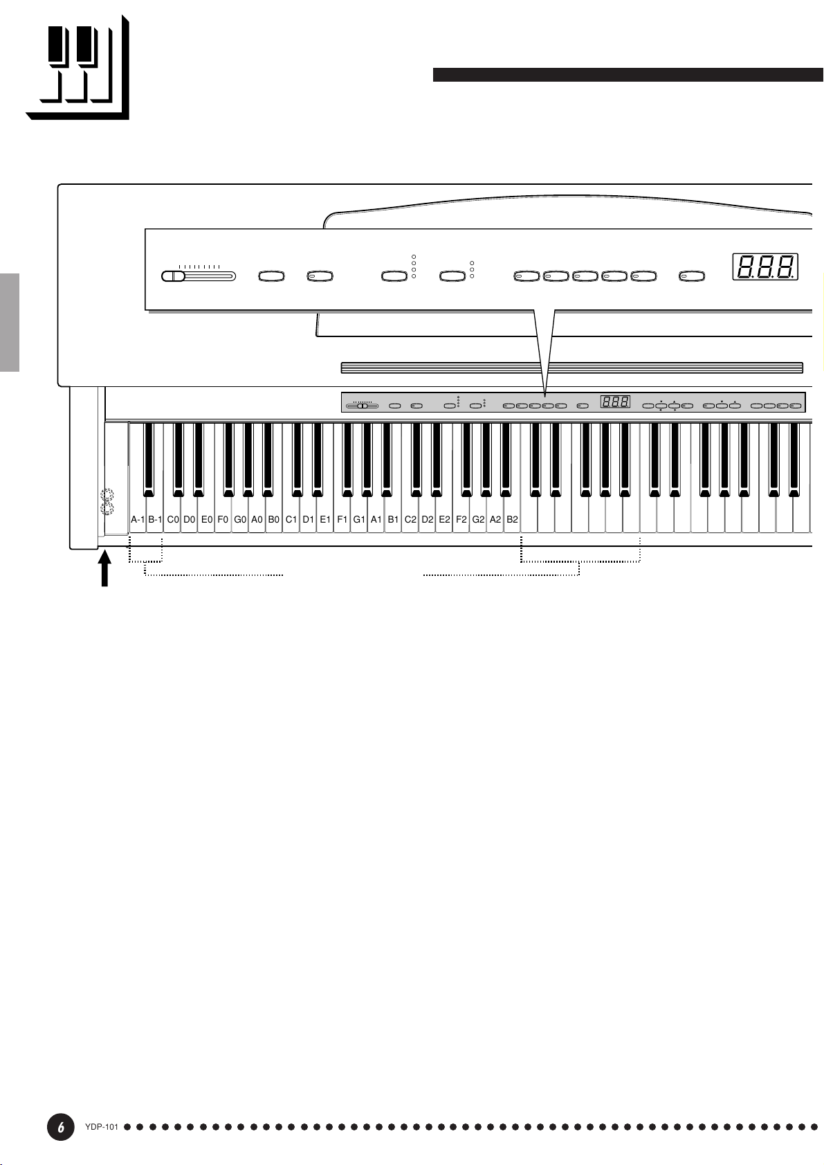
The Control Panel
MASTER VOLUME
MIN
MAX
DEMO
234 56 7
PHONES Jacks (Bottom panel) (See page 9)
ROOM
TRANSPOSE
MASTER VOLUME
MAXMIN
C1 D1 E1 F1 G1 A1 B1 C2 D2 E2 F2 G2 A2 B2 C3 D3 E3 F3 G3 A3 B3 C4 D4 E4 F4 G4 A4 B4 C5 D5 E5
B0A0G0F0E0D0C0B-1A-1
REVERB
HALL1
HALL2
STAGE
TOUCH
ROOM
HALL 1
TOUCHREVERBTRANSPOSEDEMO
HALL 2
STAGE
HARD
MEDIUM
SOFT
GRAND
PIANO
HARPSI-
GRAND
HARD
E. PIANO
CHORD
PIANO
MEDIUM
SOFT
E.PIANO
STRINGS
HARPSI-
CHORD
PIPE
VARIATION
ORGAN
STRINGS
PIPE
ORGAN
VARIATION
METRO-
NOME
FUNCTION
SONG
STOP REC
SELECT
SONGFUNCTIONTEMPO
–
/
NO+/
YES
Tuning keys (See page 19)
TRACKSTART/
2
1
1 [POWER] Switch
Press the [POWER] switch once to turn the
power ON, a second time to turn the power OFF.
When the power is initially turned ON, a voice
selector LED will light, and the power indicator
located below the left end of the keyboard will light.
2 [MASTER VOLUME] Control
The [MASTER VOLUME] control adjusts the
volume (level) of sound produced by the YDP-101’s
internal stereo sound system. The [MASTER
VOLUME] control also adjusts headphone volume
when a pair of headphones is plugged into the
PHONES jack (page 9).
3 [DEMO] Button
Activates the demo playback mode in which you
can select playback of different demonstration
sequences for each of the YDP-101’s voices. See
page 11 for details.
4 [TRANSPOSE] Button
The [TRANSPOSE] button allows access to the
YDP-101’s TRANSPOSE function (to shift the pitch
of the entire keyboard up or down in semitone
intervals).
5 [REVERB] Button
The [REVERB] button selects a number of
digital reverb effects that you can use for extra depth
and expressive power. See page 16 for details.
6 [TOUCH] Button
The [TOUCH] button makes it easy to adjust the
touch response of the YDP-101 to match your
playing style. See page 18 for details.
7 Voice Selectors & [VARIATION] Button
Simply press any of the voice selectors to select
the corresponding voice. The voice selector LED
will light to indicate which voice is currently selected. Press the [VARIATION] button so that its
indicator lights to select a variation of the currently
selected voice.
YDP-101
6
○○○○○○○○○○○○○○○○○○○○○○○○○○○○○○○○○○○○○○○○○○○○○○○○○○○○○○○○
4
Page 7
METRO-
NOME
TEMPO
FUNCTION
FUNCTION
SONG
SONG
SELECT
–
+
/
NO
/
YES
STOP
/
REC
TRACK
12
START
890 !@ # $
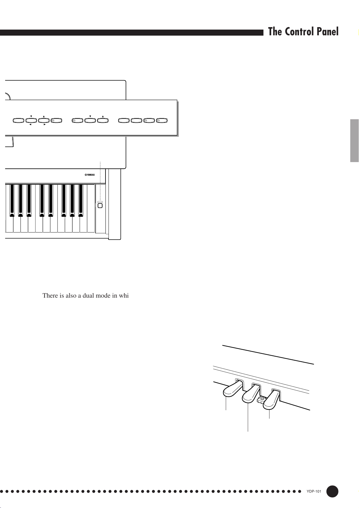
The Control Panel
0 [FUNCTION] Button
This button accesses a range of utility functions
— including the MIDI functions — that significantly
enhance versatility and playability. See page 24 for
details.
! [SONG] Button
This button enters the Piano Song Mode. While
in this mode you can use the [SONG SELECT ▼/
▲] buttons to select from 50 songs.
F5 G5 A5 B5 C6
can be played simultaneously across the full range of
the keyboard (see page 15 for details).
8 [METRONOME] Button
[TEMPO ▼/▲] buttons, below, are used to set the
tempo of the metronome sound. The [–/NO] and [+/
YES] buttons are used to change the time signature
(beat) of the metronome if used while the [METRO-
NOME] button is held — page 20.
1
DIGITAL PIANO YDP-101
POWER
D6 E6 F6 G6 A6 B6 C7
There is also a dual mode in which two voices
Turns the metronome sound on and off. The
@ [SONG SELECT ▼/▲] (–/NO, +/YES) Buttons
These buttons select a piano song number for
playback, and are also used to adjust a range of other
parameters (i.e. their “–/NO” and “+/YES” functions).
# [START/STOP] and [REC] Buttons
These buttons control the YDP-101’s recorder,
letting you record and play back just about anything
you play on the keyboard.
$ TRACK [1] and [2] Buttons
The YDP-101 has a 2-track recorder, and these
buttons are used to select the track(s) to be recorded
or played back. See page 21 for details.
% Pedals
The soft (left), sostenuto (center) and damper
(right) pedals provide a range of expressive control
capabilities similar to the pedal functions on an
acoustic piano. The left pedal can also be assigned to
the song start/stop operation. See page 17 for details.
%
9 [TEMPO ▼/▲] (FUNCTION </>) Buttons
These buttons adjust the tempo of the metronome
function as well as the playback tempo of the recorder function. The tempo range is from 32 to 280
beats per minute — page 20. These same buttons are
also used to select functions — page 24.
○○○○○○○○○○○○○○○○○○○○○○○○○○○○○○○○○○○○○○○○○○○○○○○○○○○○○○○○
5
Soft pedal
Damper pedal
Sostenuto pedal
YDP-101
7
Page 8
Key Cover & Music Stand
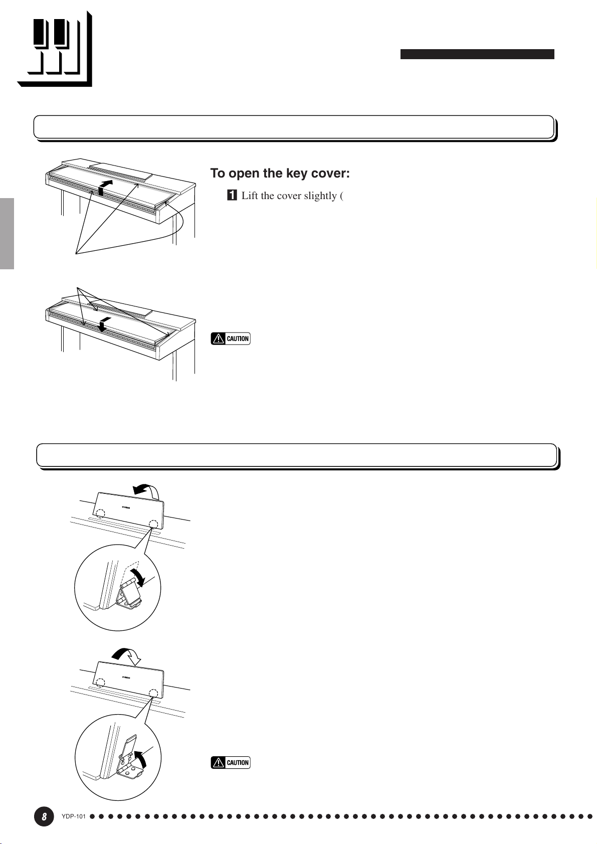
Key Cover
To open the key cover:
ZLift the cover slightly (not too much).
XSlide the cover open.
Be careful to avoid catching your
fingers when opening or closing
the cover.
To close the key cover:
ZSlide the cover toward you.
XGently lower the cover over the keys.
• Hold the cover with both hands when moving it, and do not release it until
it is fully opened or closed. Be careful to avoid catching fingers (yours or
others) between the cover and main unit.
• Do not place objects on top of the key cover. Small objects placed on the
key cover may fall inside the main unit when the cover is opened and may
not be able to be removed. This could cause electric shock, short circuit,
fire or other serious damage to the instrument.
Music Stand
To raise the music stand:
ZPull the stand up and toward yourself as far as it will go.
XFlip down the two metal supports at the left and the right on the rear of
the music stand.
CLower the music stand so that it rests on the metal supports.
To lower the music stand:
ZPull the music stand toward yourself as far as it will go.
XRaise the two metal supports (at the rear of the stand).
CGently lower the music stand backward until it is all the way down.
YDP-101
8
○○○○○○○○○○○○○○○○○○○○○○○○○○○○○○○○○○○○○○○○○○○○○○○○○○○○○○○○
• Do not try to use the music stand in a half-raised position.
When lowering the stand, do not release your hands from the music stand
until it is all the way down.
6
Page 9
Connections
AUX OUT
RL
/
L+R
123
PEDAL
MIDI
IN OUT
AUX OUT
RL/L+R
Stereo System
MIDI
IN OUT
Sequencer
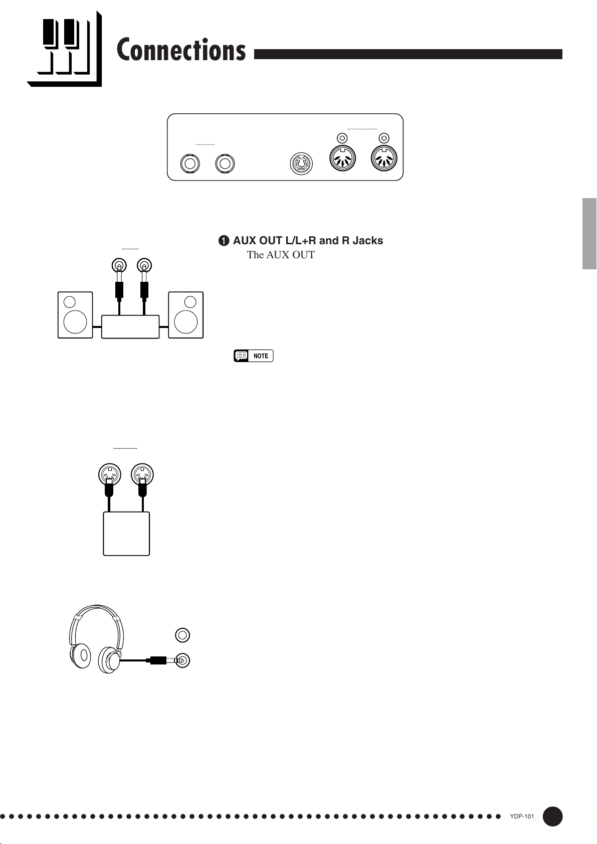
1 AUX OUT L/L+R and R Jacks
The AUX OUT L/L+R and R jacks deliver the output of the YDP-101
for connection to an instrument amplifier, mixing console, PA system, or
recording equipment. If you will be connecting the YDP-101 to a monaural sound system, use only the L/L+R jack. When a plug is inserted into
the L/L+R jack only, the left- and right-channel signals are combined and
delivered via the L/L+R jack so you don’t lose any of the YDP-101’s
sound.
• The AUX OUT jack signal is not controlled by the YDP-101’s volume control.
Use the volume control on the external audio equipment to adjust the level.
2 PEDAL Jack
This terminal is for connecting the pedal cord from the pedal box (refer
to the “Keyboard Stand Assembly” on pages 40-45).
3 MIDI IN and OUT Connectors
The MIDI IN connector receives MIDI data from an external MIDI
device (such as a sequencer or MIDI instrument) which can be used to
control the YDP-101. The MIDI OUT connector transmits MIDI data
generated by the YDP-101 (e.g. note and velocity data produced by
playing the YDP-101 keyboard).
More details on MIDI are given in “MIDI Functions” on page 28.
● PHONES Jacks
(Bottom Panel)
Two sets of standard stereo headphones can be plugged in here for
private practice or late-night playing. The internal speaker system is
automatically shut off when a pair of headphones is plugged into either of
the PHONES jacks.
○○○○○○○○○○○○○○○○○○○○○○○○○○○○○○○○○○○○○○○○○○○○○○○○○○○○○○○○
7
YDP-101
9
Page 10
Selecting & Playing Voices
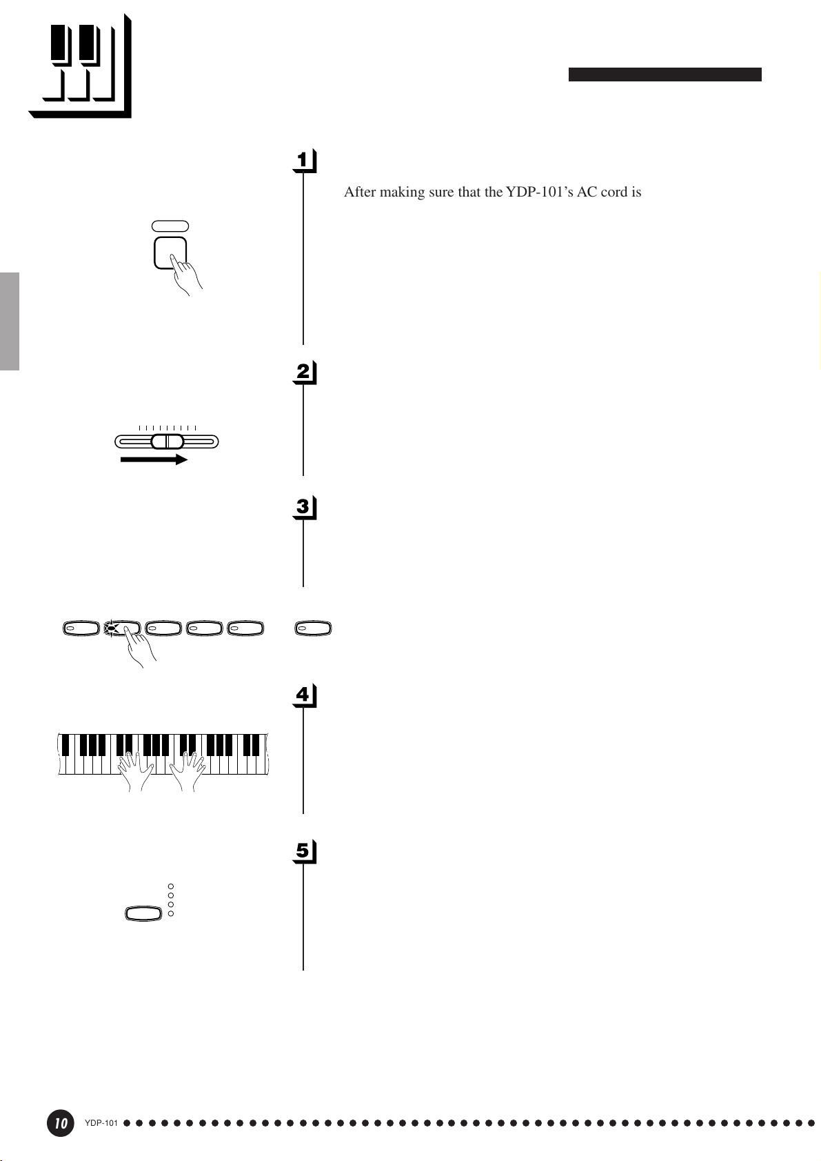
Turn Power On...................................................................................................
After making sure that the YDP-101’s AC cord is properly plugged
POWER
MASTER VOLUME
MIN
MAX
into the YDP-101 itself and plugged into a convenient AC wall outlet,
press the [POWER] switch located to the right of the keyboard to turn
the power ON. In some areas a plug adaptor may be provided to match
the pin configuration of the AC wall outlets in your area.
When the power is turned ON, one of the voice selector LEDs will
light, and the power indicator located below the left end of the keyboard
will light.
Set the Volume ..................................................................................................
Initially set the [MASTER VOLUME] control about half way
between the “MIN” and “MAX” settings. Then, when you start playing,
re-adjust the [MASTER VOLUME] control for the most comfortable
listening level.
GRAND
PIANO
E.PIANO
REVERB
HARPSI-
CHORD
ROOM
HALL1
HALL2
STAGE
STRINGS
PIPE
ORGAN
Select a Voice .....................................................................................................
Select the desired voice by pressing one of the voice selectors. Use
the [VARIATION] button to select a variation of the current voice, as
required.
VARIATION
Play................................................................................................................................
The YDP-101 also offers keyboard touch response, so the volume
and timbre of notes played can be controlled according to how “hard”
you play the keys. The amount of variation available depends on the
selected voice.
Add Reverb As Required.......................................................................
You can add or change reverb as desired by using the [REVERB]
button (page 16).
10
YDP-101
○○○○○○○○○○○○○○○○○○○○○○○○○○○○○○○○○○○○○○○○○○○○○○○○○○○○○○○○
8
Page 11

Playing the Demonstration Tunes
Demonstration tunes are provided that effectively demonstrate each of the
YDP-101’s voices. There are also 50 piano songs that you can play individually,
all in sequence, or in random order. Here’s how you can select and play the
demo tunes.
NOTE
• The demo or piano song mode cannot be engaged while the recorder (page 21) is in use.
• No MIDI reception occurs in the demo/piano song mode.
• The demo/piano song data is not transmitted via the MIDI connectors.
* See page 33 for a complete listing of the demo tunes and piano songs.
Voice Demo
GRAND
PIANO
E.PIANO
DEMO
HARPSI-
CHORD
DEMO
STRINGS
PIPE
ORGAN
Engage the Demo Mode .........................................................................
Press the [DEMO] button to engage the demo mode — the voice
selector indicators will flash in sequence.
Play a Voice Demo.........................................................................................
Press one of the voice selectors to start playback of all songs starting
from the corresponding voice demo tune — featuring the voice normally selected by that voice selector button. (If you press the [START/
STOP] button instead of a voice selector button, the GRAND PIANO
demo tune will begin playback.) The indicator of the selected voice
selector button will flash during playback, and “- - -” will appear on the
LED display. You can start playback of any other voice demo tune
during playback by simply pressing the corresponding voice selector.
You can stop playback at any time by pressing the [START/STOP]
button or the voice selector of the currently playing demo.
NOTE
• Use the [MASTER VOLUME] control to adjust the volume.
Exit From the Demo Mode....................................................................
Press the [DEMO] button to exit from the demo mode and return to
the normal play mode.
○○○○○○○○○○○○○○○○○○○○○○○○○○○○○○○○○○○○○○○○○○○○○○○○○○○○○○○○
9
YDP-101
11
Page 12
Playing the Demonstration Tunes
Piano Song
START
STOP
SONG
/
–
/
NO
SONG
SELECT
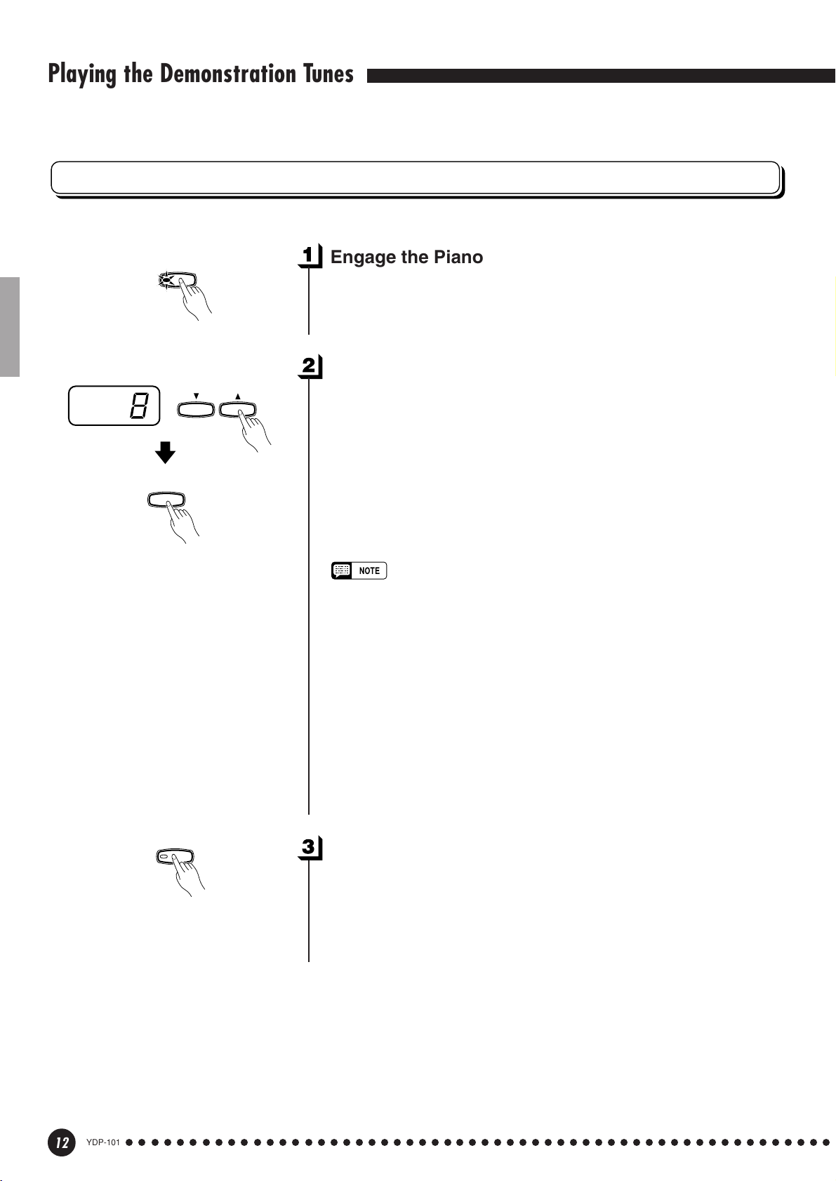
Engage the Piano Song Mode .........................................................
Press the [SONG] button to engage the piano song mode — the
[SONG], [1] and [2] indicators will light.
Play a Piano Song .........................................................................................
To play any of the 50 piano songs provided, use the [SONG SE-
+
/
YES
LECT ▼/▲] buttons to select the number of the tune you want to play
(the number will appear on the LED display), then press the [START/
STOP] button. Playback will stop automatically when playback of the
selected piano song has finished.
Select “ALL” instead of a number to play all piano songs in se-
quence, or select “rnd” to continuously play all piano songs in random order. Press the [START/STOP] button to stop playback.
• Use the [MASTER VOLUME] control to adjust the volume.
▼/▲
• You can use the [TEMPO
required. This produces a relative tempo variation, with a range from “-50”
through “- - -” to “50” at maximum; the range will differ depending on the
selected song.
• The default tempo “- - -” is automatically selected whenever a new piano
song is selected, or playback of a new piano song begins during “
“
rnd
” playback.
• You can play the keyboard along with the piano song playback. The voice
playing on the keyboard can be changed.
• You can change the Reverb type that is applied to the voice you play on
the keyboard and for the piano song playback. You can change the Touch
sensitivity that is applied to the voice you play on the keyboard. When a
new piano song is selected or a new piano song is automatically started
in continuous play, the HALL 1 reverb type will automatically be selected.
] buttons to adjust the playback tempo as
ALL
” or
SONG
12
YDP-101
○○○○○○○○○○○○○○○○○○○○○○○○○○○○○○○○○○○○○○○○○○○○○○○○○○○○○○○○
Exit From the Piano Song Mode....................................................
Press the [SONG] button to exit from the piano song mode, the
indicator will go off, and return to the normal play mode.
10
Page 13
Playing the Demonstration Tunes
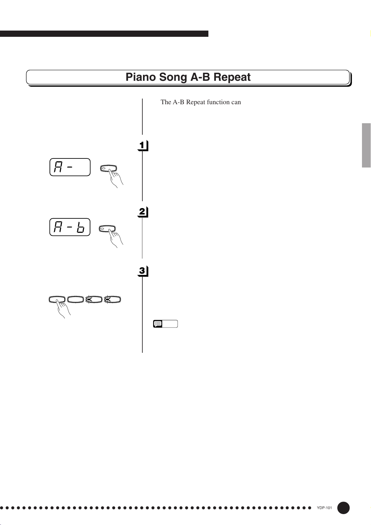
Piano Song A-B Repeat
The A-B Repeat function can be used to continuously repeat a
specified phrase within a piano song. Combined with the Part Cancel
function described below, this provides an excellent way to practice
difficult phrases.
Specify the Beginning (A) of the Phrase..............................
START
STOP
FUNCTION
Select and play a piano song, then press the [FUNCTION] button at
the beginning of the phrase you want to repeat. This sets the “A” point
(“A-” will appear on the display).
To set the “A” point at the very beginning of the song, press the
[FUNCTION] button before starting playback.
Specify the End (B) of the Phrase ...............................................
FUNCTION
Press the [FUNCTION] button a second time at the end of the
phrase. This sets the “B” point (“A-b” will appear on the display). At
this point repeat playback will begin between the specified A and B
points.
Stop Playback....................................................................................................
/
REC
TRACK
12
Press the [START/STOP] button to stop playback while retaining
the specified A and B points. A-B repeat playback will resume if the
[START/STOP] button is then pressed again.
To cancel the A and B points press the [FUNCTION] button once.
NOTE
• The A and B points are automatically canceled when a new song is
selected.
• The A-B Repeat function cannot be used during “
ALL
” or “
rnd
” playback.
○○○○○○○○○○○○○○○○○○○○○○○○○○○○○○○○○○○○○○○○○○○○○○○○○○○○○○○○
11
YDP-101
13
Page 14
Playing the Demonstration Tunes
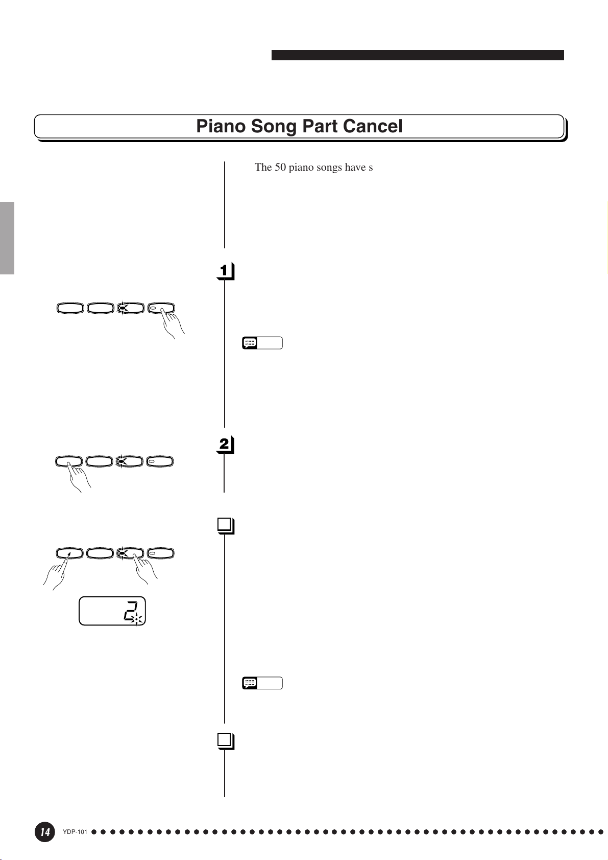
Piano Song Part Cancel
be turned on and off as required so you can practice the corresponding
part on the keyboard. The right-hand part is played by the recorder’s [1]
track, and the left-hand part is played by recorder’s [2] track. (Some of
the songs are arrangements for four-hands, tracks [1] and [2] correspond to primo and secondo parts of the arrangement.)
Turn the Desired Part Off.......................................................................
START
STOP
/
REC
TRACK
12
— the corresponding indicator will go out (these buttons alternately
toggle the corresponding part on and off).
The 50 piano songs have separate left- and right-hand parts that can
Press the TRACK [1] or [2] button to turn the corresponding part off
NOTE
• The parts can be turned on or off even during playback.
ALL
• The Piano Song Part Cancel function cannot be used during “
“
rnd
” playback.
• The “Piano Song Part Cancel Volume” function described on page 27 can
be used to set the canceled part so that it plays at a volume from “0” (no
sound) to “20”. The default setting is “5”.
• Both parts are automatically turned ON whenever a new song is selected.
” or
START
STOP
START
STOP
/
REC
TRACK
12
Start/Stop Playback.....................................................................................
Press the [START/STOP] button to start and stop playback as
required.
Synchro Start .....................................................................................................
/
REC
TRACK
12
When the Synchro Start function is engaged, playback of the selected piano song will begin automatically as soon as you start playing
on the keyboard.
To engage the Synchro Start function press the [START/STOP]
button while holding the part button corresponding to the part which is
ON. A dot will appear in the lower right corner of the display. (Repeat
the previous operation to disengage the Syncro Start function.)
Playback will then start as soon as you begin playing on the keyboard.
NOTE
• If you hold a track button which is OFF while pressing the [START/STOP]
button, that track will be turned ON and the Synchro Start mode will be
engaged.
14
YDP-101
○○○○○○○○○○○○○○○○○○○○○○○○○○○○○○○○○○○○○○○○○○○○○○○○○○○○○○○○
Left Pedal Start/Stop ..................................................................................
The left pedal can be assigned to start and stop piano song playback
via the “Left Pedal Mode” function described on page 27.
12
Page 15
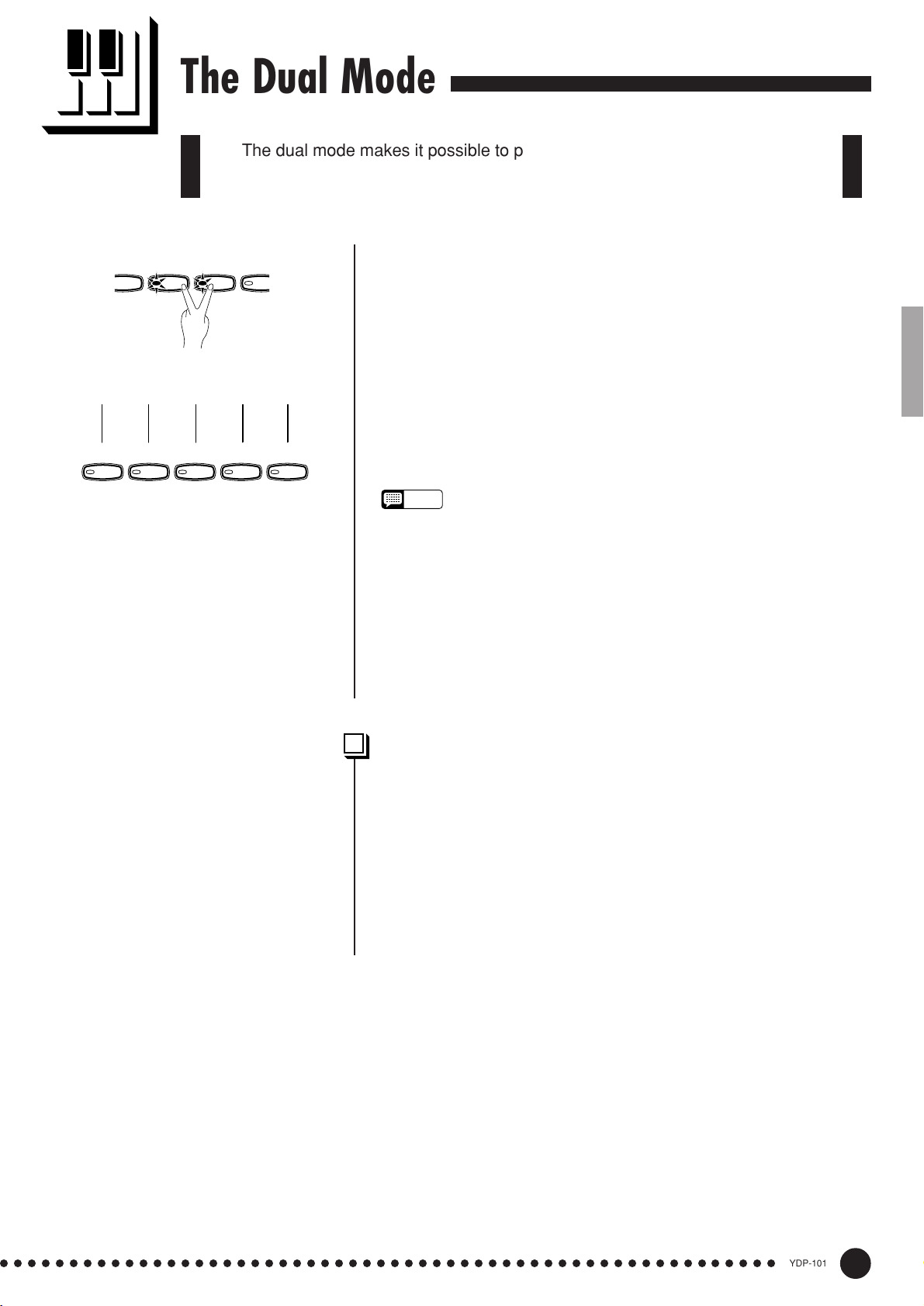
The Dual Mode
P
E
A
The dual mode makes it possible to play two voices simultaneously across
the entire range of the keyboard.
HARPSI-
IANO
Voice numbering priority
CHORD
STRINGS
1 2 3 4 5
GRAND
PIANO
E.PIANO
HARPSI-
CHORD
STRINGS
PIP
ORG
PIPE
ORGAN
To activate the dual mode simply press two voice selectors at the
same time (or press one voice selector while holding another). The
voice indicators of both selected voices will light when the dual mode is
active. To return to the normal single-voice play mode, press any single
voice selector.
According to the voice numbering priority as shown in the diagram
on the left, lower valued voice numbers will be designated as the 1st
Voice (the other voice will be designated as the 2nd Voice).
The [STRINGS] [VARIATION] voice has a slow attack. This
voice can sometimes be used with another voice in the Dual Mode to
produce a better “blend”.
NOTE
• The [VARIATION] button indicator will light if the variation is engaged for
either or both of the dual-mode voices. While the dual mode is engaged
the [VARIATION] button can be used to turn the variation for both voices
on or off. To use the variation for only one of the voices the setting must
be made prior to engaging the dual mode.
• [REVERB] in the Dual Mode
The reverb type assigned to the 1st Voice will take priority over the other.
(If the reverb is set to OFF, the 2nd Voice’s reverb type will be in affect.)
Reverb depth setting via the panel controls (i.e. pressing the [-/NO] or [+/
YES] buttons while holding the [REVERB] button — see page 16) will be
applied to the 1st Voice only.
Other Dual Mode Functions ...............................................................
The YDP-101 Function mode provides access to a number of other
dual-mode functions, listed below. See the corresponding pages for
details.
• Dual Balance ................................................. 26
• Dual Detune .................................................. 26
• 1st Voice Octave Shift ................................... 26
• 2nd Voice Octave Shift .................................. 26
• Reset ............................................................. 26
○○○○○○○○○○○○○○○○○○○○○○○○○○○○○○○○○○○○○○○○○○○○○○○○○○○○○○○○
13
YDP-101
15
Page 16

Reverb
The [REVERB] button selects a number of digital reverb effects that you can
use for extra depth and expressive power.
REVERB
ROOM
HALL1
HALL2
STAGE
To select a reverb type press the [REVERB] button a few times until
the indicator corresponding to the desired type lights (the indicators
light in sequence each time the [REVERB] button is pressed). No
reverb is produced when all indicators are off.
OFF
No reverb effect is selected when no REVERB indicator is lit.
ROOM
This setting add a continuous reverb effect to the sound that is similar
to the type of acoustic reverberation you would hear in a room.
HALL 1
For a “bigger” reverb sound, use the HALL 1 setting. This effect
simulates the natural reverberation of a small-size concert hall.
HALL 2
For a really spacious reverb sound, use the HALL 2 setting. This effect
simulates the natural reverberation of a large concert hall.
STAGE
A simulation of the type of reverb produced in a stage environment.
NOTE
• The default reverb type (including OFF) and depth settings are different
for each voice.
REVERB
ROOM
HALL1
HALL2
STAGE
–
/
NO
SONG
SELECT
Adjusting Reverb Depth .........................................................................
Adjust the reverb depth for the selected voice by using the [–/NO]
+
/
YES
and [+/YES] buttons while holding the [REVERB] button. The depth
range is from 0 through 20 (the current depth setting appears on the
LED display while the [REVERB] button is held). A setting of “0”
produces no effect, while a setting of “20” produces maximum reverb
depth. Press the [–/NO] and [+/YES] buttons simultaneously while
holding the [REVERB] button to recall the default setting for the
current voice (default depth settings are different for each voice).
16
YDP-101
○○○○○○○○○○○○○○○○○○○○○○○○○○○○○○○○○○○○○○○○○○○○○○○○○○○○○○○○
14
Page 17

The Pedals
The YDP-101 has three foot pedals that produce a range of expressive
effects similar to those produced by the pedals on an acoustic piano.
Damper (Right) Pedal ................................................................................
The damper pedal functions in the same way as a damper pedal on
an acoustic piano. When the damper pedal is pressed notes played have
a long sustain. Releasing the pedal immediately stops (damps) any
sustained notes.
Soft pedal
Sostenuto pedal
Damper pedal
Sostenuto (Center) Pedal ......................................................................
If you play a note or chord on the keyboard and press the sostenuto
pedal while the note(s) are held, those notes will be sustained as long as
the pedal is held (as if the damper pedal had been pressed) but all
subsequently played notes will not be sustained. This makes it possible
to sustain a chord, for example, while other notes are played “staccato.”
NOTE
• Organ and string voices will continue to sound for as long as the sostenuto pedal is depressed.
Soft (Left) Pedal ...............................................................................................
The soft pedal reduces the volume and slightly changes the timbre of
notes played while the pedal is pressed. The soft pedal will not affect
notes which are already playing when it is pressed.
The left pedal can also be assigned to the song start/stop operation
via the “Left Pedal Mode” described on page 27.
○○○○○○○○○○○○○○○○○○○○○○○○○○○○○○○○○○○○○○○○○○○○○○○○○○○○○○○○
15
YDP-101
17
Page 18
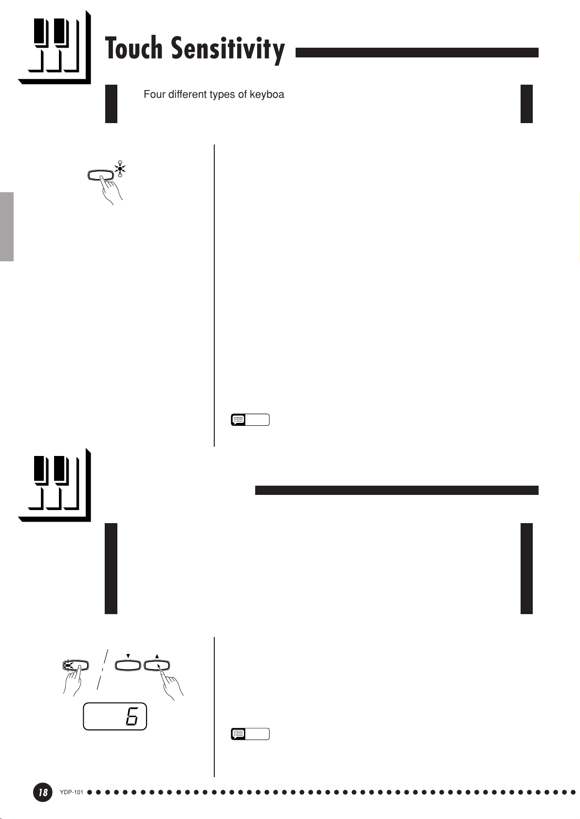
Touch Sensitivity
Four different types of keyboard touch sensitivity — HARD, MEDIUM, SOFT
or FIXED — can be selected to match different playing styles and preferences.
To select a touch sensitivity type press the [TOUCH] button a few
TOUCH
HARD
MEDIUM
SOFT
times until the indicator corresponding to the desired type lights (the
indicators light in sequence each time the [TOUCH] button is pressed).
HARD
The HARD setting requires the keys to be played quite hard to
produce maximum loudness.
MEDIUM
The MEDIUM setting produces a fairly “standard” keyboard response.
This is the initial factory default setting.
SOFT
The SOFT setting allows maximum loudness to be produced with
relatively light key pressure.
FIXED (no indicator lit)
All notes are produced at the same volume no matter how hard the
keyboard is played.
When the FIXED type is selected, the volume of notes played in the
FIXED mode can be set by using the [–/NO] and [+/YES] buttons while
the [TOUCH] button is held (the current volume level appears on the
display). The volume range is from 1 through 127. The default setting
is 64.
TRANSPOSE
NOTE
• This setting does not change the weight of the keyboard.
• The touch sensitivity type and volume set in the FIXED mode will become
the common setting for all voices.
Transposition
The YDP-101’s TRANSPOSE function makes it possible to shift the pitch of
the entire keyboard up or down in semitone intervals up to a maximum of 12
semitones (i.e. a maximum of one octave up or down). “Transposing” the pitch of
the YDP-101 keyboard facilitates playing in difficult key signatures, and you can
easily match the pitch of the keyboard to the range of a singer or other instrumentalist.
Use the [–/NO] or [+/YES] button while holding the [TRANS-
POSE] button to transpose down or up as required. The transposition
range is from “–12” (down one octave) through “0” (normal pitch) to
“12” (up one octave). The amount of transposition appears on the LED
display while the [TRANSPOSE] button is held. The default transpose
setting is “0”.
–
/
NO
SONG
SELECT
+
/
YES
18
YDP-101
○○○○○○○○○○○○○○○○○○○○○○○○○○○○○○○○○○○○○○○○○○○○○○○○○○○○○○○○
NOTE
• The [TRANSPOSE] button indicator remains lit when a transpose setting
other than “0” is selected.
• Notes below and above the A-1 … C7 range of the YDP-101 sound one
octave higher and lower, respectively.
16
Page 19
Tuning
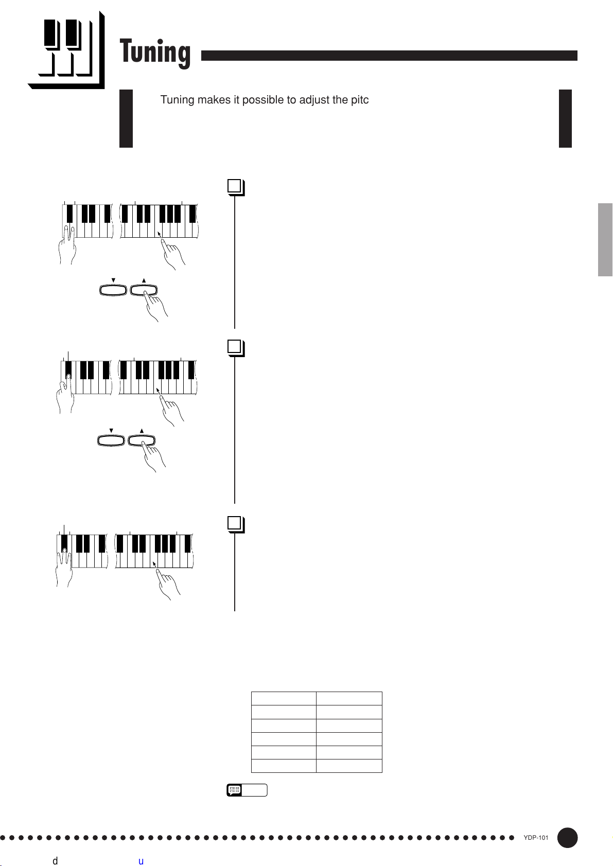
Tuning makes it possible to adjust the pitch of the YDP-101 over a 427.0 Hz
… 453.0 Hz (corresponding to the A3 note’s Hz) range in approximately 0.2
Hertz intervals. Pitch control is useful for tuning the YDP-101 to match other
instruments or recorded music.
A-1B
-1
A
A#
-1
3
C
3
B
Tuning Up ...............................................................................................................
Z To tune up (raise pitch), hold the A-1 and B-1 keys simultaneously.
X Press any key between C3 and B3. Each time a key in this range is
pressed the pitch is increased by approximately 0.2 Hz.
The [–/NO] and [+/YES] buttons can also be used to tune down or up,
–
/
NO
SONG
SELECT
respectively, in
approximately
[–/NO] and [+/YES] buttons simultaneously to recall standard tuning
+
/
YES
(A3 = 440 Hz).
1 Hz
decrements/
increments. Press the
C Release the A-1 and B-1 keys.
-1
3
C
3
B
Tuning Down .......................................................................................................
Z To tune down (lower pitch), hold the A-1 and A#-1 keys simulta-
neously.
X Press any key between C3 and B3. Each time a key in this range is
pressed the pitch is decreased by approximately 0.2 Hz.
The [–/NO] and [+/YES] buttons can also be used to tune down or up,
respectively, in
approximately
1 Hz
decrements/
increments. Press the
[–/NO] and [+/YES] buttons simultaneously to recall standard tuning
(A3 = 440 Hz).
–
/
NO
SONG
SELECT
+
/
YES
A#
A-1B
C Release the A-1 and A#-1 keys.
-1
-1
3
C
3
B
To Restore Standard Pitch ...................................................................
Z To restore the default pitch (A3 = 440 Hz), hold the A-1, A#-1 and
B-1 keys simultaneously.
X Press any key between C3 and B3.
C Release the A-1, A#-1 and B-1 keys.
In terms of “Hertz”, the overall tuning range is from 427.0 Hz to 453.0
Hz. The current tuning setting is shown on the LED display while the tuning
is being adjusted. Tenths of a Hertz are indicated on the LED display by the
appearance and position of one or two dots, as in the following example:
Display Value
440 440.0
4.40 440.2
44.0 440.4
440. 440.6
4.40. 440.8
NOTE
• An alternative tuning method is available in the Function mode — page 25.
○○○○○○○○○○○○○○○○○○○○○○○○○○○○○○○○○○○○○○○○○○○○○○○○○○○○○○○○
17
YDP-101
19
Page 20

The Metronome & Tempo Control
The YDP-101 built-in metronome is a convenient feature for practice, and it
can also provide a solid rhythmic guide when recording using the Recorder
feature, described in the next section.
The Metronome
METRO-
NOME
Beat indicator
–
/
NO
METRO-
SONG
SELECT
NOME
+
/
YES
The metronome sound is alternately turned on and off by pressing
the [METRONOME] button. When on, the beat indicator flashes at the
current tempo.
Metronome Time Signature.................................................................
The time signature (beat) of the metronome can be set by using the
[–/NO] and [+/YES] buttons while holding the [METRONOME]
button. You can set the beat to 0, 2, 3, 4 or 6 (the current setting appears
on the LED display while the [METRONOME] button is held). Press
the [–/NO] and [+/YES] buttons simultaneously while holding the
[METRONOME] button to recall the default setting “0” (no accent).
Metronome Volume Function ............................................................
The volume of the metronome sound can be adjusted via the Metronome Volume function in the Function mode—page 27.
Tempo Control
TEMPO
FUNCTION
YDP-101
20
○○○○○○○○○○○○○○○○○○○○○○○○○○○○○○○○○○○○○○○○○○○○○○○○○○○○○○○○
The tempo of the metronome and recorder playback (the recorder is
described in the next section) can be set from 32 to 280 beats per
minute by using the [TEMPO t/s] buttons. The selected tempo will
appear on the LED display while in the normal play mode and while the
[TEMPO t/s] buttons are being used to adjust the tempo in the
recording/playback mode. The default tempo (120 or the recorded song
tempo when the recorder contains data and the playback track indicator
is lit) can be recalled by simultaneously pressing the [t] and [s]
buttons.
18
Page 21

Using the Recorder
The YDP-101 features a two-track recorder that let you record what you play
on the keyboard and then play it back. Two tracks mean that you can “overdub”
one part on top of another, using a different voice if you like. The recorder feature
is a useful adjunct to any keyboard study program, since it lets you hear exactly
how you sound from the listener’s perspective. It can also be just plain fun.
The recorder actually records the following data:
■ Entire Song
● Tempo ● Time signature (beat) ● Reverb type (including OFF)
■ Individual Tracks
● Notes played ● Voice selection ● Voice variation
● Dual mode voices ● Damper pedal ● Soft pedal
● Sostenuto pedal (not recorded as an initial setting)
● Reverb depth ● Dual balance (F3) ● Dual detune (F3)
● Dual octave shift (F3)
Recording
GRAND
PIANO
START
STOP
STOP
E.PIANO
/
/
REC
REC
HARPSI-
STRINGS
CHORD
TRACK
12
TRACKSTART
12
PIPE
ORGAN
Make All Necessary Initial Settings ...........................................
Before actually beginning to record, select the voice you want to
record with (or voices if you will be using the dual mode). You might
also want to set the volume and tempo controls.
Engage the Record Ready Mode ..................................................
Press the [REC] button to engage the record ready mode (recording
does not actually start yet). The record ready mode can be disengaged
before recording by pressing the [REC] button a second time.
• The record ready mode cannot be engaged while the demo/piano song
mode is engaged.
Select the Record Track ..........................................................................
When the record mode is engaged in the previous step, the lastrecorded track will automatically be selected for recording and its indicator — i.e. the [1] or [2] button indicator — will glow red. If you want to
record on a different track, press the appropriate track button so that its
indicator glows red.
• The track button indicators of tracks which contain previously recorded data
will glow green (unless the track is turned off as described below). The
previously-recorded data on the non-record track will normally be played
back as you record, so you can play along with a previously-recorded track.
If you don’t want to hear the previously recorded track as you record (when
you want to record a song different from what you recorded on the previous
track etc.,), press the playback track button before pressing the [REC]
button (step 1, above) so that its indicator goes out.
• Recording on a track which already contains data will erase all previous
data on that track.
• When the record mode is engaged the amount of memory available for
recording will be shown on the LED display in approximate kilobytes
(starting at “25”), and the rightmost dot on the LED display will flash at the
current METRONOME tempo setting.
○○○○○○○○○○○○○○○○○○○○○○○○○○○○○○○○○○○○○○○○○○○○○○○○○○○○○○○○
19
YDP-101
21
Page 22

Using the Recorder
Start Recording................................................................................................
Recording will begin automatically as soon as you play a note on the
keyboard or press the [START/STOP] button. The current measure
number will appear on the display while recording.
START
STOP
START
STOP
START
STOP
/
REC
/
REC
TRACK
12
TRACK
12
Stop Recording ................................................................................................
• The left pedal can be assigned to start and stop recording via the “Left
Pedal Mode” function described on page 27.
• If the metronome was on when you started recording, you’ll be able to
keep time with the metronome while recording, but the metronome sound
will not be recorded.
• You can record up to a maximum of about 5,000 notes, depending on
pedal usage and other factors. The record track indicator will begin to
flash when recorder memory is almost full. If the memory becomes full
during recording, “
automatically. (All recorded data up to that point will be retained.)
FUL
” will appear on the display and recording will stop
Press either the [REC] or [START/STOP] button to stop recording.
The indicator of the recorded track will glow green to indicate that it
now contains data.
Changing the Initial Settings.............................................................
/
REC
TRACK
12
The initial voice, tempo, reverb type, and reverb depth settings made
in step 1 of the recording procedure are actually recorded by the YDP-
101.
These initial settings can be changed after the recording is finished by
pressing the [REC] button to engage the record ready mode, pressing the
appropriate track button, making the required changes, and then pressing
the [REC] button again to exit from the record ready mode and register
the changes.
If you do this, be careful not to press the [START/STOP] button or a
key on the keyboard, either of which will start recording and erase all
previous recorded data on the selected track.
It is possible to cancel the operation even after changes have been
made: change tracks and then press the [REC] button to exit from the
record mode (this also cancels data for the entire song).
TRACKSTART
12
22
STOP
YDP-101
/
REC
Press twice.
○○○○○○○○○○○○○○○○○○○○○○○○○○○○○○○○○○○○○○○○○○○○○○○○○○○○○○○○
• The following data for initial settings cannot be changed: “Dual balance
(F3)”, “Dual detune (F3)” or “Dual octave shift (F3)”.
Erasing a Single Track ..............................................................................
All data can be erased from either of the recorder’s tracks by engaging the record mode, selecting the track you want to erase, and then
pressing the [START/STOP] button twice without recording any data.
20
Page 23
START
STOP
Using the Recorder
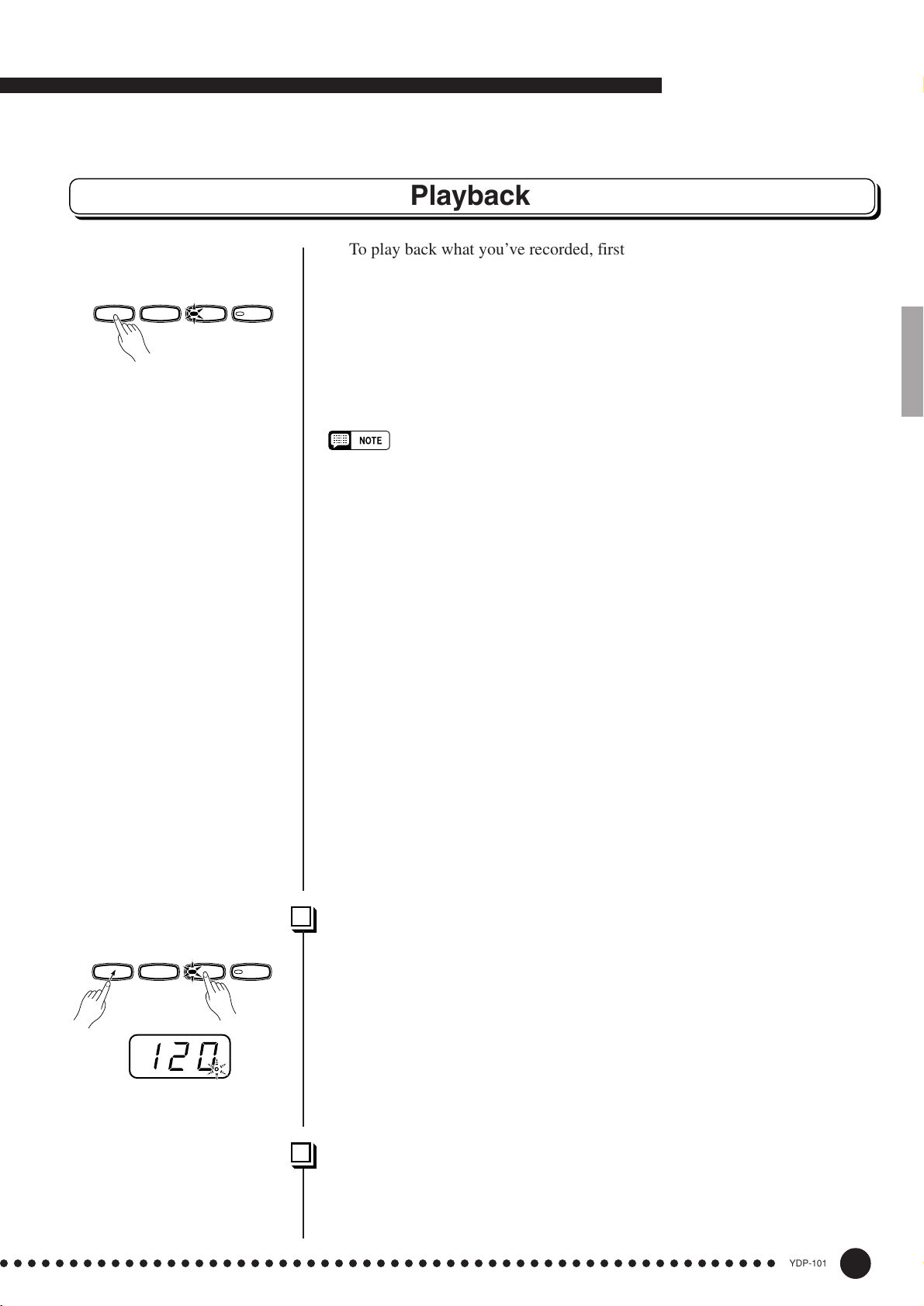
Playback
To play back what you’ve recorded, first make sure that the green track
indicators of the tracks you want to play are lit. If not, press the corresponding
/
REC
TRACK
12
track button(s) so that they are lit. Then press the [START/STOP] button.
Playback starts from the beginning of the recorded data, and will stop automatically at the end of the recorded data. You can also stop playback at any time by
pressing the [START/STOP] button.
To mute a track so that it doesn’t play back, press the corresponding track
button so that its indicator goes out (press again to turn the track back on).
The current measure number appears on the display during playback.
• It is possible to play along on the keyboard during playback. In this case, the
playback voice and the voice you play on the keyboard are not the same. The
playback voice is the voice that was set when the data was recorded. The voice you
play on the keyboard is the voice that is selected on the panel.
• The playback volume and tempo can be adjusted by using the [MASTER VOLUME]
control and [TEMPO
neously to recall the default tempo).
• All recorder data will be retained in memory for about one week after the power is
turned off. If you want to keep your recorded data for longer periods, turn the power
on for a few minutes at least once a week. It is also possible to store it to an
external MIDI storage device by using the Bulk Data Dump function described on
page 30.
• The track indicators will not light automatically when the power is turned on even if
the recorder contains data. It is therefore necessary to press the track buttons so
that the corresponding green indicators light before starting recorder playback. It is
also a good idea to press the track buttons to check if the tracks contain data
before recording. If the green indicator lights when the corresponding track button
is pressed, that track contains data which will be erased and replaced by the newlyrecorded data.
• If the metronome is being used during playback, the metronome will automatically
stop when playback is stopped.
• During recorder playback, the volume of a track which is turned off will always be
“0” (i.e. the “Piano Song Part Cancel Volume” function — page 27 — only affects
piano song playback.
• The playback data is not transmitted via the MIDI OUT connector.
• Playback cannot be started when the demo/piano song mode is engaged.
• Playback cannot be started when the recorder contains no data, or when both track
buttons are off.
• When using REVERB during playback, depending upon the conditions one reverb
type will take priority.
▼/▲
] buttons (press both [TEMPO ▼/▲] buttons simulta-
Synchro Start ....................................................................................................................
START
STOP
/
REC
TRACK
12
When the Synchro Start function is engaged, recorder playback will begin
automatically as soon as you start playing on the keyboard.
To engage the Synchro Start function press the [START/STOP] button
while holding a track button which is ON. The rightmost dot on the display will
flash at the current tempo. (Repeat the previous operation to disengage the
Syncro Start function.) Playback will then start as soon as you begin playing on
the keyboard.
If you hold a track button which is OFF while pressing the [START/STOP]
button, that track will be turned ON and the Synchro Start mode will be engaged.
Left Pedal Start/Stop .................................................................................................
The left pedal can be assigned to start and stop recorder playback via the
“Left Pedal Mode” function described on page 27. This is convenient for starting playback of the recorded part anytime after you have started playing.
○○○○○○○○○○○○○○○○○○○○○○○○○○○○○○○○○○○○○○○○○○○○○○○○○○○○○○○○
21
YDP-101
23
Page 24
The Function Mode
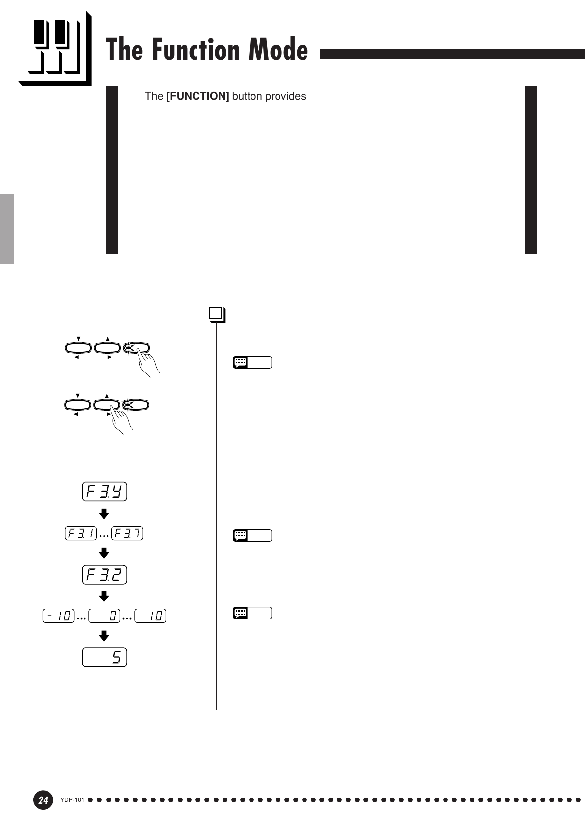
The [FUNCTION] button provides access to a range of functions that give the
YDP-101 extraordinary versatility. The functions are categorized in groups as
follows:
F1 Tuning ....................................................................... 25
F2 Scale ......................................................................... 25
F3 Dual Mode Functions .............................................. 26
F4 Left Pedal Mode ....................................................... 27
F5 Metronome Volume .................................................. 27
F6 Piano Song Part Cancel Volume............................. 27
F7 MIDI Functions......................................................... 28
F8 Backup Functions ................................................... 31
To Select a Function … ...........................................................................
TEMPO
FUNCTION
TEMPO
FUNCTION
FUNCTION
FUNCTION
● Operation Example
Press [+/YES]
Use FUNCTION [<], [>]
Press [–/NO] or [+/YES]
once
Use [–/NO], [+/YES]
(sub-mode)
Z Press the [FUNCTION] button so that its indicator lights.
NOTE
• Functions cannot be selected during demo/piano song playback or when
the recorder is in operation.
X Use the FUNCTION [<] and [>] buttons to select the desired
function.
C In the case of the Scale (F2), Dual Mode (F3), MIDI (F7), and
Backup (F8) functions, you will have to press the [+/YES] button
once to enter the respective sub-mode after the function has been
selected, and then use the FUNCTION [<] and [>] buttons again
to select the desired sub-function.
NOTE
• The Dual mode must be engaged before the F3 function can be selected.
If the Dual mode is not engaged, “
Dual sub-mode will not be available.
F3.-
” will appear on the display and the
V Set the function as required by using the [–/NO] and [+/YES]
buttons (see the individual function descriptions, below).
NOTE
• After selecting the function, the current setting will be displayed when the
[–/NO] or [+/YES] button is pressed for the first time.
B Press the [FUNCTION] button so that its indicator goes out to exit
from the function mode.
24
YDP-101
○○○○○○○○○○○○○○○○○○○○○○○○○○○○○○○○○○○○○○○○○○○○○○○○○○○○○○○○
22
Page 25
The Function Mode
F1
F2
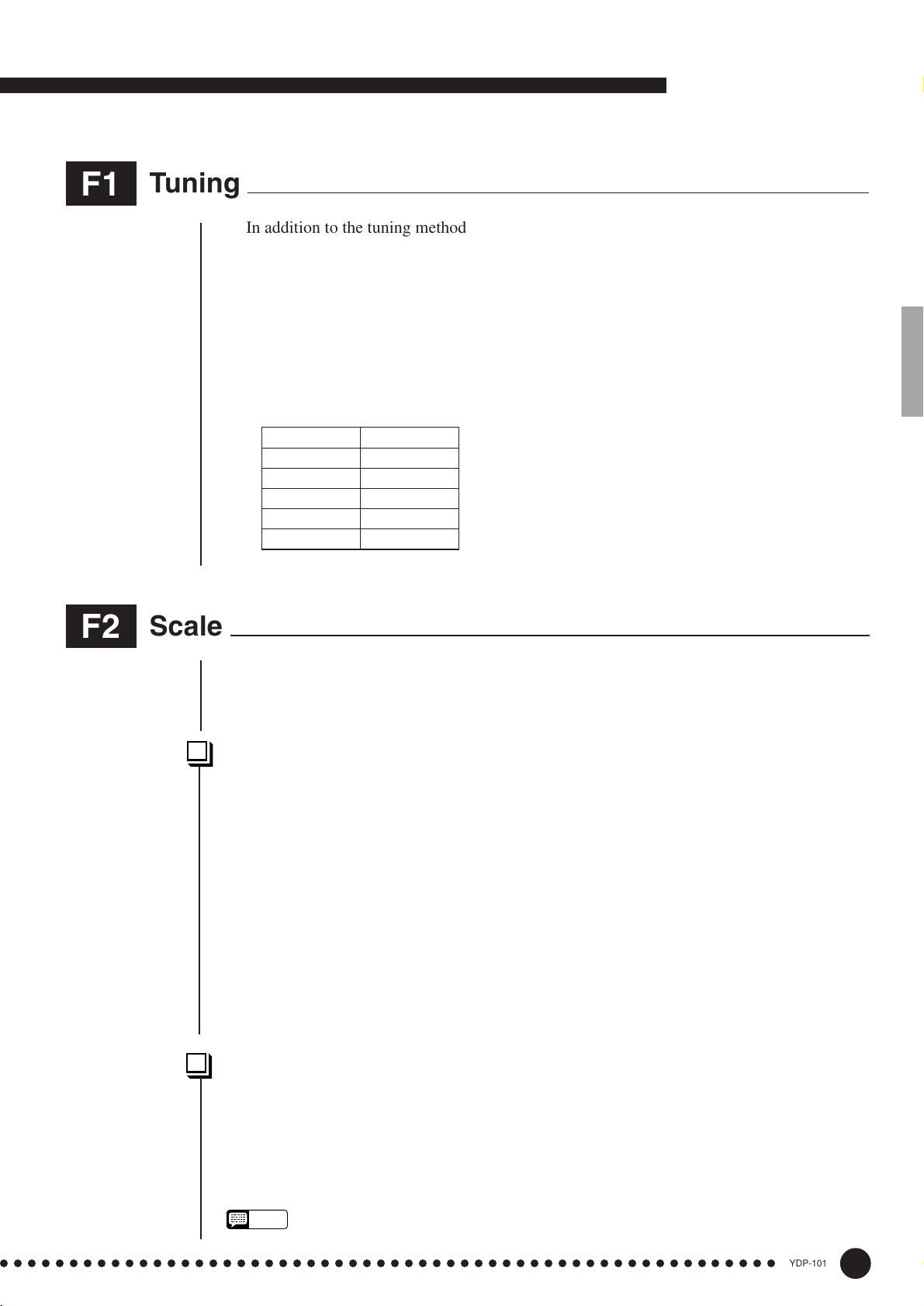
Tuning
In addition to the tuning method described on page 19, overall tuning can also be accom-
plished via the F1 function.
After selecting “F1”, use the [–/NO] and [+/YES] buttons to lower or raise the pitch in
approximately 0.2 Hz increments (the first time the [–/NO] or [+/YES] button is pressed
simply switches to the tuning value display without actually changing the tuning). The overall
tuning range is from 427.0 Hz to 453.0 Hz (corresponding to the A3 note’s Hz). Press the
[–/NO] and [+/YES] buttons simultaneously to recall the default value “440 Hz”.
Tenths of a Hertz are indicated on the LED display by the appearance and position of one
or two dots, as in the following example:
Display Value
440 440.0
4.40 440.2
44.0 440.4
440. 440.6
4.40. 440.8
Scale
After selecting “F2.Y”, press the [+/YES] button to engage the scale function sub-mode,
then use the FUNCTION [<] and [>] buttons to select the desired scale function, as listed
below.
F2.1: Scale ..........................................................................................................................................................
In addition to the standard Equal Temperament tuning, the YDP-101 includes 6 classic
tunings that you can select and use to play music of the corresponding period, or experiment
with in a more modern context. The tunings are:
1: Equal Temperament 5: Mean Tone
2: Pure Major 6: Werckmeister
3: Pure Minor 7: Kirnberger
4: Pythagorean
Use the [–/NO] and [+/YES] buttons to select the number of the desired tuning.
Press the [–/NO] and [+/YES] buttons simultaneously to recall the default settings (Equal
Temperament tuning).
F2.2: Base Note .............................................................................................................................................
Unlike Equal Temperament tuning, these classic tunings must be tuned to a specific key.
Use the [–/NO] and [+/YES] buttons to select the key you want the previously selected tuning
to be based. The selected key will appear on the display, followed by a low bar if flat (e.g.
“A_”) or a high bar if sharp (e.g. “F~”).
Press the [–/NO] and [+/YES] buttons simultaneously to recall the default settings “C”.
• The base note setting is effective for tunings other than the Equal Temperament tuning.
NOTE
○○○○○○○○○○○○○○○○○○○○○○○○○○○○○○○○○○○○○○○○○○○○○○○○○○○○○○○○
23
YDP-101
25
Page 26

The Function Mode
F3
Dual Mode Functions
After selecting “F3.Y”, press the [+/YES] button to engage the dual-mode function sub-
mode, then use the FUNCTION [<] and [>] buttons to select the desired dual mode func-
tion, as listed below.
If the Dual mode is not engaged “F3.-” will appear instead of “F3.Y” and the Dual mode
functions cannot be selected. If this happens engage the Dual mode and proceed.
■ SHORTCUT: You can jump directly to the dual-mode functions (F3) by pressing the
[FUNCTION] button while holding the two dual-mode voice selectors.
NOTE
• Dual mode function settings are set individually for each voice combination.
F3.1: Dual Balance.....................................................................................................................................
The volume levels of the two voices combined in the dual mode can be adjusted as required by using this function. Use the [–/NO] and [+/YES] buttons to adjust the balance as
required. The balance range is from 0 through 20. A setting of “10” produces equal balance
between the two dual-mode voices. Settings below “10” increase the volume of the 2nd Voice
in relation to the 1st Voice, and settings above “10” increase the volume of the 1st Voice in
relation to the 2nd Voice (“1st” and “2nd” is explained on page 15). Press the [–/NO] and [+/
YES] buttons simultaneously to recall the default setting (different for each voice combination).
You can set one voice as the main voice, and another voice as a softer, mixed voice.
F3.2: Dual Detune .......................................................................................................................................
This function makes it possible to detune the 1st and 2nd dual-mode Voices to create a
thicker sound. Use the [–/NO] and [+/YES] buttons to set the amount of detuning as required.
The detune range is from –10 through 10. A setting of “0” sets both voices to the same pitch.
Settings below “0” increase the pitch of the 2nd Voice in relation to the 1st Voice, and settings
above “0” increase the pitch of the 1st Voice in relation to the 2nd Voice (“1st” and “2nd” is
explained on page 15). Press the [–/NO] and [+/YES] buttons simultaneously to recall the
default setting (different for each voice combination).
F3.3: 1st Voice Octave Shift .............................................................................................................
F3.4: 2nd Voice Octave Shift ...........................................................................................................
Depending on which voices you combine using the dual mode, the combination may sound
better if one of the voices is shifted up or down an octave. Use the [–/NO] and [+/YES]
buttons to set the octave of the 1st or 2nd Voice as required (“1st” and “2nd” is explained on
page 15). The available settings are “0” for normal pitch, “–1” to shift the pitch down one
octave, and “1” to shift the pitch up one octave. Press the [–/NO] and [+/YES] buttons simultaneously to recall the default setting (different for each voice combination).
F3.5: Reset..........................................................................................................................................................
This function resets all dual-mode functions to their default values. Press the [+/YES]
button to reset the values. “End” will appear on the display when all functions have been
reset.
YDP-101
26
○○○○○○○○○○○○○○○○○○○○○○○○○○○○○○○○○○○○○○○○○○○○○○○○○○○○○○○○
24
Page 27
The Function Mode
F4
F5
Left Pedal Mode
This function sets the left pedal for normal soft-pedal operation or for song start/stop
operation. Use the [–/NO] and [+/YES] buttons to select the desired left-pedal mode. “1” is
the normal soft-pedal mode and “2” is the start/stop mode. When the start/stop mode is selected, the left pedal functions in the same way as the panel [START/STOP] button. Press the
[–/NO] and [+/YES] buttons simultaneously to recall the default setting “1”.
Metronome Volume
■ SHORTCUT: You can jump directly to the metronome functions by pressing the [FUNC-
TION] button while holding the [METRONOME] button.
The volume of the metronome sound can be changed. After selecting “F5”, use the [–/NO]
and [+/YES] buttons to set the metronome volume as required. The volume range is from 1
through 20. A setting of “1” produces minimum sound, while a setting of “20” produces
maximum metronome volume. Press the [–/NO] and [+/YES] buttons simultaneously to recall
the default setting “10”.
F6
Piano Song Part Cancel Volume
This function sets the volume at which a “canceled” part is played during piano song
playback (see page 14 for information on the “part-cancel” function). Use the [–/NO] and [+/
YES] buttons to set the volume as required. The volume range is from 0 through 20. A setting
of “0” produces no sound, while a setting of “20” produces maximum volume. Press the [–/
NO] and [+/YES] buttons simultaneously to recall the default setting “5”.
Adjust the part volume to a comfortable level to use the “canceled” part as a guide to play
along with. Set to “0” if you don’t want to hear the part.
○○○○○○○○○○○○○○○○○○○○○○○○○○○○○○○○○○○○○○○○○○○○○○○○○○○○○○○○
25
YDP-101
27
Page 28
The Function Mode
F7
MIDI Functions
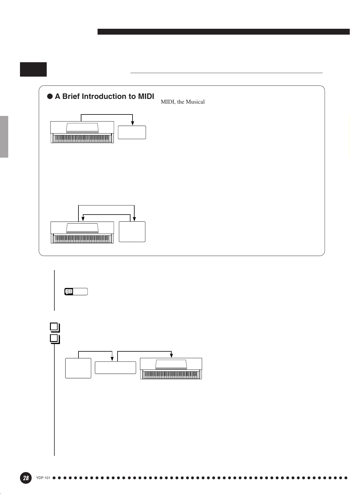
● A Brief Introduction to MIDI
MIDI Cable
MIDI OUT
YDP-101
and velocity (touch response) information via the MIDI OUT connector whenever a note is played on the
keyboard. If the MIDI OUT connector is connected to the MIDI IN connector of a second keyboard (synthesizer,
etc.) or a tone generator (essentially a synthesizer with no keyboard), the second keyboard or tone generator will
respond precisely to notes played on the original transmitting keyboard. The result is that you can effectively
play two instruments at once, providing thick multi-instrument sounds.
Data Being Recorded
Playback Data
MIDI OUT
YDP-101
MIDI IN
MIDI IN
Tone
Generator
MIDI INMIDI OUT
Sequencer
MIDI, the Musical Instrument Digital Interface, is a worldstandard communication interface that allows MIDI-compatible
musical instruments and equipment to share musical information and
control one another. This makes it possible to create “systems” of
MIDI instruments and equipment that offer far greater versatility and
control than is available with isolated instruments. For example, most
MIDI keyboards (including the YDP-101, of course) transmit note
This same type of musical information transfer is used for MIDI
sequence recording. A sequence recorder can be used to “record”
MIDI data received from a YDP-101, for example. When the recorded data is played back, the YDP-101 automatically “plays” the
recorded performance in precise detail.
The examples given above really only scratch the surface. MIDI
can do much, much more. The YDP-101 MIDI functions allow it to
be used in fairly sophisticated MIDI systems.
After selecting “F7.Y”, press the [+/YES] button to engage the MIDI function sub-mode, then use
the FUNCTION [<] and [>] buttons to select the desired MIDI function, as listed below.
NOTE
• Always use a high-quality MIDI cable to connect MIDI OUT to MIDI IN terminals. Never use MIDI cables longer
than about 15 meters, since cables longer than this can pick up noise which can cause data errors.
F7.1: MIDI Transmit Channel Selection............................................................................................
F7.2: MIDI Receive Channel Selection .............................................................................................
MIDI OUT
Sequencer
MIDI IN MIDI THRU
Tone Generator
(Set to receive on MIDI
channel 2)
YDP-101
(Set to receive on MIDI channel 1)
MIDI IN
MIDI sequence recorder could be used to “play” two different instruments or tone generators. One of
the instruments or tone generators could be set to receive only on channel 1, while the other is set to
receive on channel 2. In this situation the first instrument or tone generator will respond only to
channel-1 information transmitted by the sequence recorder, while the second instrument or tone
generator will respond only to channel-2 information. This allows the sequence recorder to “play”
two completely different parts on the receiving instruments or tone generators.
The MIDI system allows transmission
and reception of MIDI data on 16 different channels. Multiple channels have
been implemented to allow selective
control of certain instruments or devices
connected in series. For example, a single
28
YDP-101
○○○○○○○○○○○○○○○○○○○○○○○○○○○○○○○○○○○○○○○○○○○○○○○○○○○○○○○○
26
Page 29

The Function Mode
In any MIDI control setup, the MIDI channels of the transmitting and receiving equipment must
be matched for proper data transfer. A “Multi-timbre” receive mode is also available, which allows
simultaneous reception of different parts on all 16 MIDI channels, allowing the YDP-101 to play
multi-channel song data received from a music computer or sequencer. There’s also a “1-2” mode
which allows simultaneous reception on channels 1 and 2.
Use the [–/NO] and [+/YES] buttons to select the desired transmit or receive channel. The transmit channel parameter can also be turned “OFF” if you don’t want the YDP-101 to transmit any
MIDI data. To select the multi-timbre receive mode, set the receive channel to “ALL”. Select “1-2”
for multi-timbre reception on channels 1 and 2 only.
Press the [–/NO] and [+/YES] buttons simultaneously to recall the default setting: transmit = “1”;
receive = “ALL”.
NOTE
• In the dual mode, first voice data is transmitted on its set channel. Second voice data is transmitted on the
next greater channel number of the set channel. No data is transmitted if the transmit channel is set to “OFF”.
• Demo/piano song data and recorder playback data are not transmitted via MIDI.
• No MIDI reception occurs when the demo/piano song mode is engaged.
• Program change and other like channel messages received will not affect the YDP-101’s panel settings or
what is being played on the keyboard.
F7.3: Local Control ON/OFF ........................................................................................................................
“Local Control” refers to the fact that, normally, the YDP-101 keyboard controls its internal tone
generator, allowing the internal voices to be played directly from the keyboard. This situation is
“Local Control On” since the internal tone generator is controlled locally by its own keyboard.
Local control can be turned OFF, however, so that the YDP-101 keyboard does not play the
internal voices, but the appropriate MIDI information is still transmitted via the MIDI OUT connector when notes are played on the keyboard. At the same time, the internal tone generator responds to
MIDI information received via the MIDI IN connector.
When using an external MIDI device with the YDP-101, for example, Local Control should be
turned OFF when recording using the external voices only, and ON when recording the YDP-101
voices while listening to playback of the external voices.
Use the [–/NO] and [+/YES] buttons to turn local control “On” or “OFF”.
Press the [–/NO] and [+/YES] buttons simultaneously to recall the default setting “On”.
F7.4: Program Change ON/OFF...............................................................................................................
Normally the YDP-101 will respond to MIDI program change numbers received from an external
keyboard or other MIDI device, causing the correspondingly numbered voice to be selected on the
corresponding channel (the keyboard voice does not change). The YDP-101 will normally also send
a MIDI program change number whenever one of its voices is selected, causing the correspondingly
numbered voice or program to be selected on the external MIDI device if the device is set up to
receive and respond to MIDI program change numbers.
This function makes it possible to cancel program change number reception and transmission so
that voices can be selected on the YDP-101 without affecting the external MIDI device.
Use the [–/NO] and [+/YES] buttons to turn program change transmission and reception “On” or
“OFF”.
Press the [–/NO] and [+/YES] buttons simultaneously to recall the default setting “On”.
• For information on program change numbers for each of the YDP-101’s voices, refer to page 36 in the MIDI
NOTE
Data Format section.
○○○○○○○○○○○○○○○○○○○○○○○○○○○○○○○○○○○○○○○○○○○○○○○○○○○○○○○○
27
YDP-101
29
Page 30

The Function Mode
F7.5: Control Change ON/OFF ......................................................................................................
Normally the YDP-101 will respond to MIDI control change data received from an external
MIDI device or keyboard, causing the voice on the corresponding channel to be affected by
pedal and other “control” settings received from the controlling device (the keyboard voice is
not affected). The YDP-101 also transmits MIDI control change information when one of its
pedals or other appropriate controls are operated.
This function makes it possible to cancel control change data reception and transmission so
that, for example, the YDP-101 pedals and other controls can be operated without affecting an
external MIDI device.
Use the [–/NO] and [+/YES] buttons to turn control change transmission and reception
“On” or “OFF”.
Press the [–/NO] and [+/YES] buttons simultaneously to recall the default setting “On”.
F7.6: MIDI Transmit Transpose......................................................................................................
This function allows the MIDI note data transmitted by the YDP-101 to be transposed up
or down in semitone steps by up to plus or minus 12 semitones. The pitch of the YDP-101
itself is not affected.
NOTE
• For information on control changes that can be used with the YDP-101, refer to the MIDI Data Format
on page 35.
Use the [–/NO] and [+/YES] buttons to set the desired amount of MIDI transmit transposition. The range is from “–12” (down one octave) through “0” (no transposition) to “12” (up
one octave).
Press the [–/NO] and [+/YES] buttons simultaneously to recall the default setting “0”.
F7.7: Panel/Status Transmit .............................................................................................................
This function causes all the current YDP-101 panel settings (selected voice, etc.) to be
transmitted via the MIDI OUT terminal. This is particularly useful if you will be recording
performances to a MIDI sequence recorder which will be used to control the YDP-101 on
playback. By transmitting the YDP-101 panel settings and recording them on the MIDI
sequence recorder prior to the actual performance data, the YDP-101 will be automatically
restored to the same settings when the performance is played back.
Press the [+/YES] button to transmit the panel/status data. “End” will appear on the LED
display when the data has been successfully transmitted.
• See page 36 for list of the “Panel Data Contents” transmitted by this function.
NOTE
• Panel setting data that is transmitted to an external device can only be reloaded on a model of the
same type. Panel setting data can also be directly transferred to or from instruments of the same
model type.
F7.8: Bulk Data Dump ............................................................................................................................
This function is used to transmit all data stored in the Recorder memory to a MIDI data
storage device, other sequence recorders or MIDI compatible computers.
Press the [+/YES] button to begin bulk transmission. “End” will appear on the LED
display when the data has been successfully transmitted.
NOTE
• Bulk data dump will not function when the recorder is in operation.
• Recorder data that is transmitted to an external device can only be reloaded on a model of the same
type. Recorder data can also be directly transferred to or from instruments of the same model type.
• The reload operation cannot be executed when the Recorder is in operation or the Function mode is
engaged.
•
No MIDI data transmission or data reception occurs during a bulk data dump transmit operation.
YDP-101
30
○○○○○○○○○○○○○○○○○○○○○○○○○○○○○○○○○○○○○○○○○○○○○○○○○○○○○○○○
28
Page 31

The Function Mode
F8
Backup Functions
After selecting “F8.Y”, press the [+/YES] button to engage the backup function sub-mode,
then use the FUNCTION [<] and [>] buttons to select the desired backup function, as listed
below.
NOTE
• The backup settings themselves, and the contents of the recorder memory, are always backed up.
• Even if the Backup is turned on, factory presets can be recalled at any time (see page 32). The factory
setting list is found on page 34.
Even if backup is turned on via one of the functions described below, the data will only be
retained in memory for about 1 week if the power is not turned on during this time. If the
backup period is exceeded, all settings will be reset to their default values. If you want to
retain the backup settings for longer periods, be sure to turn the power switch on for a few
minutes at least once a week.
F8.1: Voice ...........................................................................................................................................................
Turns backup of the voice functions listed below on or off. Use the [–/NO] and [+/YES]
buttons to turn backup “On” or “OFF”.
The default backup mode is “OFF”.
• Voice (Keyboard, Dual)
• Dual (ON/OFF, Voice, and Dual Functions for each voice combination)
• Reverb (ON/OFF, Type, and Depth for each voice)
• Variation (ON/OFF for each voice)
• Touch Sensitivity (including the FIXED volume)
• Metronome (Beat, Volume)
• Piano Song Part Cancel Volume
F8.2: MIDI .............................................................................................................................................................
Turns backup of the MIDI functions listed below on or off. Use the [–/NO] and [+/YES]
buttons to turn backup “On” or “OFF”.
The default backup mode is “OFF”.
• Channel (Transmit, Receive) • Local ON/OFF
• Program Change ON/OFF • Control Change ON/OFF
• MIDI Transmit Transpose
F8.3: Tuning .......................................................................................................................................................
Turns backup of the tuning functions listed below on or off. Use the [–/NO] and [+/YES]
buttons to turn backup “On” or “OFF”.
The default backup mode is “OFF”.
• Transpose • Tuning • Scale (including base note)
F8.4: Pedal ..........................................................................................................................................................
Turns backup of the Left Pedal Mode on or off. Use the [–/NO] and [+/YES] buttons to
turn backup “On” or “OFF”.
The default backup mode is “OFF”.
○○○○○○○○○○○○○○○○○○○○○○○○○○○○○○○○○○○○○○○○○○○○○○○○○○○○○○○○
29
YDP-101
31
Page 32

Factory Preset Recall
All dual mode, reverb, touch sensitivity, tuning settings, and the
POWER
settings affected by the Backup Functions can be restored to their
original factory preset values by holding the C7 key (rightmost key on
the keyboard) while turning the [POWER] switch ON. This also erases
all recorder data, and sets all Backup on/off settings (F8) to “OFF”.
NOTE
• The factory setting list is found on page 34.
Troubleshooting
If you encounter what appears to be a malfunction, please check the following points before assuming
that your YDP-101 is faulty.
1. No Sound When the Power is Turned ON
Is the AC plug properly connected to the YDP-101
and an AC wall outlet? Check the AC connection
carefully. Is the MASTER VOLUME control turned
up to a reasonable listening level?
Also make sure that a pair of headphones is not
plugged into the PHONES jack, and that the Local
Control (page 29) is ON.
2. The Damper Pedal Doesn’t Work
If the damper pedal doesn’t work, or notes are
sustained even when the pedal is not pressed, make
sure that the pedal cord is properly plugged into the
main unit (page 42).
3. The YDP-101 Reproduces Radio or TV Sound
This can occur if there is a high-power transmitter in
your vicinity. Contact your Yamaha dealer.
● If “Scn” appears on the display an internal malfunction has occurred. In this case, contact your
Yamaha dealer.
4. Intermittent Static Noise
This is usually due to turning ON or OFF a household appliance or other electronic equipment which
is fed by the same AC mains line as your YDP-101.
5. Interference Appears On Radio or TV Sets
Located Near the YDP-101
The YDP-101 contains digital circuitry which can
generate radio-frequency noise. The solution is to
move the YDP-101 further away from the affected
equipment, or vice versa.
6. Distorted Sound When the YDP-101 is Connected to An External Amplifier/Speaker
System
If the YDP-101 is connected to a stereo system or
instrument amplifier and the sound is distorted,
reduce the volume of the external equipment to a
level at which the distortion ceases.
Options & Expander Modules
● Options
BC-8 Bench
A comfortable bench styled to match your Yamaha
YDP-101.
HPE-160 Stereo Headphones
High-performance lightweight dynamic headphones
with extra-soft ear pads.
YDP-101
32
○○○○○○○○○○○○○○○○○○○○○○○○○○○○○○○○○○○○○○○○○○○○○○○○○○○○○○○○
● Expander Modules
DOU-10 Disk Orchestra Unit
A range of MIDI recording and playback functions, plus Yamaha DOC software, Disklavier
PianoSoft™, and General MIDI/Standard MIDI File
disk playback capability.
30
Page 33

Demo and Piano Song List/Verzeichnis der Demo- und Piano-Songs/
Liste des morceaux de démonstration et de piano/
Lista de canciones de demostración y de piano
Voice Demo Tune Titles
Voice Name Title Composer
GRAND PIANO Fantaisie Impromptu F.F.Chopin
E.PIANO Original –
HARPSICHORD Gavotte (French Suite) J.S.Bach
STRINGS Eine Kleine Nachtmusik 3rd Mov. W.A.Mozart
PIPE OPRGAN Trio Sonata 2 J.S.Bach
• Some of the demonstration pieces listed above are short excerpts from the
original compositions. Original songs are all rights reserved (© 1999 by
YAMAHA CORPORATION).
• Bei manchen der oben aufgeführten Demo-Stücke handelt es sich um kurze
Auszüge aus den Originalkompositionen. Originalkompositionen sind
urheberrechtlich geschützt (© 1999 by YAMAHA CORPORATION).
Piano Song Titles
No. Title Composer
1 Prelude (Wohltemperierte Klavier I No.1) J.S.Bach
2 Menuett G dur BWV. Anh.114 J.S.Bach
3 Le Coucou L-C.Daquin
4 Piano Sonate No.15 K.545 1st mov. W.A.Mozart
5 Turkish March (Piano Sonate No.11 K.331) W.A.Mozart
6
12 Variationen über ein französisches Lied “Ah,vous dirai-je, maman”
7 Piano Concerto K.467 W.A.Mozart
8 Menuett G dur W.A.Mozart
9 Little Serenade J.Haydn
10 Perpetuum mobile C.M.v.Weber
11 Ecossaise L.v.Beethoven
12 Für Elise L.v.Beethoven
13 Marcia alla Turca L.v.Beethoven
14 Sonatine L.v.Beethoven
15 Romanze in F L.v.Beethoven
16 Impromptu op.90-2 F.Schubert
17 Moments Musicaux op.94-3 F.Schubert
18 Frühlingslied op.62-2 F.Mendelssohn
19 Etude op.10-5 “Black keys” F.F.Chopin
20 Etude op.10-3 “Chanson de l’adieu” F.F.Chopin
21 Etude op.10-12 “Revolutionary” F.F.Chopin
22 Nocturne op.9-2 F.F.Chopin
23 Valse op.64-1 “Petit chien” F.F.Chopin
24 Valse op.64-2 F.F.Chopin
25 Träumerei (Kinderszenen) R.Schumann
W.A.Mozart
• Certains morceaux de démonstration énumérés ci-dessus sont de courts
extraits des compositions originales. Les morceaux originaux sont protégés par
la loi sur les droits d’auteur (© 1999 par YAMAHA CORPORATION).
• Algunas de las piezas de demostración arriba mencionadas son pasajes cortos
de las composiciones originales. Las canciones originales tienen derechos
reservados (© 1999 por YAMAHA CORPORATION).
No. Title Composer
26 La prière d’une Vierge T.Badarzewska
27 Dolly’s Dreaming and Awakening T.Oesten
28 Alpenglow T.Oesten
29 Arabesque (25 Etüden) J.F.Burgmüller
30 La chevaleresque (25 Etüden) J.F.Burgmüller
31 Rondo alla Turca op.68-3 J.F.Burgmüller
32 La candeur (25 Etüden) J.F.Burgmüller
33 Innocence (25 Etüden) J.F.Burgmüller
34 Progrès (25 Etüden) J.F.Burgmüller
35 Liebesträume Nr.3 F.Liszt
36 La Viollette op.99-1 L.Streabbog
37 Blumenlied G.Lange
38 Heidenröslein G.Lange
39 The harvest time G.Lange
40 Barcarolle (Les Saisons) P.I.Tchaikovsky
41 Melody in F A.G.Rubinstein
42 Spinnerlied A.Ellmenreich
43 Tango (España) I.Albéniz
44 La Fille aux Cheveux de Lin C.A.Debussy
45 Arabesque 1 C.A.Debussy
46 Clair de lune C.A.Debussy
47 The Entertainer S.Joplin
48 Maple leaf rag S.Joplin
49 Radetzky Marsch* J.B.Strauss
50 American Patrol* F.W.Meacham
* Arranged for 4-hands.
121
YDP-101
33
Page 34

Factory Setting List/Liste der Vorgabeeinstellungen/
Liste des réglages/Lista de ajustes de fábrica
Default Backup Group
Voice GRAND PIANO
Dual Mode OFF
Reverb Type Preset for each voice
Reverb Depth Preset for each voice
Effect Type Preset for each voice
Effect Depth Preset for each voice
Touch Sensitivity MEDIUM
Volume in the FIXED Mode 64
Metronome OFF —
Metronome Time Signature 0 (no accent) F8.1
Tempo 120 —
Transpose 0 F8.3
Function
Function Default
F1 Tuning A3=440Hz
F2.1 Scale 1 (Equal Temperament) F8.3
F2.2 Base Note C
F3.1 Dual Balance Preset for each voice combination
F3.2 Dual Detune Preset for each voice combination F8.1
F3.3, F3.4 Dual Octave Shift Preset for each voice combination
F4 Left Pedal Mode 1 (soft pedal) F8.4
F5 Metronome Volume 10
F6 Piano Song Part Cancel Volume 5
F7.1 MIDI Transmit Channel 1
F7.2 MIDI Receive Channel ALL
F7.3 Local Control ON
F7.4 Program Change Send & Receive ON
F7.5 Control Change Send & Receive ON
F7.6 MIDI Transmit Transpose 0
F8 Backup All OFF
F8.1
“—”: Not memorized
Backup Group
Always backed up
F8.1
F8.2
YDP-101
34
122
Page 35

MIDI Data Format/MIDI-Datenformat/
Format des données MIDI/Formato de datos MIDI
If you’re already very familiar with MIDI, or are using a
computer to control your music hardware with computergenerated MIDI messages, the data provided in this section
can help you to control the YDP-101.
Falls Sie bereits mit MIDI vertraut sind oder einen Computer zur Erzeugung von MIDI-Steuermeldungen für die
Instrumente verwenden, können Sie sich zur Steuerung des
YDP-101 nach den im folgenden Abschnitt aufgeführten
Spezifikationen richten.
1. NOTE ON/OFF
Data format: [9nH] -> [kk] -> [vv]
9nH = Note ON/OFF event (n = channel number)
kk = Note number (Transmit: 09H ~ 78H = A-2 ~ C8 /
Receive: 00H ~ 7FH = C-2 ~ G8)*
vv = Velocity (Key ON = 01H ~ 7FH, Key OFF = 00H)
Data format: [8nH] -> [kk] -> [vv] (reception only)
8nH = Note OFF event (n = channel number)
kk = Note number: 00H ~ 7FH = C-2 ~ G8
vv = Velocity
* If received value exceeds the supported range for the selected
voice, the note is adjusted by the necessary number of octaves.
2. CONTROL CHANGE
Data format: [BnH] -> [cc] -> [vv]
BnH = Control change (n = channel number)
cc = Control number
vv = Data Range
(1) Bank Select
ccH Parameter Data Range (vvH)
00H Bank Select MSB 00H:Normal
20H Bank Select LSB 00H...7FH
Bank selection processing does not occur until receipt of next
Program Change message.
(2) Main Volume (reception only)
ccH Parameter Data Range (vvH)
07H Volume MSB 00H...7FH
(3) Expression
ccH Parameter Data Range (vvH)
0BH Expression MSB 00H...7FH
(4) Damper
ccH Parameter Data Range (vvH)
40H Damper MSB 00H...7FH
(5) Sostenuto
ccH Parameter Data Range (vvH)
42H Sostenuto 00H-3FH:off, 40H-7FH:on
(6) Soft Pedal
ccH Parameter Data Range (vvH)
43H Soft Pedal 00H-3FH:off, 40H-7FH:on
(7) Effect1 Depth ( Reverb Send Level )
ccH Parameter Data Range (vvH)
5BH Effect1 Depth 00H...7FH
Adjusts the reverb send level.
Si vous êtes très familier avec l’interface MIDI ou si vous
utilisez un ordinateur pour commander votre matériel de
musique au moyen de messages MIDI générés par
ordinateur, les données suivantes vous seront utiles et vous
aideront à commander le YDP-101.
SI usted está ya familiarizado con MIDI, o si emplea una
computadora para controlar sus aparatos musicales con
mensajes MIDI generados por computadora, los datos
proporcionados en esta sección le ayudarán a controlar la
YDP-101.
3 MODE MESSAGES
Data format: [BnH] -> [cc] -> [vv]
BnH = Control event (n = channel number)
cc = Control number
vv = Data Range
(1) All Sound Off
ccH Parameter Data Range (vvH)
78H All Sound Off 00H
Switches off all sound from the channel. Does not reset Note On
and Hold On conditions established by Channel Messages.
(2) Reset All Controllers
ccH Parameter Data Range (vvH)
79H
Reset All Controllers
Resets controllers as follows.
Controller Value
Expression 127 (max)
Damper Pedal 0 (off)
Sostenuto 0 (off)
Soft Pedal 0 (off)
(3) Local Control (reception only)
ccH Parameter Data Range (vvH)
7AH Local Control 00H (off), 7FH (on)
(4) All Notes Off
ccH Parameter Data Range (vvH)
7BH All Notes Off 00H
Switches OFF all the notes that are currently ON on the specified
channel. Any notes being held by the damper or sostenuto pedal
will continue to sound until the pedal is released.
(5) Omni Off (reception only)
ccH Parameter Data Range (vvH)
7CH Omni Off 00H
Same processing as for All Notes Off.
(6) Omni On (reception only)
ccH Parameter Data Range (vvH)
7DH Omni On 00H
Same processing as for All Notes Off.
(7) Mono (reception only)
ccH Parameter Data Range (vvH)
7EH Mono 00H
Same processing as for All Sound Off.
(8) Poly (reception only)
ccH Parameter Data Range (vvH)
7FH Poly 00H
Same processing as for All Sound Off.
• When control change is turned OFF in the Function mode,
control change data will not be transmitted or received except
for Bank Select and Mode messages.
• Local on/off, OMNI on/off are not transmitted. (The appropriate
note off number is supplied with “All Note Off” transmission).
• When a voice bank MSB/LSB is received, the number is stored
in the internal buffer regardless of the received order, then the
stored value is used to select the appropriate voice when a
program change message is received.
• The Multi-timbre and Poly modes are always active. No change
occurs when OMNI ON, OMNI OFF, MONO, or POLY mode
messages are received.
00H
123
YDP-101
35
Page 36
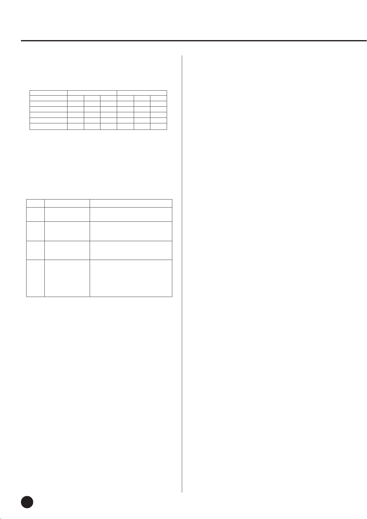
MIDI Data Format/MIDI-Datenformat/Format des données MIDI/Formato de datos MIDI
4. PROGRAM CHANGE
Data format: [CnH] -> [ppH]
CnH = Program event (n = channel number)
ppH = Program change number
Normal Voice VARIATION Voice
MSB LSB
GRAND PIANO 0 112 0 0 113 0
E.PIANO 0 112 5 0 112 88
HARPSICHORD 0 112 6 0 115 6
STRINGS 0 112 48 0 113 49
PIPE ORGAN 0 112 19 0 113 19
P.C.#=Program Change number
P.C.#
MSB LSB
• When program change is turned OFF in the Function mode, no
program change data is transmitted or received.
Also, Bank MSB/LSB is not transmitted or received.
5. SYSTEM REALTIME MESSAGES
[rrH]
F8H: Timing clock
FAH: Start
FCH: Stop
FEH: Active sensing
Data Transmission Reception
F8H Transmitted every Received as 96-clock tempo timing
96 clocks when MIDI clock is set to External
FAH Recorder start Recorder start
Not received when the MIDI clock
is set to Internal.
FCH Recorder stop Recorder stop
Not received when the MIDI clock
is set to Internal.
FEH Transmitted every If a signal is not received via MIDI
200 milliseconds for more than 400 milliseconds, the
same processing will take place for
All Sound Off, All Notes Off and
Reset All Controllers as when those
signals are received.
• Caution: If an error occurs during MIDI reception, the Damper, Sostenuto,
and Soft effects for all channels are turned off and an All Note Off occurs.
6. SYSTEM EXCLUSIVE MESSAGES
(Yamaha MIDI Format)
Panel Data Transmit
Data format: [F0H] -> [43H] -> [0nH] -> [7CH] -> ... ->
[F7H]
F0H, 43H, 0nH, 7CH (n: channel number)
00H, 2CH (
43H, 4CH, 20H, 20H (CL)
43H, 4CH, 50H, 27H, 39H, 38H (Model ID)
30H, 30H (version x, y)
[PANEL DATA]
[CHECK SUM (1byte)] = 0-(43H+4CH+20H+......+Data end)
F7H (end of exclusive)
data length
)
P.C.#
• Panel Data Contents
(1) 1'st Voice
(2) Dual On/Off
(3) Dual Voice
(4) Dual Balance
(5) Dual Detune
(6) Dual Voice1 Octave
(7) Dual Voice2 Octave
(8) —
(9) —
(10) —
(11) —
(12) —
(13) —
(14) —
(15) —
(16) —
(17) —
(18) —
(19) Reverb Type 1
(20) Reverb Type 2
(21) Reverb Depth1
(22) Reverb Depth2
(23) —
(24) —
(25) —
(26) Variation 1 On/Off
(27) Variation 2 On/Off
(28) Touch Sensitivity
(29) Fixed Data
(30) Left Pedal Function
(31) Absolute tempo low byte
(32) Absolute tempo high byte
• “—” indicates no affect.
• Panel data send requests cannot be received.
7. SYSTEM EXCLUSIVE MESSAGES
(Universal System Exclusive)
(1) Universal Realtime Message
Data format: [F0H] -> [7FH] -> [XnH] -> [04H] -> [01H] ->
[ll H] -> [mmH] -> [F7H]
MIDI Master Volume
• Simultaneously changes the volume of all channels.
• When a MIDI master volume message is received, the volume
only has affect on the MIDI receive channel, not the panel
master volume.
F0H = Exclusive status
7FH = Universal Realtime
7FH = ID of target device
04H = Sub-ID #1=Device Control Message
01H = Sub-ID #2=Master Volume
ll H = Volume LSB
mmH = Volume MSB
F7H = End of Exclusive
or
F0H = Exclusive status
7FH = Universal Realtime
XnH = When n is received n=0~F, whichever is received.
X = don’t care
04H = Sub-ID #1=Device Control Message
01H = Sub-ID #2=Master Volume
ll H = Volume LSB
mmH = Volume MSB
F7H = End of Exclusive
YDP-101
36
124
Page 37

(2) Universal Non-Realtime Message (GM On)
General MIDI Mode On
Data format: [F0H] -> [7EH] -> [XnH] -> [09H] -> [01H] ->
[F7H]
F0H = Exclusive status
7EH = Universal Non-Realtime
7FH = ID of target device
09H = Sub-ID #1=General MIDI Message
01H = Sub-ID #2=General MIDI On
F7H = End of Exclusive
or
F0H = Exclusive status
7EH = Universal Non-Realtime
XnH = When received, n=0~F.
X = don’t care
09H = Sub-ID #1=General MIDI Message
01H = Sub-ID #2=General MIDI On
F7H = End of Exclusive
When the General MIDI mode ON message is received, the MIDI
system will be reset to its default settings.
This message requires approximately 50ms to execute, so sufficient time should be allowed before the next message is sent.
8. SYSTEM EXCLUSIVE MESSAGES (XG Standard)
(1) XG Native Parameter Change
Data format: [F0H] -> [43H] -> [1nH] -> [4CH] -> [hhH] ->
[mmH] -> [ll H] -> [ddH] -> [F7H]
F0H = Exclusive status
43H = YAMAHA ID
1nH = When received, n=0~F.
When transmitted, n=0.
4CH = Model ID of XG
hhH = Address High
mmH = Address Mid
ll H = Address Low
ddH = Data
|
F7H = End of Exclusive
Data size must match parameter size (2 or 4 bytes).
When the XG System On message is received, the MIDI system
will be reset to its default settings.
The message requires approximately 50ms to execute, so sufficient time should be allowed before the next message is sent.
(2) XG Native Bulk Data (reception only)
Data format: [F0H] -> [43H] -> [0nH] -> [4CH] -> [aaH] ->
[bbH] -> [hhH] -> [mmH] -> [llH] ->
[ddH] ->...-> [ccH] -> [F7H]
F0H Exclusive status
43H YAMAHA ID
0nH When received, n=0~F.
When transmitted, n=0.
4CH Model ID of XG
aaH ByteCount
bbH ByteCount
hhH Address High
mmH Address Mid
ll H Address Low
ddH Data
| |
| |
ccH Check sum
F7H End of Exclusive
• Receipt of the XG SYSTEM ON message causes reinitialization
of relevant parameters and Control Change values. Allow sufficient time for processing to execute (about 50 msec) before
sending the YDP-101 another message.
• XG Native Parameter Change message may contain two or four
bytes of parameter data (depending on the parameter size).
• For information about the Address and Byte Count values, refer
to Table 1 below. Note that the table’s Total Size value gives the
size of a bulk block. Only the top address of the block (00H, 00H,
00H) is valid as a bulk data address.
9. SYSTEM EXCLUSIVE MESSAGES
(YDP-101 MIDI Format)
Data format: [F0H] -> [43H] -> [73H] -> [xxH] -> [nnH] ->
[F7H]
F0H = Exclusive status
43H = Yamaha ID
73H = YDP ID
5FH = Product ID
nnH = Substatus
nn Control
02H Internal MIDI clock
03H External MIDI clock
06H Bulk Data (the bulk data follows 06H)
F7H = End of Exclusive
* When nn=02H or 03H, YDP common ID (01H) is recog-
nized as well as 5FH.
BULK DUMP FORMAT
F0H, 43H, 73H
5FH =Product ID
06H =Bulk ID
05H =Sequence data
0nH, 0nH, 0nH, 0nH, 0nH, 0nH, 0nH, 0nH =Data length
[BULK DATA] =
[CHECK SUM (1byte)] = 0-sum (BULK DATA)
F7H = End of Exclusive
10. SYSTEM EXCLUSIVE MESSAGES (Special Control)
Data format: [F0H] -> [43H] -> [73H] -> [xxH] -> [11H] ->
[0nH] -> [ccH] -> [vvH] -> [F7H]
F0H = Exclusive status
43H = Yamaha ID
73H = YDP ID
5FH = Product ID
11H = Special control
0nH = Control MIDI change (n=channel number)
cc = Control number
vv = Value
F7H = End of Exclusive
Control 0n ccH vvH
Metronome Always 00H 1BH 00H : off
Channel Detune ch: 00H-0FH 43H (Sets the Detune value for
Voice Reserve ch: 00H-0FH 45H 00H : Reserve off
* When Volume, Expression is received for Reserve On, they will
be effective from the next Key On. Reserve Off is normal.
each channel)
01H : –
02H : 2/4
03H : 3/4
04H : 4/4
06H : 6/4
7FH : No accent
00H-7FH
7FH : on*
11. SYSTEM EXCLUSIVE MESSAGES (Others)
Data format: [F0H] -> [43H] -> [1nH] -> [27H] -> [30H] ->
[00H] -> [00H] -> [mmH] -> [ll H] -> [ccH] ->
[F7H]
Master Tuning (XG and last message priority) simultaneously
changes the pitch of all channels.
F0H = Exclusive Status
43H = Yamaha ID
1nH = Transmission from n=YDP-101 is always 0.
0-F is received.
27H = Model ID of TG100
30H = Sub ID
00H =
00H =
mmH = Master Tune MSB
ll H = Master Tune LSB
ccH = don’t care (under 7FH)
F7H = End of Exclusive
125
YDP-101
37
Page 38

MIDI Data Format/MIDI-Datenformat/Format des données MIDI/Formato de datos MIDI
<Table 1>
MIDI Parameter Change table ( SYSTEM )
Address (H) Size (H) Data (H) Parameter Description Default value (H)
00 00 00 4
01 1st bit 3 - 0 → bit 15 - 12 400
02 2nd bit 3 - 0 → bit 11 - 8
03 3rd bit 3 - 0 → bit 7 - 4
04 1 00 - 7F MASTER VOLUME 0 - 127 7F
05 1 — —
06 1 34 - 4C(*2) TRANSPOSE -12 - +12[semitones] 40
7E 00 XG SYSTEM ON 00=XG sytem ON
7F 00 RESET ALL PARAMETERS 00=ON (receive only)
TOTAL SIZE 07
*1: Values lower than 020CH select -50 cents. Values higher than 05F4H select +50 cents.
*2: Values from 28H through 33H are interpreted as -12 through -1. Values from 4DH through 58H are interpreted as +1 through +12.
020C - 05F4(*1)
MASTER TUNE -50 - +50[cent] 00 04 00 00
4th bit 3 - 0 → bit 3 - 0
<Table 2>
MIDI Parameter Change table ( EFFECT 1)
Refer to the “Effect MIDI Map” for a complete list of Reverb type numbers.
Address (H) Size (H) Data (H) Parameter Description Default value (H)
02 01 00 2 00-7F REVERB TYPE MSB Refer to Effect MIDI Map 01(=HALL1)
00-7F REVERB TYPE LSB 00 : basic type 00
● Effect MIDI Map
REVERB
ROOM 02H 10H
HALL 1 01H 10H
HALL 2 01H 11H
STAGE 03H 10H
MSB LSB
YDP-101
38
126
Page 39
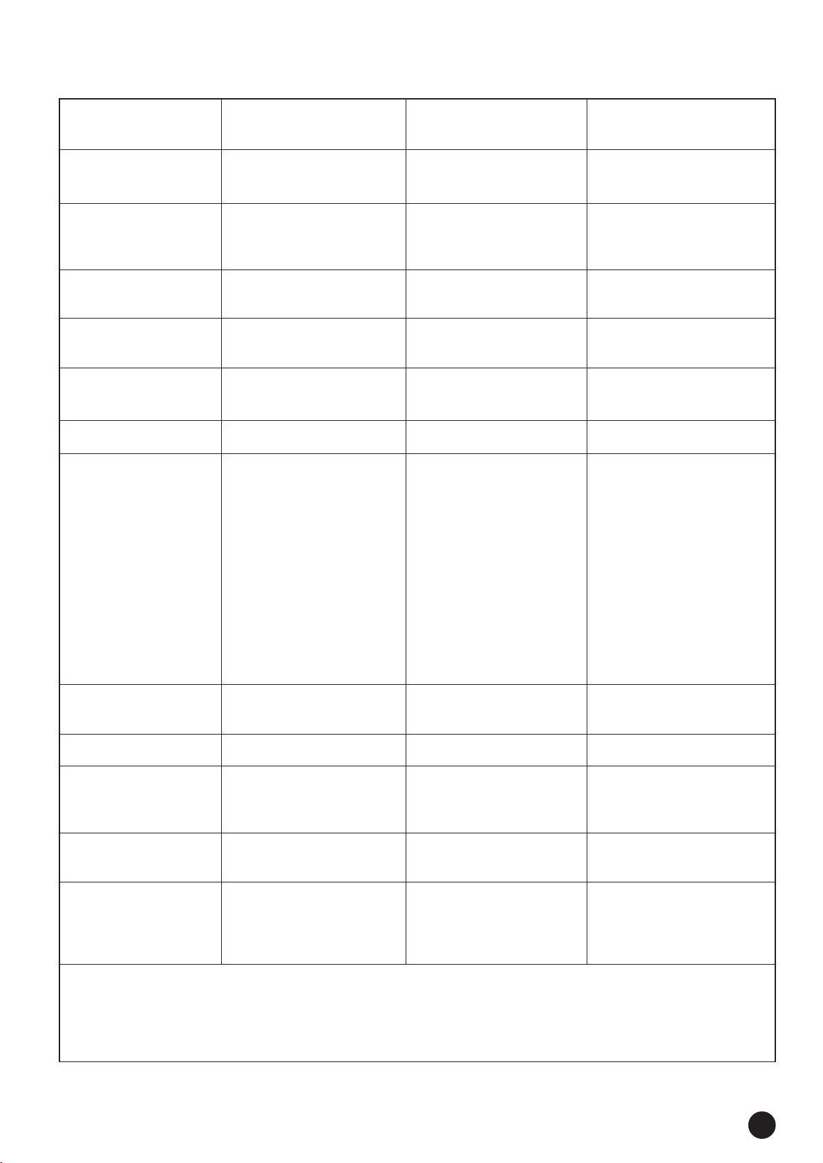
YAMAHA [Digital Piano] Date: 11/4, 1998 Model: YDP-101 MIDI Implementation Chart Version: 1.1
Function Transmitted Recognized Remarks
Basic Default 1 1
Channel Changed 1~16 1~16
Default 3 1 *1 Poly Mode only
Mode Messages XX
Altered ***************** X
Note 9~120 0~127
Number : True voice ***************** 21~108
Velocity Note on O 9nH, v=1~127 O v=1~127
Note off X 9nH, v=0 X
After key’s XX
Touch Ch’s XX
Pitch Bender XX
Control Change
0, 32 OOBank Select
07 XOVolume
11 XOExpression
64 OODamper
66 OOSostenuto
67 OOSoft pedal
91 OOReverb Depth
120 XOAll sounds off
121 XOReset All Controllers
Program OO
Change : True # *****************
System Exclusive OO
System : Song Position XX
: Song Select XX
Common : Tune XX
System : Clock OO
Real Time : Commands OO
Aux : Local ON/OFF XO
: All Notes Off OO (123~127)
Messages : Active Sense OO
: Reset XX
Notes : *1 = Recieve Mode is always multi timbre and Poly mode.
Mode 1: OMNI ON, POLY Mode 2: OMNI ON, MONO O: Yes
Mode 3: OMNI OFF, POLY Mode 4: OMNI OFF, MONO X: No
127
YDP-101
39
Page 40

1
• 6 x 35 mm round-head screws x 4 1
• 6 x 35 mm Halbrundschrauben x 4 1
• Vis à tête ronde de 6 x 35 mm x 4 1
• Tornillos de cabeza redonda
de 6 x 35 mm x 4 1
A
D
B
D
C
• 4 x 10 mm round-head screws x 2 2
• 4 x 10 mm Halbrundschrauben x 2 2
• Vis à tête ronde de 4 x 10 mm x 2 2
• Tornillos de cabeza redonda
de 4 x 10 mm x 2 2
• 4 x 16 mm tapping screws x 4 3
• 4 x 16 mm Schneidschrauben x 4 3
• Vis auto-taraudeuses 4 x 16 mm x 4 3
• Tornillos de autoenrosque
de 4 x 16 mm x 4 3
• 6 x 16 mm flat-head screws x 4 4
• 6 x 16 mm Senkschrauben x 4 4
• Vis à tête plate de 6 x 16 mm x 4 4
• Tornillos de cabeza plana
de 6 x 16 mm x 4 4
• Bundled pedal cord inside
• Gebündeltes Pedalkabel
• Cordon de pédalier enroulé à l’intérieur
• Cable de pedales enrollado en el interior
Keyboard Stand Assembly
• Be careful not to confuse parts, and be sure to install all parts in the
correct direction. Please assemble in accordance with the sequence given below.
• Assembly should be carried out by at least two persons.
• Be sure to use the correct screw size, as indicated above. Use of
incorrect screws can cause damage.
• Be sure to tighten up all screws upon completing assembly of each
unit.
• To disassemble, reverse the assembly sequence given below.
ZOpen the box and remove all the parts.
On opening the box you should find the parts shown in
the illustration above. Check to make sure that all the
required parts are provided.
XUntie the vinyl tie.
Untie the vinyl tie and straighten out the bundled cord
attached to the bottom of the pedal box. Don’t discard the
vinyl tie, you’ll need it later in step N.
CAttach the side panels (D) to the pedal box
(C).
Place the pedal box on top of the wooden blocks attached
to the side panels (D), and while eliminating any gaps
between the pedal box and side panels, attach using the
four 6 x 35 millimeter round-head screws 1 — two
screws on each side. Make sure the pedals extend in the
same direction as the side panel feet.
● Cord holders x 2
● Kabelhalter x 2
● Serre-câble x 2
● Soportes de cable x 2
● AC power cord
● Netzkabel
● Cordon d’alimentation
● Cable de alimentación de CA
Zusammenbau und Aufstellung
• Achten Sie darauf, die Teile nicht zu verwechseln, und installieren
Sie alle Teile in der richtigen Ausrichtung. Gehen Sie beim
Zusammenbau bitte in der angegebenen Reihenfolge vor.
• Die Montage sollte von mindestens zwei Personen vorgenommen
werden.
• Achten Sie darauf, die richtige Schraubengröße zu verwenden, wie
es oben gezeigt ist. Die Verwendung der falschen Schrauben kann
zu Schäden führen.
• Achten Sie während der Montage darauf, bei jedem Arbeitsgang
alle Schrauben festzuziehen.
• Für die Demontage muß die angegebene Reihenfolge umgekehrt
befolgt werden.
ZÖffnen Sie den Karton und nehmen Sie alle
Teile heraus.
Im Karton sollten die oben abgebildeten Teile enthalten
sein. Prüfen Sie zunächst bitte, ob alle Teile vollständig
vorhanden sind.
XEntfernen Sie den Kabelbinder.
Lösen Sie den Kabelbinder, um das unten am Pedalkasten
angebrachte Kabel dann bis zur vollen Länge zu ziehen.
Werfen Sie den Kabelbinder nicht weg — er wird in
Schritt N wieder gebraucht.
CBefestigen Sie die Seitenwände (D) am
Pedalkasten (C).
Stellen Sie den Pedalkasten auf die Holzblöcke an den
Seitenwänden (D), um ihn dann mit vier 6 x 35 mm Halbrundschrauben 1 (jeweils zwei Schrauben links und
rechts) so an den Seitenwänden festzuschrauben, daß kein
Zwischenraum verbleibt. Achten Sie dabei darauf, daß die
Pedale in dieselbe Richtung weisen wie die vorspringenden Teile der Füße.
40
YDP-101
○○○○○○○○○○○○○○○○○○○○○○○○○○○○○○○○○○○○○○○○○○○○○○○○○○○○○○○○
128
Page 41
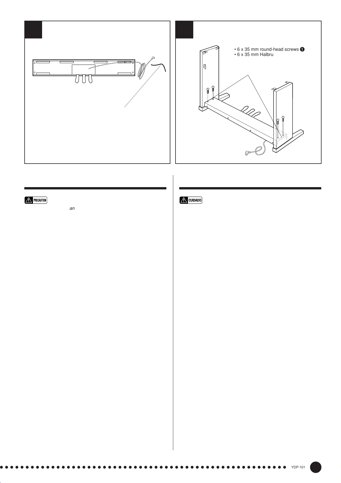
2
3
• 6 x 35 mm round-head screws 1
D
C
• 6 x 35 mm Halbrundschrauben 1
• Vis à tête ronde de 6 x 35 mm 1
• Tornillos de cabeza redonda de 6 x
35 mm 1
• This vinyl tie will be used later in step N.
• Dieser Kabelbinder wird später in Schritt N wieder gebraucht.
• Le ruban vinylique sera utilisé ultérieurement au cours de l’opé-
ration N.
• Esta abrazadera se utilizará más adelante en el paso N.
Assemblage du suppoet de clavier
• Veiller à ne pas mélanger les pièces et à les installer dans le sens
correct. Veuillez assembler l’instrument dans l’ordre indiqué cidessous.
• La présence de deux personnes minimum est nécessaire pour
procéder au montage.
• Toujours utiliser des vis aux dimensions correctes, comme indiqué
cidessus. I’utilisation de vis aux dimensions incorrectes pourrait en
effet endommager l’instrument.
• Resserrer convenablement toutes les vis après le montage de
chaque élément.
1
• Pour démonter le YDP-10
nées ci-dessous.
ZOuvrez le carton et retirez toutes les pièces
Les pièces indiquées sur l’illustration devraient toutes se
trouver dans le carton. Vérifiez qu’il n’en manque
aucune.
XDétachez l’attache en ruban vinylique
Détachez l’attache en ruban vinylique puis allonger le
cordon enroulé qui est fixé à la base du coffret de pédalier. Ne jetez pas l’attache en ruban vinylique car vous en
aurez besoin ultérieurement au cours de l’opération N.
CFixez les panneaux latéraux (D) au pédalier
(C)
Placez le coffret de pédalier sur des blocs de bois fixés
aux panneaux latéraux (D) et tout éliminant le moindre
espace entre le coffret de pédalier et les panneaux latéraux, fixez-le à l’aide de quatre vis de fixation à tête ronde
de 6 x 35 millimètres 1, deux vis de fixation à monter de
chaque côté. Vérifiez que les pédales ressortent dans le
même sens que le panneau latéral aux pieds.
, inverser l’ordre des indications don-
R
D
C
L
Conjunto del soporte del teclado
• Observe cuidado para no confundir las piezas, y asegúrese de
montar todas ellas en el sentido correcto. Proceda al montaje en el
orden indicado a continuación.
• El montaje deberá realizarse al menos por dos personas.
• Procure utilizar los tornillos del tamaño adecuado, según se indica
arriba. El empleo de tornillos inadecuados puede ocasionar daños
en el instrumento.
• Asegúrese de apretar bien todos los tornillos después de montar
cada unidad.
• Para desmontar las unidades, invierta la secuencia de montaje
facilitada a continuación.
ZAbra la caja y extraiga todas las partes.
Al abrir la caja deberá encontrar todas las partes mostradas en la ilustración. Compruebe para asegurarse que se
proporcionan todas las partes necesarias.
X Desate la abrazadera de vinilo.
Desate la abrazadera de vinilo y enderezca el cable plegado
unido a la parte inferior de la caja de pedales. No tire la abrazadera de vinilo, porque la necesitará en el paso N.
CAcople los paneles laterales (D) en la caja
de pedales (C).
Ponga la caja de pedales encima de bloques de madera
unidos a los paneles laterales (D), y mientras suprime los
huelgos entre la caja de pedales y los paneles laterales,
una empleando los cuatro tornillos de cabeza redonda de
6 x 35 milímetros 1, dos tornillos en cada lado. Asegúre-
se de que los pedales se extienden en la misma dirección
que las patas del panel lateral.
○○○○○○○○○○○○○○○○○○○○○○○○○○○○○○○○○○○○○○○○○○○○○○○○○○○○○○○○
129
YDP-101
41
Page 42

• 4 x 10 mm round-head screws 2
• 4 x 10 mm Halbrundschrauben 2
• Vis à tête ronde de 4 x 10 mm 2
• Tornillos de cabeza redonda de 4 x 10 mm 2
54
15 cm
B
• Rough surface
outward.
• Rauhe Fläche nach
außen
• Surface rugueuse
dirigée vers l’extérieur.
• Superficie redonda
hacia afuera.
• 4 x 16 mm tapping screws 3
• 4 x 16 mm Schneidschrauben 3
• Vis auto-taraudeuses 4 x 16 mm 3
• Tornillos de autoenrosque de 4 x 16 mm 3
L
VAttach the rear panel (B).
With the rear panel’s rough surface facing outward and
the panel slightly angled as shown in the illustration,
lower it onto the feet’s protruding edge at the rear of the
pedal box. Then, while eliminating any gaps between the
rear and side panels, secure the top of the rear panel to the
side panel brackets using two 4 x 10 mm round-head
screws 2. Finally, secure the bottom of the rear panel to
the pedal box using four 4 x 16 mm tapping screws 3.
BInstall the main unit (A).
Place the main unit (A) on the side panels (D) with the
screws on its bottom panel (toward the rear of the main
unit) just behind the grooves in the brackets located at the
top of the side panels. Then slide the main unit forward
until it stops. WATCH YOUR FINGERS WHEN DO-
ING THIS!!
Align the holes on the bottom panel of the main unit with
the holes in the brackets on the side panels (
also center
the main unit to produce equal clearance on the left and
right sides, as shown in the illustration), then screw in and
securely tighten the four 6 x 16 millimeter flat-head
screws 4.
• Do not hold the keyboard in any position other than the position
shown in the above illustration.
• Fingers can become pinched between the main unit and the rear or
side panels, be extra careful so as not to drop the main unit.
NConnect the pedal cord.
The pedal cord from the pedal box must be plugged into
the PEDAL connector on the rear of the main unit. Once
connected, attach the cord holders to the rear panel as
shown, then clip the cord into the holders.
A
15 cm
R
• Be sure to place your
hands at least 15
centimeters from either end of
the main unit when positioning it.
• Mindestens 15 cm innen unter die
Tastatureinheit greifen.
• Placez bien vos mains à 15 cm au moins des
extrémités du clavier, lors de sa mise en place.
• Asegúrese de colocar las manos por lo menos a 15 centímetros
desde los extremos de la unidad principal cuando la sitúe.
D
L
VMontieren Sie die Rückwand (B).
Setzen Sie die Rückwand mit der rauhen Fläche nach
außen und leicht abgewinkelt, wie in der Abbildung gezeigt, hinter dem Pedalkasten auf die hervorstehenden
Kanten der Füße auf. Schrauben Sie dann die Rückwand
oben mit zwei 4 x 10 mm Halbrundschrauben 2 so an
den Seitenwänden fest, daß kein Spiel zwischen Rückwand und Seitenwänden verbleibt. Schrauben Sie die
Rückwand abschließend noch mit vier 4 x 16 mm
Schneidschrauben 3 an den Pedalkasten.
BMontieren Sie die Tastatureinheit (A).
Setzen Sie die Tastatureinheit (A) so auf den fertigen
Ständer, daß die beiden Schrauben an ihrer Unterseite
hinter den Winkelblechen mit Führungsschlitz an der
Hinterseite des Ständers zu liegen kommen. Schieben Sie
die Tastatureinheit dann bis zum Anschlag in die Schlitze.
KLEMMEN SIE IHRE FINGER DABEI NICHT
EIN!!
Richten Sie die Schraubenbohrungen an der Unterseite
der Tastatureinheit mit den Bohrungen der Winkelbleche
achten Sie auch darauf, daß sie mittig auf dem Stän-
aus (
der steht, wie in der Abbildung gezeigt). Schrauben Sie
die Tastatureinheit dann mit den vier 6 x 16 mm Senk-
schrauben 4 am Ständer fest.
• Halten Sie die Tastatureinheit nur wie in der obigen Abbildung!
• Achten Sie darauf, daß Sie Ihre Finger nicht zwischen Tastatureinheit und den Seitenwänden bzw. der Rückwand einklemmen —
die Tastatureinheit könnte dadurch zu Fall kommen!
N Schließen Sie das Pedalkabel an.
Das vom Pedalkabel kommende Kabel wird an die
PEDAL-Buchse an der Rückseite der Tastatureinheit
angeschlossen. Bringen Sie nach dem Anschluß die
Kabelhalter an der Rückwand an, um das Kabel dann in
diese Halter zu klemmen.
D
42
YDP-101
○○○○○○○○○○○○○○○○○○○○○○○○○○○○○○○○○○○○○○○○○○○○○○○○○○○○○○○○
130
Page 43
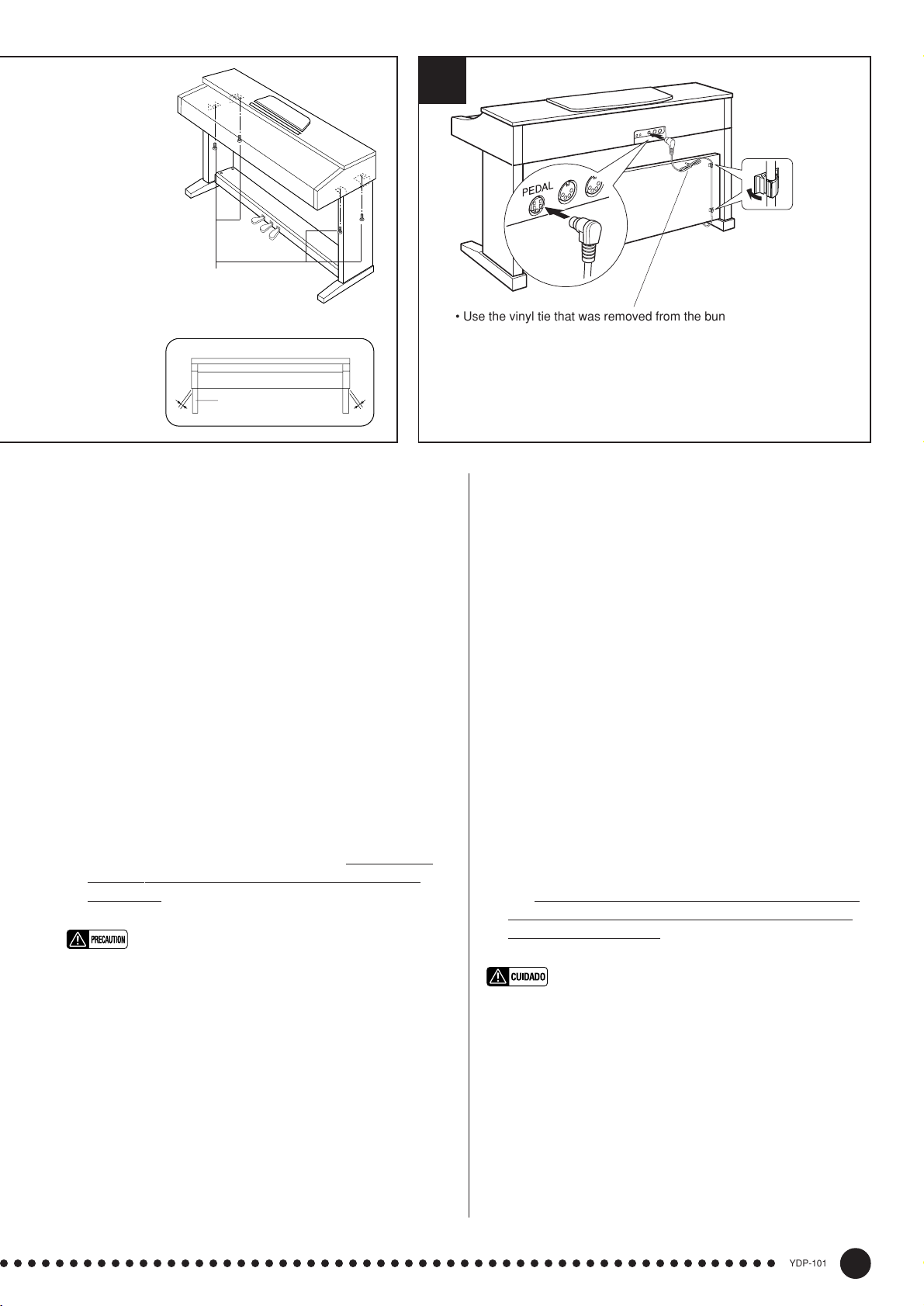
• 6 x 16 mm flat-head screws 4
• 6 x 16 mm Senkschrauben 4
• Vis à tête plate de 6 x 16 mm 4
• Tornillos de cabeza plana de 6 x 16 mm 4
A
D
6
Cord holder
Kabelhalter
Serre-câble
Soporte del cable
• Use the vinyl tie that was removed from the bundled pedal cord in
step X to tie up any slack in the pedal cord.
• Nehmen Sie überlanges Kabel mit dem in Schritt X entfernten
Kabelbinder auf.
• Utilisez l’attache en vinyle qui a été enlevée du cordon de pédalier à
l’étape X pour attacher le fil excédentaire du cordon de pédalier.
• Emplee la abrazadera de vinilo que se sacó del cale plegado de los
pedales en el paso X para fijar el cable de pedales sobrante.
VFixez le panneau arrière (B)
Tout en dirigeant la surface rugueuse du panneau arrière
vers l’extérieur et inclinant le panneau comme représenté
sur l’illustration, abaissez-le sur le rebord des pieds, à
l’arrière du pédalier. Puis, tout en éliminant les espaces
entre les panneaux arrière et latéraux, fixez le haut du
panneau arrière sur les supports des panneaux latéraux à
l’aide de deux vis à tête ronde 4 x 10 mm 2. Et finale-
ment, fixez le bas du panneau arrière au pédalier avec
quatre vis auto-taraudeuses 4 x 16 mm 3.
BPosez le clavier (A)
Placez le clavier sur les panneaux latéraux (D), avec les
vis de son panneau inférieur (situées vers l’arrière du
clavier) placées immédiatement derrière les rainures des
ferrures situées à la partie supérieure des panneaux latéraux (D), puis faites glisser le clavier vers l’avant jusqu’à
ce qu’il vienne en butée. FAITES ATTENTION A VOS
DOIGTS EN EXECUTANT CETTE OPERATION!!
Alignez les trous du panneau inférieur du clavier sur les
trous des ferrures des panneaux latéraux (
centrez également le clavier de manière à avoir un jeu identique de
chaque côté) puis posez et serrez à fond les quatre vis à
tête plate de 6 x 16 millimètres 4.
• Ne tenez pas le clavier d’une autre manière que celle indiquée sur
l’illustration ci-dessus.
• Attention car vous risquez de vous faire pincer les doigts entre le
clavier et les panneaux arrière ou latéraux de sorte que vous devez
veiller à ne pas faire tomber le clavier.
NRaccordez le câble du pédalier
Le câble du pédalier qui sort du logement de pédalier doit
être raccordé au connecteur PEDAL implanté sur la face
arrière du clavier. Une fois branché, fixez les attaches de
câble sur la face arrière en procédant de la façon représentée sur la figure puis emboîtez le câble dans les attaches.
VMonte el panel trasero (B).
Con la superficie tosca del panel trasero encarada hacia
afuera y el panel un poco inclinado en ángulo como se
muestra en la ilustración, bájelo al borde saliente de las
patas de la parte posterior de la caja de pedales. Entonces, mientras elimina los huelgos entre los paneles trasero
y lateral, fije la parte superior del panel trasero a las
ménsulas de panel lateral usando dos tornillos de cabeza
redonda de 4 x 10 mm 2. Finalmente, fije la parte infe-
rior del panel trasero a la caja de pedales usando cuatro
tornillos de autoenrosque de 4 x 16 mm 3.
BInstale la unidad principal (A).
Coloque la unidad principal en los paneles laterales (D)
con los tornillos de su panel inferior (hacia la parte posterior de la unidad principal) justo detrás de las ranuras de
la ménsula ubicada en la parte superior de los paneles
laterales (D), después deslice el teclado hacia adelante
hasta que se pare. ¡TENGA CUIDADO CON SUS DE-
DOS MIENTRAS LO HACE!
Alinee los orificios del panel inferior de la unidad principal con los orificios de las ménsulas de los paneles latera-
también centre la unidad principal para producir una
les (
holgura igual en los lados derecho e izquierdo, como se
muestra en la ilustración), después enrosque y apriete bien
los cuatro tornillos de cabeza plana de 6 x 16 mm 4.
• No sostenga el teclado en ninguna posición que no sea la posición
mostrada en la ilustración de arriba.
• Podría pillarse los dedos ente la unidad principal y los paneles
traseros o laterales, por lo que deberá tener mucho cuidado que no
se caiga la unidad principal.
NConecte el cable de los pedales.
El cable de los pedales procedente de la caja de pedales debe
enchufarse al conector PEDAL de la parte posterior de la
unidad principal. Una vez se ha conectado, coloque los soportes de cable del panel posterior como se muestra, y sujete
el cable en los soportes.
○○○○○○○○○○○○○○○○○○○○○○○○○○○○○○○○○○○○○○○○○○○○○○○○○○○○○○○○
131
YDP-101
43
Page 44

7 8
240
110
220
127
• A voltage selector is provided in some areas.
• Spannungswähler (nur in bestimmten Verkaufsgebieten)
• Un sélecteur de tension est prévu pour certaines régions
• El selector de tensión está provisto para ciertos destinos.
C
MVoltage Selector and AC power cord.
Before connecting the AC power cord, check the setting
of the voltage selector which is provided in some areas.
To set the selector for 110V, 127V, 220V or 240V main
voltages, use a “minus” screwdriver to rotate the selector
dial so that the correct voltage for your region appears
next to the pointer on the panel. The voltage selector is set
at 240V when the unit is initially shipped.
After the proper voltage has been selected, connect the
AC power cord to the AC INLET and an AC wall outlet. A
plug adaptor may be also provided in some areas to match
the pin configuration of the AC wall outlets in your area.
• An improper voltage setting can cause serious damage to the YDP101 or result in improper operation.
<Set the adjuster.
For stability, an adjuster is provided on the bottom of the
pedal box (C). Rotate the adjuster until it comes in firm
contact with the floor surface. The adjuster ensures stable
pedal operation and facilitates pedal effect control. If the
adjuster is not in firm contact with the floor surface, distorted sound may result.
■ After completing the assembly, please
check the following.
• Are there any parts left over?
➔ Review the assembly procedure and correct any errors.
• Is the YDP-101 clear of doors and other movable fixtures?
➔ Move the YDP-101 to an appropriate location.
• Does the YDP-101 make a rattling noise when you shake it?
➔ Tighten all screws.
• Does the pedal box rattle or give way when you step on the pedals?
➔ Turn the adjuster so that it is set firmly against the floor.
• Is the pedal cord inserted securely into the socket?
➔ Check the connection.
• If the main unit creaks or is otherwise unsteady when you play on
the keyboard, refer to the assembly diagrams and retighten all
screws.
MSpannungswähler und Netzkabel.
Bevor Sie nun das Netzkabel anschließen, müssen Sie den
Spannungswähler (falls vorhanden) auf die örtliche Netzspannung einstellen. Zum Verstellen drehen Sie den Spannungswähler mit einem Schlitzschraubendreher, bis der richtige
Spannungswert (110, 127, 220 oder 240) an der Pfeilmarkierung steht. Bei der Auslieferung werden alle Instrumente
mit Spannungswähler auf “240” voreingestellt.
Nachdem Sie den Spannungswähler auf den richtigen
Spannungswert eingestellt haben, stecken Sie das Netzkabel in
die AC INLET-Buchse und schließen es an eine Steckdose an.
In manchen Gebieten wird ein Steckerdapter mitgeliefert, um
den Anschluß an die evtl. unterschiedlich geformte Steckdose
zu ermöglichen.
• Eine falsche Spannungseinstellung kann das YDP-101 schwer beschädigen und Funktionsstörungen zur Folge haben.
<Justieren Sie schließlich noch den Höhenvers-
teller.
Zur Stabilisierung ist an der Unterseite des Pedalkastens (C) ein
Höhenversteller vorgesehen. Schrauben Sie den Höhenversteller
heraus, bis er fest auf dem Fußboden steht. Der Höhenversteller
sorgt für stabile Pedalbetätigung und ermöglicht eine präzise
Regelung des Betätigungshubs. Wenn er nicht fest auf dem
Boden steht, können beim Treten der Pedale Klangverzerrungen
auftreten.
■ Wenn der Zusammenbau beendet ist, prüfen
Sie bitte folgende Dinge:
• Sind Teile übrig geblieben?
➔ Gehen Sie den Vorgang des Zusammenbaus noch einmal durch
und korrigieren Sie eventuelle Fehler.
• Befindet sich das YDP-101 weit genug von Türen und anderen beweglichen Vorrichtungen entfernt?
➔ Bewegen Sie das YDP-101 an einen entsprechend sicheren Ort.
• Macht das YDP-101 Klappergeräusche, wenn Sie es schütteln?
➔ Ziehen Sie alle Schrauben fest.
• Klappert der Pedalkasten oder gibt er nach, wenn Sie das Pedal
treten?
➔ Drehen Sie den Höhenversteller, bis er fest auf dem Fußboden
steht.
• Ist das Pedalkabel fest angeschlossen?
➔ Prüfen Sie die Verbindung.
• Wenn die Tastatureinheit knarrt oder beim Spielen wackelt, betrachten
Sie die Abbildungen und ziehen Sie alle Schrauben noch einmal nach.
44
YDP-101
○○○○○○○○○○○○○○○○○○○○○○○○○○○○○○○○○○○○○○○○○○○○○○○○○○○○○○○○
132
Page 45
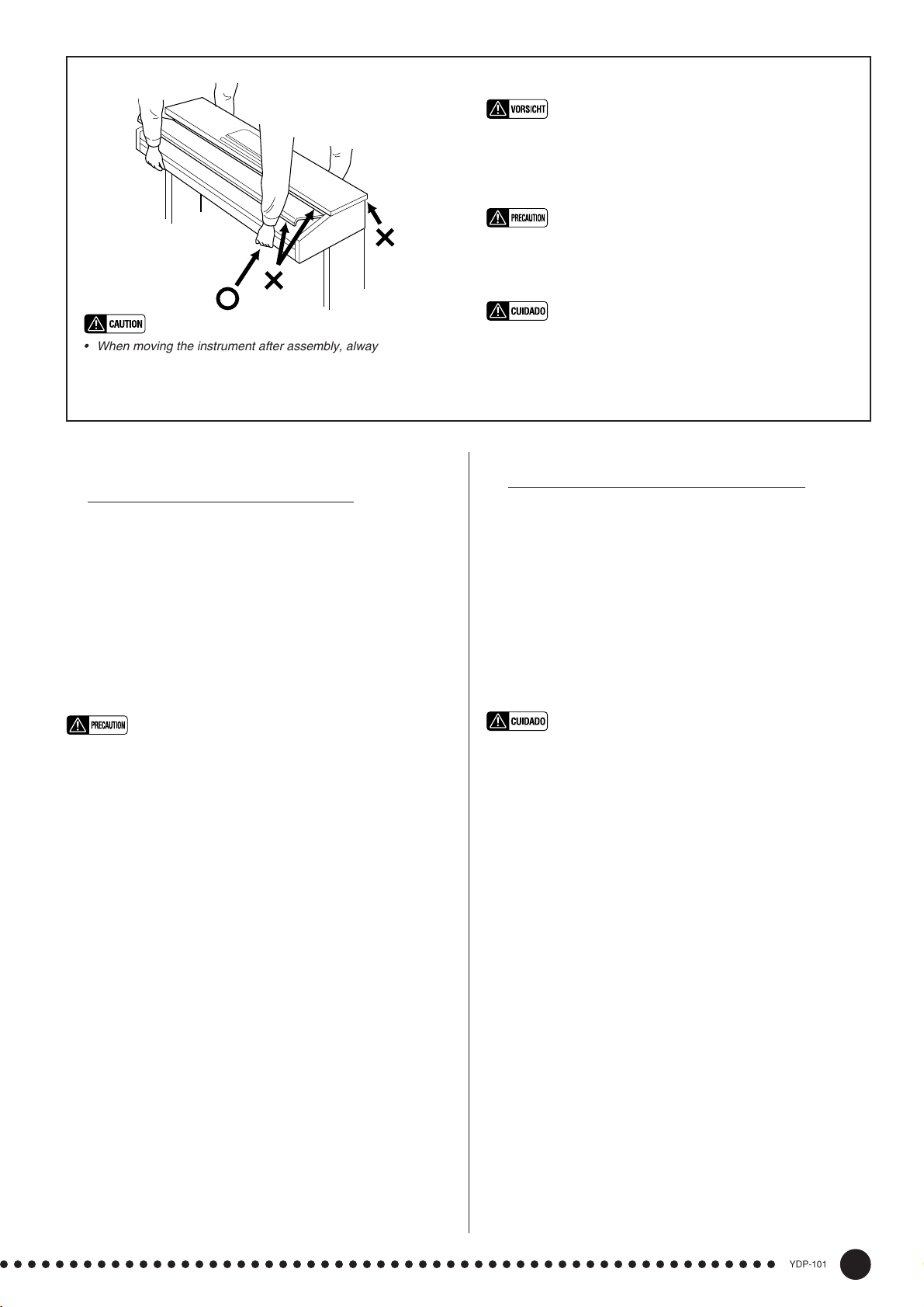
• Fassen Sie zum Umstellen des Instruments nach dem
Zusammenbau stets unter das Gehäuse; heben Sie es NIEMALS am oberen Teil. Bei Nichtbeachtung dieses Punkts kann
das Instrument beschädigt und im Extremfall eine Verletzung
hervorgerufen werden.
• Pour déplacer l’instrument après le montage, toujours tenir
l’instrument par la surface inférieure, JAMAIS par le couvercle.
Une mauvaise manipulation peut provoquer des dommages ou
des blessures.
• When moving the instrument after assembly, always hold the
lower surface of the main unit, NEVER the top portion. Improper
handling can result in damage to the instrument or personal
injury.
MSélecteur de tension et cordon d’alimentation
secteur
Avant de connecter le cordon d’alimentation, vérifiez le réglage du sélecteur de tension qui est prévu pour certaines
régions. Pour régler le sélecteur sur 110 V, 127 V, 220 V ou
240 V, utilisez un tournevis à lame plate pour tourner le cadran
du sélecteur afin de mettre l’indication correspondant à la
tension de votre région vis à vis du repère triangulaire situé
sur le panneau. Le sélecteur de tension est réglé sur 240 V au
départ d’usine.
Après avoir choisi la tension appropriée, branchez le cordon
d’alimentation secteur dans la prise AC INLET de l’instrument et une prise de sortie secteur. Un adaptateur de prise
peut également être fourni dans certaines régions pour pouvoir
brancher le cordon à la prise secteur murale.
• Vous risquez de sérieusement endommager le YDP-101 ou de
provoquer un fonctionnement anormal de l’instrument en ne choisissant pas correctement la tension d’alimentation.
<
N’oubliez pas de régler la hauteur du pédalier
Pour assurer la stabilité du pédalier (C), un dispositif de réglage a été prévu à sa partie inférieure. Tournez ce dispositif
jusqu’à ce qu’il soit en contact ferme avec la surface du sol.
Ce dispositif assure la stabilité du pédalier lors de son utilisation et facilite la commande au pied des effets. Si ce dispositif
n’est pas en contact ferme avec le sol, il pourra se produire
une distorsion du son.
• Cuando mueva el instrumento después del montaje, sostenga
siempre la superficie inferior de la unidad principal. NUNCA por
la parte superior. La manipulación indebida puede causar
daños en el instrumento o personales.
MSelector de tensión y cable de alimentación de CA
Antes de conectar el cable de alimentación de CA, compruebe el ajuste del selector de tensión que se incorpora para
ciertos destinos. Para ajustar el selector a 110V, 127V, 220V
ó 240V de la red de alimentación, emplee un destornillador
de cabeza recta “-” para girar el selector de modo que la
tensión correcta de su zona aparezca al lado del indicador del
panel. El selector de tensión se ajusta a 240V cuando la
unidad sale de fábrica.
Después de haber seleccionado la tensión correcta, enchufe
el cable de alimentación de CA a la toma AC INLET y a una
toma de corriente de la pared. En algunas zonas puede suministrarse también un adaptador para adaptar la configuración
de las patillas de los tomacorrientes de CA de su localidad.
• Un ajuste incorrecto de la tensión puede causar daños serios a la
YDP-101 o ser motivo de mal funcionamiento.
<Asegúrese de ajustar el ajustador.
Para la estabilidad del aparato, se proporciona un ajustador
en la parte inferior de la caja de pedales (C). Gire el ajustador hasta que contacte firmemente con el suelo. El ajustador
asegura una operación estable de los pedales y facilita el
control del efecto de los pedales. Si el ajustador no contacta
firmemente con el suelo, puede resultar en sonido
distorsionado.
■ Lorsque le montage est terminé, veuillez mener à bien les vérifications suivantes.
• Reste-t-il des pièces non utilisées?
➔ Passer en revue la procédure de montage et corriger toute
erreur éventuelle.
• Le YDP-101 est-il placé à l’écart des portes et de toute autre struc-
ture mobile?
➔ Déplacer le YDP-101 vers un emplacement approprié.
• Lorsque vous secouez quelque peu le YDP-101, entendez-vous un
cliquetis?
➔ Serrer convenablement toutes les vis.
• Le pédalier fait-il du bruit ou s’écarte-t-il lorsque vous appuyez sur
les pédales?
➔ Tourner le stabilisateur de sorte qu’il repose fermement sur le
sol.
• Le cordon de pédale est-il enfoncé correctement dans la prise?
➔ Vérifier toutes les connexions.
• Si la partie principale de l’appareil craque ou est instable lorsque
vous jouez sur le clavier, consulter les diagrammes de montage et
resserrer toutes les vis.
○○○○○○○○○○○○○○○○○○○○○○○○○○○○○○○○○○○○○○○○○○○○○○○○○○○○○○○○
133
■ Cuando haya concluido el montaje, compruebe los siguientes puntos:
• ¿Ha quedado alguna pieza sin instalar?
➔ Revise el procedimiento de montaje y corrija cualquier error
que se haya podido cometer.
• ¿Está el YDP-101 alejado del recorrido de puertas y muebles?
➔ Traslade el YDP-101 a una posición adecuada.
• ¿Suena algún ruido de holgura cuando se mueve el YDP-101?
➔ Apriete con firmeza todos los tornillos.
• ¿Vibra o cede la caja de pedales cuando se pisan los pedales?
➔ Gire el ajustador hasta que se apoye firmemente sobre el
suelo.
• ¿Está el cable de los pedales insertado con seguridad en el
conector?
➔ Revise las conexiones.
• Si la unidad principal cruje o presenta algún signo de inestabilidad
cuando se toca el teclado, consulte los esquemas de montajee y
vuelva a apretar todos los tornillos.
YDP-101
45
Page 46

Specifications/Technische Daten/Caractéristiques techniques/Especificaciones
KEYBOARD
POLYPHONY
VOICE SELECTORS
REVERB
TOUCH SENSITIVITY
RECORDER
PEDAL CONTROLS
OTHER CONTROLS
JACKS/CONNECTORS
OUTPUT IMPEDANCE
MAIN AMPLIFIERS
SPEAKERS
DIMENTIONS
Music stand down
(W x D x H)
Music stand up
88 KEYS (A-1 ~ C7)
32 NOTES MAX.
5 voices + Variation for each voice
ROOM, HALL 1, HALL 2, STAGE
HARD, MEDIUM, SOFT, FIXED
1, 2, START/STOP, REC
SOFT, SOSTENUTO, DAMPER
MASTER VOLUME, DEMO, TRANSPOSE, METRONOME,
TEMPO [s]/[t], FUNCTION, SONG, SONG SELECT [s]/[t], LED Display
PHONES x 2, AUX OUT R & L/L+R, MIDI IN/OUT, PEDAL
AUX OUT: Output impedance 600 Ω
20W x 2
16 cm x 2
1384 x 468 x 829 mm (54-1/2" x 18-1/2" x 32-5/8")
1384 x 468 x 1001 mm (54-1/2" x 18-1/2" x 39-3/8")
WEIGHT
• Specifications and descriptions in this owner’s manual are for information purposes only.
Yamaha Corp. reserves the right to change or modify products or specifications at any time
without prior notice. Since specifications, equipment or options may not be the same in
every locale, please check with your Yamaha dealer.
• Die technischen Daten und Beschreibungen in dieser Bedienungsanleitung dienen nur der
Information. Yamaha Corp. behält sich das Recht vor, Produkte oder deren technische
Daten jederzeit ohne vorherige Ankündigung zu verändern oder zu modifizieren. Da die
technischen Daten, das Gerät selbst oder Sonderzubehör nicht in jedem Land gleich sind,
setzen Sie sich im Zweifel bitte mit Ihrem Yamaha-Händler in Verbindung.
42.0 kg (92.6 lbs.)
• Les caractéristiques techniques et les descriptions du mode d’emploi ne sont données que
pour information. Yamaha Corp. se réserve le droit de changer ou modifier les produits et
leurs caractéristiques techniques à tout moment sans aucun avis. Du fait que les
caractéristiques techniques, les équipements et les options peuvent différer d’un pays à
l’autre, adressez-vous au distributeur Yamaha le plus proche.
• Las especificaciones y descripciones de este manual del propietario tienen sólo el propósito
de servir como información. Yamaha Corp. se reserva el derecho a efectuar cambios o
modificaciones en los productos o especificaciones en cualquier momento sin previo aviso.
Puesto que las especificaciones, equipos u opciones pueden no ser las mismas en todos
los mercados, solicite información a su distribuidor Yamaha.
46
YDP-101
○○○○○○○○○○○○○○○○○○○○○○○○○○○○○○○○○○○○○○○○○○○○○○○○○○○○○○○○
134
Page 47

For details of products, please contact your nearest Yamaha or the
authorized distributor listed below.
Pour plus de détails sur les produits, veuillez-vous adresser à Yamaha
ou au distributeur le plus proche de vous figurant dans la liste suivante.
Die Einzelheiten zu Produkten sind bei Ihrer unten aufgeführten Niederlassung und bei Yamaha Vertragshändlern in den jeweiligen
Bestimmungsländern erhältlich.
Para detalles sobre productos, contacte su tienda Yamaha más cercana
o el distribuidor autorizado que se lista debajo.
NORTH AMERICA
CANADA
Yamaha Canada Music Ltd.
135 Milner Avenue, Scarborough, Ontario,
M1S 3R1, Canada
Tel: 416-298-1311
U.S.A.
Yamaha Corporation of America,
Keyboard Division
6600 Orangethorpe Ave., Buena Park, Calif. 90620,
U.S.A.
Tel: 714-522-9011
CENTRAL & SOUTH AMERICA
MEXICO
Yamaha de Mexico S.A. De C.V.,
Departamento de ventas
Javier Rojo Gomez No.1149, Col. Gpe Del
Moral, Deleg. Iztapalapa, 09300 Mexico, D.F.
Tel: 686-00-33
BRAZIL
Yamaha Musical do Brasil LTDA.
Av. Rebouças 2636, São Paulo, Brasil
Tel: 011-853-1377
ARGENTINA
Yamaha Music Argentina S.A.
Viamonte 1145 Piso2-B 1053,
Buenos Aires, Argentina
Tel: 1-371-7021
PANAMA AND OTHER LATIN
AMERICAN COUNTRIES/
CARIBBEAN COUNTRIES
Yamaha de Panama S.A.
Torre Banco General, Piso 7, Urbanización Marbella,
Calle 47 y Aquilino de la Guardia,
Ciudad de Panamá, Panamá
Tel: 507-269-5311
EUROPE
THE UNITED KINGDOM
Yamaha-Kemble Music (U.K.) Ltd.
Sherbourne Drive, Tilbrook, Milton Keynes,
MK7 8BL, England
Tel: 01908-366700
IRELAND
Danfay Ltd.
61D, Sallynoggin Road, Dun Laoghaire, Co. Dublin
Tel: 01-2859177
GERMANY/SWITZERLAND
Yamaha Europa GmbH.
Siemensstraße 22-34, 25462 Rellingen,
F.R. of Germany
Tel: 04101-3030
AUSTRIA
Yamaha Music Austria
Schleiergasse 20, A-1100 Wien Austria
Tel: 01-60203900
THE NETHERLANDS
Yamaha Music Nederland
Kanaalweg 18G, 3526KL, Utrecht, The Netherlands
Tel: 030-2828411
BELGIUM
Yamaha Music Belgium
Keiberg Imperiastraat 8, 1930 Zaventem, Belgium
Tel: 02-7258220
FRANCE
Yamaha Musique France,
Division Claviers
BP 70-77312 Marne-la-Vallée Cedex 2, France
Tel: 01-64-61-4000
ITALY
Yamaha Musica Italia S.P.A.,
Home Keyboard Division
Viale Italia 88, 20020 Lainate (Milano), Italy
Tel: 02-935-771
SPAIN/PORTUGAL
Yamaha-Hazen Electronica Musical, S.A.
Jorge Juan 30, 28001, Madrid, Spain
Tel: 91-577-7270
GREECE
Philippe Nakas S.A.
Navarinou Street 13, P.Code 10680, Athens, Greece
Tel: 01-364-7111
SWEDEN
Yamaha Scandinavia AB
J. A. Wettergrens Gata 1
Box 30053
S-400 43 Göteborg, Sweden
Tel: 031 89 34 00
DENMARK
YS Copenhagen Liaison Office
Generatorvej 8B
DK-2730 Herlev, Denmark
Tel: 44 92 49 00
FINLAND
F-Musiikki Oy
Kluuvikatu 6, P.O. Box 260,
SF-00101 Helsinki, Finland
Tel: 09 618511
NORWAY
Norsk filial av Yamaha Scandinavia AB
Grini Næringspark 1
N-1345 Østerås, Norway
Tel: 67 16 77 70
ICELAND
Skifan HF
Skeifan 17 P.O. Box 8120
IS-128 Reykjavik, Iceland
Tel: 525 5000
OTHER EUROPEAN COUNTRIES
Yamaha Europa GmbH.
Siemensstraße 22-34, 25462 Rellingen, F.R. of
Germany
Tel: 04101-3030
AFRICA
Yamaha Corporation,
International Marketing Division
Nakazawa-cho 10-1, Hamamatsu, Japan 430-8650
Tel: 053-460-2312
MIDDLE EAST
TURKEY/CYPRUS
Yamaha Europa GmbH.
Siemensstraße 22-34, 25462 Rellingen,
F.R. of Germany
Tel: 04101-3030
OTHER COUNTRIES
Yamaha Corporation,
International Marketing Division
Nakazawa-cho 10-1, Hamamatsu, Japan 430-8650
Tel: 053-460-2312
ASIA
HONG KONG
Tom Lee Music Co., Ltd.
11/F., Silvercord Tower 1, 30 Canton Road,
Tsimshatsui, Kowloon, Hong Kong
Tel: 2737-7688
INDONESIA
PT. Yamaha Music Indonesia (Distributor)
PT. Nusantik
Gedung Yamaha Music Center, Jalan Jend. Gatot
Subroto Kav. 4, Jakarta 12930, Indonesia
Tel: 21-520-2577
KOREA
Cosmos Corporation
#131-31, Neung-Dong, Sungdong-Ku, Seoul
Korea
Tel: 02-466-0021~5
MALAYSIA
Yamaha Music Malaysia, Sdn., Bhd.
Lot 8, Jalan Perbandaran, 47301 Kelana Jaya,
Petaling Jaya, Selangor, Malaysia
Tel: 3-703-0900
PHILIPPINES
Yupangco Music Corporation
339 Gil J. Puyat Avenue, P.O. Box 885 MCPO,
Makati, Metro Manila, Philippines
Tel: 819-7551
SINGAPORE
Yamaha Music Asia Pte., Ltd.
Blk 202 Hougang, Street 21 #02-01,
Singapore 530202
Tel: 747-4374
TAIWAN
Yamaha KHS Music Co., Ltd.
10F, 150, Tun-Hwa Northroad,
Taipei, Taiwan, R.O.C.
Tel: 02-2713-8999
THAILAND
Siam Music Yamaha Co., Ltd.
121/60-61 RS Tower 17th Floor,
Ratchadaphisek RD., Dindaeng,
Bangkok 10320, Thailand
Tel: 02-641-2951
THE PEOPLE’S REPUBLIC OF CHINA
AND OTHER ASIAN COUNTRIES
Yamaha Corporation,
International Marketing Division
Nakazawa-cho 10-1, Hamamatsu, Japan 430-8650
Tel: 053-460-2317
OCEANIA
AUSTRALIA
Yamaha Music Australia Pty. Ltd.
17-33 Market Street, South Melbourne, Vic. 3205,
Australia
Tel: 3-699-2388
NEW ZEALAND
Music Houses of N.Z. Ltd.
146/148 Captain Springs Road, Te Papapa,
Auckland, New Zealand
Tel: 9-634-0099
COUNTRIES AND TRUST
TERRITORIES IN PACIFIC OCEAN
Yamaha Corporation,
International Marketing Division
Nakazawa-cho 10-1, Hamamatsu, Japan 430-8650
Tel: 053-460-2317
[CL] 18
HEAD OFFICE Yamaha Corporation, Electronic Musical Instrument Division
Nakazawa-cho 10-1, Hamamatsu, Japan 430-8650
Tel: 053-460-3273
Page 48

Yamaha Manual Library (English versions only)
http://www2.yamaha.co.jp/manual/english/
This document is printed on chlorine free (ECF) paper
with soy ink.
Auf Umweltpapier mit Sojatinte gedruckt.
Ce document a été imprimé sur du papier non blanchi
au chlore avec de l’encre d’huile de soja.
Este documento se ha impreso en papel sin cloro
alguno, con tinta de soja.
M.D.G., Pro Audio & Digital Musical Instrument Division, Yamaha Corporation
© 1999 Yamaha Corporation
V308530 012POCP5.2-11E0 Printed in Japan
Page 49

documentation manual, user maintenance, brochure, user reference, pdf manual
This file has been downloaded from:
User Manual and User Guide for many equipments like mobile phones, photo cameras, monther board, monitors, software, tv, dvd, and othes..
Manual users, user manuals, user guide manual, owners manual, instruction manual, manual owner, manual owner's, manual guide,
manual operation, operating manual, user's manual, operating instructions, manual operators, manual operator, manual product,
 Loading...