

Page 1
Page 2
Page 3

Page 4
Page 5
Feature Reference
Owner’s Manual 2
Page 6
Feature Reference
Contents
About the Manuals . . . . . . . . . . . . . . . . . . . . . . 4
■ The Getting Started Manual . . . . . . . . . . . . . . 4
■ The Feature Reference Manual (this manual) . 5
■ Conventions . . . . . . . . . . . . . . . . . . . . . . . . . . . . 5
General Operation
■ The Three Main Modes . . . . . . . . . . . . . . . . . . . 8
■ Finding Functions & Parameters . . . . . . . . . . . 9
■ Other Navigation Aids . . . . . . . . . . . . . . . . . . 11
■ Selecting & Editing Parameters . . . . . . . . . . . 12
Play Mode
■ The Main Play Mode Display . . . . . . . . . . . . . 14
■ Voice Selection . . . . . . . . . . . . . . . . . . . . . . . . 15
■ Controller Views . . . . . . . . . . . . . . . . . . . . . . . 17
■ Quick Editing In the Play Mode . . . . . . . . . . . 19
Edit Mode
■ The Voice Number Buttons In the Edit Mode 22
■ The Edit Compare Function . . . . . . . . . . . . . . 24
■ The Copy Function . . . . . . . . . . . . . . . . . . . . . 25
■ Storing Edited Data . . . . . . . . . . . . . . . . . . . . . 28
Initial Edit Page . . . . . . . . . . . . . . . . . . . . . . . . 30
Common Miscellanous . . . . . . . . . . . . . . . . . 34
■ 1: Setting . . . . . . . . . . . . . . . . . . . . . . . . . . . . . 35
■ 2: Controller . . . . . . . . . . . . . . . . . . . . . . . . . . 36
■ 3: Element Pitch . . . . . . . . . . . . . . . . . . . . . . . 37
■ 4: Element Level & Pan . . . . . . . . . . . . . . . . . 38
■ 5: Portamento . . . . . . . . . . . . . . . . . . . . . . . . . 40
■ 6: Micro Tuning . . . . . . . . . . . . . . . . . . . . . . . 42
■ 7: Continuous Slider . . . . . . . . . . . . . . . . . . . . 43
Common Effect . . . . . . . . . . . . . . . . . . . . . . . . 44
■ 1: Setting . . . . . . . . . . . . . . . . . . . . . . . . . . . . . 45
■ 2: Modulation Effect . . . . . . . . . . . . . . . . . . . . 46
• Flanger . . . . . . . . . . . . . . . . . . . . . . . . . . . 47
• Pitch Change . . . . . . . . . . . . . . . . . . . . . . 49
• Distortion . . . . . . . . . . . . . . . . . . . . . . . . . 51
■ 3: Feedback Delay . . . . . . . . . . . . . . . . . . . . . . 53
• Mono Delay . . . . . . . . . . . . . . . . . . . . . . . 53
• L,R Delay . . . . . . . . . . . . . . . . . . . . . . . . 55
• L,C,R Delay . . . . . . . . . . . . . . . . . . . . . . 57
■ 4:Reverberation . . . . . . . . . . . . . . . . . . . . . . . . 60
• Hall1, Hall2, Room1, Room2, Studio,
Plate, Space, Reverse . . . . . . . . . . . . . . . 61
Element Controller . . . . . . . . . . . . . . . . . . . . . 64
■ 1: Pressure . . . . . . . . . . . . . . . . . . . . . . . . . . . . 65
■ 2: Embouchure . . . . . . . . . . . . . . . . . . . . . . . . 66
■ 3: Pitch . . . . . . . . . . . . . . . . . . . . . . . . . . . . . . . 67
■ 4: Vibrato . . . . . . . . . . . . . . . . . . . . . . . . . . . . . 69
■ 5: Tonguing . . . . . . . . . . . . . . . . . . . . . . . . . . . 70
■ 6: Amplitude . . . . . . . . . . . . . . . . . . . . . . . . . . 71
■ 7: Scream . . . . . . . . . . . . . . . . . . . . . . . . . . . . . 72
■ 8: Breath Noise . . . . . . . . . . . . . . . . . . . . . . . . 73
■ 9: Growl . . . . . . . . . . . . . . . . . . . . . . . . . . . . . . 74
■ 10: Throat Formant . . . . . . . . . . . . . . . . . . . . . 75
■ 11: Dynamic Filter . . . . . . . . . . . . . . . . . . . . . 77
■ 12; Harmonic Enhancer . . . . . . . . . . . . . . . . . 78
■ 13: Damping . . . . . . . . . . . . . . . . . . . . . . . . . . 80
■ 14: Absorption . . . . . . . . . . . . . . . . . . . . . . . . . 81
Element Miscellaneous . . . . . . . . . . . . . . . . . 84
■ 1: Setting . . . . . . . . . . . . . . . . . . . . . . . . . . . . . 85
■ 2: Breath Noise . . . . . . . . . . . . . . . . . . . . . . . . 86
• 2-1: Breath Noise Level Key Scaling . . 88
• 2-2: Breath Noise HPF Key Scaling . . . 89
• 2-3: Breath Noise LPF Key Scaling . . . . 90
■ 3: Throat Formant . . . . . . . . . . . . . . . . . . . . . . 91
• 3-1: Throat Formant Pitch Key Scaling . 93
• 3-2: Throat Formant Amount Key
Scaling . . . . . . . . . . . . . . . . . . . . . . . 94
• 3-3: Throat Formant Intensity Key
Scaling . . . . . . . . . . . . . . . . . . . . . . . 95
• 3-4: Throat Formant HPF Key Scaling . 96
• 3-5: Throat Formant LPF Key Scaling . 97
■ 4: Mixing . . . . . . . . . . . . . . . . . . . . . . . . . . . . . 98
• 4-1: Mixing Driver Output Key Scaling 100
• 4-2: Mixing Pipe/String Output Key
Scaling . . . . . . . . . . . . . . . . . . . . . . 101
• 4-3: Mixing Tap Output Key Scaling . 102
2
• 4-4: Mixing Tap Location Key Scaling 103
Page 7

Feature Reference
■ 5: Amplitude . . . . . . . . . . . . . . . . . . . . . . . . . 104
• 5-1: Total Amplitude Level Key Scaling 104
Element Modifier . . . . . . . . . . . . . . . . . . . . . 106
■ 1: Harmonic Enhancer . . . . . . . . . . . . . . . . . 107
•1-1: Harmonic Enhancer HPF Key
Scaling . . . . . . . . . . . . . . . . . . . . . . 110
•1-2: Harmonic Enhancer Overdrive Key
Scaling . . . . . . . . . . . . . . . . . . . . . . 111
• 1-3: Harmonic Enhancer Carrier Level
Key Scaling . . . . . . . . . . . . . . . . . . 112
• 1-4: Harmonic Enhancer Modulator
Index Key Scaling . . . . . . . . . . . . . 113
• 1-5: Harmonic Enhancer Balance Key
Scaling . . . . . . . . . . . . . . . . . . . . . . 114
■ 2: Dynamic Filter . . . . . . . . . . . . . . . . . . . . . 115
• 2-1: Dynamic Filter Cutoff Key Scaling 117
• 2-2: Dynamic Filter Resonance Key
Scaling . . . . . . . . . . . . . . . . . . . . . . 118
■ 3: Equalizer Auxiliary . . . . . . . . . . . . . . . . . . 119
• 3-1: Equalizer Auxiliary HPF Key
Scaling . . . . . . . . . . . . . . . . . . . . . . 120
• 3-2: Equalizer Auxiliary LPF Key
Scaling . . . . . . . . . . . . . . . . . . . . . . 121
■ 4: Equlizer Band . . . . . . . . . . . . . . . . . . . . . . 122
■ 5: Impulse Expander & Resonator Setting . . 123
■ 6: Impulse Expander . . . . . . . . . . . . . . . . . . . 125
■ 7: Resonator . . . . . . . . . . . . . . . . . . . . . . . . . . 126
Element Envelope . . . . . . . . . . . . . . . . . . . . . 128
■ 1: Pressure . . . . . . . . . . . . . . . . . . . . . . . . . . . 129
■ 2: Embouchure & Pitch . . . . . . . . . . . . . . . . . 130
• 2-1: Embouchure & Pitch Hold Time
Key Scaling . . . . . . . . . . . . . . . . . . 132
• 2-2: Embouchure & Pitch Initial Level
Key Scaling . . . . . . . . . . . . . . . . . . 133
• 2-3: Embouchure & Pitch Decay Rate
Key Scaling . . . . . . . . . . . . . . . . . . 134
■ 3: Vibrato . . . . . . . . . . . . . . . . . . . . . . . . . . . . 135
• 3-1: Vibrato Delay Time Key Scaling . 137
• 3-2: Vibrato Attack Rate Key Scaling . 138
• 3-3: Vibrato Depth Key Scaling . . . . . . 139
• 3-4: Vibrato Speed Key Scaling . . . . . . 140
■ 4: Growl . . . . . . . . . . . . . . . . . . . . . . . . . . . . . 141
• 4-1: Growl Speed Key Scaling . . . . . . . 142
■ 5: Amplitude & Filter . . . . . . . . . . . . . . . . . . 143
• 5-1: Amplitude & Filter Attack Rate
Key Scaling . . . . . . . . . . . . . . . . . . 146
• 5-2: Amplitude & Filter Attack 1 Level
Key Scaling . . . . . . . . . . . . . . . . . . 147
• 5-3: Amplitude & Filter Decay Rate
Key Scaling . . . . . . . . . . . . . . . . . . 148
• 5-4: Amplitude & Filter Sustain Level
Key Scaling . . . . . . . . . . . . . . . . . . 149
• 5-5: Amplitude & Filter Release Rate
Key Scaling . . . . . . . . . . . . . . . . . . 150
Utility Mode
System . . . . . . . . . . . . . . . . . . . . . . . . . . . . . . 152
MIDI Bulk Dump . . . . . . . . . . . . . . . . . . . . . . 160
Disk . . . . . . . . . . . . . . . . . . . . . . . . . . . . . . . . . 162
Edit Recall . . . . . . . . . . . . . . . . . . . . . . . . . . . 172
Demo . . . . . . . . . . . . . . . . . . . . . . . . . . . . . . . 174
Appendix
Troubleshooting . . . . . . . . . . . . . . . . . . . . . . 178
Error Messages . . . . . . . . . . . . . . . . . . . . . . . 180
Specifications . . . . . . . . . . . . . . . . . . . . . . . . 184
Index . . . . . . . . . . . . . . . . . . . . . . . . . . . . . . . . 186
3
Page 8
Feature Reference
About the Manuals
The VL1 comes with two manuals — Getting Started and Feature
Reference. If you’re just starting out with the VL1 we urge you to begin
with the Getting Started manual since it describes basic concepts and
procedures that are essential to proper operation of the VL1.
The Getting Started Manual
The Getting Started manual contains seven chapters that take you through
essential information and procedures you will need to know to become familiar
with your VL1:
1. VL1 Basics [≥ Page 8]
Basic concepts you’ll need to understand in order to get the
most out of the VL1.
2. The Controls & Connectors [≥ Page 16]
Brief descriptions of the VL1 controls and connectors, and their
functions.
3. Setting Up [≥ Page 22]
System connections, powering up, playing the demo, calibrating
the Breath Controller, and loading the pre-programmed voices.
4. Voice Selection [≥ Page 34]
Several ways to select and play the VL1’s 128 voices.
5. The Controllers [≥ Page 38]
The VL1 controllers and how they can be assigned and edited
for optimum control.
6. Mixing & The Modifiers [≥ Page 48]
Customizing the sound to suit your own personal needs.
7. Effects [≥ Page 58]
An overview of the built-in digital effects that you can use to
add depth and ambience to the VL1 sound.
We recommend that you go through the chapters in sequence and actually
try out the various operations described. Once you’ve gone through the entire
Getting Started manual in this way, you should be familiar enough with the VL1
to need only the VL1 Feature Reference manual in future.
4
Page 9
Feature Reference
The Feature Reference Manual (this manual)
The Feature Reference manual is the “nuts and bolts” reference for
the VL1, individually describing its many functions in detail. The Feature
Reference manual is divided into five main sections, each describing the
various functions within a particular VL1 edit or utility mode.
1. General Operation [≥ Page 7]
2. Play Mode [≥ Page 13]
3. Edit Mode [≥ Page 21]
4. Utility Mode [≥ Page 151]
5. Appendix [≥ Page 177]
Once you have become familiar with the way the VL1 works by
going through the Getting Started manual, you should only need to refer
to the Feature Reference manual from time to time to get details on functions you’ve never used before, or refresh your memory about functions
that you don’t use very often.
Each section of the Feature Reference manual has its own table of
contents, so you should be able to locate any particular function quickly
and easily. Functions and references can also be located by referring to the
index at the back of the manual.
The following conventions are used through the VL1 manuals to
avoid confusion and make the text easier to read.
Buttons & Controls
Button and control names used on the VL1 panel appear in the text
in capital letters within a border: “the [ button”, for example.
Parameter Names
Parameter names and other labels which appear on the VL1 display
are printed in the courier typeface for easier identification: for
example, “adjust the “Balance” parameter as required”.
Parameter Ranges
An ellipsis is used to indicate a range of parameter values: e.g. “0
… 127”. This minimizes the confusion sometimes caused by the use
of a hyphen or dash for this purpose.
Conventions
5
Page 10

Page 11
General Operation
The VL1 makes operation as easy as possible
by providing a consistent, logical control interface via
which its many functions and parameters can be
accessed and edited. Once you become familiar with
the system, operation should be smooth, efficient, and
easy.
● The Three Main Modes . . . . . . . . . . . . . 8
● Finding Functions & Parameters . . . . . 9
● Other Navigation Aids . . . . . . . . . . . . . 11
● Selecting & Editing Parameters . . . . . 12
Page 12
Feature Reference●General Operation
The Three Main Modes
The VL1 has three main modes: PLAY, EDIT, and UTILITY. Each of these modes
can be directly accessed by pressing the P, E, or U button, respectively.
The PLAY mode is the one you use to select and play the VL1 voices.
The PLAY mode also includes several “Controller Views” that allow you
PLAY
EDIT
UTILITY
to check controller assignments, the status of several important
performance parameters, and the continuous slider assignments.
≥
Pages 13 through 19.
All voice editing functions are accessed via the EDIT mode: controller
assignments, mixing, modifiers, effects, and more.
≥
Pages 21 through 150.
The UTILITY mode includes a range of functions that affect overall
operation of the VL1 rather than individual voices. For example: master
tuning, MIDI settings, disk operations, etc.
≥
Pages 151 through 175.
8
Page 13
Feature Reference●General Operation
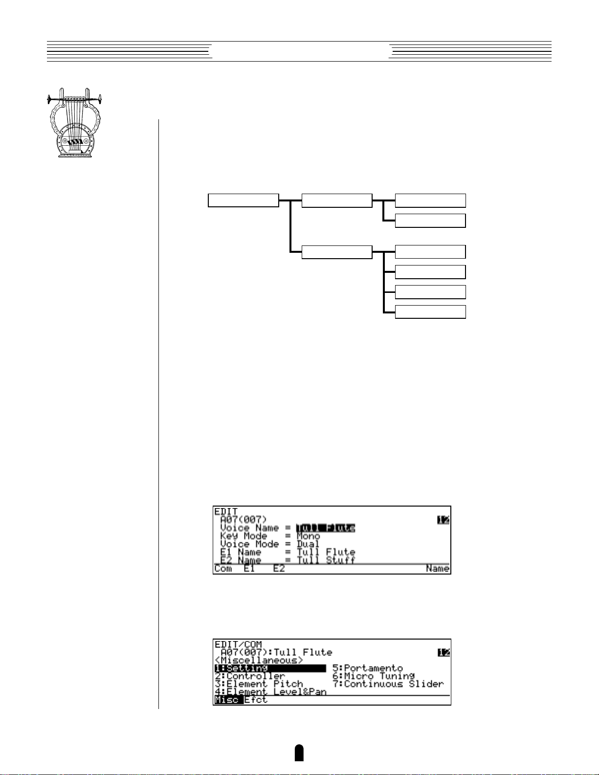
Finding Functions & Parameters
To facilitate access to the many functions provided, the EDIT and UTILITY mode
functions are organized into logical groups arranged in a hierarchical structure (the PLAY
mode is simple enough that it doesn’t require this type of structure). The basic structure
of the EDIT mode, for example, looks like this:
EDIT MODE
Here you can see that the EDIT mode functions are divided into two main groups:
COMMON and ELEMENT, and that these are further sub-divided into related groups of
functions. The COMMON EFFECT group, for example, includes all the effect parameters
(flange, reverb, etc.) that apply to the entire voice. Here’s how you would access the
reverb parameters, starting from the PLAY mode:
Example: Locate the Effect Reverb Parameters
●
COMMON
ELEMENT
MISCELLANEOUS
EFFECT
CONTROLLER
MISCELLANEOUS
MODIFIER
ENVELOPE
1. Press E
Pressing the E button from the PLAY or UTILITY mode will normally take
you to the initial EDIT display page (if the current voice has already been edited but not
stored, you will automatically return to the last EDIT mode page that was selected).
2. Press ¡ (“Com”)
Since you want the effect functions, which are in the common group, press the ¡
function button (immediately below “Com” on the display).
9
Page 14
Feature Reference●General Operation
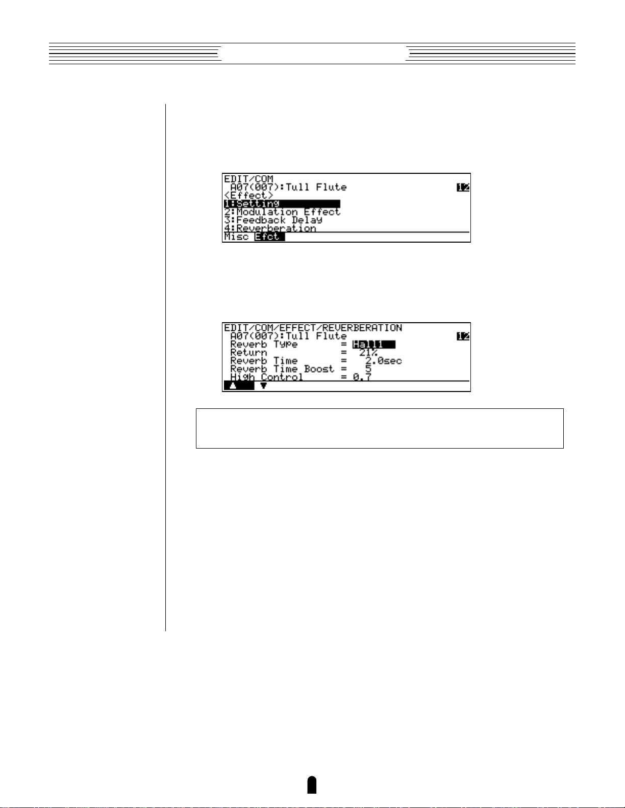
3. If Necessary, Press ™ (“Efct”)
If the miscellaneous directory is showing (in this case “Misc” above the ¡ button
will be highlighted), press the ™ button below “Efct” on the display to select the
effect directory.
4. Move the Cursor To “4:Reverberation” and Press [
Use the cursor buttons (or the - and = buttons, or the data dial)
to move the cursor to “4:Reverberation” and press the [ button. This will
take you to the first page of reverb parameters.
NOTES ■ Notice t hat t he t op line of t he display shows t h e “ pat h” t o t he current
level or f unct ion : “
This example illustrates the two methods used to move downward through the EDIT
mode levels: 1) press the appropriate function button and 2) move the cursor to the
desired selection and press [.
From any point within the structure you can move upward toward the topmost level
(in this case the initial EDIT mode display) by pressing the ] button. You move up
one level each time the ] button is pressed, until the topmost level is reached.
To exit from the EDIT mode itself you must press either the P or U
button, depending on the mode you want to switch to. You can exit from the EDIT mode
at any level by doing this, and you will be returned automatically to the same display
page the next time you press the E button as long as the voice being edited is not
stored or a new voices is not selected.
EDIT/COM/EFFECT/REVERBERATION
” .
10
Page 15

Feature Reference●General Operation
Other Navigation Aids
In addition to the standard procedures described in the previous section, the VL1
sometimes provides additional help in moving between related functions via the function
buttons.
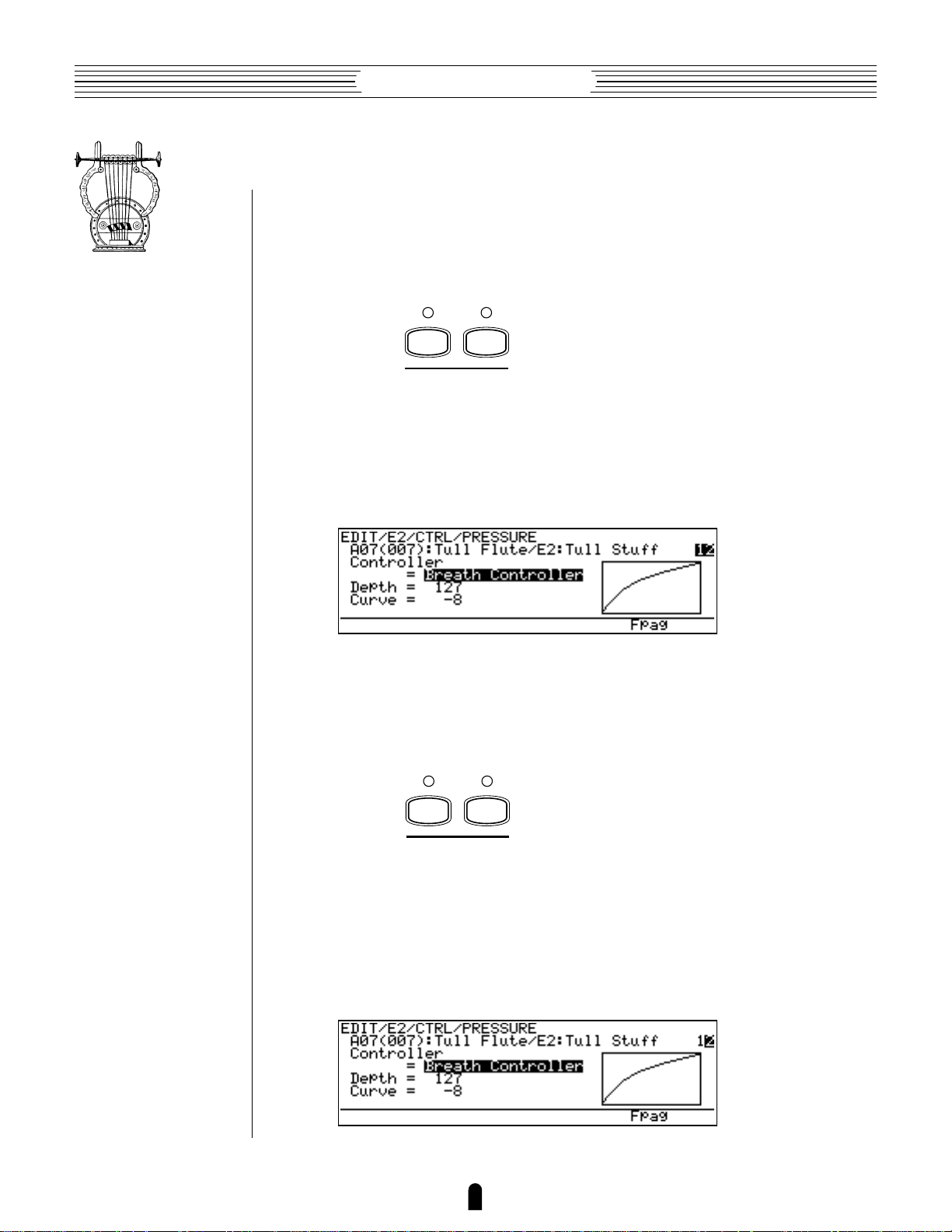
In this example display page from the ELEMENT CONTROLLER group, “Bpag”
(back page) and “Fpag” (forward page) appear above the § and ¶ function buttons.
In this case these buttons can be used to move forward and backward through the entire
list of controller functions so you don’t have to move up to the function directory and
then down to the next function every time you want to select a different element controller page.
Also note the “Para” (Parameter) abbreviation above the • button. This enables
you to go directly to the parameters related to the current page: in this case the vibrato
parameters.
From here you can go back to the vibrato controller page by pressing the •
function button again (note that it is now labelled “Ctrl”), or to the vibrato key scaling
parameters by pressing ¶, below “KSC” on the display.
Another variation appears in the COMMON EFFECT parameter displays. In most
cases the number of parameters available for each effect exceeds the capacity of the
display, so the ¡ and ™ function buttons are used to scroll up and down the parameter
list — note the “>” and “<” arrows above the buttons in the display.
11
Page 16
Feature Reference●General Operation
Selecting & Editing Parameters
Once you’ve locate the display page that contains the parameter(s) you want to edit,
simply use the cursor buttons to move the cursor to the parameter, and then use the data
dial or the = and - buttons to set the parameter as required. The data dial is ideal
for quickly covering a large range of settings, while the = and - buttons are best
for small stepwise changes.
12
Page 17
Play Mode
The primary function of the PLAY mode is to
allow you to select and play voices. The VL1 play
mode additionally offers a range of controller views
that let you check controller assignments, and simple
“quick edit” capability. Select the PLAY mode from
either the EDIT or UTILITY mode by pressing the
P button.
● The Main Play Mode Display . . . . . . . 14
● Voice Selection . . . . . . . . . . . . . . . . . . 15
● Controller Views . . . . . . . . . . . . . . . . . 17
● Quick Editing In the Play Mode . . . . . 19
Page 18
Feature Reference●Play Mode
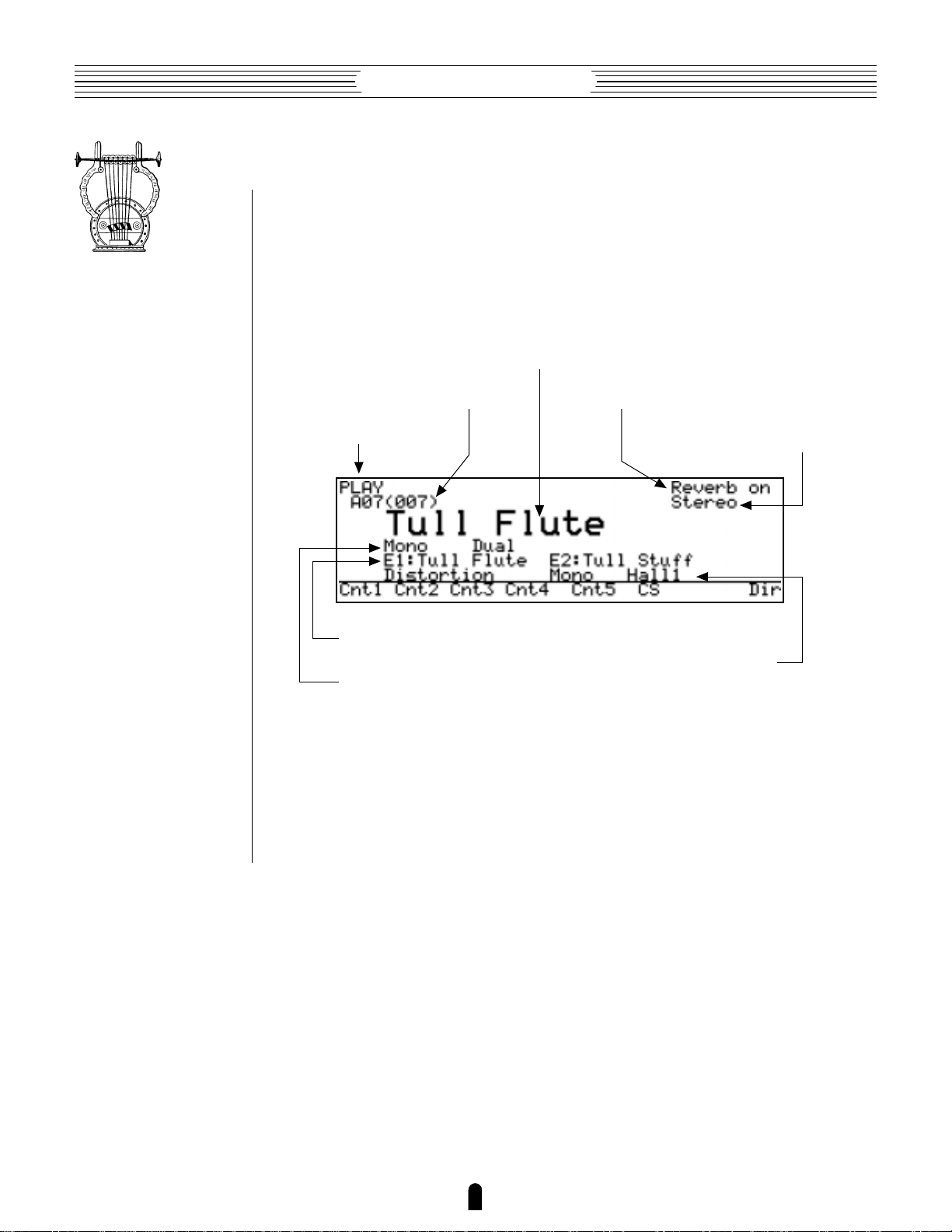
The Main Play Mode Display
When you select the PLAY mode by pressing the P button, the main PLAY
mode display will appear. This display includes a considerable amount of information in
addition to the name of the currently selected voice.
■ The Normal Voice Display
Voice name.
Voice number.
Play mode.
Element E1 and E2 names.
Voice mode.
Reverb on or off.
Stereo output mode.
Effects in use.
The abbreviations in the section separated by a line at the bottom of the display
(“Cnt1”, “Cnt2”, etc) indicate the functions of the corresponding function buttons
below the display (described below).
14
Page 19

Feature Reference●Play Mode
Voice Selection
The VL1’s 128 voices are organized into 8 banks of 16 voices each (8 x 16 = 128).
Any voice can be selected by specifying its bank using the bank keys (a through h),
and its number using the voice number keys (1 through ^).
To select voice “A7”, for example, first press the bank a key and then the voice
number 7 key. The bank a key indicator will flash until the voice number 7 key is
pressed and the D7 voice is actually engaged.
A
1
E1
9
ALL
B
2
E2
10
HE
C
3
E1
ELEMENT ON / OFFELEMENT SELECT
11
DF
MODIFIER ON / OFF
D
4
E2
12
EQ
ALL
13
IE
E
5
F
6
MOD
EFFECT ON / OFF
14
RSN
FBD
G
7
15
H
8
REV
16
Note that when you select a different bank (or press the same bank button)
the voice directory for the selected bank will appear on the display, showing the names
of all voices in that bank with the cursor located at the currently selected voice number.
The VL1 returns to the normal voice display as soon as you specify the voice number.
You can also press the [ button if you want to stay with the same voice number.
To select a different voice within the same bank it is only necessary to press the
appropriate voice number key. To select a different bank, however, you’ll always have to
press both a bank key and a voice number key (or the [ key). This prevents unwanted voices from being selected until you’ve actually specified both the bank and
number of the voice you want to use.
15
Page 20

Feature Reference●Play Mode
Alternate Voice Selection Methods
● = and - Buttons
These are best for small, step-wise changes —
e.g. selecting adjacent voice numbers, or
DEC INC
● Data Dial
numbers that are only a few steps away. Press
the = or - key briefly to decrement or
increment the voice number by one, or hold
either key for continuous decrementing or
incrementing in the corresponding direction.
The bank will switch automatically if you
cross a bank voice-number boundary.
The data dial provides a fast, efficient way to
cover a broad range of voice numbers when,
for example, you’re looking for a voice but
don’t know the voice number. Simply rotate
the data dial clockwise for higher voice
numbers or counter-clockwise for lower voice
numbers while watching the display. The
banks are automatically switched when necessary as the voice numbers are changed.
●
Using the Voice Directory
Although the voice directory appears automatically any time you select a bank, you
can have the directory displayed continuously if you find it more convenient than the
normal voice display. To switch to the voice directory display, press the • button —
located directly below “Dir” on the display. Voices are selected using the same methods
described above, and the cursor will move to the selected voice.
To return to the normal voice display press the ] or P button.
16
Page 21
Feature Reference●Play Mode
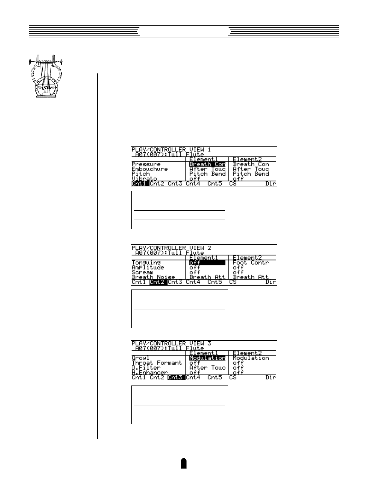
Controller Views
In the PLAY mode, function buttons ¡ (“Cnt1”) through § (“CS”) are used to
select “controller view” displays that list all controller assignments for the currently
selected voice. You can press the ] or P button from any controller view to
return to the normal play-mode display.
¡
●
¡
(“Cnt1”)
(“Cnt1”) through
¡ through ¢ display the assignments for the controller parameters.
¢
(“Cnt4”): Main Controllers
™
(“Cnt2”)
£
(“Cnt3”)
Pressure
Embouchure
Pitch
Vibrato
Tounguing
Amplitude
Scream
Breath Noise
≥
≥
≥
≥
≥
≥
≥
≥
Page 65.
Page 66.
Page 67.
Page 69.
Page 70.
Page 71.
Page 72.
Page 73.
Growl
Throat Formant
Dynamic Filter
Harmonic Enhancer
17
≥
≥
≥
≥
Page 74.
Page 75.
Page 77.
Page 78.
Page 22

Feature Reference●Play Mode
¢
(“Cnt4”)
≥
≥
Page 80.
Page 81.
Damping
Absorption
The controller parameters are listed in the left column of the controller view display, and the controllers assigned to them are listed in the center and right columns,
corresponding to elements 1 and 2, respectively.
∞
●
(“Cnt5”): Other Controller Settings
If you press the ∞ function button from the play mode you’ll see the following
controller view:
Polyphony
Sustain
Pitch Bend
Portamento
Effect
≥
≥
≥
≥
≥
Page 36.
Page 35.
Page 35.
Page 40.
Page 45.
The controller parameters listed in this screen are not in the same category as those
discussed in the preceding section, and therefore need to be introduced separately. All of
the related parameters will be discussed in detail in the Feature Reference manual (pages
listed below).
18
Page 23

Feature Reference●Play Mode
●
§
(“CS”): Continuous Sliders
The § function button calls the Continuous Slider (“CS”) controller view, which
will look something like this:
The continuous sliders — – and ≠ — can be independently assigned to
several parameters that you can control in real time while playing (also see “Quick
Editing In the Play Mode”, below). The parameters available for editing via the continuous sliders are individually preset for each voice. You can select from the available range
by using the “Continuous Slider” assignment function (≥ Page 43).
The continuous slider view shows you which parameters are assigned to which
controller as well as the current positions of the controllers and their corresponding
values.
Quick Editing In the Play Mode
Although detailed voice editing is carried out in the EDIT mode, the – and ≠
sliders on the VL1 panel can be used to change the assigned parameters in real time
while playing in the PLAY mode. This can be used simply an expressive tool, or as a
way to actually change the sound of the voice to suit your individual musical requirements. Since the – and ≠ sliders actually edit the parameters to which they are
assigned, the “new” voice created by using the sliders can be stored to one of the VL1’s
voice memory locations and used just as if it had been edited in the EDIT mode (≥ the
STORE operation is described on page 28). The parameters available for editing via the
– and ≠ sliders are individually preset for each voice. You can select from the
available range by using the “Continuous Slider” assignment function (≥ Page 43).
19
Page 24

Page 25
Edit Mode
All voice editing functions are accessed via the
EDIT mode: controller assignments, mixing, modifiers, effects, and more.
● The Voice Number Buttons
In the Edit Mode . . . . . . . . . . . . . . 22
● The Edit Compare Function . . . . . 24
● The Copy Function . . . . . . . . . . . . 25
● Storing Edited Data . . . . . . . . . . . 28
Initial Edit Page . . . . . . . . . . . . . . . . . . . 30
Common Miscellanous . . . . . . . . . . . . . . 34
Common Effect . . . . . . . . . . . . . . . . . . . . 44
Element Controller . . . . . . . . . . . . . . . . . 64
Element Miscellaneous . . . . . . . . . . . . . 84
Element Modifier . . . . . . . . . . . . . . . . . 106
Element Envelope . . . . . . . . . . . . . . . . . 128
Page 26
Feature Reference●Edit Mode
The Voice Number Buttons In the Edit Mode
In the EDIT mode, voice number buttons 1 through 14 assume the functions listed
in purple below the buttons.
Element Select
●
1
E1
ELEMENT SELECT
2
E2
These buttons select the element to be edited in a 2-element voice when an ELEMENT parameter is selected. The currently selected element is indicated by the indicators
above the ELEMENT SELECT buttons, and in the function name at the top of the
display page: “E1” for element 1 and “E2” for element 2.
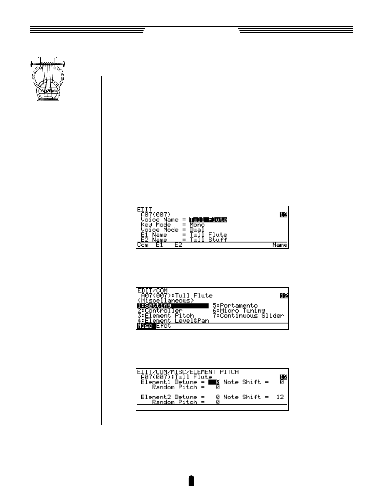
In the example display below, element 2 is selected for editing (“EDIT/E2/
CTRL/PRESSURE”):
The ELEMENT SELECT buttons will not function when a COMMON parameter is
selected. Of course, “E2” can only be selected in a voice that uses two elements. Singleelement voices use only “E1”.
●
Element On/Off
While editing a 2-element voice it is handy to be able to turn one or the other
element off so you can clearly hear the result of edits to the element you are working on.
The ELEMENT ON/OFF buttons perform this function. The on/off status of the elements
is indicated by the indicators above the ELEMET ON/OFF buttons, and by the element
numbers (“12”) at the right end of the second display line: a highlighted number indicates that the element is on, a plain number that the element is off. In the following
display, for example, element 2 is on while element 1 is off:
3
E1
ELEMENT ON / OFF
4
E2
22
Page 27
Feature Reference●Edit Mode
●
Effect On/Off
5
ALL
6
MOD
EFFECT ON / OFF
FBD
7
8
REV
The VL1’s internal digital signal processor provides three effect stages: Modulation,
Feedback Delay, and Reverb. Each stage includes a number of effects. The Modulation,
Feedback Delay, and Reverb stages can be used simultaneously, but only one of the
effects available in each stage can be used at a time.The EXTERNAL EFFECT ON/OFF
buttons can be used to individually or simultaneously turn these effects on of off. The
current status of the effect stages is shown by the indicators above the MOD, FBD, and
REV buttons.
ALL
MOD
FBD
REV
Modifier On/Off
●
Alternately turns all three effect stages on or off.
Alternately turns the Modulation effect stage on or off.
≥
Page 46.
Alternately turns the Feedback Delay effect stage on or off.
≥
Page 53.
Alternately turns the Reverb effect stage on or off.
≥
Page 60.
9
ALL
10
HE
11
DF
MODIFIER ON / OFF
12
EQ
13
IE
14
RSN
These buttons independently or simultaneously turn the VL1’s modifier stages on or
off. This allows fast on/off comparisons that make it easy to hear even subtle changes
produced by editing the modifier parameters.
ALL
HE
DF
EQ
IE
RSN
Alternately turns all five modifier stages on or off.
Alternately turns the Harmonic Enhancer stage on or off.
≥
Page 107.
Alternately turns the Dynamic Filter stage on or off.
≥
Page 115.
Alternately turns the Frequency Equalizer stage on or off.
≥
Page 119.
Alternately turns the Impulse Expander stage on or off.
≥
Page 123.
Alternately turns the Resonator stage on or off.
≥
Page 126.
23
Page 28
Feature Reference●Edit Mode
The Edit Compare Function
When editing a voice in the EDIT mode, a copy of the original voice is retained in
the VL1 “edit buffer”, allowing the edited voice to be compared with the edited version
by using the “Edit Compare” function.
The Edit Compare function is engaged by pressing the E button while in the
EDIT mode (after making at least one change to the voice data). When the Edit Compare
mode is engaged the E indicator will flash, the inverse “E”(´) before the voice
number will disappear, and the sound of the original (pre-edit) voice can be monitored.
Press the E button again to return to the EDIT mode and the edited version of the
voice. You can toggle back and forth between the edited and original voices while editing
to monitor the effect of changes you make to the voices parameters.
NOTES ■ Editi ng can not be carried out while t h e Edit Com pare funct io n is
engaged.
24
Page 29
Feature Reference●Edit Mode
The Copy Function
The copy function makes it possible to copy common or element data from any
specified voice to the current voice. You can copy all common or element data, or only
the data from a specified group of functions or a single function. It is also possible to
copy the original (pre-edit) data from the voice being edited to restore the specified data
to its original values.
Procedure
●
1. Specify the Data You Want To Copy
In the EDIT mode select the display page and function corresponding to the data
you want to copy:
• To copy all common data, go to the initial EDIT mode display and move the
cursor to the “Voice Name”, “Key Mode”, or “Voice Mode” parameter.
■ Example: Copy all common data.
• To copy all common miscellaneous data select the miscellaneous directory, or
to copy all common effect data select the Effect directory.
■ Example: Copy all common miscellaneous data.
• To copy the data from a single common miscellaneous or common effect
function select the display page for that function.
■ Example: Copy the common miscellaneous element pitch data.
25
Page 30
Feature Reference●Edit Mode
• To copy all element data, go to the initial EDIT mode display and move the
cursor to the “E1 Name” or “E2 Name” parameter.
■ Example: Copy all element data.
• To copy the E1 or E2 controller, miscellaneous, modifier, or envelope data,
select the corresponding directory display page.
■ Example: Copy all E1 element modifier data.
• To copy the data from a single element function select the display page for
that function.
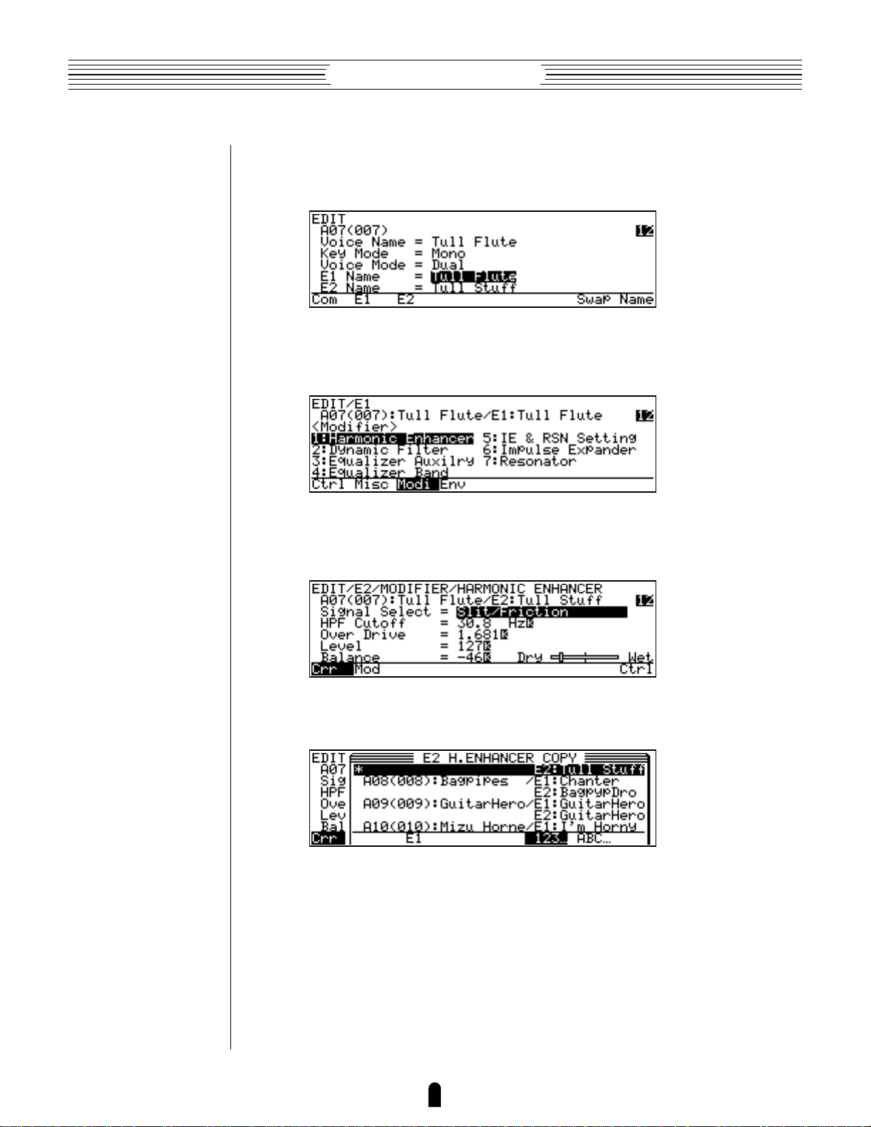
■ Example: Copy the E2 harmonic enhancer data.
2. Press C
Press the C button to call the COPY display.
3. Select the Voice You Want To Copy From
Use the cursor buttons, data dial, or = and - buttons to select the voice you
want to copy the data from (and the element when copying element data).
• At this point you can play the keyboard to hear how the voice will sound after
the specified data is copied before actually copying the data.
• The voice/element preceded by an asterisk (*) in the copy window is the
current voice/element. If you select this voice/element as the copy source the
26
Page 31

Feature Reference●Edit Mode
pre-edit data will be copied, thus restoring the specified data to its original
values.
• Press § under “123… ” to display the voices in numerical order, or ¶
under “ABC…” to display the voices in alphabetical order. Sometimes it may
take a few seconds to sort the data as specified — the “Now Sorting!”
message will appear during the sort operation.
• Pressing a voice bank button — a through h — instantly moves the cursor
to the first voice in that bank.
• When copying element data in a 2-element voice “E1” or “E2” will appear
above £ — this will be the name of the element
In this case the £ function button can be pressed to copy the data from the
second element to the element being edited.
not currently being edited.
4. Press [ and Confirm To Copy
Press the [ button once you’ve selected the copy source (at this point you can
also press the ] button to cancel the copy function).
27
Page 32

Feature Reference●Edit Mode
Storing Edited Data
Once you’ve created a new voice in the edit mode, it’s necessary to store the voice
to one of the VL1’s internal memory locations otherwise the edited data will be lost when
a new voice is selected.
NOTES ■ Any previous data in t he m em o ry location t o which t he new voice is
stor ed will be erased. If y ou want t o keep t he pr evious data, save it t o f loppy
≥
disk (
■ Edited voic e data can only be saved to f lop py disk aft e r it has been st ored t o
an internal me m ory locati on.
■ The STORE funct ion can be accessed from t he EDIT or PLAY mode .
■ If you have accidentally lost an edit ed voice by select ing a diff erent v oice aft er
retu rning t o t he PLAY mod e, t he RECA LL f unct ion can be used t o rest ore t he
edit ed data as long as no other dat a has been edited in t he m eantim e (
172).
Pag e 166).
≥
Pag e
●
Procedure
1. Make Sure Memory Protection Is Off
Make sure that the UTILITY mode Memory Protect function is turned off: press
U to select the UTILITY mode; make sure the “Sys” page is selected; select
“6:Miscellaneous” and press [; move the cursor to “Memory Protect”
and press = to turn it “off”.
2. Press S In the EDIT or PLAY Mode
If you had to go to the UTILITY mode to turn memory protection off, return to
either the EDIT or PLAY mode and press S. At this point you will get a “Memory
Protected” error message if memory protection is turned on — go back and turn
Memory Protect “off”.
3. Select the Destination Memory Location
Use the cursor buttons, data dial, or = and - buttons to select the memory
location you want to store the edited voice to.
NOTES ■ Press
¶
under “
take a few se conds t o so rt t he data as specified — t he “
mes sage w ill appear during t he sort o peration.
■ Pressing a voice bank butt on —
to t he f irst voice in t hat bank.
§
under “
ABC…
” t o display t he voice s in alphabetical order. Somet imes it m ay
123…
” t o display t he voice s in num eri cal order, or
Now Sorting!
a
thro ugh h — inst antly m o ves t he curs or
28
”
Page 33

Feature Reference●Edit Mode
4. Press [ and Confirm To Store
Press the [ button once you’ve selected the store destination (at this point you
can also press the ] button to cancel the store function). If you press [ the
confirmation display will appear.
Press the - button to actually store the data (or = to cancel). “Completed”
will appear on the display when the data has been successfully stored.
5. Press ]
Press the ] button to clear the STORE display and return to the previous mode.
29
Page 34

Feature Reference●Edit Mode
Initial Edit Page
EDIT MODE
COMMON
ELEMENT
MISCELLANEOUS
EFFECT
CONTROLLER
MISCELLANEOUS
MODIFIER
ENVELOPE
Select the EDIT mode from either the PLAY or UTILITY mode by
pressing the E button. The initial EDIT display will appear.
NOTES ■ If you are re-enteri ng t he EDIT mode while edit ing a voice (i.e. you
have edited b ut not yet st ore d t he curren t voice), the last select e d EDIT display
page w ill appear.
30
Page 35

Feature Reference●Edit Mode
●
Voice Name
≤ A name of up to 10 characters.
To enter a new voice name position the cursor at the “Voice Name” parameter
and press [ or • (“Name” — “Name” only appears above the • button when
the cursor is positioned at the “Voice Name” parameter). The VOICE NAME display
will appear.
• Use the cursor , and . buttons to move the cursor to the character in the
voice name at the top of the display that you want to change.
• Use the = and - buttons or data dial to select a new character by
moving through the character list row by row.
• Press the ™ button (“Spc”) to enter a space at the current cursor position.
• Press the £ button (“Clr”) to clear the entire voice name.
• Press ] or [ when the voice name is complete.
E1 Name, E2 Name
●
≤ A name of up to 10 characters.
Initial Edit Page
These parameters allow independent names to be entered for the E1 and E2 elements of the current voice (only E1 is available in a single-element voice). To enter a
new element name position the cursor at the “E1 Name” or “E2 Name” parameter and
press [ or • (“Name”). The ELEMENT NAME display will appear. Procedure is
the same as for the Voice Name parameter, above, except for the function of the ¢
button, below.
• Press the ¢ button to copy the voice name to the element name (suffixes
“_A” and “_B” will be appended to the E1 and E2 names respectively).
Key Mode
●
≤ Mono, Poly, Unison.
In conjunction with the Voice Mode parameter, below, the Key Mode parameter
determines how the VL1’s two elements are used to produce sound.
Mono Only a single note can be played at a time.
Poly Two different notes may be played simultaneously.
Unison Playing a single key produces two notes in unison.
31
Page 36

Feature Reference●Edit Mode
●
Voice Mode
≤ Single, Dual.
In conjunction with the Key Mode parameter, above, the Voice Mode parameter
determines how the VL1’s two elements are used to produce sound.
Single Only the sound of one element will be produced at a time.
Dual The sound of two elements may be produced simultaneously.
● Various Key Mode and Voice Mode setting combinations produce the following results:
Sax
Key: Mono
Voice: Single
SaxSax
Key: Poly
Voice: Single
Key: Unison
Voice: Single
Key: Mono
Voice: Dual
Key: Poly
Voice: Dual
SaxSaxSaxSax
SaxBass
SaxBass
Key: Unison
Voice: Dual
32
SaxBass
SaxBass
Page 37

33
Feature Reference●Edit Mode
• When the cursor is positioned at the “E1 Name” or “E2 Name” parameter
in the initial EDIT mode display, “Swap” appears above the ¶ button.
Pressing this button exchanges the E1 and E2 data, including the element
names. This function can be used to swap the elements used for the high and
low notes when Key Mode is set to “Unison” and Voice Mode is set to
“Dual”. Since E2 always contains data, the Swap function can be use to
temporarily switch elements even when Key Mode is set to “Single”.
Initial Edit Page
Page 38

Feature Reference●Edit Mode
Common Miscellaneous
EDIT MODE
COMMON
ELEMENT
MISCELLANEOUS
EFFECT
CONTROLLER
MISCELLANEOUS
MODIFIER
ENVELOPE
The COMMON MISCELLANEOUS group includes a miscellaneous
range of functions which affect the entire voice.
■ 1: Setting . . . . . . . . . . . . . . . . . . . . . . . . . . . . . . 35
■ 2: Controller . . . . . . . . . . . . . . . . . . . . . . . . . . . . 36
■ 3: Element Pitch . . . . . . . . . . . . . . . . . . . . . . . . . 37
■ 4: Element Level & Pan . . . . . . . . . . . . . . . . . . . 38
■ 5: Portamento . . . . . . . . . . . . . . . . . . . . . . . . . . . 40
■ 6: Micro Tuning . . . . . . . . . . . . . . . . . . . . . . . . . 42
■ 7: Continuous Slider . . . . . . . . . . . . . . . . . . . . . 43
34
Page 39

1: Setting
●
Assign Mode
≤ Bottom Note, Top Note, Last Note.
Determines which note(s) will be played when more than one note is played at a
time. Operation is different in the mono, poly, and unison key modes (≥ Page 31), as
noted below. This parameter also affects how the VL1 responds to external MIDI control.
Bottom Note The lowest note(s) played sounds.
Top Note The highest note(s) played sounds.
Last Note The last note(s) played sounds.
Feature Reference●Edit Mode
Common Miscellaneous
• The above settings apply when the “Mono” key mode is selected.
• When the “Poly” key mode is selected, “Top Note*” will appear in place
of the “Last Note” setting and operation will be the same as when “Top
Note” is selected.
• When the “Unison” key mode is selected, the lowest and highest notes
played will sound regardless of the Assign Mode setting.
Pitchbend Mode
●
≤ Normal, Bottom, Top.
Sets the pitch bend mode. The “Bottom” and “Top” modes are only effective
when the poly or unison key mode (≥ Page 31) is selected.
Normal Both notes are effected by the PITCH wheel.
Bottom The lowest of two notes played will be affected by the pitch wheel.
Top The highest of two notes played will be affected by the pitch wheel.
●
Sustain
≤ off, on.
Turns the VL1 sustain function on or off. When “off” the sustain function will not
work even if sustain is assigned to a footswitch (≥ Page 156) and a footswitch is
plugged into the appropriate FOOT SWITCH jack or a MIDI sustain message is received.
Off Sustain can not be applied via footswitch or MIDI.
On Sustain can be applied via footswitch or MIDI.
35
Page 40

2: Controller
●
Breath Attack Time
≤ 5.00msec … 1.24 sec.
Determines how quickly the VL1 responds to changes in breath pressure applied to
the breath controller. A setting of “5.00msec” produces the fastest response; “1.24
sec” produces the slowest response. This parameter should be used with the “Breath
Attack Gain” parameter, below, to determine overall breath controller response.
Breath Attack Gain
●
≤ 0 … 127.
Feature Reference●Edit Mode
Determines the amount of audible change produced by a changes in breath pressure
applied to the breath controller. A setting of “0” results in no change; “127” produces
maximum change. “127” is the normal setting for this parameter.
●
Touch EG Time
≤ 5.00msec … 1.24 sec.
Sets the response time of the VL1 Touch Envelope Generator. The Touch Envelope
Generator controls the transition from the initial key velocity to aftertouch pressure when
a key is played. A setting of “5.00msec” produces the fastest response; “1.24 sec”
produces the slowest response.
Polyphony Ctrl
●
≤ off, Modulation Wheel … 119.
The VL1 allows any physical controller to be used to switch between the mono and
poly key modes while playing. This parameter assigns the desired controller to the keymode switching function.
Off
Modulation
Wheel … 119.
The key-mode switching function is off. This setting automatically
selected when Key Mode set to Mono or Unison.
The selected controller will switch between the Mono and Poly key
modes.
• The key-mode switching function can only be activated (i.e. a controller
assigned) when the Key Mode parameter is set to “Poly”.
36
Page 41

Feature Reference●Edit Mode
3: Element Pitch
●
Element 1 Detune
●
Element 2 Detune
≤ -7 … 7.
Produces a slight upward or downward shift in the pitch of Element 1 or Element 2,
and therefore a detuning effect in relation to the other element. Minus values lower the
pitch while positive values raise the pitch. The change in pitch produced by each increment is very slight (on the order of a few cents per increment). Both elements can be
independently detuned in relation to each other, and in relation to the VL1’s true pitch as
determined by the UTILITY mode “Master Tuning” parameter (≥ Page 154). If a
1-element voice is being edited the “Element 2 Detune” parameter will not appear —
unless the Voice Mode is set to “Single” and the Key Mode is set to “Unison”. In the
latter case the “Element 2 Detune” parameter appears because the same voice is
being played in the unison mode.
Common Miscellaneous
Element 1 Note Shift
●
●
Element 2 Note Shift
≤ -64 … 63.
Shifts the pitch of Element 1 or Element 2 up or down in semitone increments.
Minus values lower the pitch while positive values raise the pitch. The pitches of both
elements can be independently shifted in relation to each other, and in relation to the
VL1’s true pitch as determined by the UTILITY mode “Master Tuning” parameter
(≥ Page 154).
Element 1 Random Pitch
●
●
Element 2 Random Pitch
≤ 0 … 7.
Produces a slight random variation in the pitch of Element 1 or Element 2, simulating the effect of acoustic instruments in which perfectly stable effect is rarely achieved. A
setting of “0” produces no random pitch variation; “7” produces maximum random pitch
variation.
37
Page 42

Feature Reference●Edit Mode
4: Element Level & Pan
●
Element 1 Level
●
Element 2 Level
≤ 0 … 127.
Sets the level (volume) of the output from Element 1 or Element 2. A setting of “0”
produces no output; “127” produces maximum output. Indepedent level parameters are
provided for Element 1 and Element 2, making it easy to create the desired “balance”.
The graphic bar to the right of the numeic parameter provides a visual indication of the
level setting: higher settings move the graphic “slider” to the right.
●
Element 1 Pan L
●
Element 1 Pan R
●
Element 2 Pan L
●
Element 2 Pan R
≤ -64 … 63.
Determines the position of Element 1 or Element 2 in the stereo sound field. Normally there would be only one pan parameter for each element, placing the sound of the
element anywhere from full left to right in the stereo sound field. The output from the
VL1 elements and modifier stages is already in stereo, so two pan parameters (L and R)
and provided for each element, offering maximum panning versatility. The “Element 1
Pan L” parameter, for example, determines the position of the left-channel output signal
from Element 1, while the “Element 1 Pan R” parameter determines the position of
the right-channel output from the same element. The graphic bar to the right of the
numeric parameters provides a visual indication of the pan settings: the “L” slider extends
above the bar and the “R” slider extends below the bar. Higher settings move the corresponding slider to the right.
• To reproduce the original stereo
sound of the element, set the
“Pan L” parameter to “-64”
and the “Pan R” parameter to
“63”.
Left Right
063-64
Sound
38
Page 43

Feature Reference●Edit Mode
• To limit the sound of Element 1
to the left half of the sound field,
063-64
for example, set “Element 1
Pan L” to “-64” and “Ele-
Left Right
ment 1 Pan R” to “0”.
Sound
• If both the “L” and “R” parameters are set to the same value,
063-64
the sound of the corresponding
element will appear as a mono
Left Right
source at the appropriate position
in the stereo sound field. If both
parameters are set to “0”, for
example, the sound of the
Sound
element will be heard only in the
center of the sound field.
• The Element 2 pan and level parameters will not appear if the Voice Mode
parameter is set to “Single”.
Common Miscellaneous
• The pan parameters have no effect if the UTILITY mode “Output” parameter is set to “Monaural”.
39
Page 44

Feature Reference●Edit Mode
5: Portamento
●
Portamento Mode
≤ Full Time, Fingered.
Portamento produces a “slide” effect between subsequently played notes. The
“Portamento Mode” parameter determines how the portamento slide is produced.
Full Time
Fingered
The portamento slide will occur between any two subsequent notes
when the portamento switch is on, even if the first note is released
before the scond is played.
The portamento slide will only occur if the first note is still held when
the second note is played.
• If the “Key Mode” parameter (≥ Page 31) is set to “Poly” or “Unison”
the “Portamento Mode” parameter is fixed at “Full Time” and cannot
be changed.
●
Time MIDI Control
≤ off, on.
The portamento time (the length of the slide between notes) can be controlled in
realtime via a foot controller connected to the FOOT CONTROLLER 2 jack, the MODULATION 2 wheel, or MIDI portamento time messages from an external device. This
parameter turns realtime portamento time control off or on.
• In order to use the foot controller or modulation wheel for portamento time
control, use the UTILITY mode “Assignable Controller” page (≥
Page 156) to assign the foot controller or modulation wheel to “Porta
Time” (MIDI control number 005).
Time
●
≤ 0 … 127.
This parameter becomes active only when the “Time MIDI Control” parameter, above, is turned “off”. The “Time” parameter sets the portamento time. A setting
of “0” produces the fastest portamento time; “127” produces the longest portamento
slide effect.
●
Element 1
≤ off, on.
Turns portamento off or on for element 1 only.
40
Page 45

Feature Reference●Edit Mode
●
Element 2
≤ off, on.
Turns portamento off or on for element 2 only.
• The “Element 2” parameter will not appear if the “Voice Mode” param-
eter (≥ Page 32) is set to “Single”.
Common Miscellaneous
41
Page 46

Feature Reference●Edit Mode
6: Micro Tuning
●
Element 1
●
Element 2
≤ off, I-1 … I-2, P-1 … P-54.
Selects the micro-tuning for Element 1 or Element 2.
Off
I-1, I-2
P-1 … P-12
P-13 … P-24
P-25 … P-36
P-37 … P-48
P-49
P-50
P-51
P-52
P-53
P-54
Equal Temperament: the standard modern keyboard tuning with
perfectly even intervals between all 12 notes of the scale. This tuning
allows transposition to any key without modification.
Internal Microtuning: These tuning are included in the system data on
the VL-1 voice disk.
Pure Major C … Pure Major B: A brass-instrument tuning based on
their natural harmonic series. Produces a beautiful beat-free sound in
ensemble, but the tuning must be changed to match the key of the
music.
Pure Minor C … Pure Minor B: Same as the Pure Major scales
above, but for minor keys.
Mean Tone C … Mean Tone B: This tuning was originally devised to
eliminate the conflict caused by the third degree of the Pythagorean
tuning (below). The tuning must be matched to the key of the music.
Pythagorean: A classic tuning from ancient Greece — with a few
rough spots that were fixed in later improvements. The tuning must be
matched to the key of the music.
Werckmeister: This and the following two tunings were created to
allow transposition to any key without the need for re-tuning. They have
the curious chacteristic, however, that the “tension” of the sound
increases in proportion to the number of sharps or flats in the key
being played. Many of the classics were created using these tunings.
Kirnberger: See “Werckmeister”.
Vallotti & Young: See “Werckmeister”.
1/4 Shifted Equal: This is an equal temperament tuning with the
overall pitch raised 1/4 tone. It can be used with other instruments in
standard equal temperament tuning for some unusual and very “tense”
effects.
1/4 Tone: All semitones on the keyboard become 1/4-tone intervals.
1/8 Tone: All semitones on the keyboard become 1/8-tone intervals.
• The I-1 and I-2 tunings (Internal Microtuning) cannot be edited or modified
using the VL1. Microtuning data from the Yamaha SY99 or SY77 synthesizer
can, however, can be loaded into the VL1 via a MIDI bulk dump or parameter
change operation.
42
Page 47

Feature Reference●Edit Mode
• The “Element 2” parameter will not appear if the “Voice Mode” param-
eter (≥ Page 32) is set to “Single”.
7: Continuous Slider
●
CS1
●
CS2
≤ off, Com, E1, E2, Both — plus the parameters available for the current voice.
Common Miscellaneous
Assigns the available common or element edit parameters to the – or ≠
continuous slider. The continuous sliders can then be used in the PLAY mode to edit the
assigned parameters in real time while playing (the same applies to the EDIT and UTILITY modes). The parameter consists of two parts which can be selected independently by
moving the cursor horizontally. The first (leftmost) part determines what type of parameter will be controlled.
off
Com
E1
E2
Both
Continuous slider not assigned. Choose this setting if you don’t want
the continuous slider to affect any edit parameters.
Selects the common edit parameters.
Selects the element 1 edit parameters. This setting will appear as “E1*”
if previously set to “E2” or “Both” with the Voice Mode parameter set to
“Dual”, then the Voice Mode parameter is switched to “Single”.
Selects the element 2 edit parameters.
Selects element edit parameters that will affect both element 1 and
element 2.
The second (rightmost) is the actual parameter which will be controlled. The param-
eters available for editing via the continuous sliders are individually preset for each voice.
• Since the continuous sliders actually edit the parameters to which they are
assigned, the “new” voice created by using the sliders can be stored to one of
the VL1’s voice memory locations and used just as if it had been edited in the
EDIT mode (≥ the STORE operation is described on page 28).
• The continuous slider view function, available in the PLAY mode (≥ Page
13), shows you which parameters are assigned to which controller as well as
the current positions of the controllers and their corresponding values.
43
Page 48

Feature Reference●Edit Mode
Common Effect
EDIT MODE
COMMON
ELEMENT
The COMMON EFFECT parameters provide access to the VL1’s
sophisticated three-stage digital signal processing system.
■ 1: Setting . . . . . . . . . . . . . . . . . . . . . . . . . . . . . . 45
■ 2: Modulation Effect . . . . . . . . . . . . . . . . . . . . . . 46
● Flanger . . . . . . . . . . . . . . . . . . . . . . . . . . . . . . . 47
● Pitch Change . . . . . . . . . . . . . . . . . . . . . . . . . . . 49
● Distortion . . . . . . . . . . . . . . . . . . . . . . . . . . . . . 51
■ 3: Feedback Delay . . . . . . . . . . . . . . . . . . . . . . . 53
● Mono Delay . . . . . . . . . . . . . . . . . . . . . . . . . . . . 53
MISCELLANEOUS
EFFECT
CONTROLLER
MISCELLANEOUS
MODIFIER
ENVELOPE
● L,R Delay . . . . . . . . . . . . . . . . . . . . . . . . . . . . . . 55
● L,C,R Delay . . . . . . . . . . . . . . . . . . . . . . . . . . . . 57
■ 4:Reverberation . . . . . . . . . . . . . . . . . . . . . . . . . 60
● Hall1, Hall2, Room1, Room2, Studio, Plate,
Space, Reverse . . . . . . . . . . . . . . . . . . . . . . . . . 61
44
Page 49

1: Setting
●
Feedback Delay/Reverb Mode
≤ Serial, Parallel.
Determines whether the Feedback Delay and Reverb effect stages are connected in
series (Serial) or in parallel, as shown in the illustration.
Feature Reference●Edit Mode
Common Effect
Serial Mode
From
Element
From
Element
●
Effect Control — Destination Effect
≤ off, Flanger Freq., Pitch Change Wet/Dry, Distortion Presence, FB Delay Send Level,
Reverb Send Level.
Modulation
Modulation
Feedback
Delay
Parallel Mode
Feedback
Delay
Reverb
Reverb
To
Output
To
Output
This and the following parameter make it possible to control certain effect parameters in real time via any physical controller. Use this parameter to select the effect
parameter you want to control (only settings corresponding to the currently selected
effects will be available). If the currently selected effect stage is turned off, “isn’t
used” will appear on the display and selection will not be possible.
●
Effect Control — Controller
≤ off, Modulation Wheel … Velocity.
Selects the controller which will be used to control the parameter selected via the
“Destination Effect” parameter. All MIDI control numbers and keyboard velocity are available. Be sure to turn this parameter “off” if you don’t require realtime effect
control.
45
Page 50

Feature Reference●Edit Mode
2: Modulation Effect
●
Modulation Effect Type
≤ off, Flanger, Pitch Change, Distortion.
Selects the type of effect to be produced by the modulation effect stage. The effect
types and their parameters are individually described on the following pages. No effect
parameters appear when the modulation effect stage is turned “off”.
This type of effect is created by slightly delaying the sound and
Flanger
Pitch Change
Distortion
periodically varying the delay time. The delayed signal is then added to
the direct signal causing a variable comb-filter effect which results in
the familiar “swishing” flanger sound.
A dual pitch change effect which can be used in the Mono mode, in
which both pitch-shifted notes appear on both channels, or the Stereo
mode in which one pitch-shifted note appears on the left channel and
the other on the right. The pitch of the two pitch-shifted notes can be
set over a two-octave range — from one octave below to one octave
above the input note.
An extremely versatile distortion effect which offers transistor, vintage
tube, fuzz and other distortion types, a variety of speaker types, and a
comprehensive range of other parameters that can be used to refine
the distortion sound.
46
Page 51

Feature Reference●Edit Mode
Flanger
• Use the ¡ (“>”) and ™ (“<”) buttons to switch between the two pages
of effect parameters.
Common Effect
●
Element on/off — E1: & E2:
≤ off, on.
In this parameter the cursor can be positioned at “E1:” or “E2:” to individually turn
the flanger effect on or off for elements 1 and 2, respectively. When “on” the output of
the corresponding element is fed to the input of the modulation stage, and when “off”
the modulation stage is bypassed. The “E2:” parameter will not appear when editing a
single-element voice.
Wave
●
≤ Triangle, Sine, Random.
Selects the waveform which will be used to modulate the flanger effect.
Triangle
Sine
Random
●
Freq.
≤ 0.057 … 40.0 Hz when Triangle or Sine Wave selected,
≤ 0.229 … 160.0 Hz when Random Wave selected.
Sets the speed of modulation and therefore the rate of flanger effect variation.
Depth
●
≤ 0 … 100 %.
Sets the depth of modulation. Higher values produce deeper modulation and therefore a more pronounced flanger effect.
47
Page 52

Feature Reference●Edit Mode
Flanger
●
Delay
≤ 0.33 … 32.87 ms.
Sets the flanger delay time (the flanger effect is basically produced by modulating
the delay time of one signal in relation to another). Shorter delay times produce the
greatest effect in the high-frequency range, while longer delay times extend the effect to
the middle and lower frequencies. Delays longer than about 5 milliseconds produce a
more chorus-like effect.
●
Phase
≤ -180.0 … 180.0 deg.
Sets the phase different between the left and right channel flanger signals. The
larger the value, the greater the “spread” in the sound. A setting of “0” produces a
centered effect.
FB Gain
●
≤ -100 … 100 %.
Determines the amount of effect-sound feedback returned to the input of the flanger
stage. Higher negative or positve values produce a more pronounced effect.
●
High
≤ 0.1 … 1.0.
Determines the amount of high-frequency effect-sound feedback returned to the
input of the flanger stage. Lower values produce more cut in the high-frequency range.
●
Analog Feel
≤ 0 … 10.
This parameters simulates the sound of traditional analog flanger devices. The
higher the value the stronger the “analog feel”.
Wet/Dry Balance
●
≤ 0 … 100 %.
Sets the balance between the direct (“dry”) and effect (“wet”) sound. Higher values
produce a greater proportion of effect sound in relation to direct sound.
■ Flanger Effect Block Diagram
L In
Flanger
Flanger
L Out
R In
R Out
48
Page 53

Feature Reference●Edit Mode
Pitch Change
• Use the ¡ (“>”) and ™ (“<”) buttons to switch between the two pages
of effect parameters.
Common Effect
Element on/off — E1: & E2:
●
≤ off, on.
In this parameter the cursor can be positioned at “E1:” or “E2:” to individually
turn the pitch change effect on or off for elements 1 and 2, respectively. When “on” the
output of the corresponding element is fed to the input of the modulation stage, and when
“off” the modulation stage is bypassed. The “E2:” parameter will not appear when
editing a single-element voice.
●
Mode
≤ Monaural, Stereo.
Selects the monaural or stereo pitch change effect mode. In the monaural mode both
pitch-shifted notes appear on both channels. In the stereo mode one pitch-shifted note
appears on the left channel and the other on the right.
■ Monaural Mode Block Diagram
L In
Pitch Change 1
Pitch Change 2
R In
L Out
R Out
■ Stereo Mode BLock Diagram
L In
R In
L Out
Pitch Change L
Pitch Change R
R Out
49
Page 54

Feature Reference●Edit Mode
Pitch Change
●
1 Pitch (L Pitch)
●
2 Pitch (R Pitch)
≤ -12 … 12.
These two parameters individually set the pitch of the first and second pitchchanged note between one octave below (“-12”) and one octave above (“+12”) the input
note. When the “Stereo” mode is selected, the “1 Pitch” parameter applies to the
left channel and the “2 Pitch” parameter to the right.
1 Fine (L Fine)
●
●
2 Fine (R Fine)
≤ -100 … 100.
Permit fine tuning of the first and second pitch-changed note in 1-cent steps (1 cent
is 1/100th of a semitone). When the “Stereo” mode is selected, the “L Fine” parameter applies to the left channel and the “R Fine” parameter to the right.
1 Output (L Output)
●
●
2 Output (R Output)
≤ 0 … 100 %.
Set the output level of the corresponding pitch-changed note. The higher the value
the higher the output level. When the “Stereo” mode is selected, the “1 Output”
parameter applies to the left channel and the “2 Output” parameter to the right.
●
Wet/Dry Balance
≤ 0 … 100 %.
Sets the balance between the direct (“dry”) and effect (“wet”) sound. Higher values
produce a greater proportion of effect sound in relation to direct sound. When set to “0”
no pitch change effect is produced.
50
Page 55

Feature Reference●Edit Mode
Distortion
• Use the ¡ (“>”) and ™ (“<”) buttons to switch between the two pages
of effect parameters.
Common Effect
Element on/off — E1: & E2:
●
≤ off, on.
In this parameter the cursor can be positioned at “E1:” or “E2:” to individually
turn the distortion effect on or off for elements 1 and 2, respectively. When “on” the
output of the corresponding element is fed to the input of the modulation stage, and when
“off” the modulation stage is bypassed. The “E2:” parameter will not appear when
editing a single-element voice.
Overdrive
●
≤ 0 … 100 %.
Sets the intensity of the overdrive or distortion effect. Higer values produce more
distortion.
●
Device
≤ Transistor, Vintage Tube, Distortion 1, Distortion 2, Fuzz.
Determines the basic sound of the distortion effect.
Transistor
Vintage Tube
Distortion 1
Distortion 2
Fuzz
The crisp, tight distortion of an overdriven transistor amplifier.
Simulates the warm, relatively “soft” distortion produced by vacuum
tube amplifiers.
A traditional “stomp-box” type distortion unit, type 1.
A traditional “stomp-box” type distortion unit, type 2.
Early “fuzz boxes” produced this type of distortion — rough and
somewhat rude.
51
Page 56

Feature Reference●Edit Mode
Distortion
●
Output Level
≤ 0 … 100 %.
Sets the output level of the distortion sound. Higher values produce higher level.
Speaker
●
≤ Flat, Stack, Combo, Twin, Radio, Megaphone.
Simulates a variety of speaker types and configurations via which the distortion
sound might be reproduced.
Flat
Stack
Combo
Twin
Radio
Megaphone
●
Presence
≤ -10 … 10.
No speaker — the sound of a “direct feed” to a recording or sound
reinforcement console.
The powerful, expansive sound of stacked speaker cabinets.
A single 12" speaker unit in an open-backed enclosure.
Two 12" speaker units in a relatively small open-backed enclosure.
The small, compressed, but pleasant tone of a radio receiver.
Constricted tone with emphasis on the middle frequencies.
Varies the “presence” or “brilliance” of the sound. Higher values produce more
presence and “punch”.
■ Distortion Effect Block Diagram
L In
Distortion
R In
L Out
R Out
52
Page 57

Feature Reference●Edit Mode
3: Feedback Delay
●
Delay Type
≤ off, Mono, L,R, L,C,R.
Selects the type of effect to be produced by the Feedback Delay effect stage. The
effect types and their parameters are individually described on the following pages. No
effect parameters appear when the Feedback Delay effect stage is turned “off”.
Common Effect
Mono
L,R
L, C, R
The Mono delay effect produces a single delay sound which appears in
the center of the stereo sound field.
This variation provides independently programmable delays for the left
and right stereo channels.
Independent delays are provided for the left and right channels, plus a
center delay.
Mono Delay
• Use the ¡ (“>”) and ™ (“<”) buttons to switch between the two pages
of effect parameters.
Return
●
≤ 0 … 100 %.
Determines how much of the delayed sound is mixed with the direct sound. Higher
values produce higher delay sound levels.
53
Page 58

Feature Reference●Edit Mode
Mono Delay
●
FB Delay Time
≤ 0 … 1024 ms.
Sets the delay time between repeats. The higher the value the longer the delay.
• Use the VL1 “Time Calculation” function (≥ Page 59) to enter delay times
based on musical tempo and note lengths.
FB Gain
●
≤ 0 … 100 %.
Determines the amount of effect-sound feedback returned to the input of the delay
stage. Higher values produce a greater number of repeats.
●
High
≤ 0.1 … 1.0.
Produces a natural decay in the high-frequency components of subsequent repeats.
The lower the value the faster and more pronounced the drop-off in high-frequencies.
Delay Time
●
≤ 0 … 1024 ms.
Sets the delay time between the direct sound and the first repeat.
• Use the VL1 “Time Calculation” function (≥ Page 59) to enter delay times
based on musical tempo and note lengths.
●
Level
≤ 0 … 100 %.
Sets the overall level of the delay sound. Higher values produce higher delay level.
Direct Sound
FB Gain
Volume
■ Mono Delay Effect Block Diagram
L In
R In
Level
Delay
FB Delay TimeDelay Time
Time
L Out
R Out
54
Page 59

Feature Reference●Edit Mode
L,R Delay
• Use the ¡ (“>”) and ™ (“<”) buttons to switch between the two pages
of effect parameters.
Common Effect
Return
●
≤ 0 … 100 %.
Determines how much of the delayed sound is mixed with the direct sound. Higher
values produce higher delay sound levels.
●
Lch Delay Time
●
Rch Delay Time
≤ 0 … 512 ms.
Set the delay time between repeats. Independent parameters are provided for the left
(“Lch”) and right (“Rch”) channels.
• Use the VL1 “Time Calculation” function (≥ Page 59) to enter delay times
based on musical tempo and note lengths.
Lch Level
●
●
Rch Level
≤ 0 … 100 %.
Set the overall level of the delay sound. Higher values produce higher delay level.
Independent parameters are provided for the left (“Lch”) and right (“Rch”) channels.
●
Lch FB Gain
●
Rch FB Gain
≤ 0 … 100 %.
Determine the amount of effect-sound feedback returned to the input of the delay
stage. Higher values produce a greater number of repeats. Independent parameters are
provided for the left (“Lch”) and right (“Rch”) channels.
55
Page 60

Feature Reference●Edit Mode
L,R Delay
●
Lch High
●
Rch High
≤ 0.1 … 1.0.
Produces a natural decay in the in the high-frequency components of subsequent
repeats. The lower the value the faster and more pronounced the drop-off in high-frequencies. Independent parameters are provided for the left (“Lch”) and right (“Rch”) channels.
■ L,R Delay Effect Block Diagram
L In
Delay
Delay
R In
L Out
R Out
56
Page 61

Feature Reference●Edit Mode
L,C,R Delay
• Use the ¡ (“>”) and ™ (“<”) buttons to switch between the two pages
of effect parameters.
Common Effect
Return
●
≤ 0 … 100 %.
Determines how much of the delayed sound is mixed with the direct sound. Higher
values produce higher delay sound levels.
●
FB Delay Time
≤ 0 … 1024 ms.
Sets the delay time between repeats. The higher the value the longer the delay.
• Use the VL1 “Time Calculation” function (≥ Page 59) to enter delay times
based on musical tempo and note lengths.
FB Gain
●
≤ 0 … 100 %.
Determines the amount of effect-sound feedback returned to the input of the delay
stage. Higher values produce a greater number of repeats.
●
High
≤ 0.1 … 1.0.
Produces a natural decay in the in the high-frequency components of subsequent
repeats. The lower the value the faster and more pronounced the drop-off in high-frequencies.
57
Page 62

Feature Reference●Edit Mode
L,C,R Delay
●
Lch Delay Time
●
Cch Delay Time
●
Rch Delay Time
≤ 0 … 1024 ms.
Set the delay time between the direct sound and the first repeat. Independent param-
eters are provided for the left (“Lch”), center (“Cch”), and right (“Rch”) channels.
• Use the VL1 “Time Calculation” function (≥ Page 59) to enter delay times
based on musical tempo and note lengths.
Lch Level
●
●
Cch Level
●
Rch Level
≤ 0 … 100 %.
Set the overall level of the delay sound. Higher values produce higher delay level.
Independent parameters are provided for the left (“Lch”), center (“Cch”), and right
(“Rch”) channels.
■ L,C,R Delay Effect Block Diagram
L In
R In
Delay
L
C
R
L Out
R Out
58
Page 63

Feature Reference●Edit Mode
Musical Time Calculation
Since the goal in producing a delay effect is often to match the delay time to a
musical time value, the VL1 includes a “time calculation” function that makes it easy to
convert standard note values to their corresponding delay times in milliseconds.
1. Select a Delay Time Parameter
Position the cursor at the delay time parameter you want to edit — “Calc” will
appear above the • button.
2. Press •
Press the • function button (“calc”). The “TIME CALCULATION” window
will appear.
Common Effect
3. Set the Required Tempo
Use the data dial or = and - buttons to specify the tempo you will be
playing at (quarter-note beats per minute). The delay time corresponding to one quarter
note at the specified tempo will appear, in milliseconds, below the selected tempo.
4. Select the Required Note Length
Use the £ through ¶ buttons to select the note length to which you want to
match the delay time. The corresponding delay time will appear, as in the preceding step.
5. Press [
Press the [ button. The “TIME CALCULATION” window will disappear and
the calculated delay time will automatically be entered for the delay time parameter (you
can also press ] to cancel this operation).
59
Page 64

Feature Reference●Edit Mode
4: Reverberation
●
Reverb Type
≤ off, Hall1, Hall2, Room1, Room2, Studio, Plate, Space, Reverse.
Selects the type of effect to be produced by the Reverb effect stage. Unlike the
preceding effect stages, the parameters are the same for all Reverb effect types. No effect
parameters appear when the Reverb effect stage is turned “off”.
Hall 1
Hall 2
Room 1
Room 2
Studio
Plate
Space
Reverse
A simulation of the reverbation characteristics of a fairly standard
concert hall.
This hall simulation produces a richer low-frequency reverb sound than
the Hall 1 program.
The ambience of a small room rather than a large hall. This effect is
ideal when you just want a subtle touch of ambience.
A larger room than the Room 1 simulation, with a correspondingly
“bigger” reverb sound.
In recording studios it is generally desirable to suppress low-frequency
reverbeation without entirely losing the “live” sound of the room. The
Studio program simulates this type of environment.
The plate reverb unit is a classic tool of the recording trade — it was
the first mechanical method of creating artificial reverberation that
capable of producing satisfactory results in the studio. This is a very
realistic simulation.
A diffuse reverberation of the type you might experience in an extremely large space.
In this effect the reverb sound plays in reverse, building up to
maximum level rather than decaying as normal.
60
Page 65

Feature Reference●Edit Mode
Hall1, Hall2, Room1, Room2, Studio, Plate, Space, Reverse
• Use the ¡ (“>”) and ™ (“<”) buttons to switch between the two pages
of effect parameters.
Common Effect
Return
●
≤ 0 … 100 %.
Determines how much of the reverb sound is mixed with the direct sound. Higher
values produce higher reverb sound levels.
●
Reverb Time
≤ 0.05 … 100.0 sec.
Sets the amount of time it takes for the reverb sound to decay by 60 dB (virtually to
silence).
●
Reverb Time Boost
≤ 0 … 10.
This parameter ca be used to extend the tail end of the reverb sound. The higher the
value the greater the “boost”.
Level
Reverb
Boost
Time
61
Page 66

Feature Reference●Edit Mode
●
High Control
≤ 0.1 … 1.0.
Sets the reverb time of the high frequencies in relation to the overall reverb time.
Higher values produce longer high-frequency reverb times, gradually approaching the
overall reverb time.
Diffusion
●
≤ 0 … 10.
Adjusts the left-right “spread” of the reverb sound. The higher the value the greater
the spread.
●
Initial Delay
≤ 0 … 405 ms.
Sets the delay time before the reverb sound begins.
Initial
Delay
Level
Direct Sound
●
Feel
≤ 0 … 3.
Selects one of four variations in density or overall sound available for each of the
VL1’s reverb types.
●
Bass
≤ -21 … 12.
Emphasizes the bass frequencies. The higher the value the greater the bass emphasis.
●
Treble
≤ -21 … 12.
Reverb
Time
Emphasizes the treble frequencies. The higher the value the greater the treble
emphasis.
62
Page 67

Feature Reference●Edit Mode
■ Reverb Effect Block Diagram
L In
R In
Reverb
L Out
Common Effect
R Out
63
Page 68

Feature Reference●Edit Mode
Element Controller
EDIT MODE
■ 1: Pressure . . . . . . . . . . . . . . . . . . . . . . . . . . . . . 65
■ 2: Embouchure . . . . . . . . . . . . . . . . . . . . . . . . . . 66
■ 3: Pitch . . . . . . . . . . . . . . . . . . . . . . . . . . . . . . . . 67
■ 4: Vibrato . . . . . . . . . . . . . . . . . . . . . . . . . . . . . . 69
■ 5: Tonguing . . . . . . . . . . . . . . . . . . . . . . . . . . . . 70
■ 6: Amplitude . . . . . . . . . . . . . . . . . . . . . . . . . . . . 71
■ 7: Scream . . . . . . . . . . . . . . . . . . . . . . . . . . . . . . 72
COMMON
ELEMENT
MISCELLANEOUS
EFFECT
CONTROLLER
MISCELLANEOUS
MODIFIER
ENVELOPE
■ 8: Breath Noise . . . . . . . . . . . . . . . . . . . . . . . . . 73
■ 9: Growl . . . . . . . . . . . . . . . . . . . . . . . . . . . . . . . 74
■ 10: Throat Formant . . . . . . . . . . . . . . . . . . . . . . 75
■ 11: Dynamic Filter . . . . . . . . . . . . . . . . . . . . . . . 77
■ 12; Harmonic Enhancer . . . . . . . . . . . . . . . . . . . 78
■ 13: Damping . . . . . . . . . . . . . . . . . . . . . . . . . . . . 80
■ 14: Absorption . . . . . . . . . . . . . . . . . . . . . . . . . . 81
Pressing the • button (“S&R”) from this page will take you to the
“CONTROLLER SEARCH & REPLACE” window, allowing you to see
which controllers are assigned to which parameters, and to modify the
assigmments as required (≥ Page 82).
64
Page 69

1: Pressure
• The ¶ button (“ Fpag”) can be used to go directly the next Element Control-
Controller
●
≤ off, Modulation Wheel … Touch EG (124 settings).
The “Pressure” parameter corresponds to the amount of breath pressure applied to a
reed or mouthpiece, or the speed of the bow applied to a string. Pressure variations affect
both volume and timbre. The “Controller” parameter specifies the controller to be
used for pressure control. When set to “off” maximum pressure is applied at all times.
Feature Reference●Edit Mode
Element Controller
ler page without having to return to the directory.
• Please note that accurate keyboard pitch is produced only at maximum pressure.
• The actual pressure value applied to the VL1 tone generator is the product of
the pressure from the controller and that from the pressure envelope (≥
Page 128).
Depth
●
≤ -127 … 127.
Sets the amount of variation produced by the controller assigned to pressure. The
higher the value the greater the variation. Positive values cause an increase in pressure in
response to higher controller values (e.g. increased breath pressure or higher modulation
wheel position), while minus values cause a decrease in pressure in response to higher
controller values. The “Depth” setting is reflected in the graph to the right of the parameters — the horizontal axis represents the controller value and the vertical axis represents
pressure.
Curve
●
≤ -16 … 16.
Determines the relationship between the controller value and pressure. When set to
“0” the relationship is linear. That is, a change in the controller value produces a corresponding change in pressure. As the curve value increases the lower end of the controller
range has relatively little effect on the sound while higher controller values produce more
dramatic changes. Negative curve values have the opposite effect: the sound changes
dramatically at low controller values while higher values produce relatively little effect.
The “Curve” setting is reflected in the graph to the right of the parameters — the
horizontal axis represents the controller value and the vertical axis represents pressure.
65
Page 70

Feature Reference●Edit Mode
2: Embouchure
• The § and ¶ buttons (“Bpag” and “Fpag”) can be used to go directly
backward or forward to the next Element Controller page without having to
return to the directory.
Controller
●
≤ off, Modulation Wheel … Touch EG (124 settings).
The “Embouchure” parameter corresponds to the tightness of the lips against the
reed or against each other. In a string instrument voice Embouchure corresponds to how
strongly the bow is pressed against the string. Affects both pitch and timbre. The “Con-
troller” parameter specifies the controller to be used for embouchure control. When
set to “off” medium embouchure is applied at all times.
• Please note that accurate keyboard pitch is produced only at medium embouchure.
• The actual embouchure value applied to the VL1 tone generator is a mix of
the embouchure from the controller and that from the embouchure and pitch
envelopes (≥ Page 130).
●
Upper Depth
≤ -127 … 127.
Sets the amount of variation produced by the controller assigned to embouchure
when the controller is set to its maximum position (e.g. a modulation wheel rolled all the
way up). The higher the value the greater the variation. Positive values cause an increase
in embouchure in response to higher controller values, while minus values cause a
decrease in embouchure in response to higher controller values. The value of the “Lower
Depth” parameter, below, is automatically changed in response to changes in the “Upper Depth” value (the “Lower Depth” value is always negative when “Upper
Depth” is positive, and vice versa).
Lower Depth
●
≤ -127 … 127.
Sets the amount of variation produced by the controller assigned to embouchure
when the controller is set to it minimum position (e.g. a modulation wheel rolled all the
way down). The higher the value the greater the variation. Positive values cause an
increase in embouchure in response to lower controller values, while minus values cause
a decrease in embouchure in response to lower controller values. Changing the value of
the “Lower Depth” parameter has no effect on the “Upper Depth” value. The
66
Page 71

“Lower Depth” parameter is not available when the “Mode” parameter, below, is set
to “Minimum Base”.
●
Mode
≤ Center Base, Minimum Base.
When set to “Center Base” a central controller position will produce normal embouchure, allowing both downward and upward variation. A setting of “Minimum Base”
will produce normal embouchure when the controller is set to its minimum position,
allowing only upward variation.
3: Pitch
Feature Reference●Edit Mode
Selects the controller value (position) which will produce “normal” embouchure.
Element Controller
• The § and ¶ buttons (“Bpag” and “Fpag”) can be used to go directly
backward or forward to the next Element Controller page without having to
return to the directory.
Controller
●
≤ off, Modulation Wheel … Touch EG (124 settings).
The “Pitch” parameter changes the length of the air column or string, and thereby
the pitch of the sound. The “Controller” parameter specifies the controller to be used
for pitch control (normally this is “Pitch Bend — the VL1 PITCH wheel). When set
to “off” no pitch variation is produced.
• The actual pitch value applied to the VL1 tone generator is a mix of the pitch
value from the controller and that from the embouchure and pitch envelopes
(≥ Page 130).
• For the same type of simple pitch control available in conventional synthesizers, assign only the Pitch parameter to controller you intend to use for pitch
control (normally the pitch bend wheel). For more natural, realistic pitch bend
effects, it is sometimes effective to assign both the Pitch and Embouchure
parameters to the same controller.
67
Page 72

Feature Reference●Edit Mode
●
Upper Depth
≤ -127 … 127.
Sets the amount of variation produced by the controller assigned to pitch when the
controller is set to its maximum position (e.g. a modulation wheel rolled all the way up).
The higher the value the greater the variation. Positive values cause an increase in pitch
in response to higher controller values, while minus values cause a decrease in pitch in
response to higher controller values. The value of the “Lower Depth” parameter,
below, is automatically changed in response to changes in the “Upper Depth” value
(the “Lower Depth” value is always negative when “Upper Depth” is positive, and
vice versa).
Lower Depth
●
≤ -127 … 127.
Sets the amount of variation produced by the controller assigned to pitch when the
controller is set to it minimum position (e.g. a modulation wheel rolled all the way
down). The higher the value the greater the variation. Positive values cause an increase in
pitch in response to lower controller values, while minus values cause a decrease in pitch
in response to lower controller values. Changing the value of the “Lower Depth”
parameter has no effect on the “Upper Depth” value. The “Lower Depth” parameter is not available when the “Mode” parameter, below, is set to “Minimum Base”.
Mode
●
≤ Center Base, Minimum Base.
Selects the controller value (position) which will produce normal pitch. When set to
“Center Base” a central controller position will produce normal pitch, allowing both
downward and upward variation. A setting of “Minimum Base” will produce normal
pitch when the controller is set to its minimum position, allowing only upward variation.
• Please note that accurate keyboard pitch is produced only when the “Mode”
parameter is set to “Center Base”.
68
Page 73

4: Vibrato
• The § and ¶ buttons (“Bpag” and “Fpag”) can be used to go directly
• The • button (“ Para”) can be used to go directly to the Vibrato parameter
Controller
●
≤ off, Modulation Wheel … Touch EG (124 settings).
Feature Reference●Edit Mode
Element Controller
backward or forward to the next Element Controller page without having to
return to the directory.
page (≥ Page 135), also available from the ELEMENT ENVELOPE directory. You can then return to the controller vibrato page by pressing •
(“Ctrl”) again.
This is essentially a standard vibrato (pitch modulation) effect. An extensive range
of parameters makes it possible to achieve extremely natural vibrato effects. The amounts
of vibrato applied via pitch and embouchure, for example, are independently programmable. The “Controller” parameter specifies the controller to be used for vibrato depth
control. When set to “off” no vibrato can be applied.
●
Depth
≤ -127 … 127.
Sets the amount of variation produced by the controller assigned to vibrato. The
higher the value the greater the variation. Positive values cause an increase in vibrato
depth in response to higher controller values (e.g. increased breath pressure or higher
modulation wheel position), while minus values cause a decrease in vibrato depth in
response to higher controller values.
• No vibrato effect can be applied via any controller if the ELEMENT ENVELOPE “Vibrato Depth”, “Depth to Embouchure”, or “Depth to
Pitch” parameters are set to “0” (≥ Page 135, 136).
69
Page 74

5: Tonguing
• The § and ¶ buttons (“Bpag” and “Fpag”) can be used to go directly
backward or forward to the next Element Controller page without having to
return to the directory.
Controller
●
≤ off, Modulation Wheel … Touch EG (124 settings).
The “Tonguing” parameter simulates the half-tonguing technique used by saxophone players by changing the “slit” of the reed. The slit is the space between the tip of
the reed and the mouthpiece. The “Controller” parameter specifies the controller to
be used for tonguing control. When set to “off” no tonguing is applied.
Feature Reference●Edit Mode
• Please note that accurate keyboard pitch is produced only when maximum
tonguing is applied or the tonguing controller is turned off.
●
Depth
≤ -127 … 127.
Sets the amount of variation produced by the controller assigned to tonguing. The
higher the value the greater the variation. Positive values cause an decrease in tonguing in
response to higher controller values (e.g. increased breath pressure or higher modulation
wheel position), while minus values cause an increase in tonguing in response to higher
controller values. The “Depth” setting is reflected in the graph to the right of the parameters — the horizontal axis represents the controller value and the vertical axis represents
tonguing.
Curve
●
≤ -16 … 16.
Determines the relationship between the controller value and tonguing. When set to
“0” the relationship is linear. That is, a change in the controller value produces a corresponding change in tonguing. As the curve value increases the lower end of the controller
range has relatively little effect on the sound while higher controller values produce more
dramatic changes. Negative curve values have the opposite effect: the sound changes
dramatically at low controller values while higher values produce relatively little effect.
The “Curve” setting is reflected in the graph to the right of the parameters — the
horizontal axis represents the controller value and the vertical axis represents tonguing.
70
Page 75

Feature Reference●Edit Mode
6: Amplitude
• The § and ¶ buttons (“Bpag” and “Fpag”) can be used to go directly
backward or forward to the next Element Controller page without having to
return to the directory.
●
Controller
≤ off, Modulation Wheel … Touch EG (124 settings).
Unlike pressure, the “Amplitude” parameter controls the volume of the sound
without varying timbre. The “Controller” parameter specifies the controller to be
used for amplitude control. When set to “off” no amplitude control can be applied.
Element Controller
• Amplitude control via this parameter actually occurs between the modifier
Dynamic Filter and Equalizer stages, the effect of the subsequent impulse
expander and resonator stages is therefore not affected by the amplitude
setting. In contrast, amplitude control applied via MIDI volume control change
number (007) affects the sound level at the instrument’s output, and therefore
the total output from all modifier and effect stages.
• The Amplitude parameter affects the level of the sound prior to the VL1 effect
stages, so it can be used to vary the amount of overdrive produced by the
distortion effect, for example (≥ Page 51).
Depth
●
≤ -127 … 127.
Sets the amount of variation produced by the controller assigned to amplitude. The
higher the value the greater the variation. Positive values cause an increase in amplitude
in response to higher controller values (e.g. increased breath pressure or higher modulation wheel position), while minus values cause a decrease in amplitude in response to
higher controller values. The “Depth” setting is reflected in the graph to the right of the
parameters — the horizontal axis represents the controller value and the vertical axis
represents amplitude.
Curve
●
≤ -16 … 16.
Determines the relationship between the controller value and amplitude. When set to
“0” the relationship is linear. That is, a change in the controller value produces a corresponding change in amplitude. As the curve value increases the lower end of the controller range has relatively little effect on the sound while higher controller values produce
more dramatic changes. Negative curve values have the opposite effect: the sound
changes dramatically at low controller values while higher values produce relatively little
effect. The “Curve” setting is reflected in the graph to the right of the parameters — the
horizontal axis represents the controller value and the vertical axis represents amplitude.
71
Page 76

7: Scream
• The § and ¶ buttons (“Bpag” and “Fpag”) can be used to go directly
●
Controller
≤ off, Modulation Wheel … Touch EG (124 settings).
The “Scream” parameter drives the entire system into chaotic oscillation, creating
effects that can only be achieved with physical modeling technology. The “Control-
ler” parameter specifies the controller to be used for scream control. When set to “off”
no scream effect variation can be produced, but an absolute scream value can be set via
the “Value” parameter, below.
Feature Reference●Edit Mode
backward or forward to the next Element Controller page without having to
return to the directory.
Depth
●
≤ -127 … 127.
Sets the amount of variation produced by the controller assigned to scream. The
higher the value the greater the variation. Positive values cause an increase in scream
effect in response to higher controller values (e.g. increased breath pressure or higher
modulation wheel position), while minus values cause a decrease in screan effect in
response to higher controller values. The “Depth” setting is reflected in the graph to the
right of the parameters — the horizontal axis represents the controller value and the
vertical axis represents scream.
Curve
●
≤ -16 … 16.
Determines the relationship between the controller value and scream. When set to
“0” the relationship is linear. That is, a change in the controller value produces a corresponding change in scream effect. As the curve value increases the lower end of the
controller range has relatively little effect on the sound while higher controller values
produce more dramatic changes. Negative curve values have the opposite effect: the
sound changes dramatically at low controller values while higher values produce relatively little effect. The “Curve” setting is reflected in the graph to the right of the
parameters — the horizontal axis represents the controller value and the vertical axis
represents scream.
●
Value
≤ 0 … 127.
Determines the amount of scream effect produced when the “Controller”
parameter is set to “off”. The higher the value the greater the effect.
72
Page 77

Feature Reference●Edit Mode
8: Breath Noise
• The § and ¶ buttons (“Bpag” and “Fpag”) can be used to go directly
backward or forward to the next Element Controller page without having to
return to the directory.
• The • button (“ Para”) can be used to go directly to the Breath Noise
parameter page (≥ Page 86), also available from the ELEMENT MISCELLANEOUS directory. You can then return to the controller Breath Noise page
by pressing • (“Ctrl”) again.
Controller
●
≤ off, Modulation Wheel … Touch EG (124 settings).
Element Controller
The “Breath Noise” parameter can be used to add the required amount of breath
noise to a voice. The sound of the breath noise itself can be varied over a wide range
using the Breath Noise parameters — accessible from this page by pressing the •
button, or from the ELEMENT MISCELLANEOUS directory. The “Controller”
parameter specifies the controller to be used for breath noise control. When set to “off”
no breath noise variation can be produced, but an absolute breath noise value can be set
via the “Value” parameter, below.
●
Depth
≤ -127 … 127.
Sets the amount of variation produced by the controller assigned to breath noise.
The higher the value the greater the variation. Positive values cause an increase in breath
noise in response to higher controller values (e.g. increased breath pressure or higher
modulation wheel position), while minus values cause a decrease in breath noise in
response to higher controller values. The “Depth” setting is reflected in the graph to the
right of the parameters — the horizontal axis represents the controller value and the
vertical axis represents breath noise.
●
Curve
≤ -16 … 16.
Determines the relationship between the controller value and breath noise. When set
to “0” the relationship is linear. That is, a change in the controller value produces a
corresponding change in breath noise. As the curve value increases the lower end of the
controller range has relatively little effect on the sound while higher controller values
produce more dramatic changes. Negative curve values have the opposite effect: the
sound changes dramatically at low controller values while higher values produce rela-
73
Page 78

tively little effect. The “Curve” setting is reflected in the graph to the right of the
parameters — the horizontal axis represents the controller value and the vertical axis
represents breath noise.
●
Value
≤ 0 … 127.
Determines the amount of breath noise produced when the “Controller” param-
eter is set to “off”. The higher the value the greater the effect.
• No breath noise can be applied via any controller if the ELEMENT MISCEL-
9: Growl
Feature Reference●Edit Mode
LANEOUS Breath Noise page “Level” parameter is set to “0” or the “Control Balance” parameter is set to “63” (≥ Page 86).
• The § and ¶ buttons (“Bpag” and “Fpag”) can be used to go directly
backward or forward to the next Element Controller page without having to
return to the directory.
• The • button (“Para”) can be used to go directly to the Growl parameter
page (≥ Page 141), also available from the ELEMENT ENVELOPE directory. You can then return to the controller Growl page by pressing •
(“Ctrl”) again.
Controller
●
≤ off, Modulation Wheel … Touch EG (124 settings).
The “Growl” parameter produces a periodic pressure modulation which produces
the “growl” effect often heard in wind instruments. An extensive range of parameters
allow remarkably realistic effects. The “Controller” parameter specifies the controller
to be used for growl control. When set to “off” no growl variation can be produced, but
an absolute growl value can be set via the “Value” parameter, below.
●
Depth
≤ -127 … 127.
Sets the amount of variation produced by the controller assigned to growl. The
higher the value the greater the variation. Positive values cause an increase in growl
74
Page 79

Feature Reference●Edit Mode
effect in response to higher controller values (e.g. increased breath pressure or higher
modulation wheel position), while minus values cause a decrease in growl effect in
response to higher controller values. The “Depth” setting is reflected in the graph to the
right of the parameters — the horizontal axis represents the controller value and the
vertical axis represents growl.
Curve
●
≤ -16 … 16.
Determines the relationship between the controller value and growl. When set to
“0” the relationship is linear. That is, a change in the controller value produces a corresponding change in growl. As the curve value increases the lower end of the controller
range has relatively little effect on the sound while higher controller values produce more
dramatic changes. Negative curve values have the opposite effect: the sound changes
dramatically at low controller values while higher values produce relatively little effect.
The “Curve” setting is reflected in the graph to the right of the parameters — the
horizontal axis represents the controller value and the vertical axis represents growl.
Element Controller
Value
●
≤ 0 … 127.
Determines the amount of growl effect produced when the “Controller” parameter is set to “off”. The higher the value the greater the effect.
• No growl effect can be applied via any controller if the ELEMENT ENVELOPE Growl page “Level” parameter is set to “0” or the “Control Bal-
ance” parameter is set to “63” (≥ Page 141).
10: Throat Formant
• The § and ¶ buttons (“Bpag” and “Fpag”) can be used to go directly
backward or forward to the next Element Controller page without having to
return to the directory.
• The • button (“ Para”) can be used to go directly to the Throat Formant
parameter page (≥ Page 91), also available from the ELEMENT MISCELLANEOUS directory. You can then return to the controller Throat Formant
page by pressing • (“Ctrl”) again.
75
Page 80

Feature Reference●Edit Mode
●
Controller
≤ off, Modulation Wheel … Touch EG (124 settings).
The “Throat Formant” parameter controls the characteristics of the simulated
player’s lungs, trachea, and oral cavity. Can add a realistic “roughness” to the sound.
The “Controller” parameter specifies the controller to be used for throat formant
control. When set to “off” no throat formant variation can be produced, but an absolute
throat formant value can be set via the “Value” parameter, below.
Depth
●
≤ -127 … 127.
Sets the amount of variation produced by the controller assigned to throat formant.
The higher the value the greater the variation. Positive values cause an increase in throat
formant effect in response to higher controller values (e.g. increased breath pressure or
higher modulation wheel position), while minus values cause a decrease in throat formant
effect in response to higher controller values. The “Depth” setting is reflected in the
graph to the right of the parameters — the horizontal axis represents the controller value
and the vertical axis represents throat formant depth.
Curve
●
≤ -16 … 16.
Determines the relationship between the controller value and throat formant depth.
When set to “0” the relationship is linear. That is, a change in the controller value
produces a corresponding change in throat formant depth. As the curve value increases
the lower end of the controller range has relatively little effect on the sound while higher
controller values produce more dramatic changes. Negative curve values have the opposite effect: the sound changes dramatically at low controller values while higher values
produce relatively little effect. The “Curve” setting is reflected in the graph to the right
of the parameters — the horizontal axis represents the controller value and the vertical
axis represents throat formant depth.
Value
●
≤ 0 … 127.
Determines the amount of throat formant effect produced when the “Controller” parameter is set to “off”. The higher the value the greater the effect.
• No throat formant effect can be applied via any controller if the ELEMENT
MISCELLANEOUS Throat Formant page “Amount” or “Intensity”
parameters are set to “0” (≥ Page 91, 92).
76
Page 81

Feature Reference●Edit Mode
11: Dynamic Filter
• The § and ¶ buttons (“Bpag” and “Fpag”) can be used to go directly
backward or forward to the next Element Controller page without having to
return to the directory.
• The • button (“ Para”) can be used to go directly to the Dynamic Filter
parameter page (≥ Page 115), also available from the ELEMENT MODIFIER directory. You can then return to the controller Dynamic Filter page by
pressing • (“Ctrl”) again.
Controller
●
≤ off, Modulation Wheel … Touch EG (124 settings).
Element Controller
The VL1 dynamic filter has selectable high-pass, bandpass, band elimnination, and
low-pass modes. The “Controller” parameter specifies the controller to be used for
filter cutoff frequency control. When set to “off” no filter frequency variation can be
applied via a controller.
• The actual dynamic filter frequency value applied to the VL1 tone generator is
a mix of the value from the controller, the value from the Dynamic Filter
parameter page, and that from the amplitude & filter envelope (≥ Page
143).
Depth
●
≤ -127 … 127.
Sets the amount of variation produced by the controller assigned to dynamic filter.
The higher the value the greater the variation. Positive values cause an increase in filter
cutoff frequency in response to higher controller values (e.g. increased breath pressure or
higher modulation wheel position), while minus values cause a decrease in filter cutoff
frequency in response to higher controller values. The “Depth” setting is reflected in the
graph to the right of the parameters — the horizontal axis represents the controller value
and the vertical axis represents filter cutoff frequency.
Curve
●
≤ -16 … 16.
Determines the relationship between the controller value and dynamic filter cutoff
frequency. When set to “0” the relationship is linear. That is, a change in the controller
value produces a corresponding change in frequency. As the curve value increases the
lower end of the controller range has relatively little effect on the sound while higher
controller values produce more dramatic changes. Negative curve values have the oppo-
77
Page 82

Feature Reference●Edit Mode
site effect: the sound changes dramatically at low controller values while higher values
produce relatively little effect. The “Curve” setting is reflected in the graph to the right
of the parameters — the horizontal axis represents the controller value and the vertical
axis represents filter cutoff frequency.
• No dynamic filter frequency variation can be applied via any controller if the
ELEMENT MODIFIER Dynamic Filter page “Balance” parameter is set to
“-64” (≥ Page 116).
12: Harmonic Enhancer
• The § and ¶ buttons (“Bpag” and “Fpag”) can be used to go directly
backward or forward to the next Element Controller page without having to
return to the directory.
• The • button (“Para”) can be used to go directly to the Harmonic Enhancer parameter page (≥ Page 107), also available from the ELEMENT
MODIFIER directory. You can then return to the controller Harmonic Enhancer page by pressing • (“Ctrl”) again.
Controller
●
≤ off, Modulation Wheel … Touch EG (124 settings).
The Harmonic Enhancer can vary the harmonic structure of the sound over a wide
range. The “Controller” parameter specifies the controller to be used for harmonic
enhancer depth (wet/dry balance) control. When set to “off” no harmonic enhancer
depth variation can be applied via a controller.
Depth
●
≤ -127 … 127.
Sets the amount of variation produced by the controller assigned to the harmonic
enhancer. The higher the value the greater the variation. Positive values cause an increase
in harmonic enhancer depth in response to higher controller values (e.g. increased breath
pressure or higher modulation wheel position), while minus values cause a decrease in
harmonic enhancer depth in response to higher controller values. The “Depth” setting is
reflected in the graph to the right of the parameters — the horizontal axis represents the
controller value and the vertical axis represents harmonic enhancer depth depth.
78
Page 83

Feature Reference●Edit Mode
●
Curve
≤ -16 … 16.
Determines the relationship between the controller value and harmonic enhancer
depth. When set to “0” the relationship is linear. That is, a change in the controller value
produces a corresponding change in harmonic enhancer depth. As the curve value increases the lower end of the controller range has relatively little effect on the sound while
higher controller values produce more dramatic changes. Negative curve values have the
opposite effect: the sound changes dramatically at low controller values while higher
values produce relatively little effect. The “Curve” setting is reflected in the graph to
the right of the parameters — the horizontal axis represents the controller value and the
vertical axis represents harmonic enhancer depth.
• No harmonic enhancer variation can be applied via any controller if the
ELEMENT MODIFIER Harmonic Enhancer page “Balance” parameter is
set to “-64” (≥ Page 108).
Element Controller
79
Page 84

Feature Reference●Edit Mode
13: Damping
• The § and ¶ buttons (“Bpag” and “Fpag”) can be used to go directly
backward or forward to the next Element Controller page without having to
return to the directory.
Controller
●
≤ off, Modulation Wheel … Touch EG (124 settings).
Simulates the effect of damping due to losses within the body of a wind instrument
or in a string due to air friction. Affects both pitch and timbre. The “Controller”
parameter specifies the controller to be used for damping control. When set to “off” no
damping variation can be applied via a controller.
• Please note that accurate keyboard pitch is produced only when damping is
maximum.
●
Depth
≤ -127 … 127.
Sets the amount of variation produced by the controller assigned to damping. The
higher the value the greater the variation. Positive values cause a decrease in damping in
response to higher controller values (e.g. increased breath pressure or higher modulation
wheel position), while minus values cause an increase in damping in response to higher
controller values. The “Depth” setting is reflected in the graph to the right of the parameters — the horizontal axis represents the controller value and the vertical axis represents
damping.
Curve
●
≤ -16 … 16.
Determines the relationship between the controller value and damping. When set to
“0” the relationship is linear. That is, a change in the controller value produces a corresponding change in damping. As the curve value increases the lower end of the controller
range has relatively little effect on the sound while higher controller values produce more
dramatic changes. Negative curve values have the opposite effect: the sound changes
dramatically at low controller values while higher values produce relatively little effect.
The “Curve” setting is reflected in the graph to the right of the parameters — the
horizontal axis represents the controller value and the vertical axis represents damping.
80
Page 85

Feature Reference●Edit Mode
14: Absorption
• The § button (“ Bpag”) can be used to go directly back to the next Element
Controller page without having to return to the directory.
Controller
●
≤ off, Modulation Wheel … Touch EG (124 settings).
The absorption parameter simulates the effect of high-frequency loss at the end of
the air column or string. The “Controller” parameter specifies the controller to be
used for absorption control. When set to “off” no absorption variation can be applied
via a controller.
Element Controller
• Please note that accurate keyboard pitch is produced only at when absorption
is maximum.
●
Depth
≤ -127 … 127.
Sets the amount of variation produced by the controller assigned to absorption. The
higher the value the greater the variation. Positive values cause a decrease in absorption
in response to higher controller values (e.g. increased breath pressure or higher modulation wheel position), while minus values cause an increase in absorption in response to
higher controller values. The “Depth” setting is reflected in the graph to the right of the
parameters — the horizontal axis represents the controller value and the vertical axis
represents absorption.
●
Curve
≤ -16 … 16.
Determines the relationship between the controller value and absorption. When set
to “0” the relationship is linear. That is, a change in the controller value produces a
corresponding change in absorption. As the curve value increases the lower end of the
controller range has relatively little effect on the sound while higher controller values
produce more dramatic changes. Negative curve values have the opposite effect: the
sound changes dramatically at low controller values while higher values produce relatively little effect. The “Curve” setting is reflected in the graph to the right of the
parameters — the horizontal axis represents the controller value and the vertical axis
represents absorption.
81
Page 86

Feature Reference●Edit Mode
Controller Search & Replace
This function is accessed by pressing the • button (“S&R”) from the element
controller directory page. It provides a fast, convenient way to see which controllers are
assigned to which parameters, and to modify the assignments as required.
1. Select the Controller Search & Replace Window
From the element controller directory page, press •.
2. Select a Controller
When the “CONTROLLER SEARCH & REPLACE” window appears, use the §
and ¶ buttons (“Prev” and “Next”) to search through the assigned controllers (unassigned controllers are not displayed). All parameters assigned to the selected controller
are displayed below the controller name (or number).
• In this example, only the Pressure parameter is assigned to the Breath Controller:
• In the following example both Embouchure and Pitch are assigned to the Pitch
bend wheel.
3. Make a New Assignment As Required
You can assign a different controller to the parameters shown by using the data dial
or = and - buttons — without cancelling the original assignments. When a
different controller is selected the controller name will flash and any other parameters
assigned to that controller will appear in non-highlighted text.
• Here, for example, the Pitch Bend controller shown in the previous example
has been replaced with the Breath Attack controller, which is current is
asssigned to the Dynamic Filter.
82
Page 87

Feature Reference●Edit Mode
4. Press [ to Confirm the new Assignment
When you’re satisfied with the new assignment press the [ button. The
controller name will stop flashing and all assigned parameters will appear in highlighted
text (or you can press the ] button to cancel the operation and return to the element
controller directory).
5. Exit When Done
Press the ] button when you’re ready to return to the element controller directory.
Element Controller
83
Page 88

Feature Reference●Edit Mode
Element Miscellaneous
EDIT MODE
■ 1: Setting . . . . . . . . . . . . . . . . . . . . . . . . . . . . . . 85
■ 2: Breath Noise . . . . . . . . . . . . . . . . . . . . . . . . . 86
● 2-1: Breath Noise Level Key Scaling . . . . . . . . 88
● 2-2: Breath Noise HPF Key Scaling . . . . . . . . . 89
● 2-3: Breath Noise LPF Key Scaling . . . . . . . . . . 90
■ 3: Throat Formant . . . . . . . . . . . . . . . . . . . . . . . 91
● 3-1: Throat Formant Pitch Key Scaling . . . . . . 93
● 3-2: Throat Formant Amount Key Scaling . . . . 94
● 3-3: Throat Formant Intensity Key Scaling . . . . 95
● 3-4: Throat Formant HPF Key Scaling . . . . . . . 96
● 3-5: Throat Formant LPF Key Scaling . . . . . . . 97
COMMON
ELEMENT
MISCELLANEOUS
EFFECT
CONTROLLER
MISCELLANEOUS
MODIFIER
ENVELOPE
■ 4: Mixing . . . . . . . . . . . . . . . . . . . . . . . . . . . . . . 98
● 4-1: Mixing Driver Output Key Scaling . . . . . . 100
● 4-2: Mixing Pipe/String Output Key Scaling . . 101
● 4-3: Mixing Tap Output Key Scaling . . . . . . . . 102
● 4-4: Mixing Tap Location Key Scaling . . . . . . 103
■ 5: Amplitude . . . . . . . . . . . . . . . . . . . . . . . . . . . 104
● 5-1: Total Amplitude Level Key Scaling . . . . . 104
84
Page 89

1: Setting
Feature Reference●Edit Mode
●
Trigger Mode
≤ Single, Multi.
Determines how the attack portion of the sound will be triggered.
Single
Multi
• The “Single” setting makes it easy to produce the “hammering on” and “pulling off” type effects used by guitar players, for example.
●
Xfade Speed
≤ Fastest, 0.09msec … 390msec.
Simulates the naturally slow note-to-note transitions of acoustic instruments. The
slight “slur” that occurs between notes on wind instruments with tone holes is one example. The “Fastest” setting produces the fastest, most synthesizer-like transition between subsequently-played notes. The higher the value, the longer the transition. Normally, as setting somewhere between 1 and 2 milliseconds produces the most natural
sound.
If a note is played on the keyboard, then a subsequent note or notes
are played while the first key is still held, no attack is produced.
The attack is always reproduced regardless of whether a previous key
is held or not.
Element Miscellaneous
●
Interpolate Speed
≤ Fastest, 0.09msec … 6.35msec.
Determines the response time of the VL1 to control changes — Pressure, Embouchure, etc. The higher the value the faster the response (e.g. the slower the attack when
pressure is applied). Normally, as setting somewhere between 1 and 2 milliseconds
produces the most natural sound. Decay-type voices sound best a somewhat shorter value.
85
Page 90

Feature Reference●Edit Mode
2: Breath Noise
• The • button (“Ctrl”) can be used to go directly to the breath noise
controller page (≥ Page 73), also available from the ELEMENT CONTROLLER directory. You can then return to the miscellaneous breath noise
page by pressing • (“Para”) again.
• An inverse “K”(˚) next to a value means that key scaling can be applied to
that parameter. Position the cursor at the appropriate parameter and then press
the ¶ button (“KSC”) to go directly to the key scaling page for that parameter. You can return to the breath noise parameter page by pressing the ]
button.
Level
●
≤ 0 … 127.
Sets the level (volume) of the breath noise sound. The higher the value the higher
the level.
• If this parameter is set to “0”, no breath noise can be applied via a controller.
●
Slit Drive
≤ 0 … 32.
Breath noise is produced at the “slit” portion of the VL1’s physical model (in a reed
instrument, the space between the reed and the mouthpiece). This parameter determines
the intensity of the breath noise. The smaller the value the more intense and rough the
breath noise.
• If this parameter is set to “63”, no breath noise can be applied via a controller.
Ctrl Balance
●
≤ -64 … 63.
Sets the balance between two factors that determine the overall level of the breath
noise: “Ctrl” is the amount of control applied via the controller assigned to breath noise,
and “Slit” is the amount of breath noise produced by the slit. The graphic slider to the
right of the parameter provides a visual indication of the current balance.
86
Page 91

Feature Reference●Edit Mode
●
HPF Cutoff Frq
≤ 31.1 Hz … 21.6 kHz.
Sets the cutoff frequency of the breath noise high-pass filter. Noise components
below the specified frequency are cut off.
LPF Cutoff Frq
●
≤ 31.1 Hz … 24.0 kHz.
Sets the cutoff frequency of the breath noise low-pass filter. Noise components
above the specified frequency are cut off.
• Virtually no breath noise sound will be produced if the high-pass filter is set
to a higher cutoff frequency than the low-pass filter.
Key On Reset
●
≤ off, on.
Determines the feel of the breath noise attack.
on
off
The noise generator is reset for each note, resulting in the same breath
noise attack feel for each note played.
The noise generator is not reset for each note, result in a different, and
therefore natural, attack feel for each note played.
Element Miscellaneous
87
Page 92

Feature Reference●Edit Mode
2-1: Breath Noise Level Key Scalling
Breath noise level key scaling produces natural breath noise level variations across
the range of the keyboard by allowing different level offset values to be applied to each
of six breakpoints set at appropriate keys.
• The ¶ button (“Fpag”) can be used to go directly the next breath noise key
scaling page without having to return to the main parameter page.
Level
●
≤ 0 … 127.
NOTES
BP4
BP2
BP1
C2 C3 C4
■ If t wo bre akpoints are
set t o th e same no t e, t he
low er one f unct ions as the
end of t he key sc aling
segm ent connec ti ng t o t he
next l owest breakpoint
w hile t h e higher on e
funct io ns as the e nd of t he
segm ent connec ti ng t o t he
next h ighest breakpoint .
Further, t he high er
breakpoint applies t o t he
specif ied not e while t he
low er one actually applies
to t he next not e t o it s lef t .
If m ore t han two bre akpoints are set t o t h e same
note, only t he lowe st and
highest of t hese wil l
funct io n as ends of t he
corresponding key scaling
segm ent s while t he rest
are ignored.
BP3
BP5
The “Level” parameter is linked to the main breath noise “Level” parameter, and
sets the level (volume) of the breath noise sound. The higher the value the higher the
level. This value also determines the main level on which all key-scaled variations are
based (indicated by a dotted line on the graph).
Breakpoint 1 … 6 Key
●
≤ C-2 … G8.
Allows six separate key scaling breakpoints to be set at any notes between C-2 and
G8. You can position the cursor at the appropriate breakpoint key parameter and use any
of the normal data entry procedures, or use the keyboard. To use the keyboard for breakpoint entry, position the cursor at the appropriate breakpoint key parameter, press the •
button (“Kbd”), and then press the key at which you want to set the breakpoint while
“Kbd” appears in inverse characters.
No breakpoint can be set to a key lower than the breakpoint to its left.
●
Breakpoint 1 … 6 Offset
≤ -64 … 63.
Set the amount of level offset for each of the breakpoints defined by the breakpoint
key parameters, above. Negative values reduce the level, and positive values increase the
level at the corresponding breakpoint. No matter what offset value is chosen, the actual
level will never exceed its minimum or maximum absolute value. When different offset
values are applied to adjacent breakpoints, the level varies smoothly between the breakpoints.
88
Page 93

Feature Reference●Edit Mode
2-2: Breath Noise HPF Key Scalling
Breath noise HPF key scaling produces natural breath noise tone variations across
the range of the keyboard by allowing different cutoff frequency offset values to be
applied to each of two breakpoints set at appropriate keys.
• The § and ¶ buttons (“Bpag” and “Fpag”) can be used to go directly
backward or forward to the next breath noise key scaling page without having
to return to the main parameter page.
●
HPF
≤ 31.1 Hz … 21.6 kHz.
Element Miscellaneous
The “HPF” parameter is linked to the main breath noise “HPF Cutoff Frq”
parameter, and sets the cutoff frequency of the breath noise high-pass filter. Noise components below the specified frequency are cut off. This value also determines the main
cutoff frequency on which all key-scaled variations are based (indicated by a dotted line
on the graph).
●
Breakpoint 1 & 2 Key
≤ C-2 … G8.
Allows two separate key scaling breakpoints to be set at any notes between C-2 and
G8. You can position the cursor at the appropriate breakpoint key parameter and use any
of the normal data entry procedures, or use the keyboard. To use the keyboard for breakpoint entry, position the cursor at the appropriate breakpoint key parameter, press the •
button (“Kbd”), and then press the key at which you want to set the breakpoint while
“Kbd” appears in inverse characters.
No breakpoint can be set to a key lower than the breakpoint to its left.
Breakpoint 1 & 2 Offset
●
≤ -64 … 63.
Set the amount of cutoff frequency offset for each of the breakpoints defined by the
breakpoint key parameters, above. Negative values lower the cutoff frequency, and
positive values raise the cutoff frequency at the corresponding breakpoint. No matter
what offset value is chosen, the actual cutoff frequency will never exceed its minimum or
maximum absolute value. When different offset values are applied to adjacent breakpoints, the cutoff frequency varies smoothly between the breakpoints.
89
Page 94

Feature Reference●Edit Mode
2-3: Breath Noise LPF Key Scalling
Breath noise LPF key scaling produces natural breath noise tone variations across
the range of the keyboard by allowing different cutoff frequency offset values to be
applied to each of two breakpoints set at appropriate keys.
• The § button (“Bpag”) can be used to go directly back to the next breath
noise key scaling page without having to return to the main parameter page.
LPF
●
≤ 31.1 Hz … 24.0 kHz.
The “LPF” parameter is linked to the main breath noise “LPF Cutoff Frq”
parameter, and sets the cutoff frequency of the breath noise low-pass filter. Noise components above the specified frequency are cut off. This value also determines the main
cutoff frequency on which all key-scaled variations are based (indicated by a dotted line
on the graph).
Breakpoint 1 & 2 Key
●
≤ C-2 … G8.
Allows two separate key scaling breakpoints to be set at any notes between C-2 and
G8. You can position the cursor at the appropriate breakpoint key parameter and use any
of the normal data entry procedures, or use the keyboard. To use the keyboard for breakpoint entry, position the cursor at the appropriate breakpoint key parameter, press the •
button (“Kbd”), and then press the key at which you want to set the breakpoint while
“Kbd” appears in inverse characters.
No breakpoint can be set to a key lower than the breakpoint to its left.
Breakpoint 1 & 2 Offset
●
≤ -64 … 63.
Set the amount of cutoff frequency offset for each of the breakpoints defined by the
breakpoint key parameters, above. Negative values lower the cutoff frequency, and
positive values raise the cutoff frequency at the corresponding breakpoint. No matter
what offset value is chosen, the actual cutoff frequency will never exceed its minimum or
maximum absolute value. When different offset values are applied to adjacent breakpoints, the cutoff frequency varies smoothly between the breakpoints.
90
Page 95

Feature Reference●Edit Mode
3: Throat Formant
• The • button (“ Ctrl”) can be used to go directly to the throat formant
controller page (≥ Page 75), also available from the ELEMENT CONTROLLER directory. You can then return to the miscellaneous throat formant
page by pressing • (“Para”) again.
• An inverse “K”(˚) next to a value means that key scaling can be applied to
that parameter. Position the cursor at the appropriate parameter and then press
the ¶ button (“KSC”) to go directly to the key scaling page for that parameter. You can return to the throat formant parameter page by pressing the
] button.
Pitch Tracking
●
≤ Fixed, KeyTrack.
Determines whether the throat formant pitch is fixed or tracks the keyboard.
Fixed
KeyTrack
●
Pitch
≤ 23.1 Hz … 48.0 kHz (when "Fixed" and "Intens"
The throat formant is fixed at the pitch specified by the “Pitch”
parameter, below.
The pitch of the throat formant tracks the note(s) played on the
keyboard, offset by the amount specified by the “Pitch” parameter,
below.
≥
0).
Element Miscellaneous
≤ 11.4 Hz … 24.0 kHz (when "Fixed" and "Intens" < 0).
≤ -2.00oct … 1.98oct (when "KeyTrack").
When the “Pitch Tracking” parameter is set to “Fixed”, this parameter sets
the throat formant pitch to a specific frequency. When “Pitch Tracking” is set to
“KeyTrack”, however, this parameter determines how much the throat formant pitch is
offset from the pitch of the key played in octave units. In the latter case negative values
offset the throat formant pitch below the pitch of the key played, while positive values
offset the throat formant pitch above that of the key played.
●
Amount
≤ -64 … 63.
Determines the amount of effect the throat formant sound has on the air velocity
within the instrument. Positive values increase the air velocity, thereby increasing the
throat formant effect. Minus values decrease the air velocity, producing a more subtle
throat formant effect.
91
Page 96

Feature Reference●Edit Mode
• If this parameter is set to “0”, no throat formant effect can be applied via a
controller.
●
Intens
≤ -127 … 127.
Sets the intensity of the throat formant effect. Higher values in both the positive and
negative ranges increase the intensity of the throat formant effect.
• If this parameter is set to “0”, no throat formant effect can be applied via a
controller.
HPF Cutoff Frq
●
≤ 31.1 Hz … 21.6 kHz.
Sets the cutoff frequency of the throat formant high-pass filter. Noise components
below the specified frequency are cut off.
●
LPF Cutoff Frq
≤ 31.1 Hz … 24.0 kHz.
Sets the cutoff frequency of the throat formant low-pass filter. Noise components
above the specified frequency are cut off.
• Virtually no throat formant sound will be produced if the high-pass filter is set
to a higher cutoff frequency than the low-pass filter.
92
Page 97

Feature Reference●Edit Mode
3-1: Throat Formant Pitch Key Scalling
Throat formant pitch key scaling produces natural throat formant pitch variations
across the range of the keyboard by allowing different pitch offset values to be applied to
each of four breakpoints set at appropriate keys.
• The ¶ button (“ Fpag”) can be used to go directly the next throat formant
key scaling page without having to return to the main parameter page.
Pitch
●
≤ 23.1 Hz … 48.0 kHz (when “Fixed” and “Intens”
≥
0).
Element Miscellaneous
≤ 11.4 Hz … 24.0 kHz (when “Fixed” and “Intens” < 0).
≤ -2.00oct … 1.98oct (when “KeyTrack”).
The “Pitch” parameter is linked to the main throat formant “Pitch” parameter,
and has the same effect. When the “Pitch Tracking” parameter is set to “Fixed”,
this parameter sets the throat formant pitch to a specific frequency. When “Pitch
Tracking” is set to “KeyTrack”, however, this parameter determines how much the
throat formant pitch is offset from the pitch of the key played in octave units. In the latter
case negative values offset the throat formant pitch below the pitch of the key played,
while positive values offset the throat formant pitch above that of the key played. This
value also determines the main pitch on which all key-scaled variations are based (indicated by a dotted line on the graph).
●
Breakpoint 1 … 4 Key
≤ C-2 … G8.
Allows four separate key scaling breakpoints to be set at any notes between C-2 and
G8. You can position the cursor at the appropriate breakpoint key parameter and use any
of the normal data entry procedures, or use the keyboard. To use the keyboard for breakpoint entry, position the cursor at the appropriate breakpoint key parameter, press the •
button (“Kbd”), and then press the key at which you want to set the breakpoint while
“Kbd” appears in inverse characters.
No breakpoint can be set to a key lower than the breakpoint to its left.
●
Breakpoint 1 … 4 Offset
≤ -127 … 127.
Set the amount of pitch offset for each of the breakpoints defined by the breakpoint
key parameters, above. Negative values lower the pitch, and positive values raise the
pitch at the corresponding breakpoint. No matter what offset value is chosen, the actual
pitch will never exceed its minimum or maximum absolute value. When different offset
values are applied to adjacent breakpoints, the pitch varies smoothly between the breakpoints.
93
Page 98

Feature Reference●Edit Mode
3-2: Throat Formant Amount Key Scalling
Throat formant amount key scaling produces natural throat formant variations across
the range of the keyboard by allowing different amount offset values to be applied to
each of four breakpoints set at appropriate keys.
• The § and ¶ buttons (“Bpag” and “Fpag”) can be used to go directly
backward or forward to the next throat formant key scaling page without
having to return to the main parameter page.
Amount
●
≤ -64 … 63.
The “Amount” parameter is linked to the main throat formant “Amount” parameter, and determines the amount of effect the throat formant sound has on the air velocity
within the instrument. Positive values increase the air velocity, thereby increasing the
throat formant effect. Minus values decrease the air velocity, producing a more subtle
throat formant effect.
This value also determines the main amount value on which all key-scaled variations are
based (indicated by a dotted line on the graph).
Breakpoint 1 … 4 Key
●
≤ C-2 … G8.
Allows four separate key scaling breakpoints to be set at any notes between C-2 and
G8. You can position the cursor at the appropriate breakpoint key parameter and use any
of the normal data entry procedures, or use the keyboard. To use the keyboard for breakpoint entry, position the cursor at the appropriate breakpoint key parameter, press the •
button (“Kbd”), and then press the key at which you want to set the breakpoint while
“Kbd” appears in inverse characters.
No breakpoint can be set to a key lower than the breakpoint to its left.
●
Breakpoint 1 … 4 Offset
≤ -64 … 63.
Set the amount offset for each of the breakpoints defined by the breakpoint key
parameters, above. Negative values reduce the amount, and positive values increase the
amount at the corresponding breakpoint. No matter what offset value is chosen, the actual
amount will never exceed its minimum or maximum absolute value. When different
offset values are applied to adjacent breakpoints, the amount varies smoothly between the
breakpoints.
94
Page 99

Feature Reference●Edit Mode
3-3: Throat Formant Intensity Key Scalling
Throat formant intensity key scaling produces natural throat formant intensity
variations across the range of the keyboard by allowing different intensity offset values to
be applied to each of four breakpoints set at appropriate keys.
• The § and ¶ buttons (“Bpag” and “Fpag”) can be used to go directly
backward or forward to the next throat formant key scaling page without
having to return to the main parameter page.
Intens
●
≤ -127 … 127.
Element Miscellaneous
The “Intens” parameter is linked to the main throat formant “Intens” parameter, and sets the intensity of the throat formant effect. Higher values in both the positive
and negative ranges increase the intensity of the throat formant effect. This value also
determines the main intensity value on which all key-scaled variations are based (indicated by a dotted line on the graph).
Breakpoint 1 … 4 Key
●
≤ C-2 … G8.
Allows four separate key scaling breakpoints to be set at any notes between C-2 and
G8. You can position the cursor at the appropriate breakpoint key parameter and use any
of the normal data entry procedures, or use the keyboard. To use the keyboard for breakpoint entry, position the cursor at the appropriate breakpoint key parameter, press the •
button (“Kbd”), and then press the key at which you want to set the breakpoint while
“Kbd” appears in inverse characters.
No breakpoint can be set to a key lower than the breakpoint to its left.
Breakpoint 1 … 4 Offset
●
≤ -64 … 63.
Set the amount of intensity offset for each of the breakpoints defined by the breakpoint key parameters, above. Negative values reduce the intensity, and positive values
increase the intensity at the corresponding breakpoint. No matter what offset value is
chosen, the actual intensity will never exceed its minimum or maximum absolute value.
When different offset values are applied to adjacent breakpoints, the intensity varies
smoothly between the breakpoints.
95
Page 100

Feature Reference●Edit Mode
3-4: Throat Formant HPF Key Scalling
Throat formant HPF key scaling produces natural throat formant tone variations
across the range of the keyboard by allowing different cutoff frequency offset values to
be applied to each of three breakpoints set at appropriate keys.
• The § and ¶ buttons (“Bpag” and “Fpag”) can be used to go directly
backward or forward to the next throat formant key scaling page without
having to return to the main parameter page.
HPF
●
≤ 31.1 Hz … 21.6 kHz.
The “HPF” parameter is linked to the main breath noise “HPF Cutoff Frq”
parameter, and sets the cutoff frequency of the throat formant high-pass filter. Components above the specified frequency are cut off. This value also determines the main
cutoff frequency on which all key-scaled variations are based (indicated by a dotted line
on the graph).
Breakpoint 1 … 3 Key
●
≤ C-2 … G8.
Allows three separate key scaling breakpoints to be set at any notes between C-2
and G8. You can position the cursor at the appropriate breakpoint key parameter and use
any of the normal data entry procedures, or use the keyboard. To use the keyboard for
breakpoint entry, position the cursor at the appropriate breakpoint key parameter, press
the • button (“Kbd”), and then press the key at which you want to set the breakpoint
while “Kbd” appears in inverse characters.
No breakpoint can be set to a key lower than the breakpoint to its left.
Breakpoint 1 … 3 Offset
●
≤ -64 … 63.
Set the amount of cutoff frequency offset for each of the breakpoints defined by the
breakpoint key parameters, above. Negative values lower the cutoff frequency, and
positive values raise the cutoff frequency at the corresponding breakpoint. No matter
what offset value is chosen, the actual cutoff frequency will never exceed its minimum or
maximum absolute value. When different offset values are applied to adjacent breakpoints, the cutoff frequency varies smoothly between the breakpoints.
96
 Loading...