

Yamaha Audio TSS-10 User Manual
Active Servo
Technology
TSS-10
HOME THEATER SOUND SYSTEM
SILENT
DIGITAL 1
DIGITAL 2
ANALOG
DTS
INPUT
MODE
VOLUME
DIGITAL
7
6
5
4
3
2
1
+6
+4
+2
0
–2
–4
–6
TRIM
PL MOVIE
PL
MUSIC
INPUT
MODE
REAR
MUTE
TEST
S.WOOFER
VOLUME
STANDBY/ON
TSS-10
U B
HOME THEATER SOUND SYSTEM
OWNER’S MANUAL
CAUTION
1 To assure the finest performance, please read this manual
carefully. Keep it in a safe place for future reference.
2 Install this sound system in a well ventilated, cool, dry, clean
place with at least 20 cm on the top, 10 cm on the left and
right, and 10 cm at the back of the amplifier unit — away
from direct sunlight, heat sources, vibration, dust, moisture,
and/or cold.
3 Locate this system away from other electrical appliances,
motors, or transformers to avoid humming sounds. To
prevent fire or electrical shock, do not place this system
where it may get exposed to dripping or splashing, and never
put any objects filled with liquids, such as vases, on the top
of the system.
4 Do not expose this system to sudden temperature changes
from cold to hot, and do not locate this system in a
environment with high humidity (i.e. a room with a
humidifier) to prevent condensation inside this system,
which may cause an electrical shock, fire, damage to this
system, and/or personal injury.
5 Avoid installing this system in a place where foreign objects
and liquid might fall. It might cause a fire, damage to this
system and/or personal injury. Do not place the following
objects on this system:
– Other components, as they may cause damage and/or
discoloration on the surface of this system.
– Burning objects (i.e. candles), as they may cause fire,
damage to this system, and/or personal injury.
– Containers with liquid in them, as they may cause
electrical shock to the user and/or damage to this system.
6 Do not cover this system with a newspaper, tablecloth,
curtain, etc. in order not to obstruct heat radiation. If the
temperature inside this system rises, it may cause fire,
damage to this system, and/or personal injury.
7 Do not plug in this system to a wall outlet until all
connections are complete.
8 Do not operate this system upside-down. It may overheat,
possibly causing damage.
9 Do not use force on switches, knobs and/or cables.
10 When disconnecting the power cable from the wall outlet,
grasp the plug; do not pull the cable.
11 Do not clean this system with chemical solvents; this might
damage the finish. Use a clean, dry cloth.
12 Only voltage specified on this system must be used. Using
this system with a higher voltage than specified is dangerous
and may cause fire, damage to this system, and/or personal
injury. YAMAHA will not be held responsible for any
damage resulting from use of this system with a voltage
other than specified.
13 To prevent damage by lightning, disconnect the power cable
from the wall outlet during an electrical storm.
14 Take care of this system so that no foreign objects and/or
liquid drops inside this system.
15
When using a humidifier, be sure to avoid condensation inside
this system by allowing enough spaces around this system or
avoiding excess humidification. Condensation might cause a
fire, damage to this system, and/or electric shock.
16 Do not attempt to modify or fix this system. Contact
qualified YAMAHA service personnel when any service is
needed. The cabinet should never be opened for any reasons.
17 When not planning to use this system for long periods of
time (i.e. vacation), disconnect the AC power plug from the
wall outlet.
18 Be sure to read the “TROUBLESHOOTING” section on
common operating errors before concluding that this system
is faulty.
CAUTION: READ THIS BEFORE OPERATING YOUR SYSTEM.
19 Before moving this system, press STANDBY/ON to set this
system in the standby mode, and disconnect the AC power
plug from the wall outlet.
20 Be sure to only use the AC adaptor (LSE9802B1540)
included with this system. Otherwise, you might cause a fire
or damage to this system.
21 This system is designed for home use only. Never use this
system in a car, etc., otherwise it may cause a malfunction of
this system.
This system is not disconnected from the AC power source as
long as it is connected to the wall outlet, even if this system
itself is turned off. This state is called the standby mode. In
this state, this system is designed to consume a very small
quantity of power.
FOR CANADIAN CUSTOMERS
To prevent electric shock, match wide blade of plug to wide
slot and fully insert.
This Class B digital apparatus complies with Canadian ICES-
003.
■ For U.K. customers
If the socket outlets in the home are not suitable for the plug
supplied with this appliance, it should be cut off and an
appropriate 3 pin plug fitted. For details, refer to the instructions
described below.
Note
• The plug severed from the mains lead must be destroyed, as a
plug with bared flexible cord is hazardous if engaged in a live
socket outlet.
■
Special Instructions for U.K. Model
IMPORTANT
THE WIRES IN MAINS LEAD ARE COLOURED IN
ACCORDANCE WITH THE FOLLOWING CODE:
Blue: NEUTRAL
Brown: LIVE
As the colours of the wires in the mains lead of this apparatus
may not correspond with the coloured markings identifying
the terminals in your plug, proceed as follows:
The wire which is coloured BLUE must be connected to the
terminal which is marked with the letter N or coloured
BLACK. The wire which is coloured BROWN must be
connected to the terminal which is marked with the letter L or
coloured RED.
Making sure that neither core is connected to the earth
terminal of the three pin plug.
IMPORTANT
Please record the serial number of this system in the space below.
MODEL:
Serial No.:
The serial number is located on the rear of the amplifier unit.
Retain this Owner’s Manual in a safe place for future reference.

1
English
APPENDIX
PREPARATION
OPERATION
FEATURES
● Home Theater Sound
This system delivers a realistic and powerful
sound experience like that found in a movie
theater.
● Includes Dolby Digital, Dolby Pro
Logic II and DTS Decoders
This system can reproduce the sound field of the
software with the
, or
logo mark, and also reproduce normal 2-channel
stereo sources in surround sound.
● Virtual Surround (by using
headphones) (SILENT CINEMA)
This system also enables you to enjoy a virtual
surround sound by using headphones.
PREPARATION
Manufactured under license from
Dolby Laboratories.
“Dolby”, “Pro Logic”, and the
double-D symbol are trademarks of
Dolby Laboratories.
CONTENTS
APPENDIX
TROUBLESHOOTING .................................................... 14
GLOSSARY ....................................................................... 16
SPECIFICATIONS ............................................................ 17
OPERATION
PLAYING A SOURCE ...................................................... 12
SELECTING THE SURROUND MODE........................ 13
PREPARATION
FEATURES .......................................................................... 1
CHECKING THE ACCESSORIES ................................... 2
INSTALLING BATTERIES IN THE REMOTE
CONTROL ........................................................................... 2
CONTROLS AND FUNCTIONS ....................................... 3
SETTING UP THE SYSTEM ............................................ 5
CONNECTIONS .................................................................. 7
Connecting audio components .......................................... 8
Connecting the speakers .................................................... 9
Connecting the power cable ............................................ 10
ADJUSTING SPEAKER OUTPUT LEVELS ................ 11
“DTS” and “DTS Digital
Surround” are registered
trademarks of Digital Theater
Systems, Inc.
■ About this manual
• y indicates a tip for your operation.
• Some operations can be performed by using the buttons
on either the main unit or the remote control. In this
case, the operations performed by using the remote
control are described in this manual.
• This manual is printed prior to production. Design and
specifications are subject to change in part for the
reason of the improvement in operativity ability, and
others. In this case, the product has priority.
• Some of the illustrations and names of the package
contents etc. written in this manual may differ from the
actual products and the names written on the package
etc.
2
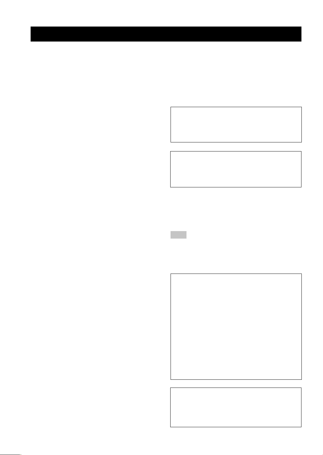
CHECKING THE ACCESSORIES
Check your package to make sure it contains the following items.
Remote control
Batteries
(AAA, R03, UM-4)
Power cable
Non-skid pads
(3 sets: 24 pieces)
1
3
2
Screws
(2 pieces)
Optical cable Audio pin cable
AC adaptor
(LSE9802B1540)
Stand
(for the amplifier unit)
INPUT
MODE
REAR
MUTE
TEST
S.WOOFER
VOLUME
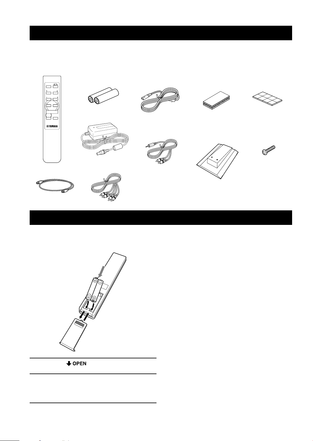
INSTALLING BATTERIES IN THE REMOTE CONTROL
3.5 mm stereo mini/
RCA stereo pin cable
Fastener (1 set)
(for the center speaker)
Insert the batteries in the correct direction by aligning the
+ and – marks on the batteries with the polarity markings
(+ and –) inside the battery compartment.
1 Press the part and slide off the
battery compartment cover.
2 Insert the two batteries (AAA, R03, UM-4
type) with + and – oriented properly.
The batteries can be set only from the direction
shown in the figure.
3 Slide the cover back on so that it snaps into
place.
■ Notes on batteries
• Change all of the batteries if you notice a decrease in
the operating range of the remote control.
• Do not use old batteries together with new ones.
• Do not use different types of batteries (such as alkaline
and manganese batteries) together. Read the packaging
carefully as these different types of batteries may have
the same shape and color.
• If the batteries have leaked, dispose of them
immediately. Avoid touching the leaked material or
letting it come into contact with clothing, etc. Clean the
battery compartment thoroughly before installing new
batteries.
3
English
PREPARATION
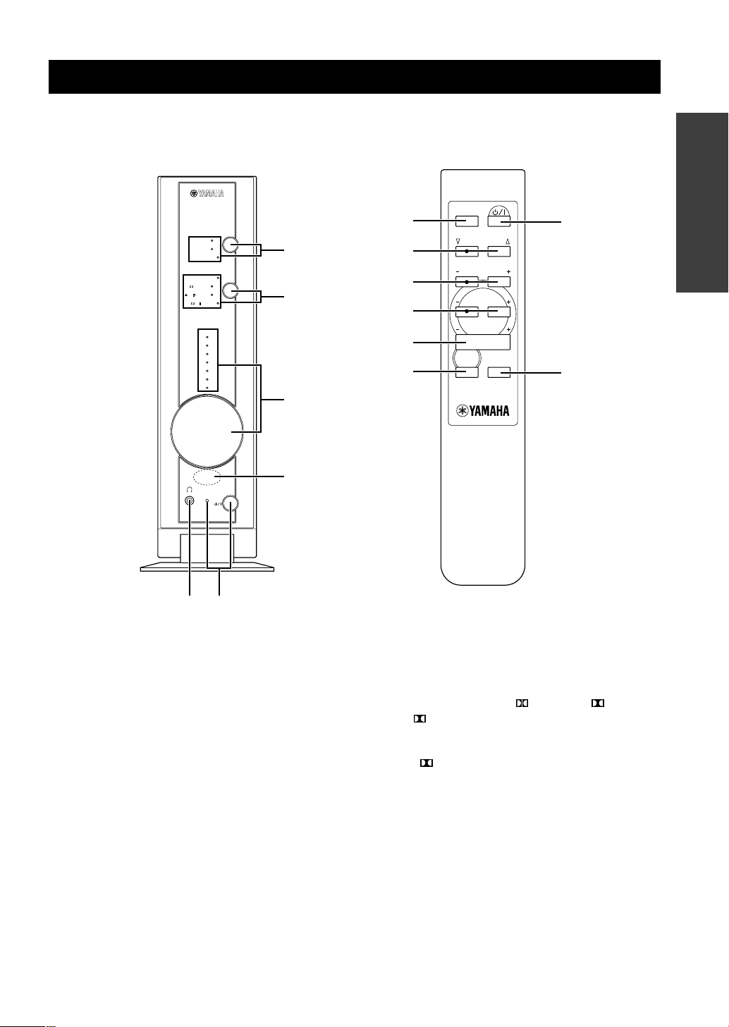
CONTROLS AND FUNCTIONS
1 INPUT and indicators
Press this button repeatedly to select an input source
between DIGITAL 1, DIGITAL 2 and ANALOG. The
current mode is shown by the lighting of the
corresponding indicator.
DIGITAL 1:
Select this to reproduce source signals received at the
DIGITAL INPUTS OPTICAL 1 terminal on the rear
panel.
DIGITAL 2:
Select this to reproduce source signals received at the
DIGITAL INPUTS OPTICAL 2 terminal on the rear
panel.
ANALOG:
Select this to reproduce source signals received at the
ANALOG INPUTS terminals on the rear panel.
2 MODE (k/n) and indicators
Press this button (or k/n) repeatedly to select the desired
surround mode among DTS,
DIGITAL, PLII
MOVIE,
PLII MUSIC and “off”. The current mode is
shown by the lighting of the corresponding indicator.
* If a DTS or Dolby Digital encoded signal is inputted when
DTS or
DIGITAL mode is not selected, the
corresponding indicator lights up dimly.
Refer to page 13 for details on each surround modes.
SILENT
DIGITAL 1
DIGITAL 2
ANALOG
DTS
INPUT
MODE
VOLUME
DIGITAL
7
6
5
4
3
2
1
+6
+4
+2
0
–2
–4
–6
TRIM
PL MOVIE
PL
MUSIC
STANDBY/ON
6 5
2
4
3
1
INPUT
MODE
REAR
MUTE
TEST
S.WOOFER
VOLUME
1
2
7
8
3
9
5
0
Front panel
Remote control
4
CONTROLS AND FUNCTIONS
■ Using the remote control
Handling the remote control
• Do not spill water or other liquids on the remote
control.
• Do not drop the remote control.
• Do not leave or store the remote control in the
following types of conditions:
– high humidity or temperature such as near a heater,
stove or bath;
– dusty places; or
– in places subject to extremely low temperatures.
3 VOLUME (+/–) and indicators
Used for adjusting the overall volume level of this system.
The current level is shown by the lighting of the
indicators on the front panel.
VOLUME on the front panel:
Turn this control clockwise to increase the level, and
counterclockwise to decrease the level.
VOLUME +/– on the remote control:
Press + to increase the level, and – to decrease the level.
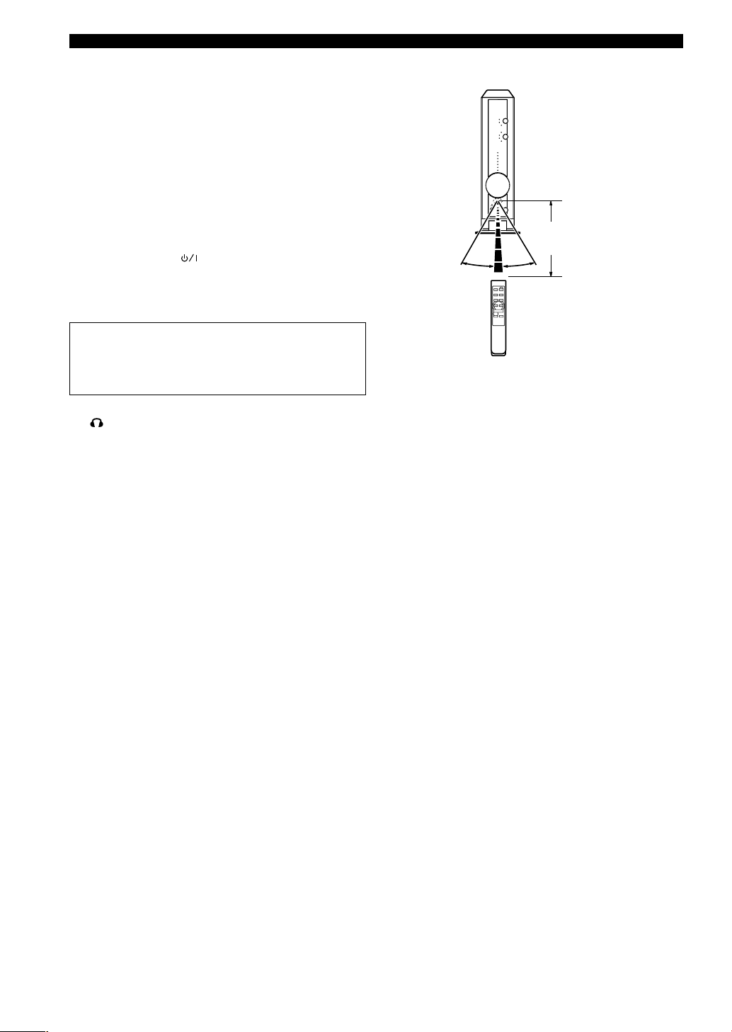
4 Remote control sensor
Receives signals from the remote control.
5 STANDBY/ON (
) and indicator
Each press of this button changes the status of this system
between standby mode and power on. When the power is
on, the indicator lights up.
Standby mode
In this mode, this system will consume a small amount
of power in order to receive infrared-signals from the
remote control.
6
SILENT
Stereo headphones can be connected to this mini-jack for
private listening. Sound output from the speakers is cut
off when headphones are connected to this jack.
7 REAR +/–
These buttons are used for adjusting the sound level from
the rear speakers. Press + to increase the level, and – to
decrease the level.
8 S.WOOFER +/–
These buttons are used for adjusting the sound level from
the subwoofer. Press + to increase the level, and – to
decrease the level.
9 MUTE
Press this button to cut off sound output temporarily.
Press this button again to restore sound output.
0 TEST
Press this button to reproduce a test tone from the
speakers. A test tone is reproduced from each speaker in
turn. The test tone is used for adjusting volume balance
among all the speakers. The adjustment is made by
pressing VOLUME +/– on the remote control.
SILENT
30° 30°
Approximately 6 m (20 feet)
* The STANDBY/ON indicator
flashes while the amplifier
unit is receiving signals from
the remote control.
5
English
PREPARATION
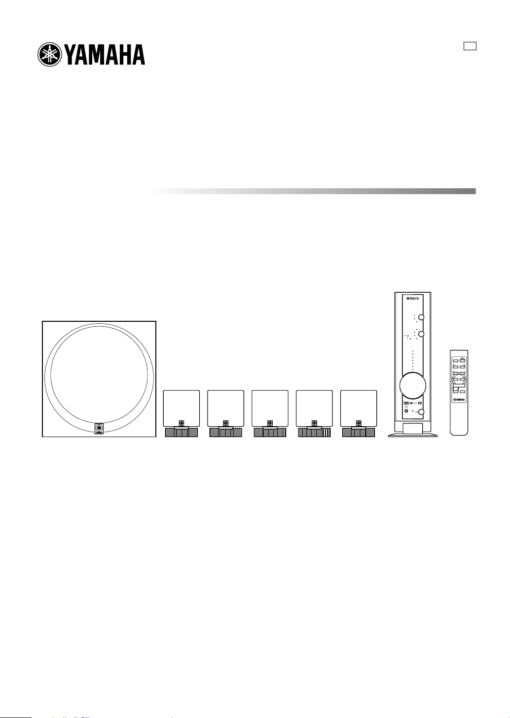
System configuration
This system includes an amplifier unit, five speakers and
a subwoofer.
The three speakers with a 3 m cable are used as front
speakers and a center speaker.
The two speakers with a 10 m cable are used as rear
speakers.
The role of respective speakers
The front speakers are used for reproducing main channel
sound. The rear speakers are used for effect sounds, and
the center speaker is for center channel sound (dialog
etc.).
The subwoofer is used for reproducing sounds of low
frequencies from the front, center and rear surround
channels. The subwoofer also reproduces sounds of the
subwoofer channel when a DTS or Dolby Digital encoded
source is played.
Amplifier
unit
Subwoofer
Right front
speaker
Left front
speaker
Right rear
speaker
Left rear
speaker
Center
speaker
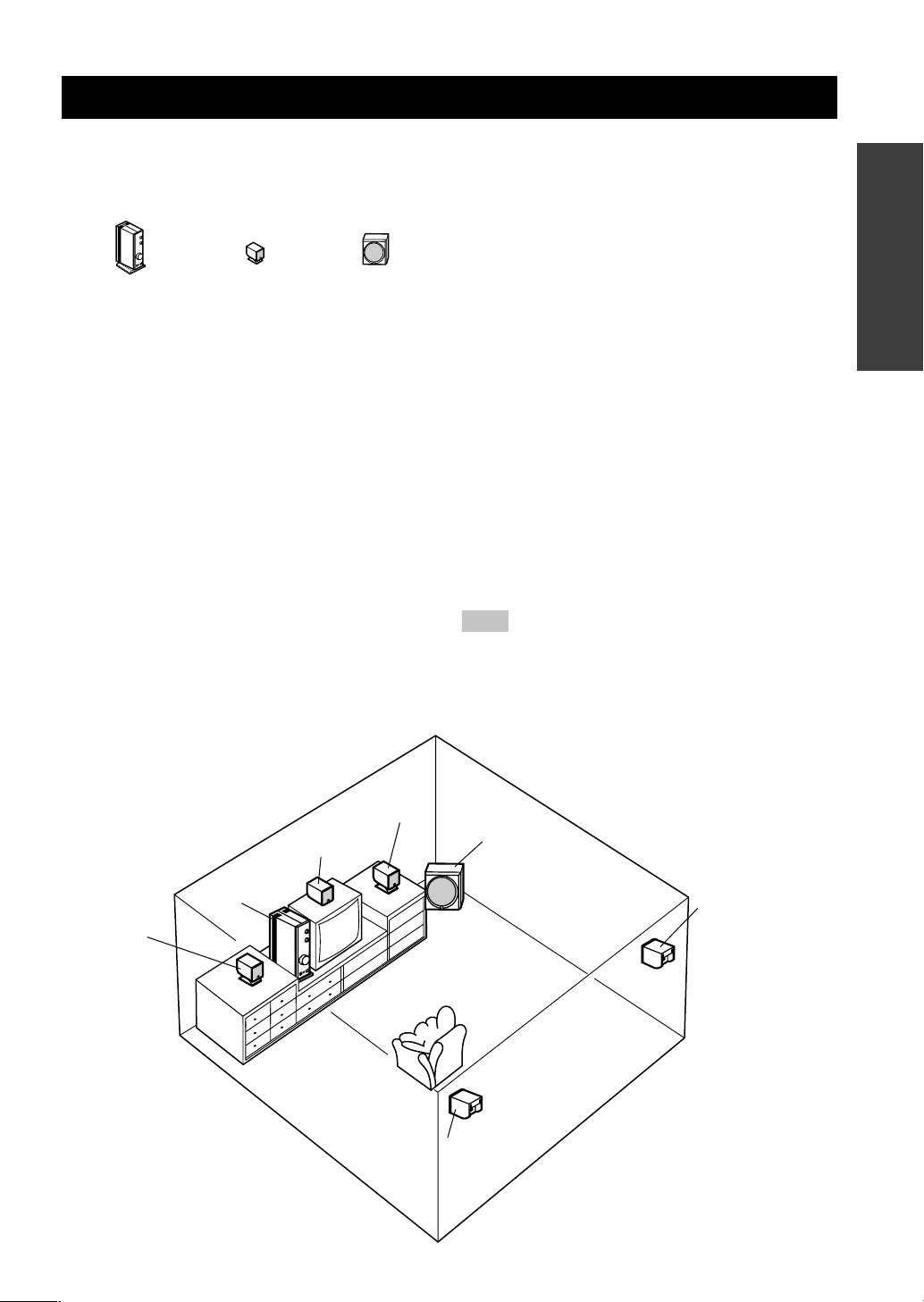
Recommended speaker placement
Before making connections, place all speakers in their
respective positions. The positioning of the speakers is
important because it controls the overall sound quality of
this system.
Place the speakers depending on your listening position
by following the instructions below.
* The front/center/rear speakers can be mounted on a wall. (See
the next page.)
Front speakers: On both sides of and at approximately
the same height as the TV.
Rear speakers: Behind your listening position or on
both sides of the listening room.
Center speaker: Precisely between the front speakers.
* The center speaker can be mounted
on the monitor as shown on the next
page.
Subwoofer: On the floor. The position of the
subwoofer is not so critical because
low bass tones are not highly
directional.
Note
• Although the speaker system in this system is magnetically
shielded, it may still affect the color on the television monitor
when using this system near the television. Adjust the relative
positions of this system and the television if this happens.
SETTING UP THE SYSTEM
Amplifier unit x 1 Speaker x 5 Subwoofer x 1
 Loading...