

Yamaha Audio SREV1 User Manual
SAMPLING REVERBERATOR
Owner’s Manual
MEMORY CARD
Keep This Manual For Future Reference.
INPUT OUTPUT
12 123CH434
CLIP
SIGNAL
CD-ROM
FS LOCK
48K
44.1K
POWER
ON OFF
E
1. IMPORTANT NOTICE: DO NOT MODIFY THIS UNIT! This product, when installed as indicated in the instructions contained in this manual, meets FCC
Laser Diode Properties
* Material : GaAlAs
* Wavelength : 765–815nm
* Emission Duration : Continuous
* Laser Output Power : Less than 0.22mW
Laser output is measured at a
distance of 20cm from the object
lens on the optical pick-up head.
(Note)
This unit is classified as a
Class 1 laser product.
This label is located on the
rear panel.
CLASS 1 LASER PRODUCT
LASER KLASSE 1 PRODUKT
LUOKAN 1 LASERLAITE
KLASS 1 LASERAPPARAT
Klassmärkning för Finland.
CAUTION
USE OF CONTROLS OR ADJUSTMENTS OR
PERFORMANCE OF PROCEDURES OTHER
THAN THOSE SPECIFIED HEREIN MAY RESULT
IN HAZARDOUS RADIATION EXPOSURE.
ATTENTION
TOUTE MANIPULATION DES COMMANDES,
TOUT RÉGLAGE OU TOUTE UTILISATION
AUTRES QUE CEUX SPÉCIFIÉS DANS CE
MANUEL POURRAIENT ENTRAÎNER UNE
EXPOSITION DANGEREUSE AUX RADIATIONS
.
VORSICHT
DIE VERWENDUNG DER BEDIENELEMENTE
UND EINSTELLFUNKTIONEN BZW. DAS
AUSFÜHREN VON HANDLUNGEN IN EINER
NICHT AUSDRÜCKLICH IN DIESER
ANLEITUNG ERWAHNTEN WEISE KÖNNEN ZU
EINER GESUNDHEITSSCHADLICHEN
BESTRAHLUNG FÜHREN
.
PRECAUCIÓN
EL USO DE CONTROLES, AJUSTES O LA
APLICACIÓN DE PROCEDIMIENTOS
DISTINTOS A LOS DESCRITOS EN ESTE
MANUAL, PUEDE OCASIONAR UNA
EXPOSICIÓN A RADIACIÓN PELIGROSA
.
requirements. Modifications not expressly approved by Yamaha may void your authority, granted by the FCC, to use the product.
2. IMPORTANT: When connecting this product to accessories and/or another product use only high quality shielded cables. Cable/s supplied with this product MUST
be used. Follow all installation instructions. Failure to follow instructions could void your FCC authorization to use this product in the USA.
3. NOTE: This product has been tested and found to comply with the requirements listed in FCC Regulations, Part 15 for Class “B” digital devices. Compliance with
these requirements provides a reasonable level of assurance that your use of this product in a residential environment will not result in harmful interference with
other electronic devices. This equipment generates/uses radio frequencies and, if not installed and used according to the instructions found in the users manual, may
cause interference harmful to the operation of other electronic devices. Compliance with FCC regulations does not guarantee that interference will not occur in all
installations. If this product is found to be the source of interference, which can be determined by turning the unit “OFF” and “ON”, please try to eliminate the
problem by using one of the following measures: Relocate either this product or the device that is being affected by the interference. Utilize power outlets that are on
different branch (circuit breaker or fuse) circuits or install AC line filter/s. In the case of radio or TV interference, relocate/reorient the antenna. If the antenna lead-in
is 300 ohm ribbon lead, change the lead-in to coaxial type cable. If these corrective measures do not produce satisfactory results, please contact the local retailer
authorized to distribute this type of product. If you can not locate the appropriate retailer, please contact Yamaha Corporation of America, Electronic Service
Division, 6600 Orangethorpe Ave, Buena Park, CA 90620
The above statements apply ONLY to those products distributed by Yamaha Corporation of America or its subsidiaries.
WARNING: THIS APPARATUS MUST BE EARTHED
IMPORTANT
THE WIRES IN THIS MAINS LEAD ARE COLOURED IN
ACCORDANCE WITH THE FOLLOWING CODE:
GREEN-AND-YELLOW : EARTH
BLUE : NEUTRAL
BROWN : LIVE
As the colours of the wires in the mains lead of this apparatus may
not correspond with the coloured markings identifying the terminals in
your plug, proceed as follows:
The wire which is coloured GREEN and YELLOW must be
connected to the terminal in the plug which is marked by the letter E
or by the safety earth symbol or coloured GREEN and YELLOW.
The wire which is coloured BLUE must be connected to the terminal
which is marked with the letter N or coloured BLACK.
The wire which is coloured BROWN must be connected to the
terminal which is marked with the letter L or coloured RED.
* This applies only to products distributed by YAMAHA KEMBLE
MUSIC (U.K.) LTD.
FCC INFORMATION (U.S.A.)
ADVARSEL!
Lithiumbatteri—Eksplosionsfare ved fejlagtig
håndtering. Udskiftning må kun ske med batteri
af samme fabrikat og type. Levér det brugte
batteri tilbage til leverandoren.
VARNING
Explosionsfara vid felaktigt batteribyte. Använd
samma batterityp eller en ekvivalent typ som
rekommenderas av apparattillverkaren.
Kassera använt batteri enligt fabrikantens
instruktion.
VAROITUS
Paristo voi räjähtää, jos se on virheellisesti
asennettu. Vaihda paristo ainoastaan
laitevalmistajan suosittelemaan tyyppiin. Hävitä
käytetty paristo valmistajan ohjeiden
mukaisesti.

Important Information
Important Information
Read the following before using the SREV1
Warnings
• Do not subject the unit to extreme temperatures, humidity, direct sunlight, or dust,
which could be a potential fire or electrical shock hazard.
• Do not allow water to enter the unit or allow it to get wet. Fire or electrical shock may
result.
• Connect the power cord or AC adapter only to an AC outlet of the type stated in this
Owner’s Manual or as marked on the unit. Failure to do so is a fire and electrical shock
hazard.
• Hold the power-cord plug or AC adapter when disconnecting from an AC outlet. Never
pull the cord. A power cord damaged through pulling is a potential fire and electrical
shock hazard.
• Do not touch the power plug or AC adapter with wet hands. Doing so is a potential electrical shock hazard.
• Do not place heavy objects, including the unit, on top of the power cord. A damaged
power cord is a fire and electrical shock hazard. In particular, be careful not to place
heavy objects on a power cord covered by a carpet.
• Do not place a container with liquid or small metal objects on top of this unit. Liquid
or metal objects inside this unit are a fire and electrical shock hazard.
• Do not scratch, bend, twist, pull, or heat the power cord. A damaged power cord is a
fire and electrical shock hazard.
i
• If the power cord is damaged (e.g., cut or a bare wire is exposed), ask your dealer for a
replacement. Using the unit with a damaged power cord is a fire and electrical shock
hazard.
• Do not plug several pieces of equipment into the same AC outlet. This may overload
the AC outlet, and could be a fire or electrical shock hazard. It may also affect the performance of some equipment.
• If you notice any abnormality, such as smoke, odor, or noise, or if a foreign object or
liquid gets inside the unit, turn it off immediately. Remove the power cord or AC
adapter from the AC outlet and consult your dealer for repair. Using a unit in this condition is a fire and electrical shock hazard.
• Do not place small objects on top of the unit. Metal objects falling inside is a fire and
electrical shock hazard.
• If a foreign object or water gets inside the unit, turn it off immediately. Remove the
power cord or AC adapter from the AC outlet and consult your dealer for repair. Using
a unit in this condition is a potential fire and electrical shock hazard.
• If the unit is dropped or the cabinet damaged, turn off the power, remove the power
plug or AC adapter from the AC outlet, and contact your dealer. If you continue using
the unit without heeding this instruction, fire or electrical shock may result.
• Do not remove the unit covers. You could receive an electrical shock. If you think internal inspection, maintenance, or repair is necessary, contact your dealer.
• Do not attempt to modify the unit. This is a potential fire and electrical shock hazard.
SREV1—Owner’s Manual

ii
Important Information
• Do not block the front panel air inlet, ventilation slots, or fan outlets. Doing so is a
potential fire hazard.
Cautions
• Allow enough free space around the SREV1 for normal ventilation. This should be 20
cm behind, 10 cm at the sides, and 30 cm above. These distances should also be adopted
when rack-mounting the SREV1. If the SREV1 is mounted in a portable rack case, keep
the rear of the case open when using the SREV1 so as not to obstruct the flow of air from
the two cooling fans. If the airflow is not adequate, the SREV1 will heat up inside and
may cause a fire. Do not mount the SREV1 above equipment that produces a lot of heat,
such as a power amplifier.
• Turn off all audio equipment when connecting to the unit, and use only cables of the
type specified in this
• If you plan not to use the unit for a long period of time, remove the power cord or AC
adapter from the AC outlet. Leaving the unit connected is a potential fire hazard.
• Do not use benzene, thinner, cleaning detergent, or a chemical cloth to clean the unit.
Use only a soft, dry cloth.
• If the unit is stored in a cold place (e.g., overnight in a car), and then moved to a warmer
environment, or if the temperature rises sharply, condensation may form inside the
unit, which may affect performance. In this case, the unit should be allowed to acclimatize for about one hour before use.
• When the wordclock is changed on the wordclock master device, noise may occur from
the SREV1’s outputs, especially if an MY8-AT I/O card is installed, so turn down your
power amps beforehand, otherwise any connected speakers may be damaged.
Owner’s Manual.
• If the RC-SREV1 displays the message “LOW BATTERY” when you turn on the unit,
ask your Yamaha dealer to replace the internal battery as soon as possible. The unit will
still work, but data other than backed up data will be lost. We recommend that you save
this data to a PC Card before replacing the battery.
• For electrical safety reasons, it’s important that the SREV1 is grounded properly. The
supplied power cord has a three-pin plug, and if the ground terminal of the AC outlet
is grounded, then the SREV1 will be grounded sufficiently through the power cord. If
the AC outlet does not provide a suitable ground, however, a ground connection should
be made to the dedicated grounding screw.
SREV1—Owner’s Manual

Important Information
iii
Handling CD-ROMs
• Use only discs of the type specified in this Owner’s Manual .
• The CD-ROM drive is for use with data discs only. Never insert audio CDs.
• Store discs in a place free from extreme temperatures, humidity, dust, and dirt.
• Always store discs in their cases.
• When handling discs, be careful not to touch the surface. Hold discs by the edge. Fingerprints, smudges, scratches, or dirt can affect performance.
• Be careful not to scratch the labeled side of the disc. Even scratches on that side can
affect performance.
• Fingerprints and dust should be removed by wiping gently from the center of the disc
towards the disc edge, using a soft, dry cloth. Never wipe in a circular motion and never
rub a disc hard with a dry cloth.
• For stubborn stains and dirt, use a cleaning kit designed specifically for use with CDs.
Do not use benzene, thinner, cleaning detergent, or a chemical cloth.
• For disc marking, use only pens specifically designed for writing on CDs and write only
on the designated area. Do not attach a label to a disc.
• If a disc is stored in a cold place (e.g., overnight in a car), and then moved to a warmer
environment, or if the temperature rises sharply, condensation may form on the disc
surface, which may affect performance. In this case, the disc should be allowed to acclimatize for about one hour before use.
• Do not under any circumstances attempt to use discs that are cracked or warped. Doing
so may seriously damage the unit.
Handling PC Cards
• Use only PC Cards of the type specified in this Owner’s Manual .
• Some PC Cards and PC Card adapters cannot be used with the SREV1.
• Do not eject a PC Card while the activity indicator is lit. Doing so may cause data lose.
• Store PC Cards in a place free from extreme temperatures, humidity, dust, and dirt.
• Always store PC Cards in their cases.
Precautions for Transportation
During transportation, keep the CD-ROM door shut with tape, or a pad, or the like.
• When using tape, use tape that adheres well to the front panel.
• When using a pad, use a pad stiff enough that the elasticity holds the tray in place.
Front panel
Pad
Tape
CD-ROM door
SREV1—Owner’s Manual

iv
Important Information
Interference
The SREV1 uses high-frequency digital circuits that may cause interference on radio
and television equipment located nearby. If interference is a problem, relocate the
affected equipment.
SREV1 Exclusion of Certain Responsibility
Manufacturer, importer, or dealer shall not be liable for any incidental damages including personal injury or any other damages caused by improper use or operation of the
SREV1.
Package Contents
The SREV1 package contains the following items:
• SREV1 Sampling Reverberator
• CD-ROM containing preset reverb programs and SREV1 utilities
•Power cord
• This
Owner’s Manual
Contact your Yamaha dealer if something is missing.
Optional Extras
• RC-SREV1 Remote Controller
• DB-SREV1 DSP Expansion Board
Trademarks
ADAT MultiChannel Optical Digital Interface is a trademark and ADAT and Alesis are
registered trademarks of Alesis Corporation. Intel and Pentium are registered trademarks and MMX is a trademark of Intel Corporation. PCMCIA is a registered trademark of the Personal Computer Memory Card International Association. Tascam
Digital Interface is a trademark and Tascam and Teac are registered trademarks of Teac
Corporation. Windows is a trademark of Microsoft Corporation. Yamaha is a trademark of Yamaha Corporation. All other trademarks are the property of their respective
holders and are hereby acknowledged.
Copyright
No part of the SREV1, its software, including the supplied impulse-response data, or
this
Owner’s Manual
without the prior written authorization of Yamaha Corporation. Using the supplied
impulse-response data with equipment other than the SREV1, or obtaining the data by
sampling or any other means, is strictly prohibited.
may be reproduced or distributed in any form or by any means
© 2000 Yamaha Corporation. All rights reserved.
Yamaha Web Site
Information about the SREV1, related products, and other Yamaha professional audio
equipment is available on the Yamaha Professional Audio Web site at:
<http://www.yamaha.co.jp/product/proaudio/homeenglish/>.
SREV1—Owner’s Manual

Important Information
About this Manual
This Owner’s Manual covers both the SREV1 Sampling Reverberator and the optional
RC-SREV1 Remote Controller. (The SREV1 software manuals are on the CD-ROM.)
All the information you need in order to operate the SREV1 Sampling Reverberator
and the optional RC-SREV1 Remote Controller is contained in this manual. Use the
table of contents to familiarize yourself with its organization and locate topics, and use
the index to locate specific information. A glossary of SREV1-related jargon is provided
on page 93.
Installing the SREV1
When mounting the SREV1 in a rack, remove its feet and leave adequate ventilation
space all around (at least 20 cm of free space behind). If the SREV1 is mounted in a portable rack case, keep the rear of the case open when using the SREV1 so as not to
obstruct the flow of air from the two cooling fans. Do not mount the SREV1 above
equipment that produces a lot of heat, such as a power amplifier.
Conventions Used in this Manual
v
In this manual, the SREV1 Sampling Reverberator, the optional RC-SREV1 Remote
Controller, and the SREV1 software are referred to as the “SREV1,” “RC-SREV1,” and
“SREV1 software” respectively.
The RC-SREV1 features two types of button: physical buttons that you can press (e.g.,
ENTER and UTILITY) and buttons that appear on the RC-SREV1 display pages. References to physical buttons are enclosed in square brackets, such as “press the [ENTER]
button.” References to page buttons are not emphasized, for example, select the WCLK
IN button.
Generally there are three versions of each RC-SREV1 display page, one for each mode:
2-channel, 4-channel, and 2-channel x2. If relevant to the task being explained, all three
pages are shown. If the item being discussed is the same regardless of which mode is
selected, then only one page is shown.
“PC” refers to an IBM PC-compatible computer running a Windows operating system.
SREV1—Owner’s Manual

vi
Important Information
NEDERLAND THE NETHERLANDS
● Dit apparaat bevat een lithium batterij voor geheugen
back-up.
● Raadpleeg uw leverancier over de verwijdering van de
batterij op het moment dat u het apparaat ann het einde
van de levensduur afdankt of de volgende Yamaha Service
Afdeiing:
Yamaha Music Nederland Service Afdeiing
Kanaalweg 18-G, 3526 KL UTRECHT
Tel. 030-2828425
● Gooi de batterij niet weg, maar lever hem in als KCA.
● This apparatus contains a lithium battery for memory
back-up.
● For the removal of the battery at the moment of the
disposal at the end of the service life please consult your
retailer or Yamaha Service Center as follows:
Yamaha Music Nederland Service Center
Address: Kanaalweg 18-G, 3526 KL
UTRECHT
Tel: 030-2828425
● Do not throw away the battery. Instead, hand it in as small
chemical waste.
SREV1—Owner’s Manual

Contents
Contents
1 Welcome . . . . . . . . . . . . . . . . . . . . . . . . . . . . . . . . . 1
Welcome to the SREV1 . . . . . . . . . . . . . . . . . . . . . . . . . . . . . . . . . . . . . . . . . . . . 2
The SREV1 in a Nutshell . . . . . . . . . . . . . . . . . . . . . . . . . . . . . . . . . . . . . . . . . . . 2
SREV1 Features . . . . . . . . . . . . . . . . . . . . . . . . . . . . . . . . . . . . . . . . . . . . . . . . . . . 4
SREV1 Basics . . . . . . . . . . . . . . . . . . . . . . . . . . . . . . . . . . . . . . . . . . . . . . . . . . . . . 6
SREV1 Block Diagram . . . . . . . . . . . . . . . . . . . . . . . . . . . . . . . . . . . . . . . . . . . . 10
2 Touring the SREV1 & RC-SREV1 . . . . . . . . . . . . . . 11
SREV1 Front Panel . . . . . . . . . . . . . . . . . . . . . . . . . . . . . . . . . . . . . . . . . . . . . . . 12
SREV1 Rear Panel . . . . . . . . . . . . . . . . . . . . . . . . . . . . . . . . . . . . . . . . . . . . . . . . 14
RC-SREV1 Control Surface . . . . . . . . . . . . . . . . . . . . . . . . . . . . . . . . . . . . . . . . 16
RC-SREV1 Display . . . . . . . . . . . . . . . . . . . . . . . . . . . . . . . . . . . . . . . . . . . . . . . 18
RC-SREV1 Rear Panel . . . . . . . . . . . . . . . . . . . . . . . . . . . . . . . . . . . . . . . . . . . . 20
3 Getting Started . . . . . . . . . . . . . . . . . . . . . . . . . . . 21
First Steps . . . . . . . . . . . . . . . . . . . . . . . . . . . . . . . . . . . . . . . . . . . . . . . . . . . . . . 22
Connecting the RC-SREV1 Remote Controller . . . . . . . . . . . . . . . . . . . . . . . . 22
Hookup Examples . . . . . . . . . . . . . . . . . . . . . . . . . . . . . . . . . . . . . . . . . . . . . . . 23
Connecting the Power Cord . . . . . . . . . . . . . . . . . . . . . . . . . . . . . . . . . . . . . . . 26
Turning On & Off the SREV1 . . . . . . . . . . . . . . . . . . . . . . . . . . . . . . . . . . . . . . 26
Turning On & Off the RC-SREV1 . . . . . . . . . . . . . . . . . . . . . . . . . . . . . . . . . . 26
Using an Optional RC-SREV1 AC Adapter . . . . . . . . . . . . . . . . . . . . . . . . . . . 27
Adjusting the RC-SREV1 Brightness & Contrast . . . . . . . . . . . . . . . . . . . . . . 27
Using CD-ROMs . . . . . . . . . . . . . . . . . . . . . . . . . . . . . . . . . . . . . . . . . . . . . . . . 28
Using PC Cards . . . . . . . . . . . . . . . . . . . . . . . . . . . . . . . . . . . . . . . . . . . . . . . . . . 29
vii
4 Basic Operation . . . . . . . . . . . . . . . . . . . . . . . . . . . 31
SREV1 Startup . . . . . . . . . . . . . . . . . . . . . . . . . . . . . . . . . . . . . . . . . . . . . . . . . . 32
RC-SREV1 Startup . . . . . . . . . . . . . . . . . . . . . . . . . . . . . . . . . . . . . . . . . . . . . . . 32
About the Internal Operations at Startup . . . . . . . . . . . . . . . . . . . . . . . . . . . . 33
Selecting Reverb Modes . . . . . . . . . . . . . . . . . . . . . . . . . . . . . . . . . . . . . . . . . . . 34
Assigning Inputs . . . . . . . . . . . . . . . . . . . . . . . . . . . . . . . . . . . . . . . . . . . . . . . . . 35
Setting Input & Output Levels . . . . . . . . . . . . . . . . . . . . . . . . . . . . . . . . . . . . . 36
Metering . . . . . . . . . . . . . . . . . . . . . . . . . . . . . . . . . . . . . . . . . . . . . . . . . . . . . . . 37
Setting the Meter Mode . . . . . . . . . . . . . . . . . . . . . . . . . . . . . . . . . . . . . . . . . . . 39
Using Peak Hold . . . . . . . . . . . . . . . . . . . . . . . . . . . . . . . . . . . . . . . . . . . . . . . . . 39
Bypassing the SREV1 . . . . . . . . . . . . . . . . . . . . . . . . . . . . . . . . . . . . . . . . . . . . . 40
Setting the Bypass Mode . . . . . . . . . . . . . . . . . . . . . . . . . . . . . . . . . . . . . . . . . . 40
Using the Title Edit dialog Box . . . . . . . . . . . . . . . . . . . . . . . . . . . . . . . . . . . . . 41
Working with Quick Memories . . . . . . . . . . . . . . . . . . . . . . . . . . . . . . . . . . . . 42
Working with the Library . . . . . . . . . . . . . . . . . . . . . . . . . . . . . . . . . . . . . . . . . 45
Working with Projects . . . . . . . . . . . . . . . . . . . . . . . . . . . . . . . . . . . . . . . . . . . . 48
5 Editing Programs . . . . . . . . . . . . . . . . . . . . . . . . . . 51
Main 1 Parameters . . . . . . . . . . . . . . . . . . . . . . . . . . . . . . . . . . . . . . . . . . . . . . . 52
Main 2 Parameters . . . . . . . . . . . . . . . . . . . . . . . . . . . . . . . . . . . . . . . . . . . . . . . 54
Fine Reverb Parameters . . . . . . . . . . . . . . . . . . . . . . . . . . . . . . . . . . . . . . . . . . . 56
Pre EQ . . . . . . . . . . . . . . . . . . . . . . . . . . . . . . . . . . . . . . . . . . . . . . . . . . . . . . . . . 57
Post EQ . . . . . . . . . . . . . . . . . . . . . . . . . . . . . . . . . . . . . . . . . . . . . . . . . . . . . . . . 59
Loading Impulse-Response Data . . . . . . . . . . . . . . . . . . . . . . . . . . . . . . . . . . . 61
SREV1—Owner’s Manual

viii
Contents
6 Multiple SREV1s . . . . . . . . . . . . . . . . . . . . . . . . . . . 63
About Multiple SREV1s . . . . . . . . . . . . . . . . . . . . . . . . . . . . . . . . . . . . . . . . . . . 64
Connections . . . . . . . . . . . . . . . . . . . . . . . . . . . . . . . . . . . . . . . . . . . . . . . . . . . . . 64
Multiple-unit Hookup with the RC-SREV1 . . . . . . . . . . . . . . . . . . . . . . . . . . . 64
Multiple-unit Operating Notes . . . . . . . . . . . . . . . . . . . . . . . . . . . . . . . . . . . . . 65
Selecting SREV1s from the RC-SREV1 . . . . . . . . . . . . . . . . . . . . . . . . . . . . . . . 65
7 MIDI . . . . . . . . . . . . . . . . . . . . . . . . . . . . . . . . . . . . 67
MIDI & the SREV1 . . . . . . . . . . . . . . . . . . . . . . . . . . . . . . . . . . . . . . . . . . . . . . . 68
MIDI Ports . . . . . . . . . . . . . . . . . . . . . . . . . . . . . . . . . . . . . . . . . . . . . . . . . . . . . . 68
MIDI Pages . . . . . . . . . . . . . . . . . . . . . . . . . . . . . . . . . . . . . . . . . . . . . . . . . . . . . . 69
Setting the MIDI Receive Channels . . . . . . . . . . . . . . . . . . . . . . . . . . . . . . . . . . 69
Assigning Quick Memory Programs to Program Changes . . . . . . . . . . . . . . . 70
Assigning Parameters to Control Changes . . . . . . . . . . . . . . . . . . . . . . . . . . . . 71
8 Wordclocks . . . . . . . . . . . . . . . . . . . . . . . . . . . . . . . 73
Wordclocks & the SREV1 . . . . . . . . . . . . . . . . . . . . . . . . . . . . . . . . . . . . . . . . . . 74
Wordclock Connections . . . . . . . . . . . . . . . . . . . . . . . . . . . . . . . . . . . . . . . . . . . 74
Selecting the Wordclock Source . . . . . . . . . . . . . . . . . . . . . . . . . . . . . . . . . . . . . 75
Wordclock Hookup Examples . . . . . . . . . . . . . . . . . . . . . . . . . . . . . . . . . . . . . . 78
9 I/O Options . . . . . . . . . . . . . . . . . . . . . . . . . . . . . . . 81
I/O Options & the SREV1 . . . . . . . . . . . . . . . . . . . . . . . . . . . . . . . . . . . . . . . . . . 82
Available I/O Cards . . . . . . . . . . . . . . . . . . . . . . . . . . . . . . . . . . . . . . . . . . . . . . . 82
Choosing I/O Cards . . . . . . . . . . . . . . . . . . . . . . . . . . . . . . . . . . . . . . . . . . . . . . 83
Installing I/O Cards . . . . . . . . . . . . . . . . . . . . . . . . . . . . . . . . . . . . . . . . . . . . . . . 84
Troubleshooting . . . . . . . . . . . . . . . . . . . . . . . . . . . . . . 85
Appendix . . . . . . . . . . . . . . . . . . . . . . . . . . . . . . . . . . . 87
Error Messages . . . . . . . . . . . . . . . . . . . . . . . . . . . . . . . . . . . . . . . . . . . . . . . . . . . 87
Confirmation Messages . . . . . . . . . . . . . . . . . . . . . . . . . . . . . . . . . . . . . . . . . . . 88
General Messages . . . . . . . . . . . . . . . . . . . . . . . . . . . . . . . . . . . . . . . . . . . . . . . . . 89
General Specifications . . . . . . . . . . . . . . . . . . . . . . . . . . . . . . . . . . . . . . . . . . . . . 90
Digital Input Specifications . . . . . . . . . . . . . . . . . . . . . . . . . . . . . . . . . . . . . . . . 91
Digital Output Specifications . . . . . . . . . . . . . . . . . . . . . . . . . . . . . . . . . . . . . . . 91
Control I/O Specifications . . . . . . . . . . . . . . . . . . . . . . . . . . . . . . . . . . . . . . . . . 91
Remote Cable Wiring Diagram . . . . . . . . . . . . . . . . . . . . . . . . . . . . . . . . . . . . . 91
Dimensions . . . . . . . . . . . . . . . . . . . . . . . . . . . . . . . . . . . . . . . . . . . . . . . . . . . . . 92
Glossary . . . . . . . . . . . . . . . . . . . . . . . . . . . . . . . . . . . . 93
Index . . . . . . . . . . . . . . . . . . . . . . . . . . . . . . . . . . . . . . . 95
MIDI Implementation Chart
SREV1—Owner’s Manual

In this chapter...
Welcome
Welcome
1
1
Welcome to the SREV1 . . . . . . . . . . . . . . . . . . . . . . . . . . . . . . . . . . . . . . . . . . . . . 2
The SREV1 in a Nutshell . . . . . . . . . . . . . . . . . . . . . . . . . . . . . . . . . . . . . . . . . . . . 2
SREV1 Features . . . . . . . . . . . . . . . . . . . . . . . . . . . . . . . . . . . . . . . . . . . . . . . . . . . . 4
SREV1 Basics . . . . . . . . . . . . . . . . . . . . . . . . . . . . . . . . . . . . . . . . . . . . . . . . . . . . . . 6
SREV1 Block Diagram . . . . . . . . . . . . . . . . . . . . . . . . . . . . . . . . . . . . . . . . . . . . . 10
SREV1—Owner’s Manual
2
Chapter 1—Welcome
Welcome to the SREV1
Thank you for choosing the Yamaha SREV1 Sampling Reverberator.
Unlike conventional digital reverberators, which synthesize reverberation using contrived signal-processing algorithms, the new SREV1 Sampling Reverberator from
Yamaha employs digital convolution processing to impose an acoustic “fingerprint” of
a previously measured environment onto any audio signal, faithfully recreating the
original reverberation, with accurate reflection detail identical to that produced had the
sound been heard in that environment. The SREV1 is perfect for recording studios,
audio post, broadcast, concert halls, theaters, or anyone looking for superb quality
reverb that sounds just like the real thing, with the option to sample the reverberation
characteristics of any location for use back in the studio.
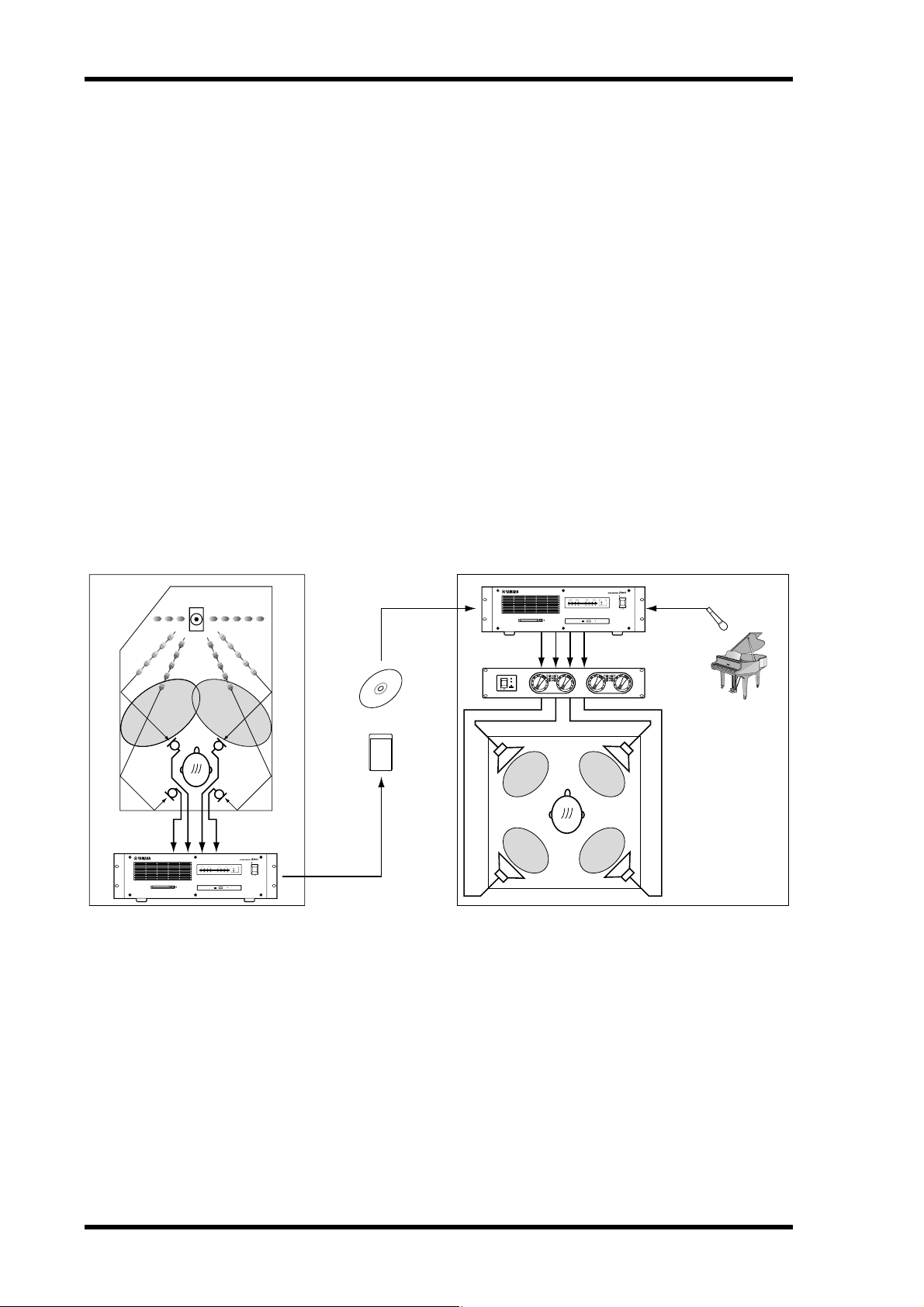
The SREV1 in a Nutshell
Sonic “fingerprints” are produced by measuring the impulse response (i.e., acoustic
characteristics) of an environment, which involves “blasting out” time-stretched pulses
through an accurate speaker system and recording the results via carefully placed
microphones. The resultant impulse-response data can then be used by the SREV1 to
convolve the captured acoustic characteristics onto any audio signal.
Sampling on location Convolution processing
Firing time-stretched pulses
MEMORY CARD
LLR
CLIP
15
20
POWER
25
10
TEMP
LEVEL
PROTECTION
30 30
6
3
40
POWER
ON OFF
0
–dB
12 123CH434
15
20
25
10
6
3
40
0
R
CLIP
SIGNAL
CD-ROM
15
20
25
30 30
40
0
48K
44.1K
ON OFF
LLR
CLIP
15
20
25
10
10
LEVEL
6
6
3
3
40
0
–dB
R
POWER
FS LOCK
INPUT OUTPUT
Impulse-response data
PC ATA CARD
FL FR
RL RR
INPUT OUTPUT
CLIP
12 123CH434
SIGNAL
MEMORY CARD
CD-ROM
POWER
FS LOCK
48K
44.1K
ON OFF
FLASH CARD
In addition to stereo reverb (2-channel mode), the SREV1 offers four-channel processing for surround reverb (4-channel mode). Alternatively, the SREV1 can be configured
as two fully independent reverberators (2-channel x2 mode), each with its own inputs,
outputs, and program settings.
Thirty-two of Yamaha’s new convolution chips provide the necessary “horsepower” for
real-time convolution of up to 5.46 seconds per channel (2-channel mode), 2.73 seconds per channel (4-channel or 2-channel x2 mode). Featuring an additional 32 convolution chips, the optional DB-SREV1 DSP Expansion Board doubles the available
convolution time to a maximum of 10.92 seconds per channel (2-channel mode), 5.46
seconds per channel (4-channel or 2-channel x2 mode).
Measured impulse response data is combined with variable parameters such as reverb
time and initial delay to form reverb
SREV1—Owner’s Manual
programs
, which can be stored in special
Quick

The SREV1 in a Nutshell
memories or the Internal Card or PC Card. Up to six programs can be stored in Quick
memory in 2-channel or 4-channel mode; 12 in 2-channel x2 mode. Programs in
Quick memory can be recalled instantly via the optional RC-SREV1 Remote Controller
or MIDI Program Changes.
Projects, which contain all the Quick memory programs and the current program settings, provide a convenient way to manage programs and settings for each job. Projects
can be stored on the Internal Card or PC Card.
The PC Card slot is fully compatible with the PC Card ATA specification and supports
the FAT16 file system. The CD-ROM drive supports the ISO9660 Level 2 format. Both
the PC Card and CD-ROM format is compatible with Windows.
The supplied CD-ROM contains preset reverb programs of famous venues from
around the world, and a CD-ROM library is planned for future release. The preset programs on the supplied CD-ROM are loaded into the Internal Card at the factory.
Program editing is handled at two levels: Main parameters and Fine parameters. With
Main parameter editing, channel parameters, such as reverb time, initial delay, reverb
balance, EQ, etc., are grouped, so that, for example, the reverb time of all channels can
be set simultaneously. Fine parameter editing adds pre-convolution 4-band PEQ,
post-convolution 4-band PEQ, and impulse-response data loading. Reverb parameters
can be edited individually or grouped. Reverb balance and reverb level parameters for
each channel can be controlled individually via MIDI Control Changes.
Two AES/EBU inputs and outputs (providing 4 channels) are built in and two mini
YGDAI (Yamaha General Digital Audio Interface) slots offer various analog and digital
I/O options (AES/EBU, ADAT, Tascam). Inputs can be assigned to channels individually, allowing various input/output configurations. In 2-channel mode, for example, a
single input can be assigned to both channels (left and right) for mono in/stereo out
operation, or an individual input can be assigned to each channel for true stereo in/stereo out operation.
Superb sonic performance is provided by Yamaha’s new convolution chip, 24-bit I/O,
32-bit internal signal processing, and 48 kHz internal wordclock. External wordclocks
of 44.1 kHz and 48 kHz are supported and can be sourced via the dedicated BNC wordclock input, AES/EBU inputs, or card slot inputs.
3
Up to four SREV1s can be controlled using the optional RC-SREV1 Remote Controller,
which features a large 320 x 240 dot graphical display, with fluorescent backlight and
adjustable brightness and contrast, four motorized faders for parameter editing, and
input and output clip indicators. Power is supplied by the SREV1.
SREV1—Owner’s Manual

4
Chapter 1—Welcome
SREV1 Features
Sonic Performance
• 32 Yamaha convolution chips
• 24-bit I/O and 32-bit internal processing
• 48 kHz internal wordclock
• 44.1 kHz or 48 kHz external wordclock
Reverb Modes & Convolution Times
• 2-channel (stereo), 4-channel (surround), and 2-channel x2 (A and B) reverb modes
• Maximum convolution time of 5.46 seconds per channel (2-channel mode), 2.73 seconds per channel (4-channel mode or 2-channel x2 mode)
• Featuring an additional 32 convolution chips, the optional DB-SREV1 DSP Expansion
Board doubles the available convolution time to a maximum of 10.92 seconds per
channel (2-channel mode), 5.46 seconds per channel (4-channel or 2-channel x2
mode)
Programs & Projects
• Programs combine impulse-response data with variable parameters such as reverb
time, initial delay, EQ, and more
• Quick memories hold six instantly recallable programs (2-channel or 4-channel
mode); 12 programs (2-channel x2 mode)
• Quick memory programs can be recalled via MIDI
• Projects provide a convenient way to manage programs for each job
• Programs and projects can be saved on the Internal Card or PC Card
Storage
• PC Card slot fully compatible with the PC Card ATA specification and supports the
FAT16 file system
• CD-ROM drive supports ISO9660 Level 2 format
• PC Card and CD-ROM formats compatible with Windows
Editing
• Basic editing includes reverb time, initial delay, and reverb balance
• Advanced editing includes basic parameters plus pre-convolution 4-band PEQ,
post-convolution 4-band PEQ, and impulse-response data loading for each channel
• Reverb balance and level parameters can be controlled via MIDI
SREV1—Owner’s Manual

SREV1 Features
Flexible I/O
• Two AES/EBU format inputs and outputs (providing 4 channels)
• Two mini YGDAI (Yamaha General Digital Audio Interface) slots
• Optional mini YGDAI cards offer a variety of analog and digital I/O configurations,
with support for all the popular digital audio interconnect formats, including
AES/EBU, ADAT, and Tascam
Optional RC-SREV1 Remote Controller
• Control up to four SREV1s
• Large 320 x 240 dot display, with fluorescent backlight and adjustable brightness and
contrast
• Four motorized faders, data wheel, and INC/DEC buttons for parameter editing
• Input and output signal clip indicators
• Power supplied by the SREV1 (DC IN connector for use with optional AC adapter and
custom remote cables)
5
Others
• Yamaha CD-ROM library of famous venues from around the world
• SERIAL ports for multiple-unit operation
• MIDI IN and OUT ports
• BNC wordclock input
• 3U rack space
SREV1—Owner’s Manual
6
Chapter 1—Welcome
SREV1 Basics
Reverb Modes
The SREV1 offers three Reverb modes: 2-channel, 4-channel, and 2-channel x2. In
2-channel mode, the SREV1 functions as a stereo reverb processor. Use this mode if all
you require is stereo outputs, as it offers the maximum convolution time per channel.
In 4-channel mode, the SREV1 offers 4-channel processing for surround reverb. In
2-channel x2 mode, the SREV1 functions as two independent stereo reverb processors
(A and B).
See page 34 for information on selecting Reverb modes.
The onboard AES/EBU inputs and mini YGDAI slot inputs can be freely assigned to
channels. See “Assigning Inputs” on page 35 for more information.
Convolution Times
The following table shows the maximum convolution time available per channel for
each mode with and without the optional DB-SREV1 DSP Expansion Board installed.
Maximum Convolution Time per Channel (Fs = 48 kHz)
Mode
2-channel
4-channel
2-channel x2
Base System
5.46 sec 10.92 sec
2.73 sec 5.46 sec
2.73 sec 5.46 sec
with DSP Expansion Board
(DB-SREV1)
Convolution time is not the same as reverb time. Reverb time is the time it takes the
reverb to decay to –60 dB, and more convolution is required to provide reverberation
to –90 dB or –120 dB, so the convolution time must be between 1.5 and 2 times more
than the reverb time.
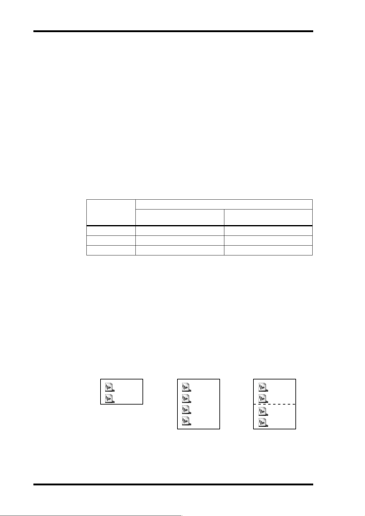
Impulse-Response Data
Impulse-response data contains the impulse-response information (i.e., acoustic characteristics) of a measured environment. Preset programs come with their own
impulse-response data. Each channel of a program is assigned impulse-response data,
as shown below, and data can be loaded for channels individually on the Data Load
pages. See “Loading Impulse-Response Data” on page 61 for more information. The
impulse-response data for the preset programs is loaded into the Internal Card at the
factory. It’s also on the supplied CD-ROM.
2-channel mode 4-channel mode 2-channel x2 mode
Left
Right
2-channel program
SREV1—Owner’s Manual
Front-left
Front-right
Rear-left
Rear-right
4-channel program
A-left
A-right
B-left
B-right
2-channel program x2

SREV1 Basics
Programs
There are two types of reverb program: 2-channel and 4-channel. Two-channel programs are for use with 2-channel mode and 2-channel x2 mode, while 4-channel programs are for use only with 4-channel mode. In 2-channel mode, 4-channel programs
do not appear in the program lists and vice versa. The preset programs on the supplied
CD-ROM are loaded into the Internal Card at the factory. User programs can be stored
in the Quick memories, Internal Card or PC Card, where they can be write-protected.
Projects
Projects contain all the Quick memory programs and the current program settings and
free you to leave a project and come back to it at any time. Projects can be saved to the
Internal Card or PC Card, where they can be write-protected.
There are three types of project: 2-channel, 4-channel, and 2-channel x2. Each project
type is available only when the corresponding mode is selected. You can’t, for example,
select a 2-channel project in 4-channel mode. Projects are managed on the Project
pages. See “Working with Projects” on page 48 for more information.
Quick Memories
7
Quick memories are special memories for storing programs. Unlike programs on the
Internal Card, PC Cards, and CD-ROMs, which take time to load, Quick memory programs can be recalled instantly. There are six Quick memories available in 2-channel or
4-channel mode; 12 in 2-channel x2 mode. Quick memories are managed on the Program pages. See “Working with Quick Memories” on page 42 for more information.
SREV1—Owner’s Manual
8
Chapter 1—Welcome
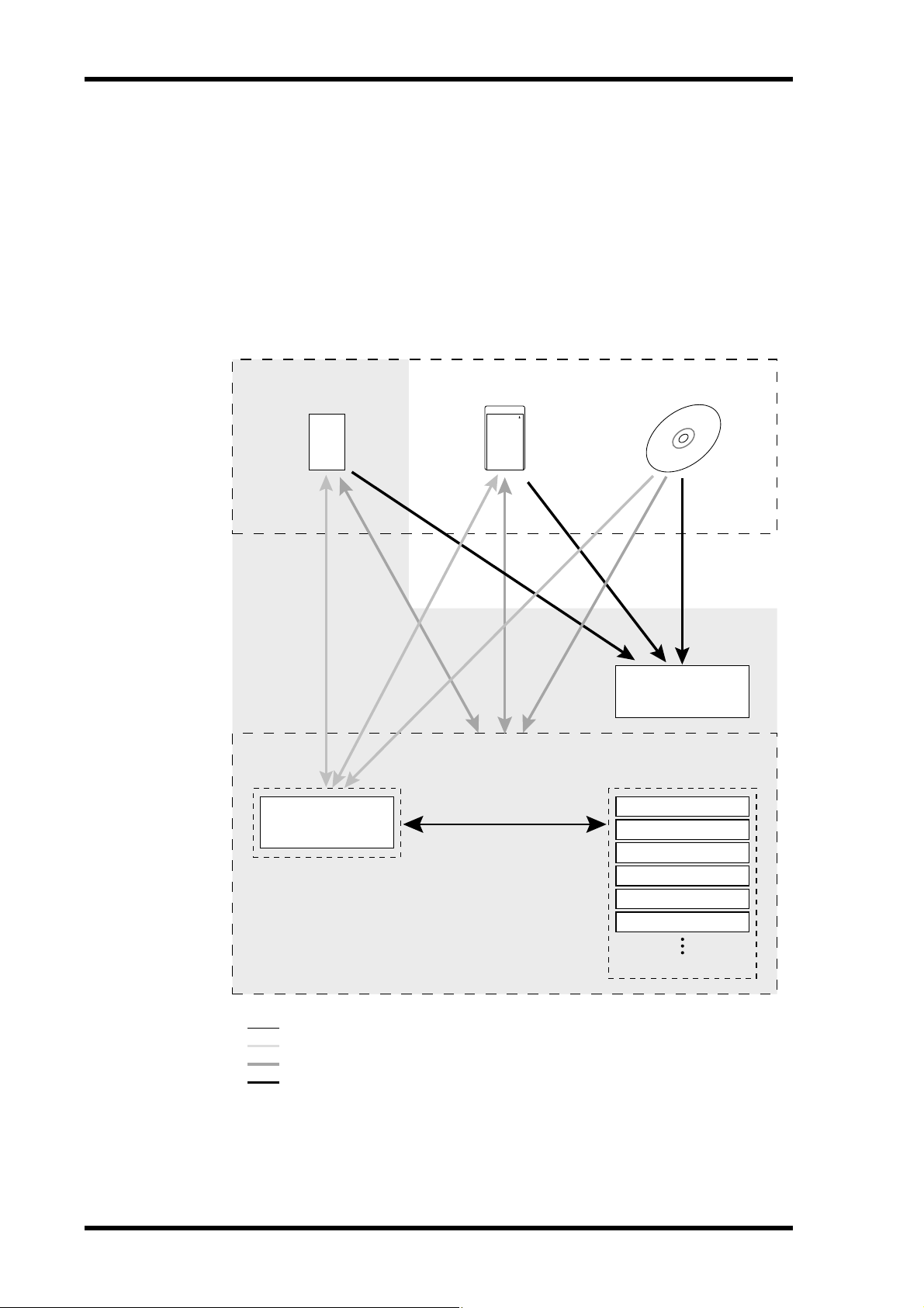
Drives
Programs, projects, and impulse-response data can be loaded from the following
drives: Internal Card, PC Card, or CD-ROM. The number of programs that can be
stored on each drive depends on its capacity and the size of the associated
impulse-response data. Programs and drives are managed on the Library pages. See
“Working with the Library” on page 45 for more information.
The following diagram shows how programs and projects can be transferred to and
from the drives and Quick memories, and impulse-response data transferred from the
drives.
Drives
PC ATA CARD
FLASH CARD
CD-ROMPC CardInternal Card
Impulse-response
Project
Current program
Quick memories
See the Program pages for Quick memory store/recall operations
See the Library pages for program and drive save/load operations
See the Project pages for project and drive save/load operations
See the Data Load pages for impulse-response data loading
data
P01
P02
P03
P04
P05
P06
SREV1—Owner’s Manual
SREV1 Basics 9
File Types
The SREV1 uses several file extensions to identify file types. Although these extensions
do not generally appear on the RC-SREV1 pages, they may come in useful when checking the contents of a PC Card or CD-ROM on your PC.
File
Extension
TM4 Impulse-response data (Yamaha original format)
TMC Compressed and encrypted impulse-response data (Yamaha original format)
SP2 2-channel program
SP4 4-channel program
2CH 2-channel mode project
4CH 4-channel mode project
2X2 2-channel x2 mode project
File Type
Parameters
SREV1 program parameters, such as reverb time, initial delay, an EQ, are stored within
each program. Saved parameters include: reverb time, initial delay, reverb balance,
reverb level, pre EQ, post EQ, and impulse-response data names.
Other parameters, including reverb mode, wordclock source, I/O select, I/O level, and
MIDI settings, are not stored within each program, but they are stored in the SREV1’s
battery-backed memory.
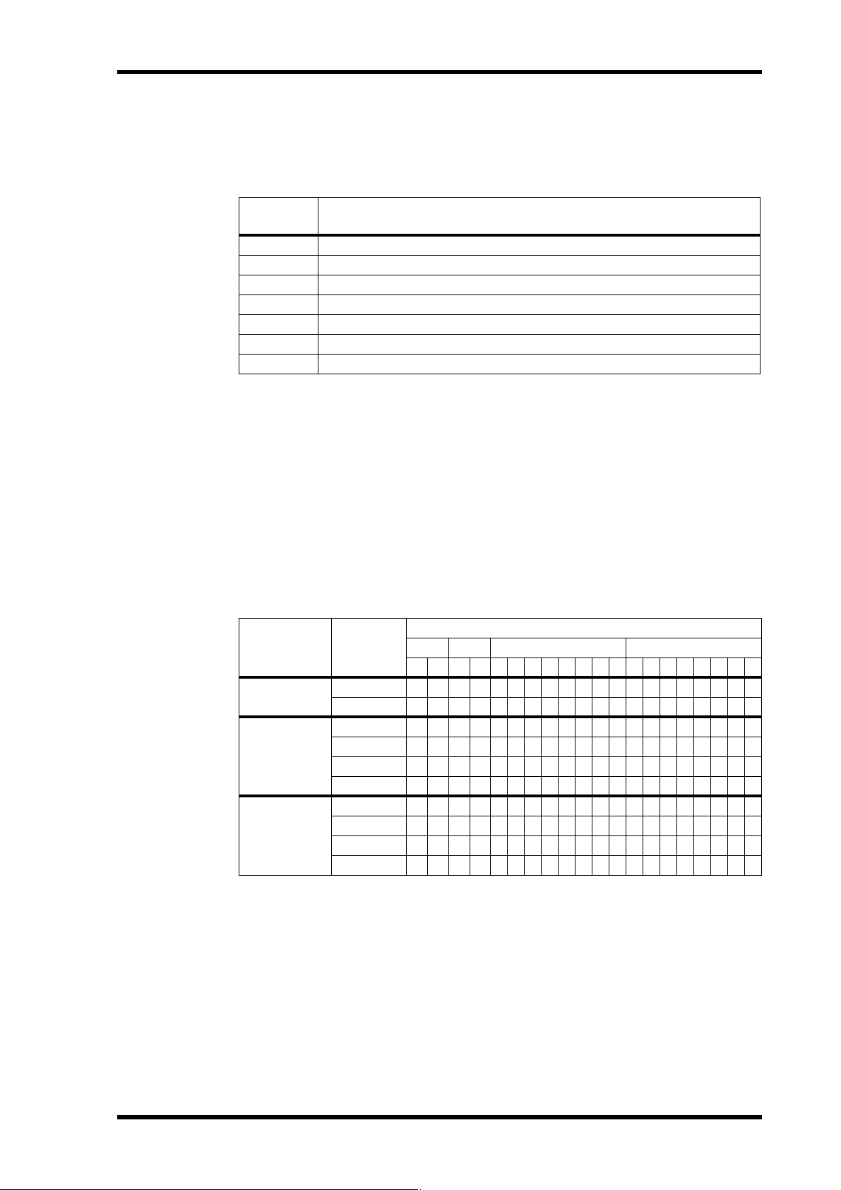
Output Assignments
The following table shows the fixed output assignments for each mode.
Mode Channel
2-channel
4-channel
2-channel x2
Left •• •
Right •• •
Front-left •• •
Front-right •• •
Rear-left •• •
Rear-right •• •
A-left •• •
A-right •• •
B-left •• •
B-right •• •
Outputs
AES1 AES2 SLOT1 SLOT2
12121234567812345678
SREV1—Owner’s Manual
SREV1—Owner’s Manual
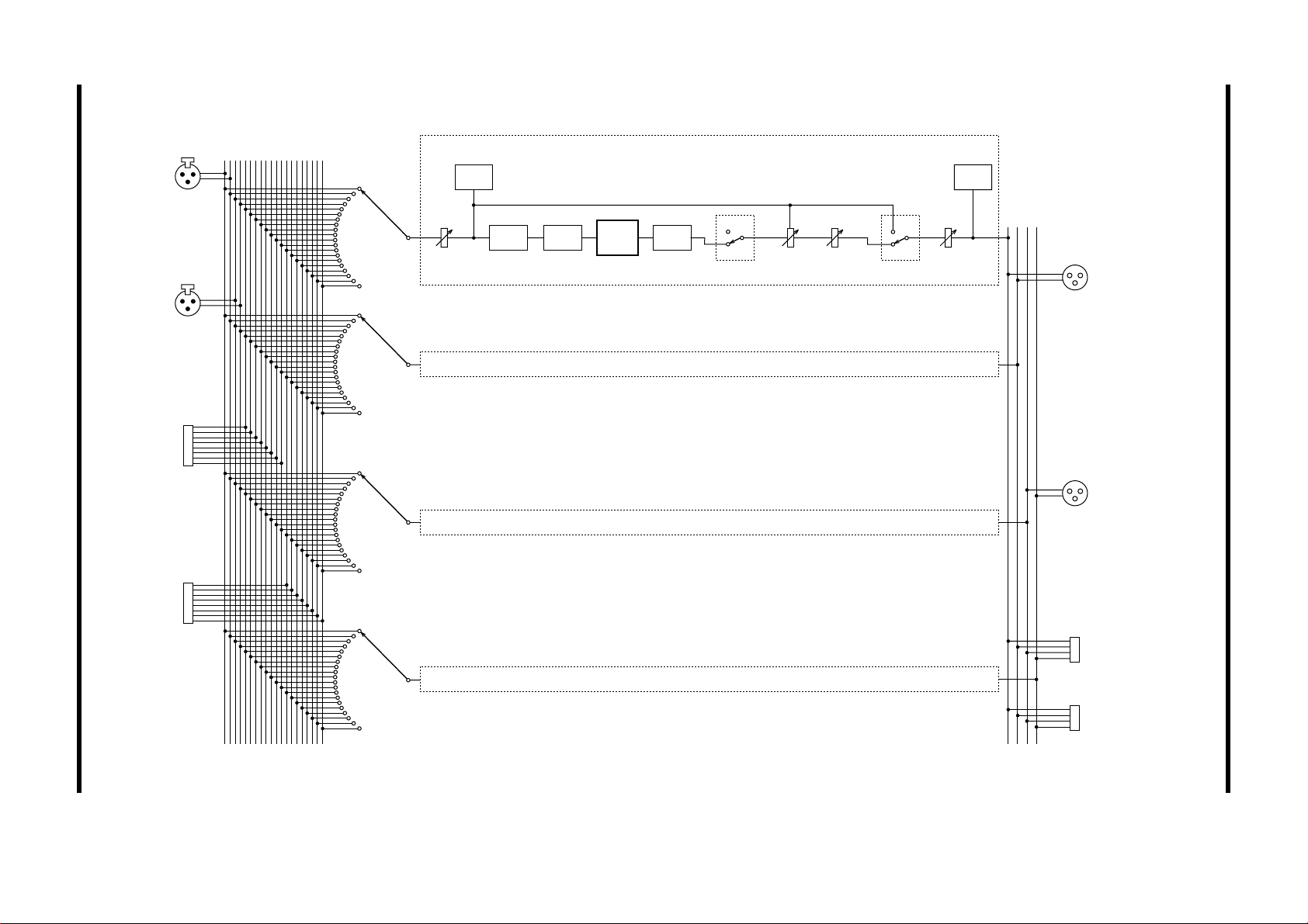
AES/EBU
IN 1
AES/EBU
IN 2
SLOT 1
Input
Select
(Left, Front-left, A-left)
Input
Meter
Input
Level
Initial
Delay
Pre EQ
Convo-
lution
As above (Right, Front-right, A-right)
As above (Rear-left, B-left)
Post EQ
On
Off
Bypass
(Rev Mute)
Reverb
Balance
Reverb
Level
On
Off
Bypass
(Direct Out)
Output
Level
Output
Meter
AES/EBU
OUT 1
AES/EBU
OUT 2
10 Chapter 1—Welcome
SREV1 Block Diagram
SLOT 2
SLOT 1
As above (Rear-right, B-right)
SLOT 2

Touring the SREV1 & RC-SREV1 11
Touring the SREV1 & RC-SREV1
2
In this chapter...
SREV1 Front Panel . . . . . . . . . . . . . . . . . . . . . . . . . . . . . . . . . . . . . . . . . . . . . . . . 12
SREV1 Rear Panel . . . . . . . . . . . . . . . . . . . . . . . . . . . . . . . . . . . . . . . . . . . . . . . . . 14
RC-SREV1 Control Surface . . . . . . . . . . . . . . . . . . . . . . . . . . . . . . . . . . . . . . . . . 16
RC-SREV1 Display . . . . . . . . . . . . . . . . . . . . . . . . . . . . . . . . . . . . . . . . . . . . . . . . 18
RC-SREV1 Rear Panel . . . . . . . . . . . . . . . . . . . . . . . . . . . . . . . . . . . . . . . . . . . . . 20
SREV1—Owner’s Manual
12 Chapter 2—Touring the SREV1 & RC-SREV1
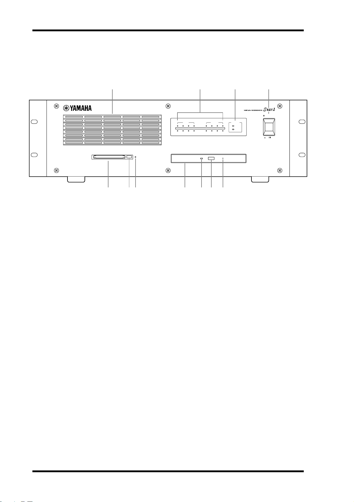
SREV1 Front Panel
1 2 3 4
INPUT OUTPUT
12 123CH434
CLIP
SIGNAL
FS LOCK
48K
44.1K
POWER
ON OFF
MEMORY CARD
CD-ROM
J9 K85 67
A Air Inlet
The two internal cooling fans draw air into the SREV1 through this inlet. If the airflow
is restricted, the SREV1 may overheat, so make sure that it’s not blocked.
B INPUT and OUTPUT signal indicators
The INPUT and OUTPUT signal level indicators consist of SIGNAL and CLIP indicators for each channel. The SIGNAL indicators light up when a signal is 34 dB below
clipping and are intended to show the presence of a signal, while the CLIP indicators
light up when a signal is actually clipping. See “Metering” on page 37 for more information.
C FS LOCK indicators
These indicators show the sampling rate—48 kHz or 44.1 kHz—and whether or not
the SREV1 is locked to the selected wordclock source. See “Selecting the Wordclock
Source” on page 75 for more information.
D POWER switch & indicator
This switch is used to turn on the power to the SREV1. The POWER indicator lights up
when the SREV1 is turned on. See “Turning On & Off the SREV1” on page 26 for more
information.
E MEMORY CARD slot
PC Cards can be inserted here for loading and saving programs, projects, or
impulse-response data. See “Using PC Cards” on page 29 for more information.
F Memory card eject button
This button is used to eject PC Cards. See “Using PC Cards” on page 29 for more information.
G Memory card activity indicator
This indicator lights up when the inserted PC Card is being written or read. See “Using
PC Cards” on page 29 for more information.
SREV1—Owner’s Manual

SREV1 Front Panel 13
H CD-ROM drive
The supplied CD-ROM, containing reverb programs, projects, and impulse-response
data, can be inserted here. See “Using CD-ROMs” on page 28 for more information.
I Disc activity indicator
This indicator lights up when the inserted CD-ROM is being read. See “Using
CD-ROMs” on page 28 for more information.
J CD-ROM eject button
This button is used to eject CD-ROMs. See “Using CD-ROMs” on page 28 for more
information.
K Emergency disc eject hole
This hole is used to manually eject CD-ROMs that cannot be ejected in the normal way.
Use a pin-like tool of 2 mm or less in diameter, insert it into the hole and push gently.
(A straightened paper clip makes an ideal tool.) Note that this technique should only be
used as a last resort. Frequent use may lead to malfunction.
SREV1—Owner’s Manual
14 Chapter 2—Touring the SREV1 & RC-SREV1
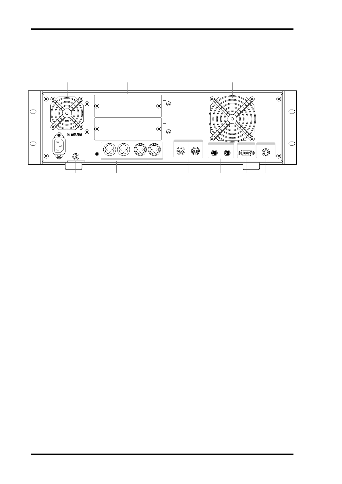
SREV1 Rear Panel
21 1
SLOT
SLOT
1
2
AC IN
3 4
A Cooling fan outlets
The two cooling fans expel air out through these outlets. If the airflow is restricted, the
SREV1 may overheat, so make sure these outlets are not blocked.
B SLOTs 1 & 2
These two slots are for use with optional mini YGDAI cards, offering a variety of analog
and digital I/O options. See “I/O Options” on page 81 for more information. Slot inputs
can be freely assigned to channels. See “Assigning Inputs” on page 35 for more information.
C AC IN connector
This connector is used to connect the SREV1 to a suitable AC outlet by using the supplied power cord. See “Connecting the Power Cord” on page 26 for more information.
D Grounding screw
For safety reasons, it’s important that the SREV1 is grounded properly. The supplied
power cord has a three-pin plug, and if the ground terminal of the AC outlet is
grounded, then the SREV1 will be grounded sufficiently through the power cord. If the
AC outlet does not provide a suitable ground, however, a ground connection should be
made to this grounding screw. Grounding is also an effective method for eliminating
hum, interference, and other noise.
3
12
5
3
12
DIGITAL (AES/EBU
1212
231
231
)
INOUT
6 J987
OUT INMIDI
2
SERIAL 1
WORD CLOCK INREMOTE
E DIGITAL OUT (AES/EBU) connectors
These two XLR-3-32-type connectors (AES1 and AES2) transmit up to four output signals, two per connection, as AES/EBU format digital audio. Output to channel assignments are fixed. See “Output Assignments” on page 9 for more information. Use only
dedicated AES/EBU connecting cables (110Ω).
F DIGITAL IN (AES/EBU) connectors
These two XLR-3-31-type connectors (AES1 and AES2) receive up to four input signals, two per connection, as AES/EBU format digital audio. AES/EBU inputs can be
freely assigned to channels. See “Assigning Inputs” on page 35 for more information.
Use only dedicated AES/EBU connecting cables (110Ω).
SREV1—Owner’s Manual

SREV1 Rear Panel 15
G MIDI IN & OUT ports
These standard MIDI IN and OUT ports and are used to connect the SREV1 to other
MIDI equipment for remote operation using MIDI Program Change and Control
Change messages. See “MIDI & the SREV1” on page 68 for more information.
H SERIAL 1 & 2 ports
These 8-pin mini DIN connectors are used to connect up to four SREV1s in a multiple-unit system. See “Multiple SREV1s” on page 63 for more information.
I REMOTE port
This 9-pin D-sub connector is used to connect the RC-SREV1. See “Connecting the
RC-SREV1 Remote Controller” on page 22 for more information.
J WORD CLOCK IN connector
This BNC connector can be used to receive an external wordclock signal. See “Wo r dclock Connections” on page 74 for more information.
SREV1—Owner’s Manual
16 Chapter 2—Touring the SREV1 & RC-SREV1
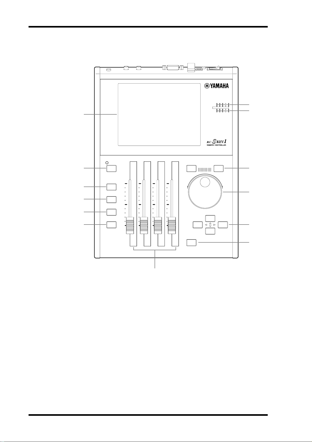
RC-SREV1 Control Surface
1
2
3
4
5
6
BYPASS
PROGRAM
PARAMETER
MAIN
PARAMETER
FINE
UTILITY
INPUT CLIP
CH
1234
OUTPUT CLIP
-1/DEC +1/INC
PARAMETER
CURSOR
ENTER
8
9
J
K
L
M
7
A Display
See “RC-SREV1 Display” on page 18 for more information.
B BYPASS button & indicator
This button is used to bypass the SREV1. The BYPASS indicator lights up when the
SREV1 is bypassed. See “Bypassing the SREV1” on page 40 for more information.
C PROGRAM button
This button selects the Program, Library, and Project pages.
D PARAMETER MAIN button
This button selects the Main 1 and Main 2 pages.
E PARAMETER FINE button
This button selects the Rev, Pre EQ, and Post EQ pages.
F UTILITY button
This button selects the Setup, DIO, Meter I/O, and MIDI pages.
SREV1—Owner’s Manual

RC-SREV1 Control Surface 17
G Motorized faders
These four 60-mm motorized faders are for adjusting parameter values and input and
output levels.
H INPUT CLIP indicators
There are four INPUT CLIP indicators, one for each channel, which light up when the
corresponding channel’s input signal is clipping.
I OUTPUT CLIP indicators
There are four OUTPUT CLIP indicators, one for each channel, which light up when
the corresponding channel’s output signal is clipping.
J –1/DEC & +1/INC buttons
These buttons work in parallel with the DATA wheel and are used for selecting programs or projects and setting parameter values. Use the [–1/DEC] button to decrease a
value; the [+1/INC] button to increase it.
K DATA wheel
This wheel is used for selecting programs or projects and setting parameter values. Turn
it clockwise to increase a value; counterclockwise to decrease it.
L Cursor buttons ( / / / )
These buttons are used to maneuver the cursor around the display pages in order to
select buttons and parameters. The left ( ) button moves the cursor to the left; the
right ( ) button moves it to the right; the up ( ) button moves it up; the down ( )
button moves it down.
M ENTER button
This button is used to execute functions and set options and parameters.
SREV1—Owner’s Manual
18 Chapter 2—Touring the SREV1 & RC-SREV1
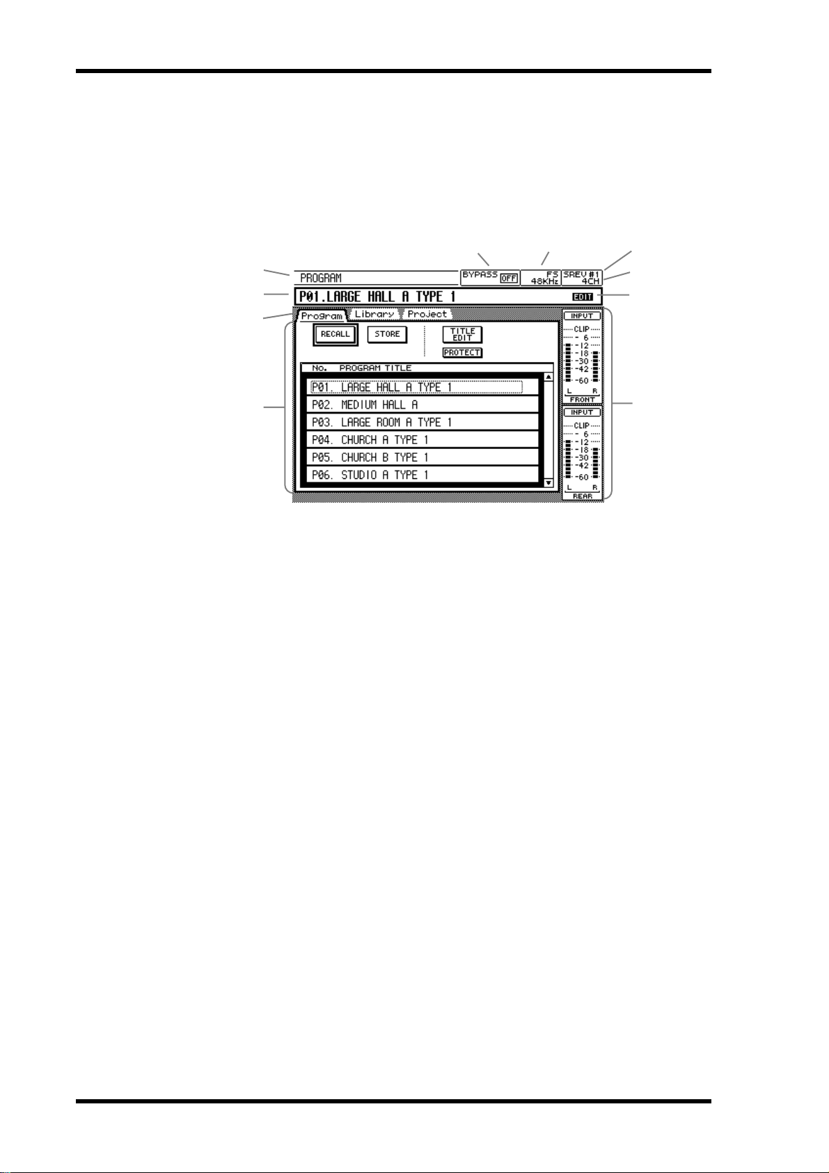
RC-SREV1 Display
This large 320 x 240 dot display, with fluorescent backlight and adjustable brightness
and contrast controls, displays the various program, parameter, and utility pages, system status, and signal level meters. As well as showing parameter values numerically,
reverb and EQ parameters are displayed graphically, so you can see settings at a glance.
Page title
Program number & title
Page tabs
Main page area
Page title—This is the title of the currently selected page.
Program number & title—This is the number and title of the current program. In
2-channel x2 mode, two numbers and titles are displayed, one for program A, the other
for program B. Program numbers appear only when programs are recalled or stored in
Quick memory. They do not appear when programs are loaded from a drive (i.e., Internal Card, PC Card, or CD-ROM).
Bypass status
FS status
Selected SREV1
Reverb mode
Edit status
Meters
Page tabs—Pages are grouped as program, parameter main, parameter fine, and util-
ity, and these tabs show the titles of the pages available in each group.
Main page area—The various program, parameter, and utility pages appear here.
Bypass status—The status of the Bypass function appears here: ON (SREV1
bypassed) or OFF. See “Bypassing the SREV1” on page 40 for more information.
FS status—The SREV1 sampling rate is displayed here—48 kHz or 44.1 kHz—and
whether or not it’s locked to the selected wordclock source—LOCK or UNLOCK. See
“Selecting the Wordclock Source” on page 75 for more information.
Selected SREV1—This is the SREV1 currently selected for control from the
RC-SREV1. See “Selecting SREV1s from the RC-SREV1” on page 65 for more information.
Reverb mode—This is the current Reverb mode: 2CH, 4CH, or 2CHX2.
Edit status—The Edit status indicator shows whether or not the current reverb pro-
gram has been edited since is was recalled. If it has, the word “EDIT” appears (the letter
“E” appears in 2-channel x2 mode).
Meters—In 2-channel mode, input and output meters for the left and right channels
are displayed here. In 4-channel mode, meters for the front-left, front-right, rear-left,
and rear-right channels are displayed. In 2-channel x2 mode, meters for the A-left,
A-right, B-left, and B-right channels are displayed. For the 4-channel and 2-channel x2
modes, you can choose to display input or output meters. See “Metering” on page 37
for more information.
SREV1—Owner’s Manual
RC-SREV1 Display 19
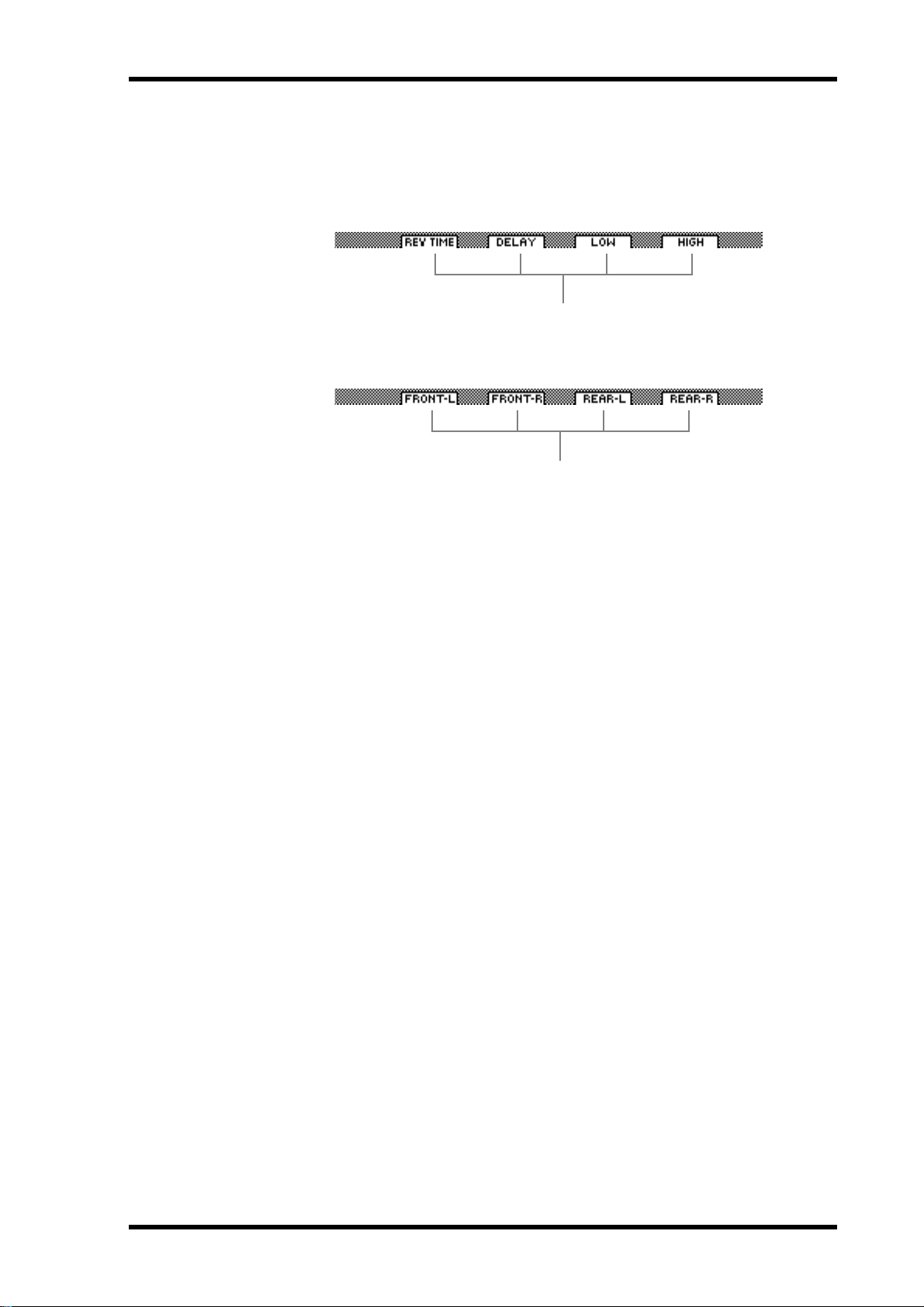
Fader status—The status of each fader appears along the bottom of the display. For
pages selected with the [PARAMETER MAIN] button, the names of the parameters
assigned to the faders appear, and for pages selected with the [PARAMETER FINE]
button, the channel names appear, as shown below.
Parameter
Channel
SREV1—Owner’s Manual
20 Chapter 2—Touring the SREV1 & RC-SREV1
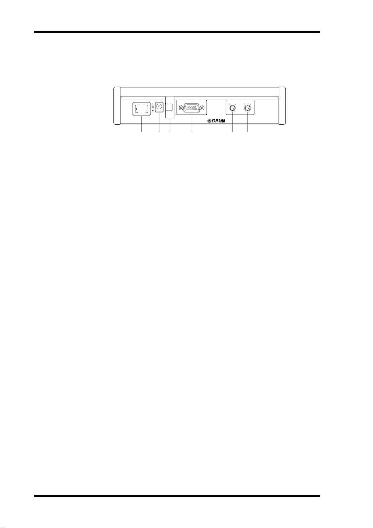
RC-SREV1 Rear Panel
REMOTEDC 12V INPOWER
ON OFF
LCD
BRIGHT CONT
1 2 3 4 5 6
A POWER switch
This switch is used to turn on the power to the RC-SREV1. Power is supplied by the
SREV1 via the remote cable, or an optional AC adapter. See “Turning On & Off the
RC-SREV1” on page 26 for more information.
B DC 12V IN connector
An optional AC adapter can be connected here (necessary when a custom-made remote
cable is used). See “Using an Optional RC-SREV1 AC Adapter” on page 27 for more
information.
C Adapter cable clip
This clip is used to secure the optional AC adapter’s cable in order to prevent accidental
disconnection. See “Using an Optional RC-SREV1 AC Adapter” on page 27 for more
information.
D REMOTE port
This 9-pin D-sub connector is used to connect the RC-SREV1 to the SREV1 with the
remote cable supplied with the RC-SREV1. See “Connecting the RC-SREV1 Remote
Controller” on page 22 for more information.
E BRIGHT control
This control is used to adjust the brightness of the display. See “Adjusting the
RC-SREV1 Brightness & Contrast” on page 27 for more information.
F CONT control
This control is used to adjust the contrast of the display. See “Adjusting the RC-SREV1
Brightness & Contrast” on page 27 for more information.
SREV1—Owner’s Manual
 Loading...