

Page 1
English
E-1
Français
Deutsch
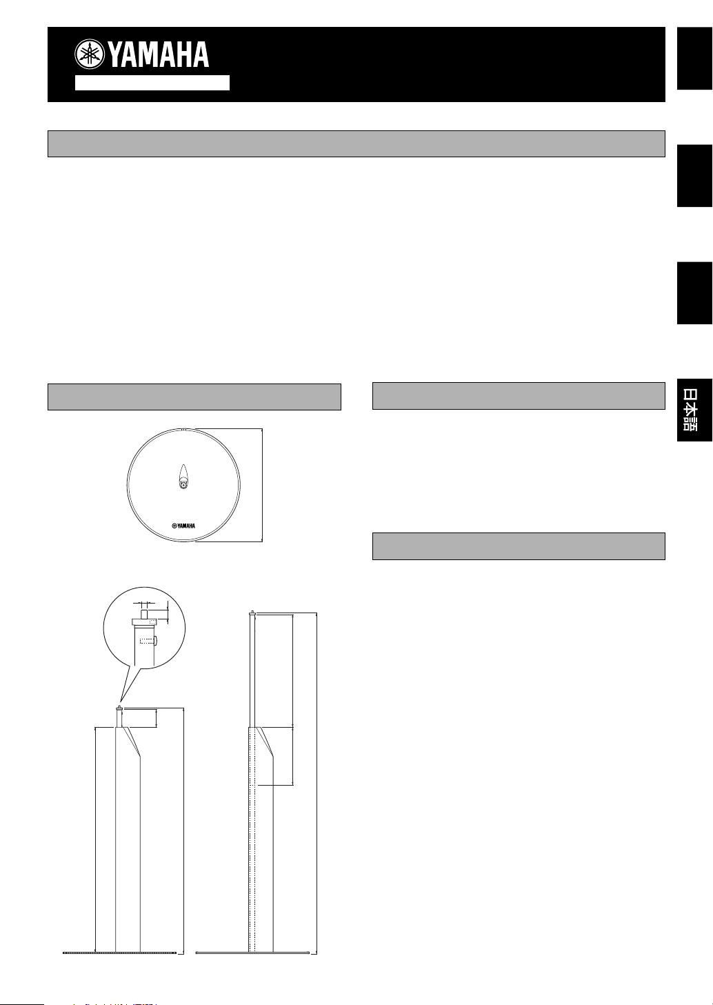
595 (23-7/16”)
297 (11-11/16”)
900 (35-7/16”)
650 (25-9/16”)
153 (6”)
47(1-7/8”)
6 (1/4”)
M4 (3/16”)
300 (11-13/16”)
● This speaker stand is only for the speaker systems listed
in “USABLE SPEAKERS” below. Do not use the
speakers other than these listed.
● To prevent the speaker from falling, use the screws and
parts provided with the stand.
● To prevent the speaker stand from falling over, select a
location which is flat and stable.
● To avoid accidents resulting from tripping over loose
speaker cables and to prevent the speaker stand from
falling over, fix the speaker cables to the wall, etc.
● Do not let the children lean on the stand as this might
cause the serious accidents resulting from the falling
over of the speaker stand.
PRECAUTIONS
Dimensions (W x H x D): 300 x 650 – 900 x 300mm
(11-13/16” x 25-9/16”
– 35-7/16” x 11-13/16”)
Weight: 2.1 kg (4 lbs. 10 oz.)
YAMAHA
● NX-230P
(the main and rear speakers included in the NS-P230/
NS-P236 speaker package)
● NX-220P
(the main and rear speakers included in the NS-P220
speaker package)
● NX-S80S
(the front and rear speakers included in the AVX-S80
sound system)
● NX-S60S
(the front and rear speakers included in the DVX-S60
sound system)
● NX-S77E
(the rear speakers included in the AV-S77 sound
system)
● NX-VS10E
(the rear speakers included in the VS-10 sound system)
* Use a speaker of 1 kg or less.
* Use a speaker with a screw hole of 4 mm in diameter
for attaching the speaker mounting bracket.
DIMENSIONS
SPS-80
SPEAKER STAND
Read this before setup
Thank you for selecting this YAMAHA SPS-80 speaker stand.
● To prevent the speaker stand from discoloring and
warping, keep the speaker stand away from the stoves
and places where it will be exposed to direct sunlight,
etc.
● Do not attempt to clean the speaker stand with chemical
solvents as this might damage the finish. Use a clean,
dry cloth.
● Secure placement or installation is the owner’s
responsibility.
YAMAHA shall not be liable for any accident caused
by improper placement or installation of speakers.
SETUP
INSTRUCTIONS
SPECIFICATIONS
USABLE SPEAKERS
Top view
Side view
(When shortened to minimum)
(When extended to maximum)
(mm/inch)
Page 2
E-2
䡵 SETUP PROCEDURES
(You will need a screwdriver for the setup.)
1
Attach the support to the base by fastening the
three + face screws from the holes on the bottom
of the base.
* Do not overtighten the + self-machine screws. Doing
so may damage the screws or assembly.
2
Pass the speaker cable through the support from
the bottom.
* A speaker cable more than 4 mm x 2 mm in diameter
cannot be used. If you use such a cable, connect it to
the speaker’s terminals without passing it through the
pole.
NAME QUANTITY
1 Pole 2
2 Support 2
3 Base 2
4 + face screws 6
(Diam. x Length: 4 x 8 mm)
5 Hexagon socket set screws 5
(Diam. x Length: 4 x 6 mm)
6 Wrench (hexagonal) 1
7 Cable protection seal 2
8 Rubber cap 2
SETUP PROCEDURES
Before beginning the setup, check the parts list
and make sure all the parts are included.
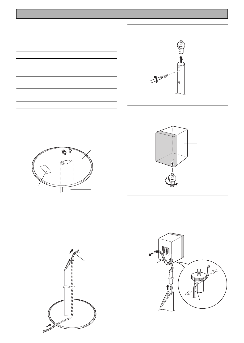
3
Remove the speaker mounting bracket from the
pole by removing the screw using the screwdriver.
4
Attach the speaker mounting bracket to the
speaker by screwing it into the screw hole on the
bottom of the speaker.
5
Pass the speaker cable through the pole from the
end without the cut.
Then pass the cable through the hole on the
speaker mounting bracket from the side with the
groove as shown in the figure.
Base
Support
Speaker cable
(not included)
Speaker
(not included)
Support
Speaker
mounting
bracket
Pole
Speaker
mounting
bracket
Pole
Speaker cable
Cut
Groove
Name plate
Front
Back
Page 3

English
E-3
6
Pull out the speaker cable in the length of 15 to 16
cm from the speaker mounting bracket. Then attach
the speaker mounting bracket to the pole so that
the speaker cable fits to the cut in the pole. This
will lock the speaker cable. After that, fasten the
screw.
7
Insert the pole to the support, and adjust the height
of the stand. After adjusting the height, fasten the
hexagon socket set screws into the two holes on
the support using the longer handle of the included
wrench, and attach the rubber cap to the support.
* The line on the pole shows the limit of the stand
height. Do not let the line of the stand height limit go
beyond the upper end of the support. Otherwise, the
hexagon socket set screw of the lower side becomes
ineffective and the fixation becomes unstable.
8
Adjust the speaker direction. Then put the wrench
into the hole of the speaker monting braket, and
tighten the bracket to the speaker by moving the
wrench counterclockwise.
9
Connect the speaker cable to the speaker’s
terminals correctly.
* Refer to the instruction manual of the speakers for
connecting the speaker cables.
10
Align the speaker cable to the grooved part of
the bottom of the base, and fix the cable on the
base by putting the protection seal on it.
The setup has completed.
In the same way, set up the other stand.
Make sure to note the following when stretching or
shortening the pole after the setup.
● Make sure to remove the cable protection seal before
stretching or shortening the pole.
● When stretching the pole, pull out the pole carefully with
the speaker stand laying along.
● When shortening the pole, retract the pole carefully
while pulling out the speaker cable slowly by hand from
the base side with the speaker stand laying along.
Wrench
(hexagonal)
15–16 cm
* Rubber cap
Hexagon
socket set
screw
Stand height
limit
Support
Cable
protection
seal
Cut
* The inside of the rubber cap has a space for
storing the wrench after the setup.
Screw
Page 4

YAMAHA ELECTRONICS CORPORATION, USA 6660 ORANGETHORPE AVE., BUENA PARK, CALIF. 90620, U.S.A.
YAMAHA CANADA MUSIC LTD. 135 MILNER AVE., SCARBOROUGH, ONTARIO M1S 3R1, CANADA
YAMAHA ELECTRONIK EUROPA G.m.b.H. SIEMENSSTR, 22-34, 25462 RELLINGEN, BEI HAMBURG, F.R. OF GERMANY
YAMAHA ELECTRONIQUE FRANCE S.A. RUE AMBROISE CROIZAT BP70 CROISSY-BEAUBOURG 77312 MARNE-LA-VALLEE CEDEX02, FRANCE
YAMAHA ELECTRONICS (UK) LTD. YAMAHA HOUSE, 200 RICKMANSWORTH ROAD WATFORD, HERTS WD1 7JS, ENGLAND
YAMAHA SCANDINAVIA A.B. J A WETTERGRENS GATA 1, BOX 30053, 400 43 VASTRA FRÖLUNDA, SWEDEN
YAMAHA MUSIC AUSTRALIA PTY, LTD. 17-33 MARKET ST., SOUTH MELBOURNE, 3205 VIC., AUSTRALIA
Printed in China V975830
Page 5

documentation manual, user maintenance, brochure, user reference, pdf manual
This file has been downloaded from:
User Manual and User Guide for many equipments like mobile phones, photo cameras, monther board, monitors, software, tv, dvd, and othes..
Manual users, user manuals, user guide manual, owners manual, instruction manual, manual owner, manual owner's, manual guide,
manual operation, operating manual, user's manual, operating instructions, manual operators, manual operator, manual product,
 Loading...