

Yamaha Audio RX-485RDS User Manual

RX-485 RDS/385 /385 RDS
Natural Sound Stereo Receiver
Ampli-syntoniseur stéréo de la série “Natural Sound”
Natural Sound Stereoreceiver
Natural Sound Stereoreceiver
Ricevitore stereo a suono naturale
Receptor estéreo de Sonido Natural
Natural Sound Stereo Ontvanger
OWNER’S MANUAL
MODE D’EMPLOI
BEDIENUNGSANLEITUNG
BRUKSANVISNING
MANUALE DI ISTRUZIONI
MANUAL DE INSTRUCCIONES
GEBRUIKSAANWIJZING
SUPPLIED ACCESSORIES
ACCESSOIRES FOURNIS
MITGELIEFERTE ZUBEHÖRTEILE
MEDFÖLJANDE TILLBEHÖR
ACCESSORI IN DOTAZIONE
ACCESORIOS INCLUIDOS
BIJGELEVERDE ACCESSOIRES
●
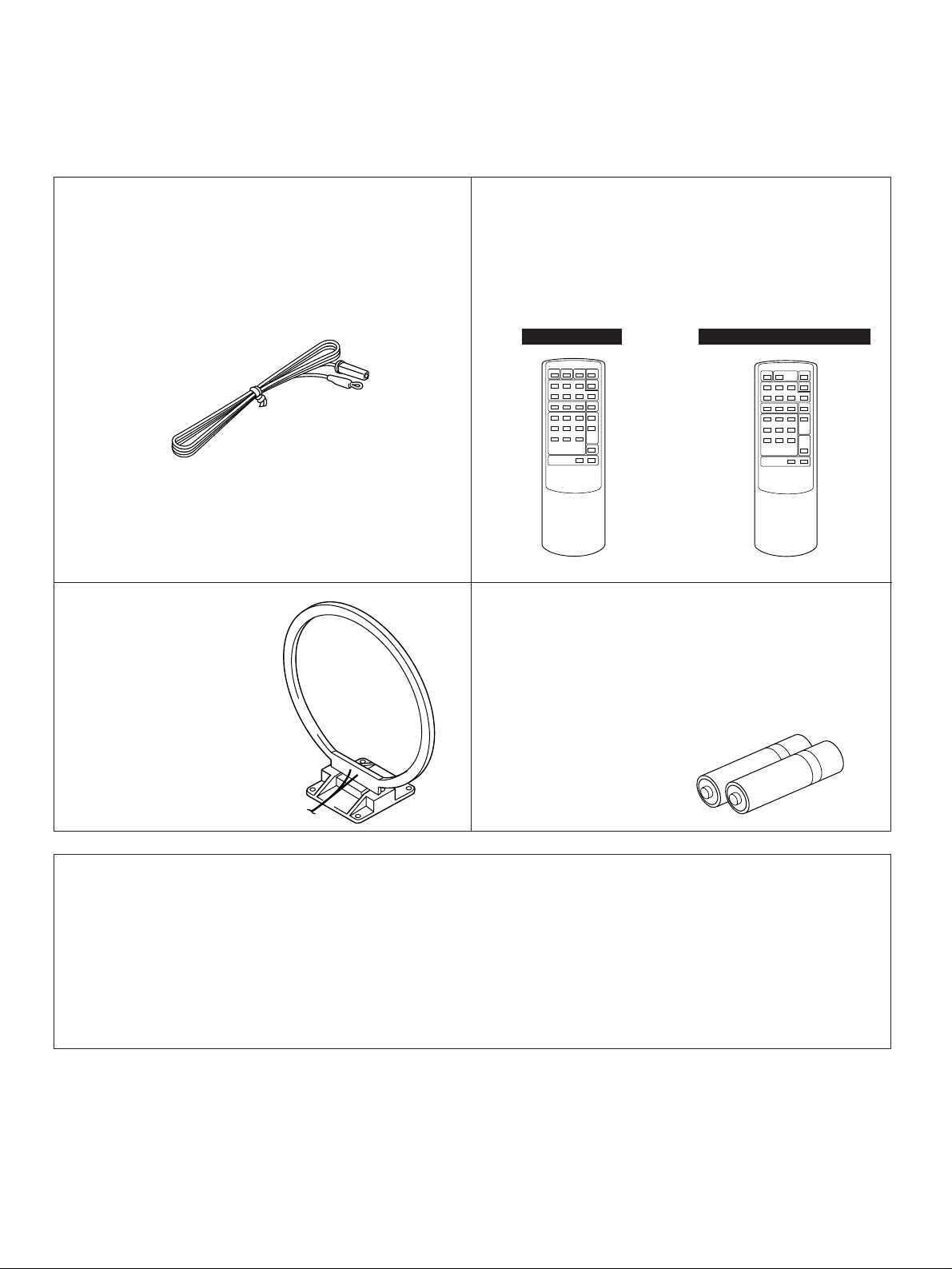
After unpacking, check that the following parts are contained.
●
Après le déballage, vérifier que les pièces suivantes sont incluses.
●
Nach dem Auspacken überprüfen, ob die folgenden Teile vorhanden sind.
●
Kontrollera effer det apparaten packats upp att följande delar finns med.
●
Verificare che tutte le parti seguenti siano contenute nell’imballaggio dell’apparecchio.
●
Desembale el aparato y verifique que los siguientes accesorios están en la caja.
●
Controleer na het uitpakken of de volgende onderdelen voorhanden zijn.
●
Indoor FM Antenna
●
Antenne FM intérieure
●
UKW-Innenantenne
●
FM inomhusantenn
●
Antenna FM per interni
●
Antena FM interior
●
FM Binnenantenne
●
AM Loop Antenna
●
Antenne AM à boucle
●
MW-Rahmenantenne
●
AM ramantenn
●
Antenna AM ad anello
●
Antena de cuadro de AM
●
AM Lusantenne
●
Remote Control Transmitter
●
Emetteur de télécommande
●
Fernbedienungsgeber
●
Fjärrkontrollsändare
●
Telecomando
●
Transmisor del control remoto
●
Afstandbediening
RX-485 RDS
●
Batteries (size AA, R6, UM-3)
●
Piles (taille AA, R6, UM-3)
●
Batterien (größ AA, R6, UM-3)
●
Batterier (storlek AA, R6, UM-3)
●
Batterie (dimensioni AA, R6, UM-3)
●
Pilas (tamaño AA, R6, UM-3)
●
Batterijen (maat AA, R6, UM-3)
RX-385, RX-385 RDS
This product complies with the radio frequency interference requirements of the Council Directive 82/499/EEC and/or
87/308/EEC.
Cet appareil est conforme aux prescriptions de la directive communautaire 87/308/CEE.
Diese Geräte entsprechen der EG-Richtlinie 82/499/EWG und/oder 87/308/EWG.
Dette apparat overholder det gaeldende EF-direktiv vedrørende radiostøj.
Questo apparecchio è conforme al D.M.13 aprile 1989 (Direttiva CEE/87/308) sulla soppressione dei radiodisturbi.
Este producto está de acuerdo con los requisitos sobre interferencias de radio frecuencia fijados por el Consejo Directivo
87/308 CEE.
Dit product voldoet aan de EEG normen betreffende radio-frekwentie storingen 82/499/EEG en/of 87/308/EEG.
2
FEATURES
Thank you for selecting this YAMAHA stereo receiver.
English
●
RX-485 RDS
65W +65W (8Ω) RMS Output Power,
0.04% THD, 20 – 20,000 Hz
RX-385 and RX-385 RDS
40W +40W (8Ω) RMS Output Power,
0.04% THD, 20 – 20,000 Hz
●
High Dynamic Power, Low Impedance
Drive Capability
●
Continuously Variable Loudness Control
●
40-Station Random Preset Tuning
●
Automatic Preset Tuning
●
Preset Station Shifting Capability
CONTENTS
●
IF Count Direct PLL Synthesizer Tuning
System
●
Remote Control Capability
RX-485 RDS and RX-385 RDS only
●
Multi-Functions for RDS Broadcast
Reception
RX-485 RDS only
●
Pure Direct Switch to Reproduce the
Purest Source Sound
Supplied Accessories ......................................2
Caution ............................................................4
Remote Control Transmitter ..........................21
Notes about the Remote Control
Transmitter ....................................................22
Connections ....................................................5
Troubleshooting .............................................23
Operations .......................................................9
Specifications ................................................24
Tuning Operations .........................................12
Preset tuning .................................................13
Receiving RDS Stations
RX-485 RDS and RX-385 RDS only ..........16
How to Use This Manual
This manual describes three YAMAHA receivers, RX-385, RX-385 RDS and RX-485 RDS. There are some differences between
those three models. Especially, RX-385 RDS and RX-485 RDS contain the functions for receiving special data on RDS network
stations.
RX-385, on the other hand, is a receiver with a usual FM/AM tuning function.
Several places in the manual refer to differences in features between the three models. Be sure to follow the procedure for the
model you are using.
* RDS is a data transmitting service system in network which is employed by FM stations. RDS stations are increasing in many
countries (especially in Europe).
3
CAUTION: READ THIS BEFORE OPERATING YOUR UNIT.
1. To assure the finest performance, please read this manual
carefully. Keep it in a safe place for future reference.
2. Install this unit in a cool, dry, clean place – away from windows,
heat sources, sources of excessive vibration, dust, moisture and
cold. Avoid sources of humming (transformers, motors). To
prevent fire or electrical shock, do not expose the unit to rain or
water.
3. Never open the cabinet. If something drops into the set, contact
your dealer.
4. Do not use force on switches, controls or connection wires. When
moving the unit, first disconnect the power plug and the wires
connected to other equipment. Never pull the wires themselves.
5. The openings on the cabinet assure proper ventilation of the unit.
If these openings are obstructed, the temperature inside the
cabinet will rise rapidly and eventually damage the circuits.
Therefore, avoid placing objects against these openings and do
not install the unit where the flow of air through the ventilation
openings could be impeded.
6. Always set the VOLUME control to “–
source play. Increase the volume gradually to an appropriate level
after playback has been started.
” before starting the audio
∞
7. Do not attempt to clean the unit with chemical solvents; this might
damage the finish. Use a clean, dry cloth.
8. Be sure to read the “TROUBLESHOOTING” section regarding
common operating errors before concluding that the unit is faulty.
9. When not planning to use this unit for long periods of time (ie.,
vacation, etc.), disconnect the AC power plug from the wall outlet.
10.To prevent lightning damage, disconnect the AC power plug and
disconnect the antenna cable when there is an electrical storm.
IMPORTANT
Please record the serial number of this unit in the space below.
Serial No.:
The serial number is located on the rear of the unit.
Retain this Owner’s Manual in a safe place for future reference.
WARNING
TO REDUCE THE RISK OF FIRE OR ELECTRIC SHOCK, DO
NOT EXPOSE THIS UNIT TO RAIN OR MOISTURE.
CAUTION (FOR CANADA MODEL)
TO PREVENT ELECTRIC SHOCK, MATCH WIDE BLADE OF
PLUG TO WIDE SLOT AND FULLY INSERT.
FOR CANADIAN CUSTOMER
THIS DIGITAL APPARATUS DOES NOT EXCEED THE “CLASS B”
LIMITS FOR RADIO NOISE EMISSIONS FROM DIGITAL
APPARATUS SET OUT IN THE RADIO INTERFERENCE
REGULATION OF THE CANADIAN DEPARTMENT OF
COMMUNICATIONS.
The apparatus is not disconnected from the AC power
source as long as it is connected to the wall outlet, even if
the apparatus itself is turned off.
For U.K. customers
If the socket outlets in the home are not suitable for the plug
supplied with this appliance, it should be cut off and an
appropriate 3 pin plug fitted. For details, refer to the
instructions described below.
Note: The plug severed from the mains lead must be
destroyed, as a plug with bared flexible cord is hazardous if
engaged in a live socket outlet.
SPECIAL INSTRUCTIONS FOR U.K. MODEL
11.Grounding or polarization – Precautions should be taken so that
the grounding or polarization of an appliance is not defeated.
12.AC outlet
Do not connect audio equipment to the AC outlet on the rear panel
if that equipment requires more power than the outlet is rated to
provide.
13.Voltage Selector (General Model only)
The voltage selector on the rear panel of this unit must be set
for your local main voltage BEFORE plugging into the AC
main supply.
Voltages are 110/120/220/240V AC, 50/60 Hz.
IMPORTANT:
The wire in the mains lead are coloured in accordance with
the following code:
Blue: NEUTRAL
Brown: LIVE
The colours of the wires in the mains lead of this apparatus
may not correspond with the coloured markings identifying
the terminals in your plug. Proceed as follows: the wire
which is coloured BLUE must be connected to the terminal
which is marked with the letter N or coloured BLACK. The
wire which is coloured BROWN must be connected to the
terminal which is marked with the letter L or coloured RED.
Making sure that neither core is connected to the earth
terminal of the three pin plug.
FREQUENCY STEP switch (General Model only)
Because the interstation frequency spacing differs in different
areas, set the FREQUENCY STEP switch (located at the rear)
according to the frequency spacing in your area.
Before setting this switch, disconnect the AC power plug of this unit
from the AC outlet.
4
CONNECTIONS
75Ω
UNBAL
PHONO CD AUX
FM
ANT
GND
AM
ANT
TAPE
PB
300-ohm
feeder
75-ohm
coaxial cable
75-ohm/300-ohm
antenna adapter
Ground
Outdoor FM antenna
Indoor FM
antenna
(included)
Outdoor AM antenna
AM loop
antenna
(included)
➀
➁
➂
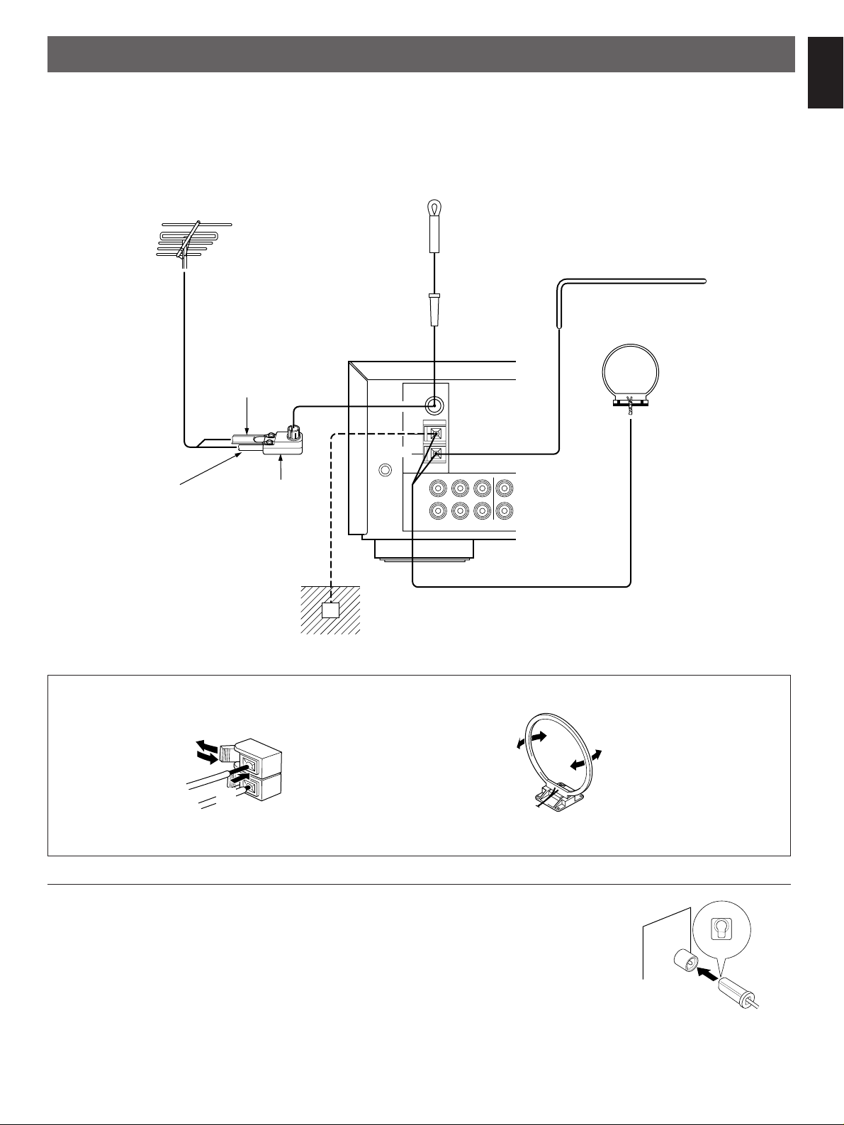
ANTENNA CONNECTIONS
●
Each antenna should be connected to the designated terminals correctly, referring to the following figure.
●
Both AM and FM indoor antennas are included with this unit. In general, these antennas will probably provide sufficient signal
strength. Nevertheless, a properly installed outdoor antenna will give clearer reception than an indoor one. If you experience
poor reception quality, an outdoor antenna may result in improvement.
English
Connecting the AM loop antenna
* The AM loop antenna should be placed apart from the main unit. The antenna may be hung on a wall.
* The AM loop antenna should be kept connected, even if an outdoor AM antenna is connected to this unit.
GND terminal
For maximum safety and minimum interference, connect the
GND terminal to a good earth ground. A good earth ground is
a metal stake driven into moist earth.
Notes
●
When connecting the indoor
FM antenna, make sure that
the grooved part of the
connector hole is facing
downward.
●
If you need an outdoor
FM antenna to improve
FM reception quality, either 300-ohm feeder or coaxial cable
may be used. In locations troubled by electrical
interference, coaxial cable is preferable.
Orient so that the best
reception is obtained.
5
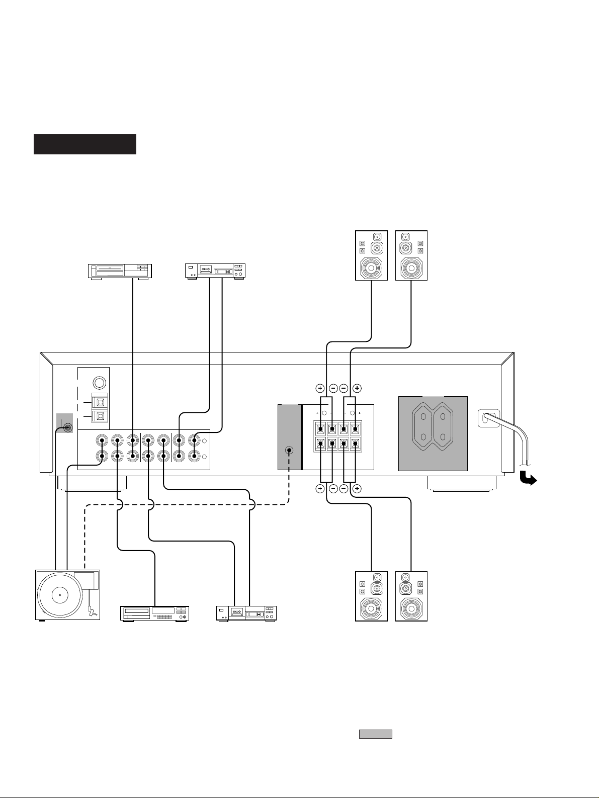
Before attempting to make any connections to or from this unit, be sure to first switch OFF the power to this unit and to any other
R L
A
B
75Ω
UNBAL
PHONO CD AUX
A
B
FM
ANT
GND
AM
ANT
TAPEPBREC
OUT
TAPE 1
SPEAKERS
Video cassette player etc.
Turntable Compact disc player Tape deck 1
To AC outlet
Speakers A
Right Left
Right Left
Speakers B
TAPEPBREC
OUT
TAPE 2
Tape deck 2
R
L
OUTPUT
GND
REMOTE CONTROL
AUDIO OUT
LINE OUT
LINE IN
OUTPUT
LINE IN
LINE OUT
100W MAX. TOTAL
SWITCHED
AC OUTLETS
REMOTE
CONTR0L
PHONO
GND
components to which connections are being made.
AUDIO CONNECTIONS
When making connections between this unit and other components, be sure all connections are made correctly, that is to say L
(left) to L, R (right) to R, “+” to “+” and “–” to “–”. Also, refer to the owner’s manual for each component to be connected to this unit.
RX-485 RDS
(Europe model)
6
* : Refer to “ABOUT THE ACCESSORY
TERMINALS” on page 8.
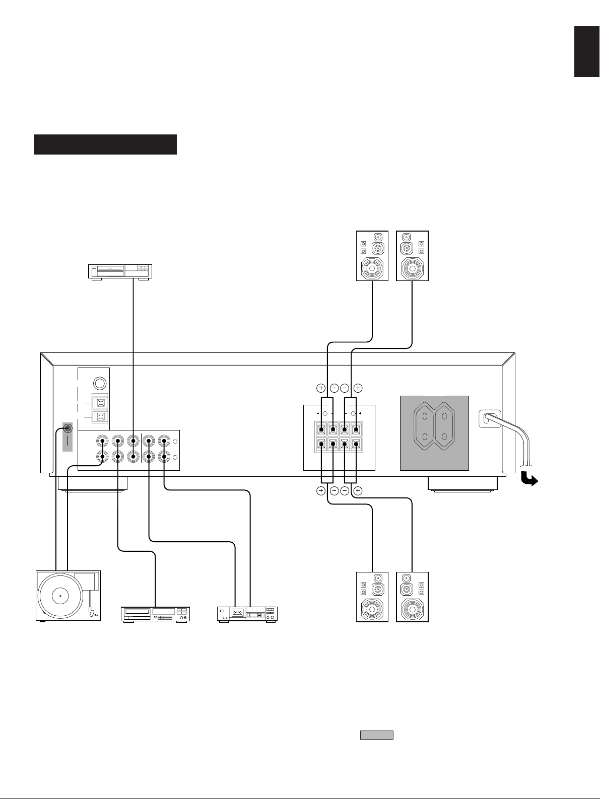
RX-385, RX-385 RDS
R L
A
B
75Ω
UNBAL
PHONO CD AUX
A
B
FM
ANT
GND
AM
ANT
TAPEPBREC
OUT
TAPE 1
SPEAKERS
Video cassette player etc.
Turntable Compact disc player Tape deck
To AC outlet
Speakers A
Right Left
Right Left
Speakers B
R
L
OUTPUT
GND
AUDIO OUT
OUTPUT
LINE IN
LINE OUT
100W MAX. TOTAL
SWITCHED
AC OUTLETS
GND
English
(Europe model)
* : Refer to “ABOUT THE ACCESSORY
TERMINALS” on page 8.
7
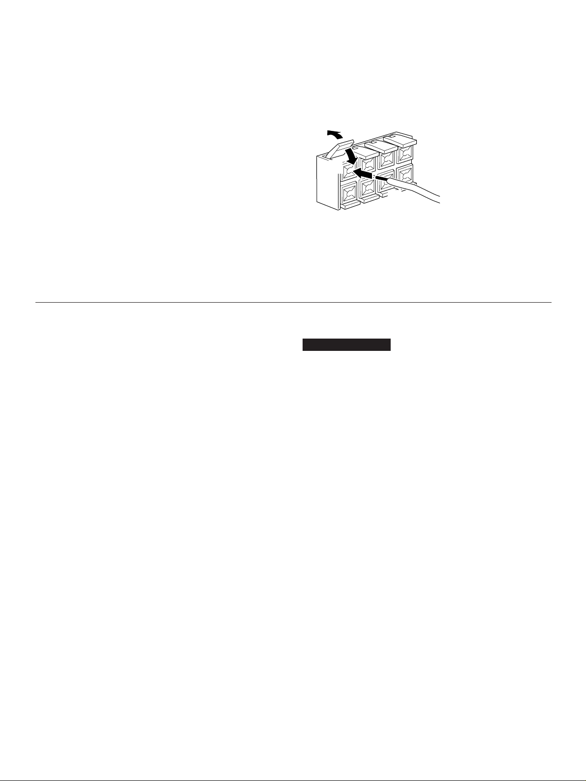
CONNECTING SPEAKERS
➀
➁
➂
Connect the SPEAKERS terminals to your speakers with wire
of the proper gauge, cut to be as short as possible. If the
connections are faulty, no sound will be heard from the
speakers. Make sure that the polarity of the speaker wires is
correct, that is, + and – markings are observed. If these wires
are reversed, the sound will be unnatural and will lack bass.
Do not let the bare speaker wires touch each other and do
not let them touch the metal parts of this unit as this could
damage this unit and/or speakers.
●
One or two speaker systems can be connected to this unit.
If you connect only one speaker system, connect it to either
the SPEAKERS A or B terminals.
●
Use speakers with the specified impedance shown on the
rear of this unit.
ABOUT THE ACCESSORY TERMINALS
AC OUTLET(S)
(Europe model) ...................................2 SWITCHED OUTLETS
(U.K. model) ..........................................1 SWITCHED OUTLET
Use these to connect the power cords from your components
to this unit.
The power to the SWITCHED outlets is controlled by this unit’s
POWER switch or the provided remote control transmitter’s
POWER key. These outlets will supply power to any
component whenever this unit is turned on.
The maximum power (total power consumption of
components) that can be connected to the SWITCHED AC
OUTLET(S) is 100 watts.
How to Connect:
Red: positive (+)
Black: negative (–)
Press up the tab.
➀
Insert the bare wire.
➁
[Remove approx. 5mm
(1/4”) insulation from
the speaker wires.]
Press down the tab and
➂
secure the wire.
REMOTE CONTROL (PHONO) connector
RX-485 RDS only
If you have a YAMAHA turntable with a terminal for remote
control, connect it to this connector by using the cable provided
with the turntable. This connection allows you to control the
turntable from the provided remote control transmitter.
GND terminal (For turntable use)
Connecting the ground wire of the turntable to this terminal will
normally minimize hum, but in some cases better results may
be obtained with the ground wire disconnected.
8
 Loading...