

Page 1
RS75
ASSEMBLY INSTRUCTIONS
INTRODUCTION
Thank you for purchasing the Yamaha Electronic Drum Rack System RS75.
Before using, thoroughly read these assembly instructions, and use this product
safely and correctly.
PRECAUTIONS
Before using, please read this “Assembly Instruction” sheet, and use this product in a safe
and proper manner.
Especially for children, parents or an instructor
should teach the children the proper manner in
which to use the device.
WARNING
Always set the instrument on a flat and solid surface. Placement on a sloping, unstable surface or on steps may result in the
instrument being unstable and overturning.
Make sure all bolts are tightened firmly. Loose bolts may result in the rack overturning or parts dropping causing injury.
When adjusting the height or angle, do not suddenly loosen the bolt. The pad may drop, the rack or pipes may slip, pinching or
causing injury to hands or fingers.
Do not sit or step on the rack. The rack may overturn or be damaged resulting in injury.
Please be careful when children are close to or touching the product. The product has many pipes and arms so careless
movement around the product may result in injury.
When setting the pads and modules, please pay close attention in regards to the handling and setting of cables. Feet may
become entangled in the cables resulting in falls.
CAUTION
If this symbol is ignored and the equipment is used improperly, fatal injury to per-
sons or serious damage could occur.
If this symbol is ignored and the equipment is used improperly, there is a danger
of injury to persons handling the equipment, and material damage could occur.
To prevent against accidents and injury
Please follow the cautions listed below
Caution (including danger, or warning). This
mark indicates cautions in which you should
pay close attention to.
Acts indicated with this icon are prohibited and
should not be attempted.
■ Handling Precautions
• Do not alter the product. Doing so may result in damage or deterioration to the product.
• Do not step on or place heavy objects on the product. It may result in damage.
• Do not use or keep the product in places with extremely high temperature (places in direct sunlight, close to a heater, in a closed car, etc.) or damp (bathroom, outside on a rainy day, etc.). It
may result in deformation, discoloration, stickiness, damage or deterioration.
•To clean the product, please wipe with a soft cloth or a damp cloth that has been wrung out
thoroughly. If the product is soiled or sticky, use a neutral detergent on a cloth then wipe with a
damp cloth that has been wrung out thoroughly to remove any remaining detergent.
benzine, thinner or alcohol as it may result in discoloration or deformation. Also pay close attention so as not to let the water and detergent come into contact with the cushions used in the
product, it may result in deterioration.
Do not use
■ Inside This Package
Before setup, please make sure that all of the items listed below are present and accounted for. If anything is missing, please contact the dealer from whom you purchased
the unit.
◆ Overall Assembly RS75
(When the box is opened)
◆ Small Screws M5 X 8
(Module Holder Fixing Screws X4)
◆ Cable Band (x10)
Do not put your hands or feet under the foot pedal or foot switch. They may be pinched resulting in injury.
Watch your fingers when adjusting clamps. They may become pinched resulting in injury.
Be careful around pipe ends, inside the pipe and screw ends. Metal shavings, etc. may injure your fingers.
Do not attach acoustic drums to the electronic drum rack. Clamps may be damaged and drums may drop, causing injury.
* Specifications are subject to change without notice.
◆ Rubber Foot (x2)
◆ Assembly Instructions (this sheet)
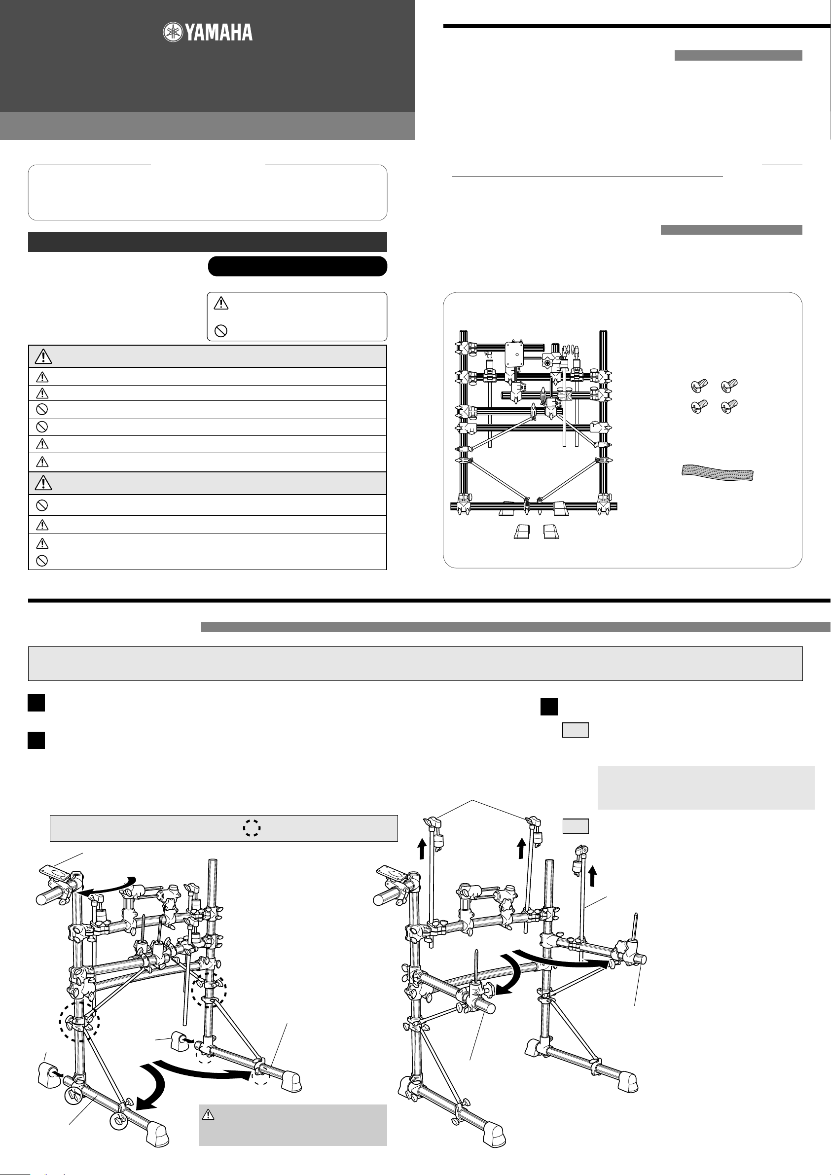
■ RS75 Assembly
* Parts for the RS75's main structure have already been assembled before packing. After removing the unit from the box, follow the instructions described below to complete the assembly.
A Phillips (+) screwdriver is required when attaching the Drum Trigger Module. Please prepare one before starting assembly.
After removing the unit from the box, remove all cushion material.
1
Setting up the parts
2
• Loosen the wing bolts, slide the pipes out a little, and attach the rubber feet.
• Loosen the bolts on the movable arms and legs, as shown in the diagrams
below, then secure the bolts firmly once setting is complete.
Follow the setup order (q~i) in the diagrams shown below.
Cymbal Holder
Attaching the Drum Trigger Module
3
3-1 Remove the module holder from the holder clamp,
and use the supplied screws to attach the Drum
Trigger Module.
Make sure only the supplied screws are
used. Using any other screws may result
in the unit falling off the holder or damage.
Caution : Make sure the bolts marked with a " " are loosened before setting up.
Rubber Foot
Loosen
Left Leg Assembly
Module Holder Assembly
e
Caution
←
Rubber Foot
q
Loosen
Loosen
Caution
←
Right Leg Assembly
w
Loosen
Be careful around the pipe edges.
The cut pipe ends are sharp and can
injure your fingers.
r
3-2 Reattach the module holder to the holder clamp.
t
y
Cymbal Holder
u
i
Side Arm (R) Assembly
Side Arm (L) Assembly
Page 2
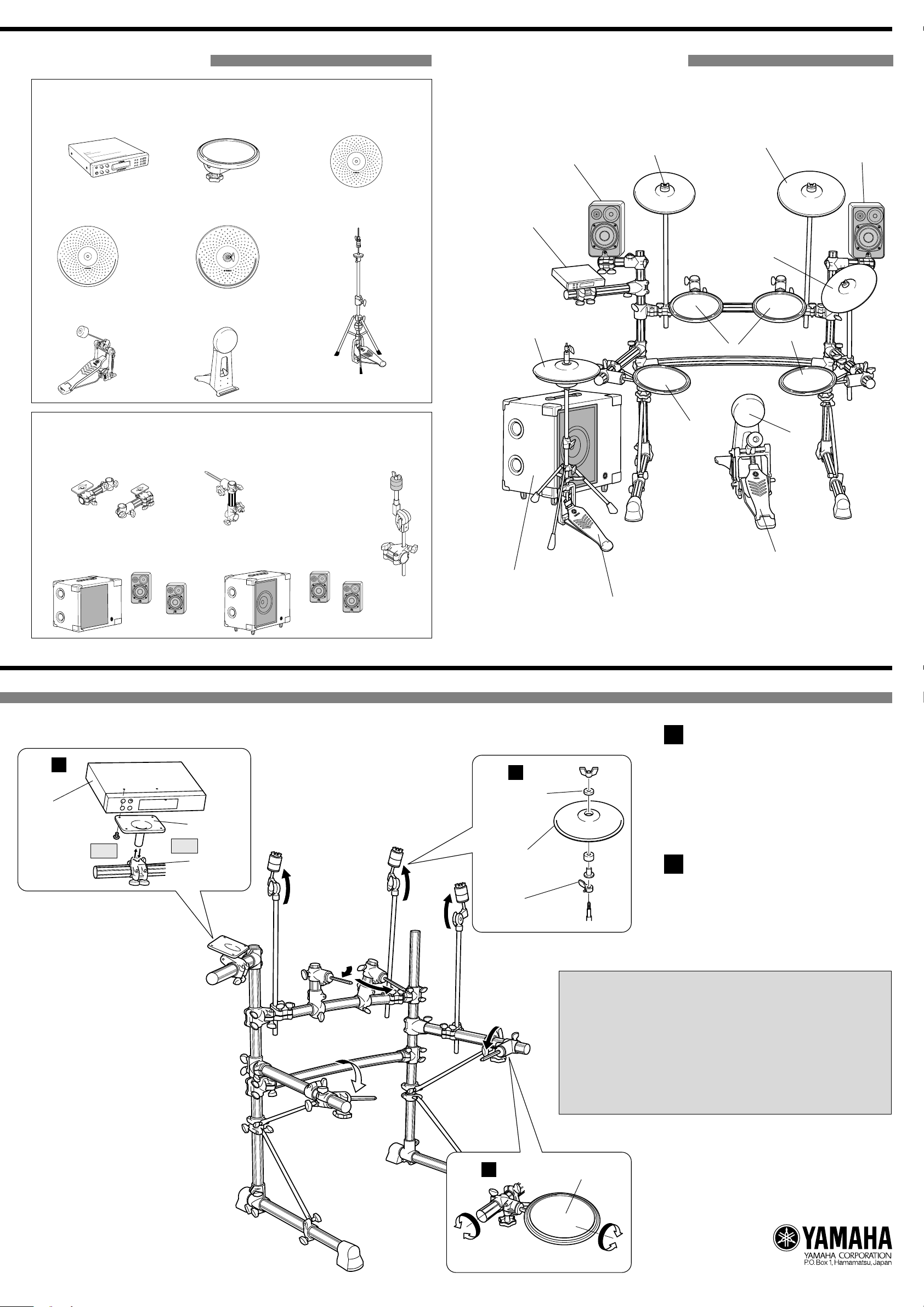
■ Optional Parts
● Pad and Drum Trigger Grouping
q DTX Series
Drum Trigger Module
w TP65/65S
Drum Pad
e PCY130/130S
Cymbal Pad
■ Set up example
PCY130S
Satellite Speaker
e
PCY150S
r
Satellite Speaker
r PCY150S
Cymbal Pad
u Foot Pedal
FP-7210 etc.
t RHH130
Real Hi-hat Pad
i KP65
Kick Pad
● Monitor System and Attachment Grouping
• SPAT1
Speaker Attachment
• TPCL65
Tom Holder
y Hi-hat stand
*HS740 etc.
• CYAT65
Cymbal Attachment
q
RHH130
t
w
TP65S
PCY130
e
w
w
i
• MS50DR
• Sub Woofer
amp unit
Step 3
Drum Trigger
Module
Step 3-1
• Satellite
Speakers
Step 3-2
• MS100DR
• Sub Woofer
amp unit
Module Holder
Holder Clamp
• Satellite
Speakers
Sub Woofer amp unit
Step 4
Felt
Cymbal Pad
(PCY130/130S/150S)
y
u
Attaching the cymbal pads
4
Attach the cymbal pads to the cymbal holders and adjust their position, then secure in
place.
(Please refer to the Owner's Manual that
came with the cymbal pads on attaching the
cymbal pads.)
Attaching the drum pads
5
Anti-swivel brace
(supplied with the
(PCY130/130S/150S)
Step 5
Attach drum pads to the hexagonal rod cylinder and adjust their position, the secure
in place.
Make sure all bolts on clamps, pads, etc., are firmly tightened.
Loose or over-tightened bolts may result in the part falling off and/or
damage. Please use caution.
After assembly is complete, setup the kick pad, real hi-hat pad, etc.,
and connect the cables. Use the supplied cable bands to secure the
cables to the frame pipes to keep cables out of the way during per-
formance.
If the rack is moved even after setup is complete, make sure the
bolts are loosened before moving the rack.
Drum Pad
Printed in Indonesia
WG24080
Page 3

documentation manual, user maintenance, brochure, user reference, pdf manual
This file has been downloaded from:
User Manual and User Guide for many equipments like mobile phones, photo cameras, monther board, monitors, software, tv, dvd, and othes..
Manual users, user manuals, user guide manual, owners manual, instruction manual, manual owner, manual owner's, manual guide,
manual operation, operating manual, user's manual, operating instructions, manual operators, manual operator, manual product,
 Loading...