

Yamaha Audio Programmable Mixer 01 User Manual

Manuel de référence
Bedienungsanleitung
1 2 3 4 5 6 7 8 9
PAD
20dB
20dB
20dB
20dB
20dB
20dB
20dB
20dB
20dB
–16 –60
–16 –60
–16 –60
–16 –60
–16 –60
–16 –60
–16 –60
–16 –60
GAIN
1
SCENE MEMORY
INC +
STORE
DEC –
RECALL
METER
PAN/ø
SEND 1
EQ-LOW
1
SEL
ON
GAIN
GAIN
GAIN
GAIN
2
3
UTILITY
MIDI
GROUP
PAIR
COMP
CUE
2
3
4
MID
HIGH
LIBRARY
2
3
SEL
SEL
ON
ON
GAIN
4
5
6
FUNCTION
MEMORY
SEL CH
4
5
6
SEL
SEL
SEL
ON
ON
ON
–16 –60
GAIN
GAIN
GAIN
7
8
9
7
8
9
SEL
SEL
SEL
ON
ON
ON
User’s Guide
Manual de uso
10 LRLR
11 12 13 14 15 16
20dB
20dB
20dB
20dB
20dB
20dB
20dB
–16 –60
–16 –60
–16 –60
–16 –60
–16 –60
–16 –60
GAIN
GAIN
GAIN
10
10
SEL
ON
GAIN
11
12
13
RTN 1
RTN 2
SEND 3
SEND 4
11
12
13
SEL
SEL
SEL
ON
ON
ON
–16 –60
GAIN
GAIN
GAIN
14
15
16
ENTER
CLIP
15
12
9
6
3
0
–6
–12
–18
–24
–40
R
L
14
15
16
SEL
SEL
SEL
ON
ON
ON
ST IN
ST IN
SEL
ON
010
LEVEL
MONITOR
OUT
PARAMETER
RTN/
SEND ST OUT
SEL
ON
2TR IN
CUE/ 2TR IN
010
LEVEL
PHONES
SEL
ON
6
6
6
6
6
6
6
6
6
6
6
6
6
6
6
6
6
6
0
0
0
0
0
0
0
0
0
0
0
0
0
0
0
5
5
5
5
5
5
5
5
5
5
5
5
10
10
10
10
10
10
10
10
10
20
20
20
20
20
20
40
40
40
60
00
1
40
60
60
60
00
00
00
2
3
4
20
40
40
40
60
60
60
00
00
00
5
6
7
10
20
20
20
40
40
40
60
60
60
00
00
00
8
9
10
5
10
10
10
20
20
20
40
40
40
60
60
60
00
00
00
11
12
13
0
5
5
5
10
10
10
20
20
20
40
40
40
60
60
60
00
00
00
14
15
16
6
0
0
0
5
5
5
10
10
10
20
20
20
40
40
40
60
60
60
00
00
00
RTN/
ST IN
ST OUT
SEND

FCC INFORMATION (U.S.A.)
1. IMPORTANT NOTICE: DO NOT MODIFY THIS UNIT!
This product, when installed as indicated in the instructions contained in this manual, meets FCC requirements. Modifications not expressly approved by
Yamaha may void your authority, granted by the FCC, to use the product.
2. IMPORTANT: When connecting this product to accessories and/or another product use only high quality shielded cables. Cable/s supplied with this product
MUST be used. Follow all installation instructions. Failure to follow instructions could void your FCC authorization to use this product in the USA.
3. NOTE: This product has been tested and found to comply with the requirements listed in FCC Regulations, Part 15 for Class “B” digital devices. Compliance
with these requirements provides a reasonable level of assurance that your use of this product in a residential environment will not result in harmful interference
with other electronic devices. This equipment generates/uses radio frequencies and, if not installed and used according to the instructions found in the users
manual, may cause interference harmful to the operation of other electronic devices. Compliance with FCC regulations does not guarantee that interference
will not occur in all installations. If this product is found to be the source of interference, which can be determined by turning the unit “OFF” and “ON”, please
try to eliminate the problem by using one of the following measures:
Relocate either this product or the device that is being affected by the interference
Utilize power outlets that are on different branch (circuit breaker of fuse) circuits or install AC line filter/s.
In the case of radio or TV interference, relocate/reorient the antenna. If the antenna lead-in is 300 ohm ribbon lead, change the lead-in to coaxial type cable.
If these corrective measures do not produce satisfactory results, please contact the local retailer authorized to distribute this type of product. If you can not locate
the appropriate retailer, please contact Yamaha Corporation of America. Electronic Service Division, 6600 Orangethorpe Ave, Buena Park, CA 90620
This applies only to products distributed by YAMAHA CORPORATION OF AMERICA
*
Dette apparat overholder det gaeldende EF-direktiv vedtrørende
radiostøj.
Cet appareil est conforme aux prescriptions de la directive
communautaire 87/308/CEE.
Diese Geräte entsprechen der EG-Richtlinie 82/499/EWG und/
oder 87/308/EWG.
This product complies with the radio frequency interference requirements of the Council Directive 82/499/EEC and/or 87/308/
EEC.
Questo apparecchio è conforme al D.M.13 aprile 1989 (Direttiva
CEE/87/308) sulla soppressione dei radiodisturbi.
Este producto está de acuerdo con los requisitos sobre interferencias
de radio frequencia fijados por el Consejo Directivo 87/308/CEE.
YAMAHA CORPORATION
IMPORTANT NOTICE FOR
THE UNITED KINGDOM
Connecting the Plug and Cord
WARNING: THIS APPARATUS MUST BE EARTHED
IMPORTANT: The wires in this mains lead are coloured in accordance with
the following code:
GREEN-AND-YELLOW : EARTH
BLUE : NEUTRAL
BROWN :LIVE
As the colours of the wires in the mains lead of this apparatus may not
correspond with the coloured markings idenlifying the terminals in your
plug, proceed as follows:
The wire which is coloured GREEN and YELLOW must be connected to the
terminal in the plug which is marked by the letter E or by the safety earth
symbol or coloured GREEN and YELLOW.
The wire which is coloured BLUE must be connected to the terminal which
is marked with the letter N or coloured BLACK.
The wire which is coloured BROWN must be connected to the terminal
which is marked with the letter L or coloured RED.
This applies only to products distributed by YAMAHA KEMBLE MUSIC (U.K.)
*
LTD.
CANADA
THIS DIGITAL APPARATUS DOES NOT EXCEED THE “CLASS
B” LIMITS FOR RADIO NOISE EMISSIONS
FROM DIGITAL APPARATUS SET OUT IN THE RADIO INTERFERENCE REGULATION OF THE CANADIAN DEPARTMENT
OF COMMUNICATIONS.
LE PRESENT APPAREIL NUMERIQUE N’EMET PAS DE BRUITS
RADIOELECTRIQUES DEPASSANT LES LIMITES APPLICABLES
AUX APPAREILS NUMERIQUES DE LA “CLASSE B”
PRESCRITES DANS LE REGLEMENT SUR LE BROUILLAGE
RADIOELECTRIQUE EDICTE PAR LE MINISTERE DES COMMUNICATIONS DU CANADA.
This applies only to products distributed by YAMAHA CANADA
*
MUSIC LTD.
Litiumbatter!
Bör endast bytas av servicepersonal.
Explosionsfara vid felaktig hantering.
VAROITUS!
Lithiumparisto, Räjähdysvaara.
Pariston saa vaihtaa ainoastaan aian
ammattimies.
ADVARSELl!
Lithiumbatter!
Eksplosionsfare. Udskiftning må kun foretages
af en sagkyndig, –og som beskrevet i
servicemanualen.
CONNEXIONS DES MICROPHONES ET DE LEURS CÂBLES
POUR ÉVITER TOUT ENDOMMAGEMENT, S’ASSURER DE
BRANCHER UNIQUEMENT DES MICROPHONES ET DES
CÂBLES DE MICROPHONES CONCUS SELON LA NORME
IEC268-15A.
MICROPHONE CABLES AND MICROPHONES CONNECTION
TO PREVENT HAZARD OR DAMAGE, ENSURE THAT ONLY
MICROPHONE CABLES AND MICROPHONES DESIGNED TO
THE IEC268-15A STANDARD ARE CONNECTED.

i
Brief Contents
1 Touring ProMix 01 . . . . . . . . . . . . . . . 1
2 User Interface . . . . . . . . . . . . . . . . . . 11
3 Mixer Functions . . . . . . . . . . . . . . . . 17
4 Auxiliaries and Effects . . . . . . . . . . . . 29
5 CUE . . . . . . . . . . . . . . . . . . . . . . . . . . 49
6 Groups and Pairs . . . . . . . . . . . . . . . 55
7 Scene Memories . . . . . . . . . . . . . . . . 61
8 Dynamics Processors . . . . . . . . . . . . 67
9 MIDI . . . . . . . . . . . . . . . . . . . . . . . . . 79
10 Other Functions . . . . . . . . . . . . . . . . 89
Troubleshooting . . . . . . . . . . . . . . . . . . . 93
Appendix . . . . . . . . . . . . . . . . . . . . . . . . 95
Glossary . . . . . . . . . . . . . . . . . . . . . . . . 109
Index . . . . . . . . . . . . . . . . . . . . . . . . . . . 113
Additions . . . . . . . . . . . . . . . . . . . . . Add-1
Downloaded from:
MIDI Data Format . . . . . . . . . . . . . Add-16
ProMix 01 User’s Guide

ii
ProMix 01 User’s Guide

iii
Full Contents
1 Touring ProMix 01 . . . . . . . . . . . . . . . 1
Top Panel . . . . . . . . . . . . . . . . . . . . . . . . . . . . . . . . . . . . . . . . 2
Rear Panel . . . . . . . . . . . . . . . . . . . . . . . . . . . . . . . . . . . . . . . 5
ProMix 01 Block Diagram . . . . . . . . . . . . . . . . . . . . . . . . . . 8
An Analog Mixer Analogy . . . . . . . . . . . . . . . . . . . . . . . . . . 9
2 User Interface . . . . . . . . . . . . . . . . . . 11
About the User Interface . . . . . . . . . . . . . . . . . . . . . . . . . 12
LCD Display . . . . . . . . . . . . . . . . . . . . . . . . . . . . . . . . . . . 12
Cursor Buttons . . . . . . . . . . . . . . . . . . . . . . . . . . . . . . . . . 13
PARAMETER Wheel . . . . . . . . . . . . . . . . . . . . . . . . . . . . 13
ENTER Button . . . . . . . . . . . . . . . . . . . . . . . . . . . . . . . . . 13
SEL Buttons . . . . . . . . . . . . . . . . . . . . . . . . . . . . . . . . . . . . 14
LCD Functions . . . . . . . . . . . . . . . . . . . . . . . . . . . . . . . . . 15
3 Mixer Functions . . . . . . . . . . . . . . . . 17
Phantom Power . . . . . . . . . . . . . . . . . . . . . . . . . . . . . . . . . 18
Pad . . . . . . . . . . . . . . . . . . . . . . . . . . . . . . . . . . . . . . . . . . . 18
Gain . . . . . . . . . . . . . . . . . . . . . . . . . . . . . . . . . . . . . . . . . . 18
Metering . . . . . . . . . . . . . . . . . . . . . . . . . . . . . . . . . . . . . . . 19
Phase . . . . . . . . . . . . . . . . . . . . . . . . . . . . . . . . . . . . . . . . . 20
EQ . . . . . . . . . . . . . . . . . . . . . . . . . . . . . . . . . . . . . . . . . . . . 21
EQ Library . . . . . . . . . . . . . . . . . . . . . . . . . . . . . . . . . . . . . 22
EQ Presets . . . . . . . . . . . . . . . . . . . . . . . . . . . . . . . . . . . . . 23
Faders . . . . . . . . . . . . . . . . . . . . . . . . . . . . . . . . . . . . . . . . . 25
ON Buttons . . . . . . . . . . . . . . . . . . . . . . . . . . . . . . . . . . . . 25
Pan and Balance . . . . . . . . . . . . . . . . . . . . . . . . . . . . . . . . 26
Stereo Output Balance . . . . . . . . . . . . . . . . . . . . . . . . . . . 26
Stereo-Pair Pans . . . . . . . . . . . . . . . . . . . . . . . . . . . . . . . . 27
Stereo Width . . . . . . . . . . . . . . . . . . . . . . . . . . . . . . . . . . . 27
4 Auxiliaries and Effects . . . . . . . . . . . . 29
About Auxiliaries . . . . . . . . . . . . . . . . . . . . . . . . . . . . . . . 30
About Effects . . . . . . . . . . . . . . . . . . . . . . . . . . . . . . . . . . . 30
Preset Effects Programs . . . . . . . . . . . . . . . . . . . . . . . . . . 30
Stereo Input Channel and Sends . . . . . . . . . . . . . . . . . . . 31
Applying Effects . . . . . . . . . . . . . . . . . . . . . . . . . . . . . . . . 31
Sending a Channel Signal . . . . . . . . . . . . . . . . . . . . . . . . . 32
SEND1 and SEND2 Pre or Post . . . . . . . . . . . . . . . . . . . . 32
Returning the Processed Signal . . . . . . . . . . . . . . . . . . . . 33
Recalling Effects Programs . . . . . . . . . . . . . . . . . . . . . . . . 34
Editing Effects Programs . . . . . . . . . . . . . . . . . . . . . . . . . 35
Downloaded from:
ProMix 01 User’s Guide

iv
Storing Effects Programs . . . . . . . . . . . . . . . . . . . . . . . . . . 36
Preset Effects Program Parameters . . . . . . . . . . . . . . . . . . 37
SEND3 and SEND4 . . . . . . . . . . . . . . . . . . . . . . . . . . . . . . 45
SEND3 and SEND4 Pre or Post . . . . . . . . . . . . . . . . . . . . 45
SEND3-4 Stereo Pair . . . . . . . . . . . . . . . . . . . . . . . . . . . . . 46
SEND3-4 Channel Pans & Balance . . . . . . . . . . . . . . . . . . 47
SEND3-4 Output Balance . . . . . . . . . . . . . . . . . . . . . . . . . 47
SEND3-4 Block Diagram . . . . . . . . . . . . . . . . . . . . . . . . . . 48
5 CUE . . . . . . . . . . . . . . . . . . . . . . . . . . 49
About CUE . . . . . . . . . . . . . . . . . . . . . . . . . . . . . . . . . . . . . 50
CUE Modes . . . . . . . . . . . . . . . . . . . . . . . . . . . . . . . . . . . . . 50
Group CUE . . . . . . . . . . . . . . . . . . . . . . . . . . . . . . . . . . . . . 50
Setting the CUE Mode . . . . . . . . . . . . . . . . . . . . . . . . . . . . 51
CUE Signal Sources . . . . . . . . . . . . . . . . . . . . . . . . . . . . . . 51
CUE/2TR IN Switch . . . . . . . . . . . . . . . . . . . . . . . . . . . . . . 51
CUE LCD Function Info . . . . . . . . . . . . . . . . . . . . . . . . . . 52
6 Groups and Pairs . . . . . . . . . . . . . . . 55
Grouping Faders . . . . . . . . . . . . . . . . . . . . . . . . . . . . . . . . . 56
Listening to Groups . . . . . . . . . . . . . . . . . . . . . . . . . . . . . . 56
Group Block Diagram . . . . . . . . . . . . . . . . . . . . . . . . . . . . 57
Pairing Channels . . . . . . . . . . . . . . . . . . . . . . . . . . . . . . . . 58
Pair Block Diagram . . . . . . . . . . . . . . . . . . . . . . . . . . . . . . 59
7 Scene Memories . . . . . . . . . . . . . . . . 61
What are Scene Memories? . . . . . . . . . . . . . . . . . . . . . . . . 62
What’s Stored in a Scene Memory? . . . . . . . . . . . . . . . . . 62
What is the Edit Buffer? . . . . . . . . . . . . . . . . . . . . . . . . . . . 62
Mix Scene 00 . . . . . . . . . . . . . . . . . . . . . . . . . . . . . . . . . . . . 62
Storing Mix Scenes . . . . . . . . . . . . . . . . . . . . . . . . . . . . . . . 63
Recalling Mix Scenes . . . . . . . . . . . . . . . . . . . . . . . . . . . . . 64
Protecting Scene Memories . . . . . . . . . . . . . . . . . . . . . . . . 65
8 Dynamics Processors . . . . . . . . . . . . 67
ProMix 01 Dynamics Processors . . . . . . . . . . . . . . . . . . . . 68
Preset Dynamics Programs . . . . . . . . . . . . . . . . . . . . . . . . 68
Processor Types . . . . . . . . . . . . . . . . . . . . . . . . . . . . . . . . . 68
Patching in a Processor . . . . . . . . . . . . . . . . . . . . . . . . . . . 72
Dynamics Processor Meters . . . . . . . . . . . . . . . . . . . . . . . 73
Pre-Fader or Post-Fader Patches . . . . . . . . . . . . . . . . . . . . 74
Recalling a Dynamics Program . . . . . . . . . . . . . . . . . . . . . 75
Editing a Dynamics Program . . . . . . . . . . . . . . . . . . . . . . 76
Storing a Dynamics Program . . . . . . . . . . . . . . . . . . . . . . 77
Preset Dynamics Processor Parameters . . . . . . . . . . . . . . 78
ProMix 01 User’s Guide
Downloaded from:

v
9 MIDI . . . . . . . . . . . . . . . . . . . . . . . . . 79
MIDI and ProMix 01 . . . . . . . . . . . . . . . . . . . . . . . . . . . . 80
MIDI Setup . . . . . . . . . . . . . . . . . . . . . . . . . . . . . . . . . . . . 81
Program Change . . . . . . . . . . . . . . . . . . . . . . . . . . . . . . . . 82
Control Change . . . . . . . . . . . . . . . . . . . . . . . . . . . . . . . . . 83
Bulk Dump/Request . . . . . . . . . . . . . . . . . . . . . . . . . . . . . 85
Local ON/OFF . . . . . . . . . . . . . . . . . . . . . . . . . . . . . . . . . . 86
Memory Control Change Out . . . . . . . . . . . . . . . . . . . . . 87
10 Other Functions . . . . . . . . . . . . . . . . 89
Using the Oscillator . . . . . . . . . . . . . . . . . . . . . . . . . . . . . 90
Checking the Battery . . . . . . . . . . . . . . . . . . . . . . . . . . . . . 91
ProMix 01 Initialization . . . . . . . . . . . . . . . . . . . . . . . . . . 92
Fader Calibration . . . . . . . . . . . . . . . . . . . . . . . . . . . . . . . 92
Troubleshooting . . . . . . . . . . . . . . . . . . . 93
Appendix . . . . . . . . . . . . . . . . . . . . . . . . 95
LCD Function Map . . . . . . . . . . . . . . . . . . . . . . . . . . . . . . 96
Button Protector . . . . . . . . . . . . . . . . . . . . . . . . . . . . . . . . 97
Data Types . . . . . . . . . . . . . . . . . . . . . . . . . . . . . . . . . . . . . 98
Error Messages . . . . . . . . . . . . . . . . . . . . . . . . . . . . . . . . 100
ProMix 01 Compatible Products . . . . . . . . . . . . . . . . . . 104
General Specifications . . . . . . . . . . . . . . . . . . . . . . . . . . 105
Input Specifications . . . . . . . . . . . . . . . . . . . . . . . . . . . . 106
Output Specifications . . . . . . . . . . . . . . . . . . . . . . . . . . . 106
Digital OUT & MIDI Specifications . . . . . . . . . . . . . . . 107
Digital Out Channel Status . . . . . . . . . . . . . . . . . . . . . . 107
Glossary . . . . . . . . . . . . . . . . . . . . . . . . 109
Index . . . . . . . . . . . . . . . . . . . . . . . . . . . 113
Additions . . . . . . . . . . . . . . . . . . . . . Add-1
ProMix 01 Level Diagram . . . . . . . . . . . . . . . . . . . . . Add-1
ProMix 01 Dimensions . . . . . . . . . . . . . . . . . . . . . . . . Add-2
Optional Rack-Mount Ears . . . . . . . . . . . . . . . . . . . . Add-3
Optional Wooden Side Panels . . . . . . . . . . . . . . . . . . Add-3
Mix Scene to Program Change Assignment Table . . Add-4
Control Change to Parameter Assignment Table . . Add-5
Downloaded from:
ProMix 01 User’s Guide

vi
MIDI Data Format . . . . . . . . . . . . . Add-16
1 General Items . . . . . . . . . . . . . . . . . . . . . . . . . . . . . Add-16
2 Transmission/Reception . . . . . . . . . . . . . . . . . . . . Add-16
3 Transmission Condition . . . . . . . . . . . . . . . . . . . . Add-18
4 Receive Condition . . . . . . . . . . . . . . . . . . . . . . . . . Add-18
5 Bulk Dump Request Format . . . . . . . . . . . . . . . . Add-19
Button Number Table . . . . . . . . . . . . . . . . . . . . . . . Add-28
ProMix 01 User’s Guide
Downloaded from:

1
Touring ProMix 01
Touring ProMix 01
In this chapter...
Top Panel . . . . . . . . . . . . . . . . . . . . . . . . . . . . . . . . . . . . 2
1
Rear Panel . . . . . . . . . . . . . . . . . . . . . . . . . . . . . . . . . . . . 5
ProMix 01 Block Diagram . . . . . . . . . . . . . . . . . . . . . . 8
An Analog Mixer Analogy . . . . . . . . . . . . . . . . . . . . . . . 9
Downloaded from:
ProMix 01 User’s Guide
Chapter 1: Touring ProMix 01
2
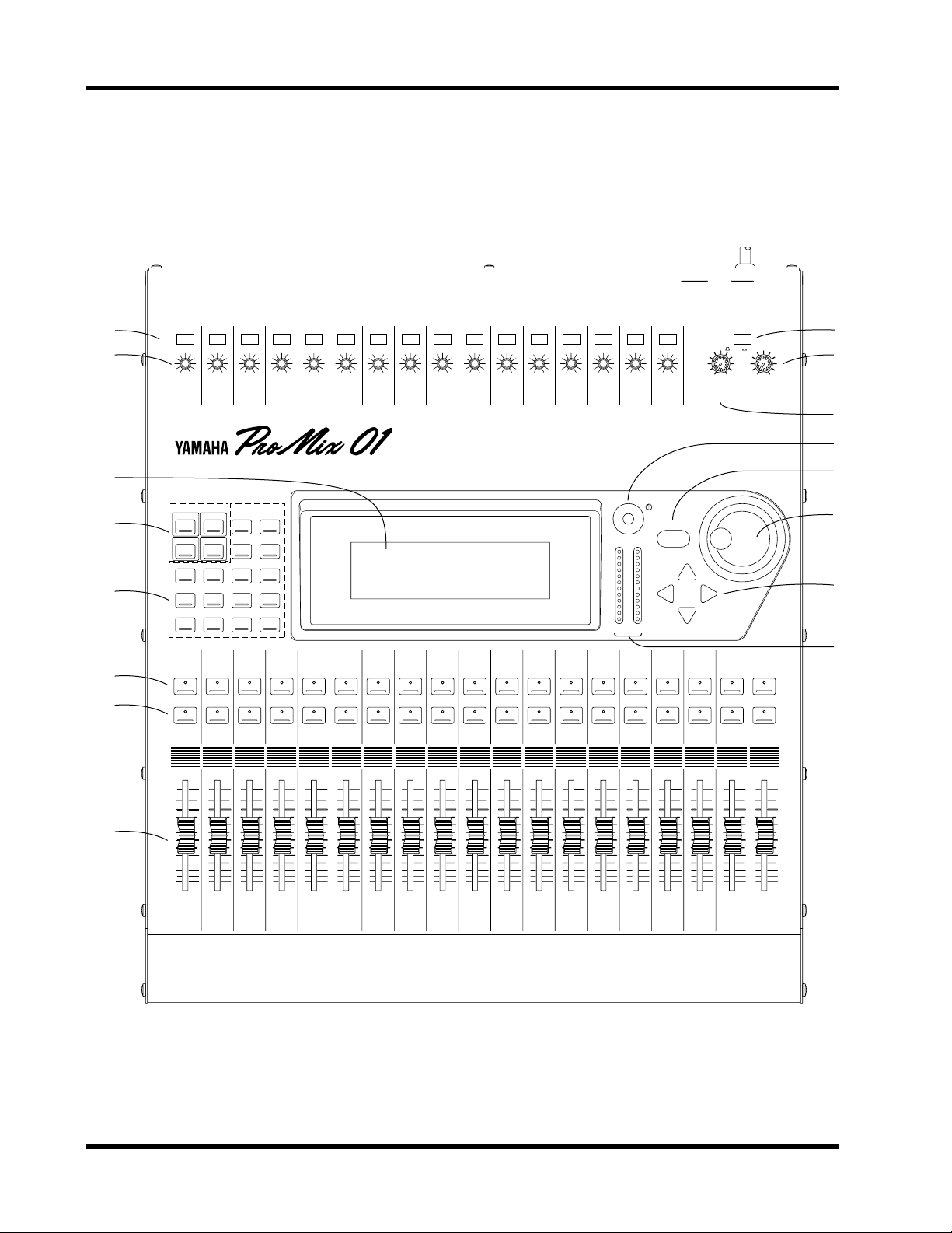
Top Panel
11 12 13 14 15 16
1 2 3 4 5 6 7 8 9
10 LRLR
ST IN
2TR IN
1
2
3
4
5
6
7
PAD
20dB
–16 –60
GAIN
1
SCENE MEMORY
STORE
RECALL
METER
SEND 1
EQ LOW
1
SEL
ON
–16 –60
INC +
DEC –
PAN/ø
MID
GAIN
20dB
20dB
20dB
20dB
20dB
20dB
20dB
20dB
20dB
20dB
20dB
20dB
20dB
20dB
20dB
–16 –60
–16 –60
–16 –60
–16 –60
–16 –60
–16 –60
–16 –60
–16 –60
–16 –60
–16 –60
–16 –60
–16 –60
–16 –60
GAIN
GAIN
GAIN
GAIN
GAIN
GAIN
GAIN
GAIN
GAIN
GAIN
GAIN
2
3
4
5
6
7
8
9
10
11
12
GAIN
13
14
GAIN
–16 –60
GAIN
15
16
010
LEVEL
MONITOR
OUT
CUE/ 2TR IN
010
LEVEL
PHONES
9
0
A
B
PARAMETER
UTILITY
MIDI
GROUP
PAIR
COMP
CUE
2
3
4
HIGH
LIBRARY
2
3
SEL
SEL
ON
ON
FUNCTION
MEMORY
SEL CH
4
5
6
7
8
9
10
SEL
SEL
SEL
SEL
SEL
SEL
ON
ON
ON
ON
ON
ON
11
SEL
SEL
ON
ON
RTN 1
RTN 2
SEND 3
SEND 4
12
13
SEL
ON
14
SEL
SEL
ON
ON
ENTER
CLIP
15
12
9
6
3
0
–6
–12
–18
–24
–40
R
L
15
16
SEL
SEL
ON
ON
ST IN
SEL
ON
RTN/
SEND ST OUT
SEL
SEL
ON
ON
C
D
E
F
6
6
6
6
6
6
0
0
0
0
0
0
5
5
10
10
20
20
40
40
60
60
00
00
5
6
8
5
5
5
10
10
20
20
40
40
60
60
00
00
1
2
5
10
10
20
20
40
40
60
60
00
00
3
4
ProMix 01 User’s Guide
6
6
6
6
6
6
6
6
6
6
6
6
6
0
0
0
0
0
0
0
0
0
0
0
0
5
5
5
5
5
5
5
5
5
5
10
10
10
10
10
10
10
10
20
20
20
20
20
20
40
40
40
40
60
60
00
7
60
00
00
8
9
40
60
60
00
00
10
11
20
40
40
60
60
00
00
12
13
10
20
20
40
40
60
60
00
00
14
15
5
10
10
20
20
40
40
60
60
00
00
16
ST IN
0
5
5
10
10
20
20
40
40
60
60
00
00
RTN/
SEND
ST OUT

Top Panel
1. PAD switches
These switch the input Pad, which attenuates the input signal by
20 dB. See “Pad” on page 18 for more details.
2. GAIN controls
These control the gain of the input preamp. See “Gain” on page 18
for more details.
3. LCD
This is a 240 x 64 dot backlit graphic LCD and it displays the LCD
functions and their parameter values graphically and numerically.
4. SCENE MEMORY buttons
These buttons are used to select, store, and recall mix scenes. See
“Scene Memories” on page 61 for more details.
5. Function buttons
These buttons acces s the v arious L CD functions. The name of the currently sel ected L CD function is s hown in the FUNCTION area on the
L CD.
6. SEL buttons
The S EL buttons are used to select channels. Input channel and stereo
input channel [SEL] buttons select their respective channels. The
R TN/SE ND [SE L ] button, however, is used to selec t SE ND3, S END4,
RTN1, and RTN2. Pressing it repeatedly cycles through the four
options. The currently selected RTN/SEND channel is indicated by
the highlighted arrow at the right side of the L CD. When a channel is
selected, its [SEL] button LED lights up.
3
7. ON buttons
These buttons are used to turn channels ON and OFF. Input channel
and stereo input channel [ON] buttons turn their respective c hannels
ON and OFF. The RTN/S E ND [ON] button, howeve r, is used to turn
S END3, S END4, R TN1, and RTN2 ON and OFF. You must, therefore,
use the RTN/SEND [SEL] button to select the RTN/SEND channel
that you want to turn ON or OFF beforehand. When a channel is ON,
its [ON] button LED lights up. When a channel is turned OFF, the
LED goes OFF.
8. Faders
These are multifunction controls, which means they are used to control more than one signal. They’re motorized, too, which means that
they position themselves automatically when, for example, a mix
scene is recalled, a number of faders are grouped, or an automated
mix via MIDI is play ed back. S ee “Faders” on page 25 for more details.
9. CUE/2TR IN switch
This s witch determines the signal source for the monitor output and
phones. CUE s ele cts the Cue bus, and 2TR IN selects the 2TR IN connection.
Downloaded from:
ProMix 01 User’s Guide

Chapter 1: Touring ProMix 01
4
10.PHONES LEVEL control
This is used to adjust the headphone output level.
11.MONITOR OUT LEVEL control
This is used to adjust the monitor output level.
12.LCD Contrast control
This is used to adjust the L CD contrast. S et it so that the L CD appears
clear and easy to read. You may need to adjust it again when
ProMix 01 warms up or when the LCD is viewed from a different
height or angle.
13.ENTER button
The ex act operation of this button depends on the selec ted L CD function. Essentially, it performs two operations. First, to enter/confirm
settings made using the PARAMETER wheel. Second, to set parameters that have only two options. For example, E Q ON/OFF and Peak
Hold ON/OFF.
14.PARAMETER wheel
This is used to adjust parameter values. Turn it clockwise to increase
a value, and counterclockwise to decrease it.
15.Cursor buttons
These are used to select parameters and options on the LCD.
16.Stereo output meters
These 12-segment LED meters display the stereo output levels. See
“Metering” on page 19 for more details.
ProMix 01 User’s Guide
Downloaded from:

3
Rear Panel
Rear Panel
14
2
PHANTOM
MASTER
CH1~8
ON OFF
(+48V)
(UNBAL)
R
2TR IN
–10dB
+4dB
(UNBAL)
R
ST IN
POWER
ON
L
16 15
OFF
14 13
12 11
PHONES
10
+4dB
(UNBAL)
R
L4
MONITOR OUT
9
+4dB
(UNBAL)
8
7
INPUT
(BAL)
3R
STEREO OUTAUX SEND
+4dB (BAL)
8765
65
ANALOG DIGITAL
–10dB
(UNBAL)
L
RL
9
4
COAXIAL
REC OUT MIDI
3
OUT IN
21
A0
L
5
1. PHANTOM MASTER switch
This switch is used to turn the +48V DC phantom power ON and
OFF. Phantom power is switched simultaneously for input channels
1 through 8.
2. 2TR IN
These are RCA/phono jacks with a –10 dB nominal input level. Signals input here are fed through to the CUE/2TR IN switch and are
monitored via the monitor out and headphones. The outputs of a
2-track master recorder can be connected here for confidence monitoring and playback.
Note:
When no plugs are ins erted into the S T IN phone j a cks , the 2TR
IN s ignals are fed through to the stereo input channel. This means that
you can apply EQ, etc., to the 2 TR IN s i gnals . When plugs are inse r ted
into the ST IN phone jacks, however, this connection is broken.
3. ST IN
These are unbalanced 1/4" phone jacks with a +4dB nominal input
lev e l . Si g nals input here are fe d through to the stereo input channel.
The outputs of an external ef f ects processor, or other device with stereo line-level outputs can be connected here.
When no plugs are inserted, the 2TR IN signals are fed through to the
stereo input channel (see above note).
Downloaded from:
ProMix 01 User’s Guide

Chapter 1: Touring ProMix 01
6
Hot
2
3
Ground
4. INPUT (BAL)
Input channels 1 through 8 have balanced X L R -3-31 type connectors
for connecting microphones. The nominal input level is –60dB to
1
Ground
Cold
Cold
Hot
+4dB. They are wired according to the IEC 268 standard: Pin
1–ground, pin 2–hot (+), and pin 3–cold (–). Phantom powering is
available for condenser type microphones, and it is set using the
PHANTOM MASTER switch.
Input channels 9 through 16 have balanced phone jack connectors.
The nominal input level is –60dB to +4dB. W iring is s le eve–ground,
tip–hot (+), and ring–cold (–). They can be used with balanced or
unbalanced plugs.
Besides connector type and phantom power, the input circuits for
inputs 1 through 16 are the same. So with an adaptor cable, inputs 9
through 16 can also be used with balanced microphones.
Note:
Make sure that the ba lanced devices y ou connect to the INPUTs
als o use pin 2–hot, pin 3–col d wiring. If they’re wired differ e ntly , undesirable phase shifts may occur. Refer to their user manuals for details.
5. POWER switch
This is a push-type power switch. It’s recessed to prevent accidental
operation. Press once to power ON; press again to power OFF.
6. PHONES
This is a stereo (TRS) 1/4" phone jack. A pair of stereo headphones
can be connected here for monitoring. The phones output signal
source is the same as that of the monitor output. The headphone lev el
is set using the PHONES LEVEL control.
7. MONITOR OUT
These are unbalanced 1/4" phone jacks wi th a +4dB nominal output
level. They output the monitor signals, and can be connected to the
inputs on a monitor amplifier. The monitor signal source is determined by the CUE/2TR IN switch and CUE modes. The output leve l
is set using the MONITOR OUT LEVEL control.
8. AUX SEND
These are unbalanced 1/4" phone jacks wi th a +4dB nominal output
level. They output the SEND3 and SEND4 signals, and can be used
to fe ed external eff ects processors, foldback amplifiers, or multitrack
recording equipment.
SEND3 and SEND4 can be configured as a stereo pair. In this case,
an additional pan control on each input channel and a balance control
on the stereo input channel al lows input signals to be panned between
these outputs. Se e “S END3-4 S tereo Pair” on page 46 for more details.
ProMix 01 User’s Guide

Ground
Rear Panel
7
9. STEREO OUT
These are balanced XL R-3-32 type connectors with a +4dB nominal
output level. They are wired pin 1–ground, pin 2–hot (+), and pin
1
3
Hot
2
Cold
3–cold (–).They output the main stereo signals and can be c onnected
to power amplifiers in sound reinforcement applications.
Note:
When the STEREO OUT XLRs are used with unbalanced connec tors , their maximum output leve l is r educ ed b y 6dB. This mea ns that
the STEREO OUT signal actually clips when the 12dB LED lights up,
which is 8dB before the CLIP LED.
10.REC OUT
The ANALOG outputs are RCA/phono jacks with a –10dB nominal
output level . They output the main stereo signals for recording, and
can be connected to cassette and other analog recorders. They can also
be used instead of the XLR STERE O OUTs to connect ProMix 01 to
your home hi-fi system.
The DIGITA L COAX IAL output is an RCA /phono jack. It outputs the
main stereo signals for recording, and can be connected to DAT, MD,
and DCC digital recorders via a 75 ohm coaxial c able. The digital output format is IEC958 (Consumer).
11.MIDI
These are standard MIDI IN and OUT connections. They can be used
to connect a controlling computer or MIDI sequencer for automated
control. They can also be used for control of other ProMix 01s in a
multiple system. See “MIDI” on page 79.
ProMix 01 User’s Guide

ProMix 01 User’s Guide
INPUT
(BAL)
(UNBAL)
(UNBAL)
ST IN
+4dB
2TR IN
–10dB
PHANTOM MASTER (+48V)
CH1–8
CH9–16
L
R
L
R
ON
OFF
20dB
PAD
20dB
HAPAD
GAIN
Same as
CH 1–8
INTERNAL
EFFECT 1
ST
METER
AD
METER
AD
AD
METER
3BAND
ø
PEQ
3BAND
ø
PEQ
3BAND
ø
PEQ
3BAND
PEQ
3BAND
PEQ
COMP
RTN1
FADER
CH FADER
PRE/POST
ON
CUE
ST IN FADER
ON
CUE
ON
PAN
SEND1
SEND2
SEND3
SEND4
DUAL
PAN
SEND1
SEND2
SEND3
SEND4
DUAL
PAN
SEND CUE
L R 1 2 3 4 L R
COMP
COMP
COMP
3BAND
PEQ
3BAND
PEQ
CUE
ST OUT
FADER
ST OUT
BALANCE
SEND3
FADER
ODD/L IN
KEY IN
EVEN/R IN
METER
COMP
DA
COMP
ON
COMP
ON
DA
DA
DA
METER
DA
ENVELOPE
FOLLOWER
FORMAT
CONVERTER
CUE/
2TR IN
COMP (×3)
GAIN
REDUCTION
METER METER
PHONES
LEVEL
MONITOR OUT
LEVEL
OUTPUT
ODD/L OUT
EVEN/R OUT
L
STEREO OUT
+4dB(BAL)
R
ANALOG
L
–10dB
R
(UNBAL)
DIGITAL
COAXIAL
PHONES
L
MONITOR OUT
+4dB(UNBAL)
R
SEND3
+4dB(UNBAL)
REC OUT
ProMix 01 Block Diagram
8
Chapter 1: Touring ProMix 01
INTERNAL
EFFECT2
OSCILLATOR
METER
METER
3BAND
PEQ
3BAND
PEQ
RTN2
FADER
CUE
CUE
SEND4
COMP
ON
ONLEVEL
ASSIGN
ST OUT
SEND3
SEND4
DUAL
PAN
FADER
CUE
METER
COMP
ON
DA
SEND4
+4dB(UNBAL)
Multifunction faders and switches
LCD functions

An A
Mi
ProMix 01 Block Diagram
nalog
xer Analogy
If ProMix 01 had an analog mixer interface, it might look something like this. If you’re familiar with analog
mixers, you may find this illustration reassuring, and the cross references will certainly help you locate information quickly. Remember that ProMix 01 offers a lot more than what’s shown below, i.e., scene memories,
full MIDI control, two internal effects, three dynamics processors...
GAIN kP.18
EQ kP.21
SEND1, 2
kP.30
PRE/POST
kP.32
SEND3, 4
kP.45
PRE/POST
kP.45
P ANkP.26
ONkP.25
CUEkP.50
GROUPkP.56
–16
GAIN
HIGH
MID
LOW
SEND1
SEND2
SEND3
SEND4
PAN
–60
+15–15
+15–15
+15–15
100
100
100
100
CUE
10
20
40
60
∞
RL
ON
6
0
5
EQ ON
PRE/POST
PRE/POST
PRE/POST
PRE/POST
CLIP
+12
–40
A
B
C
D
Pad kP.18Phantom kP.18
Phase kP.20
+48V
20dB
PAD
∅
F
Q
SHELF
PEAK
F
Q
F
Q
SHELF
PEAK
+6
0
G
R
O
U
P
HIGH
MID
LOW
SEND1
SEND2
SEND3
SEND4
DUAL PAN
+15–15
+15–15
+15–15
100
100
100
100
CUE
10
20
40
60
∞
RL
ON
6
0
5
EQ ON
PRE/POST
PRE/POST
PRE/POST
PRE/POST
CLIP
+12
–40
A
B
C
D
∅
F
Q
SHELF
PEAK
F
Q
F
Q
SHELF
PEAK
+6
0
G
R
O
U
P
SEND3, SEND4kP.45
CLIP
+12
+6
0
–40
100
LEVEL
SEND3
DUAL PAN
HIGH
MID
LOW
+15–15
+15–15
+15–15
CUE
10
20
40
60
∞
ON
CUE
F
Q
SHELF
PEAK
F
Q
F
Q
SHELF
PEAK
EQ ON
RL
ON
CLIP
6
+12
+6
0
0
–40
5
LEVEL
SEND4
HIGH
MID
LOW
DUAL PAN
100
+15–15
+15–15
+15–15
CUE
∞
RL
ON
6
0
5
10
20
40
60
MeterskP.19
CLIP
+12
+6
0
–40
ON
CUE
F
Q
SHELF
PEAK
F
Q
F
Q
SHELF
PEAK
EQ ON
CLIP
+12
+6
0
–40
CLIP
15
12
9
6
3
0
–6
–12
–18
–24
–40
LR
100
PHONES
0
10
LEVEL
CUE/2TR IN
MONITOR
+15–15
HIGH
+15–15
MID
+15–15
LOW
RL
BALANCE
ON
CUE
6
0
5
10
20
40
60
∞
CUE/ST FIX
EQ ON
PHONES,
MONITOR
kP.50
CUE/2TR
kP.51
CUEkP.50
F
Q
SHELF
PEAK
F
Q
F
Q
SHELF
PEAK
BalancekP.26
9
RTN1
FaderskP.25
ST OUTRTN2CH1–16 ST IN
ProMix 01 User’s Guide

Chapter 1: Touring ProMix 01
10
ProMix 01 User’s Guide

2
User Interface
User Interface
In this chapter...
About the User Interface . . . . . . . . . . . . . . . . . . . . . . . 12
11
LCD Display . . . . . . . . . . . . . . . . . . . . . . . . . . . . . . . . . 12
Cursor Buttons . . . . . . . . . . . . . . . . . . . . . . . . . . . . . . . 13
PARAMETER Wheel . . . . . . . . . . . . . . . . . . . . . . . . . . 13
ENTER Button . . . . . . . . . . . . . . . . . . . . . . . . . . . . . . . 13
SEL Buttons . . . . . . . . . . . . . . . . . . . . . . . . . . . . . . . . . 14
LCD Functions . . . . . . . . . . . . . . . . . . . . . . . . . . . . . . . 15
Downloaded from:
ProMix 01 User’s Guide

Chapter 2: User Interface
12
About the User Interface
ProMix 01 user interface is straightforward and easy to use. It consists
of a large backlit LCD display, four cursor buttons, a detented
P AR AMETE R w heel, E NTER button, and the channel [S EL ] buttons.
Each of these are ex plained in detail in the following sections. Functions without dedicated controls are organized into LCD functions,
which are selected using the function buttons to the left of the LCD.
LCD Display
The large backlit 240 x 64 dot graphic L CD display provides cl ear indication of mix settings and operating s tatus. As wel l as showing parameter values numerically, faders and rotary controls are represented
graphically , so y ou can actually se e pan positions and fader positions.
In addition, EQ curves are displayed graphically and signal lev el s are
metered. The following ill ustration shows information that is alwa ys
displayed and explains what it means.
The F UNCTION area
shows the name of
the selected LCD
function
The MEMORY area
s hows the current mix
scene name and
number
The SEL CH area
shows the currently
selected channel
FUNCTION
MEMORY
SEL CH
The highlighted arrow
indicates the channel
selected using the
R T N/S END [SEL] button
RTN 1
RTN 2
SEND 3
SEND 4
This icon indicates that
another display is available to the right. When
that display is selected,
the icon moves to the left
side of the display
The following table shows what can appear in the FUNCTION,
MEMORY, and SEL CH areas of the LCD.
LCD Area Displayed
FUNCTION
MEMORY
SEL CH
UTILITY, MIDI, SCENE MEMORY, GROUP, PAIR, METER, PAN/
COMP, CUE , SE ND1, S END2, S END3, SEND4, SEND3-4, E Q, LIBRAR Y
Name and number of the current mix scene: 00 to 50
CH1–CH16, ST IN, RTN1, RTN2, SEND3, SEND4, SEND3-4, ST OUT
∅
,
ProMix 01 User’s Guide

Cursor Buttons
13
Cursor Buttons
The cursor buttons are used to select parameters and options on the
LCD. The selected parameter or option appears highlighted.
Highlighted
The [
√
the [
π
] and [
Cursor buttons are also used to position the cursor in a name when
naming mix scenes, user effects programs, user EQ programs, and
user dynamics programs. They are also used to selec t LCD functions
listed on the UTILITY and MIDI LCD function menus.
When a display lef t or right icon appears at the left or right side of the
display , indicating that another display i s av ailable, the [
cursor buttons are used to select the display.
Display left–right icons.
] and [
®
] cursor buttons move the cursor lef t and right, and
†
] cursor buttons move the cursor up and down.
√
] and [
®
]
ENTER
PARAMETER Wheel
The PARAMETER wheel is used to adjust the parameter selected
using the cursor buttons. Its detented action gives it a positive feel,
allowing quick and accurate parameter adjustments. T urning it clockwise increases the selected parameter value, or turns the parameter
ON. Turning it counterclockwise decreases the selected parameter
value, or turns the parameter OFF. The faster you turn it, the faster
the parameter value changes.
The PARAMETER wheel is also used to scroll through mix scenes,
effects programs, EQ programs, and dynamics processor programs.
When naming mix sc enes, user effe cts programs, user EQ programs,
and user dynamics programs, the PARA ME TER wheel is used scroll
through the available characters.
ENTER Button
The [ENTER] button is used to confirm settings made using the
P ARA METER wheel and to toggle two-option parameters s uch as EQ
ON/OFF and Ef f ec t ON/OFF. It is also used to acces s LCD functions
listed on the UTILITY and MIDI LCD function menus.
ProMix 01 User’s Guide
Chapter 2: User Interface
14
SEL Buttons
SEL
The [SEL] buttons are used in conjunction with the L CD functions.
T o perform an action on a channel, first selec t it using a [S EL ] button,
then choose a function using the function buttons to the left of the
LCD. This form of editing is similar to computer word processing.
First, you select your text, then execute a function.
The input channel, stereo input channel, and stereo output [SEL]
buttons select their respective channels. The RTN/SEND [SEL] button, on the other hand, is used to select RTN1, RTN2, SEND3, and
SEND4. Pressing it repeatedly cycles through the options in the following order:
RTN1—>RTN2— >SEND3—>SEND4—>
When SEND3 and SEND4 are used as a stereo pair, SEND3 and
SEND4 are selected together. The order then becomes:
RTN1—>RTN2—>SEND3-4—>
RTN1, RTN2, SEND3, and SEND4 are selected automatically when
the corresponding [SEND] button is pressed. For example, pressing
[SEND1] selects RTN1 and pressing [SEND3] selects SEND3.
When a channel is selected, its [SEL] button LED lights up and its
name appears in the SEL CH area of the LCD. Stereo-pair channels
are selected together. The channel currently selected by the
R TN/SE ND [SEL] button is indicated by the highlighted arrow head
at the right side of the LCD.
Selected channel
Selected RTN/SEND channel
RTN1
RTN2
SEND3
SEND4
ProMix 01 User’s Guide

LCD Functions
15
LCD Functions
ProMix 01 functions without dedicated controls are organized into
LCD functions. They are selected using the function buttons to the
left of the LCD. The name of the selected LCD function appears in
the FUNCTION area of the display.
The f ollowing table lists al l L CD functions and explains w hat they do.
LCD Function Description
Lists the utility functions: OSCILLATOR, SEND3, 4 CONFIGU-
UTILITY
MIDI
S CENE MEM ORY
GROUP
PAIR
METER
PAN/
∅
COMP
CUE
SEND1
SEND2
SEND3
SEND4
SEND3-4
EQ
LIBRARY
RATION, OUTPUT COMP PATCH P OINT, MEMORY PR OTECT,
and BATTERY CHECK.
Lists the MIDI functions: MIDI SETUP, PR OGRAM CHANGE ASSIGN, CONTROL CHANGE ASSIGN, BULK DUMP/REQUEST,
LOCAL ON/OFF, and MEMORY CONTROL CHANGE OUT.
Store and recall mix scenes.
Set up the four fader groups.
Set up channel pairs.
Meter CH1–16, S T IN, R T N1, RT N2, SEND3, and SEND4 levels.
There are two displays.
Set pan, balance, and phase. There are three displays.
Store, recall, and edit COMP1, COMP2, COM P3.
Set the CUE mode and display channel information.
Store, recall, and edit effects programs for internal Effect 1.
Store, recall, and edit effects programs for internal Effect 2.
Set up SEND3.
Set up SEND4.
This LCD function appears instead of SEND3 and SEND4 in
S END3-4 stereo mode. There are two displays . The s econd dis play contains the channel-to-SEND3-4 pan controls.
Set the EQ.
Store and recall EQ programs.
ProMix 01 User’s Guide

Chapter 2: User Interface
16
ProMix 01 User’s Guide

3
Mixer Functions
Mixer Functions
In this chapter...
Phantom Power . . . . . . . . . . . . . . . . . . . . . . . . . . . . . . 18
17
Pad . . . . . . . . . . . . . . . . . . . . . . . . . . . . . . . . . . . . . . . . . 18
Gain . . . . . . . . . . . . . . . . . . . . . . . . . . . . . . . . . . . . . . . . 18
Metering . . . . . . . . . . . . . . . . . . . . . . . . . . . . . . . . . . . . 19
Phase . . . . . . . . . . . . . . . . . . . . . . . . . . . . . . . . . . . . . . . 20
EQ . . . . . . . . . . . . . . . . . . . . . . . . . . . . . . . . . . . . . . . . . 21
EQ Library . . . . . . . . . . . . . . . . . . . . . . . . . . . . . . . . . . 22
EQ Presets . . . . . . . . . . . . . . . . . . . . . . . . . . . . . . . . . . . 23
Faders . . . . . . . . . . . . . . . . . . . . . . . . . . . . . . . . . . . . . . 25
ON Buttons . . . . . . . . . . . . . . . . . . . . . . . . . . . . . . . . . 25
Pan and Balance . . . . . . . . . . . . . . . . . . . . . . . . . . . . . . 26
Stereo Output Balance . . . . . . . . . . . . . . . . . . . . . . . . . 26
Stereo-Pair Pans . . . . . . . . . . . . . . . . . . . . . . . . . . . . . . 27
Stereo Width . . . . . . . . . . . . . . . . . . . . . . . . . . . . . . . . . 27
Downloaded from:
ProMix 01 User’s Guide

Chapter 3: Mixer Functions
(
)
18
PHANTOM
MASTER
CH1~8
ON OFF
+48V
PAD
20dB
Phantom Power
Phantom power provides a +48V DC power source for condenser
type microphones. It is applied to XLR input channels 1 through 8.
The PHANTOM MAS TE R s witch on the rear panel is used to turn it
ON and OFF. Phantom power is applied simultaneously to all eight
inputs. It cannot be set for individual inputs.
With phantom power set to ON, non-phantom powered microphones, dynamic microphones, and balanced line-level sources can
still be connected to inputs 1 through 8. However, be careful with
unbalanced sources.
Pad
The Pad function attenuates input signals by 20dB. This is useful
when inputting high lev el signals that overload the input preamp. B y
increasing the ef fe ctive range of the GAIN control, high-level s ignals
can be adjusted accurately . Pad can be set individually f or the 16 input
channels. The PAD switch at the top of each channel is used to turn
it ON and OFF: switch up for OFF, down for ON.
–16 –60
GAIN
Gain
The GA IN controls are used to optimize the input channel s ignal levels. Us e them with the METER LCD function, w hich shows the input
signal lev el s. Ideally the level should be set relativ ely high and it’s OK
for it to reach CLIP
back off the GAIN control a little, otherwise signal distortion may
occur. The GAIN control should be set with some care, because if it
is s et too low, the S/N performance wil l s uffer, and if it is s et too high,
unpleasant signal clipping and distortion may occur.
occasionally
. If CLIP is reached often, however,
ProMix 01 User’s Guide
Downloaded from:

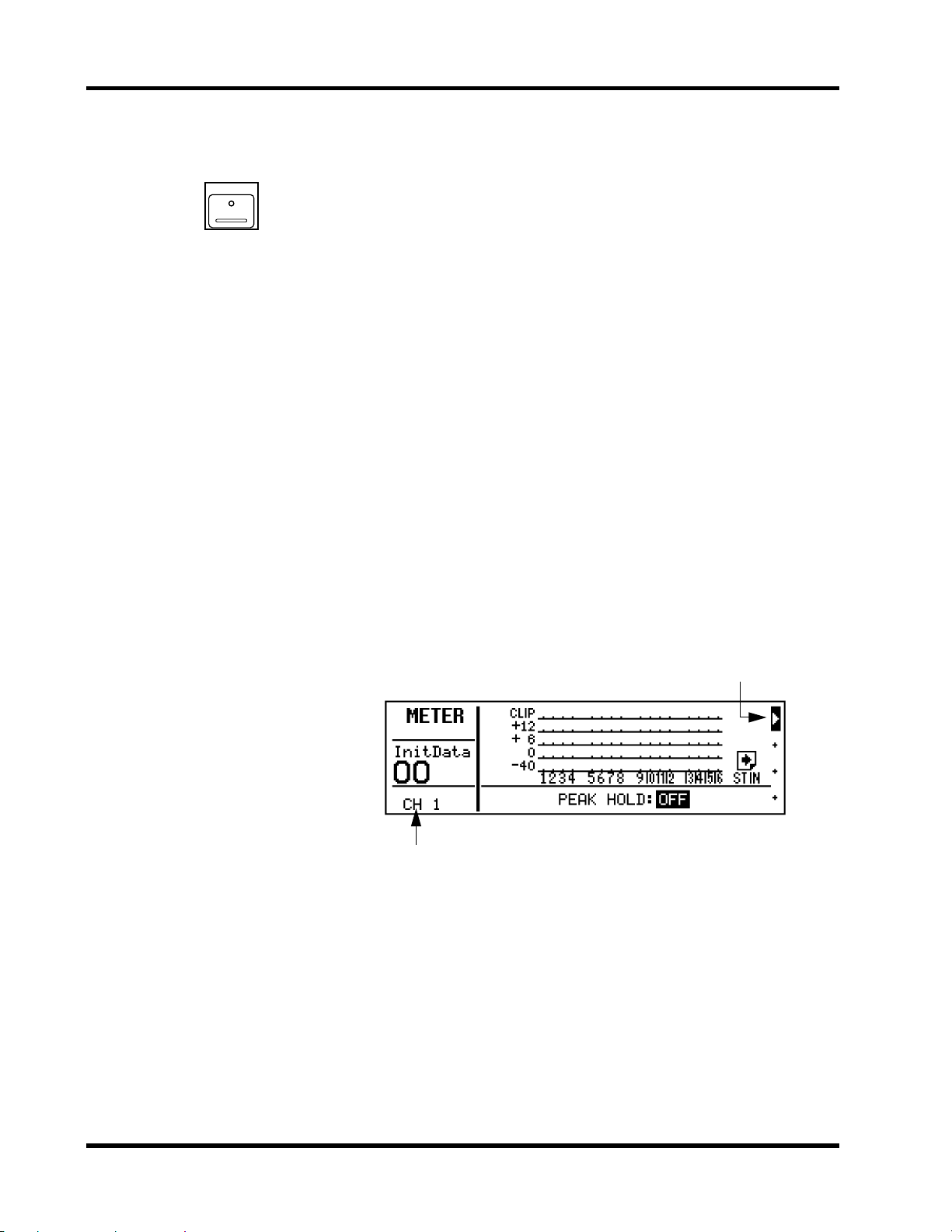
1. Press [METER].
The METER LCD function
appears.
2. To turn the Peak Hold function ON and OFF, press
[E NTE R] or use the PARAMETER wheel.
3. Use the [
√
] [
®
] curs or buttons or press [ENTER] to
switch between the two
METER displays.
Metering
19
Metering
ProMix 01 features comprehensiv e s ignal leve l metering. Input channels , the stereo input channel, R TN1, R TN2, S E ND3, and SE ND4 are
all metered using the METER LCD function. The stereo output is
metered using the dedicated 12-segment LED meters. Peak hold is
available for all meters.
The METER LCD function consists of two displays. One shows the
16 input channels. The other, the stereo input (ST IN), R TN1, R TN2,
SEND3, and SEND4. Both displays are shown below.
CLIP
15
12
9
6
3
0
–6
–12
–18
–24
–40
R
L
Stereo output meters
The Pe ak Hold function can be turned ON and OFF on either display .
Peak hold levels are cancelled when Peak Hold is turned OFF or
another L CD function is se lected. The stereo output meter peak hold
is not affected when other LCD functions are selected.
Note:
It’s OK for signal levels to reach CLIP occasionally. If CLIP is
re ached o ften, ho weve r , ba c k o ff the G AIN c ontro l a little , o therwis e s ig nal distortion may occur.
The following table lists the meter signal source points.
Signal Source Point
Input channel
S tereo input channel (ST IN)
Stereo output
RTN1, RTN2
SEND3, SEND4
Note:
When the STEREO OUT XLRs are used with unbalanced con-
Post GAIN and A/D converter—pre phase and EQ
Post GAIN and A/D converter—pre phase and EQ
Post fader and balance—pre D/A converter
Post internal effect—pre EQ and fader
Post fader—pre D/A converter
nec tors , their maximum output leve l is r educ ed b y 6dB. This mea ns that
the STEREO OUT signal actually clips when the 15dB LED lights up,
which is 5dB before the CLIP LED.
When the stereo output meter’ s 0dB LE D lights up, the DIGITA L REC
OUT still has 20dB of headroom.
Downloaded from:
ProMix 01 User’s Guide

Chapter 3: Mixer Functions
20
Phase
1. Select a channel using the
[SEL] buttons.
2. Press [PAN/
The PHASE LCD function
appears. If the PAN display
appears, press
again.
3. To change the phas e, press
[E NTE R] or use the PARAMETER wheel.
Other channels can be
selected using the
tons or cursor buttons.
∅
].
[PAN/
[SEL]
∅
]
but-
The Phase function reverses the polarity of the hot and cold feeds in
a balanced input (i.e. pins 2 and 3). The phase can be se t for the input
channels and stereo input channel. It can be used to compensate for
incorrectly wi red cables and connectors. It is also useful, f or example,
when a snare drum is miked top and bottom. In this case the bottom
microphone signal needs to be phase reversed.
Shown below is the PHASE LCD function.
The parameters are:
N
—
normal phase.
R
—
reverse phase.
Stereo-pair channels are controlled together, as shown below.
ProMix 01 User’s Guide
EQ
EQ
21
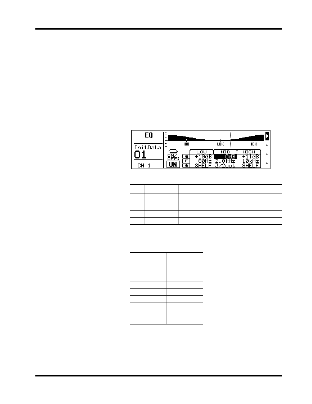
1. Select a channel using the
[SEL] buttons.
2. Press [EQ LOW], [MID], or
[HIGH].
The EQ LCD function appears .
3. Press [EQ LOW], [MID], or
[HIGH] repeatedly to s elec t
the parameters for each
band.
You can also use the cursor
buttons to select parameters.
4. To turn the EQ ON or OFF,
press [ENTER] or select the
ON/ OF F parameter and use
the PARAMETER wheel.
ProMix 01 EQ is three-band fully parametric, with variable Q, frequency, g ain, and ON/OFF parameters. Initially the E Q is configured
as a conventional three-band EQ, with shelving-type low and high
and peaking-type mid. Howev er, high and low can also be configured
as peaking types. EQ can be applied to the inputs channels, stereo
input channel, RTN1, RTN2, and stereo output. Stereo-pair input
channels are controlled together.
Shown below is the EQ LCD function. The top-half shows the EQ
response curve, the bottom-half, the EQ parameters. The v ertical dotted line indicates the frequency of the selected band.
EQ parameters are:
LOW MID HIGH
1/6, 1/4, 1/3,
Q
1/2, 3/4, 1, 3/2,
2, 3 oct, SHELF
F
32 Hz–1 kHz 32 Hz–18 kHz 1 kHz–18 kHz 1/6 octave steps
G
±
15 dB
1/6, 1/4, 1/3,
1/2, 3/4, 1, 3/2,
2, 3 oct
±
15 dB
1/6, 1/4, 1/3,
1/2, 3/4, 1, 3/2,
2, 3 oct, SHELF
±
15 dB 1 dB steps
9 steps
Q is stated in musically intuitive octave values. The following table
compares octave values with conventional decimal Q values.
Octave Q
1/6 8.65
1/4 5.76
1/3 4.32
1/2 2.87
3/4 1.90
1 1.41
3/2 0.92
2 0.67
3 0.40
ProMix 01 User’s Guide
Chapter 3: Mixer Functions
22
EQ Library
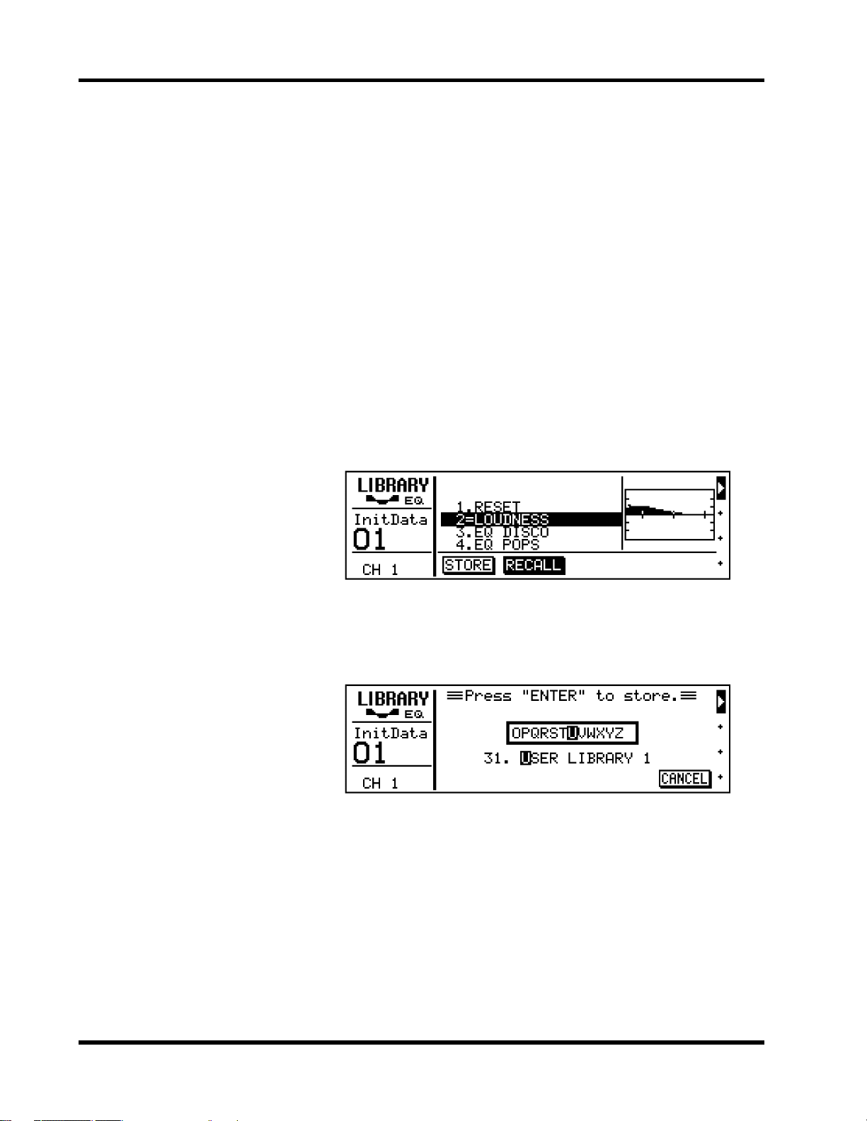
Recalling EQ Programs
1. Select a channel using the
[SEL] buttons.
2. Press [LIBRARY].
The LIBRARY LCD function
appears.
3. Use the PARAMETER wheel
to select an EQ program.
4. Press [ENTER] to recall.
The EQ program is recalled.
Storing EQ Programs
1. Select STORE.
2. Use the PARAMETER wheel
to select an EQ program.
3. Press [ENTER].
The LIB R AR Y NAME L CD function appears.
4. Use the [√] [®] curs or buttons and PARAM ETER
wheel to name the program.
If you want to cancel the store
operation, s elec t CANCEL and
pres s [E NTER ].
The E Q library is used to store EQ settings. Settings are stored as EQ
programs, and there are 30 preset programs (1–30) and 20 user programs (31–50) for you to store your own EQ settings. When ST ORE
is s ele cted on the L IB R A RY LCD function, user program 31, the first
user program, is s ele cted automatically. You cannot select preset programs 1 through 30 w hile the S TORE option is s elec ted. U ser EQ programs can be named for easy identification.
S hown below is the LIBRARY LCD function. The response curve of
the sel ected EQ program is shown to the right. L ibrary programs are
listed in the c enter and the name of the EQ program last recalled or
stored is highlighted. Also there is an equal symbol (=) between the
program’s name and number, not a period like the other programs.
The PARAMETER wheel is used to scroll through the program list.
When another program is selected, its name flashes. If it is recalled,
it stops flashing, appears highlighted, and the period between its
name and number changes to an equal symbol (=).
Shown below is the MEMORY NAME LCD function. The selected
character in the name is highlighted. Available characters scroll
through the box in the center. Us e the cursor buttons to position the
cursor in the name and the P A RA METE R wheel to sc roll through the
characters.
5. Press [ENTER] to store.
The EQ program is stored.
! The preset EQ programs pro-
vide a good starting point and
reference for making adjustments.
ProMix 01 User’s Guide
EQ program names can be up to 15 characters long and the following
characters are available.
ABCDEFGHIJKLMNOPQRSTUVWXYZ
abcdefghijklmnopqrstuvwxyz
()[]{}<>#$%&@!?+-*/÷=– ,.:;",ÙÛ
--
◊
0123456789
Spaces are available between the above character rows.
 Loading...