

Page 1

PM1D System Software V1.6
Supplementary Manual
EE
Page 2

2
PM1D System Software V1.6 Supplementary Manual
Copyright
Copying or distributing this manual in part or in whole using any method without the written permission of
Yamaha Corporation is prohibited.
Tr a de marks
Company names and product names are trademarks and registered trademarks of their respective owners.
Symbols such as ® and TM are not explicitly given in this document.
The illustrations and LCD screens as shown in this owner’s manual are for instructional purposes only, and may
appear somewhat different from those on your instrument.
Page 3

Contents
Contents
Additions and changes in V1.6 . . . . . . . . . . . . 4
Improvements to functions that were added
in V1.5 . . . . . . . . . . . . . . . . . . . . . . . . . . . . . . 5
Panel Assign in the ST IN block . . . . . . . . . . . 5
Panel display of the unit name . . . . . . . . . . . 7
Channel name area added to the EQ CH and
LCR screens. . . . . . . . . . . . . . . . . . . . . . . . . . . 8
Channel name area. . . . . . . . . . . . . . . . . . . . 8
DCA Auto Naming function. . . . . . . . . . . . . . . 9
DCA auto naming procedure . . . . . . . . . . . . 9
Input Channel Auto Naming function. . . . . . 11
Input Channel Auto Naming procedure . . . 11
Pan Nominal Position. . . . . . . . . . . . . . . . . . . 13
Pan Nominal Position procedure . . . . . . . . . 13
DCA Unity. . . . . . . . . . . . . . . . . . . . . . . . . . . . 14
DCA Unity procedure . . . . . . . . . . . . . . . . . 14
Scene Link Event . . . . . . . . . . . . . . . . . . . . . . 15
Scene Link Event procedure . . . . . . . . . . . . 15
Selective Recall . . . . . . . . . . . . . . . . . . . . . . . . 18
File transfer mode . . . . . . . . . . . . . . . . . . . . . .47
Additional preference items . . . . . . . . . . . . . .48
Preset Effects Programs (added in V1.6) . . . .49
Effects Parameters (added in V1.6). . . . . . . . 49
Scene Memory/Effect Library to Program
Change Table. . . . . . . . . . . . . . . . . . . . . . . . .50
MIDI control change NRPN (Non Registered
Parameter Number) assignment table . . . . 50
MIDI Data Format . . . . . . . . . . . . . . . . . . . . . .53
Extended functionality for Recall Safe. . . . . . 21
Recall Safe is now possible for compressor
and gate . . . . . . . . . . . . . . . . . . . . . . . . . . 21
Clear Library. . . . . . . . . . . . . . . . . . . . . . . . . . 22
Extended functionality for the attenuators. . 23
Global Channel Copy . . . . . . . . . . . . . . . . . . . 24
CH COPY screen . . . . . . . . . . . . . . . . . . . . . 24
Using the Global Channel Copy function . . 25
Input Meter Bridge . . . . . . . . . . . . . . . . . . . . 27
FIXED CH mode . . . . . . . . . . . . . . . . . . . . . 28
FOLLOW PANEL mode . . . . . . . . . . . . . . . . 31
Parameter Lock/Console Lock . . . . . . . . . . . . 33
SECURITY screen . . . . . . . . . . . . . . . . . . . . . 33
Setting the System Password/Console
Password. . . . . . . . . . . . . . . . . . . . . . . . . . 34
Parameter Lock . . . . . . . . . . . . . . . . . . . . . . 35
Console Lock . . . . . . . . . . . . . . . . . . . . . . . 36
Surround panning . . . . . . . . . . . . . . . . . . . . . 37
SURR PRM screen . . . . . . . . . . . . . . . . . . . . 37
Internal settings and operation in surround
mode . . . . . . . . . . . . . . . . . . . . . . . . . . . . 40
Making surround pan settings. . . . . . . . . . . 43
Cautions regarding surround pan . . . . . . . . 45
Multi-band dynamics processor. . . . . . . . . . . 46
3
Page 4

4
PM1D System Software V1.6 Supplementary Manual
This supplementary manual explains the functionality that has been added or changed in PM1D system software V1.6. Please use this manual in conjunction with the existing manuals.
*In cases where the console (CS1D) display differs from the screen of the PM1D Manager application program, expla-
nations that apply only to the PM1D Manager are distinguished by an indication of [PM1D Manager].
Additions and changes in V1.6
The additions and changes made in PM1D system software V1.6 are summarized below. For details on each
function, refer to the corresponding page.
■
Improvements to functions that were
added in V1.5 (
Of the new functions that were added in V1.5, “Panel
Assign” and “Unit Name” have been improved.
■
Channel name area added to the EQ
CH and LCR screens (
An area that displays the channel names has been
added to the EQ CH screens of the IN EQ function,
and to the LCR screen of the PAN/ROUTING.
■
DCA Auto Naming function (
The DCA [NAME] indicator in the DCA GROUP
block can now be made to display the channel names
of the two last-assigned channels.
■
Input Channel Auto Naming function
(
→
p.11)
You can now make the INPUT block INPUT
[NAME] indicator always display the port name.
■
Pan Nominal Position (
You now have the option of specifying that paired
input channels (or ST IN channels) will be at nominal level (0 dB) when panned to far left or right.
■
DCA Unity (
When cue-monitoring a DCA group, it is now possible to always monitor the unity-level signal regardless of the state of the DCA fader or DCA [MUTE]
switch.
■
Scene Link Event (
You can now cause a pre-programmed string of
MIDI events to be output from the desired MIDI
OUT connector when a specific scene is recalled.
■
Selective Recall (
A Selective Recall function has been added, allowing
you to specify for each scene, parameters/channels
that will be excluded from recall when that scene is
recalled.
■
Extended functionality for Recall Safe
(
→
p.21)
The Recall Safe function has been extended, resulting
in slight changes to the Recall Safe screen, and adding parameters that can be set to Recall Safe.
→
→
p.5)
p.14)
→
→
→
p.15)
p.18)
p.8)
→
p.13)
→
p.9)
■
Clear Library (
A CLEAR button has been added to each library
screen, allowing you to erase a library as desired.
■
Extended functionality for the attenuators (
→
p.23)
The functionality of the input channel attenuators
has been expanded to allow cut/boost in a range of
–96 to +24 dB.
■
Global Channel Copy (
Now you can choose desired parameters from the
currently selected channel, and copy them to multiple channels of the same type in a single operation.
■
Input Meter Bridge (
The levels of input channels and ST IN channels can
now be displayed in the meter bridge.
■
Parameter Lock/Console Lock (
By specifying a password, the user can prevent certain parameters from being edited until the correct
password is input, or prohibit console operations.
■
Surround panning (
Surround Pan functionality has been added, allowing
sounds from an input channel to be placed in a twodimensional space when a multi-channel playback
system is used.
■
Multi-band dynamics processor (
A multi-band dynamics processor that includes an
independent compressor for each of three bands has
been added as an effect type for the internal effects.
■
File transfer mode (
Data saved on a computer in which PM1D Manager
is installed can now be uploaded to the console, and
CS1D settings can be downloaded to the computer.
■
Additional preference items (
The following items have been added to the UTILITY function PREFERENCE screen.
•
PROHIBIT DCA ASSIGN ON SELECTED CH
BLOCK
•
SKIP CONFIRMATIONS FOR MIX MINUS
SHORTCUT
•
LIBRARY PROTECTION
→
p.22)
→
→
→
→
p.27)
p.37)
p.47)
p.24)
→
→
→
p.48)
p.33)
p.46)
Page 5
Improvements to functions that were added in V1.5
Improvements to functions that were added in V1.5
The following improvements have been made to the new functions that were added in V1.5.
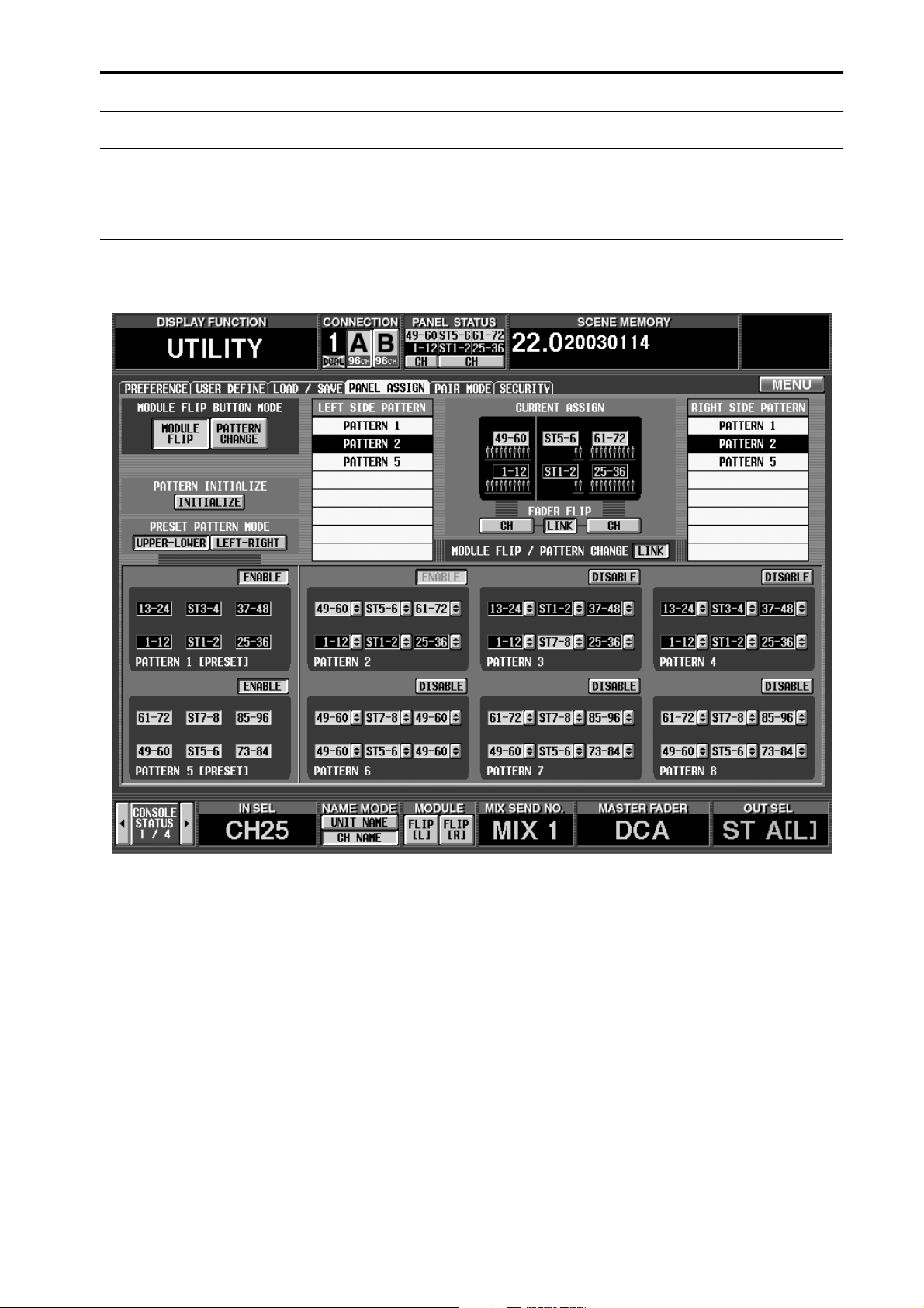
Panel Assign in the ST IN block
In V1.5, a PANEL ASSIGN screen was added to the UTILITY function, allowing the combination of input channels and
ST IN channels reflected in the panel to be specified for each individual block.
5
Page 6
PM1D System Software V1.6 Supplementary Manual
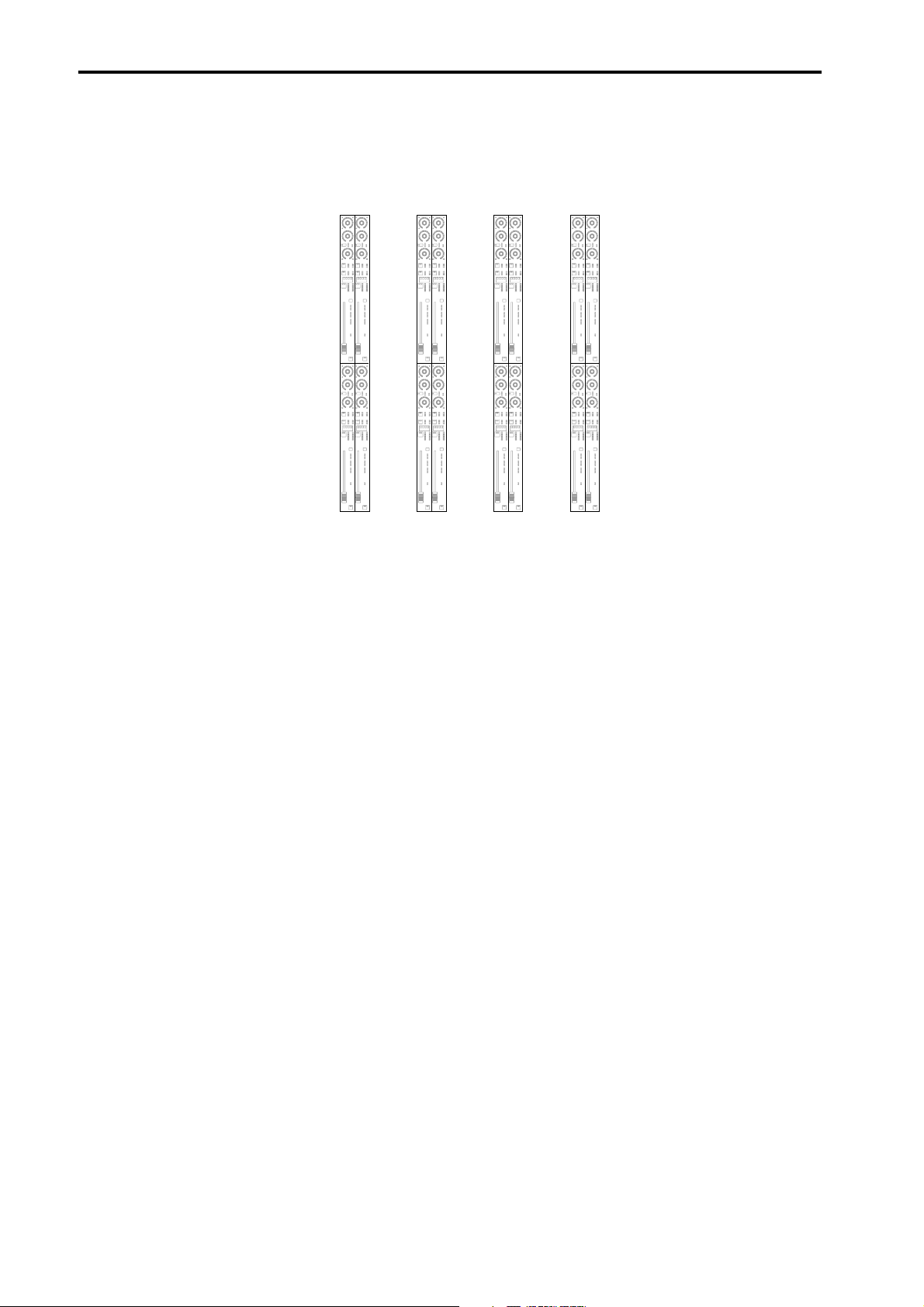
However for ST IN channels, the combinations that could be assigned to the panel were limited to the following four
possibilities.
•
The four combinations that were possible in V1.5
ST IN
block 2
ST IN
block 2
ST IN
block 2
ST IN
block 2
34
12
ST IN
block 1
12
34
ST IN
block 1
78
56
ST IN
block 1
56
78
ST IN
block 1
This limitation has been removed in V1.6. For example, any two ST IN channels of consecutive number such as ST IN
channels 1/2 and 5/6, or 1/2 and 7/8, can be combined freely. Also, if necessary, you may assign combinations of the same
ST IN channel to upper and lower ST IN blocks; e.g., ST IN channels 1/2 and 1/2, or ST IN channels 5/6 and 5/6.
6
Page 7
Improvements to functions that were added in V1.5
Panel display of the unit name
In V1.5, the UNIT NAME screen added to the SYS/W.CLOCK function allowed you to assign a name to each port of each
input/output unit or card. In addition, if you turned on the UNIT NAME button in the NAME MODE area at the bottom of the screen, the name of the port assigned to that channel would be displayed instead of the short name of the
input channel shown in the screen.
In V1.6 when you turn on the UNIT NAME button in the NAME MODE area, the INPUT [NAME] indicator in the
INPUT block will also show the name of the port assigned to that channel.
• INPUT block
Port name
SEL
+
THR
-
COMP
+
THR
-
GATE
CLIP
12
18
30
60
+
THR
-
COMP
+
THR
-
GATE SEL
SEL
6
CLIP
6
12
18
30
60
+
THR
-
COMP
+
THR
-
GATE SEL
CLIP
6
ONONONON
12
18
30
60
+
THR
-
COMP
+
THR
-
GATE
CLIP
12
18
30
60
6
7
Page 8
PM1D System Software V1.6 Supplementary Manual
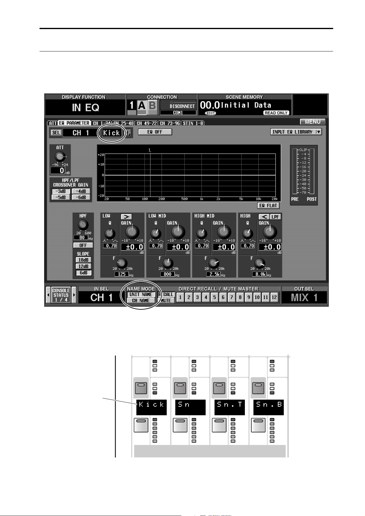
Channel name area added to the EQ CH and LCR screens
An area that displays the channel name of each channel has been added to the EQ CH screens (CH 1-24, CH
25-48, CH 49-72, CH 73-96, ST IN 1-8) of the IN EQ function and to the LCR screen of the PAN/ROUTING
function.
Channel name area
If the CH NAME button located in the NAME MODE area at the bottom of the display is turned on, this area will show
the short name of the corresponding channel.
•
EQ CH screen
•
LCR screen
Short name of the input channel
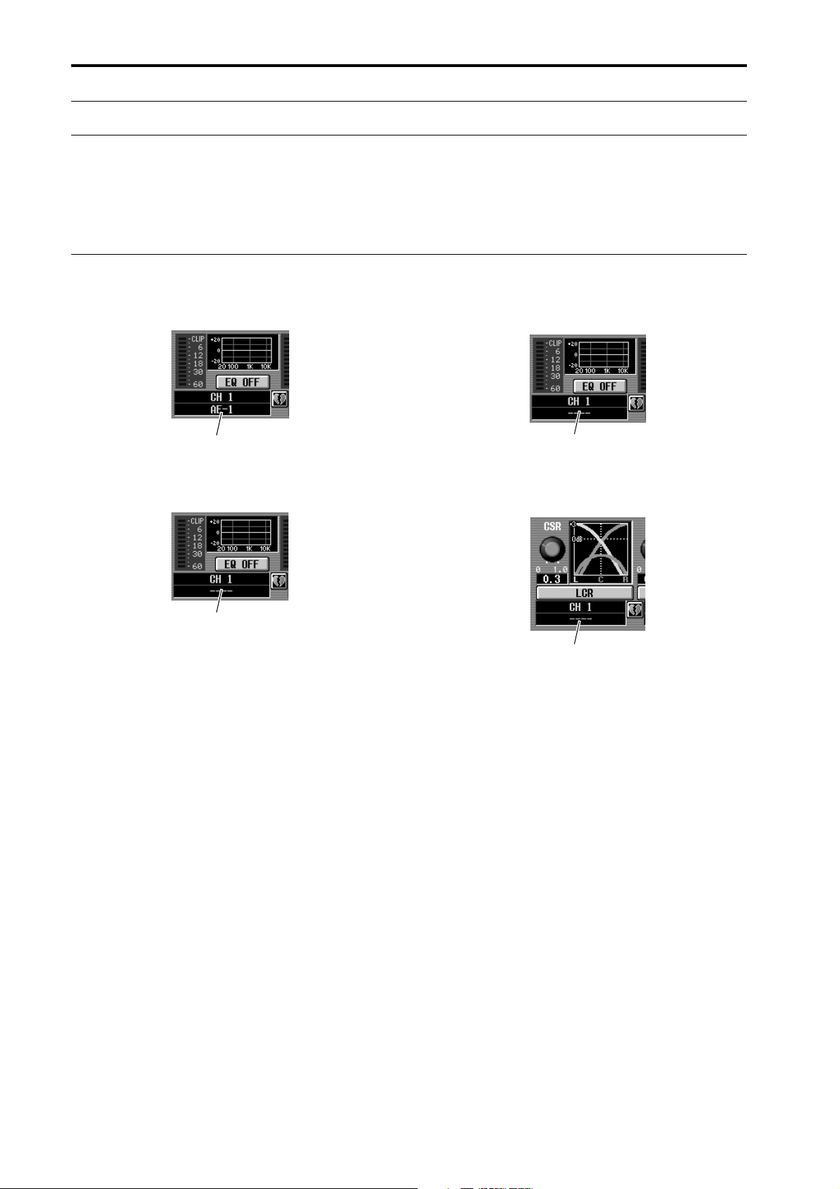
When the UNIT NAME button is on, the name of the port assigned to that channel will be displayed.
•
EQ CH screen
Port name of the input channel
•
Short name of the input channel
LCR screen
Short name of the input channel
8
Page 9
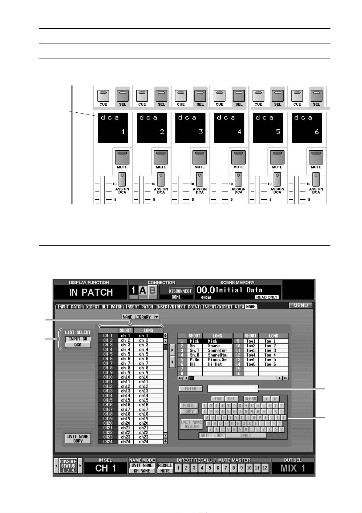
DCA name
DCA Auto Naming function
DCA Auto Naming function
Normally, the DCA [NAME] indicator in the DCA GROUP block will display the name assigned to each DCA
group.
In V1.6, the channel names of the last-assigned two channels can also be displayed in the DCA [NAME] indicator. (This is called the “DCA auto naming function.”)
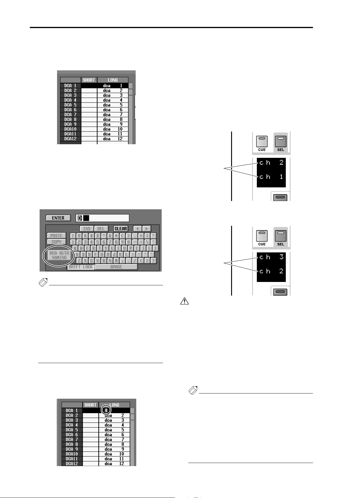
DCA auto naming procedure
The auto naming procedure is as follows.
1. Access the IN PATCH/OUT PATCH function NAME
screen.
2
1
3
4
9
Page 10
PM1D System Software V1.6 Supplementary Manual
2. In the LIST SELECT area ( 1 ), move the cursor to
the DCA button and press the [ENTER] switch.
The name list ( 2 ) will show a list of the long names
(eight characters) assigned to each DCA group.
3. In the name list, move the cursor to the column of
the desired DCA group.
4. Make sure that the cursor is located at the first
character of the text box ( 3 ) at right, and click the
DCA AUTO NAMING button of the character palette ( 4 ).
A highlighted “D” character will be input into the
character palette.
The Auto Naming function is now enabled for the
corresponding DCA group. At this time, the DCA
[NAME] indicator will go dark if a channel has not
been assigned to the corresponding DCA group.
6. As necessary, perform the same operation for other
DCA groups.
7. Assign channels to the DCA groups for which you
performed steps 3–6.
For example if you assign input channels 1 and then
2 to DCA group 1, the corresponding DCA [NAME]
indicator will show the channel names of input channels 1/2.
Channel
names
If you then add input channel 3 to the same DCA
group, the DCA [NAME] indicator will change as
follows.
Hint
• If a PS/2 keyboard is connected to the CS1D, you
can also type Ctrl + D to input the highlighted “D”
character. (As a shortcut, you can hold down the
Ctrl key and type the first character of the button
name in the character palette.)
• When you input the highlighted “D,” no further
characters can be input into the text box. Also, any
previously-input characters will be deleted.
• To delete the highlighted “D,” click the CLEAR
button.
5. Click the ENTER button at the right of the character palette.
A highlighted “D” character will be input in the long
name field of the name list.
Channel
names
• Be aware that when you use the DCA Auto Nam-
ing function, the DCA [NAME] indicator will
show the short names of the two last-assigned
channels.
• A maximum of twelve channels of names will be
remembered for a DCA group. If a paired channel is assigned, the lower-numbered channel will
be displayed above.
• If you remove input channel 3 from DCA group 1
in the example described above, the display will
be blank.
Hint
• If you turn on the UNIT NAME button in the
NAME MODE area at the bottom of the screen,
the DCA [NAME] indicator will show the name of
the port assigned to that channel, instead of showing the short name of the input channel.
• If you turn Cue Monitor on for a DCA group for
which Auto Naming is enabled, the channel that
was last assigned to that DCA group will be
selected (its [SEL] key will light).
10
Page 11
Input Channel Auto Naming function
Input Channel Auto Naming function
As explained earlier, V1.5 added the capability of displaying the channel name or port name in the INPUT
[NAME] indicator of the INPUT block.
However if necessary, it is also possible to specify that the patched port name be always displayed as the input
channel name for only a specific input channel. This is referred to as the “Input channel auto naming function.”
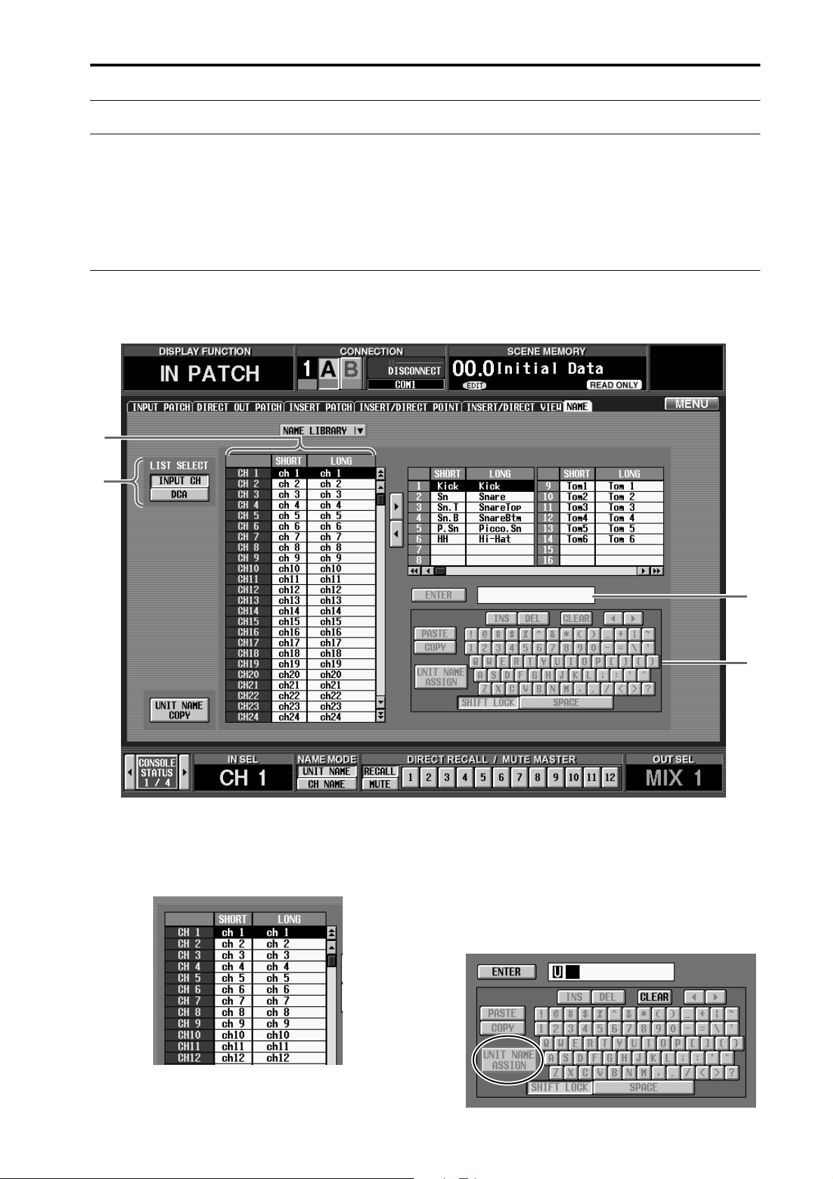
Input Channel Auto Naming procedure
The auto naming procedure is as follows.
1. Access the IN PATCH/OUT PATCH function NAME
screen.
2
1
2. In the LIST SELECT area (1), move the cursor to
the INPUT button and press the [ENTER] switch.
The name list (2) will show a list of the short names
(four characters) and long names (eight characters)
assigned to each input channel.
3
4
3. In the name list, select the desired input channel,
and move the cursor to the short name field.
4. Make sure that the cursor is located at the first
character of the text box (3) at right, and click the
UNIT NAME ASSIGN button of the character palette (4).
A highlighted “U” character will be input into the
character palette.
11
Page 12
PM1D System Software V1.6 Supplementary Manual
Hint
• If a PS/2 keyboard is connected to the CS1D, you
can also type Ctrl + U to input the highlighted “U”
character. (As a shortcut, you can hold down the
Ctrl key and type the first character of the button
name in the character palette.)
• When you input the highlighted “U,” no further
characters can be input into the text box. Also, any
previously-input characters will be deleted.
• To delete the highlighted “U,” click the CLEAR
button.
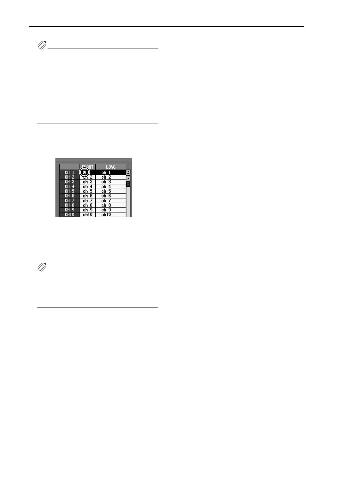
5. Click the ENTER button at the right of the character palette.
A highlighted “U” character will be input in the short
name field of the name list.
The Auto Naming function is now enabled for the
corresponding input channel. Now the port name
assigned to the channel will always be displayed in
areas of the screen that display the short name of the
corresponding channel, and in the corresponding
INPUT [NAME] indicator of the panel.
Hint
It is also possible to select the long name field instead
of the short name field in step 3. In this case, the port
name will always be displayed in areas of the screen
that display the long name of the corresponding
channel.
12
Page 13

Pan Nominal Position
Pan Nominal Position
Normally if a signal sent from an input channel to the stereo bus is panned to the far-left or far-right position,
the level will increase by +3 dB compared to when the signal is panned to the center. This is done so that a
constant volume (energy) will be output whether the signal is mono or stereo; however when inputting a stereo source such as a synthesizer or CD player, you may consider this an inconvenience.
Thus, V1.6 adds the option of specifying that only paired input channels (or ST IN channels) will be at nominal level (0 dB) when pan is set to far left or right.
Pan Nominal Position procedure
Use the following procedure to enable this option.
1. Access the PAN/ROUTING function CH to MIX
screen.
The PAN NOMINAL POSITION field has been
added to this screen.
• CENTER .........If this button is on, all input chan-
nels and ST IN channels will be at
nominal level (0 dB) when panned
to the center, and +3 dB when
panned fully left or right. (This is
the default setting.)
• L ⇔ R.............. If this button is on, paired input
channels and ST IN channels will
be at –3 dB when panned to the
center, and at nominal level when
panned fully left or right (L63 or
R63).
2. Move the cursor to the L ⇔ R button and press the
[ENTER] switch.
A popup window will ask you to confirm the
changed Pan Nominal setting.
3. Move the cursor to the OK button and press the
[ENTER] switch.
4. Enable pairing for the desired channels, and make
sure that a mode other than BALANCE is selected
as the pan mode.
In this state, panning fully left or right will produce a
nominal level only for paired input channels and for
ST IN channels.
• Pan Nominal Position does not affect unpaired
monaural input channels.
• Even in the case of a paired input channel (or a
ST IN channel), this setting has no effect if the
pan mode is set to BALANCE.
• In the case of L-MONO or R-MONO, this setting
has no effect; however in the LR-MONO state,
changes in the Pan Nominal Position setting will
be valid.
• When you change the Pan Nominal Position set-
ting, the MIX SEND PAN of signals being sent to
paired MIX buses will also be switched.
• The Pan Nominal Position of each input channel
can be viewed in the graph in the PAN/ROUTING function LCR screen.
Hint
By setting Pan Nominal Position to L ⇔ R, you can
minimize changes in level that occur when a paired
channel is switched between PAN, BALANCE, LMONO, R-MONO, or LR-MONO.
13
Page 14
PM1D System Software V1.6 Supplementary Manual
DCA Unity
When cue-monitoring a DCA group, it is now possible to always monitor the unity-level signal.
In previous versions, even when you pressed the DCA [CUE] switch, you could not monitor the signal of a
DCA group whose DCA fader was lowered or whose DCA [MUTE] switch was on.
However in V1.6, you have the option of always monitoring the DCA group at unity level (the level equivalent
to setting the DCA fader at 0 dB).
DCA Unity procedure
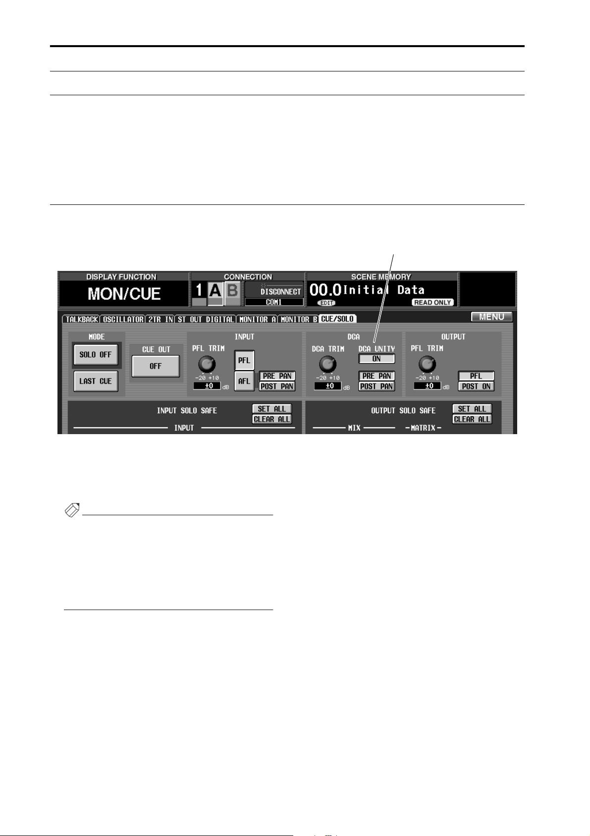
To use this option, access the MONI/CUE function CUE/SOLO screen, and turn on the DCA UNITY ON/OFF button
that has been added to the DCA area.
DCA UNITY ON/OFF button
If this button is on, pressing the DCA [CUE] button
allows you to monitor that DCA group at unity level,
regardless of the current position of the DCA fader or
the on/off state of the DCA [MUTE] switch.
Hint
• The setting of the DCA UNITY ON/OFF button
does not affect the individual channels included in
the DCA groups.
• If the fader of a channel included in the DCA
group is lowered or if its [ON] switch is turned off,
you will not be able to monitor that channel via the
DCA group.
14
Page 15
Scene Link Event
Scene Link Event
You can now cause a string of MIDI events to be output from the desired MIDI OUT connector when a specific scene is recalled. (This is called the “Scene Link Event” function.)
By using this function to pre-program MIDI events for each scene, you can modify the internal settings of an
external device when that scene is recalled, or automatically start the transport of an external device.
Scene Link Event procedure
Here’s how to program MIDI events for each scene.
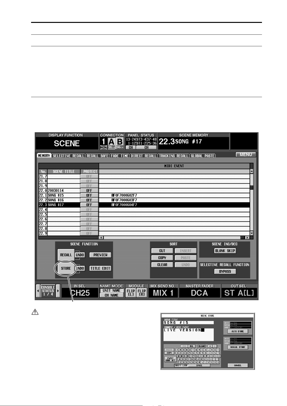
1. Access the SCENE function MEMORY screen.
2. In the list, click the row for the desired scene to
select it.
STORE button
You cannot program MIDI events for a READ
ONLY scene or a protected scene.
3. Click the STORE button in the lower left of the
screen.
The SCENE STORE popup window will appear,
allowing you to assign a title or comment and store
the scene.
15
Page 16

PM1D System Software V1.6 Supplementary Manual
4. Click the COMMENT/MIDI EVENT field to select
it.
The EVENT CODE SET button will appear at the
lower left of the character palette.
COMMENT/MIDI EVENT field
5. Click the EVENT CODE SET button.
The characters in the COMMENT/MIDI EVENT
field will be erased, and a highlighted “M” character
will be input in their place. Also, the characters in the
character palette will be grayed-out except for 1, 2,
and E, and will be unavailable for input.
The highlighted numeral or “E” character will be
added to the COMMENT/MIDI EVENT field. Also,
characters in the characters palette other than 0–9
and A–F will be grayed-out, and will be unavailable
for input.
7. Use the 0–9 and A–F characters of the character
palette to directly input the MIDI event in hexadecimal format.
Tw o hexadecimal characters correspond to one byte
of the MIDI message.
Hint
• If a PS/2 keyboard is connected to the CS1D, you
can also type Ctrl + E to input the highlighted “M”
character. (As a shortcut, you can hold down the
Ctrl key and type the first character of the button
name in the character palette.)
• To erase the highlighted “M,” click the CLEAR but-
ton.
6. Click either 1, 2, or E in the character palette to
select the MIDI OUT connector from which the
MIDI event will be output.
The numerals or “E” character correspond to the following MIDI OUT connectors.
• 1....................... MIDI OUT connector of console 1
• 2....................... MIDI OUT connector of console 2
(if using Dual Console mode)
• E ...................... MIDI OUT connector of the
engine
8. When you have finished inputting the MIDI event,
click the AUTO STORE button or the MANUAL
STORE button.
The MIDI event you input will be stored in the scene.
You can check the contents of the MIDI event by
scrolling to the right edge of the scene list in the
MEMORY screen.
When you recall this scene, the MIDI event will be
transmitted from the specified MIDI OUT connector.
• The PM1D system is in no way aware whether the
MIDI message you input is a valid one. Please use
care when inputting the message.
• You can input a maximum of 32 bytes into the
COMMENT/MIDI EVENT field, calculated as
follows. Since a total of two bytes are used by the
highlighted “M” and the character that specifies
the output destination, you can input a maximum of 30 bytes of MIDI data here.
[Calculation method]
• One comment character .....................1 byte
• Highlighted “M” ..................................1 byte
• Highlighted “1”.................................... 1 byte
• Highlighted “2”.................................... 1 byte
• Highlighted “E” ................................... 1 byte
• Tw o characters of the MIDI message .1 byte
16
Page 17

• It is possible to input two or more messages, as
long as the total stays within 32 bytes. However
you should be aware that, depending on the type
of message, the receiving device may not be able
to process MIDI events received in immediate
succession.
• If you input more than 32 bytes, a warning of
“LENGTH OVER!” will be displayed, and you
will not be able to press the STORE button.
Delete characters until the warning is no longer
displayed.
• You cannot input “FE” (Active Sensing) as a
MIDI code.
• While inputting the MIDI event, you can click
the EVENT CODE SET button and insert the
event that specifies the output destination. This
lets you output events to different MIDI OUT
connectors.
• ƒEven if you recall a scene for which a fade time is
set, the MIDI event will be transmitted immediately after the scene is recalled.
Scene Link Event
17
Page 18
PM1D System Software V1.6 Supplementary Manual
Selective Recall
In V1.6 you can restrict the parameters/channels that will be recalled when a specific scene is recalled, or conversely specify parameters/channels that will be excluded from the recall operation for a specific scene. (This
function is called “Selective Recall.”)
In previous versions, you could use a function called Recall Safe to select channels/parameters that would be
excluded from recall operations. These Recall Safe settings are global, and are common to all scenes. (Channels/parameters excluded from a recall operation do not change when any scene is recalled.) In contrast, the
Selective Recall function lets you store – for each scene – a combination of parameters/channels that will be
recalled, or conversely a combination of parameters/channels that will be excluded from the recall operation.
This lets you create partial scene images for store/recall, using them in a way similar to libraries.
So that you can universally enable/disable the Selective Recall function settings saved in each scene, a BYPASS
button has been added to the MEMORY screen SELECTIVE RECALL FUNCTION area.
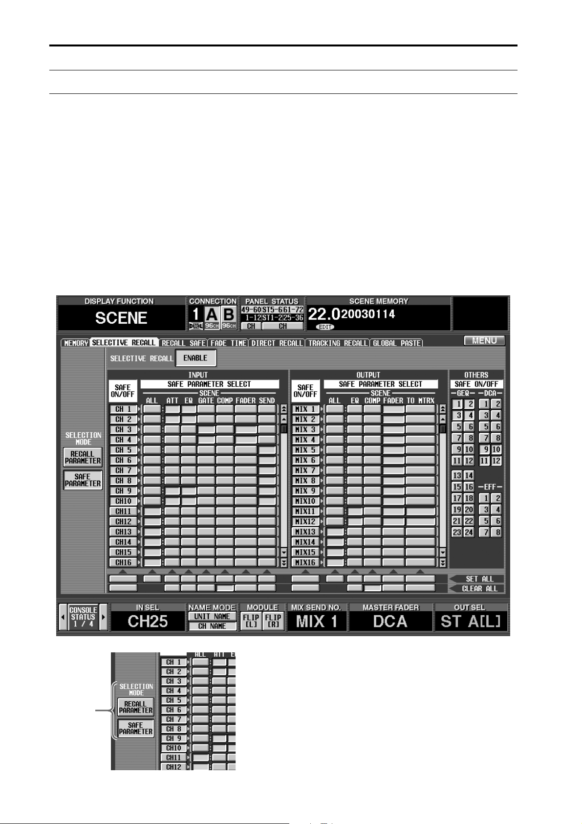
V1.6 adds a SELECTIVE RECALL screen to the SCENE function, allowing you to make Selective Recall settings.
1
18
1 SELECTION MODE
Use the following two buttons to select how you want
to use the SELECTIVE RECALL screen.
• RECALL PARAMETER button
If this button is on, you can use the buttons in the
screen to select the channels/parameters that will be
affected by a recall operation.
• SAFE PARAMETER button
If this button is on, you can use the buttons in the
screen to select the channels/parameters that will be
excluded from a recall operation.
Page 19

Selective Recall
5
6
7
Hint
Each time you switch between the RECALL PARAMETER button and the SAFE PARAMETER button,
the settings in the screen will be initialized as follows.
• When you switch to the RECALL PARAMETER
button, all channels will be set to RECALL ON/
OFF button = On and RECALL PARAMETER
SELECT = ALL.
• When you switch to the SAFE PARAMETER but-
ton, all channels will be set to SAFE ON/OFF button = Off and SAFE PARAMETER SELECT = ALL.
2
3
2 ENABLE/DISABLE button
This button enables (button indicates ENABLE) or
disables (button indicates DISABLE) the Selective
Recall function individually for each scene.
3 RECALL ON/OFF button
SAFE ON/OFF button
This button selects the channel that will be affected.
The function of this button will change depending
on the mode you select in the SELECTION MODE
area (1).
• If RECALL PARAMETER is on
This button will function as the SAFE ON/OFF button to specify channels that will be affected by recall
operations.
• If SAFE PARAMETER is on
This button will function as the SAFE ON/OFF button to specify channels that will be excluded from
recall operations.
The input channels/output channels for which this
function can be set are the same as in the SCENE
function RECALL SAFE screen.
4 RECALL PARAMETER SELECT button
SAFE PARAMETER SELECT button
This button selects the parameter that will be
affected. The function of this button will change
depending on the button you select in the SELECTION MODE area (1).
• If RECALL PARAMETER is on
This button will function as the RECALL PARAMETER SELECT button to specify parameters that will
be affected by recall operations.
• If SAFE PARAMETER is on
This button will function as the SAFE ON/OFF button to specify parameters that will be excluded from
recall operations.
The types of parameters for which this function can
be set are the same as in the SCENE function
RECALL SAFE screen, with the exception that you
cannot specify UNIT (a unit patched to an input
channel) as an input channel.
5 SET ALL
If you click this button, all corresponding parameter
buttons will be turned on.
6 CLEAR ALL
If you click this button, all corresponding parameter
buttons will be turned off.
4
7 OTHERS
Use these buttons to select parameters other than the
above. The function of these buttons will change
depending on the button that is selected in the
SELECTION MODE area (1).
• If RECALL PARAMETER is on
These buttons select the parameters that will be
affected by recall operations.
19
Page 20

PM1D System Software V1.6 Supplementary Manual
• If SAFE PARAMETER is on
These buttons select the parameters that will be
excluded from recall operations.
The parameters that can be selected are the same as
in the SCENE function RECALL SAFE screen, with
the exception that there is no MUTE MASTER (on/
off for all mute groups).
In the case of parameters for which there is only one
parameter for two adjacent odd-numbered/evennumbered channels (such as the parameters listed
below), the parameter will be excluded from the
recall operation only if both channels are specified
for selective recall.
• HA GAIN GANG
• HA A/B LINK
• GATE LINK
• COMP LINK
• DELAY GANG
• PAN MODE
• GEQ LINK
Hint
All of the Selective Recall settings will be linked for
two paired channels, ST IN channels, or STEREO A/
B channels.
• Recall Safe and Selective Recall may be used
together. Channels/parameters that are set to
Recall Safe, or channels/parameters for which the
Selective Recall settings of the scene being
recalled exclude them from recall operations, will
not be recalled.
• If a scene is recalled in PREVIEW mode, Selective
Recall has no effect.
• If, when a scene is recalled, a conflict in pairing
settings occurs between Recall Safe and Selective
Recall, that pairing will be forcibly defeated. (The
channel that is excluded from the recall will
maintain all its parameters in the state prior to
recall.)
• However if two channels are paired in the current
scene, and only one of these channels is set to Safe
by the Selective Recall settings of the scene you
are recalling, recalling that scene will cause both
channels to be Safe, and the state prior to recall
will be maintained.
• If MIX channels set to Selective Recall have dif-
fering mix types (VARI or FIX) before and after
recall, the mix type before recall will apply.
• If you set the SELECTIVE RECALL ENABLE/
DISABLE button to ENABLE, and store a scene
in which all channels/all parameters are excluded
from recall operations, no parameters will change
when you next recall that scene. In such cases,
you can temporarily disable Selective Recall by
turning on the BYPASS button in the SELECTIVE RECALL FUNCTION area of the SCENE
function MEMORY screen, so that you will be
able to recall the previous scene.
• If you later want to make changes to the combi-
nation of channels/parameters that were set to
Selective Recall, access the SCENE function
MEMORY screen, and in the SELECTIVE
RECALL FUNCTION area, turn the BYPASS
switch on before you recall that scene. Alternatively, you can recall the scene in PREVIEW
mode. Then use the SELECTIVE RECALL screen
to edit the combination of channels/parameters,
and store the scene again into the same scene
number.
• If you recall a scene in which the RECALL
PARAMETER button = On and the ENABLE/
DISABLE button = ENABLE, parameters applying to the entire scene (such as fade time
ENABLE/DISABLE and TIME parameters, and
Pan Nominal Position) will not be recalled.
20
Page 21

Extended functionality for Recall Safe
Extended functionality for Recall Safe
The Recall Safe function of prior versions has been extended as follows.
Recall Safe is now possible for compressor and gate
Compressor and gate have been added to the parameters for which you can make Recall Safe settings.
Accordingly, the SCENE function RECALL SAFE screen has been redesigned as follows.
21
Page 22

PM1D System Software V1.6 Supplementary Manual
Clear Library
A CLEAR button has been added to each library screen, allowing you to erase a library as desired.
CLEAR button
In previous versions, a library that was once stored could not be erased except by overwriting onto it. However in V1.6, you can select a library in the list that you want to erase, and then click the CLEAR button to
erase the library, returning it to a blank state.
If the FOLLOW SCENE button of the LIBRARY PROTECTION area (added to the PREFERENCE screen
from V1.6) is turned on (→p.48), libraries that are linked to a scene cannot be erased. (If you attempt to
recall, a warning message will appear.)
If this preference item is off, a library can be erased even if it linked to a scene. However in this case, the
library number linked to the scene will be remembered even if that library is now blank; when that scene is
recalled, nothing will be recalled to blank library items.
22
Page 23

Extended functionality for the attenuators
Extended functionality for the attenuators
The functionality of the input channel attenuators has been expanded to allow cut/boost in a range of –96 to
+24 dB.
In previous versions, leaving a large margin in the analog domain for an input channel sometimes caused a
situation in which sufficient input level could not be obtained even with the fader raised all the way. In V1.6,
this problem has been addressed by providing up to +24 dB of boost in the digital domain.
In order to let you rapidly set the attenuator for each input channel, a dedicated ATT screen for setting the
attenuators has been added to the INPUT EQ function.
In conjunction with this change, the [ATTENUATOR] encoder display in the SELECTED INPUT CHANNEL
has been changed as follows.
• Range of –96 dB to 0 dB
Same display method as previous.
ATTENUATOR
• Range of +1 dB to +24 dB
The 0 dB LED will remain lit, and the LEDs at the
–96 dB side will light consecutively.
ATTENUATOR
In the MIDI CTRL CHANGE screen (MIDI/GPI/
TC function), the variable range of the [INPUT CH
AT T] parameter that can be assigned to a control
change has also been extended to the range shown
above. Please note that this is not compatible with
the control change values in V1.5 and earlier.
23
Page 24

PM1D System Software V1.6 Supplementary Manual
Global Channel Copy
Now you can choose desired parameters from the currently selected channel, and copy them to multiple
channels of the same type in a single operation. This function is called “Global Channel Copy.”
CH COPY screen
To allow you to use the Global Channel Copy function, a CH COPY screen has been added to the IN CH VIEW function
and to the OUT CH VIEW function.
23 65
1
23 65
1
4
24
Page 25

Global Channel Copy
1 SEL (select the copy-source channel)
Selects the copy-source channel. The procedure is the
same as for the identically-named button in CH
VIEW.
2 Channel number/name
Displays the number and short name (or unit name)
of the copy-source channel.
3 Pair setting
Indicates the pairing status of the channel that is
selected as the copy-source. You can also click this
button to enable/disable pairing.
Using the Global Channel Copy function
1. Access the CH COPY screen of the IN CH VIEW or
OUT CH VIEW function.
2. Press a [SEL] switch to select the desired copysource input channel or output channel.
Alternatively, you can select the copy-source by clicking a SEL button in the screen to access the CHANNEL SELECT popup window.
If you change the copy-source, all settings in the
PARAMETER SELECT area and the DESTINATION CH SELECT area will be cancelled.
3. Use the buttons in the PARAMETER SELECT area
to select the parameters that you want to copy.
The following parameters can be selected.
• IN CH VIEW function CH COPY screen
4 WITHOUT MIX SEND/WITH MIX SEND button
(only in the OUT CH VIEW function CH COPY
screen)
When a MIX channel is selected as the copy-source,
this button selects whether the send levels of the signals sent from each input channel to that MIX bus
will be copied. These two buttons are valid only if the
PA RAMETER SELECT: ALL button is on.
5 PA RAMETER SELECT
Selects the parameter to be copied.
6 DESTINATION CH SELECT (select the copy-desti-
nation channels)
Selects the copy-destination channels. Buttons corresponding to the copy-source channel and buttons for
channels of types differing from the copy-source
channel will be grayed-out, and cannot be selected.
• ON ................... [ON] switch on/off status
• PAN/BAL.........Pan/balance setting
• INSERT ........... Insert on/off and insert position
• SEND...............Send level to the specified MIX
bus(es)
• DCA.................DCA groups to which the channel
belongs
• MUTE..............Mute groups to which the channel
belongs
• LCR..................Settings of the LCR screen
• NAME..............Name of the input channel
Hint
• If the SEND button is on, use the MIX area at the
right to select the send-destination MIX bus(es).
(You may select more than one.)
• If you click the ALL button, all parameters except
for NAME will be selected. At this time, all MIX
buses will be selected for the SEND parameter.
• ALL.................. All parameters except for NAME
• AT T ................. Attenuator
• EQ ................... EQ function settings
• GATE............... GATE function settings
• COMP............. COMP function settings
• DELAY ............ DELAY function settings
• FADER............ Fader level
25
Page 26

PM1D System Software V1.6 Supplementary Manual
• OUT CH VIEW function CH COPY screen
• ALL.................. All parameters except for NAME
• EQ ................... EQ function settings
• COMP............. COMP function settings
• DELAY ............ DELAY function settings
• FADER............ Fader level
• ON................... [ON] switch on/off status
• BAL ................. Balance setting (valid only for STE-
REO A/B channels or paired MIX/
MATRIX channels)
• INSERT........... Insert on/off and insert position
• TO MTRX ....... Send level to the specified MATRIX
buses (valid only for STEREO A/B
channels or MIX channels)
• DCA ................ DCA groups to which the channel
belongs
• MUTE ............. Mute groups to which the channel
belongs
• LCR ................. Settings of the LCR screen
• NAME ............. Name of the output channel
Hint
• If a MIX channel or STEREO A/B channel is
selected and the TO MTRX button is turned on,
use the MATRIX area at the right to select the destination MATRIX bus(es).
• If you click the ALL button, all parameters except
for NAME will be selected. At this time, all MIX
buses will be selected for the TO MTRX parameter.
• WITHOUT MIX SEND button
If this button is on, the send level of signals sent from
each input channel to the corresponding MIX bus
will not be copied.
• WITH MIX SEND button
If this button is on, the send level of signals sent from
each input channel to the corresponding MIX bus
will be copied as well.
Since not only the settings of the MIX channel but
also the send levels from the input channels to the
MIX bus will be copied completely, this is convenient
when you want to change the MIX bus you are using.
4. In the DESTINATION CH SELECT area, select the
copy-destination channel(s).
Buttons for the copy-source channel and for channels of a type differing from the copy-source channel
will be grayed-out, and cannot be selected. However
as an exception, it is possible to copy between two
paired input channels and a ST IN channel.
Hint
By clicking the SET ALL button you can select all
items. By clicking the CLEAR ALL button you can
de-select all items.
5. To execute the copy, click the COPY→ button
located in the center of the screen.
Only if you select a MIX channel in the OUT CH
VIEW function CH COPY screen, and turn on the
ALL button, will you also be able to choose whether
send levels for signals sent from input channels to the
MIX bus will be copied as well. To make this setting,
use the following two buttons located at the left of
the ALL button.
26
Page 27

Input Meter Bridge
Input Meter Bridge
The meter bridge can now display the levels of input channels and ST IN channels. The display can be
switched from within the screen or from the panel.
A METER BRIDGE area has been added to all screens of the METER function, allowing you to switch the
meter bridge display. (However, the MIX 1-48 screen and MATRIX 1-24/ST/MONITOR screen do not show
the FIXED CH button and FOLLOW PANEL button explained below.)
• CH 1-48/STIN 1-4 screen
• MATRIX 1-24/ST/MONITOR screen
27
Page 28

PM1D System Software V1.6 Supplementary Manual
In the CH 1-48/STIN 1-4 screen or the CH 49-96/STIN 5-8 screen, use the buttons of the METER BRIDGE area to select
the mode by which the meter bridge will display the input channel levels. You can choose FIXED CH mode or FOLLOW
PANEL mode. The display in the METER BRIDGE area and the operation of the meter bridge will change as follows,
according to the mode you choose.
PM1D Manager is not able to display input channel levels in the meter bridge. However, the PEAK HOLD button of
PM1D Manager will change to “IN PEAK HOLD” or “OUT PEAK HOLD” just as in the CS1D screen.
FIXED CH mode
When the FIXED CH button is on, the combination of input channels displayed in the meter bridge will always be fixed.
• Horizontal pairing mode • Ve rtical pairing mode
FIXED CH button is on
Selectable combination
FIXED CH button is on
Selectable combination
Use the following buttons to select the combination that is displayed.
• button
(Selectable only if the FIXED CH button is on)
When this button is on, the meters will always display the levels of input channels 1–48 (if Vertical pairing mode is
selected, channels 1, 49, 2, 50…24, 72) regardless of the currently selected panel assignment or layer.
Horizontal pairing mode
Input channels 1–24 Input channels 25–48
[Meter bridge]
Ve rtical pairing mode
Input channel 1
2
49 50 60
12 13
················ ················
14
61 62
24
72
At this time, the MIX/MATRIX bus number LED located at the bottom of the meter bridge will go dark. In the
METER section, the METER SELECT [MIX 25-48] switch will blink, and the [MATRIX 1-24] switch will go dark.
28
[Meter bridge]
Page 29

Input Meter Bridge
You can also hold down the top panel [SHIFT]
switch and press the METER section METER
SELECT [MIX 25-48] switch to make the meter
bridge show the input levels of the input channels. In
SHIFT
+
this case as well, only the METER SELECT [MIX 2548] switch will blink, and the above button will
automatically be turned on.
• button
(Selectable only if the FIXED CH button is on. Displayed as 25- in Vertical pairing mode.)
When this button is on, the meters will always display the levels of input channels 49–96 (if Vertical pairing mode is
selected, channels 25, 73, 26, 74…48, 96) regardless of the currently selected panel assignment or layer.
Horizontal pairing mode
Input channels 49–72 Input channels 73–96
[Meter bridge]
Ve rtical pairing mode
Input channel 25
26
73 74 84
36 37
················ ················
38
85 86
48
96
[Meter bridge]
At this time, the MIX/MATRIX bus number LED located at the bottom of the meter bridge will go dark. In the
METER section, the METER SELECT [MIX 25-48] switch will go dark, and the [MATRIX 1-24] switch will blink.
You can also hold down the top panel [SHIFT]
switch and press the METER section METER
SELECT [MATRIX 1-24] switch to make the meter
bridge show the input levels of the input channels. In
SHIFT
+
this case as well, only the METER SELECT [MATRIX
1-24] switch will blink, and the above button
will automatically be turned on.
29
Page 30

PM1D System Software V1.6 Supplementary Manual
• button
When this button is on, the twenty-four meters at the right of center will display the levels of ST IN 1–8 in the locations shown in the following diagram. While this button is on, the ST IN 1–8 levels will always be displayed in the
same location, even in FOLLOW PANEL mode.
ST IN 1L, 1R - 4L, 4R
Off
ST IN 5L, 5R - 8L, 8R
Off Off
[Meter bridge]
At this time, the MIX/MATRIX bus number LED located at the bottom of the meter bridge will go dark. In the
METER section, the METER SELECT [MIX 25-48] switch and [MATRIX 1-24] switch will both blink.
By holding down the top panel [SHIFT] switch and
simultaneously pressing the METER SELECT [MIX
25-48] switch and [MATRIX 1-24] switch in the
SHIFT
+
METER section, you can also make the meter bridge
display the ST IN channel input levels. In this case,
the METER SELECT [MIX 25-48] switch and
[MATRIX 1-24] switch will simultaneously blink,
and the above-mentioned button will automatically turn on.
• button
When this button is on, the forty-eight meters at left and right will display the output levels of MIX channels 1–48.
This button is linked with the METER section METER SELECT [MIX 25-48] switch.
MIX channels 1–24 MIX channels 25–48
[Meter bridge]
At this time, the MIX/MATRIX bus number LED located at the bottom of the meter bridge will light. In the METER
section, the METER SELECT [MIX 25-48] switch will light, and the [MATRIX 1-24] switch will go dark.
• button
When this button is on, the output levels of MIX channels 1–24 will be displayed at the left of center, and the output
levels of MATRIX channels 1–24 will be displayed at the right of center. This button is linked with the METER section
METER SELECT [MIX 25-48] switch.
MIX channels 1–24 MATRIX channels 1–24
[Meter bridge]
At this time, the MIX/MATRIX bus number LED located at the bottom of the meter bridge will light. In the METER
section, the METER SELECT [MIX 25-48] switch will go dark, and the [MATRIX 1-24] switch will light.
30
Page 31

Input Meter Bridge
FOLLOW PANEL mode
When the FOLLOW PANEL button is on, the combination of input channels displayed in the meter bridge will vary
depending on the type of input channels that are currently assigned to the INPUT blocks.
FOLLOW PANEL button is on
Selectable combination
Use the following buttons to select the combination that will be displayed.
• button
(Selectable only when the FOLLOW PANEL button is on)
When this button is on, the forty-eight meters at left and right will display the input levels of the input channels currently assigned to INPUT blocks 1–4.
INPUT block 1 INPUT block 4INPUT block 2 INPUT block 3
[Meter bridge]
INPUT block 2
INPUT block 1 INPUT block 3
INPUT block 4
At this time, the MIX/MATRIX bus number LED located at the bottom of the meter bridge will go dark. In the
METER section, the METER SELECT [MIX 25-48] switch will blink, and the [MATRIX 1-24] switch will go dark.
31
Page 32

PM1D System Software V1.6 Supplementary Manual
You can also hold down the top panel [SHIFT]
switch and press the METER section METER
SELECT [MIX 25-48] switch or [MATRIX 1-24]
switch to make the meter bridge show the input levels of the input channels. In this case as well, only the
METER SELECT [MIX 25-48] switch will blink, and
the above button will automatically be turned
on.
SHIFT
+
or
SHIFT
+
At this time, the MIX/MATRIX bus number LED in the lower part of the meter bridge will go dark.
• button
The same display will appear as when the ST IN button is turned on in FIXED CH mode.
• button
The same display will appear as when the MIX button is turned on in FIXED CH mode.
• button
The same display will appear as when the MATRIX button is turned on in FIXED CH mode.
While the meter bridge shows the input channel or ST IN channel levels, the panel switches in the METER section
will operate differently, as follows.
• The METER [PRE] switch cannot be operated. However if PRE ATT/PRE GATE / PRE FADER is selected as the
metering point, the METER [PRE] switch LED will blink.
• While the METER screen IN PEAK HOLD button is on, the METER [PEAK HOLD] switch LED will blink.
32
Page 33

Parameter Lock/Console Lock
Parameter Lock/Console Lock
In V1.6, the user can specify a password, and disable changes in specified parameters (Parameter Lock) or
prohibit console operations (Console Lock) until the correct password is input. This function is a convenient
way to prevent an unauthorized third party from tampering with the console while the engineer is resting.
There are two types of password; a “system password” that is common to the entire system, and a “console
password” that can be set for the individual console. These two may be set individually. Specifying the system
password allows you to use the Parameter Lock and Console Lock functions. Specifying the console password
allows you to use only the Console Lock function.
SECURITY screen
A SECURITY screen has been added to the UTILITY function, allowing you to input passwords and enable or defeat
Parameter Lock or Console Lock.
12
1 SYSTEM PASSWORD
This specifies the password for the entire system.
When using DUAL CONSOLE mode, the system
password is common to both consoles.
3
2 PA RAMETER LOCK
When you turn this button on, the parameters
selected in the LOCK PARAMETER SELECT area
(4) will be locked.
If not even one parameter has been selected, this
button will be grayed-out, and cannot be turned
on.
3 CONSOLE LOCK
This button locks the console. You must input the
System Password in order to use this button to
enable/defeat Console Lock.
33
Page 34

PM1D System Software V1.6 Supplementary Manual
56
4
4 LOCK PARAMETER SELECT
If the PARAMETER LOCK button is on, this area lets
you select the parameter(s) for which change will be
disabled. (You may select more than one parameter.)
5 CONSOLE PASSWORD
This specifies the password for the individual console. When using DUAL CONSOLE mode, this password can be specified individually for each console.
6 CONSOLE LOCK
This button locks the console. You must input the
Console Password in order to use this button to
enable/disable Console Lock.
Setting the System Password/Console Password
Here’s how to set the password required for the Parameter Lock or Console Lock functions.
1. Access the UTILITY function SECURITY screen.
2. To set the System Password, click the SYSTEM
PASSWORD button. To set the Console Password, click the CONSOLE PASSWORD button.
The NEW PASSWORD popup window will appear.
Hint
• If you want to change an existing password, input
the current password into the AUTHORIZATION
popup window that appears when you click SYSTEM PASSWORD , and then execute steps 2–5.
• If you want to remove the password, input the cur-
rent password into the AUTHORIZATION popup
window that appears when you click SYSTEM
PASSWORD , then execute steps 2–5 with NEW
PASSWORD and CONFIRM PASSWORD left
blank, and click the OK button.
3. Make sure that the cursor is located at the NEW
PASSWORD field, and use the character palette to
input a password of up to eight characters.
All characters of the character palette except for
SPACE may be used in the password. Uppercase and
lowercase characters are not distinguished. (The
SHIFT LOCK button in the text palette will remain
on.) The characters you input will be displayed as
“*” (asterisks).
4. Click the CONFIRM PASSWORD field to move the
cursor there, and input the same password once
again for confirmation.
While the NEW PASSWORD or AUTHORIZATION
popup windows are displayed, the COPY, PASTE,
SPACE, INS, ←, and → buttons of the character pal-
ette cannot be used. Also, the DEL button will have
the same function as the Backspace key of the keyboard.
34
Page 35

Parameter Lock/Console Lock
5. Click the OK button.
The popup window will close, you will return to the
previous screen, and the new password will take
effect.
• If the passwords you input in the NEW PASS-
WORD field and CONFIRM PASSWORD field
are different, a warning message will be displayed, and the password will not be changed.
Parameter Lock
1. In the LOCK PARAMETER SELECT area, select the
parameter(s) for which you want to disable operation. (You may select more than one.)
The following parameters correspond to each button.
• SYSTEM CONFIGURATION
Changing the operation mode of
the console/engine, changing the
cascade mode
• WORD CLOCK SETUP
Changing the word clock setting
• UNIT OUT/ST OUT DITHER
Changing the dither-related settings of output units and stereo
output
• INPUT PATCH.............. Changing the input patch
settings
• OUTPUT PATCH.......... Changing the output
patch settings
• INPUT CH ON/OFF..... Switching input channels
on/off
• OUTPUT CH ON/OFF.Switching output chan-
nels on/off
• MIX TO ST ON/OFF .... Operating the MIX [TO
ST] switch of a MIX
channel
• DCA MUTE ON............ Turning on the DCA
[MUTE] switch
Hint
The DCA MUTE ON item only prohibits turning the
DCA [MUTE] switch from off to on. Even if this
item is selected, it will be possible to switch the DCA
[MUTE] switch from on to off.
2. Click the PARAMETER LOCK button.
The AUTHORIZATION popup window will appear,
asking you to input the password.
3. Input the password and click the OK button.
The PARAMETER LOCK button will turn on, and a
message of “SOME PARAMETERS WERE
LOCKED” will appear at the bottom of the screen.
If in this state, you attempt to modify locked parameters in the screen or on the panel, a warning message
will appear. (If you are using DUAL CONSOLE
mode, the message will appear only on the console
that was operated.)
• Please be aware that if you forget the system pass-
word, the only way to unlock the system is to initialize the memory.
• The system password is remembered even if the
console is powered-off.
Even if parameters are locked, recalling a scene will
generally disable the lock, and the settings will be
overwritten by the recalled content. However, the
following exceptions apply.
• If a scene is recalled while input patch/output
patch is locked, the patch settings will not change.
• If a scene is recalled while dither settings are
locked, the unit dither settings will not be recalled.
• If a unit library or scene with different unit assign-
ments is recalled, the unit/patch settings will be
overwritten by the recalled content regardless of
the parameter lock setting.
• When you undo a scene recall, the input patch,
output patch, and dither settings will be undone
regardless of the parameter lock setting.
• In PREVIEW mode, parameter lock applies only to
the current scene. Even the locked parameters can
be operated freely for a recalled scene.
• Since settings of the SYSTEM CONFIGURATION
and WORD CLOCK screens are not part of a
scene, they will be locked even in PREVIEW mode.
4. To defeat Parameter Lock, access the UTILITY
function SECURITY screen, and click the PARAMETER LOCK button.
The AUTHORIZATION popup window will appear,
asking you to input the password.
5. Input the password and click the OK button.
Parameter Lock will be defeated.
• If you lock parameters when using Dual Console
mode, Parameter Lock will apply to both consoles.
• If two engines are cascade-connected, and you
lock parameters on one system, the other system
will not be affected.
• If you forget the system password, you will need
to initialize the memory. (Refer to “CS1D Reference Manual (Software),” p.194)
35
Page 36

PM1D System Software V1.6 Supplementary Manual
Console Lock
There are two ways to set/defeat Console Lock; by using the System Password or by using the Console Password.
The two methods are the same in that you are disabling/enabling operations on the currently-operated console. However
while the console password will be reset when you turn power off and on again, the system password will not be reset
until you initialize the memory.
Console Lock will be defeated when the power of the console is turned off and then on again.
1. Access the UTILITY function SECURITY screen.
2. Click the CONSOLE LOCK button.
If you want to use the system password, click the
CONSOLE LOCK button in the SYSTEM PASSWORD area. If you want to use the console password, click the CONSOLE LOCK button in the
CONSOLE PASSWORD area.
The corresponding AUTHORIZATION popup window will appear, asking you to input the password.
Be aware that the cursor keys or ENTER key of the
panel cannot be used to defeat Console Lock.
Hint
While the console is locked, all display components
of the panel will go dark except for the meter bridge.
Also, operating any of the controls except for the
track pad will have no effect. When lock is defeated,
the faders will return to the positions in which they
were prior to being locked.
If you are using Dual Console mode, operations on
an unlocked console are valid even if one console is
locked.
4. To defeat Console Lock, operate the track pad,
external mouse, or external keyboard.
The AUTHORIZATION popup window will appear,
asking you to input the password.
5. Input the appropriate password and click the OK
button.
If the password is correct, the popup window will
close and the normal screen will reappear.
3. Input the appropriate password and click the OK
button.
The following screen will appear, and the faders, controls, and keys of the console will no longer be operable.
36
Page 37

Surround panning
Surround panning
Surround panning between multiple output channels is now possible; something that could not be done
using the LR PAN of previous versions.
To move the sound image, you can use the track pad, mouse, CURSOR [√]/[®]/[▲]/[▼] switches, panel
encoders, or MIDI control change messages.
SURR PRM screen
A SURR PRM screen has been added to the PAN/ROUTING function, allowing you to set surround parameters and perform surround panning operations.
2
1
1 SEL (channel select)
Selects the input channel/ST IN channel for which
you will perform surround panning.
In the SURR PRM screen you can set surround
parameters in units of two channels.
3
2 Channel number/name
Indicates the number and short name (or unit name)
of the channel.
3 Pairing
Indicates the pairing status of the selected channels.
You can click this button to set/defeat pairing.
Even if input channels are paired, surround parameters are not linked except for the on/off setting of
the sends to each mix channel (MIX 17–24).
37
Page 38

PM1D System Software V1.6 Supplementary Manual
4
4 PAT TERN LINK buttons
Specify whether movements of the sound image will
be linked for the two channels shown in the screen. If
you want them to be linked, use the √ button and ®
button to select one of the eight link patterns.
5
5 Surround mode select buttons
Select one of the following three surround modes.
• 3-1ch
This mode uses four channels; L (front left), C (front
center), R (front right), and S (surround).
6
• 5.1ch
This mode uses six channels; L (front left), C (front
center), R (front right), Ls (rear left), Rs (rear right),
and LFE (subwoofer).
LFE (subwoofer)
L (front left) C (front center) R (front right)
Ls (rear left) Rs (rear right)
• 6.1ch
This mode uses seven channels; the channels of 5.1ch
and a Bs (rear center) channel.
LFE (subwoofer)
L (front left) C (front center) R (front right)
S (surround)
L (front left) C (front center) R (front right)
Ls (rear left) Rs (rear right)
Bs (rear center)
6 Level meters
These meters indicate the master level of the surround buses.
Be aware that the level meters in the SURR PRM
screen show the final levels of the surround buses;
they do not show the send levels that are being sent
from the input channel to the surround bus.
38
Page 39

• If surround mode = 6.1ch
7
Surround panning
7 DIVERGENCE
These parameters specify the balance (0–100) at
which a signal panned to the center will be sent to the
center buses (C, S, Bs) and the left/right buses (L, R,
Ls, Rs). With a setting of 0, the signal will be sent
only to the left/right buses. With a setting of 100, the
signal will be sent only to the center buses. With a
setting of 50, the same level will be sent to the left/
right buses and the center buses.
If 6.1ch is selected as the surround mode, the screen
will show an F knob that adjusts the front divergence,
an R knob that adjusts the rear divergence, and a
LINK button between them.
The LINK button links the front and rear divergence.
If you switch this button on, the value of the F knob
will be copied to the R knob, and the F knob and R
knob values will be linked.
If 3-1ch or 5.1ch are selected as the surround mode,
the screen will show only a knob that adjusts the
front divergence.
• If surround mode = 3-1ch or 5.1ch
9
0
A
9 Surround pan grid
Adjusts the surround panning centered on the listening point. The current position is shown by the
symbol.
0 Panning buttons
These buttons correspond to the surround buses. If
you move the cursor to a button and press the
[ENTER] switch, the panning will move to that position.
A Surround bus ON/OFF buttons
The signal sent from the input channel to each surround bus can be switched on/off using these buttons.
8
8 LFE (Low Frequency Effects) knob
Adjusts the output level of the signal sent from the
input channel to the LFE (Low Frequency Effects)
bus for the subwoofer. The signal sent from the input
channel to the LFE bus can be switched on/off by the
ON/OFF button.
This knob and button will appear only if the surround mode is 5.1ch or 6.1ch.
39
Page 40

PM1D System Software V1.6 Supplementary Manual
Internal settings and operation in surround mode
When either 3-1ch, 5.1ch, or 6.1ch is selected as the surround mode in the SURR PRM screen, the internal settings and
operation of the PM1D system will change as follows.
■ Surround buses
MIX buses 17–24 will be switched to operate as dedicated surround buses. The following surround channels will be
assigned to MIX buses 17–24 according to the currently selected surround mode.
• Surround channel output destination
Surround
mode
3-1ch
5.1ch
6.1ch
MIX bus 17 MIX bus 18 MIX bus 19 MIX bus 20 MIX bus 21 MIX bus 22 MIX bus 23 MIX bus 24
LRCS————
Front left Front right Front center Surround
LRC—LsRs LFE
Front left Front right Front center Rear left Rear right Subwoofer
LRCBsLsRs—LFE
Front left Front right Front center Rear center Rear left Rear right Subwoofer
For example if 6.1ch is selected as the surround mode,
the surround panning signal flow will be as follows.
• Signal flow when surround mode = 6.1ch
MIX 17 (L)
MIX 18 (R)
MIX 19 (C)
MIX 20 (Bs)
MIX 21 (Ls)
INPUT CHANNEL 1
SURROUND
PAN
LFE LEVEL
MIX 22 (Rs)
MIX 23
MIX 24 (LFE)
INPUT CHANNEL 2
SURROUND
PAN
LFE LEVEL
• • • • •
40
Page 41

Surround panning
■ SELECTED INPUT CHANNEL block
In the SELECTED INPUT CHANNEL block MIX SEND section, the illumination of MIX SEND [NAME] indicators 17–
24 and the movement of MIX SEND [LEVEL/PAN] encoders 17–24 will change as follows, according to the currently
selected surround mode.
PAIR
2
1
PAIR
4
3
1 L< >R
This encoder functions as a controller that moves the
surround pan of the currently selected channel
between left and right.
2 FDIV
This encoder functions as a controller that controls
the front divergence of the currently selected channel. Turning the encoder toward the right increases
the value.
This is linked with the knob displayed in the SURR
PRM screen DIVERGENCE area (if the surround
mode = 6.1ch, this will be the F knob).
3 R< >F
This encoder functions as a controller that moves the
position of the currently selected channel between
front and rear.
4 RDIV (6.1ch only)
This encoder functions as a controller that controls
the rear divergence of the currently selected channel.
Tu r ning the encoder toward the right increases the
value.
If the surround mode is 6.1ch, this is linked with the
R knob displayed in the DIVERGENCE area.
5 LFE (5.1ch/6.1ch only)
This encoder controls the send level of the signal sent
from the currently selected channel to the LFE surround bus (MIX bus 24).
PAIR
5
Tu r ning the encoder toward the right increases the
value.
If the surround mode is 6.1ch or 5.1ch, this is linked
with the LFE knob displayed in the LFE area of the
SURR PRM screen.
While surround mode is active, the MIX SEND
[LEVEL/PAN] encoders for MIX 17–24 will not
function as conventional send level controllers. Also,
the MIX SEND [NAME] indicators will not display
the MIX bus names.
Instead, the MIX SEND [NAME] indicators will
indicate the names of surround mode functions, and
the MIX SEND [LEVEL/PAN] encoders for MIX 17–
24 will control the functions described in 1–5.
MIX SEND [LEVEL/PAN] encoders to which no
function is assigned will do nothing; their MIX
SEND [NAME] indicators will be dark.
However, the MIX SEND [ON] switches 17–24 will
indicate the on/off status of the send to each MIX bus
as they normally do, and can also be switched on/off.
• Note that encoders 1–4 function as controllers
that control specific surround parameters; they
do not control the send level to the MIX buses.
In contrast, encoder 5 controls the send level to
MIX bus 24 in the usual way.
41
Page 42

PM1D System Software V1.6 Supplementary Manual
• MIX SEND [ON] switches 17–24 turn on/off the
signals that are sent from an input channel to the
corresponding surround bus. (Buses not used by
the current surround mode can be operated, but
will make no difference.) These are linked with
the surround bus ON/OFF buttons in the SURR
PRM screen.
• While a surround mode is active, MIX SEND
[PRE] switches 17–24 cannot be operated (they
are fixed at Post).
• No audio signal at all will be sent to a MIX bus
17–24 to which the current surround mode does
not assign a signal.
■ MIX OUTPUT block
The MIX [NAME] indicators of MIX channels 17–24 will display the names of the surround channels assigned to the
MIX channels, according to the currently selected surround mode. These names are set automatically when you switch to
surround mode. However, you are free to modify the names afterward.
ON ON ON ON ON ON ON ON
PAIR PAIR
PAIR
PAIR
The encoders of MIX channels 17–24 are used to control the output level of each surround bus.
■ CH to MIX screen
The PAN/ROUTING function CH to MIX screen will
change as follows.
3 Send level
The knob and value box indicate the send level of the
signal that is sent from the input channel/ST IN
channel to MIX buses 17–24. This value is calculated
based on the current surround pan settings, and cannot be changed from this screen.
4 ON/OFF buttons
The ON/OFF buttons for the signals sent from each
input channel to MIX buses 17–24 used for surround
1
2
will all be turned on. (However, you may switch
them off afterward.)
These buttons are linked with the surround bus ON/
3
4
5
OFF buttons in the SURR PRM screen, and with
SELECTED INPUT CHANNEL block MIX SEND
[ON] switches 17–24.
5 PRE/POST buttons
All signals sent from each input channel to MIX
buses 17–24 are set to POST (post fader). This setting cannot be changed while surround mode is
active.
• When you access the JOB SELECT popup win-
1 Pairing
Pairing for MIX buses 17–24 will be forcibly
defeated; they will function as monaural buses. It is
not possible to pair MIX buses 17–24 while surround
mode is active.
2 VARI/FIX indicator
The VARI/FIX indicator of MIX buses 17–24 will
indicate “SURR.” This setting cannot be changed
dow from the CH to MIX screen, the OK button
will be grayed-out and cannot be clicked if MIX
buses 17–24 are selected.
• If you copy the send levels to a MIX bus or copy
the MIX bus on/off or pre/post settings while surround mode is active, MIX buses 17–24 will be
excluded from the operation.
while surround mode is active.
42
Page 43

Surround panning
Making surround pan settings
Here’s how to select a surround mode and make surround pan settings for the desired two adjacent channels.
1. According to the surround mode that you wish to
use, connect an appropriate playback system to the
output units that are patched to MIX channels 17–
24.
If you use 5.1ch or 6.1ch surround mode, you will
normally connect a dedicated low-frequency subwoofer to MIX channel 24 (LFE).
However, simply switching the surround mode will
not change the EQ (filter) settings. You will need to
use the EQ (LPF) of MIX channel 24 to remove the
high-frequency portion as appropriate for the
response of the subwoofer you are using.
2. Access the PAN/ROUTING function SURR PRM
screen.
3. Use the surround mode select buttons to select the
desired surround mode, and press the [ENTER]
switch.
The SURROUND MODE popup window will
appear, asking you to confirm that you want to
change the surround mode.
In this state, you can press the CURSOR [√]/[®]
switches to move the surround panning in the left/
right direction, or press the CURSOR [▲]/[▼]
switches to move the surround panning in the front/
rear direction, over a range of eight steps respectively.
By holding down the [SHIFT] switch and pressing
the CURSOR [√]/[®]/[▲]/[▼] switches you can
rapidly move the surround pan over a range of
thirty-two steps in the left/right or front/rear direction.
• Using the SELECTED INPUT CHANNEL section
You can use the SELECTED INPUT CHANNEL section MIX SEND [LEVEL/PAN] encoders to control
the surround panning.
Use the [SEL] switch to select the channel that you
want to control. Then turn encoder 19 to move the
surround panning left/right, and turn encoder 21 to
move it in the front/rear direction in units of one
step.
• Using the panning buttons of the SURR PRM
screen
If you want to rapidly move the channel signal to the
position of a speaker, click one of the panning buttons (such as L, C, R) located at the edge of the surround pan grid in the SURR PRM screen.
• Using MIDI control changes
In V1.6 the following three surround parameters
have been added to the MIDI CTRL CHANGE
screen as assignable surround parameters.
4. Move the cursor to the OK button and press the
[ENTER] switch.
The selected surround mode will become active.
5. Press the [SEL] switch of an input channel or ST IN
channel (or a SEL button in the screen) to select the
channel for which you want to adjust the surround
panning.
The SURR PRM screen always displays the surround
parameters for two adjacent channels; surround pan
settings are made in units of two channels.
6. Adjust the surround panning of the channel.
You can use any of the following methods to adjust the
surround panning.
• Using the track pad
Move the pointer into the surround pan grid of the
channel you want to control, and drag the yellow
symbol forward, backward, left, or right. (The
symbol will turn red while you are dragging it.)
• Using the cursor switches
Move the cursor to the surround pan grid of the
channel you want to control, and press the [ENTER]
switch. Alternatively, click within the grid and then
press the [ENTER] switch. (The symbol will turn
red.)
• [SURR] L-R PAN
Controls the left/right surround pan value. Panning will move toward the right as the value
increases.
• [SURR] F-R PAN
Controls the front/rear surround pan value. The
minimum value pans the sound to the rear, and
the maximum value pans it to the front.
• [SURR] F-R INV.PAN
Controls the front/rear surround pan value. The
maximum value pans the sound to the rear, and
the minimum value pans it to the front.
43
Page 44

PM1D System Software V1.6 Supplementary Manual
By assigning these parameters to the desired control change number, the surround panning of a
specific input channel or the channel currently
selected by its [SEL] switch can be controlled via
MIDI.
Hint
For details on using control changes, refer to “PM1D
System Software V1.5 Supplementary Manual” p.71.
7. If you want surround pan operations to be linked
for two adjacent channels, turn on the PATTERN
LINK button, and use the buttons at the right to
select a link pattern.
You can select one of the following eight link patterns.
The channels will move in the
Pattern 1
same direction for front/rear and
left/right movement.
8. Operate other surround parameters as necessary.
• Divergence
This sets the proportion (in a range of 0–100) at
which the center channel signal will be distributed
between the center and the left/right surround buses.
If the surround mode is 3-1ch or 5.1ch, use the knob
in the DIVERGENCE area of the screen to set the
center divergence. (Alternatively, you can operate
SELECTED INPUT CHANNEL section MIX SEND
[LEVEL/PAN] encoder 20.)
If the surround mode is 6.1ch, use the F knob in the
DIVERGENCE area of the screen (or MIX SEND
[LEVEL/PAN] encoder 20) to set the center divergence for the front, and use the R knob (or MIX
SEND [LEVEL/PAN] encoder 22) to set the center
divergence for the rear.
• LFE
If the surround mode is 5.1ch or 6.1ch, you can
adjust the signal level that is sent to the LFE bus. Use
the LFE knob in the screen, or SELECTED INPUT
CHANNEL section MIX SEND [LEVEL/PAN]
encoder 24.
Pattern 2
Pattern 3
Pattern 4
Pattern 5
Pattern 6
Pattern 7
Pattern 8
The channels will move in opposite directions front/rear, and in
the same direction left/right.
The channels will move in the
same direction front/rear, and in
opposite directions left/right.
Odd-numbered channel left/right
movement is linked with evennumbered channel rear/front
movement; odd-numbered channel front/rear movement is linked
with even-numbered channel left/
right movement.
Odd-numbered channel left/right
movement is linked with evennumbered channel front/rear
movement; odd-numbered channel front/rear movement is linked
with even-numbered channel left/
right movement.
Front/rear and left/right movement are both linked in the opposite direction.
Odd-numbered channel left/right
movement is linked to even-numbered channel front/rear movement; odd-numbered channel
front/rear movement is linked to
even-numbered channel right/left
movement.
Odd-numbered channel left/right
movement is linked to even-numbered channel rear/front movement; odd-numbered channel
front/rear movement is linked to
even-numbered channel left/right
movement.
44
Page 45

Cautions regarding surround pan
Cautions and limitations regarding the use of surround pan are explained below.
Surround panning
■ Scene recall operations
• The surround mode setting is saved in the scene.
• If you recall a scene that has a differing surround
mode, the screen and panel display will change
accordingly. In this case, the surround mode, the
settings of MIX channels 17–24, and the surroundrelated parameters of all input channels will all be
recalled, regardless of the Selective Recall or Recall
Safe settings.
• If when one channel is excluded from recall, you
recall a scene whose PATTERN LINK button is
turned on, the PATTERN LINK button will remain
on, and only the other channel will be recalled.
Subsequent operation will function according to
the LINK setting.
■ Channel library recall operations
• Input libraries contain all of the surround-related
parameters except for the surround mode.
• PAT TERN LINK settings will be recalled from an
input channel library only if the recall-destination
channels are paired.
• If PATTERN LINK is on, and you recall a monau-
ral (non-paired) input channel library, the PATTERN LINK button setting will remain on, and
only the other channel will be recalled. Subsequent
operation will function according to the LINK setting.
■ Global paste
• When using the Global Paste function while sur-
round mode is active, the MIX SEND 17–24 buttons in the GLOBAL PASTE screen PARAMETER
SELECT area are always linked.
• In order to paste surround-related parameters, you
must turn on the PARAMETER SELECT area’s
LEVEL button, or the SEND button and MIX
SEND 17–24 buttons. If two adjacent channels are
selected in the SOURCE CH SELECT area, PATTERN LINK settings will also be pasted.
• If different surround modes are selected for the
paste-source and paste-destination, MIX buses 17–
24 will be excluded from the operation.
■ Channel copy
• When you perform panel operations to copy an
input channel, surround-related parameters will
also be copied.
• However, PATTERN LINK settings will be copied
only if the copy-source channel is paired and set to
ALL.
• In order to copy surround-related parameters in
the IN CH VIEW function CH COPY screen, you
must turn on the PARAMETER SELECT area’s
ALL button, or the SEND button and MIX 17–24
buttons. (When surround mode is active, the
PARAMETER SELECT area MIX 17–24 buttons
are always linked.)
45
Page 46

PM1D System Software V1.6 Supplementary Manual
Multi-band dynamics processor
A multi-band dynamics processor that includes an independent compressor and limiter for each of the three
bands low, mid, and high has been added as an effect type for the internal effects.
This effect type is stored in effect library No.30.
If a library using this effect type is recalled, SOLO buttons (LOW, MID, HIGH) will be displayed in the center
of the screen. These buttons allow you to solo each of the frequency-divided bands. For details on the other
parameters, refer to p.49.
46
Page 47

File transfer mode
File transfer mode
In previous versions, the only way to transfer data between the CS1D and a computer in which PM1D Manager is installed was to load/save the data using a PCMCIA card.
However in V1.6, data edited on your computer can be uploaded to the console, and console settings including scenes can be downloaded to the PM1D.
1. Turn off the power of the PW1D power supply, and
then turn it on again.
2. After the opening screen appears, continue press-
ing the left/right switches of the track pad until the
following screen appears.
3. Click the FILE TRANSFER MODE button.
The screen will change as follows, and the system will
wait to be connected to the computer.
4. Connect your computer to the CS1D via the serial
connector or USB connector, and open the CONNECTION popup window.
5. Click the UPLOAD button to upload data, or the
DOWNLOAD button to download data.
Hint
If you click CANCEL in the screen shown above
instead of the UPLOAD button or DOWNLOAD
button, the PM1D will start up in normal mode.
Tr ansfer of the scenes and all libraries will begin, and
the PROGRESS popup window will appear, indicating the progress status. All panel operations are disabled until transfer is completed.
• For example, transferring all CS1D data to the
computer will take slightly more than one hour,
whether you use a serial connection or a USB
connection.
• If you want to cancel the transfer, click the CAN-
CEL button on your PC.
A popup window will appear on both the CS1D and
the PC to indicate that transfer has ended.
6. Click the OK button on your PC.
The PC will go off-line, and the PM1D will start up
in its normal state.
Even if the PC is connected to the engine, and PM1D
Manager and the engine are on-line, you can use the
FILE TRANSFER MODE screen to perform file
transfer between the console connected to the engine
and PM1D Manager. In this case, the PM1D Manager settings will be transferred to the console, and
then a connection can be established between the
engine and console. When a connection is established between the engine and console, the PC will
temporarily go off-line.
47
Page 48

PM1D System Software V1.6 Supplementary Manual
Additional preference items
The following additions and changes have been made to the UTILITY function PREFERENCE screen.
• PROHIBIT DCA ASSIGN ON SELECTED CH
BLOCK
This option prohibits changes in the DCA group
assignment of a channel from being made using the
DCA section of the SELECTED INPUT CHANNEL
block or SELECTED OUTPUT CHANNEL block.
If this item is on, operations in the DCA section of
the SELECTED INPUT CHANNEL block and
SELECTED OUTPUT CHANNEL block will not be
valid. This allows you to prevent channels from
being inadvertently assigned to or removed from a
DCA group if a switch of the DCA section is touched
accidentally.
• SKIP CONFIRMATIONS FOR MIX MINUS
SHORTCUT
This option allows rapid execution of the Mix Minus
function that was added in V1.5.
Mix Minus is a function that instantly sets the signal
sent from a channel to a specific MIX bus to a level of
-infinity dB, and sets the signal sent from all the
other channels to that same MIX bus to nominal
level (0 dB).
There are two ways to use Mix Minus:
1 Click the MIX MINUS button in the CH to MIX
screen
• Changes in the AUTO DISPLAY ON/OFF area
The following changes have been made in the AUTO
DISPLAY ON/OFF area.
• AT T/EQ
The name has been changed from “EQ” to “ATT/EQ.”
Also, in previous versions, operating the SELECTED
INPUT CHANNEL block [ATTENUATOR] encoder
when this button was on would move the cursor to
the ATT knob of the EQ PARAMETER screen. However in V1.6, the cursor will move to the newly added
AT T screen.
• PAN/ROUTING
The name has been changed from “ROUTING” to
“PAN/ROUTING.” If this button is on, operating a
SELECTED INPUT CHANNEL block MIX SEND
[LEVEL/PAN] encoder 17–24 when surround mode
is active will make the cursor move to the corresponding parameter of the SURR PRM screen.
However, the cursor will not move if you operate the
encoder of a MIX bus 17–24 that is not being used as
a surround bus.
2 Hold down the [SEL] switch of an input channel
and press a [SEL] switch in the MIX block
If this preference item is turned on, no confirmation
popup window will appear when you perform
method 2; the settings will be changed instantly.
• LIBRARY PROTECTION
This option prohibits erasure of libraries that are
linked to a protected scene.
V1.6 adds a CLEAR button that allows you to erase a
specified library. However if you erase a library (unit,
patch, name) that is linked to a protected scene, that
scene can no longer be reproduced. Thus, if this preference is turned on (FOLLOW SCENE), an attempt
to erase a library that is linked to a scene will cause a
message to be displayed, and the erasure will not be
possible.
Library numbers displayed in the scene list will not
be erased even if LINK is off.
48
Page 49

Preset Effects Programs (added in V1.6)
Preset Effects Programs (added in V1.6)
• Basic effect programs
Dynamic Effects
#Title Type Description
30
Multi Band Dyna.
Effects Parameters (added in V1.6)
• MULTI BAND DYNA. [Type: STEREO]
Parameter Range Description
LOW GAIN –96.0 - +12.0 [dB] Level of the low-frequency range
MID GAIN –96.0 - +12.0 [dB] Level of the mid-frequency range
HIGH GAIN –96.0 - +12.0 [dB] Level of the high-frequency range
PRESENCE –10 - +10
CMP.THRESHOLD –24.0 - 0.0 [dB] Compressor threshold level
CMP.RATIO 1:1 - 20:1 Compression ratio
CMP.RELEASE
CMP.ATACK 0 - 120 [ms] Compressor attack time
CMP.KNEE
CMP.BYPASS OFF, ON Compressor bypass
LIM.THRESHOLD –24.0 - 0.0 [dB] Limiter threshold
LIM.RELEASE
LIM.ATACK 0 - 120 [ms] Limiter attack time
LIM.KNEE
LIM.BYPASS OFF, ON Limiter bypass
LOOKUP DELAY 0.0 - 100.0 [ms] Lookup delay
L-M XOVER
M-H XOVER
CEILING –6.0 - 0.0 [dB], OFF Limiting value to prevent excessive output
BALANCE 0 - 100 [%] WET/DRY balance
MULTI BAND DYNA.
5.0ms - 42.3s (@fs=48kHz),
6.0ms - 46.0s (@fs=44.1kHz)
HARD, SOFT 1 - 5
5.0ms - 42.3s (@fs=48kHz),
6.0ms - 46.0s (@fs=44.1kHz)
HARD, SOFT 1 - 5
21.2 - 8.00k [Hz]
21.2 - 8.00k [Hz]
Multi-band dynamics processor
“+” settings lower the high-frequency threshold and raise
the low-frequency threshold. “–” settings do the opposite.
With a setting of 0, the high, mid, and low-frequency
ranges are all affected alike.
Compressor release time
Compressor knee
Limiter release time
Limiter knee
Low/mid crossover frequency
Mid/high crossover frequency
49
Page 50

PM1D System Software V1.6 Supplementary Manual
Scene Memory/Effect Library to Program Change Table
Please refer to page 35 in the appendix of the CS1D Reference Manual (Appendices).
MIDI control change NRPN (Non Registered Parameter Number) assignment table
INPUT (NRPN LSB 0-111 : CH NUMBER1-96,
STIN1L-8R, 112 : SELECT CH)
Parameter name
ON/OFF 0 0-111
FADER 1 0-111
PAN/BALANCE 2 0-111
RECALL SAFE ON/OFF 3 0-111
GATE ON/OFF 4 0-111
GATE RANGE 5 0-111
GATE LPF ON/OFF 6 0-111
GATE LPF FREQ 7 0-111
GATE HPF ON/OFF 8 0-111
GATE HPF FREQ 9 0-111
GA TE THRESHOLD 10 0-111
GATE ATTACK 11 0-111
GATE DECAY 12 0-111
GATE HOLD 13 0-111
COMP ON/OFF 14 0-111
COMP RATIO 15 0-111
COMP XOVER ON/OFF 16 0-111
COMP XOVER FREQ 17 0-111
COMP KNEE/WIDTH 18 0-111
COMP OUT GAIN 19 0-111
COMP THRESHOLD 20 0-111
COMP ATTACK 21 0-111
COMP RELEASE 22 0-111
EQ LOW TYPE 23 0-111
EQ HIGH TYPE, LPF SLOPE 24 0-111
EQ ON/OFF 25 0-111
HPF ON/OFF 26 0-111
EQ ATT 27 0-111
EQ LOW F 28 0-111
EQ LOW G 29 0-111
EQ LOW Q 30 0-111
EQ L-MID F 31 0-111
EQ L-MID G 32 0-111
EQ L-MID Q 33 0-111
EQ H-MID F 34 0-111
EQ H-MID G 35 0-111
EQ H-MID Q 36 0-111
EQ HIGH F 37 0-111
EQ HIGH G 38 0-111
EQ HIGH Q 39 0-111
HPF FREQ 40 0-111
HPF FREQ Dimension 41 0-111
SURROUND LR 42 0-112
SURROUND FR 43 0-112
SURROUND FR INVERT 44 0-112
NRPN
MSB LSB
MIX (NRPN LSB 0-47, 48-95 : MIX1-48)
Parameter name
ON/OFF 68 0-47
FADER 68 48-95
BALANCE 69 0-47
RECALL SAFE ON/OFF 69 48-95
COMP ON/OFF 70 0-47
COMP RATIO 70 48-95
COMP XOVER ON/OFF 71 0-47
COMP XOVER FREQ 71 48-95
COMP KNEE/WIDTH 72 0-47
COMP OUT GAIN 72 48-95
COMP THRESHOLD 73 0-47
COMP ATTACK 73 48-95
COMP RELEASE 74 0-47
EQ ON/OFF 74 48-95
EQ SUB-LOW TYPE,SLOPE 75 0-47
EQ HIGH TYPE,SLOPE 75 48-95
EQ SUB-LOW Q 76 0-47
EQ SUB-LOW F 76 48-95
EQ SUB-LOW G 77 0-47
EQ SUB-LOW BYPASS 77 48-95
EQ LOW Q 78 0-47
EQ LOW F 78 48-95
EQ LOW G 79 0-47
EQ LOW BYPASS 79 48-95
EQ L-MID Q 80 0-47
EQ L-MID F 80 48-95
EQ L-MID G 81 0-47
EQ L-MID BYPASS 81 48-95
EQ MID Q 82 0-47
EQ MID F 82 48-95
EQ MID G 83 0-47
EQ MID BYPASS 83 48-95
EQ H-MID Q 84 0-47
EQ HI-MID F 84 48-95
EQ H-MID G 85 0-47
EQ H-MID BYPASS 85 48-95
EQ HIGH Q 86 0-47
EQ HIGH F 86 48-95
EQ HIGH G
EQ HIGH BYPASS
NRPN
MSB LSB
87 0-47
87 48-95
50
Page 51

MIDI control change NRPN (Non Registered Parameter Number) assignment table
MATRIX (NRPN LSB 0-23,24-47,48-71,7295 : MATRIX1-24)
Parameter name
ON/OFF 90 0-23
FADER 90 24-47
BALANCE 90 48-71
RECALL SAFE ON/OFF 90 72-96
COMP ON/OFF 91 0-23
COMP RATIO 91 24-47
COMP XOVER ON/OFF 91 48-71
COMP XOVER FREQ 91 72-96
COMP KNEE/WIDTH 92 0-23
COMP OUT GAIN 92 24-47
COMP THRESHOLD 92 48-71
COMP ATTACK 92 72-96
COMP RELEASE 93 0-23
EQ ON/OFF 93 24-47
EQ SUB-LOW TYPE,SLOPE 93 48-71
EQ HIGH TYPE,SLOPE 93 72-96
EQ SUB-LOW Q 94 0-23
EQ SUB-LOW F 94 24-47
EQ SUB-LOW G 94 48-71
EQ SUB-LOW BYPASS 94 72-96
EQ LOW Q 95 0-23
EQ LOW F 95 24-47
EQ LOW G 95 48-71
EQ LOW BYPASS 95 72-96
EQ L-MID Q 96 0-23
EQ L-MID F 96 24-47
EQ L-MID G 96 48-71
EQ L-MID BYPASS 96 72-96
EQ MID Q 97 0-23
EQ MID F 97 24-47
EQ MID G 97 48-71
EQ MID BYPASS 97 72-96
EQ H-MID Q 98 0-23
EQ H-MID F 98 24-47
EQ H-MID G 98 48-71
EQ H-MID BYPASS 98 72-96
EQ HIGH Q 99 0-23
EQ HIGH F 99 24-47
EQ HIGH G 99 48-71
EQ HIGH BYPASS 99 72-96
NRPN
MSB LSB
ST MASTER (NRPN LSB EVEN,ODD : STEREO MASTER A,B)
Parameter name
ON/OFF 101 0,1
FADER 101 2,3
BALANCE 101 4,5
RECALL SAFE ON/OFF 101 6,7
COMP ON/OFF 101 8,9
COMP RATIO 101 10,11
COMP XOVER ON/OFF 101 12,13
COMP XOVER FREQ 101 14,15
COMP KNEE/WIDTH 101 16,17
COMP OUT GAIN 101 18,19
COMP THRESHOLD 101 20,21
COMP ATTACK 101 22,23
COMP RELEASE 101 24,25
EQ ON/OFF 101 26,27
EQ SUB-LOW TYPE, SLOPE 101 28,29
EQ HIGH TYPE, SLOPE 101 30,31
EQ SUB-LOW Q 101 32,33
EQ SUB-LOW F 101 34,35
EQ SUB-LOW G 101 36,37
EQ SUB-LOW BYPASS 101 38,39
EQ LOW Q 101 40,41
EQ LOW F 101 42,43
EQ LOW G 101 44,45
EQ LOW BYPASS 101 46,47
EQ L-MID Q 101 48,49
EQ L-MID F 101 50,51
EQ L-MID G 101 52,53
EQ L-MID BYPASS 101 54,55
EQ MID Q 101 56,57
EQ MID F 101 58,59
EQ MID G 101 60,61
EQ MID BYPASS 101 62,63
EQ H-MID Q 101 64,65
EQ HI-MID F 101 66,67
EQ H-MID G 101 68,69
EQ HI-MID BYPASS 101 70,71
EQ HIGH Q 101 72,73
EQ HIGH F 101 74,75
EQ HIGH G 101 76,77
EQ HIGH BYPASS 101 78,79
NRPN
MSB LSB
51
Page 52

PM1D System Software V1.6 Supplementary Manual
DCA (NRPN LSB 0-11,12-23 : DCA1-12)
Parameter name
DCA FADER(0-11) 102 0-11
DCA MUTE(12-23) 102 12-23
NRPN
MSB LSB
EFFECT (NRPN LSB 0-7,8-15,16-23,24-31,3239,40-47,48-55,56-63,64-71,72-79,80-87,8895,96-103,104-111 : EFFECT1-8)
Parameter name
BYPASS ON/OFF 103 0-7
ATT L 103 8-15
ATT R 103 16-23
WET BALANCE 103 24-31
PARAMETER1 103 32-39
PARAMETER2 103 40-47
PARAMETER3 103 48-55
PARAMETER4 103 56-63
PARAMETER5 103 64-71
PARAMETER6 103 72-79
PARAMETER7 103 80-87
PARAMETER8 103 88-95
PARAMETER9 103 96-103
PARAMETER10 103 104-111
PARAMETER11 104 0-7
PARAMETER12 104 8-15
PARAMETER13 104 16-23
PARAMETER14 104 24-31
PARAMETER15 104 32-39
PARAMETER16 104 40-47
PARAMETER17 104 48-55
PARAMETER18 104 56-63
PARAMETER19 104 64-71
PARAMETER20 104 72-79
PARAMETER21 104 80-87
NRPN
MSB LSB
GEQ (NRPN LSB 0-23,24-47,48-71,72-95,96119 : GEQ1-24)
Parameter name
GEQ ON/OFF 105 0-23
NOTCH1 ON/OFF 105 24-47
NOTCH2 ON/OFF 105 48-71
NOTCH3 ON/OFF 105 72-95
NOTCH4 ON/OFF 105 96-119
GEQ BAND1 G 106 0-23
GEQ BAND2 G 106 24-47
GEQ BAND3 G 106 48-71
GEQ BAND4 G 106 72-95
GEQ BAND5 G 106 96-119
GEQ BAND6 G 107 0-23
GEQ BAND7 G 107 24-47
GEQ BAND8 G 107 48-71
GEQ BAND9 G 107 72-95
GEQ BAND10 G 107 96-119
GEQ BAND11 G 108 0-23
GEQ BAND12 G 108 24-47
GEQ BAND13 G 108 48-71
GEQ BAND14 G 108 72-95
GEQ BAND15 G 108 96-119
GEQ BAND16 G 109 0-23
GEQ BAND17 G 109 24-47
GEQ BAND18 G 109 48-71
GEQ BAND19 G 109 72-95
GEQ BAND20 G 109 96-119
GEQ BAND21 G 110 0-23
GEQ BAND22 G 110 24-47
GEQ BAND23 G 110 48-71
GEQ BAND24 G 110 72-95
GEQ BAND25 G 110 96-119
GEQ BAND26 G 111 0-23
GEQ BAND27 G 111 24-47
GEQ BAND28 G 111 48-71
GEQ BAND29 G 111 72-95
GEQ BAND30 G 111 96-119
GEQ BAND31 G 112 0-23
NOTCH1 Q 112 24-47
NOTCH2 Q 112 48-71
NOTCH3 Q 112 72-95
NOTCH4 Q 112 96-119
NOTCH1 F 113 24-47
NOTCH2 F 113 48-71
NOTCH3 F 113 72-95
NOTCH4 F 113 96-119
NRPN
MSB LSB
52
Page 53

MIDI Data Format
MIDI Data Format
1. TRANSMIT/RECEIVE DA T A
1.1 CHANNEL MESSAGE
1.1.1 CONTROL CHANGE (Bn) BANK SELECT
<Reception>
In PROGRAM CHANGE SINGLE CH mode when [Bank] is ON, this
message can be received via the MIDI IN for BANK SELECT reception is enabled, if the [Rx CH] matches.
This will specify the bank for a subsequently-received program
change.
<Transmission>
In SINGLE CH mode when [Bank] is ON, and you recall a scene
memory or effect library, a bank select message will be transmitted
(before the program change message) from the selected MIDI OUT,
on the specified [Tx CH].
STATUS 1011nnnn Bn Control Change
00000000 00 Bank Select MSB
0vvvvvvv vv MSB Value
00100000 20 Bank Select LSB
0vvvvvvv vv LSB Value
1.1.2 CONTROL CHANGE (Bn) ASSIGN
<Reception>
If CONTROL CHANGE ASSIGN is ON and CONTROL CHANGE
is set to SINGLE CH mode, this message can be received from the
MIDI IN for which reception is enabled, if the [Rx CH] matches. The
parameter that is assigned in the [Control Change Table] will be modified.
In MULTI mode, any MIDI channel will be received. The received
MIDI channel (i.e., its number) will be added to the number of the
parameter assigned in the [Control Change T able] (the same number as
NRPN) to determine the parameter that will be modified by the message.
This message is not echoed, but will be transmitted as described below
even when a parameter is modified as a result of the MIDI reception.
<Transmission>
In SINGLE CH mode, when a parameter assigned in the [Control
Change Table] has been modified, this message will be transmitted
from the MIDI OUT for the selected [Tx CH].
In MULTI CH mode, when a parameter corresponding to a parameter
number (same as NRPN) assigned in the [Control Change Table] +15
or less is modified, this message will be transmitted from the selected
MIDI OUT, with the MIDI channel representing the difference from
the parameter number. If the parameter is assigned to more than one
control number, the message will be transmitted using the lowestnumbered control number.
If a parameter with a resolution of greater than 7 bits is assigned to a
control number in the range of 1–31, that control number +32 can be
assigned as the LSB of the same parameter.
STATUS 1011nnnn Bn Control Change
0ccccccc cc Control No.(1-5,7-31,33-
37,39-95,102-119)
0vvvvvvv vv Value
The transmitted and received values are calculated as follows. (The
same applies to the NRPN messages discussed later.)
Given the following:
(128 or 16384 in the case of word data) / (number of parameter steps)
= X ...Y
INT (( Y + 1) / 2 ) = Z
Otherwise, INT ( MIDI data - Z ) / X ) = parameter
Transmission:
If parameter = 0, then MIDI data = 0
If parameter = MAX, then MIDI data = (127 or 16383 in the case of
word data)
Otherwise, ( X x parameter ) + INT ( X / 2 ) + Z = MIDI data
1.1.3 CONTROL CHANGE (Bn) NRPN
<Reception>
If NRPN is ON, and if the [Rx CH] matches, this message can be
received at the MIDI IN for which reception is enabled.
There is a one-to-one correspondence between the received NRPN
number and the parameter that will change. (See the “MIDI control
change NRPN (Non Registered Parameter Number) assignment
table”.)
This message is not echoed, but the transmission described below will
occur even if a parameter is modified due to MIDI reception.
<Transmission>
If NRPN is ON and a parameter is modified, this message will be
transmitted from the MIDI OUT selected by [Tx CH].
If both CONTROL ASSIGN and NRPN are simultaneously ON, an
assigned parameter will be transmitted as a control change.
If the parameter has a resolution of less than 7 bits, only the MSB data
will be transmitted.
STATUS 1011nnnn Bn Control Change
01100010 62 NRPN LSB
0vvvvvvv vv MSB Value
01100011 63 NRPN MSB
0vvvvvvv vv LSB Value
00000110 06 DATA ENTRY MSB
0vvvvvvv vv MSB Value
00110110 26 DATA ENTRY LSB
0vvvvvvv vv LSB Value
60 h (INC) and 61 h (DEC) are not supported.
1.1.4 PROGRAM CHANGE (Cn)
<Reception>
If [Program Change Rx] is ON, this message can be received at the
MIDI IN for which reception is enabled, if the [Rx CH] matches in the
case of SINGLE mode. However if [OMNI] is ON, this message will
be received regardless of the channel.
In the case of MULTI mode, all MIDI channels will be received, and
will be divided into banks according to the channel.
If [Program Change ECHO] is ON, this message will be echoed.
A scene memory or effect library will be recalled according to the settings of the [Program Change Table].
<Transmission>
If [Program Change TX] is ON, this message will be transmitted from
the selected MIDI OUT on the [Tx CH] channel (in the case of SINGLE mode), when a scene or effect library is recalled.
In the case of MULTI mode, this will be transmitted on the MIDI
channel according to the bank. If the recalled memory number is
assigned to more than one program number, the program number for
the lowest-numbered channel of the lowest-numbered bank will be
transmitted.
STATUS 1100nnnn Cn Program Change
DATA 0nnnnnnn nn Program No.(0-127)
Reception:
If ( MIDI data -Z ) < 0, then parameter = 0
If (( MIDI data - Z ) / Z ) > MAX, then parameter = MAX
53
Page 54

PM1D System Software V1.6 Supplementary Manual
1.2 EXCLUSIVE MESSAGE (F0-F7)
1.2.1 MOTION CONTROL STATE (MCS)
MMC STOP/PLAY/FORWARD/REWIND
<Transmission>
These messages are transmitted by assignment to USER DEFINE or
GPI.
[DEVICE NO.] specifies the transmission destination.
STATUS 11110000 F0 System Exclusive Message
ID No. 01111111 7F Real Time System Exclusive
Device ID 0ddddddd dd Destination (00-7E, 7F:all
call)
Command 00000110 06 Machine Control Com-
mand(mcc)sub-id
0ccccccc cc Command String
[1]:Stop
[3]:Deferred Play
[4]:Fast Forward
[5]:Rewind
EOX 11110111 F7 End of Exclusive
1.2.2 MOTION CONTROL PROCESS (MCP)
MMC LOCATE (target)
<Transmission>
This message is transmitted by assignment to USER DEFINE or GPI.
[DEVICE NO.] specifies the transmission destination. (This requires
setting the ID of the receiving device.)
STATUS 11110000 F0 System Exclusive Message
ID No. 01111111 7F Real Time System Exclusive
Device ID 0ddddddd dd Destination (00-7E, 7F:all
call)
Command 00000110 06 Machine Control Com-
mand(mcc)sub-id
01000100 44 Locate
00000110 06 byte count
00000001 01 "target" sub command
0tthhhhh th frame type, hour
0mmmmmmm mm minute
0sssssss ss second
0fffffff ff frame
0sssssss ss sub-frame(only'0')
EOX 11110111 F7 End of Exclusive
1.3 ACTIVE SENSING (Fe)
<Reception>
Once this message has been received, and there is an interval of
300 ms during which nothing is received, Running Status will be
cleared, and MIDI communication will be initialized.
STATUS 11111110 FE Active Sensing
2. TRANSMISSION CONDITION
CONTROL CHANGE
BANK SELECT $BnH
CONTROL CHANGE
NRPN $BnH
SYTEM EXCLUSIVE
FUNCTION CALL
$F0H $43H $1nH
( RESPONSE FOR
PARAMETER REQUEST
$F0H $43H $1nH )
CONTROL CHANGE
$BnH
PROGRAM CHANGE
$CnH
USER DEFINE,GPI
MMC $F0H $7FH $nnH $06H
MIDI IN
BANK ON
NRPN Tx ON
NRPN or ASSIGN Tx ON
ASSIGN Tx ON
PGM Tx ON
PGM ECHO ON
MIDI Tx CH?
MIDI Tx CH?
or
MULTI ON
MIDI OUT
3. RECEIVE CONDITION
MIDI IN
MIDI Rx CH?
MIDI Rx CH?
or
MULTI ON
MIDI Rx CH?
or OMNI ON
or MULTI ON
BANK ON
NRPN Rx ON
ASSIGN Rx ON
PGM Rx ON
PGM ECHO ON
CONTROL CHANGE
BANK SELECT $BnH
CONTROL CHANGE
NRPN $BnH
SYSTEM EXCLUSIVE
PARAMETER REQUEST
$F0H $43H $3nH
CONTROL CHANGE
$BnH
PROGRAM CHANGE
$CnH
MIDI OUT
4. PARAMETER CHANGE
BASIC FORMAT
STATUS 11110000 F0 System Exclusive Message
ID No. 01000011 43 Manufacture's ID
SUB STATUS 0pppnnnn pn p=mode 1:parameter change
GROUP ID 00111110 3e MODEL ID(digital mixer)
MODEL ID 00001001 09 Device code(PM1D)
PARAM TYPE 0ttttttt tt (TYPE)
DATA 0ddddddd dd0 DATA 0
: :
0ddddddd ddn DATA n
EOX 11110111 F7 End of Exclusive
PARAMETER VALUE REQUEST (type 0x00:Current Memory)
<Reception>
These messages can be received via the port that is enabled for reception. The VALUE RESPONSE message described below is sent in
reply to this message.
STATUS 11110000 F0 System Exclusive Message
ID No. 01000011 43 Manufacture's ID
SUB STATUS 0pppnnnn 3n parameter request
GROUP ID 00111110 3e MODEL ID(digital mixer)
MODEL ID 00001001 09 Device code(PM1D)
PARAM TYPE 00000000 00 Current Memory
DATA 0ttttttt dd0 data type
0aaaaaaa dd1 addressHIGH(BIT13-7)
0aaaaaaa dd2 addressLOW(BIT6-0)
0ddddddd dd3 REQUEST BYTE COUNT
EOX 11110111 F7 End of Exclusive
data type
0x00 SCENE LOW ADDRESS(BIT14 LOW)
0x10 SCENE HIGH ADDRESS(BIT14 HIGH)
0x0a ENGINE SETUP
PARAMETER VALUE RESPONSE (type 0x00:Current Memory)
<Transmission>
This message is sent in reply when the above VALUE REQUEST is
received.
STATUS 11110000 F0 System Exclusive Message
ID No. 01000011 43 Manufacture's ID
SUB STATUS 0pppnnnn 1n response for request
No.(YAMAHA)
or response for request
3:parameter request
n=0-15(Device Channel
No.1-16)
No.(YAMAHA)
n=0-15(Device Channel
No.1-16)
No.(YAMAHA)
54
Page 55

MIDI Data Format
n=0-15(Device Channel
No.1-16)
GROUP ID 00111110 3e MODEL ID(digital mixer)
MODEL ID 00001001 09 Device code(PM1D)
PARAM TYPE 00000000 00 Current Memory
DATA 0ttttttt dd0 data type
0aaaaaaa dd1 addressHIGH(BIT13-7)
0aaaaaaa dd2 addressLOW(BIT6-0)
0ddddddd dd3 data
:
0ddddddd ddn
EOX 11110111 F7 End of Exclusive
Data type:
The “data” field contains the requested number of data bytes from the
requested address, converted from 8-bit to 7-bit form. The MSB's for
seven bytes will be the first byte of data.
Example) [seven bytes of 8 bit data] [8 bytes of 7 bit data]
80 01 82 03 84 05 06 → 54 00 01 02 03 04 05 06
The “data type” is the same as for a Parameter Value Request.
PARAMETER CHANGE (type 0x02:function call)
<Transmission>
If transmission is ON for Control Change ASSIGN or NRPN, this
message is transmitted when an operation causing multiple parameters
to be modified simultaneously is performed. This message is not
received.
STATUS 11110000 F0 System Exclusive Message
ID No. 01000011 43 Manufacture's ID
No.(YAMAHA)
SUB STATUS 0pppnnnn 1n response for request
n=0-15(Device Channel
No.1-16)
GROUP ID 00111110 3e MODEL ID(digital mixer)
MODEL ID 00001001 09 Device code(PM1D)
PARAM TYPE 00000010 02 function call
DATA 0ttttttt dd0 function
0aaaaaaa dd1 category/number
0aaaaaaa dd2 channel/number2
0ddddddd dd3 type
EOX 11110111 F7 End of Exclusive
For SETUP 0:LOAD,
1:RECALL SAFE INPUT ALL ON,
2:RECALL SAFE INPUT ALL OFF,
3:RECALL SAFE OUTPUT ALL ON,
4:RECALL SAFE OUTPUT ALL OFF
EFF LIBRARY are transmitted when you recall a number that is not
assigned to a program change.
function category/number number2,channel
-------------------------------------------------------------0x04 EFF Lib Recall LIB No.Bit7-1 LIB No..Bit0,
0x04 EFF Copy No.Bit7-1 No.Bit0, EFF
0x05 GEQ Recall Category Library 126 GEQ No.0-23
0x05 GEQ Copy,Link No.127 GEQ No.0-23
0x06 IN EQ Lib Recall Category Library 126 CH No.0-111
0x06 IN EQ Copy Category Copy 127 CH No.0-111
0x07 OUT EQ Lib Recall Category Library 126 CH No.0-73
0x07 OUT EQ Copy Category Copy 127 CH No.0-73
0x08 IN GATE Lib Recall Category Library 126 CH No.0-111
0x08 IN GATE Copy Category Copy 127 CH No.0-111
0x09 IN COMP Lib Recall Category Library 126 CH No.0-111
0x09 IN COMP Change Category Copy 127 CH No.0-111
0x0a OUT COMP Lib RecallCategory Library 126 CH No.0-73
0x0a OUT COMP Change Category Copy 127 CH No.0-73
0x0b IN CH Lib Recall Category Library 126 CH No.0-111
0x0c OUT CH Lib Recall Category Library 126 CH No.0-73
0x0d IN CH COPY Source CH No.0-111 Destination CH
0x0e OUT CH COPY Source CH No.0-73 Destination CH
0x0f IN CH PAIR/LR-MONO *2 CH No.0-111
0x10 OUT CH PAIR *2 CH No.0-73
0x11 SETUP CHANGE 127 0
(*1 Since multiple destination channels are possible when using
the CH COPY function of the LCD, this will be 127 (fixed)
instead.
*2 0:PAIR L->R, 1:PAIR R->L, 2:RESET BOTH, 3:PAIR RELEASE
4:L-MONO, 5:R-MONO, 6:LR-MONO, 7:L,R,LR-MONO RELEASE )
(LIB No.1-199, EFF No.0-7)
(No.255, EFF No.0-7)
EFF No.0-7
No.0-7
No.0-111,127 *1
No.0-73,127 *1
type For EFF BIT5-0:EFFECT TYPE
For GEQ BIT6:MONO/LINK
For EQ, GATE, COMP, CH, COPY, PAIR
BIT6:MONO/PAIR, BIT5-3:reserved
BIT2:GATE TYPE, BIT1, 0:COMP TYPE
55
Page 56

Yamaha Manual Library
http://www2.yamaha.co.jp/manual/english/
M.D.G., Pro Audio & Digital Musical Instrument Division, Yamaha Corporation
© 2003 Yamaha Corporation
IP01A0
Page 57

documentation manual, user maintenance, brochure, user reference, pdf manual
This file has been downloaded from:
User Manual and User Guide for many equipments like mobile phones, photo cameras, monther board, monitors, software, tv, dvd, and othes..
Manual users, user manuals, user guide manual, owners manual, instruction manual, manual owner, manual owner's, manual guide,
manual operation, operating manual, user's manual, operating instructions, manual operators, manual operator, manual product,
 Loading...