

Page 1
TONE GENERATOR
Page 2

SPECIAL MESSAGE SECTION
This product utilizes batteries or an external power supply
(adapter). DO NOT connect this product to any power supply or
adapter other than one described in the manual, on the name
plate, or specifically recommended by Yamaha.
WARNING:
anyone could walk on, trip over, or roll anything over power or
connecting cords of any kind. The use of an extension cord is
not recommended! If you must use an extension cord, the
minimum wire size for a 25’ cord (or less) is 18 AWG. NOTE: The
smaller the AWG number, the larger the current handling
capacity. For longer extension cords, consult a local electrician.
This product should be used only with the components supplied
or; a cart, rack, or stand that is recommended by Yamaha. If a
cart, etc., is used, please observe all safety markings and
instructions that accompany the accessory product.
Do not place this product in a position where
SPECIFICATIONS SUBJECT TO CHANGE:
The information contained in this manual is believed to be
correct at the time of printing. However, Yamaha reserves the
right to change or modify any of the specifications without
notice or obligation to update existing units.
This product, either alone or in combination with an amplifier
and headphones or speaker/s, may be capable of producing
sound levels that could cause permanent hearing loss. DO NOT
operate for long periods of time at a high volume level or at a
level that is uncomfortable. If you experience any hearing loss
or ringing in the ears, you should consult an audiologist.
IMPORTANT: The louder the sound, the shorter the time
period before damage occurs.
Some Yamaha products may have benches and / or accessory
mounting fixtures that are either supplied with the product or as
optional accessories. Some of these items are designed to be
dealer assembled or installed. Please make sure that benches
are stable and any optional fixtures (where applicable) are well
secured BEFORE using.
Benches supplied by Yamaha are designed for seating only. No
other uses are recommended.
Battery Notice:
This product MAY contain a small non-rechargeable battery
which (if applicable) is soldered in place. The average life span
of this type of battery is approximately five years. When
replacement becomes necessary, contact a qualified service
representative to perform the replacement.
This product may also use “household” type batteries. Some of
these may be rechargeable. Make sure that the battery being
charged is a rechargeable type and that the charger is intended
for the battery being charged.
When installing batteries, do not mix batteries with new, or with
batteries of a different type. Batteries MUST be installed
correctly. Mismatches or incorrect installation may result in
overheating and battery case rupture.
Warning:
Do not attempt to disassemble, or incinerate any battery. Keep
all batteries away from children. Dispose of used batteries
promptly and as regulated by the laws in your area. Note: Check
with any retailer of household type batteries in your area for
battery disposal information.
Disposal Notice:
Should this product become damaged beyond repair, or for
some reason its useful life is considered to be at an end, please
observe all local, state, and federal regulations that relate to the
disposal of products that contain lead, batteries, plastics, etc. If
your dealer is unable to assist you, please contact Yamaha
directly.
NAME PLATE LOCATION:
The name plate is located on the rear of the product. The model
number, serial number, power requirements, etc., are located on
this plate. You should record the model number, serial number,
and the date of purchase in the spaces provided below and
retain this manual as a permanent record of your purchase.
NOTICE:
Service charges incurred due to a lack of knowledge relating to
how a function or effect works (when the unit is operating as
designed) are not covered by the manufacturer’s warranty, and
are therefore the owners responsibility. Please study this manual
carefully and consult your dealer before requesting service.
ENVIRONMENTAL ISSUES:
Yamaha strives to produce products that are both user safe and
environmentally friendly. We sincerely believe that our products
and the production methods used to produce them, meet these
goals. In keeping with both the letter and the spirit of the law, we
want you to be aware of the following:
92-BP (rear)
PLEASE KEEP THIS MANUAL
Model
Serial No.
Purchase Date
Page 3

FCC INFORMATION (U.S.A.)
1. IMPORTANT NOTICE: DO NOT MODIFY THIS UNIT!
This product, when installed as indicated in the instructions contained in this
manual, meets FCC requirements. Modifications not expressly approved by
Yamaha may void your authority, granted by the FCC, to use the product.
2. IMPORTANT: When connecting this product to accessories and/or another
product use only high quality shielded cables. Cable/s supplied with this
product MUST be used. Follow all installation instructions. Failure to follow
instructions could void your FCC authorization to use this product in the
USA.
3. NOTE: This product has been tested and found to comply with the
requirements listed in FCC Regulations, Part 15 for Class “B” digital devices.
Compliance with these requirements provides a reasonable level of
assurance that your use of this product in a residential environment will not
result in harmful interference with other electronic devices. This equipment
generates/uses radio frequencies and, if not installed and used according to
the instructions found in the users manual, may cause interference harmful
to the operation of other electronic devices. Compliance with FCC
regulations does not guarantee that interference will not occur in all
installations. If this product is found to be the source of interference, which
* This applies only to products distributed by YAMAHA CORPORATION OF AMERICA.
can be determined by turning the unit “OFF” and “ON”, please try to
eliminate the problem by using one of the following measures:
Relocate either this product or the device that is being affected by the
interference.
Utilize power outlets that are on different branch (circuit breaker or fuse)
circuits or install AC line filter/s.
In the case of radio or TV interference, relocate/reorient the antenna. If
the antenna lead-in is 300 ohm ribbon lead, change the lead-in to coaxial type cable.
If these corrective measures do not produce satisfactory results, please
contact the local retailer authorized to distribute this type of product. If
you can not locate the appropriate retailer, please contact Yamaha
Corporation of America, Electronic Service Division, 6600 Orangethorpe
Ave, Buena Park, CA90620
The above statements apply ONLY to those products distributed by
Yamaha Corporation of America or its subsidiaries.
(class B)
Page 4
•
PRECAUTIONS
PLEASE READ CAREFULLY BEFORE PROCEEDING
* Please keep this manual in a safe place for future reference.
WARNING
Always follow the basic precautions listed below to avoid the possibility of serious injury or even death from electrical
shock, short-circuiting, damages, fire or other hazards. These precautions include, but are not limited to, the following:
Power supply/AC power adaptor
• Only use the voltage specified as correct for the instrument. The
required voltage is printed on the name plate of the instrument.
• Use the specified adaptor (PA-300 or an equivalent
recommended by Yamaha) only. Using the wrong adaptor can
result in damage to the instrument or overheating.
• Check the electric plug periodically and remove any dirt or dust
which may have accumulated on it.
• Do not place the AC adaptor cord near heat sources such as
heaters or radiators, and do not excessively bend or otherwise
damage the cord, place heavy objects on it, or place it in a
position where anyone could walk on, trip over, or roll anything
over it.
Do not open
Do not open the instrument or attempt to disassemble the internal
parts or modify them in any way. The instrument contains no userserviceable parts. If it should appear to be malfunctioning,
discontinue use immediately and have it inspected by qualified
Yamaha service personnel.
Water warning
• Do not expose the instrument to rain, use it near water or in damp
or wet conditions, or place containers on it containing liquids
which might spill into any openings.
• Never insert or remove an electric plug with wet hands.
Fire warning
• Do not put burning items, such as candles, on the unit.
A burning item may fall over and cause a fire.
If you notice any abnormality
• If the AC adaptor cord or plug becomes frayed or damaged, or if
there is a sudden loss of sound during use of the instrument, or if
any unusual smells or smoke should appear to be caused by it,
immediately turn off the power switch, disconnect the adaptor
plug from the outlet, and have the instrument inspected by
qualified Yamaha service personnel.
CAUTION
Always follow the basic precautions listed below to avoid the possibility of physical injury to you or others, or damage to
the instrument or other property. These precautions include, but are not limited to, the following:
Power supply/AC power adaptor Location
• When removing the electric plug from the instrument or an outlet,
always hold the plug itself and not the cord.
• Unplug the AC power adaptor when not using the instrument, or
during electrical storms.
• Do not connect the instrument to an electrical outlet using a
multiple-connector. Doing so can result in lower sound quality, or
possibly cause overheating in the outlet.
• Do not expose the instrument to excessive dust or vibrations, or
extreme cold or heat (such as in direct sunlight, near a heater, or
in a car during the day) to prevent the possibility of panel
disfiguration or damage to the internal components.
• Do not use the instrument in the vicinity of a TV, radio, stereo
equipment, mobile phone, or other electric devices. Otherwise,
the instrument, TV, or radio may generate noise.
• Do not place the instrument in an unstable position where it might
accidentally fall over.
• Before moving the instrument, remove all connected adaptor and
other cables.
• Use only the rack specified for the instrument. When attaching
the rack, use the provided screws only. Failure to do so could
cause damage to the internal components or result in the
instrument falling over.
(3)-7
1/2
Page 5
Connections
• Before connecting the instrument to other electronic components,
turn off the power for all components. Before turning the power on
or off for all components, set all volume levels to minimum. Also,
be sure to set the volumes of all components at their minimum
levels and gradually raise the volume controls while playing the
instrument to set the desired listening level.
Maintenance
• When cleaning the instrument, use a soft, dry cloth. Do not use
paint thinners, solvents, cleaning fluids, or chemical-impregnated
wiping cloths.
Handling caution
• Do not insert a finger or hand in any gaps on the instrument.
• Never insert or drop paper, metallic, or other objects into the
gaps on the panel. If this happens, turn off the power immediately
and unplug the power cord from the AC outlet. Then have the
instrument inspected by qualified Yamaha service personnel.
• Do not place vinyl, plastic or rubber objects on the instrument,
since this might discolor the panel.
• Do not rest your weight on, or place heavy objects on the
instrument, and do not use excessive force on the buttons,
switches or connectors.
• Do not operate the instrument for a long period of time at a high
or uncomfortable volume level, since this can cause permanent
hearing loss. If you experience any hearing loss or ringing in the
ears, consult a physician.
Saving data
Saving and backing up your data
•Voice/Multi parameter settings are lost when you turn off the
power to the instrument without saving. Make sure to save
important data to internal (User) memory (see page 57).
Saved data may be lost due to malfunction or incorrect operation.
Save important data to external media such as the Yamaha MDF3
MIDI data filer.
Never attempt to turn off the power while data is being
written to internal memory (while an “Executing...” or “Please
keep power on” message is shown). Turning the power off in
this state results in loss of all user data.
When you exit from the Utility mode, Effect Bypass mode, or
Favorite Category function, the parameter you changed in
the display is automatically stored. However, this edited
data is lost if you turn off the power without properly exiting
from the display.
Backing up the external media
•To protect against data loss through media damage, we
recommend that you save your important data onto two external
media.
Yamaha cannot be held responsible for damage caused by improper use or modifications to the instrument, or data that is lost
or destroyed.
Always turn the power off when the instrument is not in use.
Even when the power switch is in the “STANDBY” position, electricity is still flowing to the instrument at the minimum level. When you are not
using the instrument for a long time, make sure you unplug the AC power adaptor from the wall AC outlet.
(3)-7
2/2
Page 6

Introduction
Thank you for purchasing the Yamaha MOTIF-RACK Tone Generator. In order to get the most out of your new
MOTIF-RACK and its sophisticated functions, we suggest you read through this manual thoroughly. Also keep it in a
safe, convenient place so that you can regularly refer to it when necessary.
Package Contents
❏
AC Adaptor*
❏
Owner’s Manual
*May not be included in your area. Please check with your Yamaha dealer.
About the Included CD-ROM
Application software for your MOTIF-RACK is included on this CD-ROM. The Voice Editor lets you edit the Voices of the
MOTIF-RACK with a highly intuitive graphical interface. With the included sequencing software (Windows only), you can easily
create and edit your own original songs on your computer. For details, refer to the separate Installation Guide or the on-line
manual included with the software.
❏
CD-ROM
❏
Data List
❏
Installation Guide
Main Features
■
Wide range of dynamic and authentic voices — in a 1U rack-mounted tone generator
•A huge total of 896 normal voices and 59 drum kits — including most of the sounds from Yamaha’s top-of-the-line
Synthesizer MOTIF — give you whatever sound you need, for any musical style.
• Comprehensive effect processing, including Insertion effects for up to four parts, independent three-band Part
Equalizers for each Part and high-quality Reverb effects, provides pro-level sound enhancement for your music
creation and performance.
■
Easy, wide-ranging sound expansion — Plug-in Boards
• Thanks to the two Modular Synthesis Plug-in System connectors and the optional Plug-in Boards, you can
upgrade the MOTIF-RACK with completely new sound-processing engines. These Plug-in Boards give you more
voices, more effects, more polyphony and more instrument parts. Plus, special Plug-in voices have already been
programmed and stored to the MOTIF-RACK, ready to be played as soon as you install the proper board.
■
Simple, intuitive panel layout
•A detailed 160x64 dot graphic display provides comprehensive and easy-to understand control over virtually all
operations. Use the PAGE buttons, cursor buttons, and the data dial to quickly and easily edit any of the
parameters.
■
Large selection of versatile Voice sets for instant setups — Multi Library
• The MOTIF-RACK also features a library of 124 different Multis, each specially programmed with its own effect,
equalizer and other settings, and each designed particularly for a specific style of music or application. Since they
are categorized according to music type, you can quickly and easily call up the settings you need. They also serve
as convenient templates to create new, original Multis - just select a Multi, then tweak it and customize it as
needed.
■
Wide variety of output terminals
•Four ASSIGNABLE OUTPUT jacks let you output different Parts of the MOTIF-RACK to external devices and
processors. Moreover, two digital output jacks (DIGITAL and OPTICAL) ensure completely noise-free,
distortion-free sound output.
• Use the USB terminal to easily and directly connect the MOTIF-RACK to your computer. You can also
conveniently edit the MOTIF-RACK’s voices from your computer with the Voice Editor software for the MOTIFRACK (included in the CD-ROM).
6
Page 7

About This Manual
This manual consists of the following sections.
■
Before Using (page 12)
This section explains how to set up the MOTIF-RACK and connect external equipment.
■
Basics Section (page 18)
This section provides an overview of the main functions and features of the MOTIF-RACK and introduces you to
the basic operating conventions.
■
Quick Guide (page 34)
This section explains how to use the basic functions.
■
Reference (page 59)
The MOTIF-RACK encyclopedia. This section explains all functions and parameters.
■
Appendix (page 76)
This section contains detailed information on the MOTIF-RACK such as MIDI, instructions for installing
optional Plug-in board, Display Messages, Troubleshooting and Specifications.
■
Installation Guide (separate booklet)
Refer to this for instructions on installing the included software programs (on the CD-ROM) to your computer.
■
Data List (separate booklet)
This contains various important lists such as the Voice List, Wave List, Multi List, and MIDI Implementation
Chart.
About the Reference Numbers
In addition to the regular page references, this manual also includes special Reference Numbers (e.g., Ref. #15). These let you
easily and quickly cross-reference the corresponding parameters in the Function List on page 63.
• Copying of commercially available music sequence data and/or digital audio files for any purpose other than your
own personal use, is strictly prohibited.
• This product incorporates and bundles computer programs and contents in which Yamaha owns copyrights or
with respect to which it has license to use others’ copyrights. Such copyrighted materials include, without
limitation, all computer software, styles files, MIDI files, WAVE data and sound recordings. Any unauthorized use
of such programs and contents outside of personal use is not permitted under relevant laws. Any violation of
copyright has legal consequences. DON’T MAKE, DISTRIBUTE OR USE ILLEGAL COPIES.
• The illustrations and LCD screens as shown in this owner’s manual are for instructional purposes only, and may
appear somewhat different from those on your instrument.
• The company names and product names in this Owner’s Manual are the trademarks or registered trademarks of
their respective companies.
7
Page 8

Application index
This convenient, easy-to use index is divided into general categories to help you when you want to find information
on a specific topic or function.
The number entries (“No.”) in this index correspond to the Reference Numbers in the Reference section (page 63).
Listening/Playing
• Listening to Demo songs ............................................................................................................................................Page 34
• Playing the Voices .......................................................................................................................................................Page 35
• Listening the selected Voice (Audition function) .....................................................................................................Page 36
• Playing back songs from an external sequencer .......................................................................................................Page 43
• Splitting the keyboard — setting upper and lower ranges for the Voices......................................No.22 ...............Page 64
•Layering two Voices (Parts) together............................................................................................... No.32...............Page 64
• Changing the volume response to your playing strength (velocity) ..................................No.29, No.30...............Page 64
• Playing Arpeggios .......................................................................................................................................................Page 53
•Making MIDI OUT setting for Arpeggio ........................................................................................ No.71...............Page 52
• Changing the Arpeggio tempo.......................................................................................................... No.61...............Page 54
Copying
• Copying Multi data in the Multi Library to the edit buffer......................................................................................Page 47
• Copying Element/key parameter settings of the Voice to another Element/key ....................................................Page 56
• Copying Part parameter settings of the Multi to another Part .................................................................................Page 56
• Copying an entire Voice/Multi to another memory location (Store function) .......................................................Page 57
Changing the sound
•Voice Edit structure ....................................................................................................................................................Page 26
• Editing a Voice ............................................................................................................................................................Page 37
• Effect structure and signal flow.................................................................................................................................Page 23
• Editing Voices using a computer................................................................................................................................Page 16
• Editing the Voice effect settings .................................................................................................................................Page 41
• Editing the Multi effect settings.................................................................................................................................Page 47
•Adjusting the Voice sustain............................................................................................................ No.119...............Page 68
• Getting a brighter sound ..................................................................................................................No.76...............Page 66
• Getting a more pronounced effect ................................................................................................... No.77 ...............Page 66
• Simulating monophonic instruments ................................................................................................ No.3...............Page 63
• Using velocity to switch between different Elements/Parts .......................................................... No.23...............Page 64
• Getting smooth transition in pitch from one note to the next............................................... No.7, No.8...............Page 63
• Synchronizing the LFO to the tempo of the Arpeggio .................................................................No.136...............Page 68
•Modulating the Resonance with the LFO .....................................................................................No.146...............Page 69
• Setting the User LFO.................
The separate Installation Guide and Voice Editor for MOTIF-RACK Owner’s manual.
8
Application index
Page 9

Changing the pan position
• Setting the stereo pan position......................................................................................................... No.34...............Page 64
•Moving the pan position alternately each time a key is played.................................................... No.112 ...............Page 67
•Moving the pan position randomly each time a key is played ..................................................... No.113...............Page 67
•Moving the pan position according to the key position................................................................ No.114...............Page 67
•Modulating the pan position with the LFO ..................................................................................No.146...............Page 69
Changing the pitch
•Transposing the sound/adjusting the pitch ....................................................................................No.31...............Page 64
• Voice (Element) settings.......................................................................................No.44, No.45 ...............Page 65
• Plug-in Voice, Multi (Part) settings.................................................................... No.31, No.127.......Pages 64, 68
•Response — enabling to other instruments ..................................................................................No.185...............Page 70
• Setting all notes (keys) to the same pitch........................................................................................ No.55...............Page 65
•Making microtuning settings for the Voice .......................................................................................No.5 ...............Page 63
Setting the volume/level
•Adjusting the total volume ...............................................................................................................No.33.......Pages 14, 64
•Adjusting the Multi volume (affects all parts) ................................................................................No.33 ...............Page 64
•Adjusting each Part’s volume...........................................................................................................No.33.......Pages 44, 64
•Adjusting the Voice volume (affects all elements).......................................................................... No.33...............Page 64
•Adjusting each Element/key’s volume .......................................................................................... No.111...............Page 67
•Adjusting the output gain of OUTPUT jacks .....................................................................No.42, No.43...............Page 65
Setting the sound of a drum voice
• Setting the drum keys for independent open and closed hi-hat sounds........................................No.28 ...............Page 64
• Setting the key release response — enabling a sound to decay naturally
even when a key is released, or having the sound cut off when key is released...........................No.27...............Page 64
Selectively disabling sounds
•Keeping certain Elements/Parts from sounding temporarily during editing (Mute function) ..............................Page 38
• Disabling the sound of specific Elements/parts .............................................................................. No.19...............Page 64
• Disabling the sound of specific Parts in a Multi .............................................................................No.32 ...............Page 64
Convenient editing functions
•Creating a completely new Voice/Multi from scratch (Initialize)............................................................................Page 55
• Comparing the sound of an edited Voice/Multi with that of the original (Compare function) .............................Page 38
• Isolating the sound of a single Element/Part for editing (Mute function)..............................................................Page 38
Entering data
• Entering characters (Voice/Multi name settings)................................................................... No.1, No.2 ...............Page 58
Application index
9
Page 10

Saving data
• Storing the edited data to the MOTIF-RACK’s internal (USER) memory.............................................................Page 57
•Saving MOTIF-RACK’s settings to an external device such as a computer (Bulk dump).....................................Page 56
Resetting parameters (Initializing)
• Initializing Voice/Multi parameters...........................................................................................................................Page 55
•Resetting the MOTIF-RACK to its default settings (Factory set)............................................................................Page 56
Connecting the MOTIF-RACK to other devices
• Connecting a computer ..............................................................................................................................................Page 16
•Recording the MOTIF-RACK’s performance to external media (e.g., MD recorder).............................................Page 15
• Using the MOTIF-RACK as a multitimbral tone generator.....................................................................................Page 43
• Using the included sequencing software (Windows only)
.................................................................................... The separate Installation Guide and the application’s online help.
• Setting the MOTIF-RACK to either receive or ignore program changes from an external device..... No.156
• Setting the Arpeggio tempo to synchronize with an external sequencer....................................No.159...............Page
• Using MOTIF6/MOTIF7/MOTIF8 voices on the MOTIF-RACK..........................................................................Page 58
• Independently outputting each part of a Multi via the ASSIGNABLE OUTPUT jacks..............No.96...............Page 67
• Independently outputting each key of a Drum Voice via the ASSIGNABLE OUTPUT jacks ....No.96...............Page 67
...............Page
69
69
Using the optional Plug-in Boards
• Plug-in board line-up ..................................................................................................................................................Page 19
• Installing the Plug-in Board .......................................................................................................................................Page 82
• Using two identical Plug-in Boards as one board to increase polyphony....................................No.175 ...............Page
• Editing the Native Part parameters ...........................................................................................................................Page 39
• Selecting a Plug-in Voice in the Voice mode..............................................................................................................Page 35
• Playing a Plug-in Voice in the Multi mode ................................................................................................................Page 45
•Saving the Plug-in board parameter settings edited on the computer to internal memory....................................Page 56
Using controllers
• Using the external controllers to control the MOTIF-RACK’s parameters ............................................................Page 40
Reference materials
•Parameter structure and display structure ................................................................................................................Page 59
• Display indications .....................................................................................................................................................Page 32
•Parameter index ..........................................................................................................................................................Page 62
•[MUTE/SEL] button functions..................................................................................................................................Page 38
•Memory structure of the Voice ..................................................................................................................................Page 24
•Voice/Multi structure .................................................................................................................................................Page 30
• Filter Types .................................................................................................................................................................Page 27
• General information on MIDI ...................................................................................................................................Page 77
• Lists of the Voices, Multis, Arpeggio types, Effect types, etc. ....................................................... The separate Data List
70
Quick solutions
•Meaning of the display messages ...............................................................................................................................Page 76
•Troubleshooting..........................................................................................................................................................Page 85
10
Application index
Page 11

Table of Contents
11
Introduction .......................................................6
Package Contents ...............................................6
Main Features ....................................................6
About This Manual............................................7
Application index.......................................8
Before Using the MOTIF-RACK..... 12
The Controls & Connectors........................12
Front Panel.......................................................12
Rear Panel ........................................................13
Setting Up ................................................14
Power Supply ...................................................14
Power-on Procedure.........................................14
Turning on the MOTIF-RACK........................14
Connections......................................................15
Basics Section ............................. 18
Overview of the MOTIF-RACK ...................18
Tone Generator ................................................18
Effects...............................................................22
Voices & Multis ........................................24
Voice Structure ................................................24
Voice Edit Structure.........................................26
Multi Structure.................................................30
Basic Operations ......................................31
Modes ...............................................................31
Mode selection and Display indications ..........32
Using the Arpeggio function .....................52
What is the Arpeggio function?.......................52
Arpeggio playback............................................53
Change the Arpeggio settings ..........................53
Using the Jobs .........................................55
Performing a Job ..............................................55
Saving the Settings (Store)........................ 57
Reference....................................59
Function Tree............................................59
Parameter/Display List ....................................62
Function List ............................................. 63
Appendix....................................76
Display Messages ....................................76
About MIDI ..............................................77
Optional Plug-in Board Installation.......... 82
Installation Precautions...................................82
Installing the Plug-in Board.............................83
Troubleshooting ....................................... 85
Specifications ........................................... 87
Index.......................................................88
Before Using
Basics Section
Quick Guide
Reference
Quick Guide ............................... 34
Demo playback........................................34
Playing the voices .................................... 35
Selecting a voice ...............................................35
Using the Category Search function ................36
Voice Editing ....................................................37
Using Voice Effects ..........................................41
Using the Multi Mode ...............................43
Playing in the Multi mode ...............................43
Simple Mixer functions (Mixing Edit Mode)..44
Detailed Mixing function (Multi Edit Mode)..45
Multi Library....................................................47
Using Multi Effects ..........................................49
Appendix
Table of Contents
Page 12
Before Using the MOTIF-RACK
The Controls & Connectors
Before Using
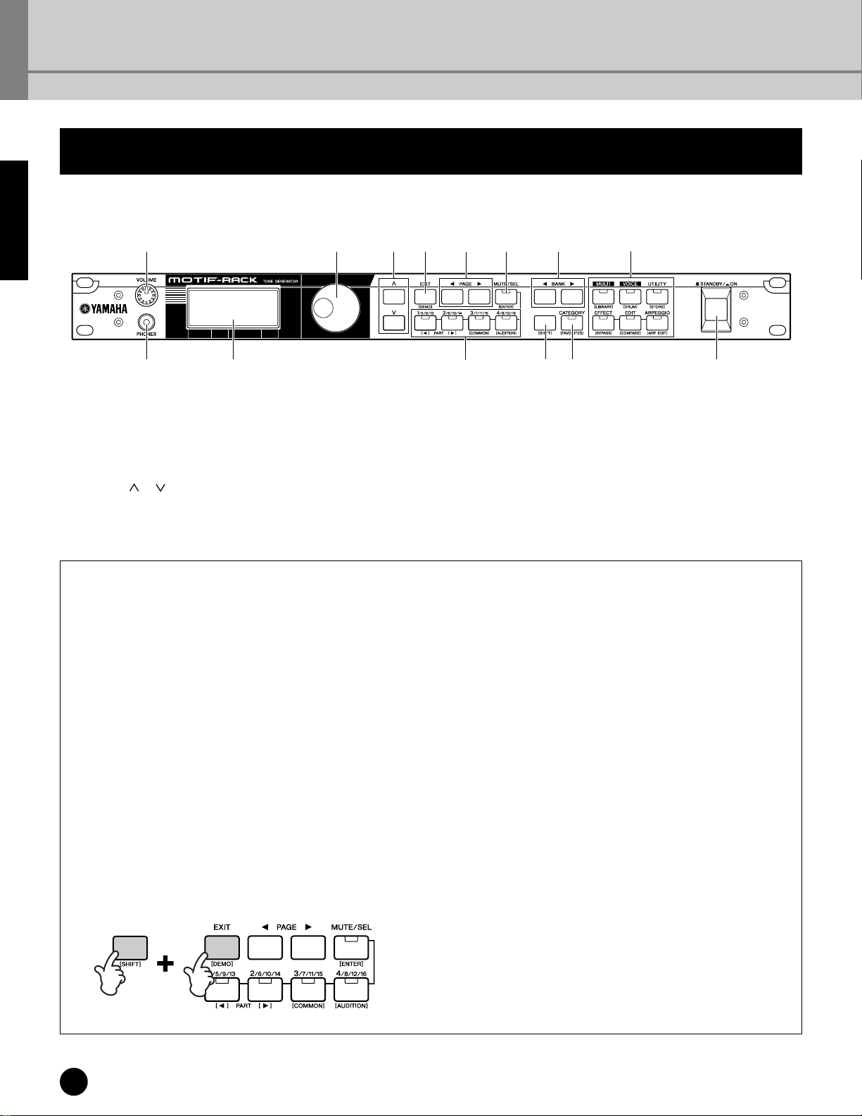
Front Panel
1468
23
1 [VOLUME] knob (page 14)
2 PHONES jack (page 15)
3 LCD (Liquid Crystal Display) (page 32)
4 Data dial (page 33)
5
Cursor [ ] [ ] buttons (page 33)
6 [EXIT] button (page 32)
7 PAGE [EEEE] [FFFF] buttons (page 33)
Dual-function buttons
(Using the [SHIFT] button)
Some of the panel buttons have two functions. The
primary one is printed above the button and the
secondary one is printed below. Use the [SHIFT]
button (!) to select the secondary function — by
simultaneously holding down [SHIFT] and pressing
the relevant button.
For example, the [EXIT] button (6) has two
functions: EXIT and DEMO. To select the Exit
function, press the [EXIT] button. To select the
Demo function, hold down the [SHIFT] button and
press the [EXIT] button.
Throughout this manual, the secondary name of a
button is used when describing the secondary
function. For example, a description of the Demo
function may contain the sentence, “Hold down the
[SHIFT] button and press the [DEMO] button.”
7)5
9
8 [MUTE/SEL] button (page 38)
9 PART/ELEMENT buttons (pages 38, 44)
) BANK [EEEE] [FFFF] buttons (page 35)
! [SHIFT] button (see below)
@ [CATEGORY] button (page 36)
# MODE buttons (page 31)
$ [STANDBY/ON] switch (page 14)
!@ $
#
Dual-function buttons
6 [EXIT] button → [DEMO] button
8 [MUTE/SEL] button → [ENTER] button
9 [1/5/9/13] button → PART[EE
[2/6/10/14] button → PART[FF
[3/7/11/15] button → [COMMON] button
[4/8/12/16] button → [AUDITION] button
@ [CATEGORY] button → [FAVORITES] button
# [MULTI] button → [LIBRARY] button
[VOICE] button → [DRUM] button
[UTILITY] button → [STORE] button
[EFFECT] button → [BYPASS] button
[EDIT] button → [COMPARE] button
[ARPEGGIO] button → [ARP EDIT] button
EE
FF
] button
] button
12
The Controls & Connectors
Page 13
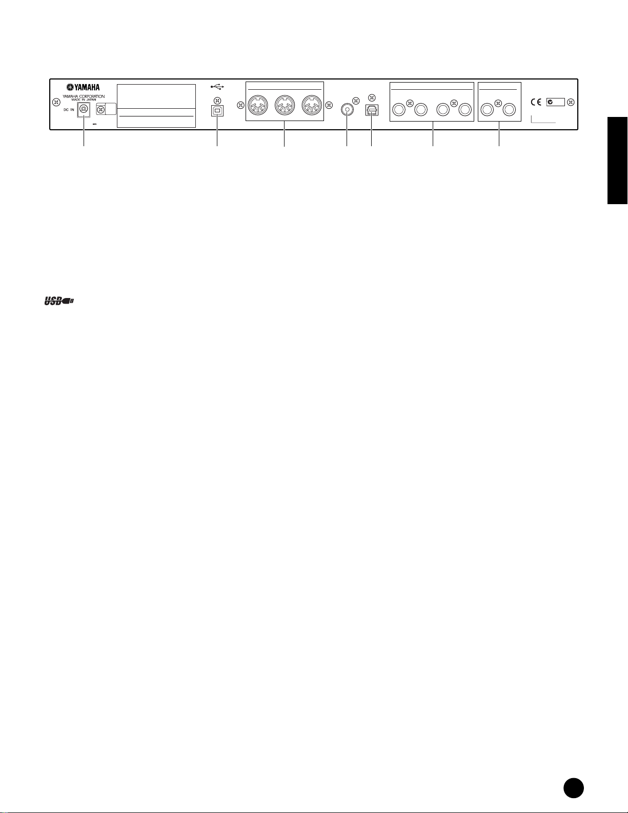
Rear Panel
MODEL MOTIF-RACK
AC POWER ADAPTOR:
YAMAHA PA-300 16V
THIS DEVICE COMPLIES WITH PART 15 OF
THE FCC RULES. OPERATION IS SUBJECT
TO THE FOLLOWING TWO CONDITIONS:
(1) THIS DEVICE MAY NOT CAUSE HARMFUL
INTERFERENCE, AND (2) THIS DEVICE MUST
ACCEPT ANY INTERFERENCE RECEIVED,
INCLUDING INTERFERENCE THAT MAY CAUSE
UNDESIRED OPERATION.
THIS CLASS B DIGITAL APPARATUS COMPLIES
WITH CANADIAN ICES-003.
CET APPAREIL NUMÉRIQUE DE LA CLASSE B
EST CONFORME À LA NORME NMB-003
DU CANADA.
USB
MIDI
THRU OUT IN
DIGITAL
OUTPUT
OPTICAL
OUTPUT
ASSIGNABLE OUTPUT OUTPUT
4321
R
L/MONO
N89
SER NO.
&(*%^ º¡
% DC IN terminal (page 14)
^ USB terminal (page 16)
& MIDI IN/OUT/THRU terminals (page 16)
* DIGITAL OUTPUT jack (page 15)
( OPTICAL OUTPUT jack (page 15)
º ASSIGNABLE OUTPUT 1-4 jacks (page 15)
¡ OUTPUT L/MONO & R jacks (page 15)
USB is an abbreviation for Universal Serial Bus. It is a serial interface for connecting a computer with peripheral
devices, and allows “hot swapping” (connecting peripheral devices while the power to the computer is on).
Before Using
The Controls & Connectors
13
Page 14
Setting Up
Before Using
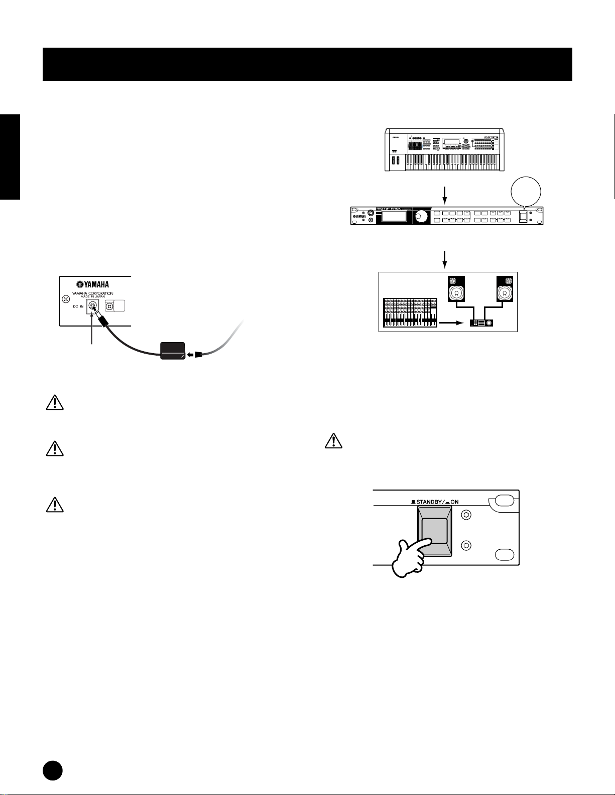
Power Supply
Make sure that the MOTIF-RACK’s [STANDBY/ON]
switch is set to the STANDBY (off) position.
1 Connect one end of the AC cable to the PA-300.
2 Connect the PA-300’s DC plug to the MOTIF-
RACK’s DC IN terminal on the instrument’s rear
panel.
3 Connect the other end (normal AC plug) to the
nearest electrical outlet.
Rear Panel
MODEL MOTIF-RACK
AC POWER ADAPTOR:
YAMAHA PA-300 16V
PA-300
DC IN
2
1
Use only the AC power adaptor supplied with the
MOTIF-RACK or an equivalent recommended by
Yamaha. The use of an inappropriate replacement can
pose a fire and shock hazard!
Make sure your MOTIF-RACK is rated for the AC
voltage supplied in the area in which it is to be used (as
listed on the rear panel). Connecting the unit to the
wrong AC supply can cause serious damage to the
internal circuitry and may even pose a shock hazard!
Even when the switch is in the “STANDBY” position,
electricity is still flowing to the instrument at the
minimum level. When not using the MOTIF-RACK for
an extended period of time, be sure to unplug the AC
power adaptor from the wall AC outlet.
To electrical outlet
AC cable
device in the reverse order (audio devices first, then
MIDI).
MUSIC
SYNTHESIZER
PRODUCTION
Sequencer
Sampling
Integrated
Real-timeExternalControl
Surface
Modular
SynthesisPlug-in
System
MIDI master (transmitting device)
POWER
ON!!
MOTIF-RACK as MIDI slave
(MIDI receiving device)
123456789101112 13 14 15 16 L R
Audio equipment
(mixer first, then amplifier)
Turning on the MOTIFRACK
Before you switch your MOTIF-RACK on or off, turn
down the volume of any connected audio equipment.
1 Press the [STANDBY/ON] switch.
Power-on Procedure
Once you’ve made all the necessary connections (page
15) between your MOTIF-RACK and any other
devices, make sure that all volume settings are turned
down all the way to zero, then turn on the every device
in your setup in the order of MIDI masters (senders),
MIDI slaves (receivers), then audio equipment
(mixers, amplifiers, speakers, etc.). This ensures
smooth signal flow from the first device to the last (first
MIDI, then audio).
n When powering down the setup, first turn down the
volume for each audio device, then switch off each
14
Setting Up
After a while, the default display appears (as set in
the Utility parameter, Power On Mode display).
n If the LCD is difficult to read, you may need to adjust
the display contrast. To do this, simultaneously hold
down the [UTILITY] button and turn the data dial.
2 Raise the sound system volume to a reasonable
level.
3 Turn the MOTIF-RACK’s [VOLUME] knob
clockwise to set an appropriate volume level.
Page 15
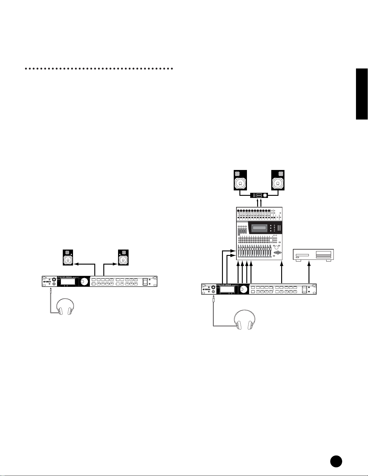
Connections
Connecting to External Audio
Equipment
Since the MOTIF-RACK has no built-in speakers,
you’ll need an external audio system or a set of stereo
headphones to properly monitor it. Alternatively, you
could use a pair of headphones.
There are several methods of connecting to external
audio equipment, as described in the following
illustrations. The following illustrations show various
connection examples; use the one most similar to your
intended setup.
n To use the MOTIF-RACK, you’ll also need a proper
MIDI controller (such as a keyboard) or other MIDI
device (such as a sequencer or computer). For MIDI
connections, see the next section.
Connecting to a mixer
There are extra audio outputs in addition to the
OUTPUT (L/MONO and R) jacks. Connect these
outputs to a mixer for separately controlling the
outputs of up to six Parts in the Multi mode (page 31).
You can specify the output routing of each Part in the
Multi Edit Mode (Ref. #96).
If your mixer or other audio device features digital
input connections, we recommend using the DIGITAL
OUTPUT (coaxial) terminal or the OPTICAL
OUTPUT terminal. These ensure completely noisefree, distortion-free sound output.
n Using the DIGITAL OUTPUT/OPTICAL OUTPUT, you
can record the performance of the MOTIF-RACK to
external media (e.g. MD recorder) with exceptionally
high-quality sound.
n The sounds from the DIGITAL OUTPUT and OPTICAL
OUTPUT jacks are the same as those from the OUTPUT
L/MONO and R jacks.
Speaker
Before Using
Connecting Stereo Powered Speakers
A pair of powered speakers can accurately produce the
instrument’s rich sounds with their own pan and effect
settings.
Connect your powered speakers to the OUTPUT L/
MONO and R jacks on the rear panel.
Powered speaker (Left)
OUTPUT L /MONO
PHONES
Headphones
MOTIF-RACK
n When using just one powered speaker, connect it to the
OUTPUT L/MONO jack on the rear panel.
Powered speaker (Right)
INPUTINPUT
OUTPUT R
OUTPUT L /
MONO
PHONES
Mixer
L
OUTPUT L
R
MOTIF-RACK
Headphones
Amplifier
R
ASSIGNABLE
OUTPUT
R
External recorder
DIGITAL
OUTPUT
OPTICAL
OUTPUT
n Connecting a pair of headphones does not affect audio
output from the OUTPUT (L/MONO and R) jacks. You
can monitor the same sounds via headphones and at the
OUTPUT jacks. However, you cannot monitor the
sounds from the ASSIGNABLE OUTPUT 1-4 with
headphones.
n System effects and Master equalizer settings are not
applied to the sounds output from the ASSIGNABLE
OUTPUT 1-4 jacks.
n The Volume Knob does not affect the signals at the
DIGITAL OUTPUT, OPTICAL OUTPUT and
ASSIGNABLE OUTPUT.
Setting Up
15
Page 16
Connecting External MIDI
Equipment
Playback using an external MIDI
sequencer
Before Using
Using a standard MIDI cable (available separately),
you can use an external MIDI device (such as a
keyboard or sequencer) to control the sounds on the
MOTIF-RACK. Below are several different MIDI
connection examples; use the one most similar to your
intended setup.
n The “MIDI IN/OUT” parameter (UTILITY MIDI
display) should be set to “MIDI.” Otherwise, MIDI data
will not be transmitted from the MOTIF-RACK’s MIDI
OUT connector.
Controlling from an External MIDI
Keyboard
External MIDI keyboard or synthesizer
MUSIC SYNTHESIZER
Modular Synthesis Plug-in System
MIDI OUT
MIDI IN
MOTIF-RACK
External MIDI sequencer
MIDI OUT
MIDI IN
MIDI IN
MIDI OUT
MOTIF-RACK
n Set “Echo Back” (or “MIDI Echo,” etc.) on your
sequencer on or off as necessary, depending on your
MIDI setup. For details, refer to the owner’s manual of
your particular sequencer.
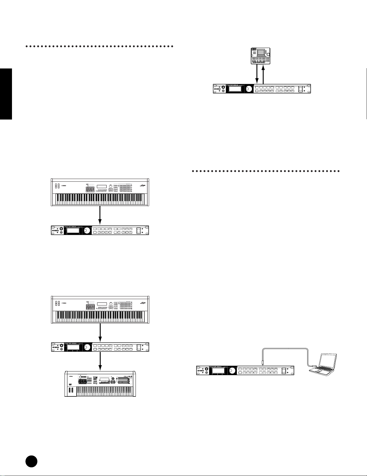
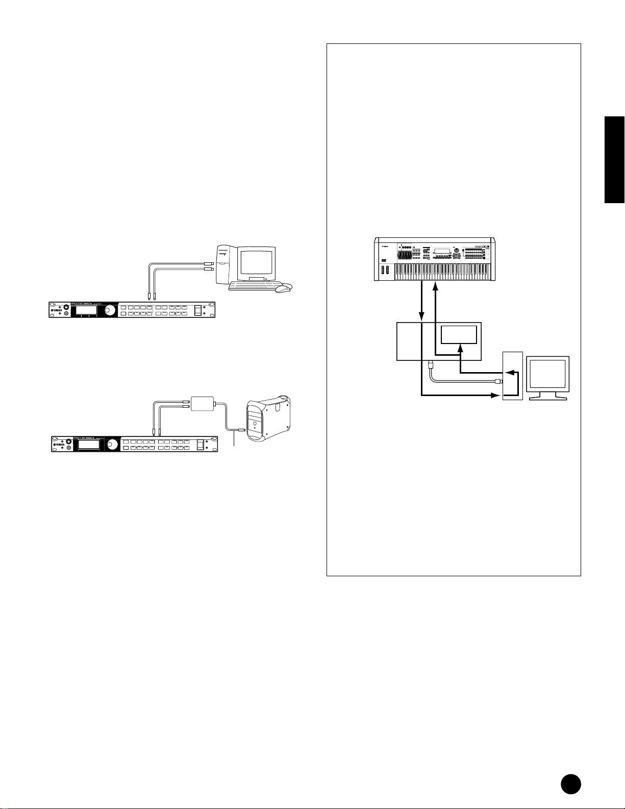
Connecting to a Personal
Computer
By connecting a computer, you can transfer data
between the MOTIF-RACK and the computer via
MIDI, and use the computer to control, edit and
organize data on the MOTIF-RACK. For example, you
can use the included Voice Editor program to edit the
MOTIF-RACK’s voices.
There are two ways to connect your MOTIF-RACK to
a computer:
1. USB connection
2. MIDI connection
Controlling another MIDI device via
MIDI THRU
External MIDI synthesizer 1
MUSIC SYNTHESIZER
Modular Synthesis Plug-in System
MIDI OUT
MIDI IN
MIDI THRU
MIDI IN
External MIDI synthesizer 2
In the above setup, Synthesizer 1 plays Synthesizer 2
(via MIDI THRU).
MOTIF-RACK
MUSIC
SYNTHESIZER
PRODUCTION
Sequencer
Sampling
Integrated
Real-timeExternalControl
Surface
Modular
SynthesisPlug-in
System
Depending on your particular computer, the
connections may differ. (See below.)
1. USB connection
When using the USB terminal on the MOTIF-RACK,
set the “MIDI IN/OUT” parameter to “USB” in the
Utility mode.
USB cable
USB terminal
MOTIF-RACK
n When connecting the MOTIF-RACK to a computer with
a USB cable, make sure that the USB cable is properly
connected before turning on the power.
Be careful not to turn off the power of the MOTIFRACK if an application using the USB/MIDI connection
is currently running.
n Once connected via USB, the MOTIF-RACK begins
communication after a short time.
Computer with a
USB interface
16
Setting Up
Page 17
n When connecting the MOTIF-RACK and your computer
via USB, make sure to connect them directly without
routing through a USB hub.
n The USB connection can only be used for transfer of
MIDI data. No audio data can be transferred via USB.
2. Using a MIDI interface
When using MIDI terminals on the MOTIF-RACK, set
the “MIDI IN/OUT” parameter to “MIDI” in the
Utility mode.
Using with a computer and an external
MIDI keyboard
If you are using a computer with sequencing
software to control the MOTIF-RACK, you can
connect an external MIDI keyboard to record note
and other data (and even play back recorded data).
Use the setting suggestions below as a guideline;
specific instructions may differ depending on your
computer and the software used.
Before Using
n Make sure to set the “MIDI IN/OUT” parameter
(Ref. #160) to “USB.”
Using the computer’s MIDI interface
MIDI OUT
MIDI OUT
MIDI IN
Computer with MIDI
Interface
MIDI cable
MIDI IN
MOTIF-RACK
Using an external MIDI interface
MIDI Interface
MIDI OUT
MIDI IN
MIDI IN MIDI OUT
MOTIF-RACK
n Make sure to use the appropriate MIDI interface for
your computer.
n If you are using a computer that has a USB interface,
make sure to connect the computer and the MOTIFRACK by USB. (The data transfer rate is faster than
MIDI and you’ll have access to multiple MIDI ports.)
Computer
Serial port
(modem or printer
port) or USB port
External MIDI keyboard or synthesizer
MUSIC
SYNTHESIZER
PRODUCTION
Sequencer
Sampling
Integrated
Real-timeExternalControl
Surface
Modular
SynthesisPlug-in
System
MIDI OUT MIDI IN
MIDI OUTMIDI IN
Computer with
Application
Software
MOTIF-RACK
Tone
Generator
USB cable
Echo Back On
n When using the USB terminal (“MIDI IN/OUT” is
set to “USB”), the MOTIF-RACK also receives and
relays any data received via the MIDI IN terminal.
*MIDI “Echo” is a function on sequencers that
takes any data received via the MIDI IN and
“echoes” it (or sends it as is) through the MIDI
OUT. In some software, this function is also called
“MIDI Thru.”
n Refer to the owner’s manual of your particular
software for specific instructions.
Setting Up
17
Page 18
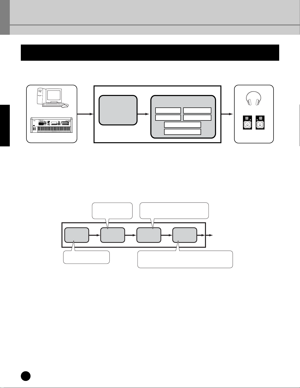
Basics Section
Overview of the MOTIF-RACK
This section gives you an overview of the MOTIF-RACK’s features. The following diagram shows the various
component sections or “blocks” of the MOTIF-RACK.
Basics Section
Computer with
Application Software
External MIDI
keyboard
MIDI IN
Tone Generator Effect
AWM2
Plug-in Board
Reverb
Chorus
Master Equalizer
Part Equalizer
Insertion 1
Insertion 2
Headphone
External
Speaker
MIDI T ransmitting device
OutputMOTIF-RACK
Tone Generator
This block plays back sounds according to MIDI data received from the external keyboard or sequencer. The
following example illustrates the path taken by the signal from an Element in the Voice Mode (page 25).
Changes the tonal quality of each
Element output from the PITCH
section.
FILTER
Controls the output level (amplitude) of each Element
output from the FILTER section. The signals are then sent
at this level to the Effect block.
AMP
(Amplitude)
To Effect Units
Tone Generator
OSC
(Oscillator)
Outputs the waveform
of each Element.
Controls the pitch of
each Element output
from the OSC section.
PITCH
18
Overview of the MOTIF-RACK
Page 19
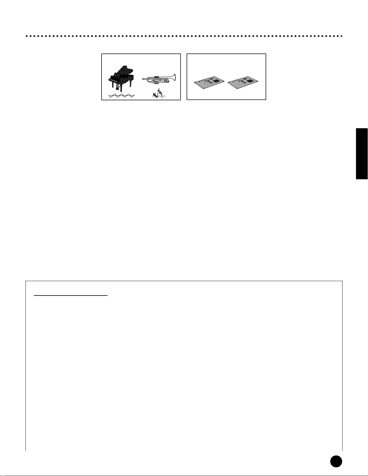
Internal AWM2 Tone Generator and optional Plug-in board
The tone generator block in the MOTIF-RACK consists of the built-in AWM2 and optional Plug-in units.
Internal AWM2 Tone Generator
Plug-in boards (optional)
● AWM2 (Advanced Wave Memory 2) & Waveform
AWM2 (Advanced Wave Memory 2) is a synthesis system based on sampled waves (sound material), and is used in
many Yamaha synthesizers. For extra realism, each AWM2 Voice uses multiple samples of a real instrument’s
waveform. Furthermore, a wide variety of envelope generator, filter, modulation, and other parameters can be
applied to the basic waveform.
n AWM2 is not just limited to general musical instruments (Normal Voices). It can also be used for setting up percussive
instruments (Drum Voices). For details on Normal and Drum Voices, see page 25.
● Plug-in Boards
Plug-in Boards give you an enormous amount of additional sonic flexibility and power. When installed, they work
seamlessly and transparently within the system of the MOTIF-RACK – meaning that you can use their sounds and
functions just as if they were built right into the MOTIF-RACK at the factory.
Up to two Plug-in Boards can be installed to the MOTIF-RACK (see box below for available boards). These boards
are not simply a source of more Voices; they are also tone generators in their own right and extend the system-level
specifications such as maximum polyphony. In addition, they allow you to use synthesis systems besides AWM2.
You can play Plug-in Voices just like ordinary internal Voices and use them as Parts in a Multi (page
The MOTIF-RACK is compatible with the Modular Synthesis Plug-in System. Two types of Modular Synthesis Plugin System-compatible Plug-in Boards can be installed to the MOTIF-RACK: Single Part and Multi-Part Plug-in Board.
Using these, you can build your own system based on the sounds you want or need.
n The Effect Plug-in Board cannot be used with the MOTIF-RACK.
30).
Basics Section
lug-in board line-up
P
Single Part Plug-in Boards
• Analog Physical Modeling Plug-in Board (PLG150-AN)
Using Analog Physical Modeling (AN) synthesis, the very latest digital technology is used to accurately reproduce the sound of
analog synthesizers. With this board installed, you have real-time control over the playback of vintage synthesizer sounds as well
as the very latest sounds heard in today’s dance and pop music.
• Piano Plug-in Board (PLG150-PF)
A massive amount of waveform memory is dedicated to the reproduction of piano sounds. This board offers 136 stereo sounds,
including a number of acoustic and electric pianos, and up to 64-note polyphony. You can even install two of these boards to
double the polyphony to 128 notes.
• Advanced DX/TX Plug-in Board (PLG150-DX)
The sounds of the DX7 are available on this Plug-in Board. Unlike with PCM-based tone generators, this board uses the powerful
FM Synthesis system— the same as found on DX-series synthesizers— for extraordinarily versatile and dynamic sound shaping
potential. Sounds are compatible with those of the DX7, and the board can even receive DX7 data via MIDI bulk dump.
• Virtual Acoustic Plug-in Board (PLG150-VL)
With Virtual Acoustic (VA) synthesis, the sounds of real instruments are modeled (simulated) in real time, giving a degree of
realism that cannot be achieved using conventional PCM-based synthesis techniques. When playing these sounds using an
optional MIDI Wind Controller (WX5), you can even capture some of the physical feel of woodwind instruments.
• Drums Plug-in Board/Percussion Plug-in Board (PLG150-DR/PLG150-PC)
Incorporates the highly-acclaimed AWM2 engine dedicated to the reproduction of drum/percussion sounds. This board also has
its own dedicated effects processing. This means that you can apply Reverb and insertion effect to the voice, letting you use all of
the effects on the “mother” device for the other Parts.
Overview of the MOTIF-RACK
19
Page 20
Basics Section
Maximum Polyphony
The maximum sonic polyphony is 128 for AWM2, plus the polyphony of the Plug-in Board(s) (if installed). The
actual note polyphony will vary depending on the type of tone generator unit used, the number of Elements in the
Voice, and the note polyphony of the Plug-in Board.
In the case of AWM2 Voices, the polyphony figure of 128 is divided by the number of Elements in the Voice.
Multi-Part Plug-in Board
Multi-Part Plug-in Boards let you expand the voice polyphony of the MOTIF-RACK by providing an additional sixteen
independent instrument parts. This is an ideal way to play back song data from a sequencer (from the Multi-Part board), yet have
full polyphony left over on the MOTIF-RACK for your live performance parts.
• XG Plug-in Board (PLG100-XG)
This Plug-in Board is a 16-part XG sound generator. You can play back XG/GM song files using the rich variety of sounds and
effects on this board.
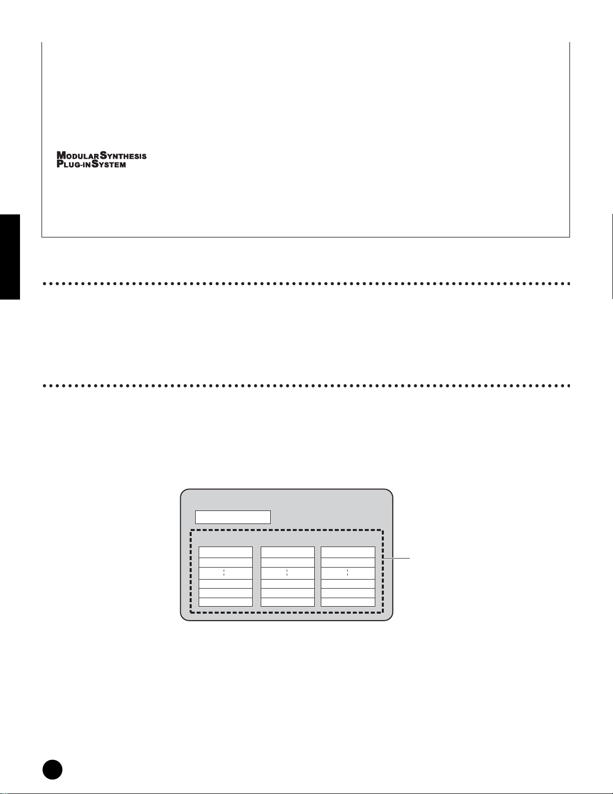
About MODULAR SYNTHESIS PLUG-IN SYSTEM
The Yamaha Modular Synthesis Plug-in System offers powerful expansion and upgrade capabilities for Modular Synthesis-Plug-incompatible synthesizers, tone generators and sound cards. This enables you to easily and effectively take advantage of the latest
and most sophisticated synthesizer and effects technology, allowing you to keep pace with the rapid and multi-faceted advances in
modern music production.
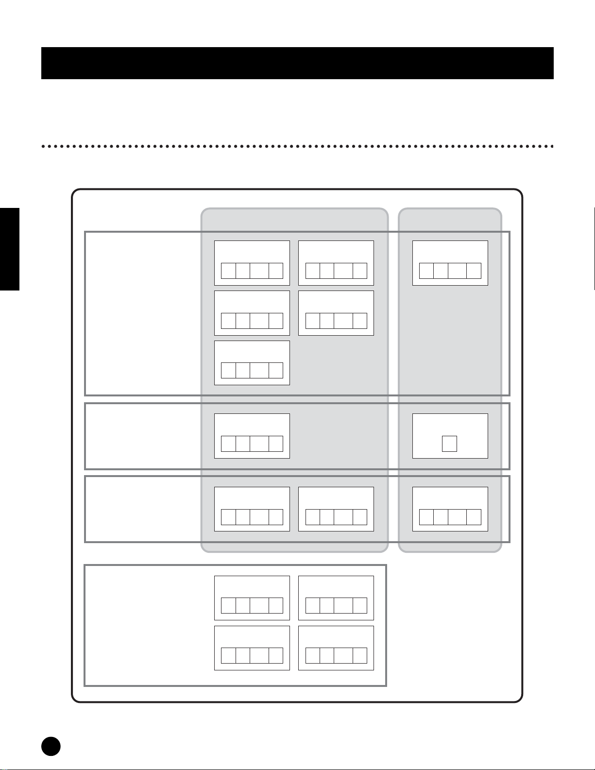
Part structure of the Tone Generator block
The MOTIF-RACK plays its sounds (with the Tone Generator block) in response to MIDI data, received from the
external keyboard or sequencer.
MIDI data is assigned to one of sixteen channels, and the MOTIF-RACK is capable of simultaneously playing sixteen
separate parts, via the sixteen MIDI channels. However, we can overcome the sixteen-channel limit by using separate
MIDI “ports,” each supporting sixteen channels.
The multiple sound sources of the MOTIF-RACK (internal tone generator and Plug-in Boards) take advantage of the
three MIDI ports included on the instrument.
Tone Generator block
Part for Voice mode
Port 1 Port 2 Port 3
part 1
part 2
part 14
part 15
part 16
As shown in the above illustration, up to 48 parts can be used in the modes in the Multi mode. However, the number
of parts that are actually used a maximum of 33 (as shown in the example on the next page).
part 17
part 18
part 30
part 31
part 32
part 33
part 34
part 46
part 47
part 48
Part for Multi mode
n See page 31 for details about the modes.
n The USB connection supports up to eight separate MIDI ports. The tone generator of the MOTIF-RACK supports three separate
MIDI ports, as shown above. However, you can control an external tone generator with a fourth port by using the Thru Port
function to relay MIDI data from one of the ports to the MIDI OUT terminal.
n A single MIDI cable connection cannot handle multiple port data.
20
Overview of the MOTIF-RACK
Page 21
Part Structure – Voice/Multi Modes
● Voice mode
Tone Generator block (Internal / Plug-in)
External MIDI keyboard
External sequencer
Part for Voice mode
Port 1 Port 2 Port 3
part 1
part 2
part 3
part 4
part 5
part 16
part 17
part 18
part 30
part 31
part 32
Parts 1-48 are not used.
part 33
part 34
Output
part 46
part 47
part 48
n In the Voice mode, the MIDI port number is 1.
n The Multi-Part Plug-in Board cannot be used in the Voice mode. Only Single-Part Plug-in Boards can be used.
● Multi mode
Tone Generator block (example)
When the Multi-Part Plug-in Board and one Single Part Plug-in Board
have been installed:
External sequencer
External MIDI keyboard
MIDI cables by themselves cannot
handle data from multiple ports. If a MIDI
cable is used to transmit data from an
external sequencer, only the Port 1 parts
are used. To take advantage of the
multiple ports of the MOTIF-RACK, use a
USB cable.
Port 1 Port 2
Part 1
Part 2
Part 3
Part 4
Part 15
Part 16
(Multi-Part Plug-in
Board)
Part 17
Part 18
Part 30
Part 31
Part 32
Port 3
(Single Part Plug-in
Board)
Part 33
Part 34
Part 47
Part 48
PLG1 part
Part 34-48 are
not used.
Basics Section
n The Multi-Part Plug-in Board (PLG100-XG) can be installed only to PLG2.
n The MIDI port number for Parts 1-16 is 1.
n You can assign the PLG1/PLG2 part to any of the available ports with the Port Number parameter (Ref. #176).
Overview of the MOTIF-RACK
21
Page 22

Effects
The effects of the MOTIF-RACK employ sophisticated DSP (digital signal processing) technology, letting you
enhance or dramatically change the sound. In the final stages of programming, you can set the effects parameters to
further change the sound’s character.
The MOTIF-RACK’s effect processing features the following four effect units: System effects, Insertion effects, Part
equalizer, and Master equalizer.
● System Effects (Reverb, Chorus)
System Effects are applied to the overall sound, whether it be a voice, or an entire multi setup.
With System effects, the sound of each part is sent to the effect according to the effect Send Level for each part. The
processed sound (referred to as “wet”) is sent back to the mixer, according to the Return Level, and output — after
being mixed with the unprocessed “dry” sound. This arrangement lets you prepare an optimum balance of the effect
Basics Section
sound and the original sound of the parts.
Reverb
The Reverb effects add a warm ambience to the sound, simulating the complex reflections of actual performance
spaces, such as a concert hall or a small club.
A total of 20 different Reverb types are available.
Chorus
The Chorus effects provide a wide variety of sound transformations and enhancements. A total of 44 different
Chorus types are available.
● Insertion Effects (1, 2)
Insertion effects can be applied individually to each part.
Insertion effects are mainly used to directly process a single part. The depth of the effect is adjusted by setting the
dry/wet balance. Since an Insertion effect can only be applied to one particular part, it should be used for sounds you
want to drastically change. You can also set the balance so that only the effect sound is heard, by setting Wet to 100%.
The MOTIF-RACK features two Insertion effect systems (Insertion 1 and 2) — each with a total of 107 internal
effect types.
● Part Equalizer
The Part Equalizer is used to correct the tonal balance of Voices assigned to each Part by raising or lowering three
frequency bands.
In other words, this lets you fine-tune the sound of each Part to make it “sit better” in the overall mix. For example,
you can emphasize an important Part in the mix by making it brighter or boosting the mid range, while making other
sounds around it softer. Or if a bass Part and piano Part are competing in the mix, you can make the two sound better
by cutting the low range of the piano.
● Master Equalizer
Usually an equalizer is used to correct the sound output from amps or speakers to match the special character of the
room. The sound is divided into several frequency bands, then by raising or lowering the level for each band, the
correction is made. The MOTIF-RACK has a high-quality five-band digital equalizer that lets you adjust the overall
sound according to the type of music you play — classical music being more refined and soft, pop music more crisp,
and rock music more dynamic. This allows you to emphasize the special characteristics of the music and make your
performance more enjoyable.
22
Overview of the MOTIF-RACK
Page 23
Effect connection
● In the Voice mode:
Three different Insertion connection types are available, as shown below.
Tone Generator
block
Element 1
Insertion
Send Level Return LevelReverb
Effects
Element 2
Element 3
Element 4
This determines which Insertion
system, 1 or 2, is applied to each
Element (or to each key when the
Drum Voice is selected).
The Insertion effect can also be
bypassed.
1
2
1 to 2 2 to 1
1
2
n The parallel connection type is not available for Plug-in voices.
System Effects
Chorus
You can select the Insertion connection
from the three types shown below.
1
2
parallel
1
2
Master Equalizer
Output
Basics Section
● In the Multi mode:
The diagram below indicates the connection when the Multi-Part Plug-in Board (PLG100-XG) is installed to PLG2.
Tone Generator
block
Part 1
Part 2
Part
Equalizer
Part 16
PLG part
(Multi-Part
Plug-in board)
Part 17-32
The insertion
effect is applied to
up to four parts.
Insertion
Effects
Send Level
Dry Level
* Insertion Effect settings differ depending on the particular Voice assigned to the selected part.
System
Effects
Reverb
Chorus
Return Level
Master
Equalizer
Output
n The Part Equalizer in not applied to the Parts of Plug-in board.
n The Insertion effects and System effect are not applied to the Parts of the Multi-part Plug-in board.
Overview of the MOTIF-RACK
23
Page 24
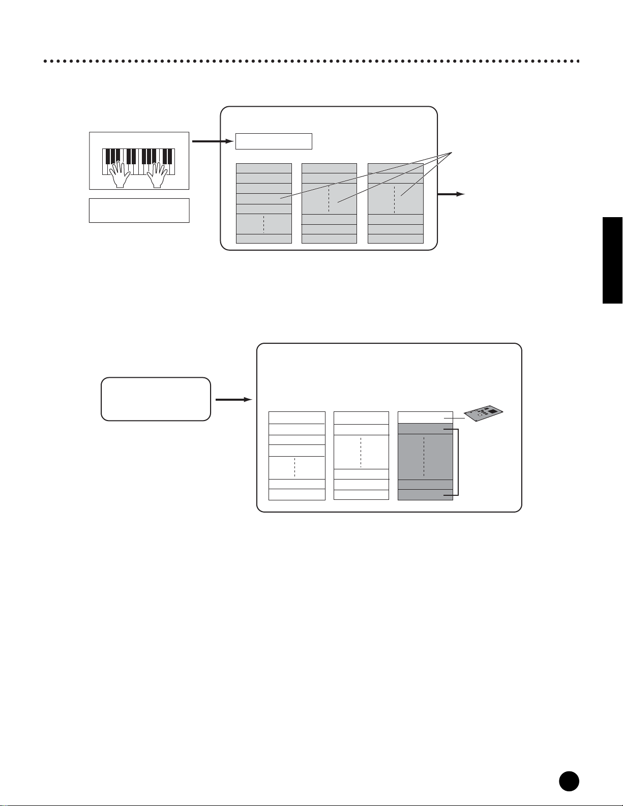
Voice Structure
Memory Structure
A Voice is a single instrument sound, created by using the Elements and setting various parameters. In the Voice Play
mode (page 35), you can select and play any of these Voices.
Basics Section
Voices & Multis
Voices
Normal V oice Drum V oice
Preset V oice
Normal Voices: 640
Drum Voices: 48
GM V oice
Normal Voices: 128
Drum Voice: 1
User V oice
Normal Voices: 256
Drum Voices: 32
Preset 1
(128 Voices)
12 128
......
Preset 2
(128 Voices)
12 128
......
Preset 3
(128 Voices)
12 128
......
GM Preset
(128 Voices)
12 128
......
User 1
(128 Voices)
12 128
......
Preset 4
(128 Voices)
12 128
......
Preset 5
(128 Voices)
12 128
......
User 2
(128 Voices)
12 128
......
Preset Drum
(48 Voices)
12 48
......
GM Drum
(1 Voice)
1
User Drum
(32 Voices)
12 32
......
24
Voices & Multis
Plug-in V oice
* When the PLG150-VL is installed, there are three Preset Banks and 192 preset voices.
PLG1 Preset
(64 Voices)
12 64
......
PLG1 User
(64 Voices)
12 64
......
PLG2 Preset
(64 Voices)
12 64
......
PLG2 User
(64 Voices)
12 64
......
Page 25
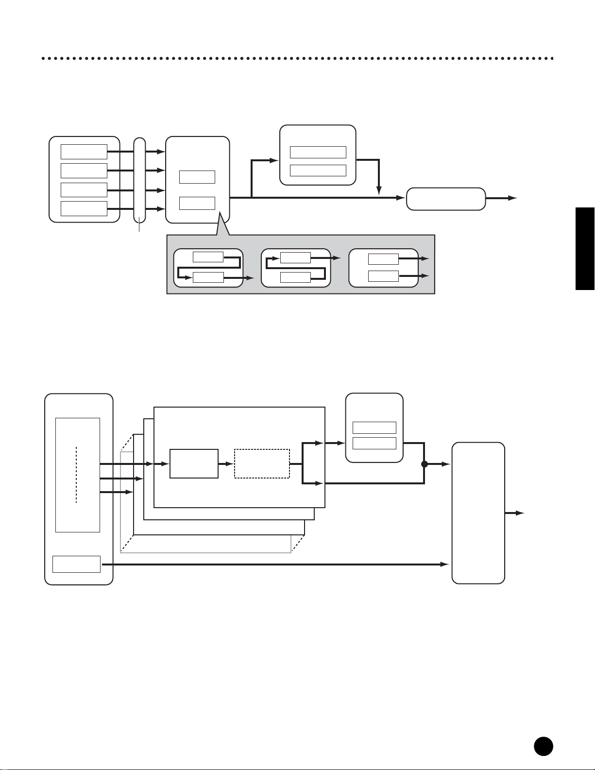
Normal Voices & Drum Voices
Internally, there are two Voice Types: Normal Voices and Drum Voices. Normal Voices are mainly pitched musical
instrument-type sounds that can be played over the range of the keyboard. Drum voices are mainly percussion/drum
sounds that are assigned to individual notes on the keyboard. A collection of assigned percussion/drum waves or
Normal Voices is known as a Drum Kit.
Normal V oice
Voice
Element 1~4
Individual drum
sounds (different
for each key)
Key 1 Key 2 Key 3 Key 4 Key 5 Key 73
Drum V oice
GM voices
GM is a worldwide standard for Voice organization and MIDI functions of synthesizers and tone generators. It was
designed primarily to ensure that any song data created with a specific GM device would sound virtually the same on
any other GM device — no matter the manufacturer or the model. The GM Voice bank on the MOTIF-RACK is
designed to appropriately play back GM song data. However, keep in mind that the sound may not be exactly the
same as played by the original tone generator.
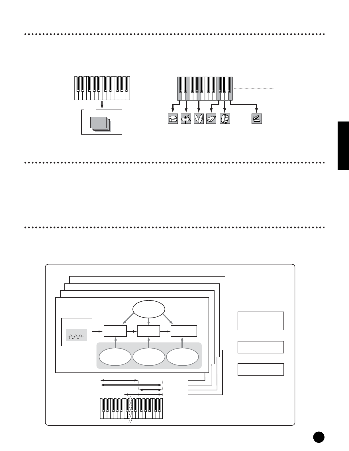
Normal Voices & Elements
Each Normal Voice can consist of up to four Elements. Each Element itself is a high-quality waveform or instrument
sound. Since you can combine up to four Elements together in a voice, highly expressive and richly textured sounds
are possible. You can also split different instrument sounds across the external keyboard to be playable separately
with your left and right hands – without having to specially set up a Multi program.
Basics Section
One Voice (up to four elements)
Element 4
Element 3
Element 2
Element 1
Oscillator
Wave (AWM2)
C-2 G8
PITCH FILTER AMP
EG
PEG
(Pitch Envelope
Generator)
LFO
(Low Frequency
Oscillator)
FEG
(Filter Envelope
Generator)
AEG
(Amplitude Envelope
Generator)
Element 1
Element 2
Element 3
Element 4
+
+
+
Common Edit
parameters
Arpeggio
Effects
Voices & Multis
25
Page 26
Voice Edit Structure
One voice consists of Oscillator, Pitch, Filter, Amplitude, LFO and various parameters as shown on page 25.
You can create the basic voice character by setting these five parameters.
● Oscillator
This unit outputs the wave of each Element. You can
set the note range for Element (the range of notes on
the keyboard over which the Element will sound) as
well as the velocity response (the range of note
velocities within which the Element will sound).
For example, you could set one Element to sound in an
upper range of the keyboard, and another Element to
Basics Section
sound in a lower range. Thus, even within the same
Voice, you can have two different sounds for different
areas of the keyboard or you can make the two Element
ranges overlap so that their sounds are layered over a
set range. Furthermore, you can set each Element to
respond to different velocity ranges so that one
Element sounds for lower note velocities, whereas
another Element sounds for higher note velocities.
● PITCH
This unit controls the pitch of each Element output
from OSC.
You can detune separate Elements, apply Pitch Scaling
and so on. Also, by setting the PEG (Pitch Envelope
Generator), you can control how the pitch changes
over time.
Velocity
Element 1
C-2 G8
Element 3
Element 2
Element 4
Note Range
Pitch
Hold Level
0
Hold
Time
Attack
Time
Attack
Level
Decay1
Level
Decay1
Time
Decay2
(Sustain) Level
Decay2
Time
Key off
Release
Time
Release
Level
Time
● Filter
This unit modifies the tone of each Element output
from Pitch by cutting the output of a specific frequency
portion of the sound.
You can also set the Filter Envelope Generator (FEG),
to control how the filter works over time — letting you
set up dynamic changes in tone.
Cutoff Frequency and Resonance
Filters work by allowing the portion of the signal lower
than a given frequency to pass, and cutting the portion
of the signal above that frequency. This frequency is
referred to as the cutoff frequency. You can produce a
relatively bright or darker sound by setting the cutoff.
Resonance is a parameter that boosts the level of the
signal in the area of the cutoff frequency. By
emphasizing the overtones in this area, this can
produce a distinctive “peaky” tone, making the sound
brighter and harder.
Level
Cutoff frequency
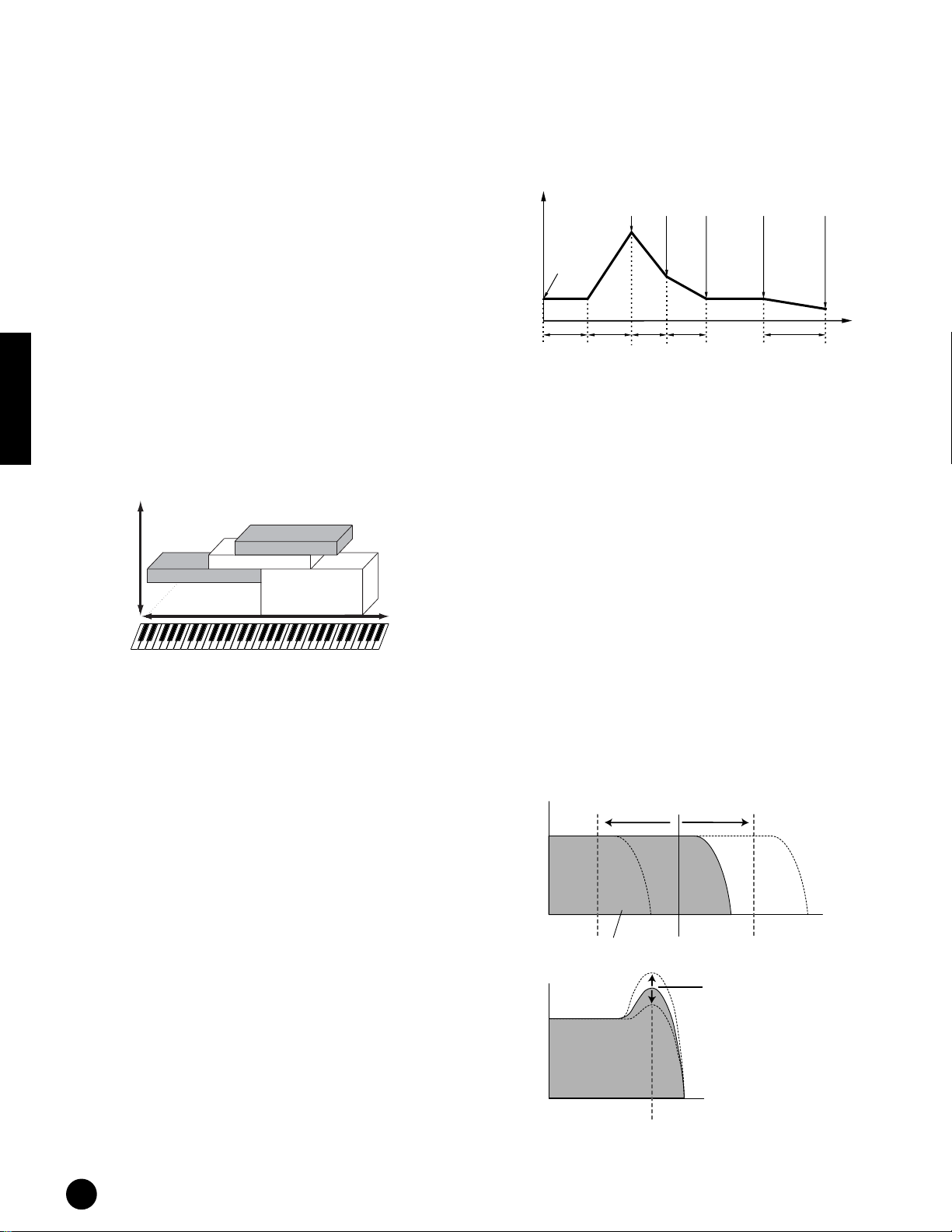
PEG (Pitch Envelope Generator)
Using the PEG, you can control the transition in pitch
from the moment a Note On message is received to the
point at which the sound stops. As illustrated below,
the Pitch Envelope consists of five Time (transition
speed) parameters and five Level (pitch) parameters.
This is useful for creating automatic changes in pitch.
Furthermore, different PEG parameters can be set for
each Element.
26
Voices & Multis
Frequency (pitch)
These resonance are
“passed” by the filter.
Level
Resonance
Frequency (pitch)
Cutoff frequency
n About the filter types of the MOTIF-RACK, see page 27.
Page 27
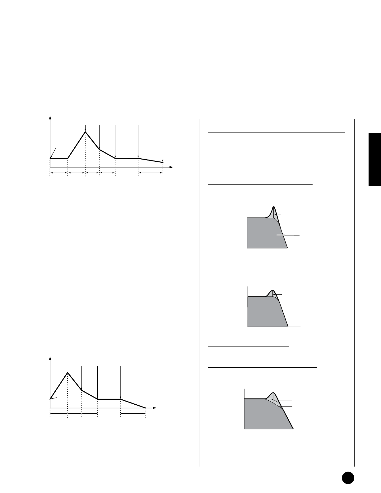
FEG (Filter Envelope Generator)
Using the FEG, you can control the transition in tone
from the moment a Note On message is received to the
point at which the sound stops. As illustrated below,
the Filter Envelope consists of five Time (transition
speed) parameters and five Level parameters (for the
amount of filtering). When you press a note on the
keyboard, the cutoff frequency will change according to
these envelope settings. This is useful for creating
automatic wah effects, for example. Furthermore,
different FEG parameters can be set for each Element.
● LFO (Low Frequency Oscillator)
As its name suggests, the LFO creates waveforms of a
low frequency.
These waveforms can be used to vary the pitch, filter or
amplitude of each Element to create effects such as
vibrato, wah and tremolo. These waveforms can be
used to vary the pitch, filter or amplitude of each
Element to create effects such as vibrato, wah and
tremolo. LFO can be set independently for each
Element; it can also be set globally for all Elements.
Release
Time
Release
Level
Time
Cutoff
Frequency
Hold Level
0
Hold
Time
Attack
Time
Attack
Level
Decay1
Level
Decay1
Time
Decay2
(Sustain) Level
Decay2
Time
Key off
● Amplitude
This unit controls the output level (amplitude) of each
Element output from Filter.
The signals are then sent at this level to the Effect
block. Also, by setting the AEG (Amplitude Envelope
Generator), you can control how the volume changes
over time.
AEG (Amplitude Envelope Generator)
Using the AEG, you can control the transition in
volume from the moment a Note On message is
received to the point at which the sound stops. As
illustrated below, the Amplitude Envelope consists of
four Time (transition speed) parameters and three
Level parameters (for the amount of filtering). When
you press a note on the keyboard, the volume will
change according to these envelope settings.
Furthermore, different AEG parameters can be set for
each Element.
Level
Decay1
Level
Decay2
(Sustain) Level
Key off
About the Filter Type of the MOTIF-RACK
Low Pass Filter
This only passes signals below the Cutoff frequency. You
can then use the Resonance parameter to add further
character to the sound. The MOTIF-RACK features six
Low Pass filter types as follows.
Basics Section
LPF24D (Low Pass Filter 24dB/oct Digital)
A 4-pole (-24db/oct) dynamic LPF with a strong
Resonance.
Resonance
These frequencies
are “passed” by
the filter.
LPF24A (Low Pass Filter 24dB/oct Analog)
A 4-pole (-24db/oct) dynamic LPF with a character similar
to those found on analog synthesizers.
Resonance
LPF18 (Low Pass Filter18dB/oct)
A 3-pole (-18db/oct) dynamic LPF.
LPF18s (Low Pass Filter 18dB/oct Staggered)
A 3-pole (-18db/oct) dynamic LPF, but with a shallower
frequency curve.
Initial
Level
0
Attack
Decay1
Time
Time
Decay2
Time
Release
Time
Time
Resonance
LPF18
LPF18s
Voices & Multis
27
Page 28
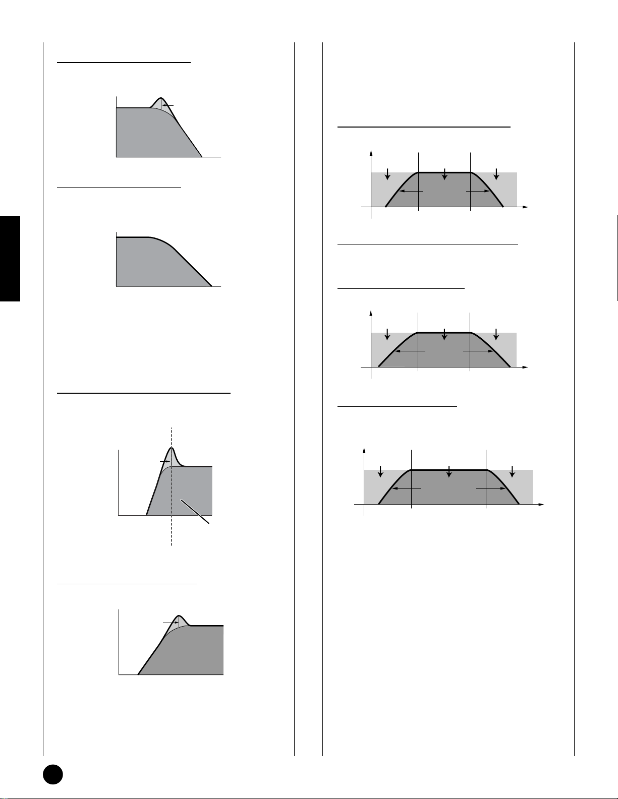
LPF12 (Lo
w Pass Filter12dB/oct)
A 2-pole (-12db/oct) dynamic LPF, designed to be used in
combination with an HPF (High Pass Filter).
Resonance
Band Pass Filter
This only passes a band of signals around the Cutoff
frequency. The width of this band can be varied. The
MOTIF-RACK features four Band Pass filter types as
follows.
BPF12D (Band P
Level
Cutoff range Range passed Cutoff range
ass Filter 12dB/oct Digital)
Basics Section
LPF6 (Low Pass Filter 6dB/oct)
A 1-pole (-6db/oct) dynamic LPF with no resonance,
designed to be used in combination with an HPF (High
Pass Filter).
High Pass Filter
This only passes signals above the Cutoff frequency. You
can then use the Resonance parameter to add further
character to the sound. The MOTIF-RACK features two
High Pass filter types as follows.
HPF24D (High Pass Filter 24dB/oct Digital)
A 4-pole (-24db/oct) dynamic HPF with a strong
Resonance.
Resonance
–12db/oct
Frequency
BPF12s (Band Pass Filter 12dB/oct Staggered)
Basically same as BPF12D, but with a shallower frequency
curve.
BPF6 (Band Pass Filter 6dB/oct)
Level
Cutoff range Range passed
–6db/oct
Cutoff range
Frequency
BPFw (Band Pass Filter Wide)
Also the combination of a –12dB/oct HPF and LPF, but
allows a wider frequency band.
Level
Cutoff range Range passed
Cutoff range
Cutoff Frequency
HPF12 (High Pass Filter 12dB/oct)
A 2-pole (-12db/oct) dynamic HPF.
Resonance
28
Voices & Multis
width can be
increased
Frequency
These frequencies are
“passed” by the filter.
Page 29

Band Elimination Filter
This attenuates a band of signals around the Cutoff
frequency, but passes everything else.
The MOTIF-RACK features two Band Elimination Filter
types as follows.
BEF12 (Band Elimination Filter 12dB/oct)
BEF6 (Band Elimination Filter 6dB/oct)
Dual BEF
A combination of two sets of -6dB/oct BEF in series.
Level
Level
Range passed
Cutoff range
Center frequency
Range passed
Frequency
Other filter types
MOTIF-RACK also has the filters made combining two
filters. If “thru” is selected, the filters are bypassed.
Dual LPF
A combination of two sets of -12dB/oct LPF in parallel.
Level
Distance
The cutoff frequency can be set
directly on the display.
Frequency
Distance
The cutoff frequency can be set
directly on the display.
Frequency
LPF12 (Low Pass Filter 12dB/oct) + HPF12 (High Pass
Filter)
A combination of a LPF and HPF.
Level
Distance
The cutoff frequency can be set
directly on the display.
Frequency
LPF12 (Low Pass Filter 12dB/oct) + BPF6 (Band Pass
Filter)
A combination of a LPF and BPF.
Level
Basics Section
Dual HPF
A combination of two sets of -12dB/oct HPF in parallel.
Level
Distance
The cutoff frequency can be set
directly on the display.
Frequency
Dual BPF
A combination of two sets of -6dB/oct BPF in parallel.
Level
Distance
The cutoff frequency can be set
directly on the display.
Frequency
Frequency
HPF12 (High Pass Filter 12dB/oct) + BPF6 (Band Pass
Filter)
A combination of a HPF and BPF.
Level
Frequency
thru
The filters are bypassed and the entire signal is unaffected.
n Filter parameters are also available in Part editing in
Multi mode.
Voices & Multis
29
Page 30

Multi Structure
A Multi consists of up to 16 Parts, each of which can play a Normal Voice or Drum Voice Part. By assigning different
Voices and MIDI channels to each part, and by using a sequencer or computer for song data playback, you can have a
complete ensemble of 16 independent instrument sounds. You can also play Multis from the external keyboard. This
allows you to set up layers of different Voices, or special key splits in which your right and left hands can play
separate Voices.
One Multi (Up to 16 parts and Plug-in Part 1, 2)
Plug-in Part 2 (PLG2)
Plug-in Part 1 (PLG1)
Part 16
Basics Section
Plug-in part (PLG 1, PLG 2)
PLG 1 Part and PLG 2 Part are the parts to which the Plug-in board voices are assigned when a Single part Plug-in
Board is installed. For details, refer to page 21.
n For details on assigning a Voice to a Part, see page 44.
Voice
Part 1
Voice
Plug-in Board V
● Plug-in Voices and Board Voices
The Voices built into and used directly from the Plug-in Board are referred to as “Board Voices,” while the Plug-in Board Voices
that are processed with the parameters (Plug-in voice parameters) of the MOTIF-RACK are referred to as “Plug-in Voices.” If the
Plug-in Board has been correctly installed, the Voice data appropriate for the installed board is set up automatically as preset Plugin Voices and you can select the Plug-in bank as well as the built-in Voice bank. You can also edit the Plug-in Board Voices and store
them as Plug-in User Voices.
oices
Part Edit Parameter
+
Part Edit Parameter
+
+
Different Voice for each part
Common Edit
parameters
Plug-in V oice
Board V oice
+
To select a desired Plug-in Voice in the Voice mode, first select the appropriate bank, PLG1 or PLG2. These banks contain the
preset Plug-in Voices, Plug-in User Voices, and Board Voices. When you select the Board Voices, the Plug-in voice parameters are
reset. For details on selecting Board Voices, see page 35.
In the Multi mode, you can select the Board Voice bank as well as preset Plug-in Voice banks.
n The Board voices can be edited by a computer connected to the MOTIF-RACK, using special editing software included with the
Plug-in board. The edited voices can be saved in MOTIF-RACK’s internal memory with the Plug-in Save function (page 56).
30
Voices & Multis
Plug-in voice
parameters
Page 31

Basic Operations
In this section, you’ll learn about the structure of the modes of the MOTIF-RACK, its panel display indications and
its fundamental operations.
Modes
[VOICE] button
VOICE Mode
MULTI Mode
Other modes
[MULTI] button
[EFFECT] button
[EDIT] button
Mode Selecting a mode Display Indications (P.32)
Play Play a Voice [VOICE] (A)
Edit Edit a Voice [VOICE]→[EDIT] (B)
Effect Edit Edit the Voice Effect settings [VOICE]→[EFFECT] (G)
Arpeggio Edit Edit the Arpeggio settings [VOICE]→[SHIFT]+[ARPEGGIO] (H)
Play Play a Multi [MULTI] (C)
Multi Library Use the Multi Library [SHIFT]+[MULTI] (D)
Mixing Edit Edit a Multi (simple mixing) [MULTI](→[MULTI]) (E)
Edit Edit a Multi (detailed mixing) [MULTI]→[EDIT] (F)
Effect Edit Edit the Multi Effect settings [MULTI]→[EFFECT] (G)
Arpeggio Edit Edit the Arpeggio settings [MULTI]→[SHIFT]+[ARPEGGIO] (H)
Utility Global settings for the entire system [UTILITY] (I)
Effect Bypass Set the Effect Bypass [SHIFT]+[EFFECT] (J)
[UTILITY] button
[ARPEGGIO] button
Basics Section
n Parameters are divided into two basic groups: (1) functions that are related to each Voice and Multi, and (2) functions that affect
all Voices and Multis. The former are set in the Edit mode and latter in the Utility mode.
n The parameter settings in the Voice/ Multi mode can be saved to User memory with the store function (page 57).
Utility/Effect Bypass mode settings will be saved when exiting from the mode. (Never attempt to turn off the power while an
“Executing...” or “Please keep power on” message is shown.) If you turn off the power without exiting from Utility/Effect Bypass
mode, your custom settings will be lost.
Basic Operations
31
Page 32

Mode selection and Display indications
Basics Section
(A) V oice Play
1 2
3
4
5
(C) Multi Play
1
[EDIT]
[EXIT]
(B) V oice Edit
Common Edit ([SHIFT]+[COMMON])
Drum Key Edit ([SHIFT]+PART[EEEE][FFFF])
1 7 8 &
4
)
@
Element Edit ([1/5/9/13]-[4/8/12/16])
1 7 8 &
4
)
@
(D) Multi Library
6
!
!
*
3
4
%
(E) Mixing Edit
1 7! 8 &
)
@
[MULTI]
*
[SHIFT]+[LIBRARY]
[EXIT]
[EXIT]
4
[EDIT]
[EXIT]
[EDIT]
#
[EDIT]
(F) Multi Edit
Common Edit ([SHIFT]+[COMMON])
1 7 8 &
4
)
@
Part Edit ([1/5/9/13]-[4/8/12/16])
1 7 8
4
)
@
!
!
*
32
Basic Operations
Page 33

(G) Effect Edit
Effect Connect
4
)
1 Mode
&
2 Voice: NORMAL/DRUM
3 Bank/Number
!
4 Category/Name
[EFFECT]
[EXIT]
[SHIFT]
+
[ARP EDIT]
[EXIT]
[UTILITY]
[EXIT]
$
Effect Edit
4
^
@
(H) Arpeggio Edit
4
)
@
(I) Utility
1 8
)
@
[EFFECT]
9 &
[SHIFT] + [ARP EDIT][EFFECT]
%
5 Functions assigned to the ASSIGN A/B/1/2
6 Library bank: Perf/Multi (selected via BANK
[EEEE][FFFF] buttons)
7 Edit type: COMMON/ELEM1-4/KEY/PART01-16
8 Edit-display name
(selected via PAGE [EEEE][FFFF] buttons)
9 Effect name being edited
(selected via PAGE [EEEE][FFFF] buttons)
) Parameter name
Basics Section
(selected via cursor [ ][ ] buttons)
! Settings (changing values using the data dial)
&
@ Parameter list
(scroll using the cursor [ ][ ] buttons)
!
# Library list (scroll using the cursor [ ][ ] buttons)
$ Insertion Effect
% System Effect
^ Effect type
& Edit indicator (Indicates the current Voice/Multi
has been modified but not yet stored. In the
!
Compare condition, the indicator is shown; page
38.)
* Settings of each Element/Part parameter (select the
other Element/Part using [1/5/9/13] to [4/8/12/16]
buttons)
[SHIFT]
+
[BYPASS]
[EXIT]
(J) Effect Bypass
1
)
@
!
Basic Operations
33
Page 34

Quick Guide
Demo playback
The MOTIF-RACK features a variety of demo songs, showcasing its dynamic sound and sophisticated functions.
Here’s how to play them back.
n Make sure the MOTIF-RACK is ready for playback. Details are given in the section “Setting Up” on page 14.
Quick Guide
1 Press the [DEMO] button while holding [SHIFT] button. DEMO screen is shown in the display.
2 Select the song with the cursor [ ][ ] buttons.
3 Simultaneously hold down the [SHIFT] button and press the [ENTER] button to start playback of the DEMO
song.
2
1, 4
Demonstration songs
3
1, 3
4 To stop playback, press the [EXIT] button. Press it again to exit from the Demo mode.
34
Demo playback
Page 35

Playing the voices
Here, you’ll learn how to select and play Voices (instrument sounds) from the PRESET1-5, GM, USER 1-2 and PLG
1-2 memory groups (Banks).
n Details about Voices are given on page 24. For information on the Voice List, see the separate Data List.
n Up to 256 Normal Voices and 32 Drum Voices can be stored to User memory (page 57). The Voice settings can be changed in the
Voice Edit mode (page 37).
Let’s play some Voices. The example below assumes that you have connected an external MIDI keyboard to the
MOTIF-RACK.
Selecting a voice
Enter the Voice Play mode.
1
Press the [VOICE] button to enter the Voice Play mode.
The [VOICE] button LED will light in green, indicating
that the Voice Play Mode (Normal voice) is selected.
When you select a Drum voice, simultaneously hold
down the [SHIFT] button and press the [DRUM]
button. The LED will light in orange, indicating that
the Voice Play Mode (Drum voice) is selected.
Normal V oice
Drum V oice
Select a Voice Bank.
2
EE
Select a Voice Bank with the BANK [
Program number
Bank name
EE
][
FF
FF
] buttons.
There are eight different memory sections for the
Normal Voices (page 24): PRE 1-5, GM and USR 1-2.
For the Drum Voices, you can select from three
different memory sections: PRE, GM and USER.
If the Plug-in Board(s) are installed, PLG1 and PLG2
bank can be selected.
n You can also select a Board Voice Bank simultaneously
holding the [SHIFT] button and using the BANK
[EEEE][FFFF] buttons. The Bank Select MSB/LSB of the
Board voice is shown in the display. For details about the
Bank Select MSB/LSB, refer to the Owner’s manual that
came with your Plug-in Board.
Quick Guide
Select a program number with the
3
data dial.
n You can also select numbers with the cursor [ ][ ]
buttons.
Play the connected keyboard.
4
The selected Voice is played according as the received
MIDI message.
n There is an Audition function (page 36) that lets you
listen to and audition each Voice as you select it.
Playing the voices
35
Page 36

Using the Category Search function
The MOTIF-RACK features a powerful Category
search function that gives you quick access to the
sounds you want, irrespective of their bank locations.
Simply search a voice category, such as A. PIANO or
SYN LEAD, and you can browse through all related
voices one by one.
The LED will light, indicating that the Category search
function is on.
Quick Guide
Turn the Category Search function
on by pressing the [CATEGORY]
1
button.
jump around to other Categories — a great aid when
playing live.
Select the desired voice in the Voice list, and press
the [MUTE/SEL] button to checkmark the box next
to the voice name. (You can un-checkmark it by
pressing the [MUTE/SEL] button again.) Go on to
other Categories and continue registering your
favorites.
After you’ve checkmarked all the voice you want,
simultaneously hold the [SHIFT] button and press
the [FAVORITES] button to store them to the
Favorites Category. All the voices you’ve
checkmarked – and only those voices – will be
shown in the list. To exit from the Favorites
Category, simply press the [CATEGORY] button.
Press the [EXIT] button to return the Voice Play
mode.
When you exit from the Favorite Category
function, the parameter you changed in the
display is automatically stored. However, this
edited data is lost if you turn off the power
without properly exiting from the display.
Category names
Voice List
n To exit from the Category function, press the
[CATEGORY] button again, or press the [EXIT] button.
Select a Category with the BANK
2
[E][F] buttons.
Select a voice with the cursor [ ][ ]
3
buttons.
Favorite Categor
Use this convenient function to store all your
favorite, often-used voices in a single, easy-to-access
location — and call them up by simultaneously
holding the [SHIFT] button and pressing the
[FAVORITES] button. Select any voice you want,
from any desired category, and enter each to the
Favorites Category. In this way, you can go directly
to all the voices you use the most, without having to
y
udition function
A
You can hear Audition phrase played with the
selected voice by pressing the [AUDITION] button
while holding the [SHIFT] button.
Editing an Audition Phrase
The phrase type and pitch can be changed in the
Voice Edit mode. There is two parameters
concerning with the audition phrase in the
“General” display in the Voice Common Edit.
• A.PhraseNo. (Audition phrase number)
Selects the type of the Audition phrase.
• A.PhraseSft (Audition phrase shift)
Determines the pitch settings of the Audition
phrase in semitones.
n Audition Phrase data can be transmitted via MIDI
OUT (page 66, Ref. #71), and the transmit channel
can also be set (page 66, Ref. #72).
36
Playing the voices
Page 37

Voice Editing
The following procedure shows you the fundamentals
in creating and editing Voices. All Voice creation and
editing is carried out in the Voice Edit Mode.
Each Normal Voice consists of up to four Elements. To
edit the common parameters (common to all
Elements), enter the Common Edit Mode. To edit
parameters of individual Elements, enter the Element
Edit Mode.
n When you select a Drum Voice, enter the Key Edit Mode
and edit parameters of individual Keys of the Drum
Voice.
Of course, this is just one example; you are free to set
any parameters in any way you like. Details about each
parameter are given in the Reference section of this
manual (page 59).
n All parameter settings are stored along with the Voice
itself.
Set the Common Parameters.
3
Simultaneously hold down the [SHIFT] button and
press the [COMMON] button to call up the Common
Edit screen.
Indicates that the Common Edit Mode is selected.
The Common Edit Mode contains the following displays.
n The following displays are examples of a Normal voice. If
you select a Drum voice or Plug-in voice, the displays will
be different.
• General
For setting general parameters in Common Edit,
such as the Voice Name.
In the Voice Play Mode, select the
1
Voice you wish to edit.
Enter the Voice Play mode by pressing the [VOICE]
button. Select the Voice Number of the Voice you wish
to edit (page 35).
n When you’re creating a Voice by editing an existing one,
it helps to select a Voice with a sound that’s relatively
similar to the one you intend to create. In this way, you
can avoid having to make large changes and many
parameter edits — allowing you to create a Voice quickly
and easily. If you are creating a Voice from scratch, use
the convenient Initialize function (in the Utility Job
mode) to initialize a Voice in the internal user memory.
For details, see page 55.
Enter the Voice Edit Mode.
2
To enter the Voice Edit mode, press the [EDIT] button
while in the Voice Play mode. The LED will light,
indicating that the Voice Edit Mode is selected.
• Output
For setting the Voice output parameters such as the
output level (volume) and pan position.
• EG/FLT (Envelope Generator/Filter)
For setting the time variance of how the pitch, filter,
or level changes. You can also change some filter
parameters here.
• CtrlSet (Controller Set)
For determining how the MOTIF-RACK performs
when the MIDI control change data is received.
• LFO (Low Frequency Oscillator)
For setting the LFO parameters. The LFO uses a
low frequency waveform to vary the pitch/filter/
amplitude characteristics, and can be used to create
vibrato, wah, tremolo and other effects.
n For more information about the LFO, see page 27.
To change the display page, use the PAGE [EEEE][FFFF]
buttons. Select the desired parameter with the
cursor[ ][ ] buttons and change the settings by using
the data dial.
Quick Guide
Parameter name
Display name
Settings
Playing the voices
37
Page 38

C
ompare Function
When you’re editing a Voice or Multi, this feature
lets you quickly and easily hear the effect of the edits
you make — allowing you to switch between the
original, unedited Voice/Multi and the newly edited
settings.
1 While in the Edit mode, simultaneously hold
down the [SHIFT] button and press the
[COMPARE] button.
The EDIT LED will flash and the settings prior
to editing are temporarily called up for
comparing. (The indicator is shown at the top
right of the display in place of the indicator.)
2 Simultaneously hold down the [SHIFT] button
and press the [COMPARE] button to disable the
Compare function and restore your recently
edited settings.
n The Compare function is also available in the Multi
Edit mode.
When editing a Drum Voice, simultaneously hold down
the [SHIFT] button and use the PART [EEEE][FFFF]
buttons to select the desired key.
Selected key
n You can also select the desired key by using a connected
keyboard (via incoming Note On data). Simultaneously
hold down the [SHIFT] button and press the appropriate
key on the keyboard.
Quick Guide
Select the desired Element with the corresponding
Part/Element buttons [1/5/9/13]-[4/8/12/16] (Normal
Voice only). For example, press [1/5/9/13] button to
select Element 1.
n When the [MUTE/SEL] button’s status is set to
Set the Element Parameters.
4
“MUTE” (the LED lights), selecting elements is not
available.
Selected Element
Switching Elements (or Keys) On/Off
(Mute)
Each time you press the [MUTE/SEL] button, the
on/off status of the LED changes. When the
respective LEDs light, the corresponding Part/
Element buttons ([1/5/9/13] - [4/8/12/16]) are set to
the MUTE function. When the LED is turned off,
they have the SELECT function.
When the [MUTE/SEL] button’s lamp is lit, you can
mute any Element by pressing the corresponding
Part/Element button [1/5/9/13] to [4/8/12/16].
For example, you could mute all Elements other than
that which you are editing. In this way, you can hear
how the edited settings affect just that Element.
You can check which Element is muted by checking
the lamps of the Part/Element buttons. The LEDs of
the muted Element buttons are turned off and the
active Element buttons light.
When the [MUTE/SEL] button lamp is off, you can
select the desired Element for editing by pressing the
corresponding Part/Element button ([1/5/9/13] - [4/
8/12/16]).
If you select the muted Element, the LED of the
button flashes.
n You can also switch the on/off status of each Part
in the Multi mode.
38
Playing the voices
Page 39

The Element (Key) Edit Mode contains the following
displays.
n If you select a Drum voice or Plug-in voice, the display
will be different.
n For details about the following parameters, refer to the
Basics Section (page 26) and the Reference Section (page
59)
• OSC (Oscillator)
For setting the various parameters controlling the
waveforms on which the Voice is based. You can
select the Wave used for the Element, the volume
and note range of each Element and so on.
n When you select a Drum Voice, you can output each
key independently via the ASSIGNABLE OUTPUT
jacks by using the OutputSel parameter (No. 96, on
page 67).
• Pitch, PEG (Pitch Envelope Generator)
For setting the basic pitch parameters for each
Element. Also, by setting the PEG, you can control
how the pitch changes over time.
EE
To change the display page, use the PAGE [
EE
][
FF
FF
buttons. Select the desired parameter with the cursor
[][] buttons and change the settings by using the
data dial.
Display name
Parameter name
Set the Effect Parameters.
5
Element 1 Element 3
Element 2 Element 4
Settings
]
• Filter, FEG (Filter Envelope Generator)
For changing the tonal characteristics of each
Element, by adjusting overtones included in the
waveform of the Element. You can also set the FEG
for time variance of how the filter works— in other
words, dynamically change the tone and timbre of
the sound over time.
• AMP (Amplitude), AEG
(Amplitude Envelope Generator)
For setting the volume of each Element after the
OSC (Oscillator), PITCH and FILTER parameters
have been applied, as well as the final overall
volume of the signal sent to the outputs. Also, by
setting the AEG, you can control how the volume
changes over time.
• Native (Native Part Parameters:
Plug-in Voice only)
For editing the Native Part Parameters. Refer to the
Owner’s manual of the Plug-in Board.
• LFO (Low Frequency Oscillator)
For setting the LFO parameters for the Normal
Voices.
For an application example showing how to use the
effect, see page 41.
Storing edited Voice.
6
Up to 256 new/edited Normal Voices and 32 new/
edited Drum Voices can be stored to internal user
memory.
Voice
Store
Normal Voice
USER1 (USR1)
1-128
Normal Voice
USER2 (USR2)
1-128
Drum Voice
USER DRUM
1-32
For details about storing Voices, see page 57.
When storing a Voice, any existing data at the storage
location will be lost. You should always back up your
important data to computer.
Quick Guide
• EQ (Part Equalizer)
For adjusting the tonal qualities of each Element.
Playing the voices
39
Page 40

C
ontrol Sets
The MOTIF-RACK has no physical controller of its
own. However, you can use the controllers (keys,
wheels, sliders, switches, etc.) on an connected
instrument to affect the sound of the MOTIF-RACK.
For example, the Modulation wheel could be
assigned to control filter resonance, while aftertouch
could be used to apply vibrato. This provides
enormous flexibility in controlling parameters and
setting up the controllers to suit the kind of sound
being played.
These controller assignments are known as Control
Sets. As the following illustration shows, you can
assign up to six different Control Sets per Voice.
2 Set the “Set1Dest” parameter to “ELM-Pan
(Element Pan).”
n For details on the available Dest parameter
settings, refer to the Control List in the separate
Data List booklet.
3 Set the depth of control by changing the
“Set1Depth” parameter setting.
n If you are editing a Normal Voice, set the on/off
status of the Control Set for each Element with the
“Set1ElmSw” parameter.
Repeat Steps 1 and 3 above to assign the remaining
Control Sets 2 through 6.
Quick Guide
Control set 6
Control set 5
Control set 4
Control set 3
Control set 2
Control set 1
Source
Controller (PB, MW, etc.)
Destination
Control Parameters
Depth
Depth of control
Element
Element 2Element 3Element
1
on/off
on/off
on/off
4
on/off
Within each Control Set, the controller is known as
the Source and the parameter controlled by the
Source is known as the Destination (Dest).
● Controlling a Voice
The Voice Common Edit parameters includes a
Control Set (CtrlSet) display for setting the Control
set parameters.
Source Dest. Depth
Set 1 MW ELM-Pan +15
Set 2 PB FLT-Rez +10
::::
● Controlling the Common parameters for the
MOTIF-RACK
There are two controllers available for controlling
parameters common to all Voices and Multis: ASA
(Assignable A) and ASB (Assignable B).
The relevant Control Set parameters can be set from
the Controller Assign (CtrlAsn) display in the
Utility mode.
You can select the Destination of the ASA/ASB
controllers with the “ASA Dest” and “ASB Dest”
parameters.
● Assigning Control Change number
Each controller has a pre-assigned Control Change
number. When the MOTIF-RACK receives Control
Change messages, the corresponding parameter (as
determined in the Control Set) is changed, and the
degree of change is determined by the set depth.
These assignments can be set in the following
display (mode).
For example, in the instructions below, we’ll control
panning with an external Modulation wheel.
1 Set the “Set1Source” parameter in the CtrlSet
display to “MW (Modulation wheel)”.
n The following Source parameters are available:
AS1/AS2 (Assignable 1/2), PB (Pitch Bend wheel),
MW (Modulation wheel), AT (Aftertouch), FC1/
FC2 (Foot controller 1/2), FS (Foot switch), BC
(Breath controller)
40
Playing the voices
•To control a Voice: “Voice” display (Utility)
•To control a Multi: “CtrlAsn” display (Multi
Common Edit)
•To control the common parameter for the
MOTIF-RACK: “CtrlAsn” display (Utility)
n The Control Change number assignment made to
one Voice affects all Voices. For Multis, each Multi
can have its own independent Control Change
number assignment.
Page 41

Using Voice Effects
In the final stages of programming, you can set the
effects parameters to further change the sound’s
character. In the Voice Mode, you can set up and store
the effects with each Voice.
n For details of the effect structure, see page 22.
Here we’ll show an example of editing effect settings in
the Voice Edit Mode.
Select the Voice you wish to edit
1
(page 35).
Enter the Effect Edit Mode.
2
Set the Insertion Effect Parameters.
3
The following parameters are used to edit the Insertion
Effect.
Select the desired parameter with the cursor [ ][ ]
buttons and change the setting by using the data dial.
• EL1InsEFOut - EL4InsEFOut
(Insertion Effect Out)
Determines which effect (1 or 2) is used to process each
individual element. The “thru” setting lets you bypass
the Insertion effects for the specific element/key.
n When editing the Drum voice, first select the key
with the “Ins EFOutKey” parameter, then determine
which effect (1 or 2) is used for the selected key.
n You can also select the desired key by simultaneously
holding down the [SHIFT] button and pressing the
appropriate key on the connected keyboard.
Press the [EFFECT] button to enter the Effect Edit
mode.
The LED lights and the following display is shown.
Normal V oice
Drum V oice
Plug-in V oice
n If this display is not shown, press the [EFFECT] button
again.
• Ins1Ctgry, Ins2Ctgry (Insertion 1/2 Category)
Determine the effect type category for Insertion 1
and 2.
• Ins1Type, Ins2Type (Insertion
Determine the effect type for Insertion 1 and 2.
• InsEFCnct (Insertion Effect Connect Type)
Determines the effect routing for Insertion 1 and 2
(page 23).
1/2
Type)
Set the System Effect (Reverb,
4
Chorus) Parameters.
Set the System Effect (Reverb, Chorus) Parameters
from the same display as in step 3 above.
Quick Guide
Playing the voices
41
Page 42

The following parameters are used to edit the System
Effect. Select the desired parameter with the cursor
[][] buttons and change the setting by using the
data dial.
n For information on the Effect Parameters, refer to the
separate Data List.
• ReverbType (Reverb Type)
RevSend (Reverb Send)
ReverbRtn (Reverb Return)
ReverbPan (Reverb Pan)
Determines the Reverb Effect settings, such as type,
send level, return level, panning.
• ChoCtgry (Chorus Category)
ChoType (Chorus Type)
ChoSend (Chorus Send)
ChoRtn (Chorus Return)
ChoPan (Chorus Pan)
Determines the Chorus Effect settings, such as type,
send level, return level, panning.
Storing edited Voice.
6
If you wish to save the new settings, store the settings
with the other Voice parameters as a single Voice
before you leave the selected Voice. For details about
storing Voices, see page 57.
If you call up another Voice or another mode without
saving, the edited settings may be lost.
Quick Guide
• ChoToRev (Chorus to Reverb)
Press the [EFFECT] button again to call up the
following display.
Use the PAGE [
type that you want to edit.
Select the desired parameter with the cursor [ ][ ]
buttons and change the setting by using the data dial.
n For information on the Effect Parameters, refer to the
n If “thru” is selected for the effect type, none of the effect
Determines the send level from Chorus to Reverb.
Edit the detailed Effect parameters.
5
Effect Type (Ins1, Ins2, Rev, Cho)
EE
FF
EE
][
FF
] buttons to select the Effect
separate Data List.
parameters can be edited.
42
Playing the voices
Page 43

Using the Multi Mode
The Multi Mode lets you set up the MOTIF-RACK as a multitimbral tone generator for use with computer-based
music software or external sequencers. If each track in a song file uses a different MIDI channel, you independently
assign each of the Parts in a Multi to those MIDI channels. In this way, you can play back the song data on a
sequencer with each track playing a different Voice.
Playing in the Multi mode
In the Multi Play mode, you can select and play any of
the Multis.
n For more details about Multis, see page 30.
n Up to 128 Multis can be stored in the USER (internal)
memory. These Multi settings are available in the Mixing
Edit mode (page 44) and the Multi Edit mode (page 45).
Enter the Multi Play mode.
1
Press the [MULTI] button. The LED lights, indicating
that the Multi Play mode is selected. The following
display appears.
Select a Multi number using the
2
data dial.
n You can also select numbers with the cursor [ ][ ]
buttons.
n Up to 128 Multis can be stored to User (internal)
memory. Internal memory contains the factory default
Multis.
n The category Search function (page 36) can also be used
to select a Multi in the same way as in the Voice play
mode. Multi Categories can be edited in the Multi Edit
mode (page 45).
Play the selected Multi.
3
When a Note On message is received, the
corresponding part is played.
For example, when you play a connected external
keyboard, the part whose Receive Channel is same as
the keyboard’s Transmit Channel is played. If the MIDI
receive channel parameter is the same for any Parts,
those Parts will play in unison.
Quick Guide
Multi Play Mode
External keyboard External sequencer
Tone Generator
Multi
Part
12345 678 16
Voic e
Playing a Multi
Song playback
Using the Multi Mode
43
Page 44

Simple Mixer functions (Mixing Edit Mode)
The Mixing Edit mode lets you easily edit some basic
parameters with a graphic mixer-like layout that allows
you to check each part’s setting. This mode is useful for
changing parameters for each part even while song data
is being played back from a connected sequencer.
Simple mixing functions and basic parameters are
provided in the mode, such as selecting Voices, changing
effect settings and so on. If you want to edit a Multi in
greater detail, see the Multi Edit mode (page 45).
Press the [MULTI] button in the Multi Play mode. The
[MULTI] button LED changed from green to red,
indicating that the Mixing Edit mode is selected.
Quick Guide
Enter the Mixing Edit mode.
1
Select the desired display.
3
EE
Select the desired display by using the PAGE [
EE
][
FF
FF
buttons, then edit the parameters in each display.
The Mixing Edit mode has three edit displays: Voice,
Output, and Effect.
•Voice
From this display you can select a Voice for each
Part. Select a Voice Bank with the “BankMSB/
BankLSB” parameter and select the desired Voice
with the “VoiceNo.” parameter.
n By selecting the BankMSB/BankLSB parameter with the
cursor [ ][ ] buttons and using the data dial, you can
call up the Voice Banks listed below.
Normal Voice Drum Voice Plug-in Voice
Pr1-5: Preset
Banks
GM: GM Bank GD: GM Drum Bank
Us1-2: User Voice
Banks
*For details about Plug-in Board Voices, refer to page 30.
PD: Preset Drum Bank
UD: User Drum Bank
Pp (Pp1-3): Plug-in
Preset Bank(s)
Pu1-3: Plug-in User
Banks
PB: Plug-in Board
Voice Bank*
]
Select the desired Part.
2
Select the desired Part with the Part/Element buttons
([1/5/9/13] – [4/8/12/16]).
Repeatedly pressing one of the buttons alternates
among the Part numbers. For example, pressing the [1/
5/9/13] button repeatedly calls up Parts 1, 5, 9 and 13
in order.
You can also step through the Parts in order by
simultaneously holding down the [SHIFT] button and
EE
FF
EE
][
FF
using the PART [
] buttons.
•Output
From this display you can set the Pan and Volume
for each Part.
Select “Pan” or “Volume” with the cursor [ ][ ]
buttons and use the data dial to change the settings.
• Effect
From this display you can adjust the Reverb/Chorus
effect for each Part. You can also select the Parts to
which the Insertion Effect is applied.
For an application example showing how to use
effects, see page 47.
44
Using the Multi Mode
Page 45

Save the settings.
4
Detailed Mixing function
You can save up to 128 Multis to internal memory.
For details about storing Multis, see page 57.
n Press the [MULTI] button to return to the Multi Play
mode.
n Press the [EDIT] button to enter the Multi Edit mode.
Playing
Plug-in Board Voices
in the Multi mode
When playing a Plug-in Voice or Board Voice, be sure
to make the following appropriate settings.
• Assign the desired Board Voice or Plug-in Voice
to the Plug-in Part. In the Voice display of the
Mixing Edit mode or Multi Part Edit mode, select
the appropriate bank and desired Voice number
(pages 44, 46). For example, when you play a
Plug-in board Voice installed to PLG1, select
PRE1 (preset Plug-in voice bank 1) or Pp1
(Board voice bank 1) in the Bank parameter.
n In the Mixing Edit/ Multi Part Edit mode, you can
select Parts in succession by simultaneously
holding the [SHIFT] button and using the PART
[EEEE][FFFF] buttons. The Plug-in Parts can be
selected following Part 16.
• Set the Receive Channel of the Plug-in Part to the
same channel as the Transmit Channel of the
track of the connected device (such as a
sequencer) from which the data is to be played.
This setting can be changed from the ReceiveCh
parameter (Ref. # 32, page 64) in the Voice
display of the Multi Part Edit mode. The default
settings are 1 for PLG1 part, and 2 for PLG2.
n You can assign the Plug-in Part to any of the
available ports with the PortNo. parameter in the
PLG1Sys/PLG2Sys display of the Utility mode
(page 21).
(Multi Edit Mode)
The Multi Edit mode has a detailed mixing function
that lets you change the Multi parameter settings in the
same way as the Voice Edit mode.
There are two types of Multi Edit displays: those for
Common Edit, and those for editing individual parts
(Part Edit). Use Common Edit to edit the settings
common to all Parts and Part Edit to edit the settings
for individual Parts.
Indicates a Common Edit (all Parts) display.
Indicates a display for editing Part parameters.
n Common Edit operations cannot be performed on the
Multi-part Plug-in Parts 17 - 32.
n You can hear the difference between the newly edited
Multi and the same Multi prior to editing (Compare)
(page 38).
n The particular part(s) can be switched on/off
temporarily (Mute) (page 38).
Enter the Multi Edit mode.
1
Press the [EDIT] button in the Multi Play mode or the
Mixing Edit mode. The LED lights, indicating that the
Multi Edit mode is selected.
Set the Common parameters.
2
Quick Guide
Simultaneously hold down the [SHIFT] button and
press the [COMMON] button to call up the Common
Edit display.
Using the Multi Mode
45
Page 46

The Common Edit mode contains the following
displays, which can be selected by using the PAGE
EE
[
EE
•General
•MEQ (Master Equalizer)
• CtrlAsn (Control Assign)
Select the parameter you wish to edit using the cursor
[][] buttons and change the settings by using the
data dial.
Quick Guide
FF
][
FF
] buttons.
For setting general parameters in Common Edit,
such as the Multi Name.
For setting the Master Equalizer parameters for the
Multi (page 22). To select the frequency bands you
EE
wish to edit, use the PAGE [
EE
][
FF
FF
] buttons.
For determining how the MOTIF-RACK handles
control change data.
The Part Edit mode contains the following displays
EE
FF
EE
][
FF
that can be selected with the PAGE [
] buttons.
•Voice
For setting the Voice parameters to assigned to each
Part.
n You can also use the Category Search function (page
36) to select the desired Voice for assigning to each
Part.
•Output
For setting the output parameters of the Voice
assigned to each Part such as the output level
(volume) and pan position.
n You can output each part independently via the
ASSIGNABLE OUTPUT jacks by using the OutSel
parameter (No. 96, on page 67).
•Tone
For setting the tonal parameter settings of the
Voices assigned to each Part. In this display, you can
edit the parameters related to pitch, filter, and the
envelope generator.
Set the Part parameters.
3
Select the desired using the Part/Element buttons ([1/
5/9/13] - [4/8/12/16]). The Part Edit display of the
selected Part appears.
n When the [MUTE/SEL] button’s status is set to
“MUTE” (the LED lights), selecting parts is not available
(page 38).
n You can select Parts in succession by simultaneously
holding the [SHIFT] button and using the PART
EE
[
EE
][FFFF] buttons. When a plug-in board is installed, the
Plug-in part can be selected following Part 16.
n When the [MUTE/SEL] button is lit, the Part/Element
buttons ([1/5/9/13] - [4/8/12/16]) have the Mute
function for the corresponding Part.
•EQ (Equalizer)
For setting the Part Equalizer parameters (three
frequency bands).
• RcvSw (Receive Switch)
For setting whether each Part receives Control
Change and Program Change messages or not.
Select the parameter you wish to edit using the cursor
[][] buttons and change the settings by using the
data dial.
Set the Effect Parameters.
4
For an application example showing how to use effects,
see page 49.
Storing edited Multis.
5
You can save up to 128 Multis to internal memory.
For details about storing Multis, see page 57.
n Please note that the Multi-Part plug-in part (17-32)
settings cannot be stored.
46
Using the Multi Mode
When you perform this, the settings for the destination
data will be overwritten. You should always back up
important data to computer (page 56).
Page 47

Multi Library
There are 124 preset multis in the Multi Library
divided into two banks. In one bank, Parts of the
Multis have the same Receive channel and can be
played by layered voices from a connected keyboard. In
the other bank, each Part has been set for optimum use
as a multi-part, ensemble performance. When you
want to create a new Multi, just select a Multi from the
Multi Library and customize it as needed.
n For information on the Multi Library, refer to the
separate Data List.
Here we’ll show how to use the Multi Library.
Enter the Multi Library.
1
Simultaneously hold down the [SHIFT] button and
press the [LIBRARY] button to enter the Multi Library.
• Multi bank
Multis in this bank are designed for use with an
external sequencer in playing back song data. The
Parts of the Multi in this bank are assigned to different
MIDI Receive Channels.
n For details about MIDI Channel, refer to page 77.
Select the desired Multi with the
3
cursor [ ][ ] buttons.
n If a Note On message is received from a connected
keyboard or sequencer, you can hear the selected Multi.
Copy the selected Multi to the edit
4
buffer.
Simultaneously hold down the [SHIFT] button and
press the [ENTER] button. A confirmation message
appears, prompting you to execute the copy operation
or cancel it.
Select the desired Multi with the
BANK [E][F] buttons in the
2
Multi Library.
The Perf (Performance) bank and Multi bank are
available.
• Perf (Performance) bank
The Multis in this bank are convenient for playing
layered voices with a connected keyboard, since all
Parts of the Multi (up to four) are assigned the same
receive channel.
n MIDI Receive Channel is set with the “BasicRcvCh”
parameter (Ref. #152) in the Utility mode.
n The Receive Channels for Parts 5 to 16 are set to off
automatically. If you want to use Parts 5 - 16, make sure
to set appropriate receive channel with the “RcvCh”
parameter (Ref. #32) in the Multi Part Edit mode.
n When you play the Performance with the connected
keyboard, the volume is controlled in two ways.
Reception of MIDI Main Volume messages (Control #7,
page 78) sets the volume of all Parts to the same value,
and reception of MIDI Expression messages (Control
#11, page 78) independently adjusts the volume of each
Part while maintaining the overall Part balance.
Quick Guide
Simultaneously hold down the [SHIFT] button and
press the [ENTER] button again to execute the
operation. (A “Completed” message appears when
finished.)
Using the Multi Mode
47
Page 48

Change the settings as desired.
5
You can change the selected Multi settings in the Multi
Edit Mode (press the [EDIT] button to enter the Multi
Edit Mode), Effect Edit Mode (press the [EFFECT]
button), and Arpeggio Edit Mode (simultaneously hold
the [SHIFT] button and press the [ARP EDIT] button).
For example, in the instructions below, you can change
the voice assigned to Part 1 to another voice – for
example, from Power Grand to Jazz Grand.
1 Press the [EDIT] button to enter the Multi Edit
Mode.
2 Enter the Part Edit Mode and select the desired
(Power Grand) Part by using the Part/Element
buttons ([1/5/9/13]-[4/8/12/16]).
EE
FF
EE
][
FF
3 Use the PAGE [
“Voice” display and select the “Number” parameter
with the cursor [ ][ ] buttons.
] buttons to select the
Quick Guide
4 Press the [CATEGORY] button to set the Category
5 Select the desired voice (Jazz Grand) by using the
For details about storing Multis, see page 57.
Search function to on (page 36).
The Category Search function is convenient when
you want to change the voice to another one in the
same category (e.g., A.PIANO, GUITAR, ORGAN,
etc.).
cursor [ ][ ] buttons.
Store the Multi in User memory.
6
48
Using the Multi Mode
Page 49

Using Multi Effects
In the final stages of programming and creating sounds, you can use effects to further enhance and change the
character of the sound — such as by applying a deep, ambient reverb, or by using chorus to make certain sounds
richer and more animated.
When you edit Multi Effect parameters, keep in mind that there are two different types:
1 Parameters common to all Parts, which include:
• System effect settings edited in the Effect Edit mode ( )
• Master Equalizer settings edited in the Multi Common Edit mode ( )
2 Parameters specific to individual Parts, which include:
• Part Equalizer settings edited in the Multi Part Edit mode ( )
• On/off status of Insertion effects and Send Level settings for System effects edited in the Mixing Edit mode ( )
Effect setting flow in the Multi mode
B
D
C
A
Tone Generator
block
Part 1
Part 2
Part 16
Plug-in
Part
(Multi-part
plug-in board)
Parts 17-32
C
Part EQ
The insertion
effect is applied
to up to four
parts.
Insertion
Effects
A
Rev Send
Cho Send
Dry Level
System
Effects
ReverbType
ChoToRev
ChoCtgry
ChoType
B
ReverbRtn/ReverbPan
ChoRtn/ChoPan
n The Part Equalizer is not applied to the Parts of Plug-in Board.
n The Insertion effects and System effect are not applied to the Parts of the Multi-part Plug-in board.
MEQ
D
Quick Guide
Output
Using the Multi Mode
49
Page 50

Here we’ll show an example of editing effect settings in
the Multi Mode.
Set the Reverb/Chorus Effect Level
4
for each Part (page 49, ).
A
The effects applied to each Part are set in the Mixing
Edit Mode.
Use the PAGE [
Quick Guide
screen and select the “InsEF” parameter using the
cursor [ ][ ] buttons.
Select a Multi you wish to edit in the
1
Multi mode (page 43).
Press the [MULTI] button to enter
2
the Mixing Edit mode (page 44).
Select the desired Part(s) (up to
four) to which the Insertion Effects
3
are to be applied (page 49, ).
EE
FF
EE
][
FF
] buttons to select the “Effect”
Effect screen
There are three parameters: RevSend (Reverb Send),
ChoSend (Chorus Send), and DryLevel.
Select the desired parameter using the cursor [ ][ ]
buttons and select the Part you wish to edit by using
the Part/Element buttons ([1/5/9/13]-[4/8/12/16]).
Then use the data dial to set the Effect Send Level for
each Part.
For example, in the instructions below, we’ll increase
the depth of the Reverb effect for Part 7.
A
1. Select “RevSend” with the cursor [ ][ ] buttons.
2. Use the [3/7/11/15] button to select Part 7.
3. Turn the data dial clockwise to increase the Reverb
Send Level.
n The Reverb/Chorus Effect is not applied to any Part for
which RevSend or ChoSend is set to 0.
Use the Part/Element buttons ([1/5/9/13]-[4/8/12/
16]) to select the desired Part for the Insertion Effects
and checkmark the box using the data dial.
n The parameter settings of each Insertion Effect is
determined in the Voice Effect Edit of the assigned Voice.
Enter the Effect Edit mode by
5
pressing the [EFFECT] button.
The [EFFECT] button LED lights and the following
display is shown.
In this display, the System Effect settings can be edited.
n If this display is not shown, press the [EFFECT] button
again.
50
Using the Multi Mode
Page 51

Set the System Effect parameters
6
(Reverb, Chorus) (page 49, ).
Set the Equalizer parameters (page
B
8
49, and ).
C
D
The following parameters are used to edit the System
Effect.
First select the Reverb/Chorus type, then set the return
level and panning.
n For information on the Reverb/Chorus types, refer to the
separate Data List.
• ReverbType (Reverb Type)
ReverbRtn (Reverb Return)
ReverbPan (Reverb Pan)
For setting the Reverb Effect Parameters.
• ChoCtgry (Chorus Category)
ChoType (Chorus Type)
ChoRtn (Chorus Return)
ChoPan (Chorus Pan)
For setting the Chorus Effect Parameters.
• ChoToRev (Chorus to Reverb)
For adjusting the Send Level from the Chorus Effect
to Reverb Effect.
Select the desired parameter for editing by using the
cursor [ ][ ] buttons and change the settings with the
data dial.
The MOTIF-RACK has two types of equalization:
independent three-band equalizers for each Part and a
five-band equalizer that is applied to all Parts. These
are edited in the Multi Edit mode (page 45).
n For details about the equalizers, see page 22.
First, set the Part Equalizer settings in the EQ display
in the Multi Part Edit (page 46).
Then, set the Master Equalizer settings in the MEQ
display in the Multi Common Edit (page 45).
n For details about each parameter, refer to the reference
section.
Store the edited Multi.
9
Quick Guide
Set the detailed effect parameters
7
as necessary.
Press the [EFFECT] button to call up the Effect Edit
display. You can edit detailed parameters from this
display.
Effect Type (Rev, Cho)
EE
The PAGE [
between effect types.
Select the desired parameter for editing by using the
cursor [ ][ ] buttons and change the settings with the
data dial.
n For information on the Effect Parameters, refer to the
separate Data List.
n If “thru” or “off” is selected for the effect type, none of
the effect parameters can be edited.
EE
FF
][
FF
] buttons can be used to switch
If you wish to save the new settings, store the settings
with the other Multi parameters as a single Multi
before you leave the selected Multi. For details about
storing Multis, see page 57.
n If you call up another Multi or another mode without
saving, the edited settings may be lost.
Using the Multi Mode
51
Page 52

Using the Arpeggio function
What is the Arpeggio function?
This function automatically triggers preset arpeggio
phrases, riffs, and rhythmic patterns according to the
notes you play. It is particularly useful in playing
dance, pop, and techno music styles. You can assign the
desired Arpeggio Types to each Voice/Multi, and adjust
the tempo. You can also set the Arpeggio playback
method, Velocity range and Play Effects to create your
own original grooves.
What’s more, Arpeggio playback can be transmitted
through the MIDI Out, letting you record the Arpeggio
data to a sequencer.
n To transmit the Arpeggio through the MIDI Out, use the
Quick Guide
Arpeggio structure
The following illustration shows the Arpeggio
structure.
following parameters.
•To transmit Voice Arpeggio: ArpOutSw (set in the
Utility mode)
•To transmit Multi Arpeggio: OutputSw (set in the
Arpeggio Edit mode)
Arpeggio on/off during Song playback
When a song data is played back with the external
sequencer, Arpeggio On/Off can be set individually
for each part of a Song.
This inserts Arpeggios in the playback part of song
sequence data.
Four playback categories of
Arpeggio
Arpeggio types are divided into the four following
categories.
Sq: Sequence
Creates conventional arpeggio phrases — mainly
octave up/down.
Ph: Phrase
Creates phrases that are more musical and
rhythmically varied than Sequence. Starting with
“Techno,” there are phrases for a wide variety of
musical genres, and for creating backing tracks for
guitar, piano and other instruments.
In the Voice mode
Voice
Voice
Voice
Voice
Arpeggio data
Preset 1 (128)
Arpeggio
Preset 2 (128)
Arpeggio
Different Arpeggio types can
assigned to each Voice/Multi.
In the Multi mode
Multi
Multi
Multi
Multi
Dr: Drum pattern
Creates drum pattern phrases. Any note produces the
same drum pattern.
This type is ideal for use with drum and percussion
sounds.
Ct: Control
Creates dynamic tonal changes and volume changes by
using control change data. No note data is created – the
tonal variations affect the played notes.
52
Using the Arpeggio function
Page 53

Arpeggio playback
Select a Voice/Multi (pages 35, 43).
1
Turn the Arpeggio on by pressing
2
the [ARPEGGIO] button.
The LED lights, indicating that Arpeggio is set to on.
n If Arpeggio is switched on and ready for use, the
[ARPEGGIO] button LED will light when you select the
Voice or Multi.
n The on/off status of the [ARPEGGIO] button can be
stored as part of each Voice or Multi setup (page 57).
Change the Arpeggio settings
A variety of Arpeggio types are provided with the
MOTIF-RACK. You can change the tempo of the
Arpeggio as desired. The Arpeggio function is available
in both the Voice and Multi modes.
The explanation below applies to the Multi mode.
Call up the ARP (Arpeggio) screen.
1
In the Voice/Multi mode, simultaneously hold down
the [SHIFT] button and press the [ARP EDIT] button.
Play back the arpeggio.
3
Hold down a key or keys on the connected keyboard
(or use note data from a sequencer) to play back the
Arpeggio. The Arpeggio plays back according to the
note number, Arpeggio type, tempo, note limit settings,
and so on.
n In the Voice Mode, the Arpeggio is played back via the
selected voice.
n In the Multi Mode, the Arpeggio is played back via the
voice assigned to the selected part when the “ArpSwitch”
parameter (page 54) of the selected part is set to on.
n When you play back arpeggios that include control
change data, the Voice may be changed and the edit
indicator may appear in the top right of the display.
Select an Arpeggio Bank.
2
Move the cursor to the “Bank” parameter (use the
cursor [ ][ ] buttons) and select the bank with the
data dial. There are two Arpeggio banks: pre1 (preset
1) and pre2 (preset 2).
Quick Guide
Using the Arpeggio function
53
Page 54

Move the cursor to the “Type” parameter (use the
cursor [ ][ ] buttons) and select the Arpeggio type
with the data dial.
Move the cursor to the “Tempo” parameter (use the
cursor [ ][ ] buttons) and set the Arpeggio tempo
with the data dial.
Quick Guide
Select an Arpeggio Type.
3
Set the Tempo for Arpeggio
4
playback.
Set the Arpeggio part switch
6
(Multi only).
You can set Arpeggio playback on or off for each part.
This parameter can be set in the Multi Part Edit mode.
Enter the Multi Part Edit mode (page 46) and select the
“ArpSw” parameter in the “Voice” screen. Use the data
dial to turn the desired part on.
Store the Arpeggio settings.
7
The Arpeggio settings can be stored with each Voice/
Multi. For details about storing Voices/Multis, see page
57.
Make other settings for the
5
Arpeggio as desired.
Use the cursor [ ][ ] buttons to move to the desired
parameter (Note limit, Velocity limit, and so on) and
set it. For details about each parameter, refer to the
Reference section.
54
Using the Arpeggio function
Page 55

Using the Jobs
There are six data-related operations (Jobs) in the Utility mode; Initialize, Copy, Bulk Dump, Plug-in Save, Plug-in
Load and Factory Set. For example, you can initialize Voices/Multis to their original settings (including those
currently being edited) or copy Elements/Parts.
Performing a Job
1 In each mode, select the Voice/Multi you wish to
perform the Job on.
2 Press the [UTILITY] button to enter the Utility
mode.
EE
3 Use the PAGE [
“JobSel” display (the last page), then select the
desired Job with the cursor [
4 Simultaneously hold down the [SHIFT] button and
press the [ENTER] button.
The selected Job will be displayed.
5 If “Initialize”, “Copy”, “Bulk Dump” or “Plug-in
Save” is selected, change the settings with the
cursor [
][
] buttons and the data dial.
6 Simultaneously hold down the [SHIFT] button and
press the [ENTER] button.
7 At the prompt, simultaneously hold down [SHIFT]
and press enter again to execute the Job, or press the
[EXIT] button to cancel.
A “Completed” Message appears when the Job has
been completed.
For Jobs that take longer to process, an “Executing…”
message appears during processing. Never attempt to
turn off the power while data is being written to internal
memory (while an “Executing...” or “Please keep power
on” message is shown). Turning the power off in this
state results in loss of all user data.
8 Press the [EXIT] button to return to the Utility
Mode.
To exit back to the previous mode, press the [EXIT]
button again.
EE
FF
][
FF
] buttons to select the
][
] buttons.
Initialize (Resetting
parameters of a Voice/
Multi to their default settings)
This is useful for setting up a “blank slate” when you
want to build a completely new Voice/Multi from
scratch. Keep in mind that this does not return the
Voice/Multi to its original state prior to editing.
Select the target data (you wish to initialize) with the
cursor [ ][ ] buttons and turn the data dial to
checkmark the box next to the data.
Parameter type to
be initialized
Parameter Type to be initialized
Voice Mode
All User Voice: All Voices in the user memory
Current 1 Voice (All)
Common: Common data for currently
EL 1-4: (Normal Voice) Element data
EL C0-C6: (Drum Voice) Key data for
Multi Mode
All User Multi: All Multis in the user memory
Current 1 Multi (All)
Common: Common data for currently
P1-16: Part data for currently selected
PLG1-2: Plug-in Part data for currently
n You can also use the Part/Element buttons ([1/5/9/13]-
[4/8/12/16]) to select the Part or Element.
: Whole currently selected Voice
selected Voice
for currently selected Voice
currently selected Voice
: Whole currently selected Multi
selected Multi
Multi
selected Multi
Quick Guide
When “All User Voice” or “All User Multi” is
checkmarked, executing the initialize operation results
in loss of all user Voice/Multi data. Be careful not to
initialize any important data.
Using the Jobs
55
Page 56

Using the Copy function
From this display you can copy the Element/Key/Part
parameter settings from any Voice/Multi to Voice/
Multi you are editing. In the Multi mode, you can also
copy the effect settings.
n If you wish to copy an entire Voice/Multi, use the Store
function (page 57).
Move the cursor to select the parameter (the source
Voice/Multi, the data type of source, and destination)
and change the settings by using the data dial.
Voice Mode
Source Voice
Data type (Source)
Data type (Destination)
Data type to be copied
Saving Board voices
(Plug-in Save)
This lets you save the Board voices edited on computer
– called Board Custom voices – to MOTIF-RACK’s
internal memory.
Because the Plug-in boards do not have user memory
and the edited voice data will be lost when turning the
power off, the edited Board Custom voice data should
be saved with this operation.
n For details about Board voices, refer to page 30.
Select the destination (to which you wish to save the
settings) with the cursor [ ][ ] buttons and turn the
dial to checkmark the box next to the data. PLG1 and/
or PLG2 can be selected.
Type of the previously
saved data.
Quick Guide
Voice Mode
Common
Elem1-4 (Normal Voice)
Key C0-C6 (Drum Voice)
Multi Mode
Part01-16, PartP1, PartP2
Arp
Effect
n If you choose to copy Common parameters from the
Saving Data to an External
Device (Bulk Dump)
You can backup your custom MOTIF-RACK settings
by using the Bulk Dump function to transmit the data
to your computer or some other external MIDI device.
Select the target data (the data to be transmitted) with
the cursor [ ][ ] buttons and turn the dial to
checkmark the box next to the data.
Plug-in Load
This lets you load the Plug-in Board parameter settings
saved with the Plug-in Save operation to the installed
board. The saved data type is shown in the display.
n This operation is available only when the saved data type
matches that of the installed board. If the two do not
match, the data type is shown in parentheses.
source, this display will change to “Common.”
Factory Set (Restore Factory
Defaults)
This lets you restore the synthesizer’s default Internal
Voices (User Memory) and Multis, as well as its System
and other settings.
Once you edit any settings, the corresponding factory
defaults will be overwritten and lost.
Use the Factory Set job to restore the factory default
settings.
Data Type to be transmitted
All Bulk Dump: All User Voices, All User
Multis, and System data
Current 1 Voice (Multi): All currently selected Voices
(Multi)
n In order to properly use Bulk Dump, the appropriate
MIDI Device Number (Ref. #154) must be set.
56
Using the Jobs
When you restore the factory default settings, all the
current settings for the all the Multis and User Voices
will be overwritten with the factory defaults. Make sure
you are not overwriting any important data. You should
back up any important data to your computer
beforehand.
Page 57

Saving the Settings (Store)
You can store (save) your original parameter settings to
User memory, as shown below.
When you perform this, the settings for the destination
data will be overwritten. Important data should always
be backed up to computer or some other storage device
(page 56).
When changing the Voice/Multi name, refer to page 58.
Enter the Store mode.
1
Once you’ve edited a Voice or Multi, simultaneously
hold down the [SHIFT] button and press the [STORE]
button.
The Store display appears.
Normal V oice
Destination Bank
Destination Voice Number
Execute the Store operation.
4
Simultaneously hold down the [SHIFT] button and
press the [ENTER] button. At the prompt,
simultaneously hold down [SHIFT] and press enter
again to execute the Job, or press the [EXIT] button to
cancel.
A “Completed” Message appears when the data has
been stored, and operation returns to the original
display.
n You can press the [EXIT] button to cancel the Store
operation and return to the original screen.
Never attempt to turn off the power while data is being
stored (while an “Executing...” or “Please keep power
on” message is shown). Turning the power off in this
state results in loss of all user data.
Quick Guide
Select the destination Bank with
the BANK [E][F] buttons
2
(Normal V oice only).
Select the destination Voice/Multi
3
number by using the data dial.
Edit Indicator
If you alter any parameters, the indicator will
appear in the top right of the display. This indicates
that the current Voice/Multi has been modified but
not yet stored.
When you select another program number or
another mode, the indicator will disappear and
all edited data will be lost. You should always save
your edited data with the Store function.
Edit indicator
Saving the Settings (Store)
57
Page 58

V
oice/Multi Name settings
(Entering Characters)
In the General display of the Voice/Multi Common
Edit mode is a Name parameter that allows you to
assign names to your data. In this section you’ll see
how to enter characters in the Name display (Voice/
Multi Edit mode).
1 Select the “Name” parameter in the Voice/Multi
Common Edit mode (pages 37, 45).
Using MOTIF6/MOTIF7/MOTIF8 voices
on the MOTIF-RACK
You can transfer data from the MOTIF6/MOTIF7/
MOTIF8 to the MOTIF-RACK via MIDI. The
following data can be transmitted.
• User Voices
• User Performances
• Song Mixing Templates
MOTIF6/MOTIF7/MOTIF8
PAN
CHORUS
REVERB
TEMPO
ATTACK RELEASECUTOFF
RESONANCE
KNOB
REMOTE
ASSIGN A ASSIGN B ASSIGN 1 ASSIGN 2
CONTROL
CONTROL
FUNCTION
ON/OFF
KN 1 KN 2 KN 3 KN 4
MEQ LOW
MASTER
VOLUME 1 VOLUME 2 VOLUME 3 VOLUME 4
VOLUME
CS 1 CS 2 CS 3 CS 4
OCTAVE
UP
DOWN
ZONE 1 ZONE 2 ZONE 3 ZONE 4
MODE
VOICE PERFORM MASTER
MEQ HI MIDMEQLOWMID MEQ HIGH
ARPEGGIO
EFFECT BYPASS
SYSTEM
ON/OFF
INSERTION
SEQUENCER
SONG
PATTERN FILE
SEQ
TRANSPORT
INTEGRATED
SAMPLING
UTILITY
MIXING
SONG SCENE
SF 1SF 2SF 3SF 4SF 5
2
LOCATE
1
REC
EDIT
STORE
JOB
F1 F2 F3 F4 F6F5
SCENE STORE
COMPARE
SET LOCATE
MUSIC
SYNTHESIZER
PRODUCTION
Sequencer
Sampling
Integrated
Real-timeExternalControl
Surface
Modular
Synthesis
Plug-in
System
SLOT 1 SLOT 2 SLOT 3
CATEGORY
PRE 2
PRE 1
PRE 3
PLG 3
PLG 2
USER PLG 1
DRUM KITS
GM
SEARCH
BANK
GUITAR/
KEYBOARD
BRASS
A. PIANO
STRINGS
REED/PIPE
ORGAN
FAVORITES
BASS
PLUCKED
COMMON
D
B
SECTION
E
A
C
FGH
DEC/NO INC/YES
SYN LEAD SYN PAD/
INFORMATION
ENTER
EXIT
EXECUTE
GROUP
DRUM/
SE
SYN COMPCHROMATIC
MUSICAL FX COMBI
PERCUSSION
PERCUSSION
CHOIR
TRACK
1
34567
2
8
SELECT
ELEMENT/PERF.PART/ZONE
NUMBER
11
12
10
131416
9
MUTE
15
SOLO
Quick Guide
2 Use the BANK [EE
EE
][FFFF] buttons to move the
cursor to the position of the first character.
3 Use the data dial to enter the desired character.
4 Use the BANK [EE
cursor to the position of the next character.
EE
][FFFF] buttons to move the
5 Repeat Steps 2 and 4 until the desired name is
entered.
Using the Character list
When entering characters, you can call up a special
pop-up Character list by pressing and holding down
the [SHIFT] button. To return back to the original
display, release the [SHIFT] button.
MIDI OUT
MIDI IN
MOTIF-RACK
n Performance data on the MOTIF6/MOTIF7/
MOTIF8 is converted to Multi data for the
MOTIF-RACK.
n If you wish to save the received data, execute the
store operation (page 57).
The MOTIF-RACK has high-quality Reverb Effect,
Insertion Effects for up to four parts and the threeband Part EQ for each Part. You can edit the received
MOTIF6/MOTIF7/MOTIF8 Voices or Multis by
using these parameters.
n The received voice or multi may not sound the
same as on the original instrument.
n
The following data of the MOTIF6/MOTIF7/
MOTIF8 is not compatible with the MOTIF-RACK.
• User waves and User arpeggios in User Voices
•Variation Effects in User Performances and Song
Mixing templates
To select characters from the Character list,
simultaneously hold down the [SHIFT] button and
use the BANK [EEEE][FFFF] buttons or the data dial.
58
Saving the Settings (Store)
Page 59

Reference
This section clearly and concisely explains the function of every parameter. Find the desired parameter in the
Function Tree below and check that function in the Function List.
n For details about the operations, refer to Basic Operations (page 31) and the Quick Guide section (page 34)
Function Tree
The Reference Numbers let you easily and quickly cross-reference the corresponding parameters in the Function List (page 63).
VOICE MODE
Display name Parameter name Ref. # Page
Select with the Select
with the PAGE
[E][F] buttons
Select with the Select
with the cursor [ ][ ]
buttons
■ Voice Play Mode
(BANK) - 35
(Program No.) - 35
(Category search) - 36
■ Voice Edit Mode (Normal)
Common
General Category 1 63
Output Volume 33 64
EG/FLT AEG Attack 131 68
CtrlSet Set1-6ElmSw 97 67
LFO Wave 134 68
Name 2 63
Mono/Poly 3 63
KeyAsgnMode 4 63
M.TuningNo. 5 63
MEQ Low 6 63
MEQ LowMid 6 63
MEQ HighMid 6 63
MEQ High 6 63
PortaSwitch 7 63
PortaTime 8 63
PortaMode 9 63
PortaT.Mode 10 63
PB Upper 11 63
PB Lower 11 63
A.PhraseNo. 12 63
A.PhraseSft 13 63
AssignA 14 63
AssignB 14 63
Assign1 14 63
Assign2 14 63
Pan 34 64
RevSend 36 64
ChoSend 37 64
AEG Decay 131 68
AEG Sustain 132 68
AEG Release 131 68
FEG Attack 129 68
FEG Decay 129 68
FEG Release 129 68
FEG Depth 128 68
Cutoff 133 68
Resonance 133 68
Set1-6Source 98 67
Set1-6Dest 99 67
Set1-6Depth 100 67
Speed 135 68
TempoSync 136 68
TempoSpeed 137 68
KeyReset 138 68
Phase 139 68
Delay 141 69
FadeIn 142 69
Hold 143 69
FadeOut 144 69
Dest1-3ElmSw 145 69
Dest1-3Dest 146 69
Dest1-3Depth 147 69
Display name Parameter name Ref. # Page
Select with the Select
with the PAGE
[E][F] buttons
ARP
(select with the
[SHIFT]+[ARP EDIT] buttons)
EFFECT CONNECT
(select with the [EFFECT]
button)
EFFECT
(select with the [EFFECT] button)
Element
OSC ElmSw 19 64
Pitch Coarse 44 65
PEG HoldTm 52 65
Select with the Select
with the cursor [ ][ ]
buttons
Bank 59 65
Type 60 65
Tempo 61 65
Switch 62 65
Hold 63 65
KeyMode 64 65
VelMode 65 65
NoteLimit 66 65
VelLimit 67 65
UnitMltPly 68 66
VelocityRt 69 66
GateTimeRt 70 66
EL1-4InsEFOut 163 69
Ins1Ctgry 165 70
Ins1Type 165 70
InsEFCnct 164 70
Ins2Ctgry 166 70
Ins2Type 166 70
ReverbSend 168 70
ChoCtgry 173 70
ChoType 173 70
ChoSend 168 70
ChoRtn 169 70
ChoToRev 171 70
ChoPan 170 70
ReverbType 167 70
ReverbRtn 169 70
ReverbPan 170 70
(effect parameters) 174 70
WvNo. 20 64
WvCtgr 20 64
KOnDly 21 64
InsEF 163 69
NtLmtL 22 64
NtLmtH 22 64
VlLmtL 23 64
VlLmtH 23 64
CrsFd 24 64
Fine 45 65
Random 46 65
VelSns 51 65
FlwSns 55 65
CntrKy 56 65
AtkTm 52 65
Dcy1Tm 52 65
Dcy2Tm 52 65
RelTm 52 65
HoldLv 53 65
AtkLv 53 65
Dcy1Lv 53 65
Dcy2Lv 53 65
RelLv 53 65
Depth 54 65
TmVel 47 65
Segmnt 48 65
Display name Parameter name Ref. # Page
Select with the Select
with the PAGE
[E][F] buttons
Filter Type 74 66
FEG HoldTm 87 66
AMP Level 111 67
AEG AtkTm 119 68
Select with the Select
with the cursor [ ][ ]
buttons
LvlVel 49 65
CrvVel 50 65
FlwSns 57 65
CntrKy 58 65
Gain 75 66
Cutoff 76 66
Reso 77 66
(Width) 78 66
Dstnce 79 66
CtofVl 85 66
ResoVl 86 66
FlwSns 90 66
BP1 94 67
BP2 94 67
BP3 94 67
BP4 94 67
Ofst1 95 67
Ofst2 95 67
Ofst3 95 67
Ofst4 95 67
HPCtof 80 66
HP Flw 81 66
AtkTm 87 66
Dcy1Tm 87 66
Dcy2Tm 87 66
RelTm 87 66
HoldLv 88 66
AtkLv 88 66
Dcy1Lv 88 66
Dcy2Lv 88 66
RelLv 88 66
Depth 89 66
TmVel 82 66
Segmnt 83 66
LvlVel 84 66
CrvVel 91 66
FlwSns 92 66
CntrKy 93 67
Pan 34 64
AltPan 112 67
RdmPan 113 67
SclPan 114 67
FlwSns 121 68
BP1 124 68
BP2 124 68
BP3 124 68
BP4 124 68
Ofst1 125 68
Ofst2 125 68
Ofst3 125 68
Ofst4 125 68
Dcy1Tm 119 68
Dcy2Tm 119 68
RelTm 119 68
InitLv 120 68
Reference
Function Tree
59
Page 60

Reference
Display name Parameter name Ref. # Page
Select with the Select
with the PAGE
[E][F] buttons
LFO Wave 134 68
EQ Type 178 70
Select with the Select
with the cursor [ ][ ]
buttons
Dcy1Lv 120 68
Dcy2Lv 120 68
TmVel 115 67
Segmnt 116 67
LvlVel 117 68
CrvVel 118 68
FlwSns 122 68
CntrKy 123 68
Speed 135 68
KOnSyn 140 68
KOnDly 141 69
PMod 148 69
FMod 149 69
AMod 150 69
Freq1 179 70
Gain1 179 70
Q 184 70
Freq2 181 70
Gain2 181 70
■ Voice Edit Mode (Drum)
Common
General Category 1 63
Output Volume 33 64
EG/FLT AEG Attack 131 68
CtrlSet Set1-6Source 98 67
ARP
(select with the
[SHIFT]+[ARP EDIT] buttons)
EFFECT CONNECT
(select with the [EFFECT]
button)
EFFECT
(select with the [EFFECT] button)
Name 2 63
MEQ Low 6 63
MEQ LowMid 6 63
MEQ HighMid 6 63
MEQ High 6 63
PB Upper 11 63
PB Lower 11 63
A.PhraseNo. 12 63
A.PhraseSft 13 63
AssignA 14 63
AssignB 14 63
Assign1 14 63
Assign2 14 63
Pan 34 64
RevSend 36 64
ChoSend 37 64
InsRevSend 38 64
InsChoSend 39 64
AEG Decay 131 68
Cutoff 133 68
Resonance 133 68
Set1-6Dest 99 67
Set1-6Depth 100 67
Bank 59 65
Type 60 65
Tempo 61 65
Switch 62 65
Hold 63 65
KeyMode 64 65
VelMode 65 65
NoteLimit 66 65
VelLimit 67 65
UnitMltPly 68 66
VelocityRt 69 66
GateTimeRt 70 66
Key 162 69
InsEFOut 163 69
Ins1Ctgry 165 70
Ins1Type 165 70
InsEFCnct 164 70
Ins2Ctgry 166 70
Ins2Type 166 70
ReverbSend 168 70
ChoCtgry 173 70
ChoType 173 70
ChoSend 168 70
ChoRtn 169 70
ChoToRev 171 70
ChoPan 170 70
ReverbType 167 70
ReverbRtn 169 70
ReverbPan 170 70
(effect parameters) 174 70
Display name Parameter name Ref. # Page
Select with the Select
with the PAGE
[E][F] buttons
Select with the Select
with the cursor [ ][ ]
buttons
Key
OSC WaveType 25 64
Pitch CoarseTune 44 65
Filter Cutoff 76 66
AMP Level 111 67
EQ Type 178 70
ElementSw 19 64
Bank 26 64
Number 20 64
WaveCtgry 20 64
InsEFOut 163 69
RevSend 36 64
ChoSend 37 64
OutputSel 96 67
KeyAsgnMode 4 63
RcvNoteOff 27 64
AltnateGrp 28 64
FineTune 45 65
PitchVelSns 51 65
Resonance 77 66
CutofVelSns 85 66
HPF Cutoff 80 66
Pan 34 64
AltnatePan 112 67
RamdomPan 113 67
AttackTime 119 68
Decay1Time 119 68
Decay1Lvl 120 68
Decay2Time 119 68
LvVelSns 117 68
L.Freq 179 70
L.Gain 179 70
H.Freq 181 70
H.Gain 181 70
Freq 182 70
Gain 183 70
Q 184 70
■ Voice Edit Mode (Plug-in)
Common
General Category 1 63
Output Volume 33 64
EG/FLT AEG Attack 131 68
CtrlSet Set1-2Source 98 67
Name 2 63
Mono/Poly 3 63
KeyAsgnMode 4 63
MEQ Low 6 63
MEQ LowMid 6 63
MEQ HighMid 6 63
MEQ High 6 63
PortaSwitch 7 63
Porta Time 8 63
PB Range 11 63
A.PhraseNo. 12 63
A.PhraseSft 13 63
AssignA 14 63
AssignB 14 63
Assign1 14 63
Assign2 14 63
Pan 34 64
RevSend 36 64
ChoSend 37 64
AEG Decay 131 68
AEG Release 131 68
Cutoff 133 68
Resonance 133 68
Set1-2Dest 99 67
Set1-2Depth 100 67
MW Filter 101 67
MW PMod 102 67
MW FMod 103 67
MW AMod 104 67
AT Pitch 105 67
AT Filter 101 67
AT PMod 102 67
AT FMod 103 67
AT AMod 104 67
AC Source 106 67
AC Filter 101 67
AC PMod 102 67
AC FMod 103 67
AC AMod 104 67
Display name Parameter name Ref. # Page
Select with the Select
with the PAGE
[E][F] buttons
ARP
(select with the
[SHIFT]+[ARP EDIT] buttons)
EFFECT CONNECT
(select with the [EFFECT]
button)
EFFECT
(select with the [EFFECT]
button)
Select with the Select
with the cursor [ ][ ]
buttons
Bank 59 65
Type 60 65
Tempo 61 65
Switch 62 65
Hold 63 65
KeyMode 64 65
VelMode 65 65
NoteLimit 66 65
VelLimit 67 65
UnitMltPly 68 66
VelocityRt 69 66
GateTimeRt 70 66
Ins1Ctgry 165 70
Ins1Type 165 70
InsEFCnct 164 70
Ins2Ctgry 166 70
Ins2Type 166 70
ReverbSend 168 70
ChoCtgry 173 70
ChoType 173 70
ChoSend 168 70
ChoRtn 169 70
ChoToRev 171 70
ChoPan 170 70
ReverbType 167 70
ReverbRtn 169 70
ReverbPan 170 70
(Effect parameters) 174 70
Element
OSC Bank 26 64
PEG AttackTime 52 65
Filter HPF Cuttoff 80 66
Native (native parameters) 126 68
LFO Speed 135 68
EQ LowFreq 179 70
Number 20 64
VelSensDpt 29 64
VelSensOfs 30 64
NoteShift 31 64
ReleaseTime 52 65
InitLvl 53 65
ReleaseLvl 53 65
KeyOnDelay 141 69
PMod 148 69
LowGain 179 70
HighFreq 181 70
HighGain 181 70
60
Function Tree
Page 61

MULTI MODE
Display name Parameter name Ref. # Page
Select with the Select
with the PAGE
[E][F] buttons
■ Multi Play Mode
■ Multi Library
■ Mixing Edit Mode
Voice VoiceNo. - 44
Output Pan 34 64
Effect RevSend 36 64
■ Multi Edit Mode
Common
General Category 1 63
MEQ LowShape 40 64
CtrlAsn BC 73 66
ARP
(select with the
[SHIFT]+[ARP EDIT] buttons)
EFFECT CONNECT
(select with the [EFFECT] button)
EFFECT
(select with the [EFFECT]
button)
Select with the Select
with the cursor [ ][ ]
buttons
(Multi No.) - 43
(Category search) - 36
(Bank) - 47
(ProgramNo.) - 47
BankMSB/BankLSB - 44
Volume 33 64
ChoSend 37 64
DryLvl 41 64
InsEF 172 70
Name 2 63
MEQ Low 6 63
MEQ LowMid 6 63
MEQ HighMid 6 63
MEQ High 6 63
AssignA 14 63
AssignB 14 63
Assign1 14 63
Assign2 14 63
LowFreq 40 64
LowGain 40 64
LowQ 40 64
LowMidFreq 40 64
LowMidGain 40 64
LowMidQ 40 64
MidFreq 40 64
MidGain 40 64
MidQ 40 64
HighMidFreq 40 64
HighMidGain 40 64
HighMidQ 40 64
HighShape 40 64
HighFreq 40 64
HighGain 40 64
HighQ 40 64
AS1 73 66
AS2 73 66
FC1 73 66
FC2 73 66
Bank 59 65
Type 60 65
Tempo 61 65
Switch 62 65
Hold 63 65
KeyMode 64 65
VelMode 67 65
NoteLimit 66 65
VelLimit 67 65
UnitMltPly 68 66
VelocityRt 69 66
GateTimeRt 70 66
OutputSw 71 66
TransmitCh 72 66
VoiceEF1-4Part 172 70
ChoCtgry 173 70
ChoType 173 70
ChoRtn 169 70
ChoPan 170 70
ChoToRev 171 70
ReverbType 167 70
ReverbRtn 169 70
ReverbPan 170 70
(effect parameters) 174 70
Display name Parameter name Ref. # Page
Select with the Select
with the PAGE
[E][F] buttons
Select with the Select
with the cursor [ ][ ]
buttons
Part
Voice Bank 26 64
Output Volume 33 64
Tone NTShft 31 64
EQ L.Freq 179 70
RcvSw BnkSel 155 69
Number 20 64
Mode 3 63
ArpSw 62 65
RcvCh 32 64
NtLmtL 22 64
NtLmtH 22 64
VlLmtL 23 64
VlLmtH 23 64
PrtSw 7 63
PrtTm 8 63
PrtMd 9 63
PB Up 11 63
PB Low 11 63
VelDpt 29 64
VelOfs 30 64
Pan 34 64
ELPan 35 64
RevSnd 36 64
ChoSnd 37 64
DryLvl 41 64
OutSel 96 67
Detune 127 68
Cutoff 133 68
Reso 133 68
FEGDpt 128 68
FEGAtk 129 68
FEGDcy 129 68
FEGSus 130 68
FEGRel 129 68
AEGAtk 131 68
AEGDcy 131 68
AEGSus 132 68
AEGRel 131 68
L.Gain 179 70
M.Freq 180 70
M.Gain 180 70
M.Q 184 70
H.Freq 181 70
H.Gain 181 70
Pgm 156 69
CC 157 69
PB 151 69
MW 151 69
ChAT 151 69
BC 151 69
AS1 151 69
AS2 151 69
FC1 151 69
FC2 151 69
Volume 151 69
Pan 151 69
Sus 151 69
FS 151 69
Other Modes
Display name Parameter name Ref. # Page
Select with the Select
with the PAGE
[E][F] buttons
■ Effect Bypass Mode
EF Bypass Insertion 15 63
■ Utility Mode
General Volume 33 64
Output L&R Gain 42 65
MEQ
(Displayed only when
entering from Voice mode.)
Voice
(Displayed only when
entering from Voice mode.)
CtrlAsn ArpSwitch 107 67
MIDI BasicRcvCh 152 69
PLG1Sys
(Displayed only when a Plugin Board is installed to PLG1.)
PLG2Sys
(Displayed only when a Plugin Board is installed to PLG2.)
JobSel Initialize - 55
Select with the Select
with the cursor [ ][ ]
buttons
Reverb 15 63
Chorus 15 63
NoteShift 31 64
Tune 185 70
PowerOnMode 16 63
CtrlReset 17 63
LCD Cntrst 18 64
Asn1/2Gain 43 65
Asn3/4Gain 43 65
LowShape 40 64
LowFreq 40 64
LowGain 40 64
LowQ 40 64
LowMidFreq 40 64
LowMidGain 40 64
LowMidQ 40 64
MidFreq 40 64
MidGain 40 64
MidQ 40 64
HighMidFreq 40 64
HighMidGain 40 64
HighMidQ 40 64
HighShape 40 64
HighFreq 40 64
HighGain 40 64
HighQ 40 64
ArpOutSw 71 66
ArpTransCh 72 66
AS1 Assign 73 66
AS2 Assign 73 66
BC Assign 73 66
FC1 Assign 73 66
FC2 Assign 73 66
ArpHold 107 67
ASA Asgn 108 67
ASA Dest 109 67
ASB Asgn 108 67
ASB Dest 109 67
FS Asgn 110 67
TransmitCh 153 69
DeviceNo. 154 69
BankSelSw 155 69
PgmChangeSw 156 69
CC Mode 157 69
RcvBulkSw 158 69
MIDI Sync 159 69
MIDI IN/OUT 160 69
ThruPort 161 69
PolyExpand 175 70
DeviceNo. 154 69
PortNo. 176 70
(native parameters) 126 68
PolyExpand 175 70
DeviceNo. 154 69
PortNo. 176 70
RcvGM/XG 177 70
(native parameters) 126 68
Copy - 56
BulkDump - 56
Plug-in Save - 56
Plug-in Load - 56
Factory Set - 56
Reference
Function Tree
61
Page 62

Parameter/Display List
Using this list
This list lets you easily and quickly find the display name containing the parameter you wish to edit.
The mode names are abbreviated as follows.
VC: Voice Common edit MC: Multi Common edit ME: Mixing edit
VE: Voice Element/Key edit MP: Multi Part edit U: Utility
Reference
Parameter name Display name (mode)
A A.PhraseNo. General (VC)
A.PhraseSft General (VC)
AC Source CtrlSet (VC)
AEG Attack/Decay/Release EG/FLT (VC), Tone (MP)
AEG Sustain EG/FLT (VC), Tone (MP)
AltnateGrp OSC (VE)
AltnatePan AMP (VE)
AMod (CtrlSet) CtrlSet (VC)
AMod (LFO) LFO (VE)
ArpHold CtrlAsn (U)
ArpOutSw Voice (U)
ArpSw Voice (MP)
ArpSwitch (CtrlAsn) CtrlAsn (U)
ArpTransCh Voice (U)
ASA/ASB Asgn CtrlAsn (U)
ASA/ASB Dest CtrlAsn (U)
Asn1-4Gain Output (U)
AssignA/B/1/2 General (VC/MC)
AT Pitch CtrlSet (VC)
B Bank OSC (VE), Voice (MP)
Bank (ARP) ARP (VC/MC)
BankSelSw MIDI (U)
BasicRcvCh MIDI (U)
BC/AS1/AS2/FC1/FC2 Voice (U)
BnkSel RcvSw (MC)
BP (AMP) AMP (VE)
BP (Filter) Filter (VE)
C Category General (VC/MC)
CC Mode MIDI (U)
ChoCtgry Effect (VC/MC)
ChoSend OSC (VE), Output (VC/MP),
ChoToRev Effect (VC/MC)
ChoType Effect (VC/MC)
CntrKy (AEG) AEG (VE)
CntrKy (FEG) FEG (VE)
CntrKy (PEG) PEG (VE)
CntrKy (Pitch) Pitch (VE)
CoarseTune Pitch (VE)
CrsFd OSC (VE)
CrvVel (AEG) AEG (VE)
CrvVel (FEG) FEG (VE)
CrvVel (PEG) PEG (VE)
CtrlReset General (U)
Cutoff Filter (VE)
Cutoff (offset) EG/FLT (VC), Tone (MP)
CutofVelSns Filter (VE)
D Depth (CtrlSet) CtrlSet (VC)
Depth (FEG) FEG (VE)
Depth (LFO) LFO (VC)
Depth (PEG) PEG (VE)
Dest (CtrlSet) CtrlSet (VC)
Dest (LFO) LFO (VC)
Detune Tone (MP)
DeviceNo. MIDI (U), PLG1Sys (U),
DryLvl Output (MP), Effect (ME)
Dstnce Filter (VE)
E EF Bypass EfBypass
ElementSw OSC (VE)
ElmSw (CtrlSet) CtrlSet (VC)
ElmSw (LFO) LFO (VC)
ELPan Output (MP)
F FadeIn LFO (VC)
FadeOut LFO (VC)
FEG Attack/Decay/Release EG/FLT (VC), Tone (MP)
FEG Sustain Tone (MP)
FEGDepth EF/FLT (VC), Tone (MP)
FineTune Pitch (VE)
FlwSns (AEG) AEG (VE)
Effect (ME)
PLG2Sys (U)
Parameter name Display name (mode)
F FlwSns (AMP) AMP (VE)
FlwSns (FEG) FEG (VE)
FlwSns (PEG) PEG (VE)
FlwSns (Filter) Filter (VE)
FlwSns (Pitch) Pitch (VE)
FMod (CtrlSet) CtrlSet (VC)
FMod (LFO) LFO (VE)
Freq (MEQ) MEQ (MC/U)
Freq (Type=P.EQ) EQ (VE)
FS Asgn CtrlAsn (U)
G Gain (Filter) Filter (VE)
Gain (MEQ) MEQ (MC/U)
Gain (Type=P.EQ) EQ (VE)
GateTimeRt ARP (VC/MC)
H H.Freq/Gain EQ (VE/MP)
Hold (ARP) ARP (VC/MC)
Hold (LFO) LFO (VC)
HPF Cutoff Filter (VE)
HP Flw Filter (VE)
I Ins1Ctgry/Type Effect (VC)
Ins2Ctgry/Type Effect (VC)
InsChoSend Output (VC)
InsEF Effect (ME)
InsEFCnct Effect (VC)
InsEFOut Effect (VC), OSC (VE)
InsRevSend Output (VC)
K Key Effect (VC)
KeyAsgnMode General (VC), OSC (VE)
KeyMode ARP (VC/MC)
KeyOnDelay OSC (VE)
KeyOnDelay (LFO) LFO (VC/VE)
KeyReset LFO (VC)
KOnSyn LFO (VE)
L L&R Gain Output (U)
L.Freq/Gain EQ (VE/MP)
LCD Cntrst General (U)
LEVEL (AEG) AEG (VE)
Level (AMP) AMP (VE)
LEVEL (FEG) FEG (VE)
LEVEL (PEG) PEG (VE)
LvlVel (AEG) AEG (VE)
LvlVel (FEG) FEG (VE)
LvlVel (PEG) PEG (VE)
M M.Freq/Gain EQ (MP)
M.TuningNo. General (VC)
M.Q EQ (MP)
MEQ MEQ (MC)
MEQ OFFSET General (VC/MC)
MIDI IN/OUT MIDI (U)
MIDI Sync MIDI (U)
Mode Voice (MP)
Molo/Poly General (VC)
MW/AT/AC (CtrlSet) CtrlSet (VC)
N Name General (VC/MC)
Native Parameters Native (VE), PLG1Sys (U),
NoteLimit (ARP) ARP (VC/MC)
NoteShift OSC (VE), Tone (MP), General (U)
NtLmt (L/H) OSC (VE), Voice (MP)
Number Voice (MP)
O Ofst (AMP) AMP (VE)
Ofst (Filter) Filter (VE)
OutputSel OSC (VE), Output (MP)
OutputSw ARP (MC)
P Pan AMP (VE), Output (VC/MP/ME)
PartReceive Switch RcvSw (MP)
PB Lower/Upper General (VC), Voice (MP)
PB Range General (VC)
PgmChangeSw MIDI (U)
Phase LFO (VC)
PLG2Sys (U)
Parameter name Display name (mode)
P PitchVelSns Pitch (VE)
PMod (CtrlSet) CtrlSet (VC)
PMod (LFO) LFO (VE)
PolyExpand PLG1Sys (U), PLG2Sys (U)
PortaMode General (VC), Voice (MP)
PortaSwitch General (VC), Voice (MP)
PortaT.Mode General (VC)
PortaTime General (VC), Voice (MP)
PortNo. PLG1Sys (U), PLG2Sys (U)
PowerOnMode General (U)
Q Q (MEQ) MEQ (MC/U)
Q (Type=P.EQ) EQ (VE)
R RandomPan AMP (VE)
RandomTune Pitch (VE)
RcvBulkSw MIDI (U)
RcvGM/XG PLG2Sys (U)
RcvNoteOff OSC (VE)
RcvCh Voice (MP)
Resonance Filter (VE)
Resonance (offset) EG/FLT (VC), Tone (MP)
ResoVl Filter (VE)
Reverb/ChoPan Effect (VC/MC)
Reverb/ChoRtn Effect (VC/MC)
Reverb/ChoSend Effect (VC)
ReverbType Effect (VC/MC)
RevSend OSC (VE), Output (VC/MP),
S ScalingPan AMP (VE)
Segmnt (AEG) AEG (VE)
Segmnt (FEG) FEG (VE)
Segmnt (PEG) PEG (VE)
Shape (MEQ) MEQ (MC/U)
Source CtrlSet (VC)
Speed LFO (VC/VE)
Switch ARP (VC/MC)
T Tempo (ARP) ARP (VC/MC)
TempoSpeed LFO (VC)
TempoSync LFO (VC)
ThruPort MIDI (U)
TIME (AEG) AEG (VE), AMP (VE)
TIME (FEG) FEG (VE)
TIME (PEG) PEG (VE)
TmVel (AEG) AEG (VE), AMP (VE)
TmVel (FEG) FEG (VE)
TmVel (PEG) PEG (VE)
TransmitCh MIDI (U)
TransmitCh (ARP) ARP (MC)
Tune General (U)
Type (ARP) ARP (VC/MC)
Type (EQ) EQ (VE)
Type (Filter) Filter (VE)
U UnitMltply ARP (VC/MC)
V VelLimit (ARP) ARP (VC/MC)
VelMode ARP (VC/MC)
VelocityRt ARP (VC/MC)
VelSns (Pitch) Pitch (VE)
VelSensDpt OSC (VE), Voice (MP)
VelSensOfs OSC (VE), Voice (MP)
VlLmt (L/H) OSC (VE), Voice (MP)
VoiceEF1-4Part Effect (MC)
Volume General (U), Output (VC/MP/ME)
W Wave LFO (VC/VE)
WaveType OSC (VE)
Width Filter (VE)
WvCtgr OSC (VE)
WvNo. OSC (VE)
Effect (ME)
62
Function Tree
Page 63

Function List
This list clearly and concisely explains the function of every parameter. Following the table are various footnotes,
providing further details and explanations for those items marked with an asterisk (*). The “Related Page” column
also provides cross-references for operation examples, other details and relevant parameters. The Reference Numbers
in the manual correspond to the relevant items in the Function Tree (page 59). By checking the Reference Numbers,
you can quickly and easily find the corresponding function and parameter in the charts.
n
For information on the Display Indications and mode selection, see page 32. For information on the Play mode, see pages 35, 43)
Ref.
#
1
Category
2
Name
3
Mono/Poly
(Mode)
4
KeyAsgnMode
5
M.TuningNo.
6
(MEQ OFFSET)
7
PortaSwitch
(PrtSw)
8
PortaTime
(PrtTm)
9
PortaMode
(PrtMd)
10
PortaT.Mode
11
PB Upper/Lower,
PB Range
12
A.PhraseNo.
13
A.PhraseSft
14
AssignA/B/1/2
15
(EF Bypass)
16
PowerOnMode
17
CtrlReset
Display
Parameter Name
Category Sets the Name (up to 10 characters) and Categories.
Name
Mono/Poly Selects whether a voice/part is played back monophonically (single notes
only) or polyphonically (multiple simultaneous notes).
Key Assign Mode This setting applies when the same note number (key) is received by the tone
generator. When set to “single,” the previous sound is cut off to accommodate
the next. When set to “multi,” the note sounds for its original duration.
When the AltnateGrp Parameter is set to a setting other than “off,” this
parameter is unavailable (Drum Key Edit).
Micro Tuning Number Determines the tuning system for the voice. Normally, this should be set to 00
(Equal temperament); however thirty-one additional tuning systems are
available for a variety of tuning applications and effects.
Master EQ Offset Adjusts the master (global) EQ settings. The settings made here are applied
as offsets to the EQ settings (with the exception of “MID”).
Portamento Switch Determines whether Portamento (a smooth transition in pitch from one note to
the next) is on or off.
Portamento Time Determines the Portamento pitch transition time. Higher values result in
longer transition times. The effect is applied according to the “TimeMode”
setting.
Portamento Mode With the “fingered/fingr” setting, Portamento is only applied when you play
legato (playing the next note before releasing the previous one). With the
“fulltime/full” setting, Portamento is always applied.
Portamento Time Mode When “TimeMode” is set to “rate (normal voice),” the transition time will vary
in proportion to the interval from one note to next. Setting this to “time” makes
the parameter a true time scale setting, specified by the “Time” parameter.
Pitch Bend Range Determines the amount (in semitones; 12: one octave) by which the pitch is
varied when the MOTIF-RACK receives a Pitch Bend change message. When
selecting a Plug-in Voice, the Upper and Lower ranges cannot be
independently set here.
Audition Phrase No. Determines the Audition Phrase settings assigned to each voice.
Audition Phrase Note Shift
Assign A/B/1/2 Sets the value for each Assign Controller (A, B, 1, and 2).
Effect Bypass Sets the specific effect(s) to be bypassed or not.
Power On Mode Determines the default power-on mode (and memory bank) — letting you
select which condition is automatically called up when you turn the power on.
The first program number of the specified bank is selected automatically.
Controller Reset Determines whether the current condition of the controller (Modulation Wheel,
Foot Controller, Aftertouch, etc.) is maintained or reset when you switch
between Voices.
Explanation
Related
Page
36, 58 *1
-
-
-*2
-*3
- *4
-
-
-
-
36
40
31
-*6
-
*4
*5
*4
*5
Reference
Function List
63
Page 64

Reference
Ref.
#
18
19
20
21
22
23
24
25
26
27
28
29
30
31
32
33
34
35
36
37
38
39
40
41
Display
LCD Cntrst
ElementSw
(ElmSw)
WvNo./WvCtgr/
Number
KOnDly
NtLmt (L/H)
VlLmt (L/H)
CrsFd
WaveT ype
Bank
RcvNoteOff
AltnateGrp
VelSensDpt
(VelDpt)
VelSensOfs
(VelOfs)
NoteShift
(NTShft)
RcvCh
Volume
Pan
ELPan
RevSend
(RevSnd)
ChoSend
(ChoSnd)
InsRevSend
InsChoSend
(MEQ) Shape/
Freq/Gain/Q
DryLvl
Parameter Name
LCD Contrast Adjusts the display contrast.
Element Switch Determines the method by which each Element/Key/Part is output. In the
Wave Number/Wave
Category/Voice Number
Key On Delay Determines the time (delay) between the moment a note on message is
Note Limit Low/High Determines the lowest and highest notes of the keyboard range (the note
Velocity Limit Low/High Determines the minimum and maximum values of the velocity range within
Velocity Limit Cross Fade Determines how smoothly or abruptly Elements switch between each other in
Wave Type Determines whether a Wave or a Normal voice is to be used for the selected
Bank Drum Key Edit...This parameter is available when Type (above) is set to
Receive Note Off Determines whether Note Off (Key Off) messages are received (on) or not
Alternate Group Assigns the same number to the drum notes you don’t want to have sound
Velocity Sensitivity Depth Determines the velocity sensitivity, or how much the level of the voice
Velocity Sensitivity Offset Determines the amount by which received velocities are adjusted for the
Note Shift Determines the pitch (key transpose) setting in semitones (12: one octave).
Receive Channel Each Part receives MIDI messages according to the channel set here. Select
Volume Adjusts the output level.
Pan Determines the stereo pan position.
Voice Element Pan Determines whether the individual pan settings for each Element (made in the
Reverb Send Determines the Send level of the signal sent from Insertion Effect 1/2 (or the
Chorus Send Determines the Send level of the signal sent from Insertion
Insertion Reverb Send Determines the Send level for the entire Drum voice (all keys), sent from
Insertion Chorus Send Determines the Send level for the entire Drum voice (all keys), sent from
Master EQ Shape/
Frequency/Gain/Q
Dry Level Determines the level of the unprocessed (dry) sound of the selected part,
Drum Key edit mode, this is only available when the “Type” is set to
“PresetWave.”
Normal Element Edit...Select the desired wave/category (page 39) used for
the Element.
Drum Key Edit...Select a Wave/Normal Voice Number/Category.
Multi Part Edit...Selects the desired voice number used for each Part (see the
separate Data List).
Plug-in Element Edit...Select the desired Board voice number
received and the point at which the sound is played.
range over which the MOTIF-RACK responds).
which each Element will respond.
response to velocity. (This only applies to Elements that have been set for
velocity splits with Velocity Limit above.) Minimum values create an abrupt
change between Elements, while maximum values let you smoothly change
Elements depending on your playing strength.
key.
“voice.” Any of the Normal voice banks can be selected. Plug-in voices
cannot be selected.
Plug-in Element Edit...Determines the Board Voice Bank.
Multi Part Edit...Determines the Voice Bank (page 24) for each part.
(off).
simultaneously (such as open and closed hi-hats).
changes in response to the received velocity.
actual velocity effect.
This doesn’t affect the transmitted MIDI data.
“off” for Parts that you do not want to respond to MIDI.
L63 (hard left) -C (Cener) -R63 (hard right)
Voice Edit mode) are applied or not.
bypassed signal) to the Reverb effect.
Effect 1/2 (or the bypassed signal) to the Chorus effect.
Insertion Effect 1/2 to the Reverb effect.
Insertion Effect 1/2 to the Chorus effect.
Adjusts the tonal qualities of the sound. You can apply five-band equalization
to all parts of the selected part or all elements of the selected voice.
letting you control the overall effect balance among the parts.
Explanation
Related
Page
-
-
-*7
-
26 *8
26 *9
-
- *10
-
-
-
-
-
-
43
-
- *16
- *17
-
-
-
-
51
47
*12
*14
*11
*15
*18
*19
64
Function List
Page 65

Ref.
#
42
43
44
45
46
47
48
49
50
51
52
53
54
55
56
57
58
59
60
61
62
63
64
65
66
67
Display
L&R Gain
Asn1-4Gain
Coarse (Tune)
Fine (Tune)
Random (Tune)
TmVel
Segmnt
LvlVel
CrvVel
PitchVelSns
(VelSns)
(PEG) TIME
(PEG) LEVEL
(PEG) Depth
FlwSns
CntrKy
FlwSns
CntrKy
Bank
Type
Tempo
Switch
(ArpSwitch)
Hold
KeyMode
VelMode
NoteLimit
VelLimit
Parameter Name
L&R Gain Set the output gain of each jack. When this is set to a lower value, you can
Assignable Out 1-4 Gain
Coarse Tune Determines the pitch setting in semitones (12: one octave).
Fine Tune Determines the fine tuning.
Random Tune Randomly varies the pitch of the Element for each Note On message
PEG Time Velocity
Sensitivity
PEG Time Segment
Velocity Sensitivity
PEG Level Velocity
Sensitivity
Velocity Sensitivity Curve
Pitch Velocity Sensitivity Determines the sensitivity of the PEG Level (the degree of the PEG change) to
PEG Time Determines the transition in pitch from the moment a Note On message is
PEG Level
PEG Depth
Pitch Key Follow Sensitivity Determines the sensitivity of the Key Follow effect (the interval of adjacent
Pitch Key Follow Center
Key
PEG Time Key Follow
Sensitivity
PEG Time Key Follow
Center Key
Arpeggio Type Bank Determines the Arpeggio bank.
Arpeggio Type Determines the Arpeggio type. The two-letter prefix before the name
Arpeggio Tempo Determines the Arpeggio Tempo. When MIDI sync set in the Utility mode is
Arpeggio Switch Determines whether Arpeggio is on or off.
Arpeggio Hold Determines whether Arpeggio playback is “held” or not. When set to “on,” the
Arpeggio Key Mode Determines how the Arpeggio plays back when receiving a Note On
Arpeggio Velocity Mode Determines the playback velocity of the Arpeggio, or how it responds to the
Arpeggio Note Limit Low/
High
Arpeggio Velocity Limit
Low/High
control the fine volume by using the [VOLUME] Knob.
received.
127...maximum pitch change
0...no pitch change.
Determines the degree to which velocity affects the pitch change of the Pitch
EG. Positive settings will cause the pitch change to become faster for a large
Velocity value. Negative values will have the opposite effect. This affects only
the specified Segments.
Determines the sensitivity of the PEG Level (the width of the PEG change) to
velocity. The Curve parameter lets you select from five different preset
velocity curves (graphically indicated in the display), each determining how
velocity affects the Pitch EG.
velocity.
received to the point at which the sound stops.
notes). At +100, adjacent notes are pitched one semitone (100 cents) apart.
At 0, all notes are the same pitch (for the percussion sounds, etc.). At +50,
one octave is stretched out over twenty-four notes. For negative values, the
settings are reversed.
Determines the basic pitch (note number) used by the PitchSens parameter
(above). The note number in this setting is the same pitch as normal (100%).
Determines the sensitivity of the PEG time (the speed of the PEG change) to
velocity.
Determines the basic pitch (note number) used by the EGTimeSens
parameter (above). When the center note is played, the PEG time behaves
according to its actual settings. For other notes, the speed varies in
proportion to the key played and its interval away from the center key.
pre1: preset 1, pre2: preset 2
indicates the general Arpeggio category.
turned on, “MIDI” is displayed here and cannot be set.
Arpeggio cycles automatically, even if a Note Off message is received, and it
continues to cycle until the next Note On message is received.
message.
received velocity value.
Determines the lowest and highest notes in the Arpeggio’s note range.
Determines the lowest and highest velocity in the Arpeggio’s velocity range.
Explanation
Related
Page
-
- *13
-
-
- *21
- *20
- *21
- *54
-
26
- *22
- *22
- *22
- *22
53
54 *27
54
54 *23
- *24
-
- *28
54 *29
54 *9
*25
*26
*27
Reference
Function List
65
Page 66

Reference
Ref.
#
68
UnitMltPly
69
VelocityRt
70
GateTimeRt
71
OutputSw
(ArpOutSw)
72
TransmitCh
(ArpTransCh)
73
BC/AS1/AS2/FC1/
FC2
74
Type
75
Gain
76
Cutoff
77
Resonance
(Reso)
78
Reso (Width)
79
Dstnce
80
HPF Cutoff
(HPCtof)
81
HP Flw
82
TmVel
83
Segmnt
84
LvlVel
85
CutofVelSns
(CtofVl)
86
ResoVl
87
(FEG) TIME
88
(FEG) LEVEL
89
(FEG) Depth
90
FlwSns
91
CrvVel
92
FlwSns
Display
Parameter Name
Arpeggio Unit Multiply Determines the Arpeggio playback time. For example, if you set a value of
Arpeggio Velocity Rate Determines how much the Velocity of the Arpeggio playback is offset from the
Arpeggio Gate Time Rate Determines how much the Gate Time (length) of the Arpeggio notes is offset
Arpeggio MIDI Out Switch When set to on, Arpeggio playback and Audition Phrase playback data are
Arpeggio MIDI Transmit
Channel
BC/Assign1/Assign2/FC1/
FC2 Control Number
Filter Type Determines the filter type. The parameters differ depending on the selected
Filter Gain Determines the Gain (the amount of boost applied to the signal sent to the
Filter Cutoff Frequency Determines the cutoff frequency for the Filter, or the central frequency around
Filter Resonance Determines the amount of Resonance (harmonic emphasis) applied to the
Filter width With the BPFw, this parameter is used to adjust the width of the band of signal
Distance Determines the distance between the Cutoff frequencies, for the Dual Filter
HPF Cutoff Frequency Determines the central frequency for the Key Follow parameter (below) of the
HPF Cutoff Frequency Key
Follow
FEG Time Velocity
Sensitivity
FEG Time Segment
FEG Level Velocity
Sensitivity
Filter Cutoff Velocity
Sensitivity
Filter Resonance Velocity
Sensitivity
FEG Time Determines the transition in tone (cutoff frequency) from the moment a Note
FEG Level
FEG Depth
Filter Cutoff Key Follow
Sensitivity
FEG Level Velocity Curve Determines the sensitivity of the FEG Level to velocity. This parameter lets
FEG Time Key Follow
Sensitivity
200%, the playback time will be doubled and the tempo halved. If you set a
value of 50%, the playback time will be halved and the tempo doubled.
original value. For example, a setting of 100% means the original values are
used.
from the original value. A setting of 100% means the original values are used.
output from the MIDI terminal.
Determines the MIDI transmit channel for Arpeggio playback and Audition
Phrase playback data.
TCh...Arpeggio playback data is transmitted by TransmitCh in the Utility
mode.
Sets the control number for the Breath Controller (BC), Assign 1/2 controllers
(AS1/2), and Foot Controllers 1/2 (FC1/2).
type.
Filter).
which the Filter is applied.
signal at the cutoff frequency.
frequencies passed by the filter.
types. (The two filters in combination are connected in parallel fashion.)
HPF. This parameter is available only when a filter type “LPF12” or “LPF6” is
selected (Normal Voice).
Determines the Key Follow setting for the HPF Cutoff frequency (Type=LPF12/
LPF6 only). This parameter varies the center frequency according to the note
number. Positive settings raise the center frequency for higher notes and
lower it for lower notes. Negative settings have the opposite effect.
Determines the degree to which velocity affects the pitch change of the Filter
EG. Positive settings cause the pitch change to become faster for a large
Velocity value. Negative values have the opposite effect. This affects only the
specified Segments.
Determines the sensitivity of the PEG Level (the width of the FEG change) to
velocity. The Curve parameter lets you select from five different preset
velocity curves (graphically indicated in the display), each determining how
velocity affects the Filter EG.
Determines the sensitivity of the Cutoff frequency to velocity.
Determines the sensitivity of the Resonance to velocity.
On message is received to the point at which the sound stops.
Determines the Filter Key Follow (Filter Scaling) Sensitivity, or how much the
level of the cutoff frequency changes in response to the note number.
you select from five different preset velocity curves, each determining how
velocity affects the Filter EG.
Determines the sensitivity of the FEG Rate settings (the speed of the FEG
change) to note position.
Explanation
Related
Page
-
-
- *30
36, 52
-
40 *32
27
-
26 *34
26 *33
- *33
29
28
-
- *21
- *20
- *21
-
-
27
27
27
-
- *54
- *22
*30
*31
*32
66
Function List
Page 67

Ref.
#
93
CntrKy
94
BP1-4
95
Ofst1-4
96
OutputSel
(OutSel)
97
(Set1-6) ElmSw
98
(Set1-6) Source
99
(Set1-6) Dest
100
(Set1-6) Depth
101
MW/AT/AC Filter
102
MW/AT/AC PMod
103
MW/AT/AC FMod
104
MW/AT/AC AMod
105
AT Pitch
106
AC Source
107
ArpSwitch/Hold
108
ASA/ASB Asgn
109
ASA/ASB Dest
110
FS Asgn
111
Level
112
AltnatePan
(AltPan)
113
RandomPan
(RdmPan)
114
ScalingPan
(SclPan)
115
TmVel
116
Segmnt
Display
Parameter Name
FEG Time Key Follow
Center Key
Filter Cutoff Scaling Break
Point
Filter Cutoff Scaling Offset
Output Select Determines the specific output(s) for the individual part (Multi Part Edit).
Controller Set 1-6 Element
Switch
Controller Set 1-6 Source Determines which controller is to be assigned and used for the selected Set.
Controller Set 1-6
Destination
Controller Set 1-6 Depth Determines the degree to which the Source controller affects the Destination
MW/AT(CAT)/AC(AC1)
Filter Control
MW/AT(CAT)/AC(AC1) LFO
Pitch Modulation Depth
MW/AT(CAT)/AC(AC1) LFO
Filter Modulation Depth
MW/AT(CAT)/AC(AC1) LFO
Amplitude Modulation
Depth
AT (CAT) Pitch Control Determines the degree to which aftertouch messages affect pitch, over a
AC Source
(AC1 Control Number)
Arpeggio Switch/Hold
Control Number
Assignable A/B Controller
Control Number
Assignable A/B Controller
Destination
FS Control Number/
FS Function Assignment
Element Level Adjusts the output level for the selected Element/drum key, letting you control
Alternate Pan Depth Determines the amount by which the sound of the selected Element is
Random Pan Depth Determines the amount by which the sound of the selected Element is
Scaling Pan Depth Determines the degree to which the notes (specifically, their position or
AEG Time Velocity
Sensitivity
AEG Time Segment
Determines the basic pitch (note number) used by the EGTimeSens
parameter (above). When the center note is played, the FEG time behaves
according to its actual settings. For other notes, the speed varies in
proportion to the note number and its interval away from the center key.
Determines the Break Points for Filter Scaling (how the filter cutoff frequency
responds to note position) and Offset Levels.
Determines the specific output(s) for the individual Drum key signal (Drum
Key Edit).
Determines whether or not the selected controller affects each individual
element.
“-”...disabled.
This controller then is used to control the parameter set in Destination below.
Determines the parameter that is controlled by the Source controller (above).
parameter.
Determines the depth of control of the Modulation Wheel/Aftertouch/
Assignable Controller over the filter cutoff frequency.
Determines the depth of control of the Modulation Wheel/Aftertouch/
Assignable Controller has over pitch modulation (vibrato effect).
Determines the depth of control of the Modulation Wheel/Aftertouch/
Assignable Controller has over filter cutoff modulation (wah effect).
Determines the depth of control of the Modulation Wheel/Aftertouch/
Assignable Controller has over amplitude modulation (tremolo effect).
range of two octaves (in semitones).
Determines the MIDI Control number used to control the filter, PMod, FMod,
and Amod.
Determines the Control Number that controls the Arpeggio playback on/off
and Arpeggio Hold on/off.
Determines the Control number to be controlled by ASSIGN A/B. This is
available when controlling an external MIDI device.
Determines the function to be controlled by the Control Change number set
above. See the separate Data List.
Assign a specific function and control number to the Footswitch.
the level balance among the Elements/keys.
panned alternately left and right for each note played. The Pan setting is used
as the basic Pan position.
panned randomly left and right for each note played. The main Pan setting is
used for the basic Pan position.
octave range) affect the Pan position, left and right, of the selected Element.
At note C3, the main Pan setting is used for the basic Pan position.
Determines the degree to which velocity affects the Amplitude EG. Positive
settings cause the AEG change to become faster for a large Velocity value.
Negative values have the opposite effect. This affects only the specified
Segments.
Explanation
Related
Page
- *22
-
-
-
40 *39
40
40 *42
40
-
-
-
-
-
-
-
40
40 *42
40
-
-
-
-
- *21
- *20
*35
*37
*35
*37
*11
*38
*40
*41
*12
Reference
Function List
67
Page 68

Reference
Ref.
#
117
LvlVel
118
CrvVel
119
(AEG) TIME
120
(AEG) LEVEL
121
FlwSns
122
FlwSns
123
CntrKy
124
BP1-4
125
Ofst1-4
126
(Native
Parameters)
127
Detune
128
FEGDepth
129
FEG Attack/
Decay/Release
130
FEG Sustain
131
AEG Attack/
Decay/Release
132
AEG Sustain
133
Cutoff/Resonance
134
Wave
135
Speed
136
TempoSync
137
TempoSpeed
138
KeyReset
139
Phase
140
KOnSyn
Display
Parameter Name
Level Velocity Sensitivity Determines the sensitivity of the AEG Level (the volume of the AEG change)
Velocity Sensitivity Curve
AEG Time Determines the transition in volume (Amplitude) from the moment a Note On
AEG Level
Amplitude (Level) Key
Follow Sensitivity
AEG Time Key Follow
Sensitivity
AEG Time Key Follow
Center Key
Level Scaling Break Point Determines the Break Points for Amplitude Scaling (how the volume responds
Level Scaling Offset
Plug-in Native Parameters For editing the native parameters (those parameters exclusive to the
Detune Determines the fine tuning.
FEG Depth Determines the Filter Envelope Generator depth (amount of Cutoff frequency)
FEG Attack/Decay/
Release Time
FEG Sustain Level
AEG Attack/Decay/
Release Time
AEG Sustain Level
Cutoff/Resonance Offset The settings made here are applied as offsets to the filter cutoff frequency/
LFO Wave Determines the LFO waveform used to vary the sound.
LFO Speed Determines the speed of the LFO waveform. The higher the value, the faster
LFO Tempo Sync Determines whether or not the LFO is synchronized to the tempo of the
LFO Tempo Speed Allows you to make detailed note value settings that determines how the LFO
LFO Key On Reset Determines whether or not the LFO is reset each time a Note On message is
LFO Phase Determines the starting phase point for the LFO Wave when a Note On
Key On Sync When this is set to on, the LFO waveform is reset every time a Note On
to velocity. The Curve parameter lets you select from five different preset
velocity curves (graphically indicated in the display), each determining how
velocity affects the Amplitude EG.
message is received to the point at which the sound stops. This lets you
reproduce many characteristics of natural acoustic instruments — such as
the quick attack and decay of percussion sounds, or the long release of a
sustained piano tone. Keep in mind that different sounds have varying
degrees of natural decay. For example, a piano sound gradually decreases in
volume; however, an organ sound stays at the same volume. Also, the larger
the value of the AEG Release Time, the longer the sustain.
Determines the Level Key Follow (Level Scaling) Sensitivity, or how much the
volume changes in response to the particular note number.
Determines the sensitivity of the AEG time (the speed of the AEG change) to
velocity.
Determines the basic pitch (note number) used by the EGTimeSens
parameter (above). When the center note is played, the AEG time behaves
according to its actual settings. For other notes, the speed varies in
proportion to the note played and its interval away from the center key.
to note position) and Offset Levels.
particular board). Use the [ ] [ ] buttons to scroll through the display. The
parameters will vary depending on the Plug-in Board. For details about each
parameter and its functions, refer to the Owner’s Manual or the on-line help
that came with your Plug-in Board. For details on the current lineup of
available Plug-in Boards, see page 19.
for each part.
Set the FEG (Filter Envelope Generator)/AEG (Amplitude Envelope Generator)
parameters for each part. The parameters offset the same parameters in
Voice Element Edit.
resonance.
The “user” setting applies the user wave edited from the Voice Editor (see the
separate Installation Guide). For details, see the Voice Editor Owner’s Manual
(PDF).
the speed.
Arpeggio.
pulses in sync with the Arpeggio when the TempoSync parameter above is
set to on.
received. Three settings are available (Voice Edit Common).
message is received.
message is received.
Explanation
Related
Page
- *21
- *54
27
27
-
-
- *22
-
-
-
-
- *43
-
-
-
-
-
27 *46
- *47
-
- *48
- *49
- *50
-
*22
*36
*37
*36
*37
*44
*45
68
Function List
Page 69

Ref.
#
141
KeyOnDelay
(KOnDly)
142
FadeIn
143
Hold
144
FadeOut
145
Dest1-3ElmSw
146
Dest1-3Dest
147
Dest1-3Depth
148
PMod
149
FMod
150
AMod
151
(Part Receive
Switch)
152
BasicRcvCh
153
TransmitCh
154
DeviceNo.
155
BankSelSw
(BnkSel)
156
PgmChangeSw
(Pgm)
157
CC Mode (CC)
158
RcvBulkSw
159
MIDI Sync
160
MIDI IN/OUT
161
ThruPort
162
Key
163
InsEFOut (InsEF)
Display
Parameter Name
LFO (Key On) Delay Time Determines the delay time before the LFO comes into effect.
LFO Fade-in Time Determines the amount of time for the LFO effect to fade in (after the Delay
LFO Hold Time Determines the length of time during which the LFO is held at its maximum
LFO Fade-out Time Determines the amount of time for the LFO effect to fade out (after the Delay
LFO Destination Element
Switch
LFO Destination Determines the parameters which are to be controlled (modulated) by the
LFO Depth Determines the LFO Wave Depth.
LFO Pitch Modulation
Depth
LFO Filter Modulation
Depth
LFO Amplitude Modulation
Depth
Part Receive Switch Set how each individual part responds to various MIDI messages, such as
Basic Receive Channel Determines the MIDI channel over which the MOTIF-RACK receives MIDI
Transmit Channel Determines the MIDI channel over which the MOTIF-RACK sends MIDI data
Device No. Determines the MIDI Device Number. This number must match the Device
Transmit/Receive Bank
Select Switch
Transmit/Receive Program
Change Switch
Control Change Switch
(AEG Sustain)
Receive Bulk Dump Determines whether or not Bulk Dump data can be received.
MIDI Sync Determines whether Arpeggio playback is synchronized to the MOTIF-
MIDI IN/OUT Determines which physical output terminal(s) will be used for transmitting/
Thru Port Many computer sequencers are capable of transmitting data over several
Insertion Effect Out Key Selects the key to which the Insertion effect is applied.
EL 1-4/KEY Insertion Effect
Out
time has elapsed). A higher value results in a slower fade-in.
level.
time has elapsed).
Determines whether or not each element is to be affected by the LFO. The
element number (1 - 4) is shown when the LFO is enabled; a dash (-)
indicates the LFO is disabled for that element.
LFO Wave.
Determines the amount (depth) by which the LFO waveform varies
(modulates) the pitch of the sound.
Determines the amount (depth) by which the LFO waveform varies
(modulates) the Filter Cutoff frequency.
Determines the amount (depth) by which the LFO waveform varies
(modulates) the amplitude of the sound.
Control Change and Program Change messages.
data (from an external MIDI device). When this is set to “omni,” the data of
any channel can be received. This parameter is available for the Voice mode.
(to an external MIDI device). This parameter is available for the Voice mode.
Number of the external MIDI device when transmitting/receiving system
exclusive messages.
This switch enables or disables Bank Select/Program Change messages,
both in transmission and reception. When this is set to “on,” the MOTIF-RACK
responds to incoming Bank Select messages, and it also transmits
appropriate Bank Select messages (when using the panel).
Lets you set the MOTIF-RACK to properly respond to either type of GM
System data, Level 1 or Level 2 — particularly regarding AEG Sustain. When
using GM Level 2, set this to Mode 1, and the MOTIF-RACK responds to the
messages as parameter change data. When using GM Level 1, set this to
Mode 2, and the MOTIF-RACK responds to the messages as control change
data.
protect...not received, on...received
RACK’s internal clock (int) or an external MIDI clock (MIDI).
receiving MIDI data: MIDI IN/OUT/THRU or USB.
MIDI ports, effectively breaking the 16-channel barrier. When using the USB
terminal for MIDI reception, MIDI messages received via the USB connector
can be passed through the MIDI OUT connector of the MOTIF-RACK to other
connected devices. Set the port number here. This is available when the MIDI
IN/OUT is set to “USB.”
Determines which Insertion effect (1 or 2) is used to process each individual
element/key. The “thru” setting lets you bypass the Insertion effects for the
specific element/key.
Explanation
Related
Page
-
-
-
-
-
-
-
-
-
-
- *61
- *62
-
-
-
-
-
-
-
16
20
41
41
*51
Reference
Function List
69
Page 70

Reference
Ref.
#
164
InsEFCnct
165
Ins1Ctgry/Type
166
Ins2Ctgry/Type
167
ReverbType
168
Reverb/ChoSend
169
Reverb/ChoRtn
170
Reverb/ChoPan
171
ChoToRev
172
VoiceEF1-4Part/
InsEF
173
ChoCtgry/Type
174
(Effect
Parameters)
175
PolyExpand
176
PortNo.
177
RcvGM/XG
178
Type
179
L.Freq/Gain
(Freq1/Gain1)
(Type=EQ L/H)
180
M.Freq/Gain
181
H.Freq/Gain
(Freq2/Gain2)
(Type=EQ L/H)
182
Freq (Type=P.EQ)
183
Gain (Type=P.EQ)
184
Q (Type=P.EQ)/
M.Q
185
Tune
Display
Parameter Name
Insertion Effect Connection
Type
Insertion 1 Category/Type Determines the effect type for Insertion 1 and 2. Refer to the Effect Types List
Insertion 2 Category/Type
Reverb Type Determines the effect type for Reverb. Refer to the Effect Types List in the
Reverb Send/Chorus Send Determines the level of the sound (from Insertion 1 or 2, or the bypassed
Reverb Return/Chorus
Return
Reverb Pan/Chorus Pan Determines the pan position setting for the Reverb/Chorus effect.
Send Chorus to Reverb Determines the Send level of the signal sent from the Chorus Effect to the
Insertion Effect Part
(Voice)
Chorus Category/Type Determines the Chorus effect type. Refer to the Effect Types List in the
Effect Parameters The number of parameters and values available differs depending on the
Poly Expand This parameter is accessible only when you have two identical Plug-in boards
Port No. Determines the MIDI Port number over which the Plug-in board receives MIDI
Receive GM/XG Determines whether “GM on” and “XG on” messages are recognized (on) or
EQ Type Determines the Equalizer Type. The MOTIF-RACK features a wide selection of
EQ Low Frequency/Low
Gain
EQ Mid Frequency/Mid
Gain
EQ High Frequency/High
Gain
Frequency
Gain
EQ Resonance/
Mid Q
Master Tune Determines the pitch of the MOTIF-RACK in fine one-cent steps
Determines the effect routing for Insertion effects 1 and 2. The setting
changes are shown on the diagram in the display, giving you a clear picture
of how the signal is routed.
para...parallel
in the separate Data List.
separate Data List.
signal) that is sent to Reverb/Chorus effect. A setting of “0” results in no
Reverb/Chorus processing of the sound.
Determines the Return level of the Reverb/Chorus Effect.
L64 (hard left) ~ c (center) ~ R63 (hard right)
Reverb Effect.
Determines the part to which the Insertion effect is applied. The Insertion
connection type (page 23) depends on the voice of the selected part.
separate Data List.
currently selected effect type. For more information, see the Effect Parameter
List in the separate Data List.
installed. The “off” setting enables two boards to work separately (you can
select them in two different Parts). When this is set to “on,” the two boards
effectively function together as one board (used in a single part) — giving you
double the amount of polyphonic notes you can play at one time.
data. One port can be set for the Multi-part Plug-in board and one port can
be set for the Single part Plug-in board.
not (off). This parameter is available only when the Multi-part Plug-in board
has been installed to PLG2.
various equalizer types, which can be used not only to enhance the original
sound, but even completely change the character of the sound. The
particular parameters and settings available depend on the specific
Equalizer Type that is selected.
(100 cents: one semitone).
Explanation
Related
Page
23 *52
41
41
42, 51
42, 50
42, 51
42, 51
42, 51
50
42, 51
-
-
21
-
- *53
- *12
-
-
-
-
-
-
70
Function List
Page 71

*1
LCD Category LCD Category
- Unassigned Ld Synth Lead
Ap Acoustic Piano Pd Synth Pad
Kb Keyboard Sc Synth Comping
Or Organ Cp Chromatic Percussion
Gt Guitar Dr Drums
Ba Bass Se Sound Effects
St Strings/Orchestral Me Musical Effects
Br Brass Co Combination
Rp Reed/Pipe
*2
Micro Tuning Type
No. Type Key Comments
00 Equal tempera-
ment
01~12 Pure major C~B This tuning is designed so that most
13~24 Pure minor
25 Werckmeister Andreas Werckmeiser, a contempo-
26 Kirnberger Johann Philipp Kirnberger was also
27 Vallotti & Young Francescatonio Vallotti and Thomas
28 1/4 shifted This is the nor mal equal tempered
29 1/4 tone Twenty-four equally spaced notes per
30 1/8 tone For ty-eight equally spaced notes per
31 Indian C~B Usually observed in Indian music
The “compromise” tuning used for
most of the last 200 years of Western
music, and found on most electronic
keyboards. Each half step is exactly
1/12 of an octave, and music can be
played in any key with equal ease.
However, none of the intervals are
perfectly in tune.
of the intervals (especially the major
third and perfect fifth) in the major
scale are pure. This means that other
intervals will be correspondingly out
of tune. You need to specify the key
(C~B) you will be playing in.
♯
The same as Pure Major, but
A~G
designed for the minor scale.
rary of Bach, designed this tuning so
that keyboard instruments could be
played in any key. Each key has a
unique character.
concerned with tempering the scale
to allow performances in any key.
Young (both mid-1700s) devised this
adjustment to the Pythagorean tuning
in which the first six fifths are lowered
by the same amount.
scale shifted up 50 cents.
octave. (Play twenty-four notes to
move one octave.)
octave. (Play forty-eight notes to
move one octave.)
(white keys [C~B] only).
*3
Voice ......Offsets to the EQ settings in the
Utility mode.
Multi ......Offsets to the Master EQ settings.
*4
These Portamento parameters are not
available for the part to which the Drum voice
is assigned.
*5
The Mode setting is not available for the Plugin part.
*6
Power On Mode Settings
Display Mode Program
multi Multi Play USER: 001
voice (USER) Voice Play USER: 001
voice (PRE1) Voice Play PRE1: 001
GM Voice Play GM: 001
*7
These settings depend on the particular Plugin board; refer to the relevant owner’s manual
for details.
*8
You can also create a lower and an upper
range with a “hole” in the middle, by
specifying the highest note first. For example,
setting a Note Limit of “C5 - C4” lets you play
the element from two separate ranges: C-2 to
C4 and C5 to G8. Notes played between C4
and C5 do not play the selected element/part/
zone.
*9
You can also create separate low and high
ranges, with a velocity “hole” in the middle,
by specifying the maximum value first. For
example, setting a Velocity Limit of 93 - 34 lets
you play the element from two separate
velocity ranges: soft (1 - 34) and hard (93 -
127). Notes played at middle velocities
between 35 and 92 do not play the selected
element/part/zone.
*10
When you have selected “voice” here, some
parameters cannot be set.
*11
In Drum Key edit, this is available only when
Insertion Effect Output is set to “thru.”
*12
This parameter is effective for Waves (pre
wav) selected in the Drum Key Oscillator
Wa ve display (Drum Key edit).
*13
If a Normal voice has been assigned to the key,
this parameter adjusts the position of its note
(not its pitch) relative to note C3. For
example, let’s assume the original Voice
consists of a two-Element piano-like sound up
to note C3 and a two-Element string-like
sound from note C
♯
3 upwards. Adjusting this
Coarse setting by +1 would not change the
pitch of the piano-like sound to C♯3. Instead,
note C♯3 of the original Voice (i.e., the stringlike sound) would be used.
*14
Changes to velocity curve according
to VelDepth (with Offset set to 64)
Velocity Depth
Actual Velocity
for tone generator
127
64
0
Depth=127 (twice)
64
Received Velocity
(Actual KeyOn speed)
Depth=64
(normal)
Depth=32
(half)
Depth=0
127
Changes to velocity curve according
to VelOffset (with Depth set to 64)
Velocity Offset
Actual Velocity
for tone generator
127
64
0
Depends on
Depends on
Offset=96 (+64)
offset
64
offset
Offset=127 (+127)
Offset=64 (normal)
Offset=32 (-64)
127
Received
Velocity
(Actual KeyOn speed)
Offset=0 (-127)
Reference
Function List
71
Page 72

Reference
*15
Send level (to Reverb and Chorus) cannot be
set independently for each Drum key; the
value is fixed at 127 (maximum).
*16
A setting of “C” (center) maintains the
individual Pan settings of each Element/Part
(Common edit).
*17
This parameter is not available for the Plug-in
parts.
*18
MEQ (Master Equalizer)
Gain
0
5 bands
Q(Frequency Characteristic)
LOW
HIGHHIGHMIDMIDLOWMID
Freq
Frequency
(
Shape
Determines whether the equalizer type used
is Shelving (shelv) or Peaking (peak). The
Peaking type attenuates/boosts the signal at
the specified Frequency setting, whereas the
Shelving type attenuates/boosts the signal at
frequencies above or below the specified
Frequency setting. This parameter is available
for LOW, MID, and HIGH.
shelv
+
0
–
EQ Low
peak
+
0
–
Freq1
Gain
EQ Low
Freq2
Freq
Frequency
Frequency
Freq (Frequency)
Determines the center frequency.
Frequencies around this point are attenuated/
boosted by the Gain setting.
Gain
Determines the level gain for the Frequency
(set above), or the amount the selected
frequency band is attenuated or boosted.
Q (Frequency Characteristic)
This varies the signal level at the Frequency
setting to create various frequency curve
characteristics.
+
0
–
*19
)
You can set the parameters related Voice only
0.1
12.0
Frequency
Freq
when entering the Utility mode from the
Voice mode.
*20
Settings
(Display)
atk attack time
atk+dcy attack time/decay time
dcy decay time
atk+rls attack time/release time
all all time
Available Segment for EGTime
*21
Element control according to Velocity
(ex. PEG)
Positive value
Velocity
Large
Small
EGTime EGLevel
Faster speed Large
Slower speed
Amount of pitch change
Small
Time of PEG change
*22
Element control according to the note
position on the keyboard
(ex. PEG Time: Speed of PEG change)
Positive value
Negative value
Lower range
Faster speed
Slower speed
Basic pitch (center Key)
+63
+30
Higher range
-40
*23
You can also turn Arpeggio on/off from the
front panel with the [ARPEGGIO] button
(Voice Edit). Arpeggio Switch is not available
for the Multi Plug-in Parts 17-32.
*24
sync-off
The first time you press a key, the first note of
the arpeggiator pattern is played. From the
second and subsequent key presses, the
arpeggiator note that is played back depends
on the arpeggiator tempo and the timing of
the arpeggio pattern. For example, in the case
of a 1-bar arpeggio pattern, if the second key
press falls on the third beat of the bar, the
arpeggio pattern plays back from the third
beat onward. In other words, the first key
press is used to start the arpeggio pattern and
thereafter you can use the key to “mute” or
“un-mute” the pattern by, respectively,
holding it down or releasing it. This is
particularly useful when the arpeggiator is
being used to generate drum patterns.
*25
sort
Plays back notes in ascending order from the
lowest Note On message received to the
highest.
thru
Plays back notes in the order in which the
Note On messages are received.
direct
Plays back the notes exactly as you play them.
If changes to Voice parameters (such as Pan or
Cutoff frequency) are included in the
Arpeggio sequence data, they will be applied
and reproduced whenever the Arpeggio plays
back.
72
Function List
Page 73

*26
With the “sort” and “thru” settings, the order
in which notes are played back will depend on
the Arpeggio sequence data.
*27
If the Arpeggio Category is set to Ct, you will
not hear any sounds unless you select “direct”
here.
*28
original
The Arpeggio plays back at the preset
velocities.
thru
The Arpeggio plays back according to the
velocity values received. In other words, high
velocity values increase the volume of
Arpeggio playback.
*29
You can also create a lower and an upper
trigger range for the Arpeggio, with a “hole”
in the middle, by specifying the highest note
first. For example, setting a Note Limit of “C5C4” lets you trigger the Arpeggio by playing
notes in the two ranges of C -2 to C4 and C5
to G8; notes played between C4 and C5 have
no effect on the Arpeggio.
*30
The Velocity/Gate Time cannot be decreased
beyond its normal minimum of 1; any values
outside that range will automatically be
limited to the minimum.
*32
You can set the parameters related Voice only
when entering the Utility mode from the
Voice mode.
*33
This parameter’s function varies according to
the selected Filter Type. If the selected filter is
an LPF, HPF, BPF (excluding the BPFw), or
BEF, this parameter is used to set the
Resonance. For the BPFw, it is used to adjust
the Width of the band.
*34
This parameter is available for the LPF when
the filter used by the part is a combination
type of LPF and HPF (Multi Part Edit).
*35
Filter Scaling Settings
The best way to understand Filter Scaling is
by example. For the settings shown in the
example table below, the basic Cutoff
frequency value is 64, and the various Offset
values at the selected Break point settings
change that basic value accordingly. The
specific changes to the Cutoff frequency are
shown in the diagram below. The Cutoff
frequency changes in a linear fashion
between successive Break Points as shown.
1234
BREAKPOINT
OFFSET -4 +10 +17 +4
Cutoff
Frequency
C♯1D♯2C3 A4
74
81
68
*36
Amplitude Scaling Settings
The best way to understand Amplitude
Scaling is by example. For the settings shown
in the example table below, the basic
Amplitude (volume) value for the selected
element is 80, and the various Offset values at
the selected Break point settings change that
basic value accordingly. The specific changes
to the Amplitude are shown in the diagram
below. The Amplitude changes in a linear
fashion between successive Break Points as
shown.
1234
BREAKPOINT C1 C2 C3 C4
OFFSET -4 +10 +17 +4
Amplitude
90
76
Break Point 1 Break Point 2 Break Point 3 Break Point 4
C1
97
84
Note
C4C3C2
*37
BP1 to BP4 will be automatically be arranged
in ascending order across the keyboard.
Regardless of the size of these Offsets, the
minimum and maximum Cutoff/Volume
limits (values of 0 and 127, respectively)
cannot be exceeded.
Any note played below the BP1 note results in
the BP1 Level setting. Likewise, any note
played above the BP4 note results in the BP4
Level setting.
Reference
*31
The Velocity cannot be decreased or increased
beyond its normal range of 1 to 127; any
values outside that range will automatically
be limited to the minimum or maximum.
60
Break Point 1 Break Point 2 Break Point 3 Break Point 4
♯
C 1
D 2
♯
A4C3
Note
*38
L&R..............OUTPUT L&R, DIGITAL
OUTPUT, and OPTICAL
OUTPUT
as12 ..............ASSIGNABLE OUTPUT 1&2
as34 ..............ASSIGNABLE OUTPUT 3&4
as1/2/3/4.....ASSIGNABLE OUTPUT
1/2/3/4
drum.............This setting is for Drum voice
parts. When this is selected, the
output destination settings for
each Drum key are enabled.
Function List
73
Page 74

*39
This parameter is disabled if the Destination
parameter below is set to a value from 00 to 33.
*40
PB Pitch Bend Wheel
MW Modulation Wheel
AT Aftertouch
FC1/2 Foot Controller 1/2
FS Foot Switch
BC Breath Controller
AS1/2 ASSIGN 1/2
*47
LFO Speed
Speed = fast
Speed = slow
Time
Time
*49
Key On Reset
off
The LFO cycles freely with no key
synchronization. Pressing a key starts the
LFO wave at whatever phase the LFO
happens to be at that point.
Time
Key on
Reference
*41
The ASSIGN A and B controls can each be
assigned to one common function for the
entire Voice mode, and not to different
functions for each individual voice. Also see
the Utility mode.
*42
For a complete list of the available
parameters/controls, refer to the separate
Data List.
*43
This parameter is not available for the Plug-in
parts.
*44
This parameter is not available for Plug-in
parts or parts to which Drum voices have
been assigned.
*45
The Sustain Level/Release Time setting is not
available for Plug-in parts or parts to which
Drum voices have been assigned.
*48
LFO Tempo Speed settings
16th sixteenth notes
8th/3 eighth-note triplets
16th. dotted sixteenth notes
8th eighth notes
4th/3 quar ter-note triplets
8th. dotted eighth notes
4th quarter notes
2nd/3 half-note triplets
4th. dotted quarter notes
2nd half notes
whole/3 whole-note triplets
2nd. dotted half notes
4thx4
4thx5
4thx6
4thx7
4thx8
quarter-note quadruplets; four quarter notes
to the beat
quarter-note quintuplets; five quarter notes
to the beat
quarter-note sextuplets; six quarter notes to
the beat
quarter-note septuplets; seven quarter
notes to the beat
quarter-note octuplets; eight quarter notes
to the beat
The actual length of the note depends on the
internal or external MIDI tempo setting.
on (Element Edit)
each-on (Common Edit)
The LFO resets with each note you play and
starts a waveform at the phase specified by the
Phase parameter.
Time
Key on
(first note)
Key on
(second note)
1st-on (Common Edit)
The LFO resets with every note you play and
starts the waveform at the phase specified by
the Phase parameter (below). However, if you
play a second note while the first is being
held, the LFO continues cycling according to
the same phase as triggered by the first note.
In other words, the LFO only resets if the first
note is released before the second is played.
Time
Key on
(first note)
Key on
(second note)
*46
LFO Wave
tri. ........ triangle wave
saw....... sawtooth wave
squ........ square wave
trpzd .... trapezoid wave
S/H ....... sample & hold (random)
In Element Edit, the “trpzd” and “S/H”
parameters are not available.
74
Function List
*50
LFO Phase
Determines the starting phase point for the
LFO Wave when a note is played.
Time
Phase
0˚ 90˚
180˚ 270˚
120˚ 240˚
Page 75

*51
LFO Delay
Delay
Short delay
Key on
Fade Out
Low Fade-out value results
in faster fade out
Max
*53
EQ (Equalizer)
FadeOutHold
EQ L/H (Low/High), Plug-in Element EQ
This is a “shelving” equalizer, which
combines separate high and low frequency
bands.
Time
Gain
+
Low Freq
High Freq
Long delay
Key on
Fade-in Time
Max
Low Fade-in
value results
in faster
fade in
Delay
Key on
Max
High Fade-in
value results
in slower
fade in
Delay
Key on
Hold Time
Max
Fade in
Fade in
Hold
Time
Time
High Fade-out value results
in slower fade out
Hold
Max
*52
The “para (parallel)” parameter is not
available for the Plug-in voice.
Time
FadeOut
Time
0
-
Low Gain
Frequency
High Gain
P.EQ (Parametric EQ)
The Parametric EQ is used to attenuate or
boost signal levels (gain) around the
Frequency. This type features 32 different
“Q” settings, which determine the frequency
band width of the equalizer.
+
0
–
Q (Frequency Characteristic)
Gain
Frequency
Gain
Freq
Boost6 (Boost 6dB)/Boost12 (Boost
12dB)/Boost18 (Boost 18dB)
These can be used to boost the level of the
entire signal by 6dB, 12dB and 18dB,
respectively.
thru
If you select this, the equalizers are bypassed
and the entire signal is unaffected.
Reference
*54
Curve Type
0 1 2 3 4
Function List
75
Page 76

Appendix
Display Messages
Messages Information
Are you sure? Confirms whether you want to execute a specified operation or not.
Bulk protected. Bulk data was received when RcvBulkSw was set to “protect.” (Utility mode, Ref. #158)
Completed. The specified save, format, or other job has been completed.
Device number is off. Bulk data cannot be transmitted/received since the device number is off.
Device number mismatch. Bulk data cannot be transmitted/received since the device numbers don’t match.
Effect plug-in is not supported. The Effect Plug-in board cannot be used with the MOTIF-RACK.
Executing...
MIDI buffer full. Failed to process the MIDI data because too much data was received at one time.
MIDI checksum error. An error occurred when receiving bulk data.
MIDI data error. An error occurred when receiving MIDI data.
Multi plug-in is not in PLG2.
Now checking plug-in board. The MOTIF-RA CK is chec king the Plug-in board installation status when powering the MOTIF-RACK on.
Please keep power on.
Plug-in 1 communication error. The Plug-in board that has been installed to PLG1 does not work.
Plug-in 2 communication error. The Plug-in board that has been installed to PLG2 does not work.
Receiving MIDI bulk... The MOTIF-RACK is receiving MIDI bulk data.
System memory crashed.
Too many favorites. You’ve attempted to assign more than 256 voices to the Favorite category.
Transmitting MIDI bulk... The MOTIF-RACK is transmitting MIDI bulk data.
Never attempt to turn off the power while data is being written to internal memory. Turning the power off
in this state results in loss of all user data and may cause the system to freeze.
The Multi-Part Plug-in board does not work because it has not been installed to PLG2. The Multi-Part
Plug-in board should be installed to PLG2.
Never attempt to turn off the power while data is being written to internal memory. Turning the power off
in this state results in loss of all user data.
Writing data to internal memory has failed because the power was turned off during the operation. User
data has been initialized automatically. Turn the power off, then turn the power on again.
Appendix
76
Display Messages
Page 77

About MIDI
MIDI is an acronym that stands for Musical Instrument Digital Interface, which allows electronic musical
instruments to communicate with each other, by sending and receiving compatible Note, Control Change, Program
Change and various other types of MIDI data, or messages.
The MOTIF-RACK can control a MIDI device by transmitting note related data and various types of controller data.
The MOTIF-RACK can be controlled by the incoming MIDI messages which automatically determine tone generator
mode, select MIDI channels, voices and effects, change parameter values, and of course play the voices specified for
the various Parts.
Many MIDI messages are expressed in hexadecimal or
binary numbers. Hexadecimal numbers may include
the letter “H” as a suffix. The letter “n” indicates a
certain whole number.
The chart below lists the corresponding decimal
number for each hexadecimal/binary number.
Decimal Hexadecimal Binary
0
00
1
2
3
4
5
6
7
8
9
10
11
12
13
14
15
16
17
18
19
20
21
22
23
24
25
26
27
28
29
30
31
32
33
34
35
36
37
38
39
40
41
42
43
44
45
46
47
48
49
50
51
52
53
54
55
56
57
58
59
60
61
62
63
0000 0000
01
0000 0001
02
0000 0010
03
0000 0011
04
0000 0100
05
0000 0101
06
0000 0110
07
0000 0111
08
0000 1000
09
0000 1001
0A
0000 1010
0B
0000 1011
0C
0000 1100
0D
0000 1101
0E
0000 1110
0F
0000 1111
10
0001 0000
11
0001 0001
12
0001 0010
13
0001 0011
14
0001 0100
15
0001 0101
16
0001 0110
17
0001 0111
18
0001 1000
19
0001 1001
1A
0001 1010
1B
0001 1011
1C
0001 1100
1D
0001 1101
1E
0001 1110
1F
0001 1111
20
0010 0000
21
0010 0001
22
0010 0010
23
0010 0011
24
0010 0100
25
0010 0101
26
0010 0110
27
0010 0111
28
0010 1000
29
0010 1001
2A
0010 1010
2B
0010 1011
2C
0010 1100
2D
0010 1101
2E
0010 1110
2F
0010 1111
30
0011 0000
31
0011 0001
32
0011 0010
33
0011 0011
34
0011 0100
35
0011 0101
36
0011 0110
37
0011 0111
38
0011 1000
39
0011 1001
3A
0011 1010
3B
0011 1011
3C
0011 1100
3D
0011 1101
3E
0011 1110
3F
0011 1111
Decimal Hexadecimal Binar y
64
40
65
66
67
68
69
70
71
72
73
74
75
76
77
78
79
80
81
82
83
84
85
86
87
88
89
90
91
92
93
94
95
96
97
98
99
100
101
102
103
104
105
106
107
108
109
110
111
112
113
114
115
116
117
118
119
120
121
122
123
124
125
126
127
0100 0000
41
0100 0001
42
0100 0010
43
0100 0011
44
0100 0100
45
0100 0101
46
0100 0110
47
0100 0111
48
0100 1000
49
0100 1001
4A
0100 1010
4B
0100 1011
4C
0100 1100
4D
0100 1101
4E
0100 1110
4F
0100 1111
50
0101 0000
51
0101 0001
52
0101 0010
53
0101 0011
54
0101 0100
55
0101 0101
56
0101 0110
57
0101 0111
58
0101 1000
59
0101 1001
5A
0101 1010
5B
0101 1011
5C
0101 1100
5D
0101 1101
5E
0101 1110
5F
0101 1111
60
0110 0000
61
0110 0001
62
0110 0010
63
0110 0011
64
0110 0100
65
0110 0101
66
0110 0110
67
0110 0111
68
0110 1000
69
0110 1001
6A
0110 1010
6B
0110 1011
6C
0110 1100
6D
0110 1101
6E
0110 1110
6F
0110 1111
70
0111 0000
71
0111 0001
72
0111 0010
73
0111 0011
74
0111 0100
75
0111 0101
76
0111 0110
77
0111 0111
78
0111 1000
79
0111 1001
7A
0111 1010
7B
0111 1011
7C
0111 1100
0111 1101
7D
0111 1110
7E
0111 1111
7F
n • For example, 144 - 159(Decimal)/9nH/1001 0000 -
1001 1111(Binary) indicate the note-on messages for
the channels 1 through 16 respectively. 176 - 191/BnH/
1011 0000 - 1011 1111 indicate the control change
messages for the channels 1 through 16 respectively.
192 -207/CnH/1100 0000 - 1100 1111 indicate the
program change messages for the channels 1 through 16
respectively. 240/F0H/1111 0000 is positioned at the
beginning of data to indicate a system exclusive
message. 247/F7H/1111 0111 is positioned at the end of
the system exclusive message.
• aaH(Hexadecimal)/0aaaaaaa(Binary) indicates the
data addresses. The data address consists of High, Mid
and Low.
• bbH/0bbbbbbb indicates byte counts.
• ccH/0ccccccc indicates check sums.
• ddH/0ddddddd indicates data/value.
MIDI channels
MIDI performance data is assigned to one of sixteen
MIDI channels. Using these channels, 1 - 16, the
performance data for sixteen different instrument
parts can be simultaneously sent over one MIDI cable.
Think of the MIDI channels as TV channels. Each TV
station transmits its broadcasts over a specific channel.
Your home TV set receives many different programs
simultaneously from several TV stations and you select
the appropriate channel to watch the desired program.
Weather
Report
1
News
2
MIDI operates on the same basic principle.
The transmitting instrument sends MIDI data on a
specific MIDI channel (MIDI Transmit Channel) via a
single MIDI cable to the receiving instrument. If the
receiving instrument’s MIDI channel (MIDI Receive
Channel) matches the Transmit Channel, the receiving
instrument will sound according to the data sent by the
transmitting instrument.
2
News
Appendix
About MIDI
77
Page 78

MIDI
MIDI Transmit channel 2 MIDI Receive channel 2
cable
The MOTIF-RACK is a fully multi-timbral tone
generator, allowing you to sound several different
instrument parts simultaneously — from just the
MOTIF-RACK — by assigning a different MIDI
channel to each part.
MIDI Messages Transmitted/
Received by the MOTIF-RACK
MIDI messages can be divided into two groups:
Channel messages and System messages. Below is an
explanation of the various types of MIDI messages
which the MOTIF-RACK can receive/transmit.
CHANNEL MESSAGES
Channel messages are the data related to the
performance on the keyboard for the specific channel.
■ Note On/Note Off (Key On/Key Off)
Messages which are generated when the keyboard is
played.
Reception note range = C-2 (0) - G8 (127), C3 = 60
Velocity range = 1 - 127 (Only the Note On velocity is
received)
Note On: Generated when a key is pressed.
Note Off: Generated when a key is released.
Each message includes a specific note number which
corresponds to the key which is pressed, plus a velocity
value based on how hard the key is struck.
n When only the Program Change is received after
entering any of the mode, the corresponding voice in
the currently selected Type/Memory is called up.
Modulation (Control #001)
Messages which control vibrato depth using the
Modulation Wheel.
Setting the value to 127 produces maximum vibrato and 0
results in vibrato off.
Portamento Time (Control #005)
Messages which control the duration of portamento, or a
continuous pitch glide between successively played notes.
When the parameter Portamento Switch (Control #065)
is set to on, the value set here can adjust the speed of
pitch change.
Setting the value to 127 produces maximum portamento
time and 0 results in minimum portamento time.
Data Entry MSB (Control #006)
Data Entry LSB (Control #038)
Messages which set the value for the parameter specified
by RPN MSB/LSB (page 80) and NRPN MSB/LSB (page
79).
Parameter value is determined by combining MSB and
LSB.
Main Volume (Control #007)
Messages which control the volume of each Part.
Setting the value to 127 produces maximum volume and
0 results in volume off.
Pan (Control #010)
Messages which control the stereo panning position of
each Part (for stereo output).
Setting the value to 127 positions the sound to the far
right and 0 positions the sound to the far left.
Appendix
■ Control Change
Control Change messages let you select a voice bank,
control volume, panning, modulation, portamento time,
brightness and various other controller parameters,
through specific Control Change numbers which
correspond to each of the various parameters.
Bank Select MSB (Control #000)
Bank Select LSB (Control #032)
Messages which select variation voice bank numbers by
combining and sending the MSB and LSB from an
external device.
MSB and LSB functions differently depending on the
tone generator mode.
MSB numbers select voice type (Normal Voice or Drum
Voice), and LSB numbers select voice banks.
(For more information about Banks and Programs, see
Voice List in the “Data List” book.)
A new bank selection will not become effective until the
next Program Change message is received.
78
About MIDI
Expression (Control #011)
Messages which control intonation expression of each
Part during performance.
Setting the value to 127 produces maximum volume and
0 results in volume off.
Hold1 (Control #064)
Messages which control sustain on/off.
Setting the value between 64 - 127 turns the sustain on,
between 0 - 63 turns the sustain off.
Portamento Switch (Control #065)
Messages which control portamento on/off.
Setting the value between 64 -127 turns the portamento
on, between 0 - 63 turns the portamento off.
Page 79

Sostenuto (Control #066)
Messages which control sostenuto on/off.
Holding specific notes and then pressing and holding the
sostenuto pedal will sustain those notes as you play
subsequent notes, until the pedal is released.
Setting the value between 64 -127 turns the sostenuto on,
between 0 - 63 turns the sostenuto off.
Harmonic Content (Control #071)
Messages which adjust the filter resonance set for each
Part.
The value set here is an offset value which will be added
to or subtracted from the voice data.
Higher values will result in a more characteristic,
resonant sound.
Depending on the voice, the effective range may be
narrower than the range available for adjustment.
Release Time (Control #072)
Messages which adjust the AEG release time set for each
Part.
The value set here is an offset value which will be added
to or subtracted from the voice data.
Attack Time (Control #073)
Messages which adjust the AEG attack time set for each
Part.
The value set here is an offset value which will be added
to or subtracted from the voice data.
Data Increment (Control #096)
Decrement (Control #097) for RPN
Messages which increase or decrease the MSB value of
pitch bend sensitivity, fine tune, or coarse tune in steps of
1. You are required to assign one of those parameters
using the RPN in the external device in advance.
The data byte is ignored.
When the maximum value or minimum value is reached,
the value will not be incremented or decremented further.
(Incrementing the fine tune will not cause the coarse
tune to be incremented.)
NRPN (Non-Registered Parameter Number)
LSB (Control #098) (Plug-in Board only)
NRPN (Non-Registered Parameter Number)
MSB (Control #099) (Plug-in Board only)
Messages which adjust a voice’s vibrato, filter, EG, drum
setup or other parameter settings.
First send the NRPN MSB and NRPN LSB to specify the
parameter which is to be controlled. Then use Data Entry
(page 78) to set the value of the specified parameter.
Note that once the NRPN has been set for a channel,
subsequent data entry will be recognized as the same
NRPN’s value change. Therefore, after you use the
NRPN, you should set a Null (7FH, 7FH) value to avoid
an unexpected result.
For details, refer to the owner’s manual of the relevant
Plug-in Board.
Brightness (Control #074)
Messages which adjust the filter cutoff frequency set for
each Part.
The value set here is an offset value which will be added
to or subtracted from the voice data.
Lower values will result in a softer sound.
Depending on the voice, the effective range may be
narrower than the range available for adjustment.
Decay Time (Control #075)
Messages which adjust the AEG decay time set for each
Part. The value set here is an offset value which will be
added to or subtracted from the voice data.
Effect1 Depth (Reverb Send Level)
(Control #091)
Messages which adjust the send level for the Reverb effect.
Effect3 Depth (Chorus Send Level)
(Control #093)
Messages which adjust the send level for the Chorus effect.
Appendix
About MIDI
79
Page 80

RPN (Registered Parameter Number) LSB
(Control #100)
RPN (Registered Parameter Number) MSB
(Control #101)
Messages which offset, or add or subtract values from a
Part’s pitch bend sensitivity, tuning, or other parameter
settings.
First send the RPN MSB and RPN LSB to specify the
parameter which is to be controlled. Then use Data
Increment/Decrement (page
specified parameter.
Note that once the RPN has been set for a channel,
subsequent data entry will be recognized as the same
RPN’s value change. Therefore after you use the RPN,
you should set a Null (7FH, 7FH) value to avoid an
unexpected result.
The following RPN numbers can be received.
RPN MSB RPN LSB PARAMETER
00 00 Pitch Bend Sensitivity
00 01 Fine Tune
00 02 Coarse Tune
7F 7F Null
79
) to set the value of the
■ Channel Mode Messages
The following Channel Mode Messages can be received.
2nd BYTE 3rd BYTE MESSAGE
120 0 All Sounds Off
121 0 Reset All Controllers
123 0 All Notes Off
126 0 ~ 16 Mono
127 0 Poly
All Sounds Off (Control #120)
Clears all sounds currently sounding on the specified
channel. However, the status of channel messages such as
Note On and Hold On is maintained.
Reset All Controllers (Control #121)
The values of the following controllers will be reset to the
defaults.
CONTROLLER VALUE
Pitch Bend Change
Aftertouch
Polyphonic Aftertouch
Modulation
Expression
Hold1
Portamento
Sostenuto
Soft Pedal
Portamento Control
RPN
NRPN
0 (center)
0 (off)
0 (off)
0 (off)
127 (max)
0 (off)
0 (off)
0 (off)
0 (off)
Cancels the Portamento source key number
Number not specified; internal data will not change
Number not specified; internal data will not change
Appendix
All Notes Off (Control #123)
Clears all notes currently on for the specified channel.
However, if Hold1 or Sostenuto is on, notes will continue
sounding until these are turned off.
Mono (Control #126)
Performs the same function as when an All Sounds Off
message is received, and if the 3rd byte (mono number) is
in the range of 0 - 16, sets the corresponding channel to
Mono Mode (Mode 4: m = 1).
Poly (Control #127)
Performs the same function as when an All Sounds Off
message is received, and sets the corresponding channel
to Poly Mode.
80
About MIDI
Page 81

■ Program Change
Messages which determine which voice to select for each
Part. With a combination of Bank Select, you can select
not only basic voice numbers, but also variation voice
bank numbers.
■ Pitch Bend
Pitch Bend messages are continuous controller messages
that allow the pitch of designated notes to be raised or
lowered by a specified amount over a specified duration.
■ Channel Aftertouch
Messages which let you control the sounds by the
pressure you apply to the keys after the initial striking of
the keys, over the entire channel.
The MOTIF-RACK does not transmit this data from the
keyboard; however, the MOTIF-RACK does properly
respond to this data when received from an external
device.
■ Polyphonic Aftertouch
Messages which let you control the sounds by the
pressure you apply to the keys after the initial striking of
the keys, for each individual key.
SYSTEM MESSAGES
System messages are the data related to the overall
system of the device.
■ System Exclusive Messages
System Exclusive messages control various functions of
the MOTIF-RACK, including master volume and master
tuning, tone generator mode, effect type and various
other parameters.
General MIDI (GM) System On
(Sequence Play mode only)
When “General MIDI system on” is received, the
MOTIF-RACK will receive the MIDI messages which are
compatible with GM System Level 1, and consequently
will not receive NRPN and Bank Select messages.
F0 7E 7F 09 01 F7 (Hexadecimal)
n Make sure that the interval between this message and
the first note data of the song is at least a quarter note
or greater in length.
Master Volume
When received, the Volume MSB will be effective for the
System Parameter.
F0 7F 7F 04 01 ll mm F7 (Hexadecimal)
* mm (MSB) = appropriate volume value,
ll (LSB) = ignored
■ System Realtime Messages
System Realtime messages
Control the sequencer, including MIDI clock (F8H) and
Active Sensing messages (see below).
Active Sensing
Once FEH (Active Sensing) has been received, if no MIDI
data is subsequently received for longer than an interval
of approximately 300msec, the MOTIF-RACK will
perform the same function as when All Sounds Off, All
Notes Off, and Reset All Controllers messages are
received, and will then return to a status in which FEH is
not monitored
n Refer to the MIDI Data Format in the “Data List” book
for more information on the various messages.
Appendix
About MIDI
81
Page 82

Optional Plug-in Board Installation
A variety of optional Plug-in boards (page 19) sold
separately let you expand the voice library of your
instrument.
The following types of Plug-in boards can be used with
your instrument.
• PLG150-AN
• PLG150-PF
• PLG150-VL
• PLG150-DX
• PLG150-DR
• PLG150-PC
• PLG100-XG
Installation Precautions
Before installing the optional hardware, make sure you
have a Philips screwdriver.
• Before beginning installation, switch off the power to
the MOTIF-RACK and connected peripherals, and
unplug them from the power outlet. Then remove all
cables connecting the MOTIF-RACK to other devices.
(Leaving the power cord connected while working can
result in electric shock. Leaving other cables connected
can interfere with work.)
• Be careful not to drop any screws inside the instrument
during installation (this can be prevented by keeping
the optional units and cover away from the instrument
while attaching). If this does happen, be sure to remove
the screw(s) from inside the unit before turning the
power on. Loose screws inside the instrument can
cause improper operation or serious damage. If you are
unable to retrieve a dropped screw, consult your
Yamaha dealer for advice.
• Install the optional units carefully as described in the
procedure below. Improper installation can cause shorts
which may result in irreparable damage and pose a fire
hazard.
• Do not disassemble, modify, or apply excessive force to
board areas and connectors on optional units. Bending
or tampering with boards and connectors may lead to
electric shock, fire, or equipment failures.
Appendix
• It is recommended that you wear gloves to protect your
hands from metallic projections on optional units and
other components. Touching leads or connectors with
bare hands may cause finger cuts, and may also result in
poor electrical contact or electrostatic damage.
• Handle the optional units with care. Dropping or
subjecting them to any kind of shock may cause damage
or result in a malfunction.
• Be careful of static electricity. Static electricity
discharge can damage the IC chips on the Plug-in board.
Before you handle the optional Plug-in board, to reduce
the possibility of static electricity, touch the metal parts
other than the painted area or a ground wire on the
devices that are grounded.
• Do not touch the exposed metal parts in the circuit
board. Touching these parts may result in a faulty
contact.
• When moving a cable, be careful not to let it catch on
the circuit Plug-in board. Forcing the cable in anyway
may cut the cable, cause damage, or result in a
malfunction.
• Be careful not to misplace any of the screws since all of
them are used.
• Do not use any screws other than what are installed on
the instrument.
82
Optional Plug-in Board Installation
Page 83

Installing the Plug-in Board
4 Take out the Plug-in board from the anti-static bag.
When installing the board, the side with a
connector and ICs must be on top.
1 Turn the MOTIF-RACK power off, and disconnect
the power cord. Also, if the MOTIF-RACK is
connected with other external device(s), disconnect
the device(s).
2 Move to a position facing the front panel of the
device, and remove the screws (six flat-head screws)
from the Plug-in board cover at the top panel with a
Phillips screwdriver.
n Keep the removed (6) screws in a safe place. They
will be used when attaching the Plug-in board cover
to the device again.
3 Remove the Plug-in board cover.
Plug-in board plate appears. Two Plug-in boards can
be accommodated: PLG1 at the right and PLG2 at
the left.
n The Multi part Plug-in Board (PLG100-XG) can be
installed only to PLG2.
5 Carefully plug the cable connector into the Plug-in
board connector until the two notches on the cable
connector lock into the sockets on the board as
shown in the illustration.
6 Mount the Plug-in board onto the plate as detailed
in the following steps.
6-1 Insert one side of the Plug-in board
(the connector side) into the hooks 1 as
shown in the illustration, making sure that the
cable is above the board.
hook 1
2
G
P L
PLG2
2
G
L
P
PLG1
L G 1
P
When installing the optional Plug-in board (from when
you remove the cover to when the cover is replaced
securely) all operations must be done with the AC power
cord disconnected.
hook 1
Optional Plug-in Board Installation
Appendix
83
Page 84

6-2 Press down the other side until it is securely
settled on the hooks 2.
G 2
P L
hook 2
2
G
L
P
Removing the Plug-in board fr
om the
MOTIF-RACK
1 Press down the hooks 2 in the direction as shown
in the illustration and take the board out from the
hooks 2 by lifting up the one side.
hook 2
2
G
P L
Appendix
6-3 Put the cable into the MOTIF-RACK, making
sure that no part of the cable sticks out of the
instrument.
7 Replace the Plug-in board cover by fastening the six
flat-head screws you removed in the step 2 above.
2 Pull out the other side of the board from the
hooks 1 while pressing down hook 1 as shown in
the illustration.
2
G
L
P
hook 1
3 Pull out the cable connector from the Plug-in
board connector.
84
Optional Plug-in Board Installation
Page 85

Troubleshooting
No sound? Wrong sound? When a problem like this occurs, please check the following points before assuming that
the product is faulty. In many cases you’ll find the solution to your problem here. If the problem persists, then contact
your Yamaha dealer or service center (Page 91).
No sound.
• Is the power of the MOTIF-RACK and any external equipment connected to the MOTIF-RACK turned on? (Page 14)
•Have you made all the appropriate level settings – including the Master Volume on the MOTIF-RACK and the volume
settings on any connected external equipment? (Page 14)
• Is the MOTIF-RACK properly connected to related external equipment (e.g., amplifier or speaker) via audio cables?
(Page
15
)
•When the voice produces no sound, is the volume in the Voice common edit set appropriately? (Ref. #33)
• When the voice produces no sound, are the parameters in the Voice element edit (e.g., level, element switch, note limit,
velocity limit) set appropriately? (Page 38)
• When the voice produces no sound, are the effect and filter settings appropriate? (Inappropriate filter cutoff frequency
settings can result in no sound.) (Pages 39, 41)
• When the multi produces no sound, has a voice been assigned to each part? (Ref. #20, #26)
• When the multi produces no sound, is the note limit of each part set appropriately? (Ref. #22)
• When the multi produces no sound, is the volume of each part set appropriately? (Ref. #33)
• When the multi produces no sound, is the output select of each part set appropriately? (Ref. #96)
• When the multi produces no sound, are any or all of the parts muted? (Page 38)
• When the multi produces no sound, are the receive channel of each part set appropriately? (Ref. #32)
• When the arpeggio produces no sound, are the note limit and velocity limit set appropriately? (Ref. #66, #67)
Distorted sound.
• Are the effect settings appropriate? (Ref. #162-#174)
• Are the filter settings appropriate? (Excessively high filter resonance settings can cause distortion.) (Ref. #76-#79)
• Is the VOLUME set so high that clipping is occurring? (Page
• Is the volume of each element in the Voice mode or the volume of each part in the Multi mode set too high? (Ref. #33,
#111)
14
)
Sound level is too low.
• Are the MIDI volume or MIDI expression settings too low? (Page 78)
• Is the cutoff frequency of the filters set too high/low? (Ref. #76, #81)
Sound is cut off.
• Are you exceeding the maximum polyphony of the MOTIF-RACK? (Page 20)
Appendix
Troubleshooting
85
Page 86

Pitch or intervals are wrong.
• Is the Master Tune parameter in the Utility mode set at a value other than “0”? (Ref. #185)
• Is the Note Shift parameter in the Utility mode set at a value other than “0”? (Ref. #31)
• When the voice produces a wrong pitch, is the appropriate tuning system selected from Micro Tuning parameter in the
Voice Edit mode? (Ref. #5)
• When the voice produces a wrong pitch, is the LFO Pitch Modulation Depth in the Voice Edit mode set too high?
(Ref. #148)
• When the multi produces a wrong pitch, is the Note Shift parameter of each part set at a value other than “0”? (Ref. #31)
• When the multi produces a wrong pitch, is the Detune parameter of each part set at a value other than “0”? (Ref. #127)
Only one note sounds at a time.
• Is the Mono/Poly parameter in the Voice mode set to “mono”? (Ref. #3)
No effect is applied.
• Is the EFFECT BYPASS parameters set to “bypass”? (Ref. #15)
• Have any or all of the elements’ Effect Output parameter been set to “thru”? (Ref. #163)
• Have any or all of the effect types been set to “thru” or “off” (in the Effect Edit display)?
(Ref. #165-#167, #173)
Appendix
MIDI bulk data reception won’t work properly.
• Is the Receive Bulk parameter set to “protect” in the Utility mode? (Ref. #158)
Plug-in board does not work.
• Has the Multi-part Plug-in board been installed to PLG1? (The Multi-part Plug-in board should be installed to PLG2.)
(Page 82)
86
Troubleshooting
Page 87

Specifications
Tone Generator block Tone Generator AWM2 (complying with the Modular Synthesis Plug-in System)
Polyphony 128 notes + the polyphony of the Plug-in Board (if installed)
Wave 84 MB (when converted to 16-bit linear format)
Voice Voice Preset: 640 normal voices + 48 drum kits
GM: 128 normal voices + 1 drum kit
User: 256 normal voices + 32 drum kits
(includes 128 Preset normal voices and 22 initialized drum kits)
Plug-in Voice Preset for the PLG150-AN/DX/PF/DR/PC: 64
Preset for the PLG150-VL: 192
User: 64 for each Plug-in connector
Multi Multi User: 128
Multi Library Performance: 59
Multi: 65
Effect Reverb 20 types
Chorus 44 types
Insertion 1 107 types
Insertion 2 107 types
Master Equalizer 5 bands (High/HighMid/Mid/LowMid/Low)
Part Equalizer 3 bands (High/Mid/Low)
Arpeggio Preset 1: 128 types
Preset 2: 128 types
Panel Buttons/
Controllers
Connectors Front PHONES
Rear DC IN, USB, MIDI IN/OUT/THRU, DIGITAL OUTPUT, OPTICAL
Top PLG1, PLG2
Others Display 160 x 64 dot graphic backlit LCD
Supplied Accessories Power adaptor, Owner’s Manual set, CD-ROM
Power Consumption 17W (maximum; 22W when two plug-in boards are installed)
Optical/Digital Output 44.1kHz, 24bit
Dimensions 480(W) x 372.4(D) x 44(H) mm
Weight 4.1kg
STANDBY/ON switch, VOLUME knob, Data dial, Cursor buttons, EXIT
button, PAGE buttons, MUTE/SEL button, Part/Element buttons, BANK
buttons, SHIFT button, CATEGORY button, Mode buttons
OUTPUT, ASSIGNABLE OUTPUT 1-4, OUTPUT L/MONO, R
Appendix
Specifications and descriptions in this owner’s manual are for information purposes only. Yamaha Corp. reserves the right to change or
modify products or specifications at any time without prior notice. Since specifications, equipment or options may not be the same in
every locale, please check with your Yamaha dealer.
Specifications
87
Page 88

Index
Appendix
A
AC power adaptor ............................................ 14
AC Source......................................................... 67
AEG .................................................................. 27
AEG (Voice Element) ...................................... 39
AEG Attack/Decay/Release Time ................... 68
AEG Level ........................................................ 68
AEG Sustain Level ........................................... 68
AEG Time......................................................... 68
AEG Time Key Follow Center Key ................. 68
AEG Time Key Follow Sensitivity .................. 68
AEG Time Segment.......................................... 67
AEG Time Velocity Sensitivity........................ 67
All Notes Off (Control #123) .......................... 80
All Sounds Off (Control #120)........................ 80
Alternate Group ............................................... 64
Alternate Pan ................................................... 67
AMP (Voice Element) ..................................... 39
Amplitude......................................................... 27
Amplitude (Level) Key Follow Sensitivity ..... 68
[ARP EDIT] button.......................................... 12
Arpeggio ........................................................... 52
[ARPEGGIO] button........................................ 31
Arpeggio Gate Time Rate................................. 66
Arpeggio Hold .................................................. 65
Arpeggio Key Mode.......................................... 65
Arpeggio MIDI Out Switch.............................. 66
Arpeggio MIDI Transmit Channel .................. 66
Arpeggio Note Limit......................................... 65
Arpeggio Switch ............................................... 65
Arpeggio Switch/Hold Control Number.......... 67
Arpeggio Tempo ............................................... 65
Arpeggio Type .................................................. 65
Arpeggio Type Bank......................................... 65
Arpeggio Unit Multiply.................................... 66
Arpeggio Velocity Limit ................................... 65
Arpeggio Velocity Mode................................... 65
Arpeggio Velocity Rate .................................... 66
ArpOutSw ........................................................ 52
AS1/AS2 (Assignable 1/2) .............................. 40
ASA/ASB Asgn ................................................ 67
ASA/ASB Dest ................................................. 67
Assign A/B/1/2 ................................................ 63
Assignable Out 1-4 Gain .................................. 65
ASSIGNABLE OUTPUT 1-4 jacks.................. 13
AT (Aftertouch) .............................................. 40
AT (CAT) Pitch Control ................................. 67
Attack Level ..................................................... 26
Attack Time...................................................... 26
Attack Time (Control #073)............................ 79
[AUDITION] button ........................................ 12
Audition function............................................. 36
Audition Phrase ............................................... 36
Audition Phrase No. ........................................ 63
Audition Phrase Note Shift.............................. 63
AWM2 (Advanced Wave Memory 2).............. 19
B
Band Elimination Filter.................................... 29
Band Pass Filter................................................28
Bank ..................................................................64
BANK [E] [F] buttons ............................... 12
Bank Select LSB (Control #032) ...................... 78
Bank Select MSB (Control #000)..................... 78
Bank Select Switch ...........................................69
Basic Receive Channel...................................... 69
BC (Breath controller) .....................................40
Board Voices ..................................................... 30
Brightness (Control #074) ...............................79
Bulk Dump........................................................ 56
[BYPASS] button .............................................. 12
C
[C] indicator ...................................................... 38
Category ............................................................63
[CATEGORY] button ....................................... 12
Category search................................................. 36
Channel Aftertouch .......................................... 81
Character list ....................................................58
ChoCtgry .....................................................42, 51
ChoPan........................................................42, 51
ChoRtn........................................................42, 51
Chorus............................................................... 22
Chorus Pan........................................................70
Chorus Return .................................................. 70
Chorus Send................................................64, 70
Chorus Type .....................................................70
ChoSend ......................................................42, 50
ChoToRev ................................................... 42, 51
ChoType...................................................... 42, 51
Coarse Tune...................................................... 65
[COMMON] button........................................... 12
Common Edit Mode (Multi)............................. 46
Common Edit Mode (Voice).............................37
Common parameters (Multi) ...........................45
Common Parameters (Voice)........................... 37
[COMPARE] button .........................................12
Compare Function ............................................38
Connecting External MIDI Equipment ............ 16
Connecting to a Personal Computer................. 16
Connecting to External Audio Equipment....... 15
Control Change ................................................. 78
Control Change number ...................................40
Control Change Switch..................................... 69
Control Sets....................................................... 40
Controller Reset................................................ 63
Copy ..................................................................56
CtrlAsn (Multi Common) ................................46
CtrlSet (Voice Common) .................................. 37
Cursor [ ] [ ] buttons ................................... 12
Cutoff Frequency ..............................................26
Cutoff Offset .....................................................68
D
Data Decrement (Control #097)...................... 79
Data dial ........................................................... 12
Data Entry LSB (Control #038) ...................... 78
Data Entry MSB (Control #006) ..................... 78
Data Increment (Control #096)....................... 79
DC IN terminal................................................. 13
Decay Time (Control #075)............................. 79
Decay1 Level .................................................... 26
Decay1 Time..................................................... 26
Decay2 (Sustain) Level.................................... 26
Decay2 Time..................................................... 26
[DEMO] button ................................................ 12
demo song......................................................... 34
Depth (Control Set) ......................................... 67
Destination (Control Set) ................................ 67
Detune .............................................................. 68
Device No. ........................................................ 69
DIGITAL OUTPUT jack ................................. 13
Distance...................................................... 29, 66
[DRUM] button................................................ 12
Drum Voices..................................................... 25
Dry Level........................................ 23, 49, 50, 64
E
Echo.................................................................. 17
[EDIT] button .................................................. 31
Edit Indicator ................................................... 57
[EFFECT] button ............................................. 31
Effect (Mixing) ................................................ 44
Effect Bypass .................................................... 31
Effect Edit Mode............................................... 41
Effect1 Depth (Reverb Send Level) (Control #091)
Effect3 Depth (Chorus Send Level) (Control #093)
Effects............................................................... 22
EG/FLT (Voice Common) ............................... 37
EL1-4InsEFOut ................................................ 41
Element............................................................. 25
Element Edit Mode........................................... 39
Element Level................................................... 67
Element Parameters ......................................... 38
Element Switch ................................................ 64
Element Switch (Control Set) ......................... 67
[ENTER] button............................................... 12
EQ (Multi) ....................................................... 46
EQ (Voice Element)......................................... 39
EQ Type............................................................ 70
[EXIT] button................................................... 12
Expression (Control #011).............................. 78
... 79
... 79
F
Factory Set........................................................ 56
Favorite Category ............................................. 36
[FAVORITES] button...................................... 12
FC1/FC2 (Foot controller 1/2)........................ 40
FEG................................................................... 27
FEG (Voice Element)....................................... 39
FEG Attack/Decay/Release Time.................... 68
FEG Depth.................................................. 66, 68
FEG Level......................................................... 66
FEG Level Velocity Curve................................ 66
88
Index
Page 89

FEG Level Velocity Sensitivity ........................ 66
FEG Sustain Level............................................ 68
FEG Time ......................................................... 66
FEG Time Key Follow Center Key .................. 67
FEG Time Key Follow Sensitivity ................... 66
FEG Time Segment .......................................... 66
FEG Time Velocity Sensitivity ........................ 66
Filter ................................................................. 26
Filter (Voice Element)..................................... 39
Filter Control.................................................... 67
Filter Cutoff Frequency.................................... 66
Filter Cutoff Key Follow Sensitivity................ 66
Filter Cutoff Scaling Break Point..................... 67
Filter Cutoff Scaling Offset .............................. 67
Filter Cutoff Velocity Sensitivity..................... 66
Filter Gain ........................................................ 66
Filter Resonance .............................................. 66
Filter Resonance Velocity Sensitivity ............. 66
Filter Type........................................................ 66
Filter width ...................................................... 66
Fine Tune ......................................................... 65
FS (Foot switch) .............................................. 40
FS Asgn ............................................................ 67
G
General (Multi Common) ................................ 46
General (Voice Common)................................ 37
GM voices ......................................................... 25
H
Harmonic Content (Control #071).................. 79
High Pass Filter................................................ 28
Hold Level ........................................................ 26
Hold Time......................................................... 26
Hold1 (Control #064) ...................................... 78
HPF Cutoff Frequency ..................................... 66
HPF Cutoff Frequency Key Follow ................. 66
I
Initial Level ...................................................... 27
Initialize ........................................................... 55
Ins1/2Ctgry....................................................... 41
Ins1/2Type ....................................................... 41
InsEFCnct......................................................... 41
Insertion 1 Category/Type............................... 70
Insertion 2 Category/Type............................... 70
Insertion Chorus Send ..................................... 64
Insertion Effect Connection Type ................... 70
Insertion Effect Out ......................................... 69
Insertion Effect Out Key.................................. 69
Insertion Effect Part......................................... 70
Insertion Effects............................................... 22
Insertion Reverb Send ..................................... 64
J
Job..................................................................... 55
K
Key Assign Mode ............................................. 63
Key Edit Mode.................................................. 39
Key off .............................................................. 26
Key On Delay ................................................... 64
Key On Sync..................................................... 68
L
L&R Gain.......................................................... 65
LCD (Liquid Crystal Display).......................... 12
LCD Contrast.................................................... 64
Level Scaling Break Point................................. 68
Level Scaling Offset .......................................... 68
Level Velocity Sensitivity................................. 68
LFO ...................................................................27
LFO (Key On) Delay Time ..............................69
LFO (Voice Common)...................................... 37
LFO (Voice Element) ....................................... 39
LFO Amplitude Modulation Depth............ 67, 69
LFO Depth ........................................................ 69
LFO Destination ............................................... 69
LFO Destination Element Switch ....................69
LFO Fade-in Time ............................................ 69
LFO Fade-out Time .......................................... 69
LFO Filter Modulation Depth .................... 67, 69
LFO Hold Time................................................. 69
LFO Key On Reset............................................ 68
LFO Phase......................................................... 68
LFO Pitch Modulation Depth..................... 67, 69
LFO Speed......................................................... 68
LFO Tempo Speed ............................................68
LFO Tempo Sync .............................................. 68
LFO Wave ......................................................... 68
[LIBRARY] button ........................................... 12
Low Pass Filter................................................. 27
M
Main Volume (Control #007) ..........................78
Master EQ......................................................... 64
Master EQ Offset .............................................. 63
Master Equalizer............................................... 22
Master Tune ..................................................... 70
Maximum Polyphony .......................................20
MEQ.................................................................. 46
MEQ (Multi Common)..................................... 46
Micro Tuning.................................................... 63
MIDI ................................................................. 77
MIDI channels.................................................. 77
MIDI IN/OUT ..................................................69
MIDI IN/OUT/THRU terminals ..................... 13
MIDI interface .................................................. 17
MIDI Receive Channel ..................................... 77
MIDI Sync......................................................... 69
MIDI Transmit Channel................................... 77
Mixing Edit Mode ............................................. 44
MODE buttons.................................................. 12
MODULAR SYNTHESIS PLUG-IN SYSTEM
Modulation (Control #001).............................. 78
Mono (Control #126) ....................................... 80
Mono/Poly ........................................................63
Multi ................................................................. 30
Multi bank ........................................................47
[MULTI] button................................................ 31
Multi Edit Mode................................................ 45
Multi Effects .....................................................49
Multi Library .................................................... 47
MULTI Mode.................................................... 31
Multi Play mode................................................ 43
Multi-Part Plug-in Board .................................. 20
Mute .................................................................. 38
[MUTE/SEL] button......................................... 12
MW (Modulation wheel) .................................40
.. 20
N
Name ...........................................................58, 63
Name parameter................................................58
Native (Voice Element) ....................................39
Native Parameters.............................................68
Native Part Parameters.....................................39
Normal Voices...................................................25
Note Limit .........................................................64
Note On/Off ......................................................78
Note Shift ..........................................................64
NRPN LSB (Control #098) ..............................79
NRPN MSB (Control #099) .............................79
O
OPTICAL OUTPUT jack..................................13
OSC....................................................................26
OSC (Voice Element)........................................39
Oscillator...........................................................26
Output (Mixing) ...............................................44
Output (Multi)..................................................46
Output (Voice Common) ..................................37
OUTPUT L/MONO & R jacks .........................13
Output Select.....................................................67
OutputSw ..........................................................52
P
PAGE [E] [F] buttons ................................12
Pan...............................................................64, 78
Pan (Control #010)...........................................78
Part Edit mode...................................................46
Part Equalizer ...................................................22
Part parameters (Multi) ...................................46
Part Receive Switch ..........................................69
Part structure ....................................................20
PART/ELEMENT buttons ...............................12
PART[E] [F] button ..................................12
PB (Pitch Bend wheel) .....................................40
PB Lower...........................................................63
PB Upper...........................................................63
PEG....................................................................26
PEG (Voice Element) .......................................39
PEG Depth ........................................................65
PEG Level..........................................................65
PEG Level Velocity Sensitivity.........................65
PEG Time ..........................................................65
PEG Time Key Follow Center Key...................65
PEG Time Key Follow Sensitivity....................65
PEG Time Segment Velocity Sensitivity ..........65
PEG Time Velocity Sensitivity .........................65
Perf (Performance) bank..................................47
PHONES jack....................................................12
PITCH ...............................................................26
Pitch (Voice Element) ......................................39
Pitch Bend .........................................................81
Pitch Bend Range..............................................63
Pitch Key Follow Center Key ...........................65
Pitch Key Follow Sensitivity ............................65
Pitch Velocity Sensitivity..................................65
PLG 1 Part.........................................................30
PLG 2 Part.........................................................30
Plug-in board line-up.........................................19
Plug-in Board Voices (Multi mode)..................45
Plug-in Boards ...................................................19
Plug-in Load ......................................................56
Plug-in part........................................................30
Plug-in Save.......................................................56
Plug-in Voices....................................................30
Appendix
Index
89
Page 90

Poly (Control #127)......................................... 80
Poly Expand ..................................................... 70
Polyphonic Aftertouch..................................... 81
polyphony......................................................... 20
Port ................................................................... 20
Port No. ............................................................ 70
Portamento Mode ............................................. 63
Portamento Switch........................................... 63
Portamento Switch (Control #065)................. 78
Portamento Time.............................................. 63
Portamento Time (Control #005).................... 78
Portamento Time Mode ................................... 63
Power On Mode ............................................... 63
Powered Speakers ............................................ 15
Program Change ............................................... 81
Program Change Switch................................... 69
T
Thru Port.......................................................... 69
Tone (Multi)..................................................... 46
Tone Generator ................................................ 18
Transmit Channel............................................. 69
U
USB ...................................................................13
USB connection ................................................16
USB terminal ....................................................13
user memory ..................................................... 39
[UTILITY] button ............................................31
Utility mode ...................................................... 31
Appendix
R
Random Pan ..................................................... 67
Random Tune................................................... 65
RcvSw (Multi) ................................................. 46
Receive Bulk Dump.......................................... 69
Receive Channel............................................... 64
Receive GM/XG ............................................... 70
Receive Note Off .............................................. 64
Release Level.................................................... 26
Release Time (Control #072) .......................... 79
Reset All Controllers (Control #121) ............. 80
Resonance ........................................................ 26
Resonance Offset.............................................. 68
Return Level..................................................... 23
Reverb .............................................................. 22
Reverb Pan ....................................................... 70
Reverb Return.................................................. 70
Reverb Send ............................................... 64, 70
Reverb Type ..................................................... 70
ReverbPan .................................................. 42, 51
ReverbRtn .................................................. 42, 51
ReverbType ................................................ 42, 51
RevSend...................................................... 42, 50
RPN LSB (Control #100) ................................ 80
RPN MSB (Control #101) ............................... 80
S
Scaling .............................................................. 67
Send Chorus to Reverb .................................... 70
Send Level ........................................................ 23
[SHIFT] button................................................. 12
Single Part Plug-in Board................................. 19
Sostenuto (Control #066) ................................ 79
Source (Control Set) ........................................ 67
[STANDBY/ON] switch .................................. 12
Store.................................................................. 57
[STORE] button ............................................... 12
System Effects .................................................. 22
System Exclusive Messages.............................. 81
System Realtime Messages............................... 81
V
Velocity Limit ................................................... 64
Velocity Limit Cross Fade ................................64
Velocity Sensitivity Curve.......................... 65, 68
Velocity Sensitivity Depth................................ 64
Velocity Sensitivity Offset................................ 64
Voice .................................................................24
[VOICE] button ................................................ 31
Voice (Mixing) .................................................44
Voice (Multi).................................................... 46
Voice Edit Mode ............................................... 37
Voice Effects ..................................................... 41
Voice Element Pan............................................ 64
VOICE Mode..................................................... 31
Voice Number................................................... 64
Voice Play mode ............................................... 35
Volume.............................................................. 64
[VOLUME] knob ..............................................12
W
Wave Category .................................................. 64
Wave Number................................................... 64
Wave Type ........................................................ 64
Waveform.......................................................... 19
Width ..........................................................28, 66
90
Index
Page 91

For details of products, please contact your nearest Yamaha
representative or the authorized distributor listed below.
Pour plus de détails sur les produits, veuillez-vous adresser à Yamaha ou
au distributeur le plus proche de vous figurant dans la liste suivante.
Die Einzelheiten zu Produkten sind bei Ihrer unten aufgeführten
Niederlassung und bei Yamaha Vertragshändlern in den jeweiligen
Bestimmungsländern erhältlich.
Para detalles sobre productos, con
tacte su tienda Yamaha más cercana o
el distribuidor autorizado que se lista debajo.
NORTH AMERICA
CANADA
Yamaha Canada Music Ltd.
135 Milner Avenue, Scarborough, Ontario,
M1S 3R1, Canada
Tel: 416-298-1311
U.S.A.
Yamaha Corporation of America
6600 Orangethorpe Ave., Buena Park, Calif. 90620,
U.S.A.
Tel: 714-522-9011
CENTRAL & SOUTH AMERICA
MEXICO
Yamaha de México S.A. de C.V.
Calz. Javier Rojo Gómez #1149,
Col. Guadalupe del Moral
C.P. 09300, México, D.F., México
Tel: 55-5804-0600
BRAZIL
Yamaha Musical do Brasil Ltda.
Av. Reboucas 2636-Pinheiros CEP: 05402-400
Sao Paulo-SP. Brasil
Tel: 011-3085-1377
ARGENTINA
Yamaha Music Latin America, S.A.
Sucursal de Argentina
Viamonte 1145 Piso2-B 1053,
Buenos Aires, Argentina
Tel: 1-4371-7021
PANAMA AND OTHER LATIN
AMERICAN COUNTRIES/
CARIBBEAN COUNTRIES
Yamaha Music Latin America, S.A.
Torre Banco General, Piso 7, Urbanización Marbella,
Calle 47 y Aquilino de la Guardia,
Ciudad de Panamá, Panamá
Tel: +507-269-5311
EUROPE
THE UNITED KINGDOM
Yamaha-Kemble Music (U.K.) Ltd.
Sherbourne Drive, Tilbrook, Milton Keynes,
MK7 8BL, England
Tel: 01908-366700
IRELAND
Danfay Ltd.
61D, Sallynoggin Road, Dun Laoghaire, Co. Dublin
Tel: 01-2859177
GERMANY
Yamaha Music Central Europe GmbH
Siemensstraße 22-34, 25462 Rellingen, Germany
Tel: 04101-3030
SWITZERLAND/LIECHTENSTEIN
Yamaha Music Central Europe GmbH,
Branch Switzerland
Seefeldstrasse 94, 8008 Zürich, Switzerland
Tel: 01-383 3990
AUSTRIA
Yamaha Music Central Europe GmbH,
Branch Austria
Schleiergasse 20, A-1100 Wien, Austria
Tel: 01-60203900
THE NETHERLANDS
Yamaha Music Central Europe,
Branch Nederland
Clarissenhof 5-b, 4133 AB Vianen, The Netherlands
Tel: 0347-358 040
BELGIUM/LUXEMBOURG
Yamaha Music Central Europe GmbH,
Branch Belgium
Rue de Geneve (Genevastraat) 10, 1140 - Brussels,
Belgium
Tel: 02-726 6032
FRANCE
Yamaha Musique France
BP 70-77312 Marne-la-Vallée Cedex 2, France
Tel: 01-64-61-4000
ITALY
Yamaha Musica Italia S.P.A.
Combo Division
Viale Italia 88, 20020 Lainate (Milano), Italy
Tel: 02-935-771
SPAIN/PORTUGAL
Yamaha-Hazen Música, S.A.
Ctra. de la Coruna km. 17, 200, 28230
Las Rozas (Madrid), Spain
Tel: 91-639-8888
GREECE
Philippos Nakas S.A. The Music House
147 Skiathou Street, 112-55 Athens, Greece
Tel: 01-228 2160
SWEDEN
Yamaha Scandinavia AB
J. A. Wettergrens Gata 1
Box 30053
S-400 43 Göteborg, Sweden
Tel: 031 89 34 00
DENMARK
YS Copenhagen Liaison Office
Generatorvej 6A
DK-2730 Herlev, Denmark
Tel: 44 92 49 00
FINLAND
F-Musiikki Oy
Kluuvikatu 6, P.O. Box 260,
SF-00101 Helsinki, Finland
Tel: 09 618511
NORWAY
Norsk filial av Yamaha Scandinavia AB
Grini Næringspark 1
N-1345 Østerås, Norway
Tel: 67 16 77 70
ICELAND
Skifan HF
Skeifan 17 P.O. Box 8120
IS-128 Reykjavik, Iceland
Tel: 525 5000
OTHER EUROPEAN COUNTRIES
Yamaha Music Central Europe GmbH
Siemensstraße 22-34, 25462 Rellingen, Germany
Tel: +49-4101-3030
AFRICA
Yamaha Corporation,
Asia-Pacific Music Marketing Group
Nakazawa-cho 10-1, Hamamatsu, Japan 430-8650
Tel: +81-53-460-2312
MIDDLE EAST
TURKEY/CYPRUS
Yamaha Music Central Europe GmbH
Siemensstraße 22-34, 25462 Rellingen, Germany
Tel: 04101-3030
OTHER COUNTRIES
Yamaha Music Gulf FZE
LB21-128 Jebel Ali Freezone
P.O.Box 17328, Dubai, U.A.E.
Tel: +971-4-881-5868
ASIA
THE PEOPLE’S REPUBLIC OF CHINA
Yamaha Music & Electronics (China) Co.,Ltd.
25/F., United Plaza, 1468 Nanjing Road (West),
Jingan, Shanghai, China
Tel: 021-6247-2211
HONG KONG
Tom Lee Music Co., Ltd.
11/F., Silvercord Tower 1, 30 Canton Road,
Tsimshatsui, Kowloon, Hong Kong
Tel: 2737-7688
INDONESIA
PT. Yamaha Music Indonesia (Distributor)
PT. Nusantik
Gedung Yamaha Music Center, Jalan Jend. Gatot
Subroto Kav. 4, Jakarta 12930, Indonesia
Tel: 21-520-2577
KOREA
Yamaha Music Korea Ltd.
Tong-Yang Securities Bldg. 16F 23-8 Yoido-dong,
Youngdungpo-ku, Seoul, Korea
Tel: 02-3770-0660
MALAYSIA
Yamaha Music Malaysia, Sdn., Bhd.
Lot 8, Jalan Perbandaran, 47301 Kelana Jaya,
Petaling Jaya, Selangor, Malaysia
Tel: 3-78030900
PHILIPPINES
Yupangco Music Corporation
339 Gil J. Puyat Avenue, P.O. Box 885 MCPO,
Makati, Metro Manila, Philippines
Tel: 819-7551
SINGAPORE
Yamaha Music Asia Pte., Ltd.
#03-11 A-Z Building
140 Paya Lebor Road, Singapore 409015
Tel: 747-4374
TAIWAN
Yamaha KHS Music Co., Ltd.
3F, #6, Sec.2, Nan Jing E. Rd. Taipei.
Taiwan 104, R.O.C.
Tel: 02-2511-8688
THAILAND
Siam Music Yamaha Co., Ltd.
891/1 Siam Motors Building, 15-16 floor
Rama 1 road, Wangmai, Pathumwan
Bangkok 10330, Thailand
Tel: 02-215-2626
OTHER ASIAN COUNTRIES
Yamaha Corporation,
Asia-Pacific Music Marketing Group
Nakazawa-cho 10-1, Hamamatsu, Japan 430-8650
Tel: +81-53-460-2317
OCEANIA
AUSTRALIA
Yamaha Music Australia Pty. Ltd.
Level 1, 99 Queensbridge Street, Southbank,
Victoria 3006, Australia
Tel: 3-9693-5111
NEW ZEALAND
Music Houses of N.Z. Ltd.
146/148 Captain Springs Road, Te Papapa,
Auckland, New Zealand
Tel: 9-634-0099
COUNTRIES AND TRUST
TERRITORIES IN PACIFIC OCEAN
Yamaha Corporation,
Asia-Pacific Music Marketing Group
Nakazawa-cho 10-1, Hamamatsu, Japan 430-8650
Tel: +81-53-460-2312
SY35
HEAD OFFICE Yamaha Corporation, Pro Audio & Digital Musical Instrument Division
Nakazawa-cho 10-1, Hamamatsu, Japan 430-8650
Tel: +81-53-460-2445
Page 92

Yamaha Web Site (English only)
http://www.yamahasynth.com
Yamaha Manual Library
http://www2.yamaha.co.jp/manual/english/
This document is printed on recycled chlorine free (ECF) paper with soy ink.
U.R.G., Pro Audio & Digital Musical Instrument Division, Yamaha Corporation
© 2003 Yamaha Corporation
WA24890 000MWAP00.0-05D0
Printed in Japan
Page 93

documentation manual, user maintenance, brochure, user reference, pdf manual
This file has been downloaded from:
User Manual and User Guide for many equipments like mobile phones, photo cameras, monther board, monitors, software, tv, dvd, and othes..
Manual users, user manuals, user guide manual, owners manual, instruction manual, manual owner, manual owner's, manual guide,
manual operation, operating manual, user's manual, operating instructions, manual operators, manual operator, manual product,
 Loading...