

Yamaha Audio MM1402 User Manual
MIXER
MELANGEUR
MISCHPULTE
MEZCLA
Operation Manual
Manuel d’instructions
Bedienungsanleitung
Manual de Operación
+15
PFL
10
5
0
5
10
15
20
30
00
–14 –60
GAIN
+10 –36
–15 +15
HIGH
–15 +15
MID
–15
LOW
010
AUX 1
010
AUX 2
LR
PAN
PEAK
3
+15
PFL
10
5
0
5
10
15
20
30
00
MIC IN
LINE IN
–14 –60
+10 –36
–15 +15
–15 +15
–15
4
GAIN
HIGH
MID
+15
LOW
010
AUX 1
010
AUX 2
LR
PAN
PEAK
PFL
10
5
0
5
10
15
20
30
00
–14 –60
GAIN
+10 –36
–15 +15
HIGH
–15 +15
MID
–15
LOW
010
AUX 1
010
AUX 2
LR
PAN
PEAK
5
+15
PFL
10
5
0
5
10
15
20
30
00
–14 –60
GAIN
+10 –36
–15 +15
HIGH
–15 +15
MID
–15
LOW
010
AUX 1
010
AUX 2
LR
PAN
6
123456
–14 –60
–14 –60
GAIN
HIGH
MID
+15
LOW
010
AUX 1
010
AUX 2
LR
PAN
PEAK
PFL
10
5
0
5
10
15
20
30
00
GAIN
+10 –36
–15 +15
HIGH
–15 +15
MID
–15
LOW
010
AUX 1
010
AUX 2
LR
PAN
PEAK
2
+10 –36
–15 +15
–15 +15
–15
1
LINE IN
9L
7L
MONO
MONO
10R
8R
654321
+4dB –20dB
+4dB –20dB
–10dB
–10dB
–15 +15
–15 +15
HIGH
HIGH
+15
+15
PEAK
PFL
10
5
0
5
10
15
20
30
00
–15
LOW
010
AUX 1
LR
BALANCE
7
+15
–15
LOW
010
AUX 1
LR
BALANCE
PEAK
PEAK
PFL
PFL
9
8101214
10
10
5
5
0
0
5
5
10
10
15
15
20
20
30
30
00
00
+4dB –20dB
–10dB
–15 +15
HIGH
–15
LOW
010
AUX 1
LR
BALANCE
11
PEAK
11L
MONO
12R
+15
PFL
10
5
0
5
10
15
20
30
00
SUB IN +4dB TAPE IN –10dBV REC OUT –10dBV ST OUT +4dB
LRL
AUX RETURN –10dB AUX SEND +4dB MONI OUT +4dB
1L
13L
MONO
MONO
1R
14R
+4dB –20dB
–10dB
HIGH
+15
LOW
010
AUX 1
LR
BALANCE
PEAK
PFL
10
5
0
5
10
15
20
30
00
L
00 –20 –15 –10 –6 –3 0 +2 +4 +6
R
+12
9
6
3
0
3
6
9
–12
MIXER
010
AUX SEND 1
010
AUX RETURN 1
L
–15 +15
–15
13
L
R
R
2L
MONO
2R
STEREO GRAPHIC EQUALIZER
100 400 1k 5k 10k
010
AUX SEND 2
010
AUX RETURN 2
STEREO
R
10
5
0
5
10
15
20
30
00
21R
PHANTOM
+12
9
6
3
0
3
6
9
–12
010
TAPE IN
010
MONITOR
010
PHONES
L
R
L
PFL
TO
MONI

FCC INFORMATION (U.S.A.)
1. IMPORTANT NOTICE: DO NOT MODIFY THIS UNIT!
This product, when installed as indicated in the instructions contained in this manual, meets FCC requirements. Modifications not expressly approved by
Yamaha may void your authority, granted by the FCC, to use the product.
2. IMPORTANT: When connecting this product to accessories and/or another product use only high quality shielded cables. Cable/s supplied with this product
MUST be used. Follow all installation instructions. Failure to follow instructions could void your FCC authorization to use this product in the USA.
3. NOTE: This product has been tested and found to comply with the requirements listed in FCC Regulations, Part 15 for Class “B” digital devices. Compliance
with these requirements provides a reasonable level of assurance that your use of this product in a residential environment will not result in harmful interference
with other electronic devices. This equipment generates/uses radio frequencies and, if not installed and used according to the instructions found in the users
manual, may cause interference harmful to the operation of other electronic devices. Compliance with FCC regulations does not guarantee that interference
will not occur in all installations. If this product is found to be the source of interference, which can be determined by turning the unit “OFF” and “ON”, please
try to eliminate the problem by using one of the following measures:
Relocate either this product or the device that is being affected by the interference
Utilize power outlets that are on different branch (circuit breaker of fuse) circuits or install AC line filter/s.
In the case of radio or TV interference, relocate/reorient the antenna. If the antenna lead-in is 300 ohm ribbon lead, change the lead-in to coaxial type cable.
If these corrective measures do not produce satisfactory results, please contact the local retailer authorized to distribute this type of product. If you can not locate
the appropriate retailer, please contact Yamaha Corporation of America. Electronic Service Division, 6600 Orangethorpe Ave, Buena Park, CA 90620
This applies only to products distributed by YAMAHA CORPORATION OF AMERICA
*
Dette apparat overholder det gaeldende EF-direktiv vedtrørende
radiostøj.
Cet appareil est conforme aux prescriptions de la directive
communautaire 87/308/CEE.
Diese Geräte entsprechen der EG-Richtlinie 82/499/EWG und/
oder 87/308/EWG.
This product complies with the radio frequency interference requirements of the Council Directive 82/499/EEC and/or 87/308/
EEC.
Questo apparecchio è conforme al D.M.13 aprile 1989 (Direttiva
CEE/87/308) sulla soppressione dei radiodisturbi.
Este producto está de acuerdo con los requisitos sobre interferencias
de radio frequencia fijados por el Consejo Directivo 87/308/CEE.
YAMAHA CORPORATION
IMPORTANT NOTICE FOR
THE UNITED KINGDOM
Connecting the Plug and Cord
WARNING: THIS APPARATUS MUST BE EARTHED
IMPORTANT: The wires in this mains lead are coloured in accordance with
the following code:
GREEN-AND-YELLOW : EARTH
BLUE : NEUTRAL
BROWN : LIVE
As the colours of the wires in the mains lead of this apparatus may not
correspond with the coloured markings idenlifying the terminals in your
plug, proceed as follows:
The wire which is coloured GREEN and YELLOW must be connected to the
terminal in the plug which is marked by the letter E or by the safety earth
symbol or coloured GREEN and YELLOW.
The wire which is coloured BLUE must be connected to the terminal which
is marked with the letter N or coloured BLACK.
The wire which is coloured BROWN must be connected to the terminal
which is marked with the letter L or coloured RED.
This applies only to products distributed by YAMAHA KEMBLE MUSIC (U.K.)
*
LTD.
CANADA
THIS DIGITAL APPARATUS DOES NOT EXCEED THE “CLASS
B” LIMITS FOR RADIO NOISE EMISSIONS
FROM DIGITAL APPARATUS SET OUT IN THE RADIO INTERFERENCE REGULATION OF THE CANADIAN DEPARTMENT
OF COMMUNICATIONS.
LE PRESENT APPAREIL NUMERIQUE N’EMET PAS DE BRUITS
RADIOELECTRIQUES DEPASSANT LES LIMITES APPLICABLES
AUX APPAREILS NUMERIQUES DE LA “CLASSE B”
PRESCRITES DANS LE REGLEMENT SUR LE BROUILLAGE
RADIOELECTRIQUE EDICTE PAR LE MINISTERE DES COMMUNICATIONS DU CANADA.
This applies only to products distributed by YAMAHA CANADA
*
MUSIC LTD.
Litiumbatter!
Bör endast bytas av servicepersonal.
Explosionsfara vid felaktig hantering.
VAROITUS!
Lithiumparisto, Räjähdysvaara.
Pariston saa vaihtaa ainoastaan aian
ammattimies.
ADVARSELl!
Lithiumbatter!
Eksplosionsfare. Udskiftning må kun foretages
af en sagkyndig, –og som beskrevet i
servicemanualen.

MIXER
OPERATION MANUAL
English

Dit produkt is gefabriceerd in overeenstemming met de
radiostoringsvoorschriften van de Richtlijn van de Raad (82/499/
EEG).
AYTH H ΣYΣKEYH ANTAΠOKPINETAI ΣTIΣ AΠAITHΣEIΣ
TΩN O∆HΓIΩN THΣ EYPΩΠAIKHΣ OIKONOMIKHΣ
KOINOTHTAΣ 82/499/E.O.K..
Este produto está de acordo com o radio de interferencia
frequente requiridos do Conselho Diretivo 82/499/EEC.
Dette apparat overholder det gaeldende EF-direktiv vedrørende
radiostøj.
Cet appareil est conforme aux prescriptions de la directive
communautaire 87/308/CEE.
Diese Geräte entsprechen der EG-Richtlinie 82/499/EWG und/
oder 87/308/EWG.
This product complies with the radio frequency interference requirements of the Council Directive 82/499/EEC and/or 87/308/
EEC.
Questo apparecchio è conforme al D.M.13 aprile 1989 (Direttiva
CEE/87/308) sulla soppressione dei radiodisturbi.
Este producto está de acuerdo con los requisitos sobre
interferencias de radio frequencia fijados por el Consejo
Directivo 87/308/CEE.
IMPORTANT NOTICE FOR
THE UNITED KINGDOM
Connecting the Plug and Cord
IMPORTANT: The wires in this mains lead are coloured in accordance with
the following code:
BLUE : NEUTRAL
BROWN : LIVE
As the colours of the wires in the mains lead of this apparatus may not
correspond with the coloured markings identifying the terminals in your
plug, proceed as follows:
The wire which is coloured BLUE must be connected to the terminal which
is marked with the letter N or coloured BLACK.
The wire which is coloured BROWN must be connected to the terminal
which is marked with the letter L or coloured RED.
Making sure that neither core is connected to the earth terminal of the three
pin plug.
YAMAHA CORPORATION
This applies only to products distributed by YAMAHA KEMBLE MUSIC (U.K.)
*
LTD.

Introduction
Thank you for purchasing the Yamaha MM1402 mixer. The MM1402 is a mixer that
provides 6 MONO IN channels and 4 STEREO IN channels, for a total of 14 inputs. It is a
console-type stereo mixer suitable for a wide variety of input sources.
Features
● The six MONO IN channels feature two types of input jack; XLR type MIC IN jacks (con-
tinuously variable over –14 ~ –60 dB, balanced) and TRS phone LINE IN jacks
(continuously variable over +10 ~ –36 db, balanced). The MIC IN jacks are also able to
provide +48 V phantom power for condenser mics.
● Each of the four STEREO IN channels features L/MONO and R phone jacks (switchable –
20/–10/+4 dB, unbalanced), two band equalization, and an AUX SEND (PRE) system,
meeting the requirements of a wide variety of sources.
● Two AUX return systems are provided for use as effect unit returns or stereo source inputs.
TAPE IN and REC OUT jacks are also provided for recording/playback on a stereo
recorder.
● All of the 14 inputs provide a PFL (pre fader listen) switch, allowing you to monitor the
signal or input level using headphones or MONITOR OUT.
● A five-band master graphic equalizer is provided in the STEREO OUT stage, allowing
equalization of the overall output for sound field compensation or feedback prevention.
Contents
Precautions ............................................................................ 1
Control panel ......................................................................... 2
Channel control section
(mono input section) .................................................. 2
(Stereo input section) .................................................3
Master control section......................................................4
Panel ...................................................................................... 6
Application Example .............................................................7
Specifications ........................................................................ 8
General Specifications ..................................................... 8
Input Specifications .........................................................9
Output Specifications.......................................................9
Dimensions ......................................................................9
Block and Level Diagrams ............................................ 10

Precautions
1. Location
Keep the unit away from locations where it is likely to be
exposed to high temperatures or humidity — such as near
radiators, stoves, etc. Also avoid locations which are
subject to excessive dust accumulation or vibration which
could cause mechanical damage and locations subject to
strong electromagnetic fields, such as close to broadcast
equipment.
2. Ventilation
The unit has ventilation slots on the side and bottom
panels. Do not block these vents.
3. Avoid Physical Shocks
Strong physical shocks to the unit can cause damage.
Handle it with care.
4. Do Not Open the Case or Attempt Repairs or Modifications Yourself
This product contains no user-serviceable parts. Refer all
maintenance to qualified Yamaha service personnel.
Opening the case and/or tampering with the internal
circuitry voids the warranty.
5. Always power off before making connections
Always turn the power OFF before connecting or disconnecting cables. This is important to prevent damage to the
unit itself as well as other connected equipment.
6. Handle Cables Carefully
Always plug and unplug cables — including the AC
power cord — by gripping the connector, not the cord.
7. Clean With a Soft Dry Cloth
Never use solvents such as benzine or thinner to clean the
unit. Wipe clean with a soft, dry cloth.
8. Always Use the Correct Power Supply
Make sure that the power supply voltage specified on the
rear panel matches your local AC mains supply. Also
make sure that the AC mains supply can deliver more than
enough current to handle all equipment used in your
system.
1
Control panel
PFL CTRL
R
L
PFL
2
1
AUX
R
L
STEREO
PAD
AUX 1
AUX 2
PHANTOM
OFF
(+48V)
PAN
EQ
PEAK
LOW
MID
HIGH
GAIN
HA
(MIC IN)
(PHANTOM)
MIC IN
1–6
LINE IN
1–6
PHANTOM
(+V)
BA
ON
PFL
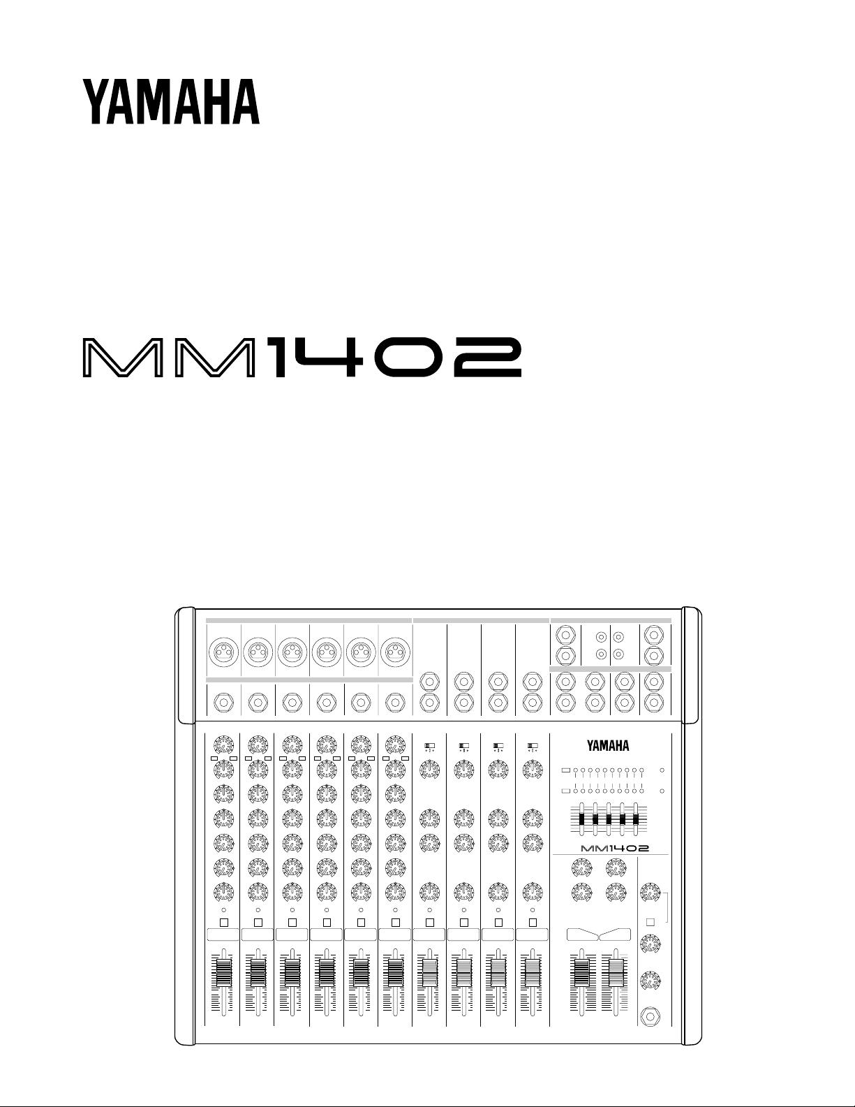
■ Channel control section (mono input section)
1 GAIN control
Use this knob to adjust the level of the input signal to the optimal level.
For the best balance of S/N ratio and dynamic range, adjust this knob so that
the peak indicator 5 lights occasionally.
For mic inputs connected to the XLR connector, the range is –14dB – –60dB.
1
For line inputs connected to the phone connector, the range is +10 – –36dB.
–14 –60
GAIN
+10 –36
–15 +15
HIGH
2 HIGH, MID, LOW equalizer (3 band)
2
–15 +15
MID
–15
+15
LOW
010
AUX 1
010
AUX 2
3
3 AUX 1, 2 controls
4 PAN control (panpot)
5 PEAK indicator
4
LR
PAN
PEAK
PFL
5
6
6 PFL switch (input channel)
1
7 Channel fader
10
5
0
7
5
10
15
20
30
00
2
These knobs control high, mid and low equalization at the following frequencies.
HIGH: 12kHz, maximum effect ±15dB
MID: 2.5kHz, maximum effect ±15dB
LOW: 80Hz, maximum effect ±15dB
When the knob is in the center position, the response will be flat.
These knobs control the level of the signal that is output to the AUX buses.
Since AUX1 is placed before the channel fader, it will be unaffected by the
position of the channel fader. Since AUX2 is placed after the channel fader, it
will be affected by the channel fader level. By outputting a signal only from
AUX SEND 1 or AUX SEND 2 and not from the ST OUT jacks, you can also
use these as supplementary outputs.
This knob assigns the signal of each channel to the STEREO L and R buses,
determining the stereo location of the sound.
This indicator detects the level of the signal at a point after the EQ (pre fader).
It will light red at 3dB before clipping to warn that the signal is approaching
clipping level.
This switch allows you to monitor the signal of the input channel at the pre
fader level. You can use headphones or MONI OUT to conveniently check
the input signal of a specific channel, or trouble-shoot a channel that is having
problems.
This fader controls the output level of the input channel signal, adjusting the
volume balance between channels. Faders of channels not in use should be
pulled down.
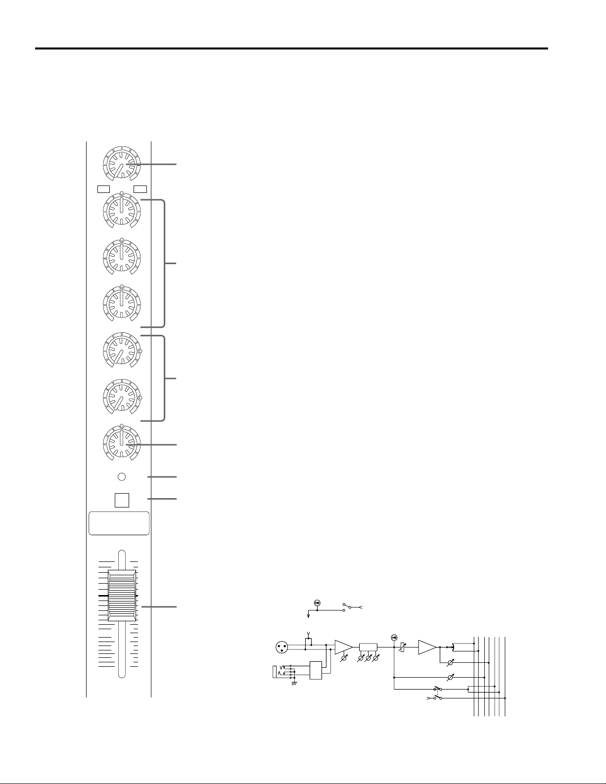
■ (Stereo input section)
BALANCE
PEAK
LOW
HIGH
AUX 1
L/MONO
PFL
(+V)
BA
BA
–20dB
–10dB
+4dB
EQHA
HA EQ
R
7–14
LINE IN
PFL CTRL
R
L
PFL
2
1
AUX
R
L
STEREO
+4dB –20dB
–10dB
–15 +15
HIGH
8
9
8 GAIN select switch
Use this switch to adjust the sensitivity of the input as appropriate for the level
of the input signal.
For the best balance of S/N ratio and dynamic range, adjust this switch so that
the peak indicator B lights occasionally.
9 HIGH, LOW equalizer (2 band)
These knobs control high mid and low equalization at the following frequencies.
HIGH: 12kHz, maximum effect ±15dB
LOW: 80Hz, maximum effect ±15dB
When the knob is in the center position, the response will be flat.
0 AUX1 control
This knob controls the level of the signal that is output to the AUX bus. Since
AUX1 is placed before the channel fader, it will be unaffected by the position
of the channel fader. By outputting a signal only from AUX SEND 1 and not
from the ST OUT jacks, you can also use this as a supplementary output.
–15
LOW
+15
0
010
AUX 1
A
LR
BALANCE
PEAK
PFL
7
8
10
5
0
B
C
D
5
10
15
20
30
00
A Balance control
This knob adjusts the left/right location of the stereo input signal.
B PEAK indicator
This indicator detects the level of the signal at a point after the EQ (pre fader).
It will light red at 3dB before clipping to warn that the signal is approaching
clipping level.
C PFL switch (input channel)
This switch allows you to monitor the signal of the input channel at the pre
fader level. You can use headphones or MONI OUT to conveniently check
the input signal of a specific channel, or trouble-shoot a channel that is having
problems.
D Channel fader
This fader controls the output level of the input channel signal, adjusting the
volume balance between channels. Faders of channels not in use should be
pulled down.
3
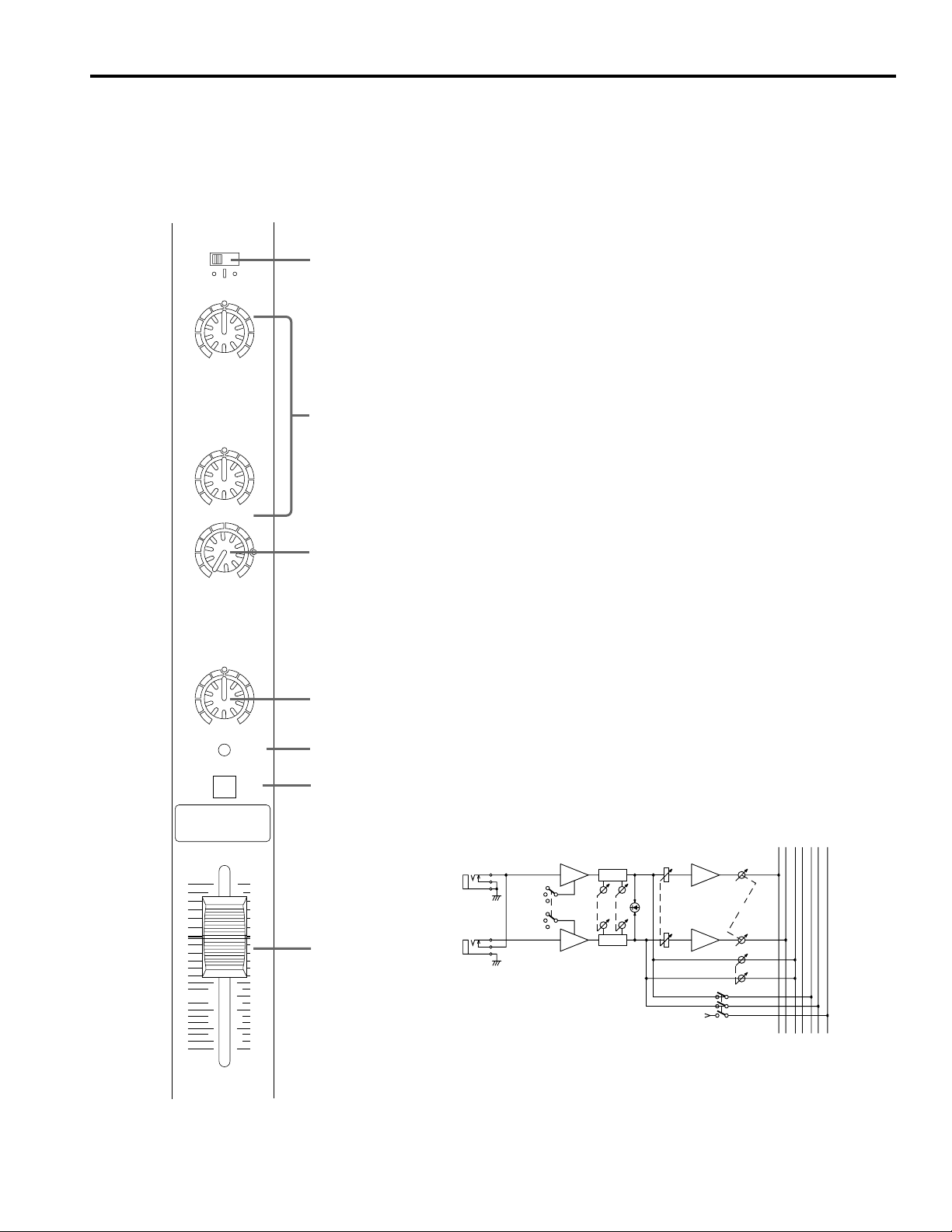
■ Master control section
L
K
G
F
00 –20 –15 –10 –6 –3 0 +2 +4 +6
R
STEREO GRAPHIC EQUALIZER
+12
9
6
3
0
3
6
9
–12
100 400 1k 5k 10k
MIXER
STEREO
010
AUX SEND 2
010
AUX RETURN 2
010
AUX SEND 1
010
AUX RETURN 1
L
10
5
0
5
10
15
20
30
00
R
PHANTOM
PFL
+12
9
6
3
0
3
6
9
–12
010
TAPE IN
TO
MONI
010
MONITOR
010
PHONES
J
I
H
L
M
N
O
P
E ST L, R master control
These faders adjust the final level of all channels, and
output the combined signal to the ST OUT jacks. The
OUTPUT LEVEL L, R meters allow you to monitor the L
and R outputs.
F AUX RETURN 1-2 controls
The knobs control the input levels from the effect units
etc. connected to AUX RETURN. Since the signals input
at AUX RETURN pass through this control and are then
output from the ST OUT jacks, AUX RETURN can be
used not only to input the signals from effect units but also
as supplementary inputs.
L/MONO
AUX RETURN
1,2
–10dB
R
HA
AUX RETURN 1,2
HA
G AUX SEND 1, 2 controls
These knobs adjust the level of the signals that are output
to AUX SEND 1 and 2.
H Graphic equalizer (5 band)
Since this equalizer is placed before ST OUT, it allows
you to make fine adjustments in equalization to the overall
output, for sound field compensation or to prevent
feedback.
I PFL indicator
This indicator will light when a PFL switch is turned ON.
J PHANTOM indicator
This indicator will light when the PHANTOM switch is
ON.
K OUTPUT LEVEL L, R meters
These meters indicate the output level to the ST OUT
jacks.
L TAPE input control
This knob controls the input signal of the tape deck etc.
that is connected to the TAPE IN jacks.
E
4
M TAPE INPUT select switch
This switch selects the destination of the input signal of
the tape deck etc. that is connected to the TAPE IN jacks.
OFF:sent to the stereo bus
ON: sent to MONI OUT (L, R)
N MONITOR control
This knob adjusts the output level from the MONI OUT
jacks.
O PHONES control
This knob adjusts the volume of the headphones
connected to the headphone jack.
P PHONE jack
A set of stereo headphones can be connected to this jack.
Normally, the headphones will monitor the same signal as
the STEREO OUT jacks, but the following two signals
can also be monitored.
1. When a 8
PFL switch is turned on, the signal of the
input channel after the equalizer will be monitored.
2. When the M TAPE input select switch is turned on, the
signal input to the TAPE IN jacks will be monitored.
BA
TAPE IN
BA
TAPE IN
–10dBV
HAL
R
HA
TO MONI
STEREO
L
1
R
AUX
2
PFL
L
R
PFL CTRL
SUM
SUM
SUM
SUM
(ST L)
(ST R)
100
GEQ
400
GEQ
METER
INV
5k
1k
10k
INV
AUX SEND 1
AUX SEND 2
PFL
MONITOR
(MONI)
METER
(MONI)
PAD
PAD
L
ST OUT
+4dB
R
L
REC OUT
–10dBV
R
1
AUX SEND
+4dB
2
L
MONI OUT
+4dB
R
L/MONO
AUX RETURN
1,2
–10dB
SUB IN
+4dB
HA
AUX RETURN 1,2
R
L
R
HA
INVSUM
SUM INV
PHONES
5
Panel
1
MIC IN
123456
LINE IN
2
1 MIC IN
These are XLR type connectors to which microphones can
be connected (1: GND, 2: hot, 3: cold). The nominal impedance is 50–600Ω.
Turn the PHANTOM switch ON to apply +48V DC to Pin
2 and 3 of MIC IN connectors 1–6.
2 LINE IN (1–6)
These are balanced phone connectors to which line-level
equipment can be connected (T: hot, R: cold, S: GND).
The nominal impedance is 600Ω.
3 LINE IN (7L–14R)
These are unbalanced phone jacks to which line level
devices can be connected. They are used as four sets of
stereo inputs (7L, 8R)–(13L, 14R). If only the L jack is
used, the input signal will be mono and the same signal
will be input to the R jack as well.
4 AUX SEND (1, 2)
These are unbalanced phone jacks.
The nominal output level and nominal impedance are
+4dB/600Ω.
5 AUX RTN (1, 2)
These are unbalanced phone jacks.
The nominal output level and nominal impedance are –
10dB/600Ω. They are used as two sets of stereo inputs
(1L, 1R)–(2L, 2R). If only the L jack is used, the input signal will be mono and the same signal will be input to the R
jack as well.
6 MONI OUT (L, R)
These are unbalanced phone jacks to which the power
amp driving your monitor speakers can be connected.
They output the same signal as the PHONE jack located
on the control panel.
7 ST OUT (L, R)
These are unbalanced phone jacks to which the power
amp driving your main speakers can be connected.
7890
LINE IN
7L
MONO
654321
8R
MONO
9L
10R
MONO
11L
12R
3
Phantom Power Warning
To prevent hazard or damage, connect only
microphones and cables that conform to the
IEC288-15A standard.
8 REC OUT (L, R)
These jacks output the signal from before the ST OUT (L,
R) faders.
9 TAPE IN (L, R)
These jacks are used as inputs for a sound source such as a
tape recorder.
0 SUB IN (L, R)
These are supplementary inputs. The signal input here is
sent to the stereo bus.
SUB IN +4dB TAPE IN –10dBV REC OUT –10dBV ST OUT +4dB
LRL
MONO
1L
1R
5
R
2L
MONO
2R
4
AUX RETURN –10dB AUX SEND +4dB MONI OUT +4dB
13L
MONO
14R
L
R
1
2
L
R
L
R
6
AB
POWER PHANTOM
ON
OFF
A POWER switch
This switch turns the power on.
B PHANTOM switch
This switch turns the phantom power on/off for all
channels.
Use this when you are using condenser microphones.
When this switch is turned on, DC +48 V will be supplied
to pins 2 and 3 of each input MIC IN 1–6.
If your microphones do not require phantom power, be
sure to turn this switch off.
* Although it is safe to connect balanced dynamic micro-
phones or line level devices when the PHANTOM
switch is on, connecting unbalanced devices or devices
whose transformer is center grounded will cause hum
or malfunctions.
ON
OFF
6
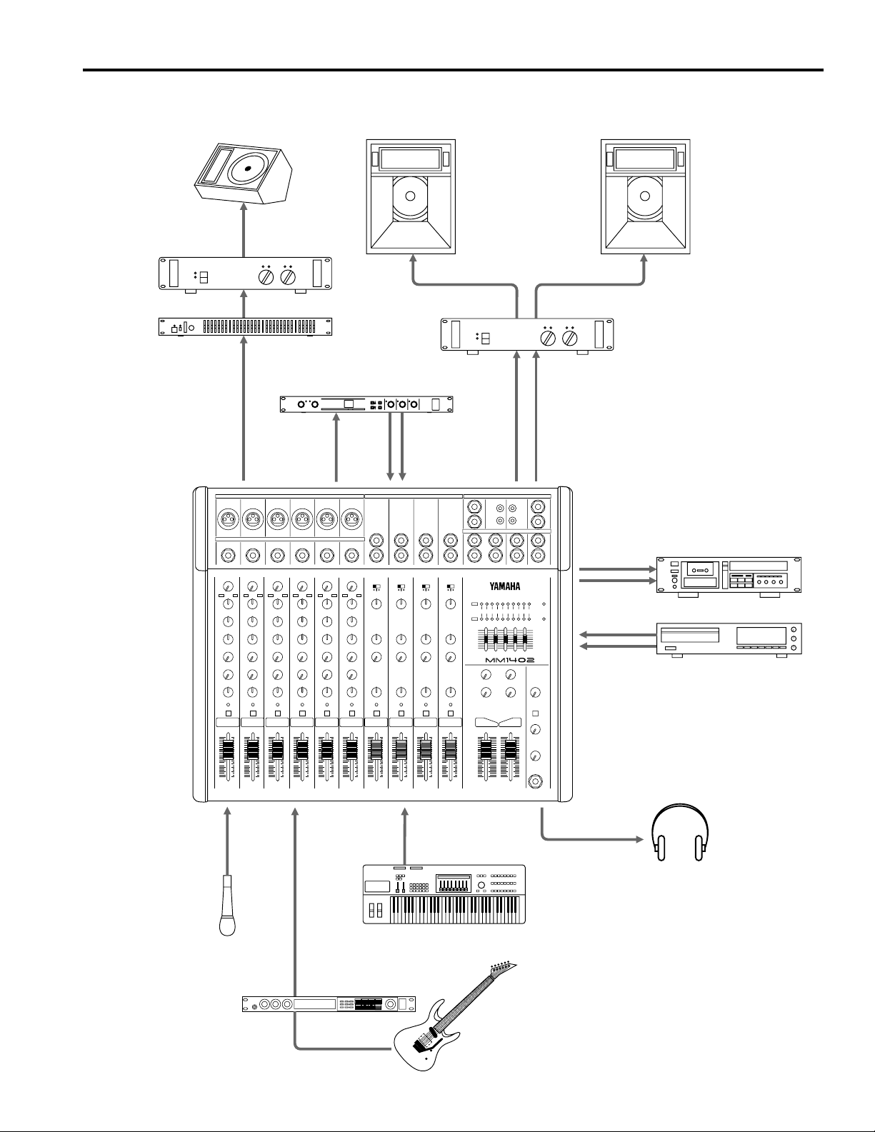
Application Example
Stage Monitors
Power Amp
Front of House
Main Speakers
Graphic EQ
AUX SEND1
Effects Processor
AUX SEND2
Power Amp
AUX RETURN L/R
MIXER
STEREO OUT
Cassette Recorder
REC OUT L/R
CD Player
TAPE IN L/R
MIC IN
Mics
LINE IN
L/R
Guitar Effect Processor
LINE IN
L/R
Line Level Sources
Headphones
HEAD PHONES
7
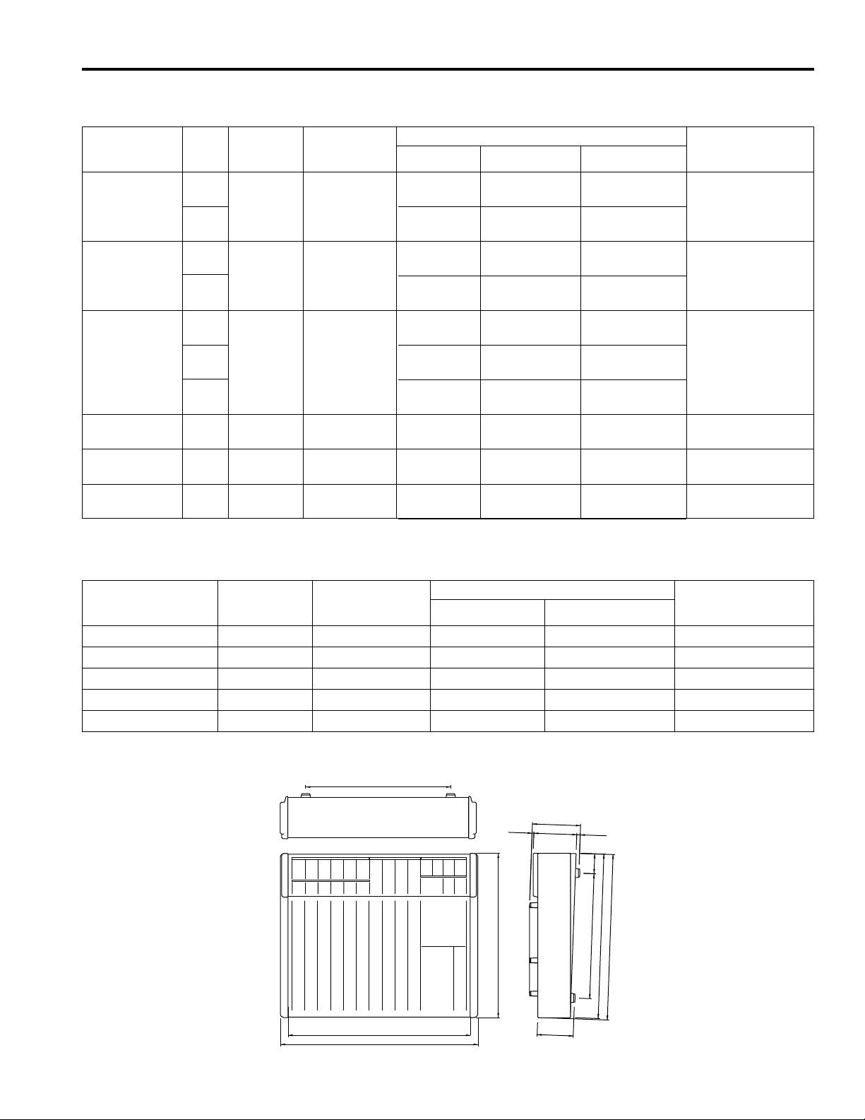
Specifications
■ General Specifications
Maximum output level +20dB* (ST OUT L/R) @600Ω, 0.5% THD at 1kHz
+20dB* (AUX SEND 1–2) @600Ω, 0.5% THD at 1kHz
Total harmonic distortion < 0.1% @+14dB* 20Hz–20kHz (ST OUT L/R @600Ω, AUX SEND 1–2 @600Ω)
Frequency response 20Hz–20kHz +1dB, –2dB @+4dB* (ST OUT L/R @600Ω, AUX SEND 1–2 @600Ω)
Hum and noise –127dB* Equivalent input noise (INPUT 1–6)
(Average, Rs=150Ω) –95dB* Residual output noise (ST OUT L/R @600Ω, AUX SEND 1–2 @600Ω)
(20Hz–20kHz)
Maximum voltage gain 84dB INPUT (1–6) → ST OUT
–78dB*(ST OUT L/R) Master fader: nominal
All channel fader: minimum
–63dB*(67dB S/N)(ST OUT L/R) Master fader: nominal
One channel fader: nominal
–78dB*(AUX SEND 1–2) Master level control: nominal
All channel AUX level control: minimum
–63dB*(67dB S/N)(AUX SEND 1–2) Master level control: nominal
One channel fader:
One channel AUX control: nominal
44dB INPUT (7L–14R) → ST OUT
76dB INPUT (1–6) → AUX SEND1
86dB INPUT (1–6) → AUX SEND2
62dB INPUT (1–6) → REC OUT
70dB INPUT (1–6) → MONITOR OUT (PFL SW ON)
30dB AUX RETURN → ST OUT
10dB SUB IN → ST OUT
28dB TAPE IN → ST OUT
Crosstalk –70dB @ 1kHz adjacent input channels
–70dB @ 1kHz adjacent output channels
Gain control (1–6) 46dB variable range
INPUT (7L–14R) Input Level Selector
INPUT (1–6) ±15dB maximum boost or cut
Channel equalization HIGH 12kHz shelving
INPUT (7L–14R) ±15dB maximum boost or cut
Channel equalization HIGH 12kHz shelving
ST OUT Graphic EQ ±12dB at 100, 400, 1k, 5k, 10kHz
LED meters 0dB=+4dB* Output level
Channel PEAK indicators Red LED on each channel lights when post-EQ signal reaches 3dB below clip level.
Phantom power +48V, DC
Power requirements US & Canadian Models: AC 120V, 60Hz
Power consumption US & Canadian Models: 40W
Dimensions (W × H × D) 430 × 104.9 × 360.1 mm
+4/–10/–20dB*
MID 2.5kHz peaking
LOW 80Hz shelving
LOW 80Hz shelving
General Model: AC 230V, 50Hz
General Model: 40W
Weight 6.5kg
* 0dB=0.775Vrms.
8
■ Input Specifications
Input
MIC IN microphone (77.5µV) (775µV) (7.75mV) Balanced
(1–6) MIN –34dB –14dB +6dB
LINE IN (1.23mV) (12.3mV) (0.123V) Balanced
(1–6) MIN –10dB +10dB +30dB
INPUT
(7L–14R)
AUX RETURN
(1L–2R) (38.8V) (0.245V) (7.75V) Unbalanced
SUB IN
(L/R) (0.388V) (1.23V) (12.3V) Unbalanced
TAPE IN
(L/R) (50.1mV) (316mV) (7.75V) Unbalanced
Gain Input Nominal
Trim impedance impedance Sensitivity Nominal level
MAX 2.5kΩ 50–600Ω –80dB –60dB –40dB XLR-3-31 type
(15.5mV) (0.155V) (1.55V)
MAX 47kΩ 600Ω line –56dB –36dB –16dB Phone jack
(0.245V) (2.45V) (24.5V)
–20 10kΩ 600Ω line –40dB –20dB 0dB Phone jack
–10 –30dB –10dB +10dB
+4 –16dB +4dB +24dB
—
—
—
10kΩ 600Ω line –26dB –10dB +20dB Phone jack
10kΩ 600Ω line –6dB +4dB +24dB Phone jack
10kΩ 600Ω line –26dBV –10dBV +18dBV RCA pin jack
(7.75mV) (77.5mV) (0.775V) Unbalanced
(24.5mV) (0.245V) (2.45V)
(0.123V) (1.23V) (12.3V)
Input level
Maximum non-
clipping level
Connector type
1=GND
2=hot
3=cold
T=hot
R=cold
S=GND
0dB=0.775Vrms., 0dBV=1Vrms
■ Output Specifications
Output
ST OUT (L/R) 75Ω 600Ω Lines +4dB (1.23V) +20dB (7.75V) Phone jack
AUX SEND (1–2) 75Ω 600Ω Lines +4dB (1.23V) +20dB (7.75V) Phone jack
MONITOR OUT (L/R) 75Ω 600Ω Lines +4dB (1.23V) +20dB (7.75V) Phone jack
REC OUT (L/R) 600Ω 10Ω Lines –10dBV (316mV) +10dBV (3.16V) RCA pin jack
HEAD PHONE 100Ω 40Ω Phones 3mW 120mW Stereo phone jack
Output Nominal
impedance impedance Nominal level
0dB=0.775Vrms., 0dBV=1Vrms
Outputs are unbalanced
318
Output level
Maximum non-
clipping level
Connector type
■ Dimensions
H:104.9
3.9
93.4
357.4
7.6
43.2
271.8
357.6
D:360.1
Specifications and appearance subject to change without notice.
397
W:430
78.5
Units: mm
9
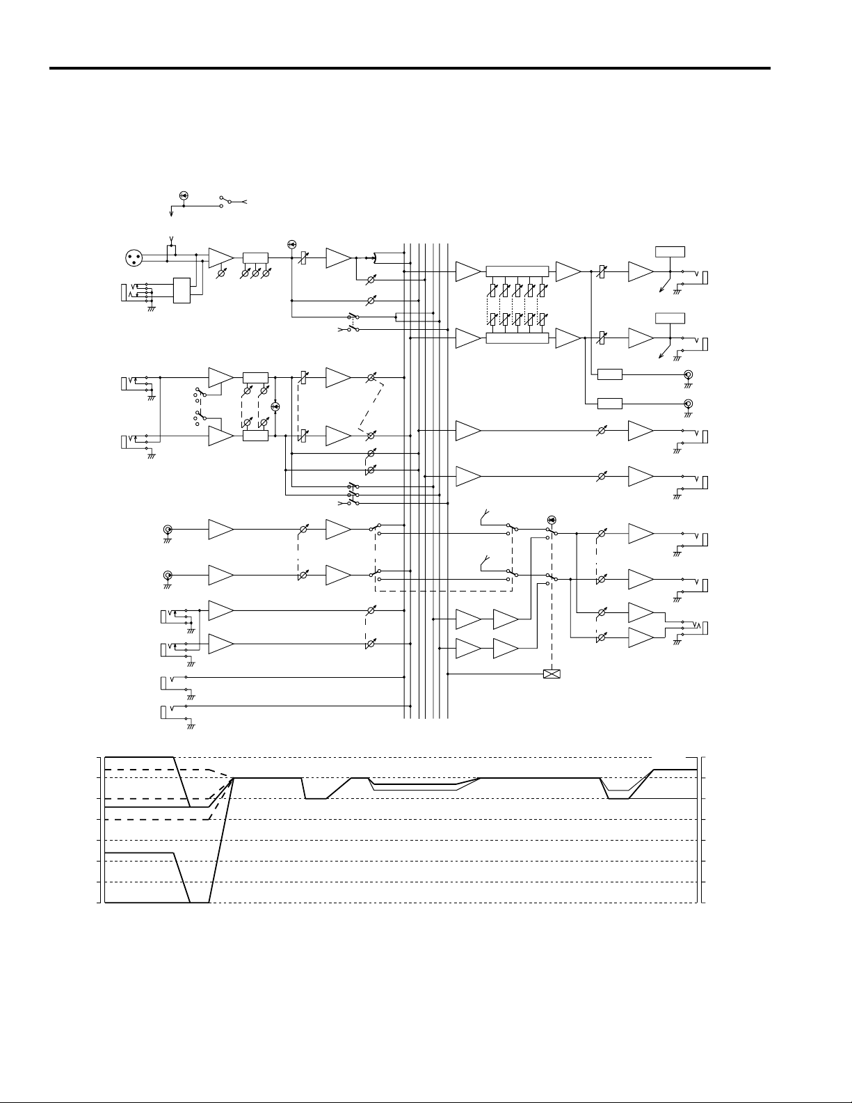
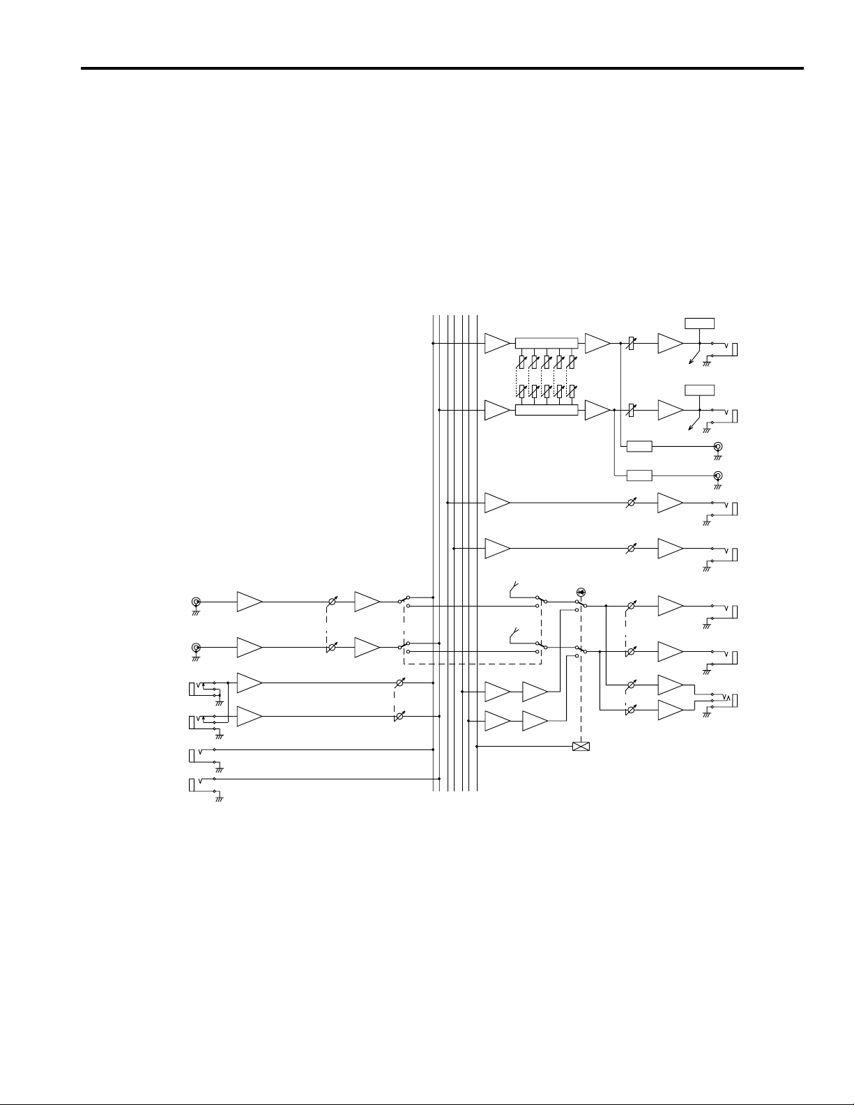
■ Block and Level Diagrams
PHANTOM
MIC IN
1–6
LINE IN
1–6
L /MONO
LINE IN
7–14
R
TAPE IN
–10dBV
(MIC IN)
(PHANTOM)
PAD
+4dB
–10dB
–20dB
R
OFF
ON
PHANTOM
HA
GAIN
HA EQ
HAL
HA
EQ
LOW
LOW
EQHA
(+48V)
MID
HIGH
HIGH
PEAK
PEAK
TAPE IN
(+V)
(+V)
PFL
STEREO
AUX
L
BA
PAN
AUX 2
AUX 1
PFL
BA
BALANCE
BA
AUX 1
PFL
BA
TO MONI
BA
PFL CTRL
L
2
1
R
R
METER
SUM
SUM
SUM
SUM
(ST L)
(ST R)
100
GEQ
400
GEQ
INV
5k
1k
10k
INV
AUX SEND 1
AUX SEND 2
PFL
MONITOR
(MONI)
METER
(MONI)
PAD
PAD
L
ST OUT
+4dB
R
L
REC OUT
–10dBV
R
1
AUX SEND
+4dB
2
L
MONI OUT
+4dB
R
AUX RETURN
SUB IN
+4dB
[dB]
+10
0
–10
–20
–30
–40
–50
–60
L/MONO
1,2
–10dB
R
L
R
LINE IN 1–6[+10]
LINE IN 7–14[+4]
LINE IN 7–14[–10]
MIC IN[–14]
LINE IN 7–14[–20]
LINE IN 1–6[–36]
MIC IN[–60]
HA
AUX RETURN 1,2
HA
ST
AUX
INVSUM
SUM INV
PHONES
AUX
ST
ST OUT
AUX SEND
[dB]
+10
0
–10
–20
–30
–40
–50
–60
10

MELANGEUR
MANUEL D’INSTRUCTIONS
Français
 Loading...