

Yamaha Audio MM1242 User Manual
MIXER
MELANGEUR
MISCHPULTE
MEZCLA
Operation Manual
Manuel d’instructions
Bedienungsanleitung
Manual de Operación
GAIN
GAIN
GAIN
GAIN
+10 –16
+10 –16
+10 –16
LINE
MIC
HIGH
HIMID
LOMID
LOW
AUX
1
AUX
2
AUX
3
AUX
4
PAN
–15 +15
–12 +12
–12 +12
–15 +15
0 10
0 10
0 10
0 10
L R
PFL
–60 –26
–60 –26
LINE
MIC
HIGH
–15 +15
HIMID
–12 +12
LOMID
–12 +12
LOW
–15 +15
AUX
1
P
0 10
O
AUX
S
2
T
0 10
AUX
3
P
0 10
R
AUX
E
4
0 10
PAN
L R
PEAK
PEAK
PFL
10
5
0
5
10
15
20
30
40
00
+10 –16
–60 –26
–15 +15
–12 +12
–12 +12
–15 +15
0 10
0 10
0 10
0 10
L R
PFL
–60 –26
LINE
MIC
HIGH
–15 +15
HIMID
–12 +12
LOMID
–12 +12
LOW
–15 +15
AUX
1
P
P
0 10
O
O
AUX
S
S
2
T
T
0 10
AUX
3
P
P
0 10
R
R
AUX
E
E
4
0 10
PAN
L R
PEAK
PEAK
PFL
10
10
5
5
0
0
5
5
10
10
15
15
20
20
30
30
40
40
00
00
LINE
MIC
HIGH
HIMID
LOMID
LOW
AUX
1
P
O
AUX
S
2
T
AUX
3
P
R
AUX
E
4
PAN
10
5
0
5
10
15
20
30
40
00
12345678910 11 12
GAIN
+10 –16
LINE
MIC
HIGH
HIMID
LOMID
LOW
AUX
1
AUX
2
AUX
3
AUX
4
PAN
–15 +15
–12 +12
–12 +12
–15 +15
0 10
0 10
0 10
0 10
L R
PFL
GAIN
GAIN
GAIN
GAIN
GAIN
GAIN
GAIN
+10 –16
+10 –16
+10 –16
+10 –16
+10 –16
+10 –16
–60 –26
–60 –26
–60 –26
–60 –26
–60 –26
–15 +15
–12 +12
–12 +12
–15 +15
0 10
0 10
0 10
0 10
L R
PFL
–60 –26
LINE
MIC
HIGH
–15 +15
HIMID
–12 +12
LOMID
–12 +12
LOW
–15 +15
AUX
1
P
0 10
O
AUX
S
2
T
0 10
AUX
3
P
0 10
R
AUX
E
4
0 10
PAN
L R
PEAK
PEAK
PFL
10
5
0
5
10
15
20
30
40
00
LINE
LINE
LINE
MIC
MIC
HIGH
HIGH
–15 +15
–15 +15
HI-
HI-
MID
MID
–12 +12
–12 +12
LO-
LO-
MID
MID
–12 +12
–12 +12
LOW
LOW
–15 +15
–15 +15
AUX
AUX
1
1
P
P
0 10
0 10
O
O
AUX
AUX
S
S
2
2
T
T
0 10
0 10
AUX
AUX
3
3
P
P
0 10
0 10
R
R
AUX
AUX
E
E
4
4
0 10
0 10
PAN
PAN
L R
PEAK
10
10
15
20
30
40
00
L R
PEAK
PEAK
PFL
PFL
10
5
5
0
0
5
5
10
15
20
30
40
00
LINE
MIC
MIC
HIGH
HIGH
–15 +15
HI-
HI-
MID
MID
–12 +12
LO-
LO-
MID
MID
–12 +12
LOW
LOW
–15 +15
AUX
AUX
1
1
P
P
0 10
O
O
AUX
AUX
S
S
2
2
T
T
0 10
AUX
AUX
3
3
P
P
0 10
R
R
AUX
AUX
E
E
4
4
0 10
PAN
PAN
L R
PEAK
PFL
10
10
5
5
0
0
5
5
10
10
15
15
20
20
30
30
40
40
00
00
+10 –16
–60 –26
–15 +15
–12 +12
–12 +12
–15 +15
0 10
0 10
0 10
0 10
L R
PFL
HIGH
HIMID
LOMID
LOW
AUX
1
P
O
AUX
S
2
T
AUX
3
P
R
AUX
E
4
PAN
PEAK
10
5
0
5
10
15
20
30
40
00
–60 –26
LINE
MIC
–15 +15
–12 +12
–12 +12
–15 +15
P
0 10
O
S
T
0 10
AUX SEND 1
P
0 10
0 10
R
E
0 10
0 10
0 10
L R
AUX RETURN 1
PEAK
PFL
PFL PFL
10
5
0
5
10
15
20
30
40
00
LINE
MIC
HIGH
HIMID
LOMID
LOW
AUX
1
P
O
AUX
S
2
T
AUX
3
P
R
AUX
E
4
PAN
10
5
0
5
10
15
20
30
40
00
MIXER
PHANTOM POWER
AUX 3 AUX 4
OUTPUT LEVEL
AUX SEND 2
0 10
L
0 10
R
0 10
AUX RETURN 2
10
5
0
5
10
15
20
30
40
00
+6
+4
+2
0
–2
–4
–7
–10
–15
–20
MONITOR
0 10
0 10
0 10
AUX RETURN 3
PFL
L
R
10
5
0
5
10
15
20
30
40
00
AUX RETURN 4
PFL
+6
+4
+2
0
–2
–4
–7
–10
–15
–20
L R
L
R
10
5
0
5
10
15
20
30
40
00
L ST R 3 AUX SEND 4
LEVEL
0 10
0 10
0 10
POWER
PHONES
ON
OFF
L
R
10
5
0
5
10
15
20
30
40
00

FCC INFORMATION (U.S.A.)
1. IMPORTANT NOTICE: DO NOT MODIFY THIS UNIT!
This product, when installed as indicated in the instructions contained in this manual, meets FCC requirements. Modifications not expressly approved by
Yamaha may void your authority, granted by the FCC, to use the product.
2. IMPORTANT: When connecting this product to accessories and/or another product use only high quality shielded cables. Cable/s supplied with this product
MUST be used. Follow all installation instructions. Failure to follow instructions could void your FCC authorization to use this product in the USA.
3. NOTE: This product has been tested and found to comply with the requirements listed in FCC Regulations, Part 15 for Class “B” digital devices. Compliance
with these requirements provides a reasonable level of assurance that your use of this product in a residential environment will not result in harmful interference
with other electronic devices. This equipment generates/uses radio frequencies and, if not installed and used according to the instructions found in the users
manual, may cause interference harmful to the operation of other electronic devices. Compliance with FCC regulations does not guarantee that interference
will not occur in all installations. If this product is found to be the source of interference, which can be determined by turning the unit “OFF” and “ON”, please
try to eliminate the problem by using one of the following measures:
Relocate either this product or the device that is being affected by the interference
Utilize power outlets that are on different branch (circuit breaker of fuse) circuits or install AC line filter/s.
In the case of radio or TV interference, relocate/reorient the antenna. If the antenna lead-in is 300 ohm ribbon lead, change the lead-in to coaxial type cable.
If these corrective measures do not produce satisfactory results, please contact the local retailer authorized to distribute this type of product. If you can not locate
the appropriate retailer, please contact Yamaha Corporation of America. Electronic Service Division, 6600 Orangethorpe Ave, Buena Park, CA 90620
This applies only to products distributed by YAMAHA CORPORATION OF AMERICA
*
Dette apparat overholder det gaeldende EF-direktiv vedtrørende
radiostøj.
Cet appareil est conforme aux prescriptions de la directive
communautaire 87/308/CEE.
Diese Geräte entsprechen der EG-Richtlinie 82/499/EWG und/
oder 87/308/EWG.
This product complies with the radio frequency interference requirements of the Council Directive 82/499/EEC and/or 87/308/
EEC.
Questo apparecchio è conforme al D.M.13 aprile 1989 (Direttiva
CEE/87/308) sulla soppressione dei radiodisturbi.
Este producto está de acuerdo con los requisitos sobre interferencias
de radio frequencia fijados por el Consejo Directivo 87/308/CEE.
YAMAHA CORPORATION
IMPORTANT NOTICE FOR
THE UNITED KINGDOM
Connecting the Plug and Cord
WARNING: THIS APPARATUS MUST BE EARTHED
IMPORTANT: The wires in this mains lead are coloured in accordance with
the following code:
GREEN-AND-YELLOW : EARTH
BLUE : NEUTRAL
BROWN : LIVE
As the colours of the wires in the mains lead of this apparatus may not
correspond with the coloured markings idenlifying the terminals in your
plug, proceed as follows:
The wire which is coloured GREEN and YELLOW must be connected to the
terminal in the plug which is marked by the letter E or by the safety earth
symbol or coloured GREEN and YELLOW.
The wire which is coloured BLUE must be connected to the terminal which
is marked with the letter N or coloured BLACK.
The wire which is coloured BROWN must be connected to the terminal
which is marked with the letter L or coloured RED.
This applies only to products distributed by YAMAHA KEMBLE MUSIC (U.K.)
*
LTD.
CANADA
THIS DIGITAL APPARATUS DOES NOT EXCEED THE “CLASS
B” LIMITS FOR RADIO NOISE EMISSIONS
FROM DIGITAL APPARATUS SET OUT IN THE RADIO INTERFERENCE REGULATION OF THE CANADIAN DEPARTMENT
OF COMMUNICATIONS.
LE PRESENT APPAREIL NUMERIQUE N’EMET PAS DE BRUITS
RADIOELECTRIQUES DEPASSANT LES LIMITES APPLICABLES
AUX APPAREILS NUMERIQUES DE LA “CLASSE B”
PRESCRITES DANS LE REGLEMENT SUR LE BROUILLAGE
RADIOELECTRIQUE EDICTE PAR LE MINISTERE DES COMMUNICATIONS DU CANADA.
This applies only to products distributed by YAMAHA CANADA
*
MUSIC LTD.
Litiumbatter!
Bör endast bytas av servicepersonal.
Explosionsfara vid felaktig hantering.
VAROITUS!
Lithiumparisto, Räjähdysvaara.
Pariston saa vaihtaa ainoastaan aian
ammattimies.
ADVARSELl!
Lithiumbatter!
Eksplosionsfare. Udskiftning må kun foretages
af en sagkyndig, –og som beskrevet i
servicemanualen.

Introduction
Congratulations! You are now the proud owner of a Yamaha MM1242 Mixer. Your Yamaha
mixing console is a high-quality product which combines ease of operation, functionality,
and convenience and will give you superior performance in a wide range of applications.
MM1242 also features the great sound for which Yamaha is famous. Please read this
operation manual thoroughly in order to make the most of the mixer’s many features and
controls.
Features
● Twelve input channels and stereo mix output
● PFL (Pre Fader Listen) function allows you to monitor any channel input and ST L, R AUX
3, 4 output through monitor output or headphones.
● All input channels are available for both microphone level input and line-level input,
making connections very easy.
● Built-in phantom power allows you to connect condenser microphones.
● Four AUX SEND connectors and four ST AUX RTN connectors allow you to connect up
to four external effects units.
Contents
Precautions ............................................................................1
Front Panel Controls..............................................................2
Input Channel...................................................................2
Master Section .................................................................4
Rear Panel ........................................................................6
Application Example .............................................................7
Specifications ........................................................................ 8
General Specifications ..................................................... 8
Input Specifications .........................................................9
Output Specifications.......................................................9
Dimensions ......................................................................9
Block and Level Diagrams ............................................ 10

Precautions
1. Location
Keep the unit away from locations where it is likely to be
exposed to high temperatures or humidity — such as near
radiators, stoves, etc. Also avoid locations which are
subject to excessive dust accumulation or vibration which
could cause mechanical damage and locations subject to
strong electromagnetic fields, such as close to broadcast
equipment.
2. Ventilation
The unit has ventilation slots on the side and bottom
panels. Do not block these vents.
3. Avoid Physical Shocks
Strong physical shocks to the unit can cause damage.
Handle it with care.
4. Do Not Open the Case or Attempt Repairs or Modifications Yourself
This product contains no user-serviceable parts. Refer all
maintenance to qualified Yamaha service personnel.
Opening the case and/or tampering with the internal
circuitry voids the warranty.
5. Always power off before making connections
Always turn the power OFF before connecting or disconnecting cables. This is important to prevent damage to the
unit itself as well as other connected equipment.
6. Handle Cables Carefully
Always plug and unplug cables — including the AC
power cord — by gripping the connector, not the cord.
7. Clean With a Soft Dry Cloth
Never use solvents such as benzine or thinner to clean the
unit. Wipe clean with a soft, dry cloth.
8. Always Use the Correct Power Supply
Make sure that the power supply voltage specified on the
rear panel matches your local AC mains supply. Also
make sure that the AC mains supply can deliver more than
enough current to handle all equipment used in your
system.
Dette apparat overholder det gaeldende EF-direktiv vedtrørende
radiostøj.
Cet appareil est conforme aux prescriptions de la directive
communautaire 87/308/CEE.
Diese Geräte entsprechen der EG-Richtlinie 82/499/EWG und/
oder 87/308/EWG.
This product complies with the radio frequency interference requirements of the Council Directive 82/499/EEC and/or 87/308/
EEC.
Questo apparecchio è conforme al D.M.13 aprile 1989 (Direttiva
CEE/87/308) sulla soppressione dei radiodisturbi.
Este producto está de acuerdo con los requisitos sobre interferencias
de radio frequencia fijados por el Consejo Directivo 87/308/CEE.
YAMAHA CORPORATION
IMPORTANT NOTICE FOR
THE UNITED KINGDOM
Connecting the Plug and Cord
IMPORTANT: The wires in this mains lead are coloured in accordance with
the following code:
BLUE : NEUTRAL
BROWN : LIVE
As the colours of the wires in the mains lead of this apparatus may not
correspond with the coloured markings identifying the terminals in your
plug, proceed as follows:
The wire which is coloured BLUE must be connected to the terminal which
is marked with the letter N or coloured BLACK.
The wire which is coloured BROWN must be connected to the terminal
which is marked with the letter L or coloured RED.
Making sure that neither core is connected to the earth terminal of the three
pin plug.
This applies only to products distributed by YAMAHA KEMBLE MUSIC (U.K.)
*
LTD.
1
Front Panel Controls
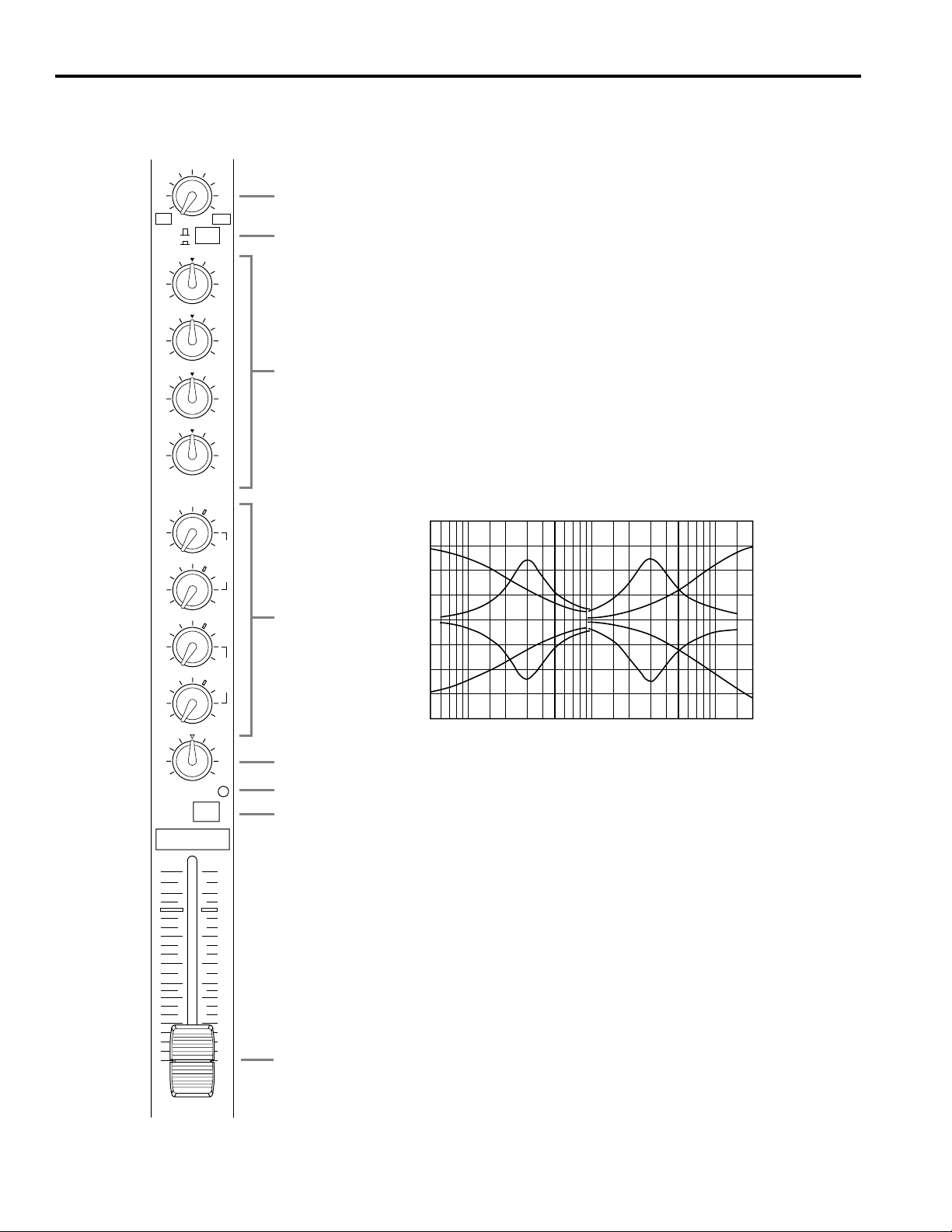
50 100 200 500 1k 2k 5k 10k 20k
FREQUENCY (Hz)
+20
+15
+10
+5
0
–5
–10
–15
–20
RESPONSE (dB)
■ Input Channel
GAIN
+10 –16
–60 –26
LINE
MIC
HIGH
–15 +15
HIMID
–12 +12
LOMID
–12 +12
LOW
–15 +15
AUX
1
0 10
AUX
2
1 GAIN control
This control adjusts the input sensitivity of each input channel from –16dB to
–60dB for microphone source through the XLR input connectors, and from
+10dB to –26dB for line source through the phone jack input connectors. For
1
2
optimum performance, adjust this GAIN control so that the PEAK indicator
LED lights occasionally.
2 LINE/MIC switch
This switch toggles between MIC IN. Push this switch in (to MIC) when a microphone is connected to the MIC IN connector. Set this switch to LINE when
a line source is connected to the LINE IN connector.
3 EQ
The equalizer section provided on each input channel consists of LOW, LO-
3
MID, HI-MID and HIGH controls at the following frequencies with the
maximum range of ±15dB.
HIGH : 12kHz
HI-MID : 3kHz
LO-MID : 300Hz
LOW : 80Hz
Frequency response will be flat when each control is set to the center.
P
O
S
T
0 10
AUX
3
PEAK
P
R
E
10
5
0
5
10
15
20
30
40
00
0 10
AUX
4
0 10
PAN
L R
PFL
2
4
5
6
7
8
4 AUX send controls
Each AUX control determines the level of the signal sent from the input
channels to the correspondingly-numbered AUX mixing bus.
• AUX 1 and AUX 2 are factory pre-wired for post-fader operation, so the
AUX 1 and AUX 2 signals are affected by the setting of the channel fader.
• AUX 3 and AUX 4 are factory pre-wired for pre-fader operation, so the
AUX 3 and AUX 4 signals are not affected by the setting of the channel
fader. Therefore, the signal can be output either to AUX 3 or AUX 4 as an
auxiliary output, instead of using the stereo outputs.
5 PAN control
The PAN control determines the position in the stereo
sound field at which the sound from that channel is heard,
by distributing signal from each channel to STEREO L
and R buses.
6 PEAK indicator
The PEAK indicator LED lights in red when the pre-EQ,
post-EQ, or post-fader signal of the corresponding
channel’s input reaches a level 3dB below the clipping
level.
7 PFL switch
Press this switch to monitor the pre-fader input channel
signal through the MONITOR OUT or the PHONES
connector.
This is useful when you wish to monitor only the signal
from a particular channel, or take a countermeasure for a
problem.
8 Fader
This is the main level control for each input channel. It determines the level of the signal sent from the
corresponding input channel to the master stereo bus. The
settings of the input channel faders determine the “mix” or
balance of sound levels between the instruments or other
sources connected to the inputs.
Lower the faders of unused channels to the bottom.
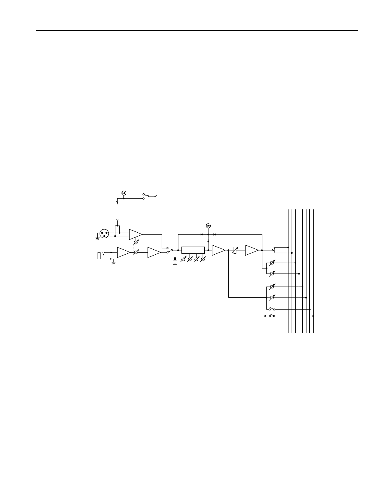
MIC IN
1-12
LINE IN
1-12
PHANTOM
(MIC IN)
(PHANTOM)
HA
OFF
ON
PHANTOM
HA
GAIN
BA
(+48V)
LINE
MIC
LOW
HI-MID
LO-MID
PEAK
HIGH
BA
AUX
STEREO
L
BAEQ
PAN
AUX 1
AUX 2
AUX 3
AUX 4
(+V)
PFL
4321R
PFL
PFL CTRL
3
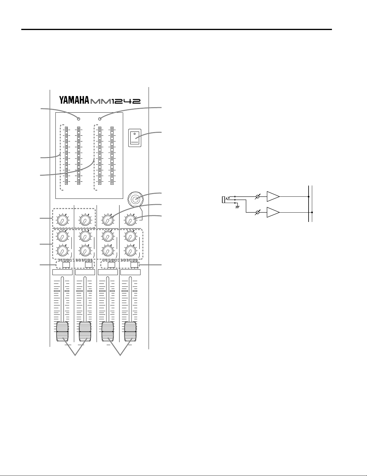
■ Master Section
1 ST faders
The stereo master faders independently adjust the level of
the left and right channel main stereo buss signals
appearing at the STEREO OUT connectors.
The OUTPUT LEVEL L, R meters allow you to monitor
the L and R outputs.
7
6
5
4
3
2
MIXER
PHANTOM POWER
+6
+4
+2
0
–2
–4
–7
–10
–15
–20
L R
OUTPUT LEVEL
AUX SEND 1
0 10
0 10
0 10
AUX RETURN 1
PFL
L ST R 3 AUX SEND 4
AUX SEND 2
L
R
AUX RETURN 2
10
5
0
5
10
15
20
30
40
00
0 10
0 10
0 10
PFL
+6
+4
+2
0
–2
–4
–7
–10
–15
–20
AUX 3 AUX 4
MONITOR
0 10
L
0 10
R
0 10
AUX RETURN 3
PFL
10
5
0
5
10
15
20
30
40
00
L
R
10
5
0
5
10
15
20
30
40
00
POWER
PHONES
LEVEL
0 10
0 10
0 10
AUX RETURN 4
PFL
2 ST PFL switches
Turning this switch ON sends the pre-fader ST L and R
8
signals to the MONITOR OUT and PHONES.
3 AUX RETURN controls
These controls adjust the level of the L and R signals that
ON
OFF
9
are received at the rear-panel ST AUX RTNs 1–4. (Use a
stereo-type phone plug connector for ST AUX RTN 1–4.)
After this controls, the signals are sent to the L and R
stereo bus (STEREO OUT). Therefore, you can use the
ST AUX RTN as auxiliary inputs, as well as effects
returns.
STEREO
L R
0
A
ST AUX RTN
1〜 4 –10dB
B
L
R
4 AUX SEND controls
These adjust the overall output level appearing at AUX
SEND1 and 2.
INV
L
INV
R
5 OUTPUT LEVEL AUX 3, 4 meters
C
These meters show the level of output signal appearing at
the AUX SEND 3 and 4.
10
5
0
5
10
15
20
30
40
00
6 OUTPUT LEVEL L, R meters
These meters show the level of output signal appearing at
the STEREO OUT connector.
7 PHANTOM indicator
The PHANTOM indicator LED lights when the Phantom
power is ON.
8 POWER indicator
The POWER indicator LED lights when the power is ON.
1
D
4
9 POWER switch
Flip up to turn the power ON.
It is a rule that first you turn off the power to the devices (a
power amplifier, in many cases) closest to the speakers
before turning off the power to the console.
0 PHONES jack
Connect the headphones here.
You can monitor the following signals:
A MONITOR control
This control adjusts the level of the signal output from the
MONITOR OUT.
— Signals available for monitoring —
1. Post-EQ signal
(when the corresponding channel PFL switch is ON)
2. Pre-fader ST signal
(when the corresponding stereo L/R PFL switch is ON)
3. Pre-AUX SEND 3/4-fader signal
(when the corresponding AUX send 3/4 PFL switch is
ON)
AUX
STEREO
4321R
L
PFL
PFL CTRL
PFL
PFL
PFL
SUM
(+V)
(+V)
SUM INV
SUM
(+V)
(ST OUT)
INV
B PHONES LEVEL control
The PHONES control adjusts the level of the signal sent to
the PHONES jack.
C AUX SEND 3, 4 PFL switches
Turning this switch ON will allow you to monitor the
signal output to AUX SEND 3 and 4 via the MONITOR
OUT or headphones.
D AUX SEND 3, 4 faders
These faders adjust the AUX SEND 3 and 4 output levels.
You can also use these to adjust the level of an auxiliary
output.
METER
INVSUM
(MONITOR)
METER
INVSUM
(MONITOR)
+
+
AUX SEND 1
SUM
SUM
METER
INV
INV
MONITOR
INV
L
STEREO OUT
+4dB
R
AUX SEND
1,2 +4dB
AUX SEND
3,4 +4dB
L
MONITOR
OUT +4dB
R
INV
INV
PHONES
LEVEL
5
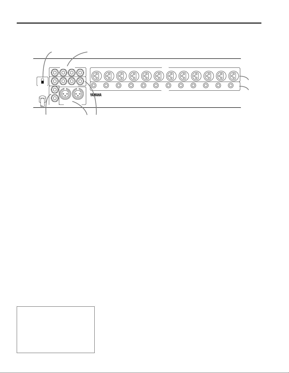
■ Rear Panel
3
12 11 10
4
5
ON
OFF
PHANTOM
6
7
AUX SEND +4dB
4321
4321
ST AUX RTN –10dB
L
R
MONITOR
OUT +4dB
RL
STEREO OUT +4dB
1 MIC IN connectors
These are XLR-type connectors to connect microphones.
(Pin assignment - 1: GND, 2: hot, 3: cold)
Impedance range is 50Ω to 600Ω.
Turn the PHANTOM switch ON to apply +48V DC to Pin
2 and 3 of these connectors.
2 LINE IN
These are unbalanced phone jacks used to connect line
sources. (Impedance: 600Ω)
3 AUX send jacks
These are unbalanced phone jacks.
(T: hot, R: cold, S: GND)
Nominal output level and impedance is +4dB/600Ω.
4 ST AUX RTN jacks
These are stereo type phone jacks.
Nominal output level and impedance is –10dB/600Ω.
Usually, the output from effects units such as delay and
reverb are returned to the main stereo mix via these jacks.
However, you can use these as auxiliary inputs.
5 STEREO OUT
These are XLR type connectors used to connect a power
amplifier. (Pin assignment - 1: GND, 2: hot, 3: cold)
98765432112 11 10
987654321
MIC IN
LINE IN
6 MONITOR OUT
These are unbalanced phone jacks used to connect
monitor speakers.
You can monitor the following signals:
— Signals available for monitoring —
1. Post-EQ signal
(when the corresponding channel PFL switch is ON)
2. Pre-fader ST signal
(when the corresponding stereo L/R PFL switch is ON)
3. Pre-AUX SEND 3/4-fader signal
(when the corresponding AUX send 3/4 PFL switch is
ON)
7 PHANTOM switch
This switch is used to turn on/off all channels’ phantom
power simultaneously. Set this switch to ON when using
condenser microphones to apply +48V DC to Pin 2 and 3
of all the MIC IN connectors 1–12.
Be sure to turn this switch OFF when the phantom power
is not in use.
* You may connect balanced dynamic microphones or
line sources when this switch is ON. However,
connecting, unbalanced devices, or devices in which
the center of the transformer is grounded may cause
hum noise or malfunction.
The phantom power supply can provide a maximum of
40 mA of current. Check the specifications of your condenser mics, and make sure that the total current consumption is no more than 40 mA.
1
2
MICROPHONE CABLES AND
MICROPHONES CONNECTION
TO PREVENT HAZARD OR DAMAGE,
ENSURE THAT ONLY MICROPHONE
CABLES AND MICROPHONES
DESIGNED TO THE IEC268-15A
STANDARD ARE CONNECTED.
6
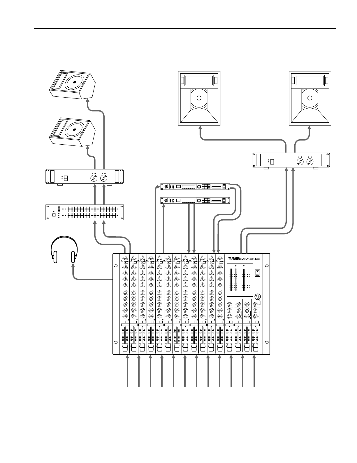
Application Example
Stage monitors
Power amp
Front of house
main speakers
Power amp
Effects processor
88
Graphic EQ
Headphone
MONITOR OUT
AUX
SEND1
88
AUX
SEND2
AUX
RTN2
AUX
RTN1
STEREO
OUT
MIXER
PHANTOM POWER
OUTPUT LEVEL
Mic and line inputs 1–12
7

Specifications
■ General Specifications
Maximum output level +24dB* (ST OUT L/R) @600Ω, 0,5% THD at 1kHz (Balanced)
+20dB* (AUX SEND 1–4) @600Ω, 0,5% THD at 1kHz (Unbalanced)
Total harmonic distortion 0.1% @+14dB* 20Hz–20kHz
(ST OUT L/R @600Ω, AUX SEND 1–4 @600Ω)
Frequency response 20Hz–20kHz +1dB, –2dB @+4dB* (MIC *IN=GAIN MIN)
(ST OUT L/R @600Ω, AUX SEND 1–4 @600Ω)
Hum and noise –127dB* Equivalent input noise
(Average, Rs=150Ω) –95dB* Residual output noise (ST OUT L/R @600Ω, AUX SEND 1–4 @600Ω)
(Measured With DIN AUDIO)
–78dB*(ST OUT L/R) Master fader: nominal
All channel fader: minimum
–63dB*(67dB S/N)(ST OUT L/R) Master fader: nominal
One channel fader: nominal
–78dB*(AUX SEND 1–4) Master level control: nominal
All channel AUX level control: minimum
–63dB*(67dB S/N)(AUX SEND 1–4) Master level control: nominal
One channel fader:
One channel AUX control: nominal
Maximum voltage gain 84dB MIC IN → ST OUT
50dB LINE IN → ST OUT
86dB MIC IN → AUX SEND1, 2
80dB MIC IN → AUX SEND3, 4
90dB MIC IN → MONITOR OUT
30dB AUX RETURN → ST OUT
Crosstalk –70dB adjacent input channels
–60dB input to output (except between ST L and R)
–55dB input to output (between ST L and R)
Gain control (MIC IN) 44dB variable range
Gain control (LINE IN) 36dB variable range
Input channel equalization HIGH ±12dB 12kHz shelving (max. ±15dB)
HI-MID ±12dB 3kHz peaking
LO-MID ±12dB 300Hz peaking
LOW ±12dB 80Hz shelving (max. ±15dB)
LED meters 0dB=+4dB* Output level
Channel PEAK indicators Red LED on each channel lights when pre-EQ, post-EQ, or post-fader signal reaches
3dB below clip level.
Phantom power +48V, DC
Power requirements US & Canadian Models: AC 120V, 60Hz
General Model: AC 230V, 50Hz
British Model: AC 240V, 50Hz
Power consumption US & Canadian Models: 45W
General Model: 55W
British Model: 55W
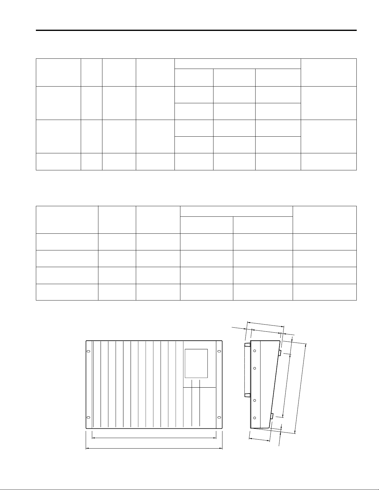
Dimensions (W × H × D) 483 × 130.2 × 320.6 mm (19" × 5.1" × 12.6")
Weight 8.5kg
* 0dB=0.775Vrms.
8
■ Input Specifications
Input level
Input
Gain Input Nominal
Trim impedance impedance
Sensitivity Nominal level
Maximum nonclipping level
Connector
type
MAX 4kΩ 50–600Ω –80dB –60dB –40dB XLR-3-31 type
MIC IN microphone (77.5µV) (775µV) (7.75mV) Balanced
(1–12) MIN –36dB –16dB +4dB
(12.3mV) (123mV) (1.23V)
MAX 10kΩ 600Ω line –46dB –26dB –6dB Phone jack
LINE IN (3.88mV) (38.8mV) (388mV) Unbalanced
(1–12) MIN –10dB +10dB +20dB
(245mV) (2.45V) (7.75V)
AUX RETURN 10kΩ 600Ω line –26dB –10dB
(1–4) (38.8mV) (245mV)
—
Stereo phone jack
0dB=0.775Vrms.
■ Output Specifications
Outpu
t
Output Nominal
impedance impedance Nominal level
ST OUT (L/R) 150Ω 600Ω Lines +4dB (1.23V) +24dB (12.3V)
AUX SEND (1–4) 75Ω 600Ω Lines +4dB (1.23V) +19dB (6.91V)
MONITOR OUT (L/R) 75Ω 600Ω Lines +4dB (1.23V) +19dB (6.91V)
HEAD PHONE 100Ω 40Ω Phones 3mW 120mW
Output level
Maximum nonclipping level
Connector type
XLR-3-32 type
(Balanced)
Phone jack
(Unbalanced)
Phone jack
(Unbalanced)
Stereo phone jack
(Unbalanced)
0dB=0.775Vrms.
■ Dimensions
Specifications and appearance subject to change without notice.
440
W:483
18.5
H
73.5
:
130.2
104.2
8.2
7.5
43.3
226
D: 320.6
Units: mm
9
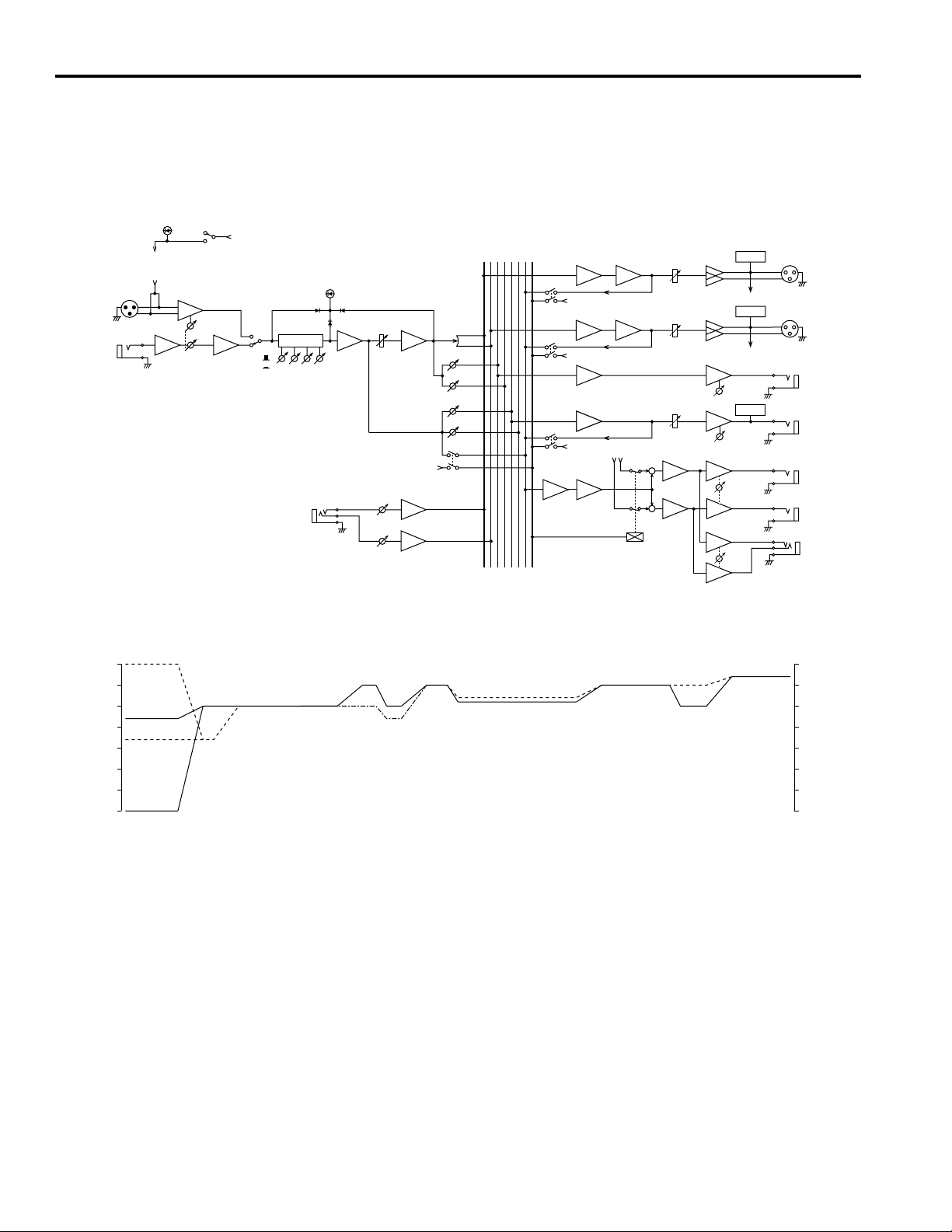
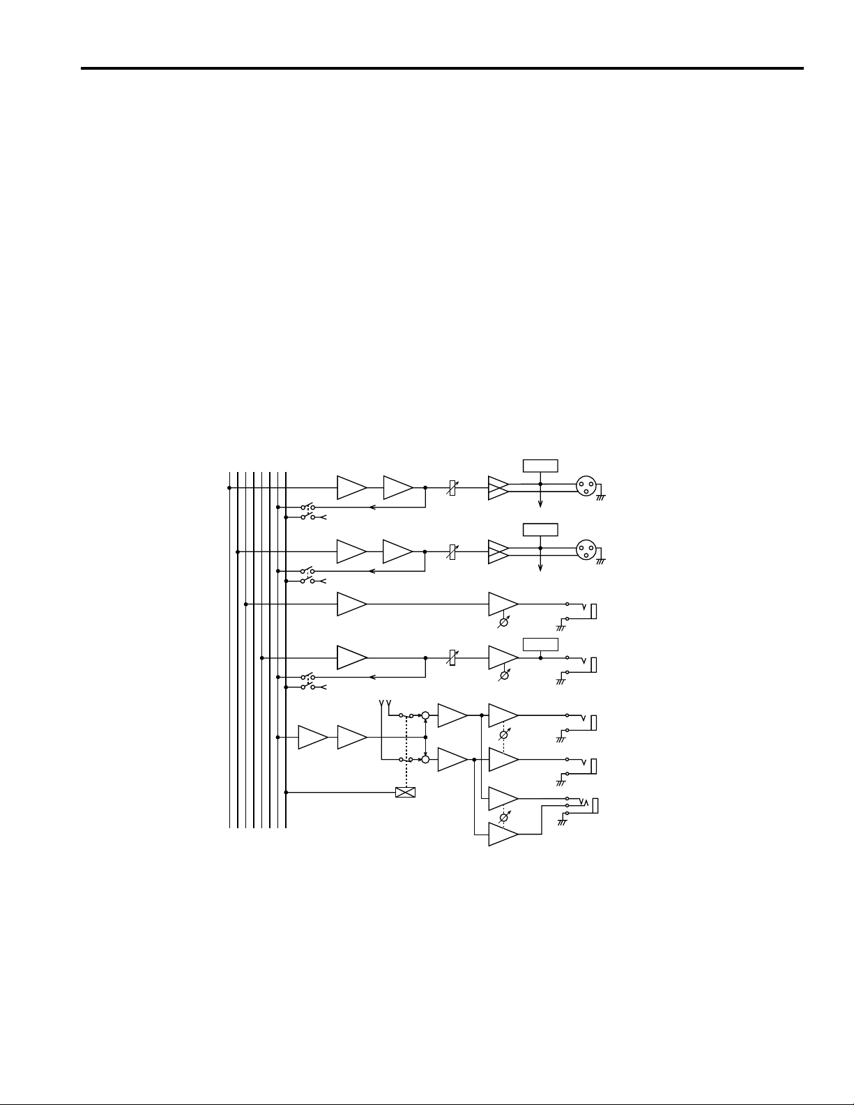
■ Block and Level Diagrams
PHANTOM
MIC IN
1-12
LINE IN
1-12
(MIC IN)
(PHANTOM)
HA
OFF
ON
PHANTOM
HA
GAIN
(+48V)
PEAK
BA
LINE
MIC
LOW
HIGH
HI-MID
LO-MID
ST AUX RTN
1〜 4 –10dB
AUX
STEREO
PFL4321RL
PFL CTRL
INVSUM
(+V)
PFL
BA
BAEQ
PAN
AUX 1
AUX 2
AUX 3
AUX 4
(+V)
PFL
INV
L
INV
R
PFL
PFL
SUM
INVSUM
(+V)
SUM INV
AUX SEND 1
SUM
(+V)
(ST OUT)
+
SUM
INV
+
SUM
INV
INV
INV
INV
INV
METER
(MONITOR)
METER
(MONITOR)
METER
MONITOR
LEVEL
L
STEREO OUT
+4dB
R
AUX SEND
1,2 +4dB
AUX SEND
3,4 +4dB
L
MONITOR
OUT +4dB
R
PHONES
(dB) (dB)
LINE(Min)
+10
–10
–20
–30
–40
–50
–60
0
MIC(Min)
LINE(Max)
MIC(Max)
AUX RETURN
AUX
STEREO
ST OUT
AUX SEND
MONITOR
+10
0
–10
–20
–30
–40
–50
–60
10

MELANGEUR
MANUEL D’INSTRUCTIONS
Français

Introduction
Félicitations! Vous voilà maintenant le fier détenteur d’une melangeur MM1242 de Yamaha.
C’est un produit de grande qualité qui allie facilité d’emploi, fonctionnalité et convivialité.
Ses performances sont exceptionnelles dans un grand nombre de domaines. Quant à sa
sonorité, seule toute l’expérience de Yamaha pouvait l’obtenir. Veuillez lire ce manuel
attentivement afin de pouvoir tirer le meilleur parti des nombreuses caractéristiques et
fonctions de cette console de mixage.
Caractéristiques
● Douze canaux d’entrée et sortie stéréo mix
● Fonction PFL (Pre Fader Listen/écoute avant curseur): elle vous permet de contrôler n’im-
porte quel canal d’entrée ainsi que les sorties ST L, R, AUX 3, 4 via moniteur ou casque.
● Tous les canaux d’entrée acceptent une entrée micro ou une entrée ligne ce qui facilite con-
sidérablement les connexions.
● L’alimentation fantôme vous permet de brancher des microphones à condensation.
● Quatre connecteurs AUX SEND et quatre connecteurs ST AUX RTN vous permettent de
brancher jusqu’à quatre processeurs d’effets externes.
Table des matières
Précautions ............................................................................ 1
Commandes du panneau avant .............................................. 2
Canal d’entrée ..................................................................2
Section Master .................................................................4
Panneau arrière ................................................................ 6
Exemple d’utilisation............................................................. 7
Caractéristiques .....................................................................8
Caractéristiques générales................................................ 8
Caractéristiques d’entrée.................................................. 9
Caractéristiques de sortie .................................................9
Dimensions ......................................................................9
Schémas de connexions et de niveaux ........................... 10

Précautions
1. Emplacement
Ne placez pas l’appareil dans un endroit où il risque d’être
exposé à des températures élevées ou une forte humidité
(évitez la proximité de radiateurs, poêles, etc). Evitez également les endroits poussiéreux ou soumis à des vibrations
qui peuvent être à l’origine de dommages mécaniques
ainsi que les endroits sujets à des champs magnétiques
importants, tels que la proximité de matériel de transmission.
2. Ventilation
L’appareil est pourvu de fentes d’aération sur les panneaux latéraux et inférieur. Ne bloquez jamais ces fentes.
3. Evitez tout choc
Un choc relativement important peut endommager l’appareil. Maniez-le donc avec soin.
4. N’ouvrez pas le boîtier et n’essayez pas d’effectuer des
réparations vous-même
Cet appareil ne contient pas d’élément pouvant être réparé
par l’utilisateur. Veuillez donc confier toute réparation à
un technicien Yamaha qualifié. Toute tentative d’ouverture du boîtier et de manipulation des circuits internes se
soldera par la perte du bénéfice de la garantie.
5. Coupez toujours l’alimentation avant de procéder à
des branchements
N’oubliez jamais de mettre les appareils hors tension
avant de brancher ou de débrancher des câbles afin de ne
pas endommager l’appareil lui-même ainsi que le matériel
qui y est branché.
6. Manipulez les câbles avec soin
Pour brancher et débrancher des câbles (y compris le câble
d’alimentation), prenez-le toujours par la prise et non par
le câble.
7. Nettoyez avec un chiffon doux et sec
N’utilisez jamais de solvants, tels que du benzène ou un
diluant pour nettoyer l’appareil. Prenez les poussières
avec un chiffon doux et sec.
8. Utilisez toujours une source d’alimentation adéquate
Assurez-vous que la tension spécifiée sur l’arrière de l’appareil correspond bien à celle de votre secteur et que les
prises utilisées peuvent assurer le courant nécessaire pour
faire fonctionner tout votre système.
1
 Loading...