

Page 1
1
Table of Contents
What is mLAN Mixer? .......... 2
Starting mLAN Mixer........... 2
Windows98/95 environment. 2
Macintosh environment ........ 2
Top Panel Screen ................. 3
Menu Bar.............................. 4
File menu .............................. 4
View menu............................ 4
Option .................................. 4
Help menu ............................ 5
Basic Controls....................... 6
Control knobs ....................... 6
Numeric field box ................. 6
Input Channel Settings
(Input Section) ..................7
Master Track Settings
(Output Section) ............... 9
• The software and this owner’s manual are exclusive copyrights of Yamaha Corporation.
• Copying of the software or reproduction of this manual in whole or in part by any means is
expressly forbidden without the written consent of the manufacturer.
• Yamaha makes no representations or warranties with regard to the use of the software and documentation and cannot be held responsible for the results of the use of this manual and the software.
• Copying of the commercially available music sequence data and/or digital audio files is strictly
prohibited except for your personal use.
• The company names and product names in this Owner’s Manual are the trademarks or registered trademarks of their respective companies.
• The screen displays as illustrated in this Owner’s Manual are for instructional purposes, and
may appear somewhat different from the screens which appear on your computer.
Channel Tab Window.........10
EQ (Equalizer)...................... 11
Dynamics ............................11
Delay...................................12
Effect Tab Screen................13
System Tab Screen .............14
mLAN8P.............................. 14
mLAN8E .............................. 16
Block Diagram (Audio).......17
mLAN8P.............................. 17
mLAN8E .............................. 18
Data List..............................19
Effect Type .......................... 19
Effects Parameters................ 20
Dynamics ............................29
Dynamics Library................. 34
EQ Library ........................... 35
This owner’s manual assumes that you are already familiar with basic Windows/Macintosh operation. If you are not, please refer to the owner’s manual which came with
your Windows/Mac OS software before using mLAN Mixer.
For information about hardware requirements, the interconnection of devices and
the installation of the mLAN Mixer software, refer to the separate “ Installation
Guide” as well as the owner’s manual for the respective mLAN device.
This owner’s manual is applicable to the mLAN Mixer for both Windows and Macintosh. The screen illustrations are mainly taken from the mLAN Mixer for Macintosh.
©2000 Y amaha Corporation
Page 2
What is mLAN Mixer?
mLAN Mixer is a software application that enables you to control the mixer functions of the mLAN8P/
mLAN8E from the computer as if you were controlling a normal mixing console. mLAN Mixer offers
independent EQ and dynamics settings for each channel, making it possible to perform detailed mixing
operation.
Starting mLAN Mixer
After installing mLAN Mixer and making the necessary connections, follow the steps below to start the
software.
Use mLAN Patchbay to set up the COM port for Windows.
Windows98/95 environment
In Windows98/95, select [Start | Program (P) | YAMAHA mLAN Mixer], then select “mLAN Mixer.”
Macintosh environment
Open the “YAMAHA mLAN Mixer” folder on the computer and double-click the “mLAN Mixer” icon.
2
Page 3
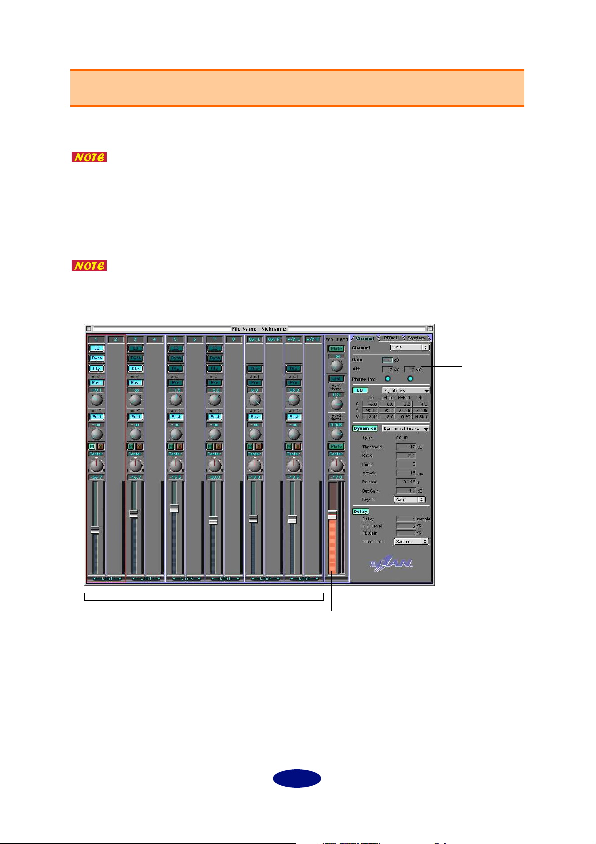
Top Panel Screen
The following screen appears when you start mLAN Mixer.
If there are multiple mLAN8P/mLAN8Es connected to the bus (system) of a Macintosh computer, a window appears, prompting you to select the device you wish to
control with the mLAN Mixer. You can select multiple devices to control simultaneously from the mLAN Mixer. If you are using a PC that runs Windows98/95, an
mLAN8P/mLAN8E connected serially to the computer will be automatically
selected.
The mLAN8P controlling screen and the mLAN8E controlling screen are slightly different. This manual references the mLAN8P controlling screen. However, functions
that differ are also explained.
input channels (input section)
parameters
master track (output section)
3
Page 4
Menu Bar
File menu
New: ......................... Creates a new Mixer file.
Open: ....................... Opens an existing Mixer file.
Save: ......................... Overwrites an existing file with the currently-edited Mixer file.
Save As: .................... Saves the currently-edited Mixer file with a different name.
Quit: ......................... Closes mLAN Mixer.
“ Save” and “ Save As” do not save the Level, Meter Source, Peak Hold, Fall Time,
and Word Clock settings.
The edited settings for the mLAN mixer will be lost when the power to the
mLAN8P/mLAN8E is turned off. (This does not apply to the parameters accessible
from the control panel of the unit.) Be sure to store the necessary settings using the
File menu.
View menu
Hide/Show Parameter: ............... Displays or hides various parameters in the tab screens.
Option
Init Channel (Initialize Channel): ......Opens the Init Channel dialog that is used to initial-
ize the settings for selected channels or all channels.
Preference (Windows only): ................Opens the Preference dialog that is used to customize
the menu shortcut keys.
4
Page 5
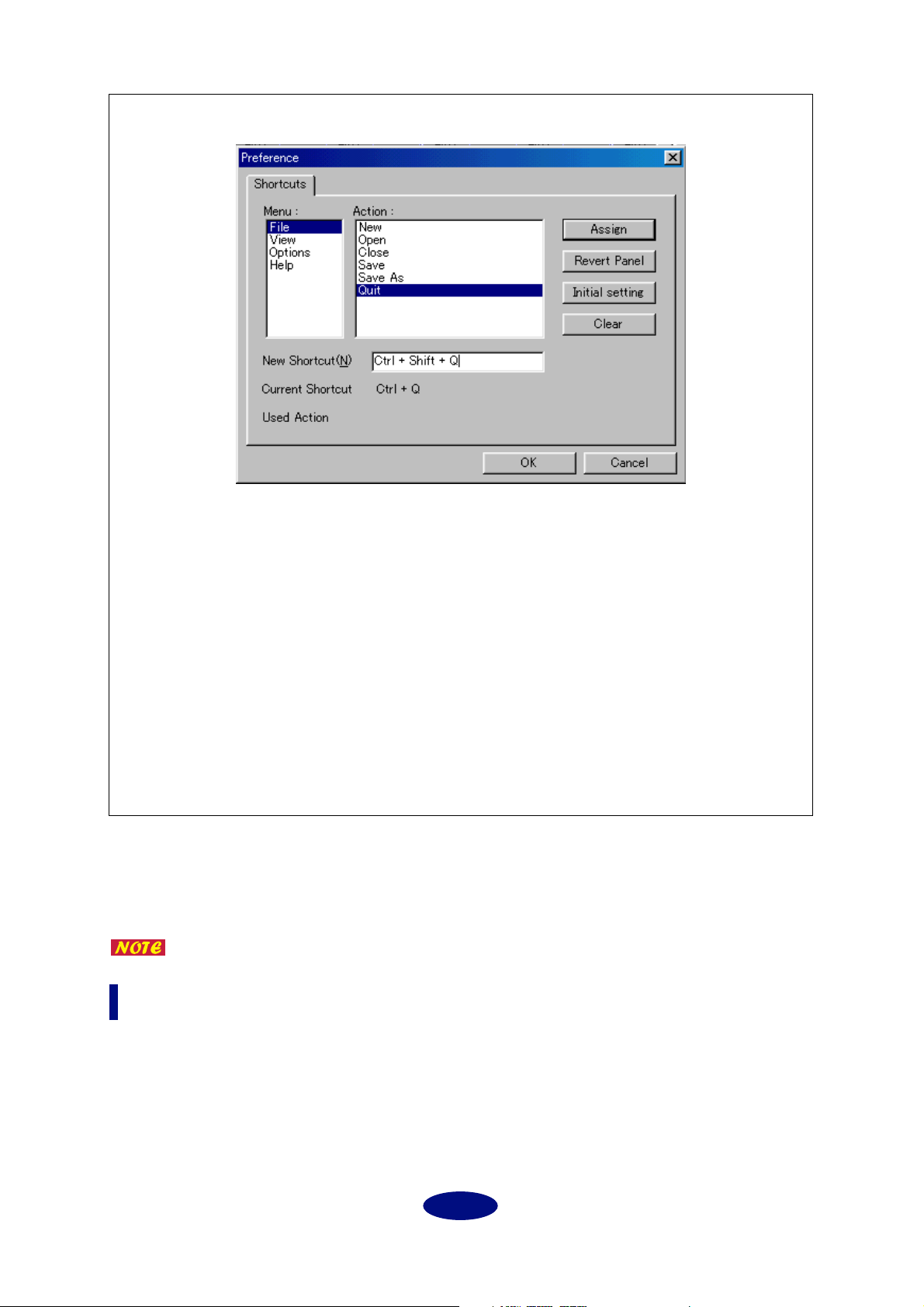
Preference dialog (Setting the shortcuts) (Windows only)
Shortcuts
1. Select a menu and action from the Menu and Action columns for which you wish to set
a shortcut. In the example above, [New] in the File menu is selected.
2. Click [New Shortcuts] and press the desired shortcut key. In the example above, the [Q]
key is pressed while the [Ctrl] and [Shift] keys are held down. If the shortcut key has
already been assigned to another “Action,” the “Used Action” column displays the name
of the “Action.”
3. Click [Assign]. The “Current Shortcut” column displays the selected shortcut.
4. Press the [OK] button to confirm the selected shortcut setting. If you do not wish to
change the setting, click [Cancel].
Revert Panel: ......... Returns to the previous setting.
Initial setting: ........ The shortcut is set to the [Ctrl] key plus the first letter of the
selected Action.
Clear: ...................... Clears the setting.
Direct Mode: ........... You can temporarily place mLAN Mixer in Direct mode while you are
controlling the mLAN8E. This function is not available with the
mLAN8P.
Refer to the Owner’s manual for the mLAN8E for more information on Direct mode.
Help menu
About mLAN Mixer (A): ............ Displays the version information for the mLAN Mixer
(Windows).
5
Page 6
Basic Controls
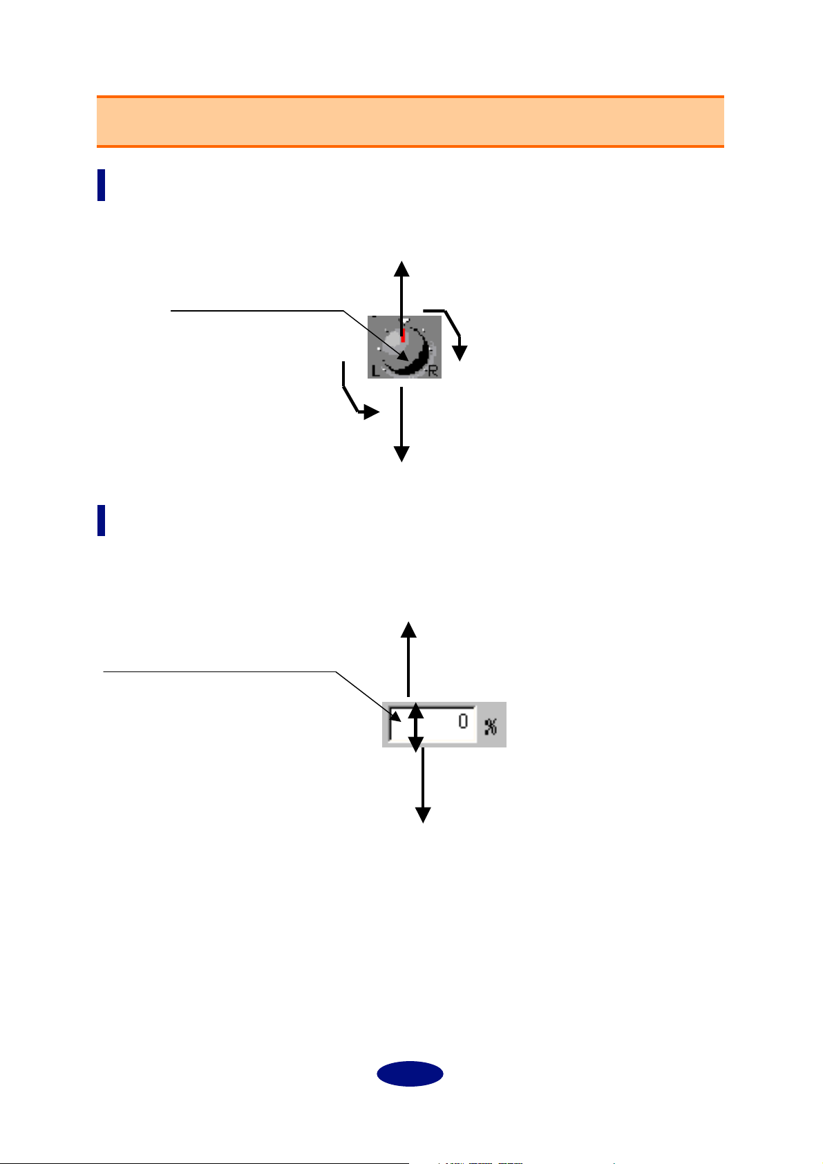
Control knobs
To rotate a control knob clockwise, click-and-hold the mouse on the knob while dragging upward. Drag
down to rotate the knob counter-clockwise.
Click-and-hold the mouse
on a control knob.
Move the mouse upward to rotate
the knob clockwise.
Move the mouse downward to rotate
the knob counter-clockwise.
Numeric field box
Click-and-hold the mouse and drag upward in a number box to continuously increment the value.
Drag the mouse downward to decrement the value.
You can also enter the value directly by clicking (double-clicking) the box.
Click-and-hold down the mouse button
in the box.
(The pointer changes to an arrow.)
Drag the mouse downward to continuously decrement the value.
Drag the mouse upward to continuously increment the value.
6
Page 7
A
B
C
D
E
F
G
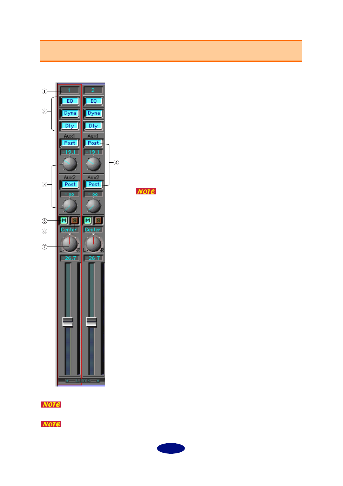
Input Channel Settings (Input Section)
You can adjust the input signal level and effect on/off for each channel.
Channel number
Channels 1-8 are used for input signals via mLAN. Channels 9 and 10 are
used for Digital input signals, and channels 11 and 12 are used for A/D
input signals.
EQ/Dyna (Dynamics)/Dly (Delay) button
These buttons are used to switch EQ, Dynamics, and Delay on and off for
each channel. The settings are linked with the buttons in the Channel tab.
Aux 1/2 send knobs
These knobs are used to adjust the level of each channel signal sent to
AUX 1/2.
Use these knobs when you are sending signals to an external effect processor or when you are monitoring signals with a balance that is different
from the stereo output balance.
If you are using the mLAN8P: Signals sent to AUX2 are also sent to the
internal multi-effect processor.
When AUX Layer is turned on, you can set AUX 3-6
parameters (mLAN8E).
Pre/Post buttons
These buttons enable you to select a pre-fader (Pre) signal or a post-fader
(Post) signal as the AUX send signal. With the “Pre” setting, a signal is
sent to the AUX bus before it reaches the channel fader; thus the signal is
not affected by the channel fader setting. With the “Post” setting, a signal
is sent to the AUX bus after it passes through the channel fader; thus the
signal is affected by the channel fader.
M (Mute) button
Press this button to mute the corresponding channel signal.
S (Solo) button
Press this button to monitor the corresponding channel signal.
Press this button while holding down the Shift key to monitor multiple
channel signals.
Panpot knob
This knob enables you to set the stereo position of the corresponding
channel. If the channel’s Link switch is set to “ON,” the knob adjusts the
signal balance.
You can set the attenuation and phase independently for each channel, even when
the Link switch is turned on.
When adjacent channels are linked, the panpot knob enables you to adjust the level
balance between the odd and even channels.
7
Page 8
H
I
J
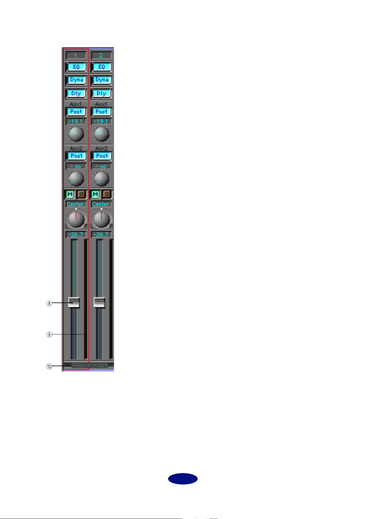
Channel fader
The channel fader enables you to adjust the channel level. Click and hold
down the mouse button on the fader and slide the mouse up and down,
or click a desired point on the fader to move the fader to that point.
Channel level meter
The channel level meter is displayed on the right side of the channel
fader. The channel meter source is always the signal just after the gain, so
the channel level meter displays the level of the input signal and is not
affected by the EQ, Dynamics or the fader.
Link (Link switch)
When this switch is turned on, adjacent channels (1 and 2, 3 and 4, etc.)
are linked to each other for stereo operation.
8
Page 9
A
B
C
D
E
F
G
H
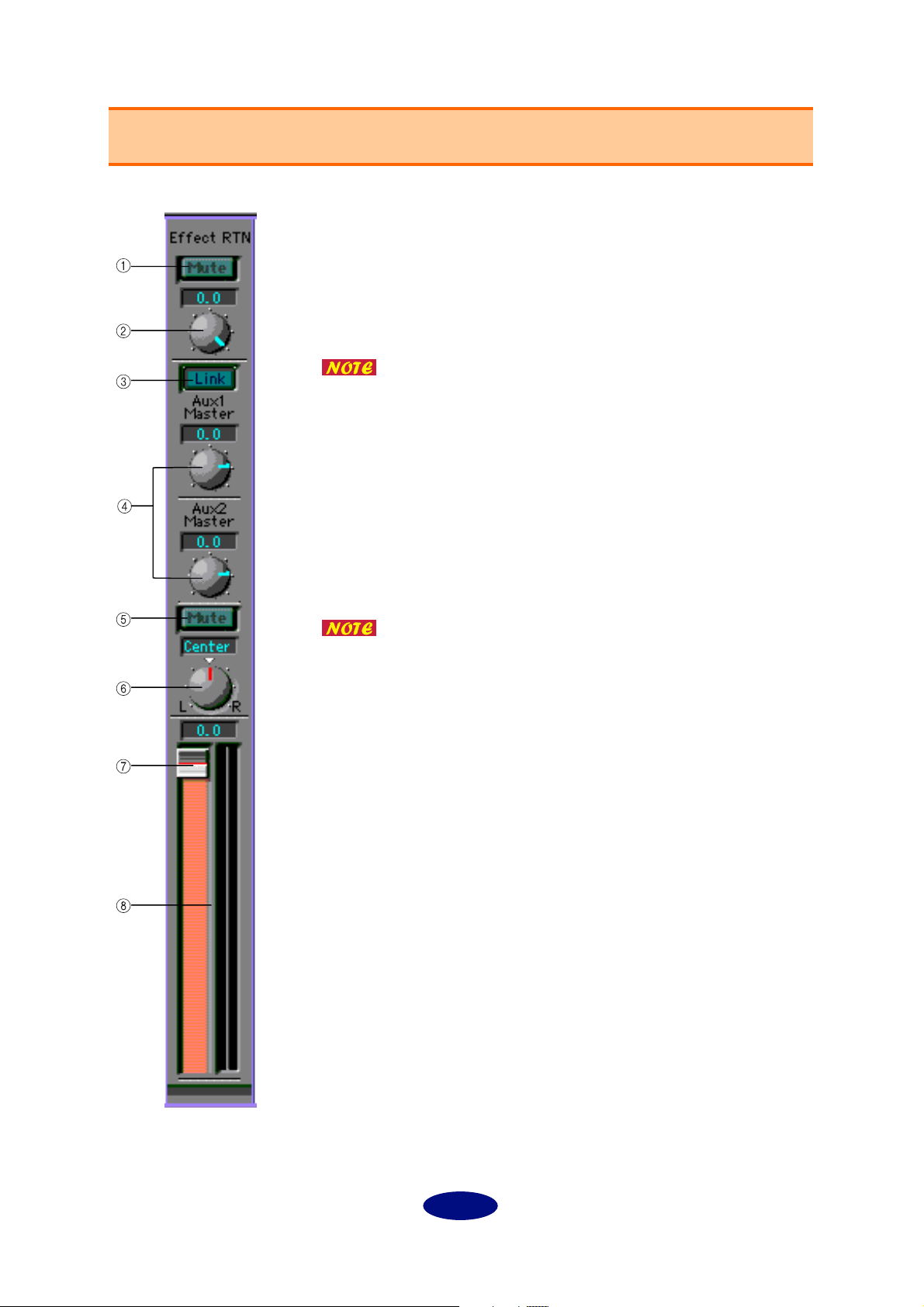
Master Track Settings (Output Section)
In this section, you can set the stereo out fader, AUX master level, and effect return level.
Mute button (mLAN8P only)
Press this button to mute the return signal from the internal multi-effect
processor.
Effect RTN (mLAN8P only)
This knob adjusts the amount of signal processed by the effect processor
and routed to Stereo Out.
The mLAN8E features an AUX Layer button instead of this
button. When you turn this button on, you can set AUX 3-6
parameters for both input channels and the master track.
Link button
Set this button to ON to link the AUX 1 and 2 settings. When they are
linked, the panpot setting of the corresponding input channel is used.
This is useful when you wish to use AUX 1 and 2 as individual stereo
outputs.
AUX 1/2 Master
These are used to adjust the level of the AUX 1 and 2 return signals.
When AUX Layer is turned on, you can set AUX 3-6 parameters (mLAN8E).
Mute button
Press this button to mute the stereo mix output.
Balance
This knob adjusts the left and right balance of the stereo mix output.
Stereo mix fader
This fader adjusts the level of the stereo mix signal. Click-and-hold the
mouse on the fader and slide the mouse up and down, or click the
desired point on the fader to move the fader to that point.
Level meter
The level meter is displayed on the right side of the fader. The meter
source signal is specified by the Mix Meter Source parameter.
9
Page 10
A
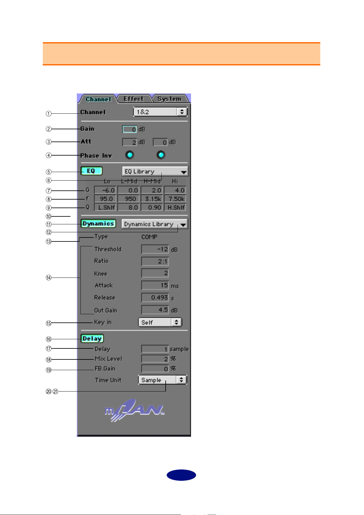
Channel Tab Window
mLAN Mixer offers the parameters independently for each channel, making detailed mixing operations
possible.
Channel (Target Channel)
Select the channel you wish to set here.
Click the desired input channel module
to display the corresponding channel
number here automatically.
Gain
This parameter enables you to adjust
the input level in steps of 6dB.
Internally, mLAN Mixer performs a Bit
Shift process.
Settings: –12 – +24dB
B
C
D
Att (Attenuator)
This parameter enables you to set the
input level in steps of 1dB. In this way,
you can fine tune the Gain value.
Settings: –96–+24dB
Phase Inv (Inverted)
Click the check box to reverse the phase
of the input signal.
10
Page 11
E
F
G
H
I
J
K
L
EQ (Equalizer)
EQ button
This button turns the selected channel EQ on or off. It is linked to each channel’s EQ button.
EQ Library
This parameter enables you to select a preset EQ type.
G (dB)
This parameter sets the amount of boost (+) or cut (–) of the signal at the specified frequency (F (Hz)).
Settings: –18–+18dB (in steps of 0.5dB), ON/OFF (only when [HPF] or [LPF] is selected for the
“Type” parameter with the Macintosh version.)
F (Hz)
This parameter sets the equalizing frequency.
LO: ................... 21 (Hz) – 20.0 k(Hz)
L-MID: ............ 21 (Hz) – 20.0 k(Hz)
H-MID: ........... 21 (Hz) – 20.0 k(Hz)
HI:
.................... 21 (Hz) – 20.0 k(Hz)
Q
This parameter sets the frequency range for boost and cut. The higher the value is, the smoother the
changes in the specified frequency range. With the Macintosh version, use this parameter to make
the setting for “Type.”
Settings: 10.0–0.10
Type (Windows only)
This parameter enables you to select a type of EQ.
With the Macintosh version, set the Q value (
select a Type.
[LO]
PEAK (peaking):
LSLV (low-shelving): A shelving-type equalizer that boosts and cuts the signal in the low range.
LPF (low pass filter): A filter that cuts the frequency range above the threshold specified by the “F
[HI]
PEAK (peaking):
HSLV (high-shelving): A shelving-type equalizer that boosts and cuts the signal in the high range.
HPF (high pass filter): A filter that cuts the frequency range below the threshold specified by the “F
mLAN Mixer uses a 4-band full parametric equalizer. Basically, a parametric equalizer changes a tone by boosting (+) or cutting (–) the signal at the specified frequency. Boosting emphasizes the corresponding frequency range, and cutting
attenuates the range. mLAN Mixer offers many presets suitable for various applications. Select one that suits your application, and fine tune it for quick operation.
A normal parametric equalizer
(frequency)” parameter.
A normal parametric equalizer
(frequency)” parameter.
) to the maximum or minimum to
9
Dynamics
Dynamics button
This button turns the dynamics processor of the selected channel on or off. This button is linked
with each channel’s Dynamics button.
Dyna (Dynamics) Library
Select the desired Dynamics type (page 34).
11
Page 12

M Ty p e
This field displays the type of dynamics selected in the Dyna Library field.
N Dynamics Parameters
These parameters are for the dynamics of the type indicated in the “Type” field (M). For more information, refer to Dynamics in the Data List on page 29.
O Key in (Key in Source)
You can set the ducking effect. Ducking is used for voice-over applications in which the background
music level is reduced automatically when the announcer speaks. For dynamics processing, match
the Key in the source parameter of the Target Channel (music channel) with that of the voice channel.
The input channel processors can be self-triggered (triggered by the signal to be processed), or they
can be triggered by a signal from another channel.
Dynamics processors are generally used to correct or control signal levels (like a
compressor) and psycho-acoustically extend the sustain. mLAN Mixer provides not
only a compressor but gates, limiters, and other types of processors for various
occasions.
mLAN Mixer offers many presets suitable for various applications. Select one that
suits your application, and fine tune it for quick operation.
Delay
This function is not available on the mLAN8E.
P Delay button
This button turns the selected channel Delay on or off. It is liked to each channel’s Dly (Delay) button.
Q Delay/Time (Delay Time)
This parameter sets the delay time.
Settings (sample): 1–9600 samples
Settings (millisecond): 0.023–217.687ms (44.1kHz), 0.021–200.00ms (48kHz)
R Mix Level
This parameter sets the mix balance between the dry sound and the delay sound.
With a setting of “0,” the ratio of dry signal to delay signal is 1:0. With a setting of “+50,” the ratio is
1:1. With a setting of “+100,” the ratio is 0:1. If the value is negative, the phase of the delay signal is
reversed.
FB.Gain/FB. Level
S
This parameter sets the delay feedback amount.
This level is the amount of the delay signal fed back to the delay effect. With a setting of “0,” there is
no feedback. With a setting of “+99,” the feedback is at maximum. If the value is negative, the phase
of the delay signal is reversed.
Sample
T
Select this option to display the delay time in sample units.
With 44.1kHz, one sample corresponds to 1/44,100 seconds. With 48kHz, one sample corresponds
to 1/48,000 seconds.
MS (millisecond)
U
Select this option to display the delay time in ms (milliseconds).
Both options are based on either 1/44,100 seconds or 1/48,000 seconds, and feature
the same upper limit value. Select the desired option depending on your application.
12
Page 13

Effect Tab Screen
You can set the internal effect parameters on this screen. (mLAN8P only)
A Effect Mono Mix (Mono)
This parameter enables you to mix the L/R effect
return signals into a monaural signal.
Effect Pan (Balance/Return Pan)
B
This parameter sets the L/R balance of the effect
return signals.
C Ty p e
This parameter enables you to select the desired
effect type (page 19).
D Use these parameters to set up the effect speci-
fied by the Type parameter. The displayed
parameters differ depending on the selected
(page 20).
effect
mLAN Mixer offers many presets suitable for
various applications. Select one best suits your
application, and fine tune it for quick operation.
13
Page 14

System Tab Screen
You can make settings related to the mLAN8P/mLAN8E on this screen.
mLAN8P
A Mixer Type
You can assign EQ and Dyna for up to eight channels. The assignments for channels 1-4 are fixed.
You can assign EQ and Dyna for the other four
channels here.
1: EQ and Dyna are assigned to channels 5-8.
2: EQ and Dyna are assigned to channels 5-6 and
Digital in.
3: EQ and Dyna are assigned to channels 5-6 and
A/D in.
4: EQ and Dyna are assigned to Digital in and A/
D in.
Mix Meter Source (Level Meter Source)
B
This parameter enables you to select a signal to
display on the master track level meter.
Stereo Mix: Displays the stereo output signal.
Effect Return: Displays the effect return signal.
AUX1/2: Displays the AUX1/2 master output sig-
nal.
Meter Setting
C
This parameter enables you to select the type of
level meter display.
Peak Hold ON: The meter holds the peak level
until you turn off “Peak Hold.”
Peak Hold OFF: The meter does not hold the peak
level.
Fall Time: This parameter sets the speed of the
meter’s response to the decaying sound.
Normal: Normal response speed
Fast: The meter responds quickly to and reflects
the attenuating sound. This setting clarifies the
attack level on the meter.
OFF: The level meter is not displayed.
Digital Input
D
This parameter enables you to select Optical or
Coaxial for the input signal at the Digital In connector on the mLAN8P.
Digital Output
E
This parameter specifies the signal routed to the
Digital Out connector on the rear panel of the
mLAN8P.
Settings: Stereo Mix, AUX1/2, Coaxial/Optical In,
A/D In
14
Page 15

F Analog Output
This parameter specifies the signal routed to the D/A out connector on the rear panel.
Settings: Stereo Mix, AUX1/2, Coaxial/Optical (depending on the Digital Input settings) In, A/D In
Word Clo ck
G
This parameter specifies the word clock for the mLAN8P.
Settings: Internal44.1k, Internal48k, Coaxial/Optical (depending on the Digital Input settings),
mLAN (follows the unit’s or mLAN Patchbay’s setting.)
Device Fs
H
This field displays the actual sampling frequency.
The signal specified by the Analog Output source parameter is also output to connected headphones.
15
Page 16

mLAN8E
A Mixer Type
You can assign EQ and Dyna to up to eight channels.
1: EQ and Dyna are assigned to channels 1-8.
2: EQ and Dyna are assigned to channels 1-6 and
9-10.
3: EQ and Dyna are assigned to channels 1-4 and
9-12.
4: EQ and Dyna are assigned to channels 9-16.
Mix Meter Source (Level Meter Source)
B
This parameter enables you to select a signal to
display on the master track level meter.
Stereo Mix: Displays the stereo output signal.
AUX1/2: Displays the AUX1/2 signal.
AUX3/4: Displays the AUX1/2 signal.
AUX5/6: Displays the AUX1/2 signal.
Meter Setting:
C
This parameter enables you to select the type of
level meter display.
Peak Hold ON: The meter holds the peak level
until you turn off “Peak Hold.”
Peak Hold OFF: The meter does not hold the peak
level.
Fall Time: This parameter sets the speed of the
meter’s response to the decaying sound.
Normal: Normal response speed
Fast: The meter responds quickly to and reflects
the attenuating sound. This setting clarifies the
attack level on the meter.
OFF: The level meter is not displayed.
Word Clo ck
D
This parameter specifies the word clock for the
mLAN8E.
Settings: Internal44.1k, mLAN (follows the unit’s
or mLAN Patchbay’s setting.)
Device Fs
E
This field displays the actual sampling frequency.
The signal specified by the Analog Output source parameter is also output to connected headphones.
16
Page 17

Block Diagram (Audio)
mLAN8P
mLAN Plug Name
Input 3
Input 8
1Input 1
2Input 2
mLAN
3
8
DIGITAL
INPUT
SELECT
SFC
DAC
LEVEL METER KEY IN
GAIN PHASE DELAY4 BAND EQ DYNAMICSATT
GAIN PHASE DELAY4 BAND EQ DYNAMICSATT
9
10
11
Same as above,
except that the 4-band EQ and Dynamics processor can be assigned to up to eight channels.
KEY IN
AUX2 MIX R
AUX1 MIX L
LEVEL
ON
PRE/POST
PANPOT
SEND
DIGITAL OUTPUT
SELECT
AUX1
AUX2
MIX L
MIX R
ANALOG OUTPUT
SELECT
AUX1
AUX2
MIX L
MIX R
DAC
DAC
OUT1
OUT2
PHONES
VOLUME
PHONES
L/R
INPUT
VOLUME
DAC
12
LEVEL METER
EFFECT
mLAN Plug Name
AUX1
AUX2
St Mix L
St Mix R
Dig In L
Dig In R
A/D In L
A/D In R
LEVEL METER
AUX1
AUX2
MIX L
MIX R
17
Page 18

mLAN8E
mLAN
LEVEL METER KEY IN
LEVEL
1
2
3
8
9
16
GAIN PHASE 4 BAND EQ DYNAMICSATT
GAIN PHASE 4 BAND EQ DYNAMICSATT
KEY IN
Same as above,
except that the 4-band EQ and Dynamics processor can be assigned to up to eight channels.
ON
PRE/POST
PANPOT
SEND
AUX
12 4 63
5RL
MIX
LEVEL METER
AUX1
AUX2
18
mLAN
MIX L
MIX R
Page 19

Data List
Effect Type
Reverb-type Effects
# Type Description
01
Reverb Hall
02
Reverb Room
03
Reverb Stage
04
Reverb Plate
05
Early Ref.
06
Gate Reverb
07
Reverse Gate A reverse-playback type ER.
Reverb simulating a large space such
as a concert hall.
Reverb simulating the acoustics of a
smaller space (room) than REVERB
HALL.
Reverb designed with vocals in
mind.
Simulation of a metal-plate reverb
unit, producing a feeling of hardedged reverberation.
An effect which isolates only the
early refl ection (ER) component
from reverberation. A fl ashier effect
than reverb is produced.
A type of ER designed for use as
gated reverb.
Delays
# Type Description
08
Mono Delay
09
Stereo Delay
10
Mod.delay Mono delay with modulation.
11
Delay LCR Three-tap delay (L, C, R).
12
Echo
Mono delay with simple operation.
Use when you don' t need to use
complex parameter settings.
Stereo delay with independent left
and right.
Stereo delay with additional parameters for more detailed control. The
signal can be fed back from left to
right, and right to left.
Guitar Effects
# Type Description
23
Distortion Distortion
24
Amp Simulate Guitar Amp Simulator
Dynamic Effects
# Type Description
25
Dyna.Filter Dynamically controlled filter.
26
Dyna.Flange Dynamically controlled fl anger.
27
Dyna.Phaser Dynamically controlled phase shifter.
Modulation-type Effects
# Type Description
13
Chorus Three-phase stereo chorus.
14
Flange The well-known fl anging effect.
15
Symphonic
16
Phaser
17
Auto Pan
18
Tremolo Tremolo
19
Dual Pitch
20
Rotary Simulation of a rotary speaker.
21
Ring Mod.
22
Mod.Filter
A Yamaha proprietary effect that
produces a richer and more complex
modulation than chorus.
Stereo phaser with 2–16 stages of
phase shift.
An effect which cyclically moves the
sound between left and right.
Stereo pitch shift with left and right
pitches set independently.
An effect that modifies the pitch by
applying amplitude modulation to
the frequency of the input. Even the
modulation frequency can be controlled by modulation.
An effect which uses an LFO to modulate the frequency of the filter.
Combined Effects
# Type Description
28
Rev+Chorus Reverb and chorus in parallel
29
Rev->Chorus Reverb and chorus in series
30
Rev+Flange Reverb and fl anger in parallel
31
Rev->Flange Reverb and fl anger in series
32
Rev+Sympho. Reverb and symphonic in parallel
Rev->Sym-
33
pho.
34
Rev->Pan Reverb and auto-pan in parallel
35
Delay+ER. Delay and early refl ections in parallel
36
Delay->ER. Delay and early refl ections in series
37
Delay+Rev Delay and reverb in parallel
38
Delay->Rev Delay and reverb in series
39
Dist->Delay Distortion and delay in series
Reverb and symphonic in series
19
Page 20

Effects Parameters
REVERB HALL, REVERB ROOM, REVERB STAGE, REVERB PLATE
Parameter Range Description
REV TIME 0.3–99.9 s Reverb time
INI.DLY 0.0–500.0 ms Initial delay before reverb begins
HI.RATIO 0.1–1.0 High-frequency reverb time ratio
LO.RATIO 0.1–2.4 Low-frequency reverb time ratio
DIFF. 0–10 Reverb diffusion (left–right reverb spread)
DENSITY 0–100% Reverb density
E/R DLY 0.0–100.0 ms Delay between early refl ections and reverb
E/R BAL. 0–100% Balance of early refl ections and reverb (0% = ER, 100% = reverb)
HPF Thru, 21 Hz–8.0 kHz High-pass filter cutoff frequency
LPF 50 Hz–16.0 kHz, Thru Low-pass filter cutoff frequency
EARLY REF.
Parameter Range Description
TYPE
ROOMSIZE 0.1–20.0 Refl ection spacing
LIVENESS 0–10 Early refl ections decay characteristics (0 = dead, 10 = live)
INI.DLY 0.0–500.0 ms Initial delay before reverb begins
DIFF. 0–10 Reverb diffusion (left–right reverb spread)
DENSITY 0–100% Reverb density
ER NUM. 1–19 Number of early refl ections
FB GAIN –99 to +99% Feedback gain
HI.RATIO 0.1–1.0 High-frequency feedback ratio
HPF Thru, 21 Hz–8.0 kHz High-pass filter cutoff frequency
LPF 50 Hz–16.0 kHz, Thru Low-pass filter cutoff frequency
S-Hall, L-Hall, Random,
Revers, Plate, Spring
Type of early refl ection simulation
GATE REVERB, REVERSE GATE
Parameter Range Description
TYPE Type-A, Type-B Type of early refl ection simulation
ROOMSIZE 0.1–20.0 Refl ection spacing
LIVENESS 0–10 Early refl ections decay characteristics (0 = dead, 10 = live)
INI.DLY 0.0–500.0 ms Initial delay before reverb begins
DIFF. 0–10 Reverb diffusion (left–right reverb spread)
DENSITY 0–100% Reverb density
HI.RATIO 0.1–1.0 High-frequency feedback ratio
ER NUM. 1–19 Number of early refl ections
FB GAIN –99 to +99% Feedback gain
HPF Thru, 21 Hz–8.0 kHz High-pass filter cutoff frequency
LPF 50 Hz–16.0 kHz, Thru Low-pass filter cutoff frequency
MONO DELAY
Parameter Range Description
DELAY 0.0–2730.0 ms Delay time
FB.GAIN –99 to +99%
HI.RATIO 0.1–1.0 High-frequency feedback ratio
HPF Thru, 21 Hz–8.0 kHz High-pass filter cutoff frequency
LPF 50 Hz–16.0 kHz, Thru Low-pass filter cutoff frequency
Feedback gain (plus values for normal-phase feedback, minus values for
reverse-phase feedback)
20
Page 21

STEREO DELAY
Parameter Range Description
DELAY L 0.0–1350.0 ms Left channel delay time
FB.G L –99 to +99%
DELAY R 0.0–1350.0 ms Right channel delay time
FB.G R –99 to +99%
HI.RATIO 0.1–1.0 High-frequency feedback ratio
HPF Thru, 21 Hz–8.0 kHz High-pass filter cutoff frequency
LPF 50 Hz–16.0 kHz, Thru Low-pass filter cutoff frequency
Left channel feedback (plus values for normal-phase feedback, minus values for reverse-phase feedback)
Right channel feedback (plus values for normal-phase feedback, minus values for reverse-phase feedback)
MOD.DELAY
Parameter Range Description
DELAY 0.0–2725.0 ms Delay time
FB.GAIN –99 to +99%
FREQ. 0.05–40.00 Hz Modulation speed
DEPTH 0–100% Modulation depth
HI.RATIO 0.1–1.0 High-frequency feedback ratio
HPF Thru, 21 Hz–8.0 kHz High-pass filter cutoff frequency
LPF 50 Hz–16.0 kHz, Thru Low-pass filter cutoff frequency
Feedback gain (plus values for normal-phase feedback, minus values for
reverse-phase feedback)
DELAY LCR
Parameter Range Description
DELAY L 0.0–2730.0 ms Left channel delay time
LEVEL L –100 to +100% Left channel delay level
DELAY C 0.0–2730.0 ms Center channel delay time
LEVEL C –100 to +100% Center channel delay level
DELAY R 0.0–2730.0 ms Right channel delay time
LEVEL R –100 to +100% Right channel delay level
FB.DLY 0.0–2730.0 ms Feedback delay time
FB.GAIN –99 to +99%
HI.RATIO 0.1–1.0 High-frequency feedback ratio
HPF Thru, 21 Hz–8.0 kHz High-pass filter cutoff frequency
LPF 50 Hz–16.0 kHz, Thru Low-pass filter cutoff frequency
Feedback gain (plus values for normal-phase feedback, minus values for
reverse-phase feedback)
ECHO
Parameter Range Description
DELAY L 0.0–1350.0 ms Left channel delay time
FB.G L –99 to +99%
DELAY R 0.0–1350.0 ms Right channel delay time
FB.G R –99 to +99%
FB.D L 0.0–1350.0 ms Left channel feedback delay time
L->R FB.G –99 to +99%
FB.D R 0.0–1350.0 ms Right channel feedback delay time
R->L FB.G –99 to +99%
HI.RATIO 0.1–1.0 High-frequency feedback ratio
HPF Thru, 21 Hz–8.0 kHz High-pass filter cutoff frequency
LPF 50 Hz–16.0 kHz, Thru Low-pass filter cutoff frequency
Left channel feedback gain (plus values for normal-phase feedback, minus
values for reverse-phase feedback)
Right channel feedback gain (plus values for normal-phase feedback,
minus values for reverse-phase feedback)
Left to right channel feedback gain (plus values for normal-phase feedback,
minus values for reverse-phase feedback)
Right to left channel feedback gain (plus values for normal-phase feedback,
minus values for reverse-phase feedback)
21
Page 22

CHORUS
Parameter Range Description
FREQ. 0.05–40.00 Hz Modulation speed
DEPTH 0–100% Modulation depth
MOD.DLY 0.0–500.0 ms Modulation delay time
WAVE Sine, Tri Modulation waveform
FLANGE
Parameter Range Description
FREQ. 0.05–40.00 Hz Modulation speed
DEPTH 0–100% Modulation depth
MOD.DLY 0.0–500.0 ms Modulation delay time
FB.GAIN –99 to +99%
WAVE Sine, Tri Modulation waveform
Feedback gain (plus values for normal-phase feedback, minus values for
reverse-phase feedback)
SYMPHONIC
Parameter Range Description
FREQ. 0.05–40.00 Hz Modulation speed
DEPTH 0–100% Modulation depth
MOD.DLY 0.0–500.0 ms Modulation delay time
WAVE Sine, Tri Modulation waveform
PHASER
Parameter Range Description
FREQ. 0.05–40.00 Hz Modulation speed
DEPTH 0–100% Modulation depth
FB.GAIN –99 to +99%
OFFSET 0–100 Lowest phase-shifted frequency offset
STAGE 2, 4, 8, 10, 12, 14, 16 Number of phase shift stages
Feedback gain (plus values for normal-phase feedback, minus values for
reverse-phase feedback)
AUTOPAN
Parameter Range Description
FREQ. 0.05–40.00 Hz Modulation speed
DEPTH 0–100% Modulation depth
DIR.
WAVE Sine, Tri, Square Modulation waveform
a. L<->R, L— >R, L<— R, Turn L, Turn R
a
Panning direction
TREMOLO
Parameter Range Description
FREQ. 0.05–40.00 Hz Modulation speed
DEPTH 0–100% Modulation depth
WAVE Sine, Tri, Square Modulation waveform
22
Page 23

DUAL PITCH
Parameter Range Description
PITCH L –24 to +24 semitones Left channel pitch shift
FINE L –50 to +50 cents Left channel pitch shift fine
LEVEL L –100 to +100%
PITCH R –24 to +24 semitones Right channel pitch shift
FINE R –50 to +50 cents Right channel pitch shift fine
LEVEL R –100 to +100%
DELAY L 0.0–1000.0 ms Left channel delay time
FB.G L –99 to +99%
DELAY R 0.0–1000.0 ms Right channel delay time
FB.G R –99 to +99%
MODE 1–10 Pitch shift precision
Left channel level (plus values for normal phase, minus values for reverse
phase)
Right channel level (plus values for normal phase, minus values for reverse
phase)
Left channel feedback gain (plus values for normal-phase feedback, minus
values for reverse-phase feedback)
Right channel feedback gain (plus values for normal-phase feedback,
minus values for reverse-phase feedback)
ROTARY
Parameter Range Description
ROTATE STOP, START Rotation stop, start
SPEED SLOW, FAST Rotation speed (see SLOW and FAST parameters)
DRIVE 0–100 Overdrive level
ACCEL 0–10 Accelation at speed changes
LOW 0–100 Low-frequency filter
HIGH 0–100 High-frequency filter
SLOW 0.05–10.00 Hz SLOW rotation speed
FAST 0.05–10.00 Hz FAST rotation speed
RING MOD.
Parameter Range Description
SOURCE OSC, SELF Modulation source: oscillator or input signal
OSC FREQ 0.0–3000.0 Hz Oscillator frequency
FM FREQ 0.05–40.00 Hz Oscillator frequency modulation speed
FM DEPTH 0–100% Oscillator frequency modulation depth
MOD.FILTER
Parameter Range Description
FREQ. 0.05–40.00 Hz Modulation speed
DEPTH 0–100% Modulation depth
TYPE LPF, HPF, BPF Filter type: low pass, high pass, band pass
OFFSET 0–100 Filter frequency offset
RESO. 0–20 Filter resonance
PHASE 0.00–354.38° Left-channel modulation and right-channel modulation phase difference
LEVEL 0–100 Output level
DISTORTION
Parameter Range Description
DST TYPE
DRIVE 0–100 Distortion drive
MASTER 0–100 Master volume
TONE –10 to +10 Tone
DST1, DST2, OVD1, OVD2,
CRUNCH
Distortion type (DST = distortion, OVD = overdrive)
23
Page 24

AMP SIMULATE
Parameter Range Description
AMP TYPE
DST TYPE
DRIVE 0–100 Distortion drive
MASTER 0–100 Master volume
CAB DEP 0–100% Speaker cabinet simulation depth
BASS 0–100 Bass tone control
MIDDLE 0–100 Middle tone control
TREBLE 0–100 High tone control
EQ F 99–8.0 kHz Parametric equalizer frequency
EQ G –12 to +12 dB Parametric equalizer gain
EQ Q 10.0–0.10 Parametric equalizer bandwidth
a
DST1, DST2, OVD1, OVD2,
CRUNCH
Guitar amp simulation type
Distortion type (DST = distortion, OVD = overdrive)
a. STK-M1, STK-M2, THRASH, MIDBST, CMB-PG, CMB-VR, CMB-DX, CMB-TW, MINI, FLAT
DYNA.FILTER
Parameter Range Description
SENSE 0–100 Sensitivity
TYPE LPF, HPF, BPF Filter type
OFFSET 0–100 Filter frequency offset
RESO. 0–20 Filter resonance
LEVEL 0–100 Output Level
DIR. UP, DOWN Upward or downward frequency change
DECAY
a
a. 6.0 ms–46.0 s (fs=44.1 kHz), 5.0 ms–42.3 s (fs=48 kHz)
Filter frequency change decay speed
DYNA.FLANGE
Parameter Range Description
SENSE 0–100 Sensitivity
FB GAIN –99 to +99%
OFFSET 0–100 Delay time offset
DIR. UP, DOWN Upward or downward frequency change
DECAY
a
Feedback gain (plus values for normal-phase feedback, minus values for
reverse-phase feedback)
Decay speed
a. 6.0 ms–46.0 s (fs=44.1 kHz), 5.0 ms–42.3 s (fs=48 kHz)
DYNA.PHASER
Parameter Range Description
SENSE 0–100 Sensitivity
FB GAIN –99 to +99%
OFFSET 0–100 Lowest phase-shifted frequency offset
DIR. UP, DOWN Upward or downward frequency change
STAGE 2, 4, 8, 10, 12, 14, 16 Number of phase shift stages
DECAY
a
a. 6.0 ms–46.0 s (fs=44.1 kHz), 5.0 ms–42.3 s (fs=48kHz)
Feedback gain (plus values for normal-phase feedback, minus values for
reverse-phase feedback)
Decay speed
24
Page 25

REV+CHORUS
Parameter Range Description
REV TIME 0.3–99.9 s Reverb time
INI.DLY 0.0–500.0 ms Initial delay before reverb begins
HI.RATIO 0.1–1.0 High-frequency reverb time ratio
DENSITY 0–100% Reverb density
FREQ. 0.05–40.00 Hz Modulation speed
DEPTH 0–100% Modulation depth
MOD.DLY 0.0–500.0 ms Modulation delay time
WAVE Sine, Tri Modulation waveform
REV/CHO 0–100% Reverb and chorus balance (0% = chorus, 100% = reverb)
HPF Thru, 21 Hz–8.0 kHz High-pass filter cutoff frequency
LPF 50 Hz–16.0 kHz, Thru Low-pass filter cutoff frequency
REV->CHORUS
Parameter Range Description
REV TIME 0.3–99.9 s Reverb time
INI.DLY 0.0–500.0 ms Initial delay before reverb begins
HI.RATIO 0.1–1.0 High-frequency reverb time ratio
DENSITY 0–100% Reverb density
FREQ. 0.05–40.00 Hz Modulation speed
DEPTH 0–100% Modulation depth
MOD.DLY 0.0–500.0 ms Modulation delay time
WAVE Sine, Tri Modulation waveform
REV BAL. 0–100%
HPF Thru, 21 Hz–8.0 kHz High-pass filter cutoff frequency
LPF 50 Hz–16.0 kHz, Thru Low-pass filter cutoff frequency
Reverb and chorused reverb balance (0% = chorused reverb, 100% =
reverb)
REV+FLANGE
Parameter Range Description
REV TIME 0.3–99.9 s Reverb time
INI.DLY 0.0–500.0 ms Initial delay before reverb begins
HI.RATIO 0.1–1.0 High-frequency reverb time ratio
DENSITY 0–100% Reverb density
FREQ. 0.05–40.00 Hz Modulation speed
DEPTH 0–100% Modulation depth
MOD.DLY 0.0–500.0 ms Modulation delay time
FB.GAIN –99 to +99%
WAVE Sine, Tri Modulation waveform
REV/FLG 0–100% Reverb and fl ange balance (0% = fl ange, 100% = reverb)
HPF Thru, 21 Hz–8.0 kHz High-pass filter cutoff frequency
LPF 50 Hz–16.0 kHz, Thru Low-pass filter cutoff frequency
Feedback gain (plus values for normal-phase feedback, minus values for
reverse-phase feedback)
25
Page 26

REV->FLANGE
Parameter Range Description
REV TIME 0.3–99.9 s Reverb time
INI.DLY 0.0–500.0 ms Initial delay before reverb begins
HI.RATIO 0.1–1.0 High-frequency reverb time ratio
DENSITY 0–100% Reverb density
FREQ. 0.05–40.00 Hz Modulation speed
DEPTH 0–100% Modulation depth
MOD.DLY 0.0–500.0 ms Modulation delay time
FB.GAIN –99 to +99%
WAVE Sine, Tri Modulation waveform
REV BAL. 0–100% Reverb and fl anged reverb balance (0% = fl anged reverb, 100% = reverb)
HPF Thru, 21 Hz–8.0 kHz High-pass filter cutoff frequency
LPF 50 Hz–16.0 kHz, Thru Low-pass filter cutoff frequency
Feedback gain (plus values for normal-phase feedback, minus values for
reverse-phase feedback)
REV+SYMPHO.
Parameter Range Description
REV TIME 0.3–99.9 s Reverb time
INI.DLY 0.0–500.0 ms Initial delay before reverb begins
HI.RATIO 0.1–1.0 High-frequency reverb time ratio
DENSITY 0–100% Reverb density
FREQ. 0.05–40.00 Hz Modulation speed
DEPTH 0–100% Modulation depth
MOD.DLY 0.0–500.0 ms Modulation delay time
WAVE Sine, Tri Modulation waveform
REV/SYM 0–100% Reverb and symphonic balance (0% = symphonic, 100% = reverb)
HPF Thru, 21 Hz–8.0 kHz High-pass filter cutoff frequency
LPF 50 Hz–16.0 kHz, Thru Low-pass filter cutoff frequency
REV->SYMPHO.
Parameter Range Description
REV TIME 0.3–99.9 s Reverb time
INI.DLY 0.0–500.0 ms Initial delay before reverb begins
HI.RATIO 0.1–1.0 High-frequency reverb time ratio
DENSITY 0–100% Reverb density
FREQ. 0.05–40.00 Hz Modulation speed
DEPTH 0–100% Modulation depth
MOD.DLY 0.0–500.0 ms Modulation delay time
WAVE Sine, Tri Modulation waveform
REV BAL. 0–100%
HPF Thru, 21 Hz–8.0 kHz High-pass filter cutoff frequency
LPF 50 Hz–16.0 kHz, Thru Low-pass filter cutoff frequency
Reverb and symphonic reverb balance (0% = symphonic reverb, 100% =
reverb)
26
Page 27

REV->PAN
Parameter Range Description
REV TIME 0.3–99.9 s Reverb time
INI.DLY 0.0–500.0 ms Initial delay before reverb begins
HI.RATIO 0.1–1.0 High-frequency reverb time ratio
DENSITY 0–100% Reverb density
FREQ. 0.05–40.00 Hz Modulation speed
DEPTH 0–100% Modulation depth
DIR.
WAVE Sine, Tri, Square Modulation waveform
REV BAL. 0–100% Reverb and panned reverb balance (0% = panned reverb, 100% = reverb)
HPF Thru, 21 Hz–8.0 kHz High-pass filter cutoff frequency
LPF 50 Hz–16.0 kHz, Thru Low-pass filter cutoff frequency
a
Panning direction
a. L<->R, L— >R, L<— R, Turn L, Turn R
DELAY+ER.
Parameter Range Description
DELAY L 0.0–1000.0 ms Left channel delay time
FB.GAIN –99 to +99%
DELAY R 0.0–1000.0 ms Right channel delay time
HI.RATIO 0.1–1.0 High-frequency feedback ratio
FB.DLY 0.0–1000.0 ms Feedback delay time
DLY/ER 0–100% Delay and early refl ections balance (0% = early refl ections, 100% = delay)
TYPE
ROOMSIZE 0.1–20.0 Refl ection spacing
LIVENESS 0–10 Early refl ections decay characteristics (0 = dead, 10 = live)
INI.DLY 0.0–500.0 ms Initial delay before reverb begins
DENSITY 0–100% Reverb density
ER NUM. 1–19 Number of early refl ections
S-Hall, L-Hall, Random,
Revers, Plate, Spring
Feedback gain (plus values for normal-phase feedback, minus values for
reverse-phase feedback)
Type of early refl ection simulation
DELAY->ER.
Parameter Range Description
DELAY L 0.0–1000.0 ms Left channel delay time
FB.GAIN –99 to +99%
DELAY R 0.0–1000.0 ms Right channel delay time
HI.RATIO 0.1–1.0 High-frequency feedback ratio
FB.DLY 0.0–1000.0 ms Feedback delay time
DLY BAL. 0–100%
TYPE
ROOMSIZE 0.1–20.0 Refl ection spacing
LIVENESS 0–10 Early refl ections decay characteristics (0 = dead, 10 = live)
INI.DLY 0.0–500.0 ms Initial delay before reverb begins
DENSITY 0–100% Reverb density
ER NUM. 1–19 Number of early refl ections
S-Hall, L-Hall, Random,
Revers, Plate, Spring
Feedback gain (plus values for normal-phase feedback, minus values for
reverse-phase feedback)
Delay and early refl ected delay balance (0% = early refl ected delay, 100% =
delay)
Type of early refl ection simulation
27
Page 28

DELAY+REV
Parameter Range Description
DELAY L 0.0–1000.0 ms Left channel delay time
FB.GAIN –99 to +99%
DELAY R 0.0–1000.0 ms Right channel delay time
DLY HI 0.1–1.0 Delay high-frequency feedback ratio
FB.DLY 0.0–1000.0 ms Feedback delay time
DLY/REV 0–100% Delay and reverb balance (0% = reverb, 100% = delay)
REV TIME 0.3–99.9 s Reverb time
INI.DLY 0.0–500.0 ms Initial delay before reverb begins
REV HI 0.1–1.0 High-frequency reverb time ratio
DENSITY 0–100% Reverb density
HPF Thru, 21 Hz–8.0 kHz High-pass filter cutoff frequency
LPF 50 Hz–16.0 kHz, Thru Low-pass filter cutoff frequency
Feedback gain (plus values for normal-phase feedback, minus values for
reverse-phase feedback)
DELAY->REV
Parameter Range Description
DELAY L 0.0–1000.0 ms Left channel delay time
FB.GAIN –99 to +99%
DELAY R 0.0–1000.0 ms Right channel delay time
DLY HI 0.1–1.0 Delay high-frequency feedback ratio
FB.DLY 0.0–1000.0 ms Feedback delay time
DLY BAL 0–100% Delay and delayed reverb balance (0% = delayed reverb, 100% = delay)
REV TIME 0.3–99.9 s Reverb time
INI.DLY 0.0–500.0 ms Initial delay before reverb begins
REV HI 0.1–1.0 High-frequency reverb time ratio
DENSITY 0–100% Reverb density
HPF Thru, 21 Hz–8.0 kHz High-pass filter cutoff frequency
LPF 50 Hz–16.0 kHz, Thru Low-pass filter cutoff frequency
Feedback gain (plus values for normal-phase feedback, minus values for
reverse-phase feedback)
DIST->DELAY
Parameter Range Description
DST TYPE
DRIVE 0–100 Distortion drive
MASTER 0–100 Master volume
TONE –10 to +10 Tone control
DLY BAL 0–100% Distortion and delay balance (0% = distortion, 100% = delayed distortion)
DELAY 0.0–2725.0 ms Delay time
FB.GAIN –99 to +99%
HI.RATIO 0.1–1.0 High-frequency feedback ratio
FREQ. 0.05–40.00 Hz Modulation speed
DEPTH 0–100% Modulation depth
DST1, DST2, OVD1, OVD2,
CRUNCH
Distortion type (DST = distortion, OVD = overdrive)
Feedback gain (plus values for normal-phase feedback, minus values for
reverse-phase feedback)
28
Page 29

Dynamics
Dynamics processors are generally used to correct or control signal levels, although they can also be
used creatively to shape a sound’s volume envelope. The following sections explain the COMP, GATE,
DUCKING, EXPAND, COMPANDER-(H), and COMPANDER-(S) dynamics processors, their parameters, and general applications.
COMP
The COMP processor is a compressor that attenuates signals
above a specified threshold, providing automatic level control.
Vocalists that tend to move toward and away from the microphone while singing produce fluctuating signal levels; sometimes loud, sometimes soft. Likewise, acoustic instruments
with a large dynamic range produce sound levels from pianis-
simo (very soft) through to fortissimo (very loud). In these situ-
ations, it is often difficult to set an average fader level that will
allow a voice or instrument to be heard clearly throughout a
song or piece of music. This is where the compressor comes in
with automatic level control. By automatically reducing high
levels, thus effectively reducing the dynamic range, the compressor makes it much easier to control signals and set appropriate fader levels. Reducing the dynamic range also means that
recording levels can be set higher, therefore improving signal-to-noise performance.
The COMP processor can also be used as a limiter, which is
essentially a compressor with a high ratio setting. Compression
ratios above 10:1 are considered to limit signals rather than
compress them. When an input signal exceeds the specified
threshold level, its level is automatically reduced to the threshold level. This means that the limiter’s output level never actually exceeds the threshold level. Limiters are often used to
prevent signals from overloading amplifiers and tape recorders.
A limiter with a relatively high threshold, for example, could be
used with the stereo outputs to prevent amplifier and speaker
overload.
+20
+10
0
–10
–20
–30
Output Level (dB)
–40
–50
–60
–70
+20
+10
0
–10
–20
–30
Output Level (dB)
–40
–50
–60
–70
Compression ratio = 2:1
Threshold = –20dB
–70 –60 –50 –40 –30 –20 –10 0 +10 +20
Threshold = –20dB
Input Level (dB)
Compression ratio = 20:1
Knee = hard
Knee = hard
–70 –60 –50 –40 –30 –20 –10 0 +10 +20
Input Level (dB)
Parameter Range
THRESHOLD
OUT GAIN
KNEE
ATTACK
RELEASE
RATIO
–54 dB to 0 dB (55 steps)
0.0 dB to +18.0 dB (0.5 dB steps)
hard, 1, 2, 3, 4, 5
0–120 ms (1 ms steps)
5 ms–42.3 s (fs = 48 kHz)
6 ms–46 s (fs = 44.1 kHz)
1:1, 1.1:1, 1.3:1, 1.5:1, 1.7:1, 2:1, 2.5:1, 3:1, 3.5:1, 4:1, 5:1, 6:1, 8:1, 10:1, 20:1, ∞:1 (16 steps)
THRESHOLD—This determines the level of input signal required to trigger the compressor. Signals at
a level below the threshold pass through the compressor unaffected. Signals at and above the threshold
level are compressed by the amount specified using the Ratio parameter. The trigger signal is sourced
using the KEY IN parameter.
29
Page 30

OUT GAIN—This sets the compressor’s output signal level, and can be used to compensate for the
overall level change caused by the compression process.
KNEE—This determines how compression is applied at the threshold point. When set to hard, com-
pression at the specified ratio is applied as soon as the input signal level exceeds the specified threshold.
For knee settings from 1 to 5, however, compression is applied gradually as the signal exceeds the specified threshold, creating a more natural sound. This is called soft-knee compression.
AT TA CK —This determines how soon the signal is compressed once the compressor has been trig-
gered. With a fast attack time, the signal is compressed almost immediately. With a slow attack time,
however, the initial transient of a sound passes through unaffected. Attack times from 1 to 5 milliseconds are a good place to start.
RELEASE—This determines how soon the compressor returns to its normal gain once the trigger sig-
nal level drops below the threshold. If the release time is too short, the gain will recover too quickly
causing level pumping (i.e., noticeable gain fluctuations). If it is set too long, the compressor may not
have time to recover before the next high level signal appears, and it will be compressed incorrectly.
Release times from 0.1 to 0.5 seconds are a good place to start.
RATIO—This determines the amount of compression, that is, the change in output signal level relative
to change in input signal level. For a 2:1 ratio, for example, a 10 dB change in input level (above the
threshold) results in a 5 dB change in output level. For a 5:1 ratio, a 10 dB change in input level (above
the threshold) results in a 2 dB change in output level.
GATE
A gate, or noise gate is essentially an audio switch used to mute
signals below a set threshold level. It can be used to cut background noise picked up by open microphones, noise and hiss
from guitar valve amps and effects pedals, and leakage between
drum microphones. It also has many creative uses too. For
example, gating a drum sound with a short decay time tightens
up the sound. Also, patching a gate into a droning bass synth
channel and then triggering it from the kick drum channel
allows the bass synth through only when the kick drum is
struck, adding extra “oomph” on the beat.
+20
+10
0
–10
–20
–30
Output Level (dB)
–40
–50
–60
–70
Threshold = –10dB
Range = –30dB
Range = –70dB
Parameter Range
THRESHOLD
RANGE
HOLD
ATTACK
DECAY
–54 dB to 0 dB (55 steps)
–70 dB to 0 dB (71 steps)
0.02 ms–1.96 s (fs = 48 kHz)
0.02 ms–2.13 s (fs = 44.1 kHz)
0–120 ms (1 ms steps)
5 ms–42.3 s (fs = 48 kHz)
6 ms–46 s (fs = 44.1 kHz)
–70 –60 –50 –40 –30 –20 –10 0 +10 +20
Input Level (dB)
THRESHOLD—This determines the level at which the gate closes, cutting off the signal. Signals above
the threshold level pass through unaffected. Signals at or below the threshold, however, cause the gate to
close. The trigger signal is sourced using the KEY IN parameter.
RANGE—This determines the level to which the gate closes. Think of it as a brick holding a garden
gate open so that a certain amount of signal always flows through. For a setting of –70 dB, the gate closes
completely when the input signal falls below the threshold. For a setting of –30 dB, however, the gate
half closes. For a setting of 0 dB, the gate has no effect. When signals are gated abruptly, the sudden disappearance can sometimes sound odd. This parameter causes the gate to reduce the signal level rather
than cut it completely.
30
Page 31

HOLD—This determines how long the gate stays open once the trigger signal has fallen below the
threshold level.
AT TA CK —This determines how fast the gate opens when the signal exceeds the threshold level. Slow
attack times can be used to remove the initial transient edge of percussive sounds. Too slow an attack
time makes some sounds appear backwards.
DECAY—This determines how fast the gate closes once the hold time has expired. A longer decay time
produces a more natural gating effect, allowing the natural decay of an instrument to pass through.
With a maximum decay time of between 42 and 63 seconds, you could even use this for fade-outs.
DUCKING
Ducking is commonly used for voice-over applications in
which the background music level is reduced automatically
when an announcer speaks. Ducking is achieved by triggering a
compressor with a different sound source. For example, a
ducker is patched into the background music channel, and the
KEY IN signal is sourced from the announcer’s microphone
channel. When the announcer’s microphone level exceeds the
specified threshold, the background music level is reduced
automatically, allowing the announcer to be heard clearly. The
same technique can also be used for vocals in a mix. For example, ducking backing sounds such as rhythm guitar and synth
pad during vocal phrases allows the vocals to be heard more
clearly. This can also be used to bring solo instruments up in a
mix.
+20
+10
0
–10
Threshold = –20dB
–20
–30
Output Level (dB)
–40
–50
–60
–70
–70 –60 –50 –40 –30 –20 –10 0 +10 +20
Input Level (dB)
Range = –30dB
Parameter Range
THRESHOLD
RANGE
HOLD
ATTACK
DECAY
–54 dB to 0 dB (55 steps)
–70 dB to 0 dB (71 steps)
0.02 ms–1.96 s (fs = 48 kHz)
0.02 ms–2.13 s (fs = 44.1 kHz)
0–120 ms (1 ms steps)
5 ms–42.3 s (fs = 48 kHz)
6 ms–46 s (fs = 44.1 kHz)
THRESHOLD—This determines the level of trigger signal (KEY IN) required to activate ducking.
Trigger signal levels below the threshold do not activate ducking. Trigger signals at and above the
threshold level, however, activate ducking, and the signal level is reduced to a level set by the Range
parameter. The trigger signal is sourced using the KEY IN parameter.
RANGE—This determines the level to which the signal is ducked. For a setting of –80 dB, the signal is
virtually cutoff. For a setting of –30 dB, however, the signal is ducked by 30 dB. For a setting of 0 dB, the
ducker has no effect.
HOLD— This determines how long ducking remains active once the trigger signal has fallen below the
threshold level.
AT TA CK —This determines how soon the signal is ducked once the ducker has been triggered. With a
fast attack time, the signal is ducked almost immediately. With a slow attack time, however, ducking
appears to fade the signal. Too fast an attack time may sound abrupt.
DECAY—This determines how soon the ducker returns to its normal gain once the trigger signal level
drops below the threshold.
31
Page 32

EXPAND
An expander is similar to a compressor except that it works on signals below the threshold level. By
reducing signals below the threshold level, the expander attenuates low-level noise, effectively increasing
the dynamic range and improving the signal-to-noise performance. An expander set to an infinite ratio
(i.e., ∞:1) is essentially a gate. The following two graphs show typical expander curves. The one on the
left shows an expander with an expansion ratio of 2:1 and a hard knee setting. The one on the right
shows an expander with an expansion ratio of 2:1 and a soft knee setting of 5.
+20
+10
0
–10
–20
–30
Output Level (dB)
–40
–50
–60
–70
Expansion ratio = 2:1
Knee = hard
Threshold = –10dB
–70 –60 –50 –40 –30 –20 –10 0 +10 +20
Input Level (dB)
Parameter Range
THRESHOLD
OUT GAIN
KNEE
ATTACK
RELEASE
RATIO
–54 dB to 0 dB (55 steps)
0.0 dB to +18.0 dB (0.5 dB steps)
hard, 1, 2, 3, 4, 5
0–120 ms (1 ms steps)
5 ms–42.3 s (fs = 48 kHz)
6 ms–46 s (fs = 44.1 kHz)
1:1, 1.1:1, 1.3:1, 1.5:1, 1.7:1, 2:1, 2.5:1, 3:1, 3.5:1, 4:1, 5:1, 6:1, 8:1, 10:1, 20:1, ∞:1 (16 steps)
+20
+10
0
–10
–20
–30
Output Level (dB)
–40
–50
–60
–70
Expansion ratio = 2:1
Knee = 5
–70 –60 –50 –40 –30 –20 –10 0 +10 +20
Input Level (dB)
Threshold = –20dB
THRESHOLD—This determines the level of input signal required to trigger the expander. Signals above
the threshold pass through the expander unaffected. Signals at and below the threshold level are attenuated
by the amount specified using the Ratio parameter. The trigger signal is sourced using the KEY IN parameter.
OUT GAIN—This sets the expander’s output signal level, and can be used to compensate for the over-
all level change caused by the expansion process.
KNEE—This determines how expansion is applied at the threshold point. When set to hard, expansion
at the specified ratio is applied as soon as the input signal level falls below the specified threshold. For
knee settings from 1 to 5, however, expansion is applied gradually as the signal falls below the specified
threshold, creating a more natural sound.
AT TA CK —This determines how soon the signal is expanded once the expander has been triggered.
With a fast attack time, the signal is expanded almost immediately. With a slow attack time, however,
the initial transient of a sound passes through unaffected. Attack times from 1 to 5 milliseconds are a
good place to start.
RELEASE—This determines how soon the expander returns to its normal gain once the trigger signal
level exceeds the threshold. If the release time is too short, the gain will recover too quickly causing level
pumping (i.e., noticeable gain fluctuations). If it is set too long, the expander may not have time to
recover before the next low-level signal appears, and it will be expanded incorrectly. Release times from
0.1 to 0.5 seconds are a good place to start.
RATIO—This determines the amount of expansion. That is, the change in output signal level relative
to change in input signal level. For a 2:1 ratio, for example, a 5 dB change in input level (below the
threshold) results in a 10 dB change in output level. For a 5:1 ratio, a 2 dB change in input level (below
the threshold) results in a 10 dB change in output level.
32
Page 33

COMPANDER (HARD & SOFT)
The hard (H) and soft (S) companders comprise of compressor, expander, and limiter. The limiter prevents
output signals from exceeding 0 dB. The compressor compresses signals that exceed the threshold level. The
expander attenuates signals below the threshold and width. The soft compander has an expansion ratio of
1.5:1, while the hard compander has an expansion ratio of 5:1. The following two graphs show typical compander curves. The one on the left shows the hard compander. The one on the right, the soft compander.
+20
+10
0
–10
–20
–30
Output Level (dB)
–40
–50
–60
–70
–70 –60 –50 –40 –30 –20 –10 0 +10 +20
Width
Threshold
Output Level (dB)
Input Level (dB)
Hard Compander
Parameter Range
THRESHOLD
OUT GAIN
WIDTH
ATTACK
RELEASE
RATIO
–54 dB to 0 dB (55 steps)
–18 dB to 0 dB (0.5 dB steps)
1 dB–90 dB (1 dB steps)
0–120 ms (1 ms steps)
5 ms–42.3 s (fs = 48 kHz)
6 ms–46 s (fs = 44.1 kHz)
1:1, 1.1:1, 1.3:1, 1.5:1, 1.7:1, 2:1, 2.5:1, 3:1, 3.5:1, 4:1, 5:1, 6:1, 8:1, 10:1, 20:1 (15 steps)
+20
+10
0
–10
–20
–30
–40
–50
–60
–70
–70 –60 –50 –40 –30 –20 –10 0 +10 +20
Width
Input Level (dB)
Soft Compander
Threshold
THRESHOLD—This determines the input signal level at which compression and expansion are
applied. Signals at a level below the sum of the threshold and width are attenuated by the expander. Signals at and above the threshold level are compressed by the amount specified using the Ratio parameter.
The trigger signal is sourced using the KEY IN parameter.
OUT GAIN—This sets the compander’s output signal level. It can be used to compensate for the over-
all level change caused by the compression and expansion processes.
WIDTH—This determines how far below the threshold level expansion is applied. The expander is
essentially turned off when the width is set to 90 dB.
AT TA CK —This determines how soon the signal is compressed and expanded once the compander has
been triggered. With a fast attack time, the signal is companded almost immediately. With a slow attack
time, however, the initial transient of a sound passes through unaffected. Attack times from 1 to 5 milliseconds are a good place to start.
RELEASE—This determines how soon the compressor and expander return to their normal gains once
the trigger signal level drops below the threshold. If the release time is too short, the gain will recover
too quickly causing level pumping (i.e., noticeable gain fluctuations). If it is set too long, the compressor
may not have time to recover before the next high level signal appears, and it will be compressed incorrectly. Release times from 0.1 to 0.5 seconds are a good place to start.
RATIO—This determines the amount of compression. That is, the change in output signal level rela-
tive to change in input signal level. For a 2:1 ratio, for example, a 10 dB change in input level (above the
threshold) results in a 5 dB change in output level. For a 5:1 ratio, a 10 dB change in input level (above
the threshold) results in a 2 dB change in output level. The expander ratios are fixed: 1.5:1 for the soft
compander (S) and 5:1 for the hard compander (H).
33
Page 34

Dynamics Library
# Title Type Description
Comp COMP
01
Gate GATE
02
Expand EXPAND
03
Ducking DUCKING
04
Compander(H) COMPAND-H
05
Compander(S) COMPAND-S
06
A.Dr.BD COMP
07
A.Dr.BD GATE
08
A.Dr.BD COMPAND-H
09
A.Dr.SN COMP
10
A.Dr.SN EXPAND
11
A.Dr.SN GATE
12
A.Dr.SN COMPAND-S
13
A.Dr.Tom EXPAND
14
A.Dr.OverTop COMPAND-S
15
E.B.Finger COMP
16
E.B.Slap COMP
17
Syn.Bass COMP
18
Piano1 COMP
19
Piano2 COMP
20
E.Guitar COMP
21
A.Guitar COMP
22
Strings1 COMP
23
Strings2 COMP
24
Strings3 COMP
25
BrassSection COMP
26
Syn.Pad COMP
27
SamplingPerc COMPAND-S
28
Sampling BD COMP
29
Sampling SN COMP
30
Hip Comp COMPAND-S
31
Solo Vocal1 COMP
32
Solo Vocal2 COMP
33
Chorus COMP
34
Click Erase EXPAND
35
Announcer COMPAND-H
36
Limiter1 COMPAND-S
37
Limiter2 COMP
38
Total Comp1 COMP
39
Total Comp2 COMP
40
Compressor intended to reduce the overall volume level. Use it on the stereo output
during mixdown. It can also be used with the stereo input.
Gate template.
Expander template.
Ducking template.
Hard-knee compressor template.
Soft-knee compressor template.
Compressor program for use with acoustic kit’s bass drum.
Gate program for use with acoustic kit’s bass drum.
COMPAND-H program for use with acoustic kit’s bass drum.
Compressor program for use with acoustic kit’s snare drum.
Expander program for use with acoustic kit’s snare drum.
Gate program for use with acoustic kit’s snare drum.
COMPAND-H program for use with acoustic kit’s snare drum.
Expander program for use with acoustic kit’s tom toms, which automatically reduces
the volume when the tom toms are not played, helping to differentiate the bass and
snare drums clearly.
Soft-knees compander program to emphasize the attack and ambience of cymbals
recorded with overhead microphones. It automatically reduces the volume when the
cymbals are not played, helping to differentiate the bass and snare drums clearly.
Compressor program to level the attack and volume level of a finger-picked electric
bass guitar.
Compressor program to level the attack and volume level of a slap electric bass guitar.
Compressor program to control or emphasize the level of a synth bass.
Compressor program to brighten the tonal color of a piano.
A variation on program 19, using a deep threshold to change the entire attack and level.
Compressor program for electric guitar cutting and arpeggio-style backing performance. The sound color can be varied using different playing styles.
Compressor program for acoustic guitar stroke and arpeggio-style backing performance.
Compressor program for strings.
A variation on program 23, intended for violas or cellos.
A variation on program 23, intended for string instruments with a very low range,
such as cellos or contrabass.
Compressor program intended for brass sounds with a fast and strong attack.
Compressor program for synth pad, intended to prevent diffusion of the sound.
Compressor program for sampled sounds, making them as powerful as real acoustic drums.
This program is for percussion sounds.
A variation on program 28, intended for sampled bass drum sounds.
A variation on program 28, intended for sampled snare drum sounds.
A variation on program 28, intended for sampled sound loops.
Compressor program suited for use with solo vocals.
A variation on program 32.
A variation on program 32, intended for chorus vocals.
Expander program to remove click track sounds that may bleed out of the musicians
monitor headphones.
Hard compander program to reduce the music level when the announcer speaks,
making the voice clearer.
A soft-knee compander program with a slow release.
A compressor program using the peak-stop style.
Compressor intended to reduce the overall volume level. Use it on the stereo output
during mixdown. It can also be used with the stereo input.
A variation on program 39 with greater compression.
34
Page 35

EQ Library
# Title Description
Bass Drum 1 Emphasizes the low range of a bass drum and the attack created by the beater.
01
Bass Drum 2 Creates a peak around 80Hz, producing a tight, stiff sound.
02
Snare Drum 1 Emphasizes snapping and rimshot sounds.
03
Snare Drum 2 Emphasizes the ranges of that classic rock snare drum sound.
04
Tom-tom 1 Emphasizes the attack of tom-toms, and creates a long, “ leathery” decay.
05
Cymbal Emphasizes the attack of crash cymbals, extending the “ sparkling” decay.
06
High Hat Use on a tight high-hat, emphasizing the mid to high range.
07
Percussion
08
E.Bass 1 Makes a tight electric bass sound by cutting very low frequencies.
09
E.Bass 2 Unlike program 9, this program emphasizes the low range of an electric bass.
10
Syn.Bass 1 Use on a synth bass with emphasized low range.
11
Syn.Bass 2 Emphasizes the attack that is peculiar to a synth bass.
12
Piano 1 This is used to make a piano sound brighter.
13
Piano 2
14
E.G.Clean
15
E.G.Crunch 1 Adjusts the tonal quality of a slightly distorted guitar sound.
16
E.G.Crunch 2 A variation on program 16.
17
E.G.Dist. 1 Makes a heavily distorted guitar sound clearer.
18
E.G.Dist. 2 A variation on program 18.
19
A.G.Stroke 1 Emphasizes the bright tones of an acoustic guitar.
20
A.G.Stroke 2 A variation on program 20. You can also use it with a gutsy guitar sound.
21
A.G.Arpeg. 1 Corrects arpeggio technique of an acoustic guitar.
22
A.G.Arpeg. 2 A variation on program 22.
23
Brass Sec.
24
Male Vocal 1
25
Male Vocal 2 A variation on program 25.
26
Female Vo. 1
27
Female Vo. 2 A variation on program 27.
28
Chorus&Harmo Use as a template for a chorus. It makes the entire chorus much brighter.
29
Total EQ 1
30
Total EQ 2 A variation on program 30.
31
Total EQ 3
32
Bass Drum 3 A variation on program 1. The low and mid range is removed.
33
Snare Drum 3 A variation on program 3. It creates a thick sound.
34
Tom-tom 2 A variation on program 5. Emphasizes the mid and high range.
35
Piano 3 A variation on program 13.
36
Piano Low Use for the low range of a piano sound recorded in stereo.
37
Piano High Use for the high range of a piano sound recorded in stereo.
38
Fine-EQ Cass Use when recording to or from cassette tape to make the sound clearer.
39
Narrator Use when recording narration.
40
Emphasizes the attack and clarifies the high-range of instruments, such as shakers,
cabasas, and congas.
Used in conjunction with a compressor, this program emphasizes the attack and low
range of a piano sound.
Use for line-recording an electric guitar or semi-acoustic guitar to get a slightly hard
sound.
Use with trumpets, trombones, or sax. With one instrument, adjust the HIGH or
H-MID frequency.
Use as a template for male vocal. Adjust the HIGH or H-MID setting according to the
voice quality.
Use as a template for female vocal. Adjust the HIGH or H-MID setting according to the
voice quality.
Use on a stereo mix during mixdown. Sounds even better when used with a compressor.
A variation on program 30. Can also be used with stereo inputs or external effect
returns.
35
Page 36

documentation manual, user maintenance, brochure, user reference, pdf manual
This file has been downloaded from:
User Manual and User Guide for many equipments like mobile phones, photo cameras, monther board, monitors, software, tv, dvd, and othes..
Manual users, user manuals, user guide manual, owners manual, instruction manual, manual owner, manual owner's, manual guide,
manual operation, operating manual, user's manual, operating instructions, manual operators, manual operator, manual product,
 Loading...