

Yamaha Audio MG8/2FX User Manual
MIXING CONSOLE
MIXING CONSOLE
Owner’s Manual
Owner’s Manual
Making the Most Of Your Mixer
Pages 6 to 14
EN
PRECAUTIONS
PLEASE READ CAREFULLY BEFORE PROCEEDING
* Please keep this manual in a safe place for future reference.
WARNING
Always follow the basic precautions listed below to avoid the possibility of serious injury or even death from electrical
shock, short-circuiting, damages, fire or other hazards. These precautions include, but are not limited to, the following:
Power supply/Power cord
• Only use the voltage specified as correct for the device. The required voltage is
printed on the name plate of the device.
• Use only the specified AC power adaptor (PA-10 or an equivalent recommended
by Yamaha).
• Do not place the power cord near heat sources such as heaters or radiators, and
do not excessively bend or otherwise damage the cord, place heavy objects on
it, or place it in a position where anyone could walk on, trip over, or roll anything
over it.
Do not open
• Do not open the device or attempt to disassemble the internal parts or modify
them in any way. The device contains no user-serviceable parts. If it should
appear to be malfunctioning, discontinue use immediately and have it inspected
by qualified Yamaha service personnel.
Water warning
• Do not expose the device to rain, use it near water or in damp or wet conditions,
or place containers on it containing liquids which might spill into any openings.
• Never insert or remove an electric plug with wet hands.
If you notice any abnormality
• If the power cord or plug becomes frayed or damaged, or if there is a sudden
loss of sound during use of the device, or if any unusual smells or smoke
should appear to be caused by it, immediately turn off the power switch,
disconnect the electric plug from the outlet, and have the device inspected by
qualified Yamaha service personnel.
• If this device or the AC power adaptor should be dropped or damaged,
immediately turn off the power switch, disconnect the electric plug from the
outlet, and have the device inspected by qualified Yamaha service personnel.
CAUTION
Always follow the basic precautions listed below to avoid the possibility of physical injury to you or others, or damage
to the device or other property. These precautions include, but are not limited to, the following:
Power supply/Power cord
• Remove the electric plug from the outlet when the device is not to be used for
extended periods of time, or during electrical storms.
• When removing the electric plug from the device or an outlet, always hold the
plug itself and not the cord. Pulling by the cord can damage it.
•To avoid generating unwanted noise, make sure there is 50 cm or more
between the AC power adaptor and the device.
• Do not cover or wrap the AC power adaptor with a cloth or blanket.
Location
• Before moving the device, remove all connected cables.
•Avoid setting all equalizer controls and faders to their maximum. Depending on
the condition of the connected devices, doing so may cause feedback and may
damage the speakers.
• Do not expose the device to excessive dust or vibrations, or extreme cold or heat
(such as in direct sunlight, near a heater, or in a car during the day) to prevent
the possibility of panel disfiguration or damage to the internal components.
• Do not place the device in an unstable position where it might accidentally fall
over.
• Do not use the device in the vicinity of a TV, radio, stereo equipment, mobile
phone, or other electric devices. Otherwise, the device, TV, or radio may
generate noise.
Connections
• Before connecting the device to other devices, turn off the power for all devices.
Before turning the power on or off for all devices, set all volume levels to
minimum.
Handling caution
• Do not insert your fingers or hand in any gaps or openings on the device.
•Avoid inserting or dropping foreign objects (paper, plastic, metal, etc.) into any
gaps or openings on the device. If this happens, turn off the power immediately
and unplug the power cord from the AC outlet. Then have the device inspected
by qualified Yamaha service personnel.
• Do not use the device or headphones for a long period of time at a high or
uncomfortable volume level, since this can cause permanent hearing loss. If you
experience any hearing loss or ringing in the ears, consult a physician.
• Do not rest your weight on the device or place heavy objects on it, and avoid use
excessive force on the buttons, switches or connectors.
MG8/2FX
2

XLR-type connectors are wired as follows (IEC60268 standard): pin 1: ground, pin 2: hot (+), and pin 3: cold (–).
Insert TRS phone jacks are wired as follows: sleeve: ground, tip: send, and ring: return.
Yamaha cannot be held responsible for damage caused by improper use or modifications to the device.
Always turn the power off when the device is not in use.
Even when the power switch is in the “STANDBY” position, electricity is still flowing to the device at the minimum level. When you are not using the device for a long time,
make sure you unplug the power cord from the wall AC outlet.
The performance of components with moving contacts, such as switches, volume controls, and connectors, deteriorates over time. Consult qualified Yamaha service
personnel about replacing defective components.
Copying of commercially available music data and/or digital audio files, except for personal use, is strictly prohibited.
Illustrations in this manual are for explanatory purposes only, and may not match the actual appearance of the product during operation.
Company names and product names used in this Owner’s Manual are trademarks or registered trademarks of their respective owners.
IMPORTANT NOTICE FOR THE UNITED KINGDOM
Connecting the Plug and Cord
IMPORTANT. The wires in this mains lead are coloured in accordance with the following code:
BLUE : NEUTRAL
BROWN : LIVE
As the colours of the wires in the mains lead of this apparatus may not correspond with the coloured makings identifying the terminals in your
plug proceed as follows:
The wire which is coloured BLUE must be connected to the terminal which is marked with the letter N or coloured BLACK.
The wire which is coloured BROWN must be connected to the terminal which is marked with the letter L or coloured RED.
Making sure that neither core is connected to the earth terminal of the three pin plug.
• This applies only to products distributed by Yamaha-Kemble Music (U.K.) Ltd. (2 wires).
FCC INFORMATION (U.S.A.)
1. IMPORTANT NOTICE: DO NOT MODIFY THIS UNIT!
This product, when installed as indicated in the instructions
contained in this manual, meets FCC requirements. Modifications not expressly approved by Yamaha may void your authority, granted by the FCC, to use the product.
2. IMPORTANT: When connecting this product to accessories
and/or another product use only high quality shielded cables.
Cable/s supplied with this product MUST be used. Follow all
installation instructions. Failure to follow instructions could void
your FCC authorization to use this product in the USA.
3. NOTE: This product has been tested and found to comply with
the requirements listed in FCC Regulations, Part 15 for Class
“B” digital devices. Compliance with these requirements provides a reasonable level of assurance that your use of this
product in a residential environment will not result in harmful
interference with other electronic devices. This equipment generates/uses radio frequencies and, if not installed and used
according to the instructions found in the users manual, may
cause interference harmful to the operation of other electronic
devices. Compliance with FCC regulations does not guarantee
that interference will not occur in all installations. If this product
is found to be the source of interference, which can be determined by turning the unit “OFF” and “ON”, please try to eliminate the problem by using one of the following measures:
Relocate either this product or the device that is being affected
by the interference.
Utilize power outlets that are on different branch (circuit
breaker or fuse) circuits or install AC line filter/s.
In the case of radio or TV interference, relocate/reorient the
antenna. If the antenna lead-in is 300 ohm ribbon lead, change
the lead-in to co-axial type cable.
If these corrective measures do not produce satisfactory
results, please contact the local retailer authorized to distribute
this type of product. If you can not locate the appropriate
retailer, please contact Yamaha Corporation of America, Electronic Service Division, 6600 Orangethorpe Ave, Buena Park,
CA90620
The above statements apply ONLY to those products distributed by Yamaha Corporation of America or its subsidiaries.
* This applies only to products distributed by YAMAHA CORPORATION OF AMERICA. (class B)
MG8/2FX
3

Introduction
Introduction
Thank you for your purchase of the YAMAHA MG8/2FX mixing console. The MG8/2FX is a compact unit offering up to eight
input channels and incorporating high-quality internal digital effects. The mixer combines ease of operation with support for
multiple usage environments.
Please read through this Owner’s Manual carefully before beginning use, so that you will be able to take full advantage of the
mixer’s superlative features and enjoy trouble-free operation for years to come.
Contents
Introduction 4
Contents .............................................................. 4
Features ............................................................... 4
Before Turning on the Mixer ................................. 5
Tu r ning the Power On .......................................... 5
Making the Most Of Your Mixer 6
1. A Place For Everything and
Everything In Its Place.................................... 6
2. Where Your Signal Goes Once
It’s Inside the Box ........................................... 9
3. The First Steps in Achieving
Great Sound ................................................. 10
4. Internal and External Effect Mixes................ 12
5. Making Better Mixes..................................... 13
Front & Rear Panels 15
Channel Control Section .................................... 15
Master Control Section ...................................... 16
Input/Output Section .......................................... 18
Rear Section ...................................................... 19
Setting Up 20
Setup Procedure ................................................ 20
Setup Examples ................................................. 20
Mounting to a Microphone Stand ....................... 21
Appendix 22
Specifications ..................................................... 22
Dimensional Diagrams ....................................... 24
Block Diagram and Level Diagram .................... 25
Features
Input Channels................................ page 18
With up to four mic/line inputs or up to three stereo
inputs, the MG8/2FX can simultaneously connect to
a wide range of devices: microphones, line-level
devices, stereo synthesizers, and more. For example, you can connect two microphones and three stereo devices, or four microphones and one stereo
device.
Phantom Power (+48 V).................. page 16
A single switch turns phantom power on or off for
four mic inputs. Phantom power enables easy connection to condenser microphones that require external power.
High-quality digital effects............. page 16
With digital effects built in, the MG8/2FX can deliver
a wide range of sound variations all by itself. The unit
also includes an EFFECT SEND jack that can be
used to connect an external effector.
Send to external effector ...............page 19
You can use the EFFECT SEND jack to send the signal from the EFFECT bus to an external effector, and
you can use the RETURN jack to reinput the effector’s stereo output.
Optional Mic Stand .........................page 21
The optional BMS-10A Mic Stand Adaptor makes it
easy to mount the MG8/2FX on a microphone stand.
Your mixer integrates easily into a wide variety of setups.
MG8/2FX
4
Introduction
Before Turning on the Mixer
Be sure that the mixer’s power switch is in the
1
STANDBY position.
Use only the PA-10 adaptor included with this
mixer. Use of a different adaptor may result in
equipment damage, overheating, or fire.
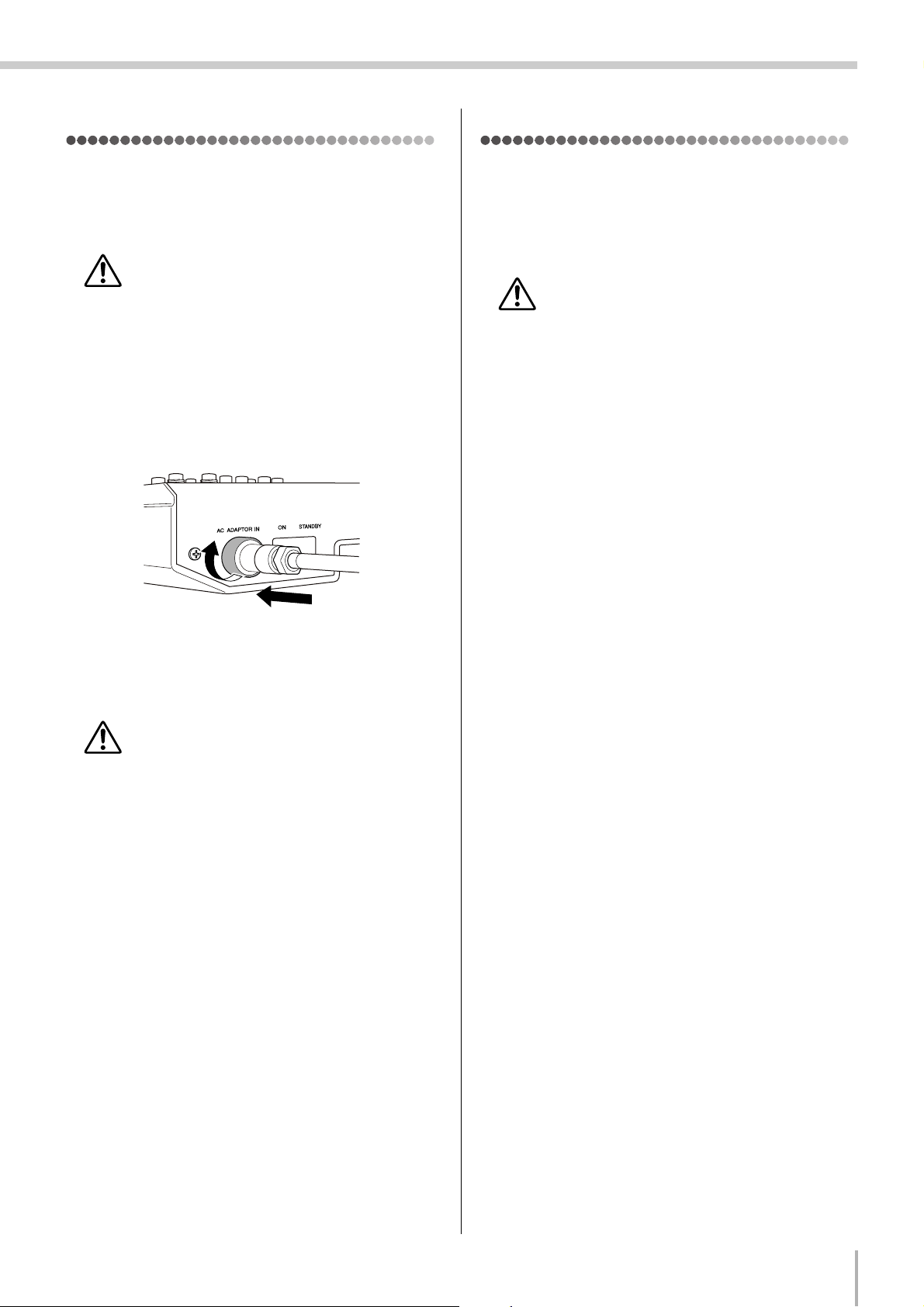
Connect the power adaptor to the AC ADAPTOR IN
2
connector (
the fastening ring clockwise (2) to secure the connec-
tion.
1
) on the rear of the mixer, and then turn
2
Turning the Power On
Press the mixer’s power switch to the ON position. When
you are ready to turn the power off, press the power switch to
the STANDBY position.
Note that trace current continues to flow while the
switch is in the STANDBY position. If you do not
plan to use the mixer again for a long while, please
be sure to unplug the adaptor from the wall outlet.
1
Plug the power adaptor into a standard household
3
power outlet.
• Be sure to unplug the adaptor from the outlet
when not using the mixer, or when there are lightning storms in the area.
• To avoid generating unwanted noise, make sure
there is 50 cm or more between the power adaptor
and the mixer.
MG8/2FX
5
Making the Most Of Your Mixer
Making the Most Of Your Mixer
■ An Introduction
You’ve got yourself a mixer and now you’re ready to use it.
Just plug everything in, twiddle the controls, and away you go … right?
Well, if you’ve done this before you won’t have any problems, but if this is
the first time you’ve ever used a mixer you might want to read through this little tutorial and pick up a few basics that will help you get better performance
and make better mixes.
1. A Place For Everything and Everything In Its Place
1-1. A Plethora Of Connectors—What Goes Where?
Questions you’re likely to encounter when setting up a system for the first time might include “Why all these different types of
connectors on the back of my mixer?” and “What’s the difference?”.
Let’s start by taking a look at the most common connector types.
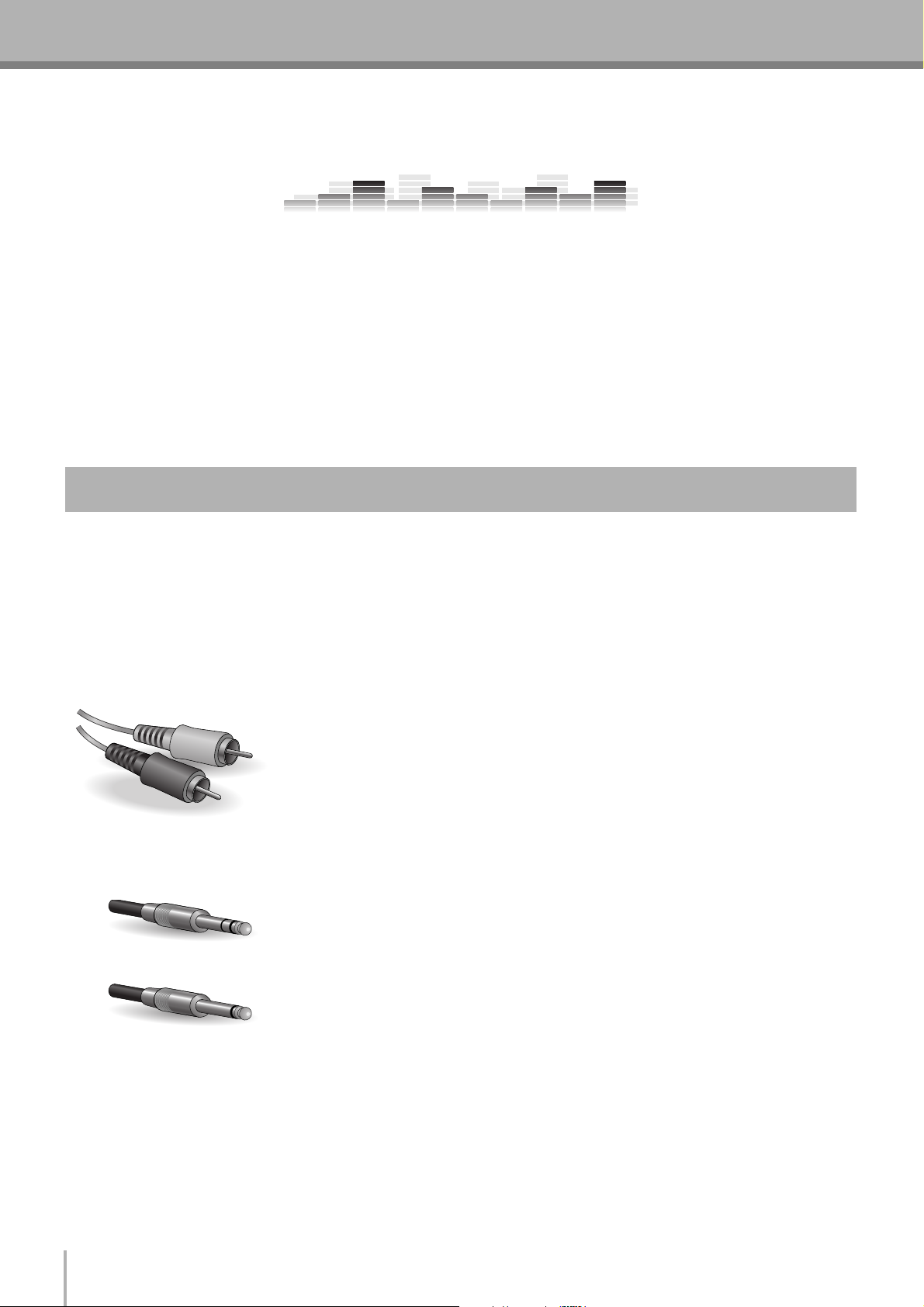
■ The Venerable RCA Pin Jack
White
Red
This is the “consumer connector,” and the one that has been most commonly used on
home audio gear for many years. Also known as “phono” jacks (short for “phonogram”),
but the term isn’t used much these days—besides, it’s too easily confusable with
“phone” jacks, below. RCA pin jacks are always unbalanced, and generally carry a
line-level signal at –10 dB, nominal. You’re most likely to use this type of connector
when connecting a CD player or other home audio type source to your mixer, or when
connecting the output of your mixer to a cassette recorder or similar gear.
■ The Versatile Phone Jack
The name “phone jack” arose simply because this configuration was first used in
telephone switchboards. Phone jacks can be tricky because you can’t always tell what
Stereo/TRS phone plug
Mono phone plug
type of signal they’re designed to handle just by looking at them. It could be unbalanced
mono, unbalanced stereo, balanced mono, or an insert patch point. The connector’s label
will usually tell you what type of signal it handles, as will the owner’s manual (you do
keep your manuals in a safe place, don’t you?). A phone jack that is set up to handle
balanced signals is also often referred to as a “TRS” phone jack. “TRS” stands for
Tip-Ring-Sleeve, which describes the configuration of the phone plug used.
MG8/2FX
6
Making the Most Of Your Mixer
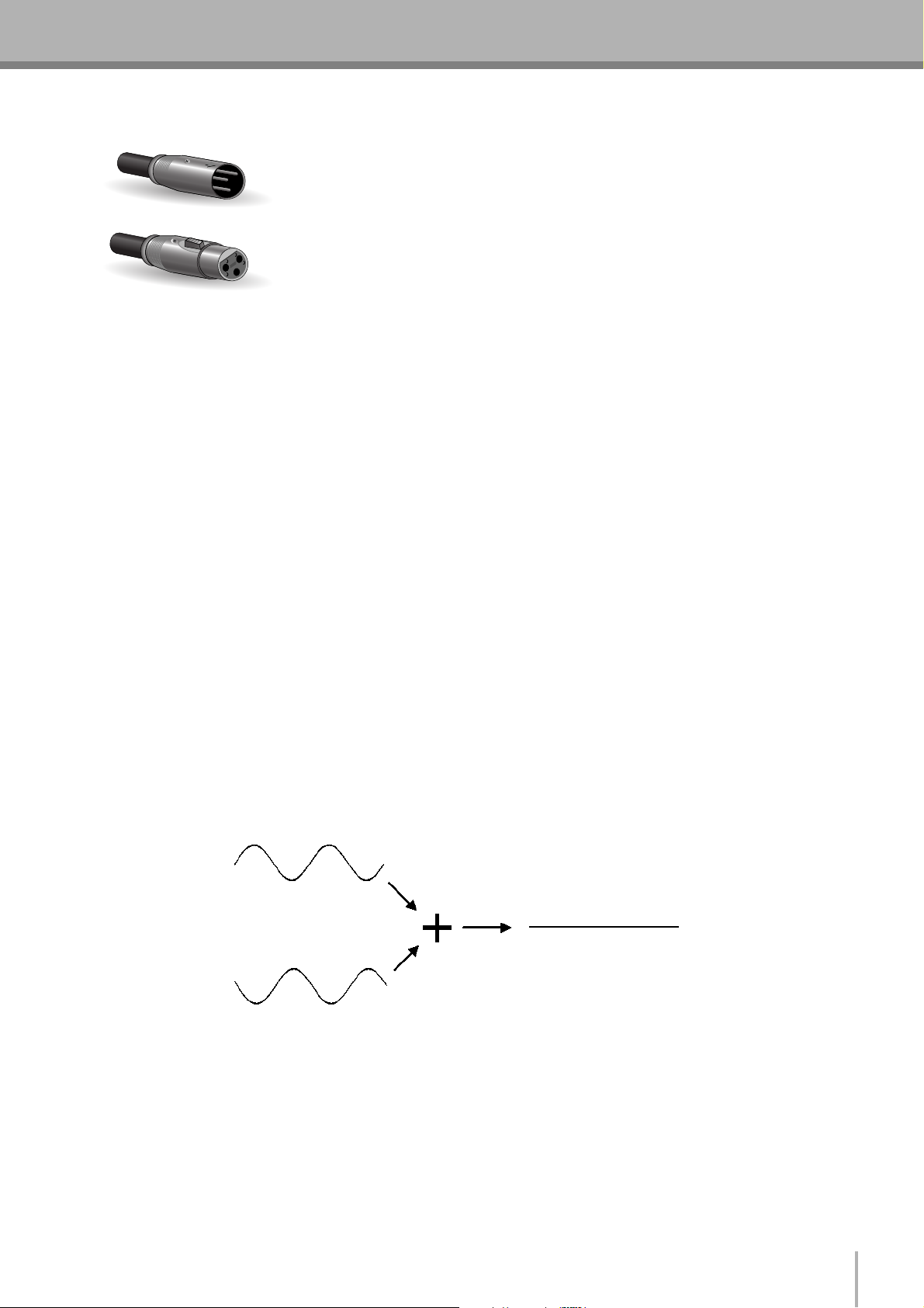
■ The Sturdy XLR
This type of connector is generally referred to as “XLR-type,” and almost always carries
a balanced signal. If the corresponding circuitry is designed properly, however,
XLR-type connectors will also handle unbalanced signals with no problem. Microphone
Male
Female
cables usually have this type of connector, as do the inputs and outputs of most
professional audio gear.
1-2. Balanced, Unbalanced—What’s the Difference?
In a word: “noise.” The whole point of balanced lines is noise rejection, and it’s something they’re very good at. Any length of
wire will act as an antenna to pick up the random electromagnetic radiation we’re constantly surrounded by: radio and TV
signals as well as spurious electromagnetic noise generated by power lines, motors, electric appliances, computer monitors, and
a variety of other sources. The longer the wire, the more noise it is likely to pick up. That’s why balanced lines are the best
choice for long cable runs. If your “studio” is basically confined to your desktop and all connections are no more than a meter or
two in length, then unbalanced lines are fine—unless you’re surrounded by extremely high levels of electromagnetic noise.
Another place balanced lines are almost always used is in microphone cables. The reason for this is that the output signal from
most microphones is very small, so even a tiny amount of noise will be relatively large, and will be amplified to an alarming
degree in the mixer’s high-gain head amplifier.
To summarize:
Microphones: Use balanced lines.
Short line-level runs: Unbalanced lines are fine if you’re in a relatively noise-free environment.
Long line-level runs: The ambient electromagnetic noise level will be the ultimate deciding factor, but balanced is
best.
■ How Do Balanced Lines Reject Noise?
** Skip this section if technical details make you queasy. **
Balanced lines work on the principle of “phase cancellation”: if you add two identical signals out of phase (i.e. one signal is
inverted so its peaks coincide with the troughs in the other signal), the result is … nothing. A flat line. The signals cancel each
other out.
Normal-phase signal.
No signal.
(Phase cancellation)
Reverse-phase signal.
MG8/2FX
7
Making the Most Of Your Mixer
A balanced cable has three conductors:
1) A ground conductor which carries no signal, just the “ground” or “0” reference against which the signal in the other conductors fluctuates.
2) A “hot” or “+” conductor which carries the normal-phase audio signal.
3) A “cold” or “–” conductor which carries the reverse-phase audio signal.
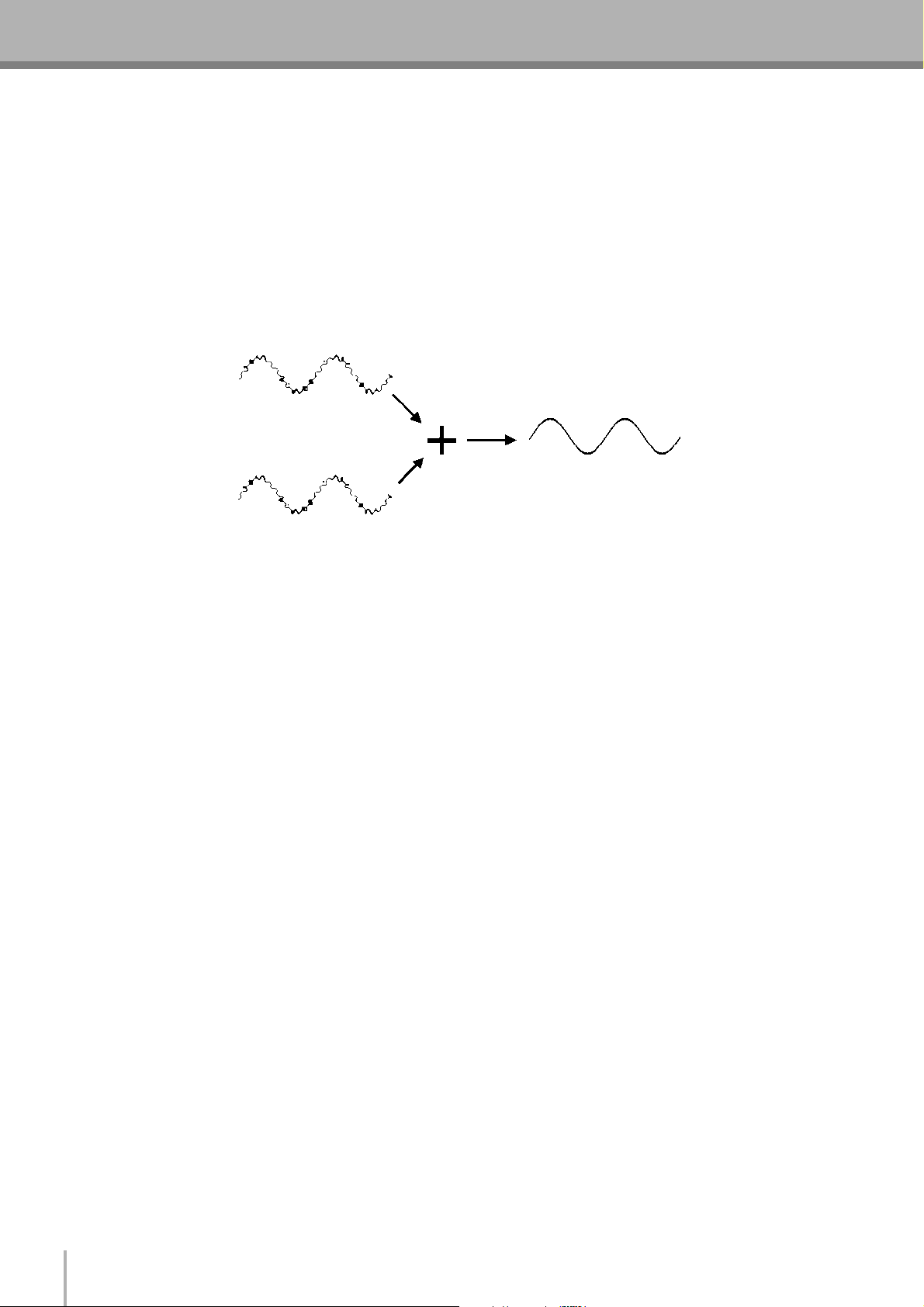
While the desired audio signals in the hot and cold conductors are out of phase, any noise induced in the line will be exactly the
same in both conductors, and thus in phase. The trick is that the phase of one signal is reversed at the receiving end of the line so
that the desired audio signals become in-phase, and the induced noise suddenly finds itself out of phase. The out-of-phase noise
signal is effectively canceled while the audio signal is left intact. Clever, eh?
Normal-phase signal
+ normal-phase noise.
Desired signal
with no noise.
Normal-phase signal
+ reverse-phase noise.
1-3. Signal Levels—Decibel Do’s and Don’ts
From the moment you start dealing with things audio, you’ll have to deal with the term “decibel” and its abbreviation, “dB”.
Things can get confusing because decibels are a very versatile unit of measure used to describe acoustic sound pressure levels as
well as electronic signal levels. To make matters worse there are a number of variations: dBu, dBV, dBm. Fortunately, you don’t
need to be an expert to make things work. Here are a few basics you should keep in mind:
● “Consumer” gear (such as home audio equipment) usually has line inputs and outputs with a nominal (average) level of
–10 dB.
● Professional audio gear usually has line inputs and outputs with a nominal level of +4 dB.
● You should always feed –10 dB inputs with a –10 dB signal. If you feed a +4 dB signal into a –10 dB input you are likely to
overload the input.
● You should always feed +4 dB inputs with a +4 dB signal. A –10 dB signal is too small for a +4 dB input, and will result in
less-than-optimum performance.
● Many professional and semi-professional devices have level switches on the inputs and/or outputs that let you select –10 or
+4 dB. Be sure to set these switches to match the level of the connected equipment.
● Inputs that feature a “Gain” control—such as the mono-channel inputs on your Yamaha mixer—will accept a very wide range
of input levels because the control can be used to match the input’s sensitivity to the signal. More on this later.
MG8/2FX
8
Making the Most Of Your Mixer
2. Where Your Signal Goes Once It’s Inside the Box
At first glance the block diagram of even a modest mixer can look like a space-station schematic. In reality, block diagrams are
a great aid in understanding how the signal flows in any mixer. Here’s a greatly simplified block diagram of a generic mixer to
help you become familiar with the way these things work.
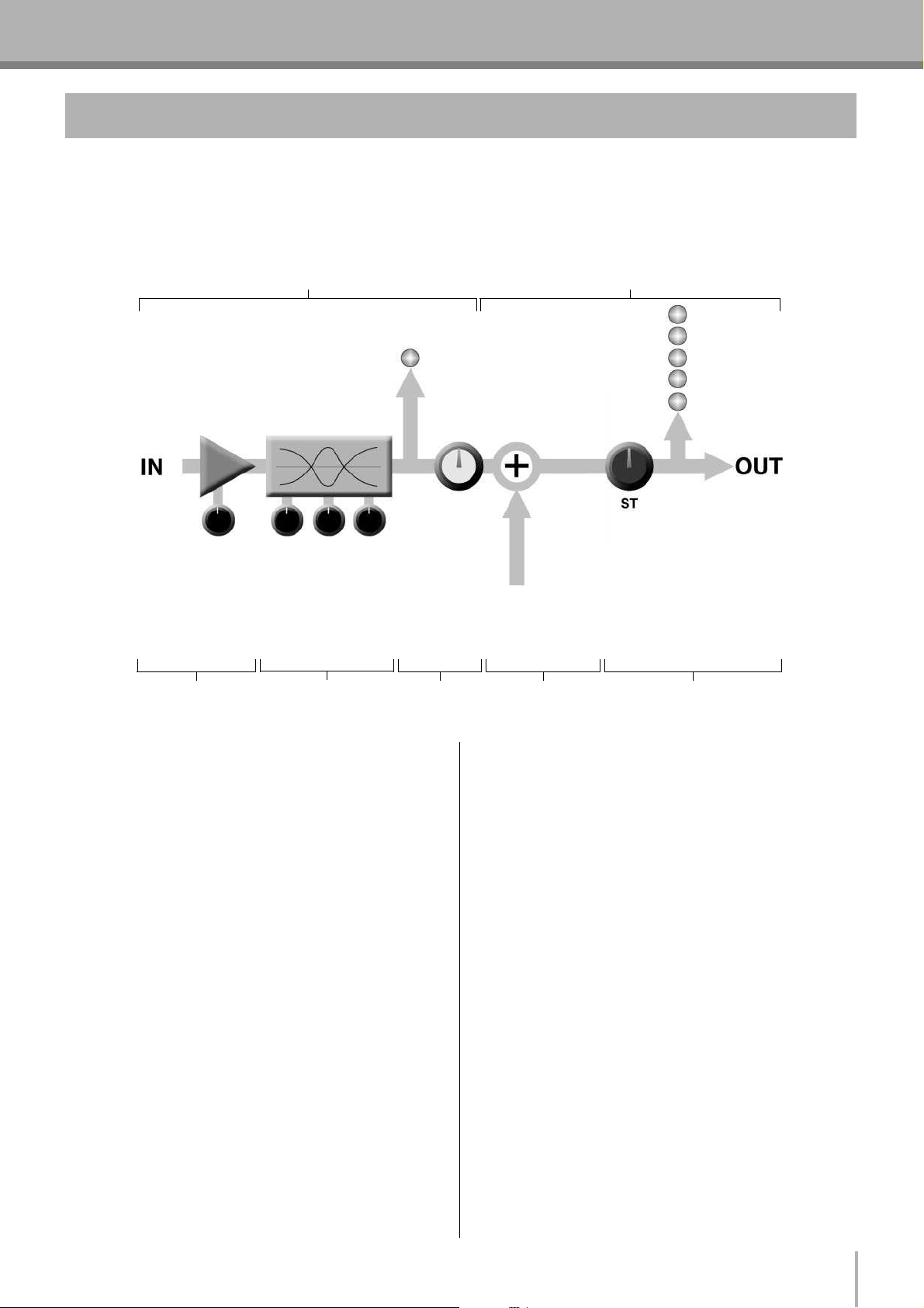
2-1. Greatly Simplified Mixer Block Diagram
Input Channel Master Section
1234 5
■ Input Channel
1 Head Amp
The very first stage in any mixer, and usually the only
stage with significant “gain” or “amplification.” The head
amp has a “gain” control that adjusts the mixer’s input
sensitivity to match the level of the source. Small signals
(e.g. mics) are amplified, and large signals are attenuated.
2 Equalizer
Could be simple bass and treble controls or a full-blown
4-band parametric EQ. When boost is applied the EQ
stage also has gain. You can actually overload the input
channel by applying too much EQ boost. It’s usually
better to cut than boost.
Signals from the mixer’s other
input channels (if they are
assigned to this master output
or “bus”).
■ Master Section
4 Summing Amplifier
This is where the actual “mixing” takes place. Signals
from all of the mixer’s input channels are “summed”
(mixed) together here.
5 Master Fader & Level Meter
A stereo, mono, or bus master fader and the mixer’s main
output level meter. There could be several master faders
depending on the design of the mixer—i.e. the number of
buses or outputs it provides.
3 Channel Peak LED & Fader
The channel peak LED is your most valuable tool for
setting the input “gain” control for optimum
performance. Note that it is located after the head amp
and EQ stage.
MG8/2FX
9
 Loading...