

Yamaha Audio MG32/14FX, MG24/14FX User Manual
MIXING CONSOLE
Owner’s Manual
MG32/14 FX
MG24/14 FX
E
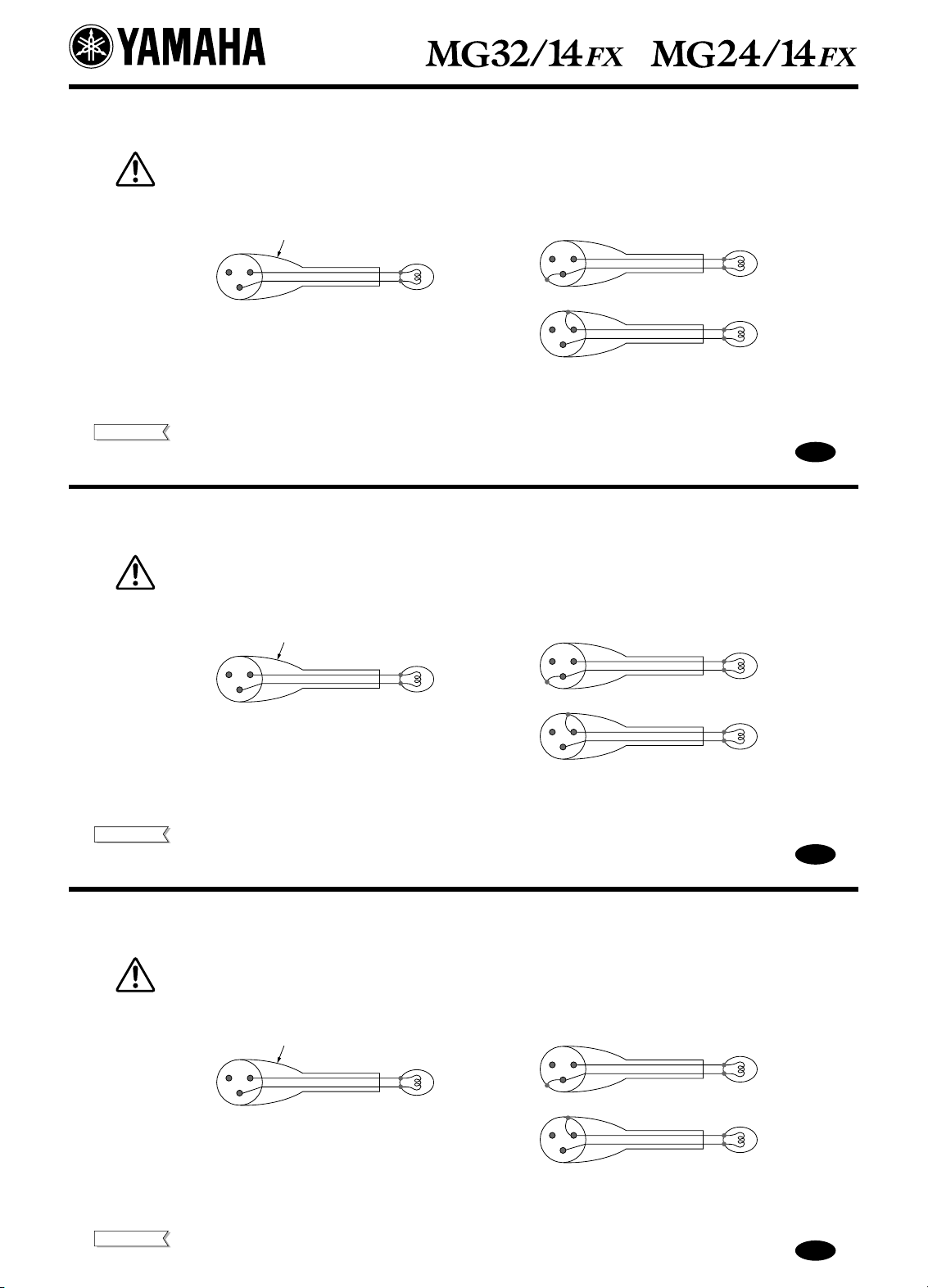
Important Notice – connecting a lamp –
Please read carefully before connecting a lamp to the LAMP Jack. (page 18)
• Do not use a lamp that grounds Pin 2 or Pin 3 to the shell (body). Use of the wrong lamp type may result in damage
to the mixer. Recommended lamps: Littlite’s X-HI series of gooseneck lamps.
Correct lamp type
Shell
12
3
Wrong lamp type
12
3
12
3
• Do not inadvertently connect a talkback microphone to the LAMP jack. A microphone may sustain damage if connected to this jack.
NOTE
Supported lamps: 12V (AC or DC), max. 5W.
Supplies 12V to Pins 2 and 3. Pin 1 is not connected.
Wichtiger Hinweis – eine Leuchte anschließen –
Bitte lesen Sie diesen Abschnitt sorgfältig, bevor Sie die Leuchte an der Buchse LAMP anschließen. (Seite 18)
• Verwenden Sie keine Leuchte, die Pin 2 oder Pin 3 mit der Masse verbindet (Chassis). Einsatz der falschen Leuchte
kann Schäden am Mischpult verursachen. Empfohlene Leuchten: Schwanenhalsleuchten der Reihe X-HI von Littlite.
Richtiger Leuchtentyp
Masse
12
3
Falscher Leuchtentyp
12
3
E
12
3
• Schließen Sie nicht versehentlich ein Talkback-Mikrofon an der Buchse LAMP an. Ein an dieser Buchse angeschlossenes Mikrofon könnte beschädigt werden.
HINWEIS
Unterstützte Leuchten: 12 V (Gleich- oder Wechselstrom), max. 5 W.
Liefert 12 V an Pins 2 und 3. Pin 1 ist nicht verbunden.
Remarque importante – Branchement d’une lampe –
Prière de lire attentivement avant de brancher une lampe dans la Prise jack LAMP. (page 18)
• N’utilisez pas de lampe mettant à la masse les broches 2 ou 3 sur le boîtier. L’utilisation d’un type de lampe incorrect
peut endommager la console. Lampes recommandées : lampes en col de cygne Littlite, série X-HI.
Type de lampe incorrect
12
3
12
3
• Ne branchez pas par inadvertance un microphone talkback dans la prise jack LAMP.
REMARQUE
Type de lampe correct
Boîtier
12
3
Tout microphone branché dans cette prise risque d’être endommagé.
Lampes prises en charge : 12 V (c.a. ou c.c.), puissance max. de 5 W.
Fournit une tension de 12 V aux broches 2 et 3. La broche 1 n’est pas connectée.
G
F
CAUTION
RISK OF ELECTRIC SHOCK
DO NOT OPEN
CAUTION: TO REDUCE THE RISK OF
ELECTRIC SHOCK, DO NOT REMOVE
COVER (OR BACK). NO USER-SERVICEABLE
PARTS INSIDE. REFER SERVICING TO
QUALIFIED SERVICE PERSONNEL.
The above warning is located on the rear
of the unit
IMPORTANT SAFETY INSTRUCTIONS
• Explanation of Graphical Symbols
The lightning flash with arrowhead symbol
within an equilateral triangle is intended to
alert the user to the presence of uninsulated
“dangerous voltage” within the product’s
enclosure that may be of sufficient magnitude
to constitute a risk of electric shock to persons.
The exclamation point within an equilateral
triangle is intended to alert the user to the presence of important operating and maintenance
(servicing) instructions in the literature
accompanying the product.
1 Read these instructions.
2 Keep these instructions.
3 Heed all warnings.
4 Follow all instructions.
5 Do not use this apparatus near water.
6 Clean only with dry cloth.
7 Do not block any ventilation openings. Install in
accordance with the manufacturer’s instructions.
8 Do not install near any heat sources such as
radiators, heat registers, stoves, or other apparatus (including amplifiers) that produce heat.
9 Do not defeat the safety purpose of the polar-
ized or grounding-type plug. A polarized plug
has two blades with one wider than the other. A
grounding type plug has two blades and a third
grounding prong. The wide blade or the third
prong are provided for your safety. If the provided plug does not fit into your outlet, consult
an electrician for replacement of the obsolete
outlet.
10 Protect the power cord from being walked on or
pinched particularly at plugs, convenience
receptacles, and the point where they exit from
the apparatus.
11 Only use attachments/accessories specified by
the manufacturer.
12 Use only with the cart, stand,
tripod, bracket, or table specified by the manufacturer, or
sold with the apparatus.
When a cart is used, use caution when moving the cart/
apparatus combination to
avoid injury from tip-over.
Unplug this apparatus during lightning storms
13
or when unused for long periods of time.
14 Refer all servicing to qualified service person-
nel. Servicing is required when the apparatus
has been damaged in any way, such as powersupply cord or plug is damaged, liquid has been
spilled or objects have fallen into the apparatus,
the apparatus has been exposed to rain or moisture, does not operate normally, or has been
dropped.
WARNING
TO REDUCE THE RISK OF FIRE OR ELECTRIC SHOCK,
DO NOT EXPOSE THIS APPARATUS TO RAIN OR MOISTURE.
MG32/14FX, MG24/14FX
2
PRECAUTIONS
PLEASE READ CAREFULLY BEFORE PROCEEDING
* Please keep this manual in a safe place for future reference.
WARNING
Always follow the basic precautions listed below to avoid the possibility of serious injury or even death from electrical shock,
short-circuiting, damages, fire or other hazards. These precautions include, but are not limited to, the following:
Power supply/Power cord
• Only use the voltage specified as correct for the device. The
required voltage is printed on the name plate of the device.
• Use only the included power cord.
• Do not place the power cord near heat sources such as
heaters or radiators, and do not excessively bend or otherwise
damage the cord, place heavy objects on it, or place it in a
position where anyone could walk on, trip over, or roll anything
over it.
Do not open
• Do not open the device or attempt to disassemble the internal
parts or modify them in any way. The device contains no
user-serviceable parts. If it should appear to be
malfunctioning, discontinue use immediately and have it
inspected by qualified Yamaha service personnel.
Water warning
• Do not expose the device to rain, use it near water or in damp
or wet conditions, or place containers on it containing liquids
which might spill into any openings.
• Never insert or remove an electric plug with wet hands.
If you notice any abnormality
• If the power cord or plug becomes frayed or damaged, or if
there is a sudden loss of sound during use of the device, or if
any unusual smells or smoke should appear to be caused by it,
immediately turn off the power switch, disconnect the electric
plug from the outlet, and have the idevice inspected by
qualified Yamaha service personnel.
• If this device should be dropped or damaged, immediately turn
off the power switch, disconnect the electric plug from the
outlet, and have the device inspected by qualified Yamaha
service personnel.
CAUTION
Always follow the basic precautions listed below to avoid the possibility of physical injury to you or others, or damage to the
device or other property. These precautions include, but are not limited to, the following:
Power supply/Power cord
• Remove the electric plug from the outlet when the device is not
to be used for extended periods of time, or during electrical
storms.
• When removing the electric plug from the device or an outlet,
always hold the plug itself and not the cord. Pulling by the cord
can damage it.
- On a thick carpet or other such surface
- While it is inside an unventilated touring case
Failure to observe the above precautions may cause the
device to overheat, resulting in equipment damage and fire
hazard.
• Do not use the device in the vicinity of a TV, radio, stereo
equipment, mobile phone, or other electric devices. Otherwise,
the device, TV, or radio may generate noise.
Location
• When transporting or moving the device, always use two or
more people.
• Before moving the device, remove all connected cables.
• Avoid setting all equalizer controls and faders to their
maximum. Depending on the condition of the connected
devices, doing so may cause feedback and may damage the
speakers.
• Do not expose the device to excessive dust or vibrations, or
extreme cold or heat (such as in direct sunlight, near a heater,
or in a car during the day) to prevent the possibility of panel
disfiguration or damage to the internal components.
• Do not place the device in an unstable position where it might
accidentally fall over.
• Never block the vent holes during use. Vent holes are located
on the top, bottom, front, rear, and sides of this machine. All
vent holes must remain unblocked to prevent overheating.
To further ensure adequate ventilation, never use this device…
- Upside down or on its side
- In a poorly ventilated location (in a closet, inside a
bookcase, etc.)
- With its rubber footpads removed
Connections
• Before connecting the device to other devices, turn off the
power for all devices. Before turning the power on or off for all
devices, set all volume levels to minimum.
Handling caution
• Do not insert your finger or hand in any gaps or openings on
the device (vents, etc.).
• Avoid inserting or dropping foreign objects (paper, plastic,
metal, etc.) into any gaps or openings on the device (vents,
etc.). If this happens, turn off the power immediately and
unplug the power cord from the AC outlet. Then have the
device inspected by qualified Yamaha service personnel.
• Do not use the device or headphones for a long period of time
at a high or uncomfortable volume level, since this can cause
permanent hearing loss. If you experience any hearing loss or
ringing in the ears, consult a physician.
• Do not rest your weight on the device or place heavy objects
on it, and avoid use excessive force on the buttons, switches or
connectors.
MG32/14FX, MG24/14FX
3
XLR-type connectors are wired as follows (IEC60268 standard): pin 1: ground, pin 2: hot (+), and pin 3: cold (–).
Insert TRS phone jacks are wired as follows: sleeve: ground, tip: send, and ring: return.
Yamaha cannot be held responsible for damage caused by improper use or modifications to the device, or data that is lost or destroyed.
Always turn the power off when the device is not in use.
The performance of components with moving contacts, such as switches, volume controls, and connectors, deteriorates over time. Consult qualified Yamaha service personnel about replacing defective components.
Copying of commercially available music data and/or digital audio files, except for personal use, is strictly prohibited.
Illustrations in this manual are for explanatory purposes only, and may not match the actual appearance of the product during operation.
Company names and product names used in this Owner’s Manual are trademarks or registered trademarks of their respective owners.
FCC INFORMATION (U.S.A.)
1. IMPORTANT NOTICE: DO NOT MODIFY THIS UNIT!
This product, when installed as indicated in the instructions contained in this manual, meets FCC requirements. Modifications
not expressly approved by Yamaha may void your authority,
granted by the FCC, to use the product.
2. IMPORTANT: When connecting this product to accessories
and/or another product use only high quality shielded cables.
Cable/s supplied with this product MUST be used. Follow all
installation instructions. Failure to follow instructions could void
your FCC authorization to use this product in the USA.
3. NOTE: This product has been tested and found to comply with
the requirements listed in FCC Regulations, Part 15 for Class “B”
digital devices. Compliance with these requirements provides a
reasonable level of assurance that your use of this product in a
residential environment will not result in harmful interference with
other electronic devices. This equipment generates/uses radio
frequencies and, if not installed and used according to the
instructions found in the users manual, may cause interference
harmful to the operation of other electronic devices. Compliance
with FCC regulations does not guarantee that interference will
not occur in all installations. If this product is found to be the
source of interference, which can be determined by turning the
unit “OFF” and “ON”, please try to eliminate the problem by using
one of the following measures:
Relocate either this product or the device that is being affected by
the interference.
Utilize power outlets that are on different branch (circuit breaker
or fuse) circuits or install AC line filter/s.
In the case of radio or TV interference, relocate/reorient the
antenna. If the antenna lead-in is 300 ohm ribbon lead, change
the lead-in to co-axial type cable.
If these corrective measures do not produce satisfactory results,
please contact the local retailer authorized to distribute this type
of product. If you can not locate the appropriate retailer, please
contact Yamaha Corporation of America, Electronic Service Division, 6600 Orangethorpe Ave, Buena Park, CA90620
The above statements apply ONLY to those products distributed
by Yamaha Corporation of America or its subsidiaries.
* This applies only to products distributed by YAMAHA CORPORATION OF AMERICA. (class B)
IMPORTANT NOTICE FOR THE UNITED KINGDOM
Connecting the Plug and Cord
WARNING: THIS APPARATUS MUST BE EARTHED
IMPORTANT. The wires in this mains lead are coloured in accordance with the following code:
GREEN-AND-YELLOW : EARTH
BLUE : NEUTRAL
BROWN : LIVE
As the colours of the wires in the mains lead of this apparatus may not correspond with the coloured makings identifying the terminals in your
plug proceed as follows:
The wire which is coloured GREEN-and-YELLOW must be connected to the terminal in the plug which is marked by the letter E or by the safety
earth symbol or coloured GREEN or GREEN-and-YELLOW.
The wire which is coloured BLUE must be connected to the terminal which is marked with the letter N or coloured BLACK.
The wire which is coloured BROWN must be connected to the terminal which is marked with the letter L or coloured RED.
• This applies only to products distributed by Yamaha-Kemble Music (U.K.) Ltd. (3 wires).
MG32/14FX, MG24/14FX
4

MG32/14FX, MG24/14FX
5

Introduction
Thank you for your purchase of the YAMAHA MG32/14FX or MG24/14FX mixing console.
This console offers excellent cost-performance and is ideal for use as the main mixer in an
SR setup or as part of an installed system.
Please read through this Owner’s Manual carefully before beginning use, so that you will be
able to take full advantage of the mixer’s superlative features and enjoy trouble-free operation
for years to come. Be sure to retain this manual in a safe place.
Features Contents
● Provides 24 (MG32/14FX) or 16 (MG24/14FX) monaural input
channels suitable for connection to both microphones and
line-level devices. Also provides four line-level stereo inputs.
● Built-in dual digital effector, based on Yamaha’s acclaimed SPX
multi-effector technology, can apply a variety of internal effects
to both vocal and instrumental inputs.
● Convenient “tap delay” feature lets you set the internal effect’s
delay time by tapping on a button (or by stepping on a separately-sold foot switch).
Provides dual stereo outputs, two effect outputs, six AUX out-
●
puts, and four group outputs—for a total of 14 outputs. You can
use the AUX and GROUP outputs both to connect to external
devices (such as effectors and MTRs) and to create custom
mixes for targeted speakers or amps for stage monitoring.
● An independently controlled MONO output jack feeds out a mix
of the main ST output signal, ideal for connection to a subwoofer
or other SR system extension.
● All monaural channels are equipped with an INSERT I/O jack
for independent connection to an external effector.
● Includes independent PFL switches for each input channel, for
each AUX return, and for the 2TR IN bus, together with independent AFL switches for each AUX and GROUP output and for
the main ST output. These switches make it easy to selectively
monitor the input and output signals through headphones connected to the PHONES jack.
● Phantom power supply can provide DC +48 power to all XLR
input jacks, allowing you to connect phantom-powered condenser mics and direct boxes to any combination of monaural
channels. The phantom power can be independently switched on
and off in eight-channel blocks.
● Dual RETURN jacks can feed AUX return signals not only into
the ST bus but also into four of the AUX buses. These jacks can
also serve as an auxiliary stereo input.
Introduction ............................................................... 6
Features............................................................... 6
Connecting to Power............................................ 7
Setting Up............................................................ 7
Front & Rear Panels .................................................. 8
Channel Control Block....................................... 10
Master Control Block ......................................... 13
Rear Input/Output Block .................................... 19
Appendix ................................................................. 22
Specifications .................................................... 22
Dimensional Diagrams....................................... 25
Block and Level Diagram ................................... 26
MG32/14FX, MG24/14FX
6
Connecting to Power Setting Up
Introduction
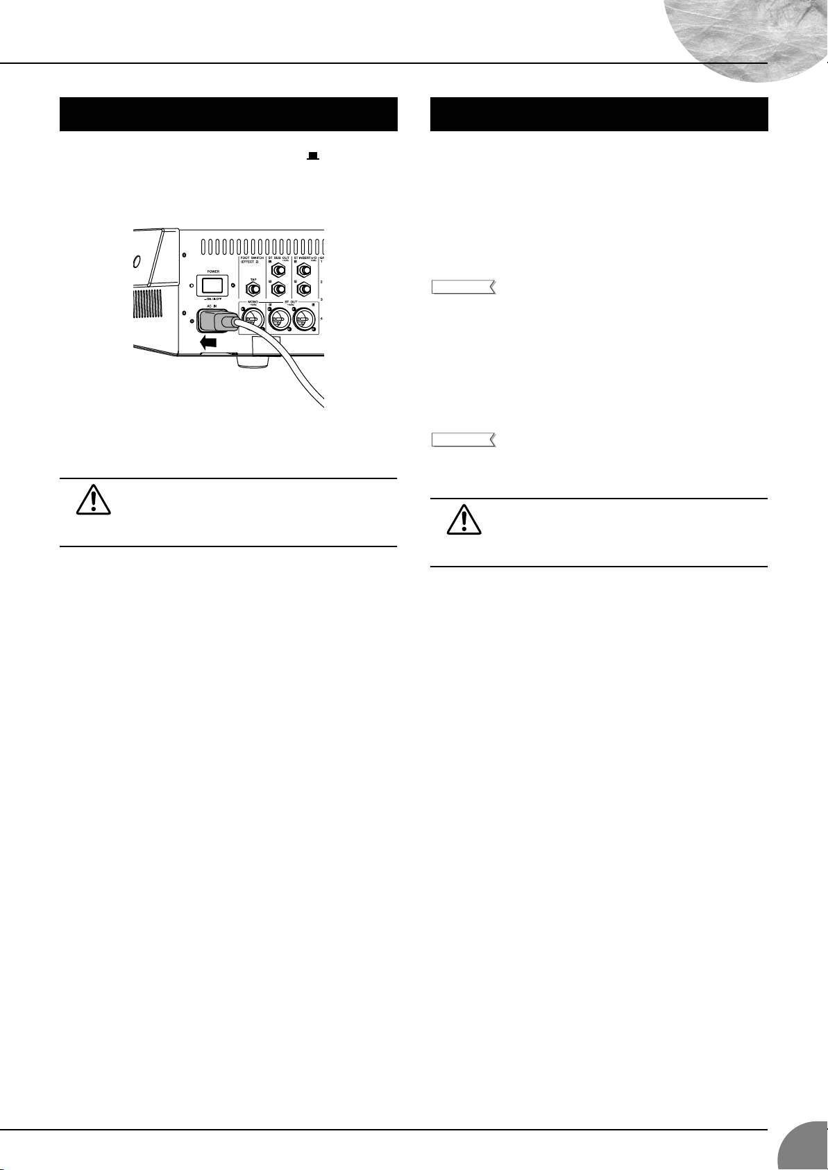
(1) Be sure that the mixer’s power switch is off ( ).
(2) Connect the socket end of the power cord to the AC IN connec-
tor on the rear of the mixer.
(3) Plug the other end of the power cord into a standard household
power outlet.
Be sure to unplug the power cord from the outlet if
you are not going to use the mixer again for an
extended period, and whenever there are lightning
storms in the area.
(1) Before connecting to microphones and instruments, be sure
that all devices are turned off. Also be sure that all of the
mixer’s channel faders and master control faders are set all the
way down.
(2) For each connection, connect one end of the cable to the rele-
vant microphone or instrument and connect the other end to the
appropriate input jack on the mixer.
NOTE
(3) Power up the devices in the following order: Peripheral devices
→ mixer → power amps (or powered speakers).
NOTE
On each monaural channel, you may use either
INPUT A or INPUT B, but not both. On stereo channels that provide both a phone input jack and an
RCA-pin input jack, you may use either of these but
not both. Please connect to only one of these jacks
on each channel.
When shutting the system down, turn off the power
in the opposite order: Power amps (powered speakers) → mixer → peripheral devices.
Do not block the vents. Vent holes are located on the
top, bottom, front, rear, and sides of this machine. All
vent holes must remain unblocked to prevent overheating.
MG32/14FX, MG24/14FX
7
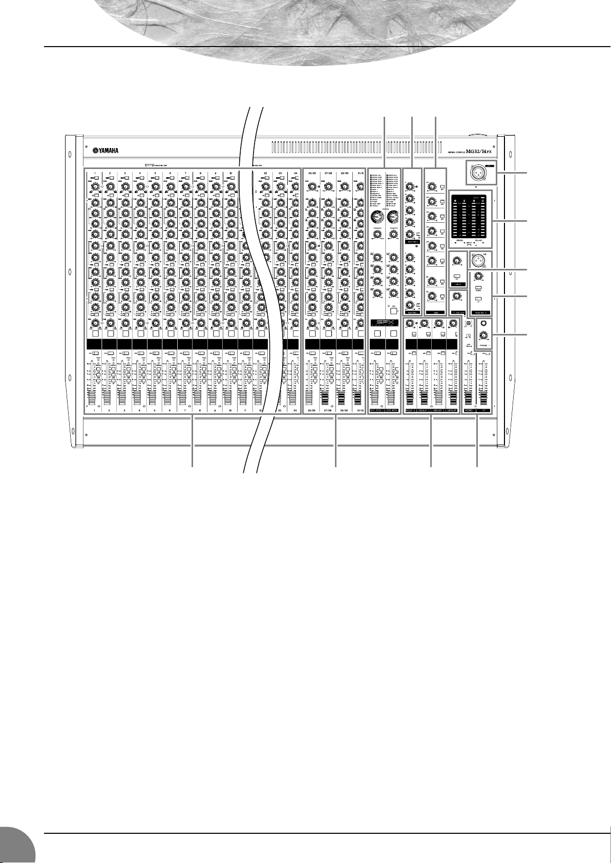
Front Panel
Front & Rear Panels
6 5
7
11
8
9
10
1
Note: Within this manual, all panel illustrations show the MG32/14FX panel.
Channel Control Block Master Control Block
MONAURAL CHANNELS Section (p. 10)
1
STEREO CHANNELS Section (p. 10)
2
STEREO/MONO Section (p. 13)
3
GROUP Section (p. 14)
4
SEND Section (p. 14)
5
RETURN Section (p. 15)
6
8
342
MG32/14FX, MG24/14FX
8
INTERNAL DIGITAL EFFECTS Section (p. 16)
7
METER/PHONES Section (p. 17)
8
2TR INPUT Section (p. 17)
9
TALKBACK Section (p. 18)
10
LAMP Jack (p. 18)
11
 Loading...