

Yamaha Audio MDX-M5 User Manual

UCAB
M D X -M 5
Minidisc Recorder
Lecteur Enregistreur De Minidisc
OWNER’S MANUAL
MODE D’EMPLOI
SAFETY INSTRUCTIONS
6A A unit and cart combination should be
CAUTION
RISK OF ELECTRIC SHOCK
DO NOT OPEN
7 Wall or Ceiling Mounting – The unit
CAUTION: TO REDUCE THE RISK OF
ELECTRIC SHOCK, DO NOT REMOVE
COVER (OR BACK). NO USER-SERVICEABLE
PARTS INSIDE. REFER SERVICING TO
QUALIFIED SERVICE PERSONNEL.
• Explanation of Graphical Symbols
The lightning flash with arrowhead symbol,
within an equilateral triangle, is intended to
alert you to the presence of uninsulated
“dangerous voltage” within the product’s
enclosure that may be of sufficient magnitude
to constitute a risk of electric shock to
persons.
The exclamation point within an equilateral
triangle is intended to alert you to the
presence of important operating and
maintenance (servicing) instructions in the
literature accompanying the appliance.
WARNING
TO REDUCE THE RISK OF FIRE OR ELECTRIC
SHOCK, DO NOT EXPOSE THIS UNIT TO RAIN OR
MOISTURE.
IMPORTANT!
Please record the serial number of this unit in the
space below.
Model:
Serial No.:
The serial number is located on the rear of the unit.
Retain this Owner’s Manual in a safe place for future
reference.
1 Read Instructions – All the safety and operating
instructions should be read before the unit is
operated.
2 Retain Instructions – The safety and operating
instructions should be retained for future reference.
3 Heed Warnings – All warnings on the unit and in the
operating instructions should be adhered to.
4 Follow Instructions – All operating and other
instructions should be followed.
5 Water and Moisture – The unit should not be used
near water – for example, near a bathtub, washbowl,
kitchen sink, laundry tub, in a wet basement, or near a
swimming pool, etc.
6 Carts and Stands – The unit should be used only with
a cart or stand that is recommended by the
manufacturer.
8 Ventilation – The unit should be situated so that its
9 Heat – The unit should be situated away from heat
10 Power Sources – The unit should be connected to a
11 Power-Cord Protection – Power-supply cords should
12 Cleaning – The unit should be cleaned only as
13 Nonuse Periods – The power cord of the unit should
14 Object and Liquid Entry – Care should be taken so
15 Damage Requiring Service – The unit should be
16 Servicing – The user should not attempt to service the
17 Power Lines – An outdoor antenna should be located
18 Grounding or Polarization – Precautions should be
moved with care. Quick stops,
excessive force, and uneven surfaces
may cause the unit and cart
combination to overturn.
should be mounted to a wall or ceiling only as
recommended by the manufacturer.
location or position does not interfere with its proper
ventilation. For example, the unit should not be
situated on a bed, sofa, rug, or similar surface, that
may block the ventilation openings; or placed in a
built-in installation, such as a bookcase or cabinet that
may impede the flow of air through the ventilation
openings.
sources such as radiators, stoves, or other appliances
that produce heat.
power supply only of the type described in the
operating instructions or as marked on the unit.
be routed so that they are not likely to be walked on or
pinched by items placed upon or against them, paying
particular attention to cords at plugs, convenience
receptacles, and the point where they exit from the
unit.
recommended by the manufacturer.
be unplugged from the outlet when left unused for a
long period of time.
that objects do not fall into and liquids are not spilled
into the inside of the unit.
serviced by qualified service personnel when:
A. The power-supply cord or the plug has been
damaged; or
B. Objects have fallen, or liquid has been spilled into
the unit; or
C. The unit has been exposed to rain; or
D. The unit does not appear to operate normally or
exhibits a marked change in performance; or
E. The unit has been dropped, or the cabinet
damaged.
unit beyond those means described in the operating
instructions. All other servicing should be referred to
qualified service personnel.
away from power lines.
taken so that the grounding or polarization is not
defeated.
22
FCC INFORMATION (for US customers only)
1. IMPORTANT NOTICE: DO NOT MODIFY THIS UNIT!
This product, when installed as indicated in the
instructions contained in this manual, meets FCC
requirements. Modifications not expressly approved by
Yamaha may void your authority, granted by the FCC,
to use the product.
2. IMPORTANT: When connecting this product to
accessories and/or another product use only high
quality shielded cables. Cable/s supplied with this
product MUST be used. Follow all installation
instructions. Failure to follow instructions could void
your FCC authorization to use this product in the USA.
3. NOTE: This product has been tested and found to
comply with the requirements listed in FCC
Regulations, Part 15 for Class “B” digital devices.
Compliance with these requirements provides a
reasonable level of assurance that your use of this
product in a residential environment will not result in
harmful interference with other electronic devices.
This equipment generates/uses radio frequencies and,
if not installed and used according to the instructions
found in the users manual, may cause interference
harmful to the operation of other electronic devices.
Compliance with FCC regulations does not guarantee
that interference will not occur in all installations. If this
product is found to be the source of interference, which
can be determined by turning the unit “OFF” and “ON”,
please try to eliminate the problem by using one of the
following measures:
Relocate either this product or the device that is being
affected by the interference.
Utilize power outlets that are on different branch (circuit
breaker or fuse) circuits or install AC line filter/s.
In the case of radio or TV interference, relocate/reorient
the antenna. If the antenna lead-in is 300 ohm ribbon
lead, change the lead-in to coaxial type cable.
If these corrective measures do not produce satisfactory
results, please contact the local retailer authorized to
distribute this type of product. If you can not locate the
appropriate retailer, please contact Yamaha Electronics
Corp., U.S.A. 6660 Orangethorpe Ave, Buena Park, CA
90620.
The above statements apply ONLY to those products
distributed by Yamaha Corporation of America or its
subsidiaries.
We Want You Listening For A Lifetime
YAMAHA and the Electronic Industries Association’s Consumer Electronics Group want you to get the
most out of your equipment by playing it at a safe level. One that lets the sound come through loud and
clear without annoying blaring or distortion – and, most importantly, without affecting your sensitive
hearing. Since hearing damage from loud sounds is often undetectable until it is too late, YAMAHA and
the Electronic Industries Association’s Consumer Electronics Group recommend you to avoid prolonged
exposure from excessive volume levels.
E nglish
For U.K. customers
If the socket outlets in the home are not suitable for the
plug supplied with this appliance, it should be cut off
and an appropriate 3 pin plug fitted. For details, refer to
the instructions described below.
Note: The plug severed from the mains lead must be
destroyed,
if engaged in a live
as a plug with bared flexible cord is hazardous
socket outlet.
SPECIAL INSTRUCTIONS FOR U.K.
MODEL
IMPORTANT:
The wire in the mains lead are coloured in accordance with the following code:
Blue: NEUTRAL
Brown: LIVE
As the colours of the wires in the mains lead of this
apparatus
markings identifying the terminals in your plug,
proceed as follows: The wire which is coloured
BLUE must be connected to the terminal which is
marked with the letter N or coloured BLACK. The
wire which is coloured BROWN must be connected
to the terminal which is marked with the letter L or
coloured RED. Making sure that neither core is
connected to the earth terminal of the three pin
plug.
may not correspond with the coloured
33
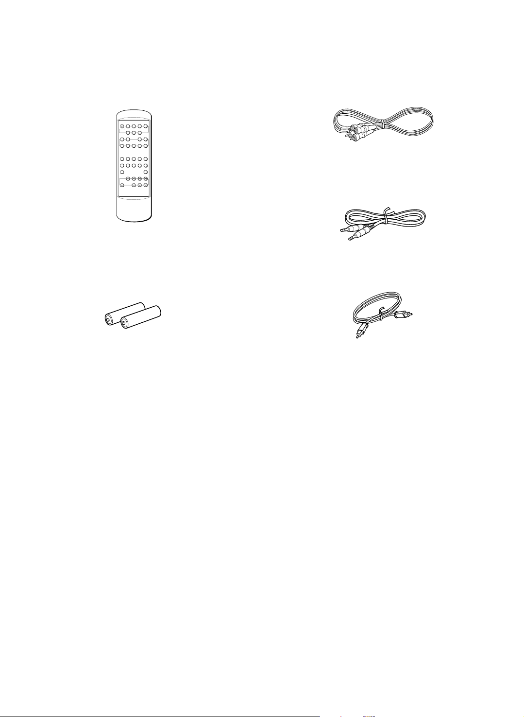
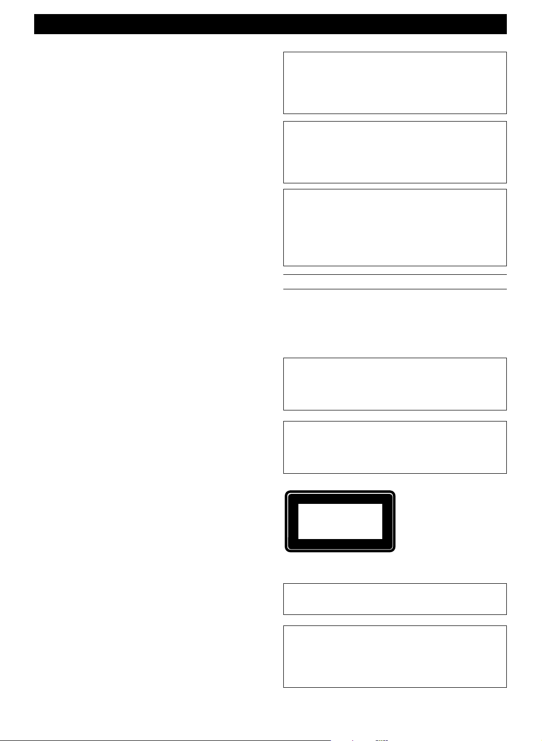
SUPPLIED ACCESSORIES • After unpacking, check that the following parts are contained.
ACCESSOIRES FOURNIS • Après le déballage, vérifier que les pièces suivantes sont incluses.
• Remote control transmitter
• Télécommande
AUTO
POWER RANDOM REPEAT
PAUSE DISPLAY
/
REC
REC
AUTO/
INPUT
MODE
MANUAL
EDIT
TITLE
TITLE
CANCEL
EDIT
SEARCH
INPUT
PGM CHECK CLEAR ENTERSET
CHARAC SPACE DELETE
A B C D E F J K LG H I
1
2345
M N O P R S T U V Q ZW X Y
67890
& ( ) – / ’ , : ? !
+100
+10
REC
• Batteries (size AAA, UM/SEM-4, R7, HP-8)
• Piles (format AAA, UM/SEM-4, R7, HP-8)
• Audio connecting cable
• Câbles de connexion audio
• System cable
• Câble système
• Optical fiber cable
• Câble de fibres optiques
44
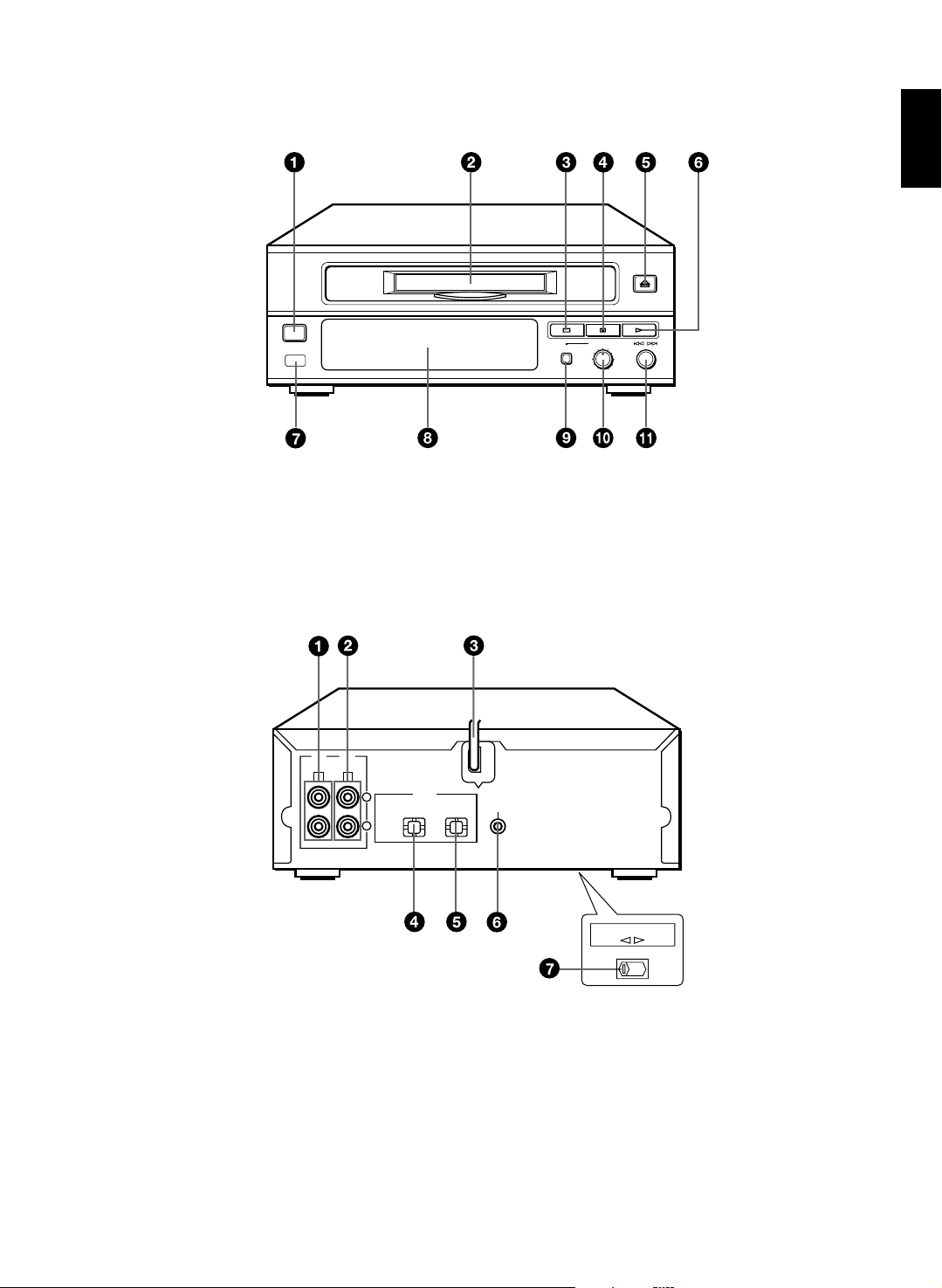
FRONT PANEL
PANNEAU FRONTAL
REAR PANEL
PANNEAU ARRIERE
STANDBY/ON
E nglish
REC LEVEL
REC
– +
010
LINE
OUT
C D
LINE
IN
DIGITAL
L
R
OPTICAL
IN OUT
SYSTEM
CONNECTOR
VOLTAGE SELECTOR
115V 230V
55
DISPLAY
PANNEAU D’AFFICHAGE
REPEAT LPGM MONO
REC
TITLE SEARCH –dB 30 18 12 7 3 0 OVER ANALOG DIGITAL
RANDOM
SINGLE
TOTAL
REMAIN
REMOTE CONTROL TRANSMITTER
TELECOMMANDE
R
A.PAUSE MANUAL
32
44.1
48
kHz
kHz
kHz
AUTO
REC
MODE
PAUSE DISPLAY
AUTO/
MANUAL
TITLE
TITLE
SEARCH
INPUT
POWER RANDOM REPEAT
/
REC
INPUT
EDIT
CANCEL
EDIT
PGM CHECK CLEAR ENTERSET
CHARAC SPACE DELETE
A B C D E F J K LG H I
1
2345
M N O P R S T U V Q ZW X Y
67890
& ( ) – / ’ , : ? !
+100
REC
+10
66

ENGLISH
INTRODUCTION
Thank you for purchasing this YAMAHA product. We hope it will give you many years of trouble-free enjoyment. For
the best performance, read this manual carefully. It will guide you in operating your YAMAHA product.
FEATURES
• Random Access Programmable Play
• Random-Sequence Play
• Repeat Play
• An Automatic Sampling Rate Converter (32,
48kHz → 44.1kHz)
• Four Editing Features (Move, Erase, Divide,
and Combine)
• Title Filing Capability
• Title Search Capability
• Monaural recording for long time recording
• Optical Digital Input/Output
• Full Operation Remote control
When you connect the unit to CRX-M5
• Automatic Synchronized Recording
• Timer Play
• Sleep Timer
• Recording Using Timer
CONTENTS
PRECAUTIONS ........................................... 2
NAMES OF BUTTONS, CONTROLS, AND
INDICATORS................................................ 3
GETTING STARTED
Connecting the unit to the CRX-M5.......... 4
Turning on/off the unit ............................... 5
Preparing the remote control transmitter.. 6
PLAYBACK
MD playback............................................. 7
Selecting the time display......................... 8
Random-sequence play............................ 9
Repeat play ............................................ 10
Program play .......................................... 10
Auto pause function................................ 11
RECORDING
Before recording..................................... 12
Recording on an MD .............................. 12
CD synchronized recording .................... 14
Monaural recording................................. 15
Changing recording mode ...................... 16
EDITING
Before you start editing .......................... 17
To undo an editing .................................. 17
Erase ...................................................... 18
Move....................................................... 19
Combine ................................................. 21
Divide ..................................................... 22
Titling...................................................... 23
OTHER OPERATIONS
Title search............................................. 25
Timer operation ...................................... 25
ADDITIONAL INFORMATION
MD system limitations ............................ 26
About copy protection............................. 27
Notes about handling MDs ..................... 27
Troubleshooting ...................................... 28
Display massages .................................. 29
Specifications ......................................... 30
E nglish
E-1
PRECAUTIONS: READ THIS BEFORE OPERATING THE UNIT
CLASS 1 LASER PRODUCT
CAUTIONS
• To assure the finest performance, please read this
manual carefully. Keep it in a safe place for future
reference.
• Install your unit in good ventilation, a cool, dry,
clean place – away from windows, heat sources,
vibration, dust, moisture, or cold. To avoid humming
sounds, locate the unit away from other electrical
appliances, motors, and transformers. To prevent
fire or electrical shock, do not expose to rain and
water.
• Do not operate the unit upside-down. It may
overheat, possibly causing damage.
• Never open the cabinet. If something drops into the
set, contact your dealer.
• Do not use force on switches, knobs or cords.
• When not planning to use this unit for long periods
of time (i.e.., vacation, etc.), disconnect the AC
power plug from the wall outlet.
• Grounding or polarization – Precautions should be
taken so that the grounding or polarization of the
unit is not defeated.
• Do not clean the unit with chemical solvents; this
might damage the finish. Use a clean, dry cloth.
• Be sure to read the “TROUBLESHOOTING”
section on common operating errors before
concluding that your unit is faulty.
• Do not place another component on top of this unit,
as damage or discoloration on the surface of the
unit may result.
• To prevent damage by lightning, disconnect the
power cord from the wall outlet during an electrical
storm.
• When disconnecting the power cord from the wall
outlet, grasp the plug; do not pull the cord.
• Do not plug the AC power plug to the wall outlet
before you finish all connections.
• The voltage to be used must be the same as that
specified on this unit. Using this unit with a higher
voltage than that which is specified is dangerous
and may result in a fire or other type of accident
causing damage. YAMAHA will not be held
responsible for any damage resulting from use of
this unit with a voltage other than that which is
specified.
• Sudden temperature changes and storage or
operation in an extremely humid environment may
cause condensation inside the cabinet.
This unit is not disconnected from the AC power
source as long as it is connected to the wall outlet,
even if this unit itself is turned off. This state is called
the standby mode. In this state, this unit is designed
to consume a very small quantity of power.
CAUTION FOR CARRYING THE UNIT
Before carrying the unit, first remove a disc from
the unit, press STANDBY/ON to turn the unit off,
then disconnect the AC power plug from the wall
outlet.
FOR CANADIAN CUSTOMERS
TO PREVENT ELECTRIC SHOCK, MATCH WIDE
BLADE OF PLUG TO WIDE SLOT AND FULLY
INSERT.
THIS CLASS B DIGITAL APPARATUS COMPLIES
WITH CANADIAN ICES-003.
WARNING
To reduce the risk of fire or electric shock, do not
expose this appliance to rain or moisture.
To avoid electrical shock, do not open the cabinet.
Refer servicing to qualified personnel only.
DANGER
Invisible laser radiation when open and interlock
failed or defeated.
Avoid direct exposure to beam.
CAUTION
Use of controls or adjustments or performance of
procedures other than those specified herein may
result in hazardous radiation exposure.
This compact disc player is
classified as a CLASS 1
LASER product.
The CLASS 1 LASER
PRODUCT label is located
on the rear exterior.
(U.K., Europe, Singapore,
and General models only.)
Laser component in this product is capable of
emitting radiation exceeding the limit for Class 1.
E-2
NOTE
Please check the copyright laws in your country to
record from records, compact discs, radio, etc.
Recording of copyright material may infringe
copyright laws.

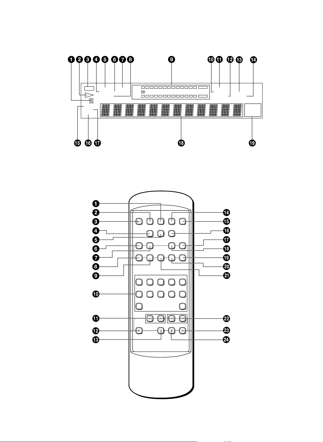
NAM ES OF BUTTONS, CONTROLS, AND INDI CATORS
FRONT PANEL (see the illustration on page 55)
1 STANDBY/ON switch (5)
2 Disc insert slot (7)
3 7 (stop) button (7)
4 8 (pause) button (7)
5 ) (eject) button (7)
6 3 (play) button (7)
REAR PANEL (see the illustration on page
1 LINE OUT jacks (4)
2 LINE IN jacks (4)
3 AC power cord (4)
4 DIGITAL OPTICAL IN jack (4)
DISPLAY (see the illustration on page
1 8 (pause) indicator (7)
2 # (play) indicator (7)
3 REC indicator (13)
4 TITLE indicator (23)
5 REPEAT indicator (10)
6 SEARCH indicator (25)
7 PGM (program) indicator (10)
8 RANDOM indicator (9)
9 Level indicator (13)
! ANALOG indicator (13)
55)
66)
E nglish
7 Remote control sensor (6)
8 Display
9 REC button (13)
! REC LEVEL control (13)
" Jog dial/4/¢ (skip)/+/– control (8, 23)
5 DIGITAL OPTICAL OUT jack (5)
6 SYSTEM CONNECTOR jack (4)
7 VOLTAGE SELECTOR switch (This selector
on the bottom of the unit.) (2) (General model
only)
" MONO indicator (13)
# A.PAUSE indicator (11)
$ DIGITAL indicator (13)
% MANUAL indicator (14)
& SINGLE indicator (8)
( REMAIN indicator (9)
) TOTAL indicator (9)
~ Multi information display
+ Sampling rate indicator
REMOTE CONTROL TRANSMITTER (see the illustration on page
1 REPEAT button (10)
2 RANDOM button (9)
3 POWER
4 REC INPUT button (13)
5 REC MODE button (16)
6 EDIT CANCEL button (17)
7 EDIT button (18)
8 PGM (program)/CHARAC (character) button
(10, 24)
9 CHECK/SPACE button (11, 24)
! Number/character buttons (8, 24)
" 1/¡ (search) buttons (8)
# REC button (13)
button (5)
/
66)
$ 7 (stop) button (7)
% AUTO PAUSE button (11)
& DISPLAY button (8)
( AUTO/MANUAL button (14)
) TITLE INPUT buttons (23)
~ TITLE SEARCH button (25)
+ ENTER button (18)
, SET button (18)
- CLEAR/DELETE button (11, 24)
. 4/¢ (skip) buttons (8)
/ 3 (play) button (7)
: 8 (pause) button (7)
E-3
GETTING STARTED
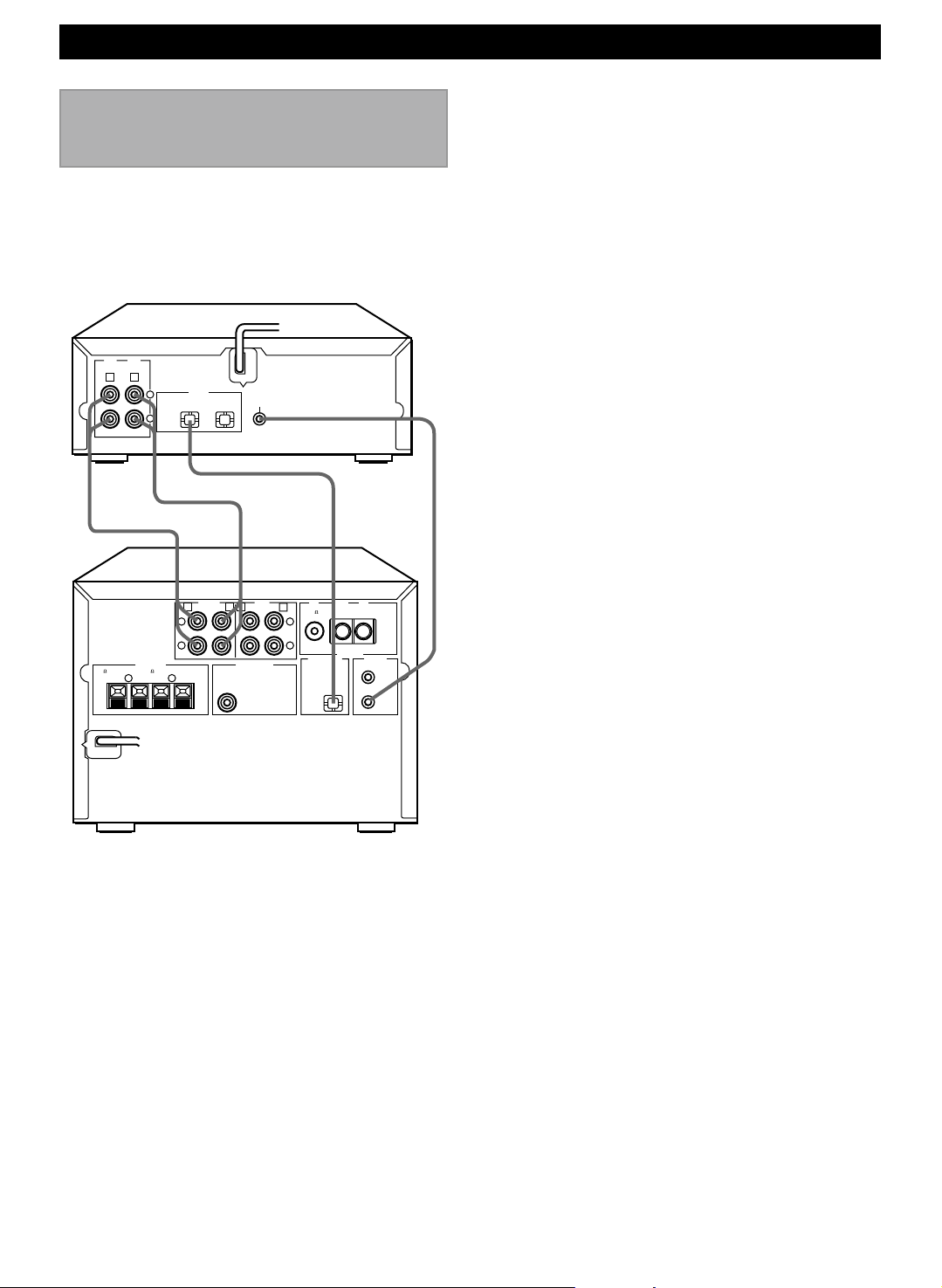
Connecting the unit to
the CRX-M5
Neve r p l u g th e A C power cord into th e w a ll
outlet until all other connections are
completed.
Follow the steps below to connect to the CRX-M5
using the supplied cords and accessories.
4
LINE
LINE
OUT
IN
C D
12
DIGITAL
6 MIN. /SPEAKER
R L
++––
L
R
IN OUT
L
1
R
6 MIN. /HAUT-PARLEUR
OPTICAL
IN INOUT OUT
AUX/MD
SYSTEM
CONNECTOR
3
TAPE
A
SUBWOOFERSPEAKERS
OUT
BC D
L
R
FM GND AM
75
UNBAL
DIGITAL OUT
CD
OPTICAL
ANTENNA
SYSTEM
CONNECTOR
TAPE
MD
1 Connect C to C, and D to D using the audio
connecting cords.
Insert the plugs into jacks of the same color.
• The two audio connecting cords are the same,
so you can connect C or D using either cord.
• The white plug of the audio connecting cord
corresponds to the left channel and the red plug
corresponds to the right channel. Make sure that
the left and right channel connections are
properly made, and that the plugs are inserted
firmly.
2 Connect the OPTICAL DIGITAL IN jack of the unit
and the DIGITAL OUT jack on the CRX-M5 with
the optical fiber cable.
3 Connect the unit and the CRX-M5 with the system
cable.
4 Connect the AC power cord to a wall outlet.
E-4
32
Playing CDsGetting Started
GETTING STARTED
Digital connections
If you have another MD deck or DAT deck, you can
make direct digital recording and enhance the sound
quality for recording by connecting the OPTICAL OUT
jack of the unit and the OPTICAL IN jack of another unit
with the optical fiber cable.
Other M D deck or DAT deck
OPTICAL
OUT IN
To the OPTICAL IN jack
Optical fiber cable (not include)
To the OPTICAL OUT jack
LINE
LINE
OUT
IN
A B
• Take off the covers of the optical fiber cable plug, the
OPTICAL DIGITAL OUT jack, and the DIGITAL IN
jack before digital connection.
* Use an optical fiber cable that conforms to EIAJ
standards. Other cables might not function
correctly.
• Be sure to replace the terminal’s cover when the
terminal on the rear panel is not being used, in
order to protect from dust.
DIGITAL
L
R
IN OUT
SYSTEM
CONNECTOR
OPTICAL
This unit
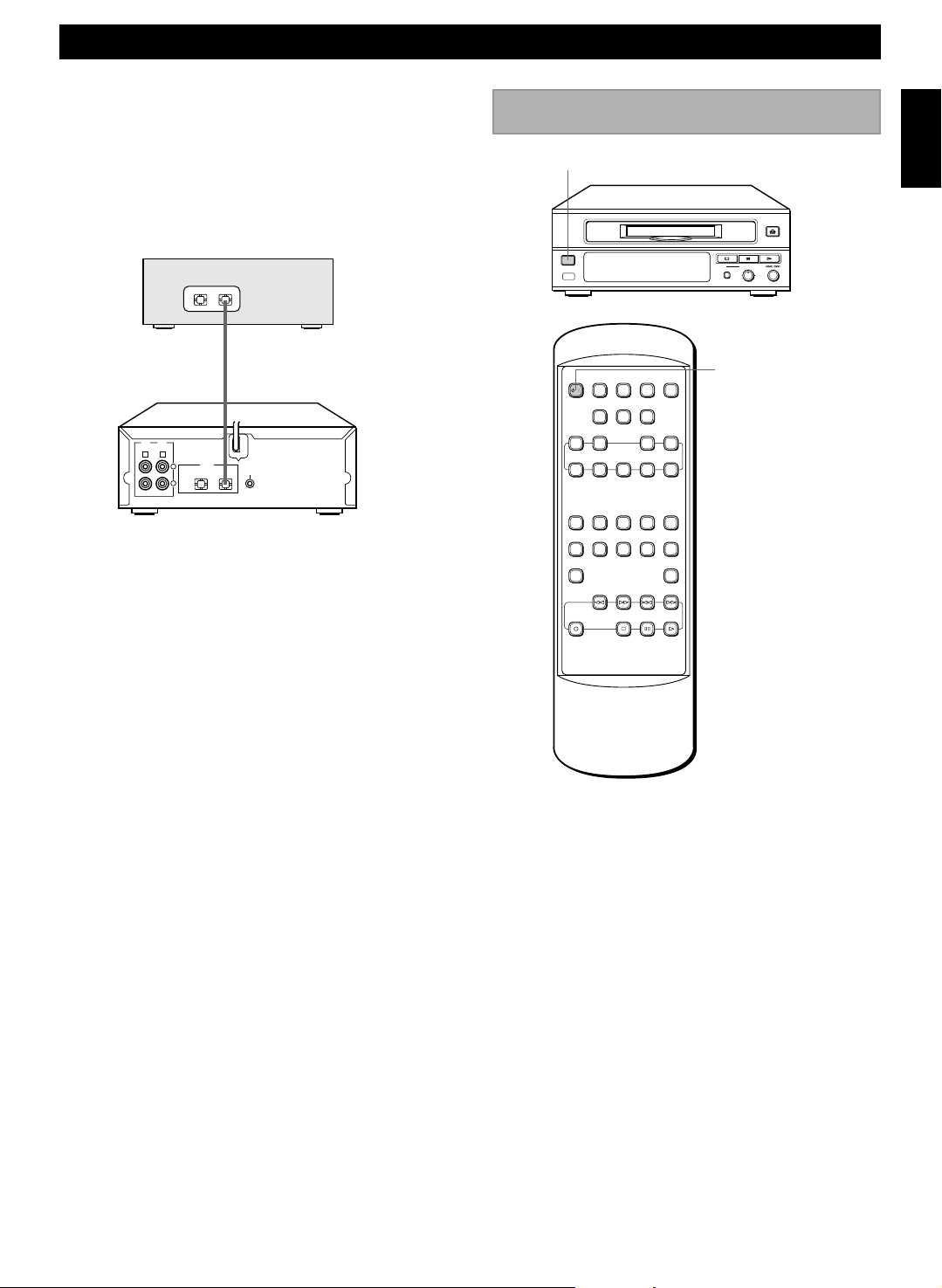
Turning on/off the unit
STANDBY/ON
STANDBY/ON
POWER RANDOM REPEAT
/
EDIT
CANCEL
PGM CHECK CLEAR ENTERSET
CHARAC SPACE DELETE
1
M N O P R S T U V Q ZW X Y
67890
& ( ) – / ’ , : ? !
+100
REC
AUTO
PAUSE DISPLAY
REC
REC
AUTO/
INPUT
MODE
MANUAL
TITLE
EDIT
SEARCH
A B C D E F J K LG H I
2345
TITLE
INPUT
+10
REC LEVEL
REC
010
POWER
– +
E nglish
After connecting the AC power cord to the wall outlet,
press the STANDBY/ON switch on the front panel or
POWER on the remote to turn on/off the unit.
E-5
GETTING STARTED
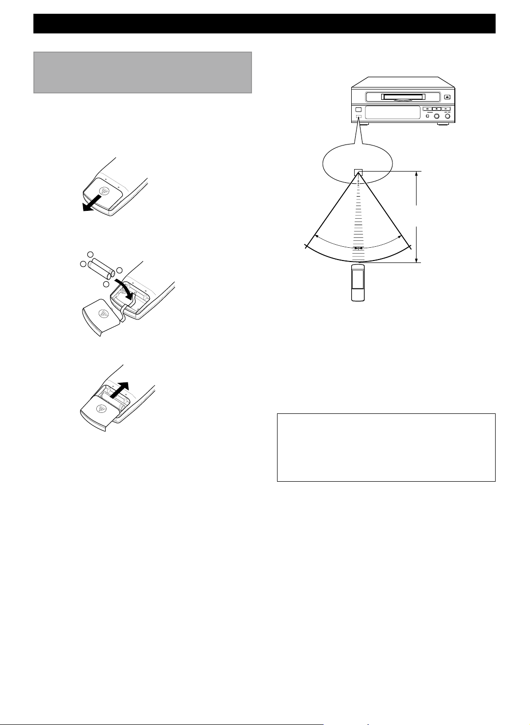
Preparing the remote
control transmitter
Remote control transmitter operation range
Loading th e batteries for t he remote control
t ransmitte r
1 Remove the battery compartment cover.
2 Insert 2 AAA size batteries into the battery
compartment.
–
+
+
–
3 Replace the battery compartment cover.
STANDBY/ON
Remote control
sensor
REC LEVEL
REC
– +
010
Within approximately
6 m (19.7 feet)
30°
30°
Notes
• There should be no large obstacles between the
remote control transmitter and the main unit.
• If the remote control sensor is directly illuminated by
strong lighting (especially an inverter type of
fluorescent lamp etc.), it might cause the remote
control transmitter not to work correctly. In this case,
reposition the main unit to avoid direct lighting.
B attery replac ement
If you find that the remote control transmitter must be
used closer to the main unit than usual, the batteries
are weak. Replace both batteries with new ones.
Notes
• Use only AAA batteries for replacement.
• Be sure the polarities are correct. (See the illustration
inside the battery compartment.)
• Remove the batteries if the remote control transmitter
will not be used for an extended period of time.
• If batteries leak, dispose of them immediately. Avoid
touching the leaked material or letting it come in
contact with clothing, etc. Clean the battery
compartment thoroughly before installing new
batteries.
E-6
Note
• This manual describes how to operate this unit by using
the remote control transmitter mainly. To operate the
unit from the front panel, use the corresponding buttons
on the front panel (see page 3).
 Loading...