

Yamaha Audio MDX-E300 User Manual

MDX-E300
OWNER’S MANUAL
MODE D’EMPLOI
BEDIENUNGSANLEITUNG
BRUKSANVISNING
MANUALE DI ISTRUZIONI
MANUAL DE INSTRUCCIONES
GEBRUIKSAANWIJZING
Minidisc Recorder
Lecteur Enregistreur de Minidisc
GB

1 To assure the finest performance, please read this
manual carefully. Keep it in a safe place for future
reference.
2 Install this unit in a well ventilated, cool, dry, clean
place away from direct sunlight, heat sources, vibration,
dust, moisture or cold. In a cabinet, allow about 2.5 cm
(1 inch) of free space all around this unit for adequate
ventilation.
3 Locate this unit away from other electrical appliances,
motors, or transformers to avoid humming sounds.
4 Do not expose this unit to sudden temperature changes
from cold to hot, nor locate this unit in an environment
with high humidity (i.e., a room with a humidifier) to
prevent condensation inside this unit, which may cause
an electrical shock, fire, damage to this unit, and/or
personal injury.
5 Avoid installing this unit in a location where foreign
objects may fall onto this unit or where this unit may be
exposed to liquid dripping or splashing. On the top of
this unit, do not place:
• Other components, as they may cause damage and/or
discoloration on the surface of this unit.
• Burning objects (i.e., candles), as they may cause fire,
damage to this unit, and/or personal injury.
• Containers with liquid in them, as they may fall, spilling
the liquid and causing an electrical shock to the user
and/or damage to this unit.
6 Do not cover this unit with a newspaper, tablecloth,
curtain, etc. in order not to obstruct heat radiation. If the
temperature inside this unit rises, it may cause fire,
damage to this unit, and/or personal injury.
7 Do not plug in this unit to a wall outlet until all
connections are complete.
8 Do not operate this unit upside-down. It may overheat,
possibly causing damage.
9 Do not use excessive force on switches, knobs and/or
cords.
10 When disconnecting the power cord from the wall
outlet, grasp the plug; do not pull the cord.
11 Do not clean this unit with chemical solvents; this might
damage the finish. Use a clean, dry cloth.
12 Use only the voltage specified on this unit. Using this
unit with a higher voltage than specified is dangerous
and may cause fire, damage to this unit, and/or personal
injury. YAMAHA will not be held responsible for any
damage resulting from use of this unit with a voltage
other than as specified.
13 To prevent damage by lightning, disconnect the power
cord from the wall outlet during an electrical storm.
14 Do not attempt to modify or fix this unit. Contact
qualified YAMAHA service personnel when any service
is needed. The cabinet should never be opened for any
reason.
15 When not planning to use this unit for long periods of
time (i.e., vacation), disconnect the AC power plug from
the wall outlet.
16 Be sure to read the “Troubleshooting” section on
common operating errors before concluding that this
unit is faulty.
CAUTION: READ THIS BEFORE OPERATING THIS UNIT
17 Before moving this unit, press STANDBY/ON to set the
unit in standby mode, then disconnect the AC power
plug from the wall outlet.
18 VOLTAGE SELECTOR (China and General models
only)
The VOLTAGE SELECTOR on the rear panel of this
unit must be set for your local main voltage BEFORE
plugging into the AC main supply. Voltages are 110/120/
220/240 V AC, 50/60 Hz.
To reduce the risk of fire or electric shock, do not
expose this appliance to rain or moisture.
The unit is not disconnected from the AC power source
as long as it is connected to the wall outlet, even if this
unit itself is turned off. This state is called the standby
mode. In this state, this unit is designed to consume a
very small quantity of power.
SPECIAL INSTRUCTIONS FOR U.K. MODEL
IMPORTANT:
The wires in the mains lead are coloured in accordance
with the following code:
Blue: NEUTRAL
Brown: LIVE
As the colours of the wires in the mains lead of this
apparatus may not correspond with the coloured
markings identifying the terminals in your plug,
proceed as follows: The wire which is coloured BLUE
must be connected to the terminal which is marked
with the letter N or coloured BLACK. The wire which
is coloured BROWN must be connected to the terminal
which is marked with the letter L or coloured RED.
Making sure that neither core is connected to the earth
terminal of the three pin plug.
For U.K. customers
If the socket outlets in the home are not suitable for the
plug supplied with this appliance, it should be cut off and
an appropriate 3 pin plug fitted. For details, refer to the
instructions described above.
Note: The plug severed from the mains lead must be
destroyed, as a plug with bared flexible cord is hazardous
if engaged in a live socket outlet.
CAUTION
Use of controls or adjustments or performance of
procedures other than those specified herein may
result in hazardous radiation exposure.

1
English
FEATURES
• MINI DISC digital audio system
• Digital optical input (2)/output
• Sampling rate converter
• EDIT function
CONTENTS
FEATURES .............................................. 1
SUPPLIED ACCESSORIES ....................... 2
NOTES ABOUT MINIDISCS .................... 2
NAMES OF BUTTONS AND CONTROLS
Front panel ............................................................ 3
Display .................................................................. 3
Remote control ..................................................... 4
GETTING STARTED
Remote control ..................................................... 5
System connections .............................................. 6
Connecting your audio system ............................. 8
PLAYBACK............................................. 9
Skipping tracks ..................................................... 9
Searching .............................................................. 9
Switching the display ......................................... 10
Random play ....................................................... 11
Repeat play ......................................................... 11
A-B repeat .......................................................... 11
Program play ...................................................... 12
RECORDING ........................................ 13
Adjusting recording levels .................................. 14
Track marking..................................................... 14
Music synchro recording .................................... 15
Setting the recording mode ................................. 15
Monitor out .........................................................16
Protecting a recorded MD .................................. 16
EDITING ............................................... 17
Erase ................................................................... 18
Move ................................................................... 19
Combine ............................................................. 19
Divide ................................................................. 20
Undo ................................................................... 20
TOC write ...........................................................20
FRA check .......................................................... 20
TITLING................................................ 21
ADDITIONAL INFORMATION
MD recorder system notes .................................. 22
Display messages................................................ 23
Troubleshooting .................................................. 24
Specifications...................................................... 25
• Synchronized recording/timer recording
by system connection
• Digital rec level control
• MDLP (Long play and recording)
2
SUPPLIED ACCESSORIES
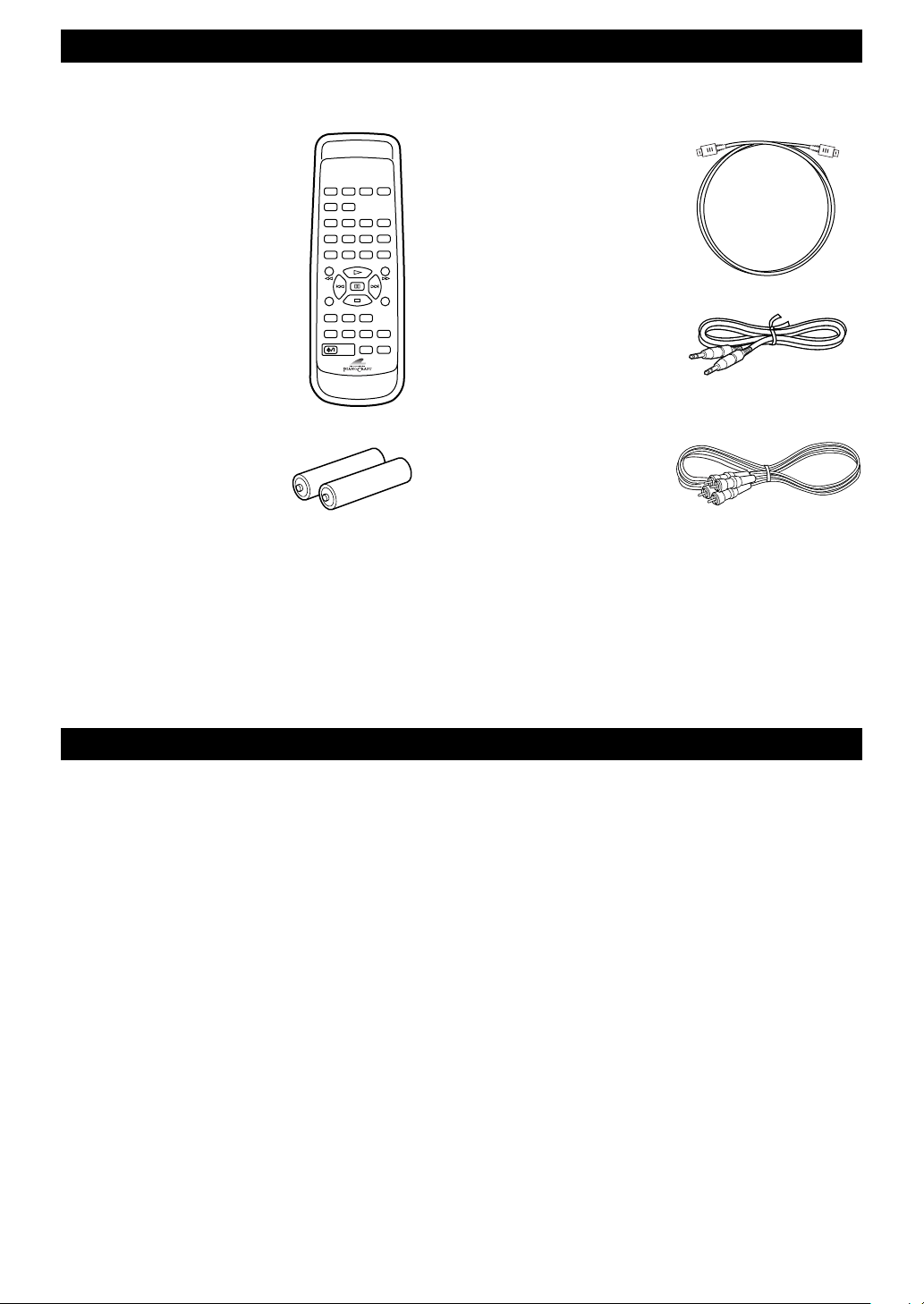
Check that the following items are included.
• Remote control
• Batteries (AA, R6, UM-3)
• Optical cable
• System control cable
• Audio pin cable
NOTES ABOUT MINIDISCS
Care of MDs
• Do not expose the MD to direct sunlight or heat sources
such as hot air ducts, nor leave it in a car parked in
direct sunlight as there can be a considerable rise in
temperature inside the car.
• Periodically remove dust and debris from the cartridge
surface by wiping it with a dry cloth.
• Because the MD itself is housed in a cartridge, you can
handle it normally without being concerned about dirt
or fingerprints. However, malfunctioning may result if
the cartridge itself is dirty or warped.
Do not open the shutter on the MD
cartridge
Trying to force the shutter open will damage the shutter.
TITLE
DELETE
SET
CANCEL ENTER
EDIT
CHAR
NUMBER
A B C D E F G H I J K L
1234
5678
90
+10 +100
A-B S/F
DISPLAY
POWER
SCROLL
M N O P Q R S T U V W X
Y Z
REC/
PAUSE
SYNC
/
SPACE
M-MARK REC MODE
INPUT
RANDOM PROGRAM
REPEAT
3
English
NAMES OF BUTTONS AND CONTROLS
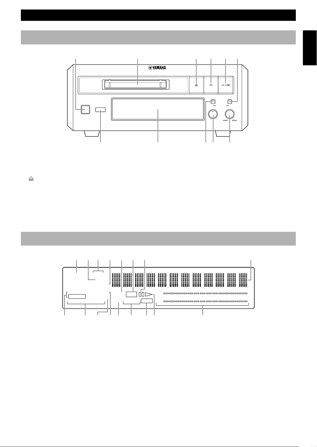
Front panel
1 STANDBY/ON (P.9)
2 Disc insertion slot (P.9)
3
(P.9)
4 & (P.9)
5 #/* (P.9)
6 REC/PAUSE (P.13)
Display
1 Input indicator (P.13)
2 TOTAL indicator (P.10)
3 DISC/TRACK indicator (P.10)
4 REMAIN indicator (P.10)
5 MANUAL indicator (P.14)
6 REC indicator (P.13)
7 Pause indicator
8 Multi information display
9 Sampling frequency indicator (P.13)
STANDBY/ON
NATURAL SOUND MINIDISC RECORDER MDX-E300
+–
INPUT
ANALOG
REC LEVEL
DIGITAL
MIN MAX
REC/PAUSE
123456
7890q
ANALOG
DIGITAL
COAX.
32 44.1 48
kHz
REPEAT
MANUAL
REC
MONO
LP2 LP4
TOC
DISC TRACK
TOTAL
REMAIN
RANDOM
PROGRAM
A-B S F
L
R
dB
–
60 30 10 6 4 2 1 0 OVER00
–– – ––––
OPT.12
qwer ty u90
1234567 8
0 REPEAT A-B/S F indicator (P.11)
q PROGRAM indicator (P.12)
w RANDOM indicator (P.11)
e MONO indicator (P.15)
r LP2/LP4 indicator (P.15)
t TOC indicator (P.17)
y Play indicator
u Recording level meter (P.14)
7 Remote control sensor (P.5)
8 Display (P.3)
9 INPUT (P.13)
0 ANALOG REC LEVEL (P.14)
q Jog dial ($ ›)/DIGITAL REC LEVEL
(P.9/P.14)
4
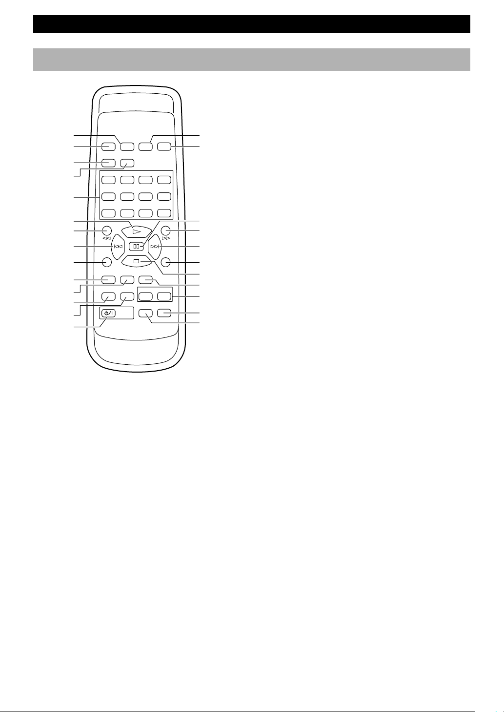
Remote control
1 DELETE/CANCEL (P.21)
2 TITLE (P.21)
3 CHAR (P.21)
4 NUMBER (P.21)
5 Numbers [Characters] (P.9/P.21)
6 # (P.9/P.14)
7 ! (P.9/P.21)
8 $ (P.9/P.21)
9 REC/PAUSE (P.13)
0 M-MARK (P.14)
q REC MODE (P.15)
w RANDOM (P.11)
e PROGRAM (P.12)
r POWER (P.9)
t SET/ENTER (P.21)
y EDIT (P.18)
u * (P.9)
i ⁄ (P.9/P.21)
o › (P.9/P.21)
p SYNC (P.15)
a & (P.9)
s INPUT (P.13)
d REPEAT A-B (P.11)
REPEAT S/F (P.11)
f SCROLL (P.10)
g DISPLAY (P.10)
NAMES OF BUTTONS AND CONTROLS
TITLE
DELETE
SET
CANCEL ENTER
EDIT
CHAR
NUMBER
A B C D E F G H I J K L
1234
5678
90
+10 +100
A-B S/F
DISPLAY
POWER
SCROLL
M N O P Q R S T U V W X
Y Z
REC/
PAUSE
SYNC
/
SPACE
M-MARK REC MODE
INPUT
RANDOM PROGRAM
REPEAT
1t
y
u
i
o
p
a
s
d
f
g
2
3
4
5
6
8
9
0
q
w
e
r
7
5
English
Remote control
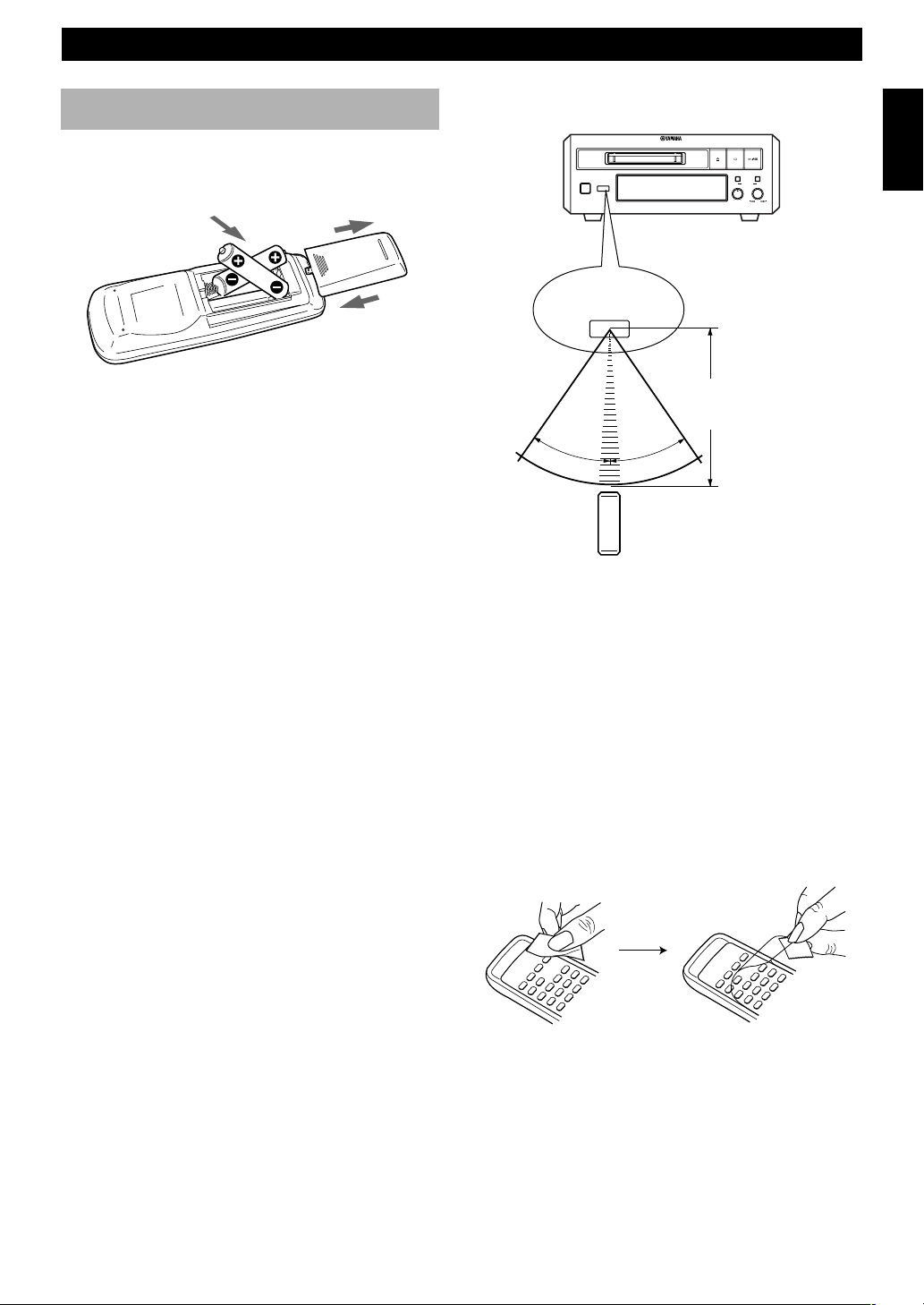
Battery installation
1 Remove the battery compartment cover.
2 Insert batteries into the battery compartment.
3 Replace the battery compartment cover.
Battery replacement
If you find that the remote control must be used closer to
the main unit than usual, the batteries are weak. Replace
batteries with new ones.
Notes
• Use only AA, R6, UM-3 batteries for replacement.
• Be sure the polarities are correct. (See the illustration inside
the battery compartment.)
• Remove the batteries if the remote control will not be used for
an extended period of time.
• If batteries leak, dispose of them immediately. Avoid touching
the leaked material or letting it come in contact with clothing,
etc. Clean the battery compartment thoroughly before
installing new batteries.
Remote control operation range
Notes
• There should be no large obstacles between the remote control
and the main unit.
• If the remote control sensor is directly illuminated by strong
lighting (especially an inverter type of fluorescent lamp, etc.),
it might cause the remote control not to work correctly. In this
case, reposition the main unit to avoid direct lighting.
Removing the protection sheet
The remote control is shipped with a protection sheet to
prevent the surface from being scratched during
transportation.
When removing the sheet, first put adhesive tape on an
edge of the remote control so that the tape sticks to the
sheet. Then peel the sheet off with the tape.
Note
• Do not scratch the remote control surface when peeling the
sheet off.
GETTING STARTED
STANDBY/ON
NATURAL SOUND MINIDISC RECORDER MDX-E300
+–
INPUT
ANALOG
REC LEVEL
DIGITAL
MIN MAX
REC/PAUSE
30°
30°
Remote control
sensor
Within approximately
6 m (20 feet)
2
1
3
TITL
E
DEL
ETE
SET
CHAR
NUMBE
R
A B C D E F G H I J K L
M N O P Q R S T U V W X
Y Z/
SPA
CE
CANCEL ENTER
EDIT
1 2 3
4
5 6 7 8
9 0
+10
+100
TITL
E
DELE
TE
SET
CH
AR
NUM
BER
A B C D
E F G
H I J K
L
M
N
O
P
Q
R
S T U V
W
X
Y
Z /
SPA
CE
CANCEL ENTER
E
DIT
1 2 3 4
5 6 7 8
9 0
+10
+1
00
6
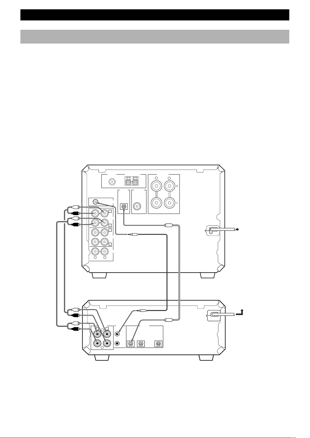
System connections
Never plug the AC power cord to the wall outlet until all connections are
completed.
• Connections should be made to the correct input/output jacks on the other component.
• Also refer to the owner’s manual supplied with the components you are connecting.
• If the placement of this unit causes noise in other equipment, such as a tuner, move them farther apart.
• The connection using the SYSTEM CONNECTOR jack allows you to control this unit as well as the connected
components of YAMAHA Piano Craft series. Make system control connections between the Piano Craft series
components using the system control cable.
To reduce the standby power consumption, connect the AC power cord of this unit to a switched AC outlet of your
receiver (Except for U.K. model).
Notes
• Before making OPTICAL connections, remove the jack cover(s).
• In order to protect the jacks from dust, be sure to attach the jack covers when the optical jacks are not being used.
Connecting CRX-E300
GETTING STARTED
ANALOG DIGITAL
OPTICAL
SYSTEM
CONNECTOR
IN
L
D
OUT
1IN2 OUT
R
C
MD
TAPE
IN
OUT
IN
IN
OUT
AUX
D
A
B
LR
C
OUT
6
Ω
MIN. /SPEAKER
OUT
DIGITAL
SUBWOOFER
OPTICAL
SPEAKERS
RL
FM ANT
GND – AM ANT
75Ω UNBAL.
SYSTEM CONNECTOR
This unit (MDX-E300)
CD receiver (CRX-E300)
Audio pin
cables
(included)
Optical cable
(included)
System control cable
(included)
To wall outlet
To CRX-E300
Notes
• The ANALOG OUT jacks on this unit are marked Ç and the ANALOG IN jacks are marked Î. When connecting this unit to
CRX-E300 whose jacks are marked Å, ı, Ç and Î, connect this unit’s ANALOG OUT jacks to the input jacks marked Ç and connect
this unit’s ANALOG IN jacks to the output jacks marked Î on the rear panel of CRX-E300.
• The SYSTEM CONNECTOR jack should be connected to the SYSTEM CONNECTOR jack on CRX-E300.
• For digital recording, the DIGITAL OPTICAL 1 IN jack should be connected to the DIGITAL OPTICAL OUT jack on CRX-E300.
7
English
ANALOG DIGITAL
OPTICAL
SYSTEM
CONNECTOR
IN
L
D
OUT
1IN2 OUT
R
C
FM ANT
75Ω UNBAL.
IN
IN
IN
IN
OUT
OUT
6Ω MIN./SPEAKER
SPEAKERS
SUBWOOFER
OUT
SYSTEM
CONNECTOR
GND
AM
ANT
TAPE
CD
AUX
MD
R
L
R L
+
–
A
B
E
C
D
ANALOG DIGITAL
OPTICAL
SYSTEM
CONNECTOR
L
OUT
OUT
R
E
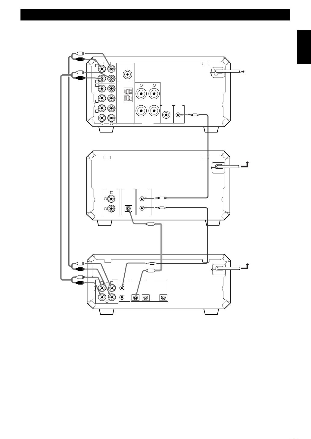
GETTING STARTED
To wall outlet
Notes
• The ANALOG OUT jacks on this unit are marked Ç and the ANALOG IN jacks are marked Î. When connecting this unit to RX-E400
whose jacks are marked Å, ı, Ç, Î and ‰, connect this unit’s ANALOG OUT jacks to the input jacks marked Ç and connect this
unit’s ANALOG IN jacks to the output jacks marked Î on the rear panel of RX-E400.
• The SYSTEM CONNECTOR jack should be connected to the SYSTEM CONNECTOR jack on CDX-E400.
• For digital recording, the DIGITAL OPTICAL 1 IN jack should be connected to the DIGITAL OPTICAL OUT jack on CDX-E400.
Connecting RX-E400 and CDX-E400
CD player (CDX-E400)
This unit (MDX-E300)
Receiver (RX-E400)
To RX-E400
Optical cable
(included)
System control cable
(included)
Audio pin cables
(included)
System control cable
To RX-E400
 Loading...