

Page 1
I/O cards
for
ANALOG INPUT BOX
ANALOG OUTPUT BOX
MIC/LINE INPUT CARD LMY2-MLAB, LMY4-MLF
AD CARD LMY4-AD
DA CARD LMY4-DA
hank you for choosing the Yamaha input card for the analog input box AI8, and the Yamaha output card for the analog
T
output box AO8.
Be sure to ask an authorized Yamaha service engineer to install the cards. Do not install the cards yourself.
The connecting screw also functions as the ground. Secure the screw tightly.
の度はヤマハアナログインプットボックス A I8用インプットカード、アナログアウトプ ットボックスA O 8用アウトプットカードを お 買 上 げ い た だき、
ここ
ありが とうござ い ま す 。
カードの取付けは、必ずヤマハサービスエンジニアにご依頼ください 。お客様ご自身では行なわないでください。
接続ネジはアース兼用ですのでしっかり締めてあるか確認してください。
■ LMY2-MLAB
This is a two-channel analog input card. Set the input level in the
range of –68 dB to +10 dB.
You can install up to eight cards in the analog input box AI8.
PM1D system software prior to V1.70 recognizes this card as
LMY2-ML. However, the card will function properly.
2チャンネルのアナログ入力カードで す。入力レベルは− 68dB 〜 +10dB
の範囲で設定します。
アナログインプットボ ック スA I8に8枚まで装着できます。
PM 1D V 1.70より前のシステムソフトウェア では、カード名が「LM Y 2-M L」
と表示されますが 正しく動作します。
Input
Terminals Impedance Nominal
CH1A, CH1B
CH2A, CH2B
* 0 dBu is referenced to 0.775 Vrms. ** 1=GND, 2=HOT, 3=COLD *** The GAIN control level displayed on the CS1D.
+48VDC (phantom power) is individually supplied to each input connectors. AD Conversion: 24 bit linear +4 bit floating, 128 times oversampling.
+4 8V D C(ファンタム 電 源 )が各入力端子にそれぞれ供給されます。A D コンバージョン:2 4 ビ ットリニ ア + 4 ビットフ ローテ ィング、1 28倍オーバーサンプリング
GAIN***
–68 dB
+10 dB
Actual Load For Use With
3 kΩ
50–600 Ω Mics
& 600 Ω Lines
When the indicator is lit in orange,
channel B is selected. When the indicator
is turned off, channel A is selected.
点灯時(オレンジ)はチャンネルB が選択、
消灯時はチャンネルA が選択
Input Level
Nominal Max. Before Clip
–68 dBu (309 µV)* –54 dBu (775 µV)*
+10 dBu (2.45 V)* +24 dBu (12.3 V)*
The green LED lights up
at 34 dB before clipping.
クリッピング手前34dB で
緑色LE D が点灯
Connector
XLR-3-31 type
(Balanced)**
■ LMY4-MLF
This is a four-channel analog input card. Set the input level in the
range of –68 dB to +10 dB.
You can install up to eight cards in the analog input box AI8.
PM1D system software prior to V1.70 recognizes this card as
“Unknown” and cannot communicate with it. Be sure to use this
card with PM1D V1.70 or higher.
4チャンネルのアナログ入力カードで す。入力レベルは− 68dB 〜 +10dB
の範囲で設定します。
アナログインプットボ ック スA I8に8枚まで装着できます。
PM 1D V 1.70より前のシステムソフトウェア で は、カード名が「U nknow n」と
表示され、お使いいただけませ ん。必ずP M 1D V 1.70以上のシステムでお
使いください 。
Input
Terminals Impedance Nominal
CH1–4
* 0 dBu is referenced to 0.775 Vrms. ** 1=GND, 2=HOT, 3=COLD *** The GAIN control level displayed on the CS1D.
+48VDC (phantom power) is individually supplied to each input connectors. AD Conversion: 24 bit linear, 128 times oversampling.
+4 8V D C(ファンタム 電 源 )が各入力端子にそれぞれ供給されます。A D コンバージョン:2 4 ビ ットリニ ア、1 28倍オーバーサンプリング
GAIN***
–68 dB
+10 dB
Actual Load For Use With
3 kΩ
50–600 Ω Mics
& 600 Ω Lines
The green LED lights up at 34 dB before clipping.
クリッピング手前34dB で緑色LE D が点灯
Input Level
Nominal Max. Before Clip
–68 dBu (309 µV)* –54 dBu (775 µV)*
+10 dBu (2.45 V)* +24 dBu (12.3 V)*
Connector
XLR-3-31 type
(Balanced)**
Page 2
■ LMY4-AD
U.R.G., Pro Audio & Digital Musical Instrument Division, Yamaha Corporation
© 2003 Yamaha Corporation
WC62510 312IPAPx.x-01A0
Printed in Japan
ヤマハマニュアルライブラリー
Ya maha Manual Library
http://www2.yamaha.co.jp/manual/english/
http://www2.yamaha.co.jp/manual/japan/
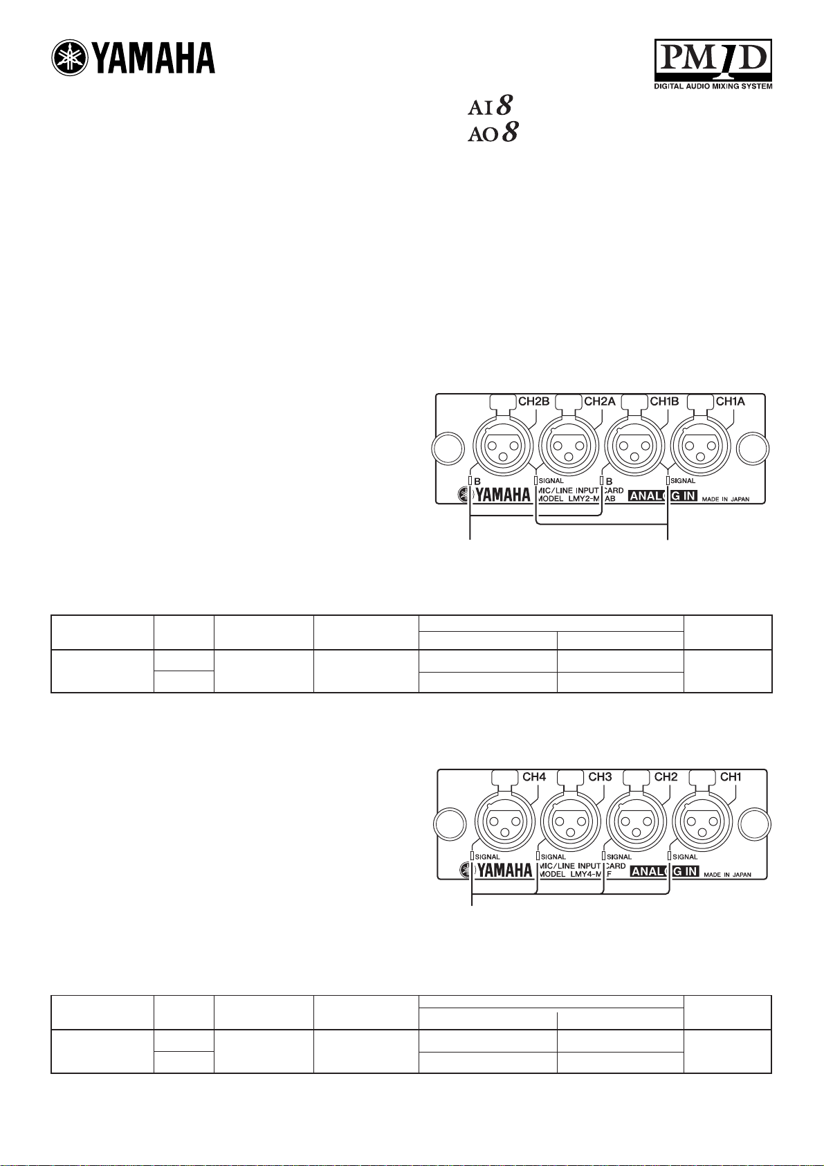
This is a four-channel analog input card.
You can install up to eight cards in the analog input box AI8.
4チャンネルのアナログ入力カードです。
アナログインプットボ ック スA I8に8枚まで装着できます。
SIGNAL
CH4
SIGNAL
AD CARD
MODEL LMY4-AD
CH3 CH2 CH1
SIGNAL
SIGNAL
ANALOG IN
The green LED lights up at 34 dB before clipping.
クリッピング手前34dB で緑色LE D が点灯
Input Actual Load For Use With
Terminals Impedance Nominal
Nominal Max. Before Clip
Input Level
Connector
CH 1–4 10 kΩ 600 Ω Lines +10 dBu (2.45 V)* +24 dBu (12.3 V)* XLR-3-31 type (Balanced)**
* 0 dBu is referenced to 0.775 Vrms. ** 1=GND, 2=HOT, 3=COLD
AD Conversion: 24 bit linear +4 bit floating, 128 times oversampling.
A D コンバージョン:24ビットリニ ア + 4 ビットフ ロ ー ティング、128倍オーバーサンプリング
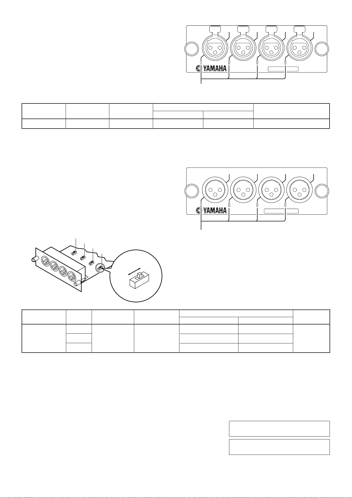
■ LMY4-DA
CH4 CH3 CH2 CH1
This is a four-channel analog output card. Set the maximum output
level in the range of +15 dB to +24 dB. The factory default setting is
+24 dB.
You can install up to eight cards in the analog output box AO8.
4チャンネルのアナログ出 力カードです。最大出力レベルは+15dB〜
+24dB の範囲で設定します。工場出荷時は+24dB です。
SIGNAL SIGNAL SIGNAL SIGNAL
DA CARD
MODEL LMY4-DA
ANALOG OUT
アナログアウトプ ットボ ックスA O 8に8枚まで装着できます。
4
3
2
1
+15dB
+24dB
+24dB
+18dB
+18dB
+15dB
The green LED lights up at 34 dB before clipping.
クリッピング手前34dB で緑色LE D が点灯
Output GAIN Actual Source For Use With
Terminals switch Impedance Nominal
+24 dB +10 dBu (2.45 V)* +24 dBu (12.3 V)*
CH 1–4 +18 dB 150 Ω 600 Ω Lines +4 dBu (1.23 V)* +18 dBu (6.16 V)*
+15 dB +1 dBu (870 mV)* +15 dBu (4.36 V)*
* 0 dBu is referenced to 0.775 Vrms. ** 1=GND, 2=HOT, 3=COLD
DA Conversion: 24 bit linear +3 bit floating, 128 times oversampling.
D A コンバージョン:24ビットリニ ア + 3 ビットフ ロ ー ティング、128倍オーバーサンプリング
For European Model
Purchaser/User Information specified in EN55103-1 and EN55103-2.
Conformed Environment: E1, E2, E3 and E4
Output Level
Nominal Max. Before Clip
Connector
XLR-3-32 type
(Balanced)**
Page 3

documentation manual, user maintenance, brochure, user reference, pdf manual
This file has been downloaded from:
User Manual and User Guide for many equipments like mobile phones, photo cameras, monther board, monitors, software, tv, dvd, and othes..
Manual users, user manuals, user guide manual, owners manual, instruction manual, manual owner, manual owner's, manual guide,
manual operation, operating manual, user's manual, operating instructions, manual operators, manual operator, manual product,
 Loading...