

Page 1

Page 2

SPECIAL MESSAGE SECTION
This product utilizes batteries or an external power supply (adapter). DO
NOT connect this product to any power supply or adapter other than one
described in the manual, on the name plate, or specifically recommended by Yamaha.
WARNING:
walk on, trip over ,or roll anything over power or connecting cords of any
kind. The use of an extension cord is not recommended! If you must use
an extension cord, the minimum wire size for a 25’ cord (or less ) is 18
AWG. NOTE: The smaller the AWG number ,the larger the current handling capacity. For longer extension cords, consult a local electrician.
This product should be used only with the components supplied or; a
cart, rack, or stand that is recommended by Yamaha. If a cart, etc., is
used, please observe all safety markings and instructions that accompany the accessory product.
Do not place this product in a position where anyone could
SPECIFICATIONS SUBJECT TO CHANGE:
The information contained in this manual is believed to be correct at the
time of printing. However, Yamaha reserves the right to change or modify
any of the specifications without notice or obligation to update existing
units.
This product, either alone or in combination with an amplifier and headphones or speaker/s, may be capable of producing sound levels that
could cause permanent hearing loss. DO NOT operate for long periods
of time at a high volume level or at a level that is uncomfortable. If you
experience any hearing loss or ringing in the ears, you should consult an
audiologist.
IMPORTANT: The louder the sound, the shorter the time period before
damage occurs.
Some Yamaha products may have benches and / or accessory mounting fixtures that are either supplied with the product or as optional
accessories. Some of these items are designed to be dealer assembled
or installed. Please make sure that benches are stable and any optional
fixtures (where applicable) are well secured BEFORE using.
Benches supplied by Yamaha are designed for seating only. No other
uses are recommended.
NOTICE:
Service charges incurred due to a lack of knowledge relating to how a
function or effect works (when the unit is operating as designed) are not
covered by the manufacturer’s warranty, and are therefore the owners
responsibility. Please study this manual carefully and consult your dealer
before requesting service.
ENVIRONMENTAL ISSUES:
Yamaha strives to produce products that are both user safe and environmentally friendly. We sincerely believe that our products and the production methods used to produce them, meet these goals. In keeping with
both the letter and the spirit of the law, we want you to be aware of the
following:
Battery Notice:
This product MAY contain a small non-rechargeable battery which (if
applicable) is soldered in place. The average life span of this type of battery is approximately five years. When replacement becomes necessary,
contact a qualified service representative to perform the replacement.
This product may also use “household” type batteries. Some of these
may be rechargeable. Make sure that the battery being charged is a
rechargeable type and that the charger is intended for the battery being
charged.
When installing batteries, do not mix batteries with new, or with batteries
of a different type. Batteries MUST be installed correctly. Mismatches or
incorrect installation may result in overheating and battery case rupture.
Warning:
Do not attempt to disassemble, or incinerate any battery. Keep all batteries away from children. Dispose of used batteries promptly and as regulated by the laws in your area. Note: Check with any retailer of
household type batteries in your area for battery disposal information.
Disposal Notice:
Should this product become damaged beyond repair, or for some reason
its useful life is considered to be at an end, please observe all local,
state, and federal regulations that relate to the disposal of products that
contain lead, batteries, plastics, etc. If your dealer is unable to assist
you, please contact Yamaha directly.
NAME PLATE LOCATION:
The name plate is located on the top panel of the product. The name
plate lists the product’s model number, power requirements, and other
information. The serial number is located on the name plate. Please
record the model number, serial number, and date of purchase in the
spaces provided below, and keep this manual as a permanent record of
your purchase.
Model
Serial No.
Purchase Date
92-BP
(others)
PLEASE KEEP THIS MANUAL
Page 3
Water warning
Fire warning
If you notice any abnormality
Location
PRECAUTIONS
PLEASE READ CAREFULLY BEFORE PROCEEDING
* Please keep this manual in a safe place for future reference.
WARNING
Always follow the basic precautions listed below to avoid the possibility of serious injury or even death from
electrical shock, short-circuiting, damages, fire or other hazards. These precautions include, but are not limited to,
the following:
Power supply/AC power adaptor
• Only use the voltage specified as correct for the instrument. The required
voltage is printed on the name plate of the instrument.
• Use the specified adaptor (PA-5D or an equivalent recommended by Yamaha)
only. Using the wrong adaptor can result in damage to the instrument or
overheating.
• Check the electric plug periodically and remove any dirt or dust which may
have accumulated on it.
• Do not place the AC adaptor cord near heat sources such as heaters or
radiators, and do not excessively bend or otherwise damage the cord, place
heavy objects on it, or place it in a position where anyone could walk on, trip
over, or roll anything over it.
Do not open
• Do not open the instrument or attempt to disassemble the internal parts or
modify them in any way. The instrument contains no user-serviceable parts. If
it should appear to be malfunctioning, discontinue use immediately and have
it inspected by qualified Yamaha service personnel.
• Do not expose the instrument to rain, use it near water or in damp or wet
conditions, or place containers on it containing liquids which might spill into
any openings.
• Never insert or remove an electric plug with wet hands.
• Do not put burning items, such as candles, on the unit.
A burning item may fall over and cause a fire.
• If the AC adaptor cord or plug becomes frayed or damaged, or if there is a
sudden loss of sound during use of the instrument, or if any unusual smells or
smoke should appear to be caused by it, immediately turn off the power
switch, disconnect the adaptor plug from the outlet, and have the instrument
inspected by qualified Yamaha service personnel.
English
CAUTION
Always follow the basic precautions listed below to avoid the possibility of physical injury to you or others, or
damage to the instrument or other property. These precautions include, but are not limited to, the following:
Power supply/AC power adaptor
• When removing the electric plug from the instrument or an outlet, always hold
the plug itself and not the cord.
• Unplug the AC power adaptor when not using the instrument, or during
electrical storms.
• Do not connect the instrument to an electrical outlet using a multipleconnector. Doing so can result in lower sound quality, or possibly cause
overheating in the outlet.
• Do not expose the instrument to excessive dust or vibrations, or extreme cold
or heat (such as in direct sunlight, near a heater, or in a car during the day) to
prevent the possibility of panel disfiguration or damage to the internal
components.
• Do not use the instrument in the vicinity of a TV, radio, stereo equipment,
mobile phone, or other electric devices. Otherwise, the instrument, TV, or
radio may generate noise.
• Do not place the instrument in an unstable position where it might
accidentally fall over.
• Before moving the instrument, remove all connected adaptor and other cables.
• Use only the rack specified for the instrument. When attaching the rack, use
the provided screws only. Failure to do so could cause damage to the internal
components or result in the instrument falling over.
(3)-7
1/2
3
Page 4
Handling caution
Connections
• Before connecting the instrument to other electronic components, turn off the
power for all components. Before turning the power on or off for all
components, set all volume levels to minimum. Also, be sure to set the
volumes of all components at their minimum levels and gradually raise the
volume controls while playing the instrument to set the desired listening level.
Maintenance
• When cleaning the instrument, use a soft, dry cloth. Do not use paint thinners,
solvents, cleaning fluids, or chemical-impregnated wiping cloths.
English
Yamaha cannot be held responsible for damage caused by improper use or modifications to the instrument, or data that is lost or destroyed.
Always turn the power off when the instrument is not in use.
Even when the power switch is in the “STANDBY” position, electricity is still flowing to the instrument at the minimum level. When you are not using the instrument for a
long time, make sure you unplug the AC power adaptor from the wall AC outlet.
• Do not insert a finger or hand in any gaps on the instrument.
• Never insert or drop paper, metallic, or other objects into the gaps on the
panel. If this happens, turn off the power immediately and unplug the power
cord from the AC outlet. Then have the instrument inspected by qualified
Yamaha service personnel.
• Do not place vinyl, plastic or rubber objects on the instrument, since this
might discolor the panel or keyboard.
• Do not rest your weight on, or place heavy objects on the instrument, and do
not use excessive force on the buttons, switches or connectors.
• Do not operate the instrument for a long period of time at a high or
uncomfortable volume level, since this can cause permanent hearing loss. If
you experience any hearing loss or ringing in the ears, consult a physician.
(3)-7
2/2
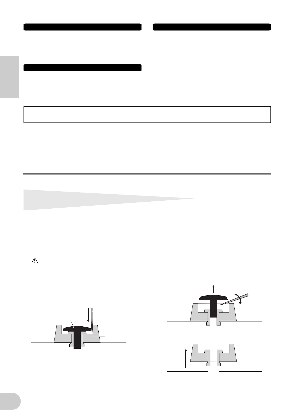
Removing rubber stoppers for rack mount installation
The i88X has four removable rubber stoppers. If the i88X does not fit in your rack mount cabinet
because the stoppers hit against another device, remove the stoppers as described below.
Before removing the stoppers, make sure you have a sharp, thin tool — such as a safety pin or straightened paper clip.
CAUTION
Do not use any tool that easily snaps or bends, such as a toothpick or thin wire.
1. Turn the i88X upside down.
2. Insert the tool between the rubber stopper
and the plastic rivet (as shown).
3. Pull the rivet up and out of the panel.
Sharp tool
Rivet
Rubber stopper
4
4. Pull out the rubber stoppers.
To re-attach the removed stoppers, reverse the
procedure above, inserting the rivets perpendicularly.
Page 5
•
•
•
•
•
•
•
•
•
•
•
•
Introduction
Thank you for purchasing the Yamaha i88X Audio/MIDI Interface.
Connecting the i88X to a computer expands music production environments that utilize an audio
sequencer on the computer.
The i88X supports mLAN, a digital music network based on the IEEE1394 high performance serial
bus and data protocol. The i88X makes it easy to construct sophisticated networks for IEEE1394
audio and MIDI signals without having to re-configure complicated cabling, as was necessary on
earlier conventional systems.
In order to take full advantage of the i88X’s functionality, please read this manual carefully. After
reading this manual, please keep it available for future reference.
Package Contents
English
i88X unit
Tools for i88X/mLAN16E (CD-ROM)
Plug-in Effect (CD-ROM)
mLAN cable (IEEE1394 cable) (6-pin to 6-pin)
AC Adaptpr: PA-5D
Owner’s Manual (this document)
Tools for i88X/mLAN16E Installation Guide
User’s Card (containing the serial number for the included Plug-in software effects)
About the included CD-ROM
The i88X is shipped with a CD-ROM that contains software that is useful when used in conjunction with the i88X. This software includes drivers that are required to connect the i88X to a computer. It also includes software that enables you to route audio and MIDI signals between mLAN
devices and plug-in effects. For more information, refer to the separate “Tools for i88X/mLAN16E
Installation Guide” and the software online manuals.
Yamaha is not responsible for damage caused by improper use or modifications to the
device or for data that is lost or destroyed.
The illustrations and LCD screens shown in this Owner’s Manual are for instructional purposes
only and may appear somewhat different from those on your device.
MIDI is a registered trademark of the Association of Musical Electronics Industry (AMEI).
mLAN is a trademark of Yamaha Corporation.
Company and product names in this Owner’s Manual are the trademarks or registered trade-
marks of their respective owners.
5
Page 6

■
■
•
Features
Fast data transfer via mLAN
Connecting the i88X to a computer and other mLAN devices via IEEE1394 (FireWire/i.LINK) cables
enables you to transfer multi-channel audio data and multi-port MIDI signals to and from a computer-based DAW (Digital Audio Workstation) and connected mLAN devices (at a transfer rate of
400Mbps [S400]).
Up to 18 audio channel I/O
English
The i88X features two MIC/LINE inputs and six LINE inputs. Inputs 1 and 2 feature two sonically
transparent mic preamps (derived from DM2000) and phantom power, and accept both XLR
and TRS phone plugs. Inputs 3-8 accept TRS phone plugs (pages 8 and 11).
•
Input 1 also features a HI-Z (high impedance) jack to connect high-impedance instruments, such
as guitar or bass (page 8).
•
The Insert I/O jacks enable you to connect an external effects processor (page 11).
•
The i88X also features a sampling rate converter that supports sampling frequencies from
44.1 kHz through 96 kHz. It also features coaxial DIGITAL STEREO IN and OUT jacks and the
optical IN and OUT jacks that are switchable between STEREO and ADAT.
•
The MIDI IN and OUT ports enable you to connect external MIDI devices in the mLAN system
(page 11).
•
The i88X can process up to 18-channel input and output data when running at a sampling frequency of 48 kHz or 44.1 kHz, and up to 14-channel input and output data when running at a
sampling frequency of 96 kHz or 88.2 kHz.
■
Audio Characteristics
•
Compatible sampling frequencies: 44.1 kHz, 48 kHz, 88.2 kHz, 96 kHz
•
Linear 24-bit, 128-times (at a sampling frequency of 48 kHz or 44.1 kHz) or 64-times (at a sampling frequency of 96 kHz or 88.2 kHz) oversampling A/D and D/A converters
•
Frequency response: 20 Hz – 20 kHz, Standard dynamic range: 110 dB
■
Direct Monitoring Function
•
Enables you to monitor the sound being recorded to the DAW without latency (sound delay)
(page 17).
■
Integrated Package Containing Plug-in Effects
•
Four VST/AU plug-in effects, including equalizer, vocal and mastering effects, etc.
Table of Contents
Removing rubber stoppers for rack mount installation....................................................... 4
Introduction .......................................................................................................................... 5
Package Contents.................................................................................................................. 5
Features ................................................................................................................................. 6
Fundamentals of mLAN......................................................................................................... 7
Operational Flow for Sound Output..................................................................................... 7
Names and Functions............................................................................................................ 8
Front Panel.................................................................................................................... 8
Rear Panel .................................................................................................................... 11
Turning the Power to the i88X and Connected Devices On and Off ................................. 12
Connecting External Devices ............................................................................................... 13
Connecting Musical Instruments and Microphones and Adjusting the Input Level.......... 16
Direct Monitoring ................................................................................................................ 17
System Examples.................................................................................................................. 18
Making mLAN Connections ................................................................................................. 20
LED Indicators ...................................................................................................................... 21
Troubleshooting................................................................................................................... 22
Specifications ....................................................................................................................... 25
6
Page 7

Fundamentals of mLAN
mLAN is a digital network for music that was developed based on IEEE1394, an industry-standard
high-performance data communications protocol.
Digital music environments that do not feature mLAN require dozens of cables for various devices
and purposes, including MIDI cables and audio cables to route MIDI and audio signals. If you wish
to make changes to such systems, you must physically disconnect and re-connect these cables.
For example, adding another synthesizer to a system requires two MIDI cables and two or more
cables for audio (for stereo equipment). Making the appropriate connections may require special
knowledge of inputs, outputs, stereo settings, and perhaps connector impedance.
The larger the system, the more complicated and expensive these connections become, increasing
the likelihood of errors and difficulties. It takes time and effort to investigate such errors and their
underlying causes. You may have already experienced the unpleasantness of tracking various cables
through a spider’s web of connections.
English
mLAN simplifies cable connections by using only one type of IEEE1394 cable, thus enabling you to
configure extremely sophisticated systems. There is no need to re-patch cables to change routings
of MIDI and audio signals between mLAN devices.
Operational Flow for Sound Output
1. Install Tools for i88X/mLAN16E.
........... See “Installing the Software” in the Installation Guide.
2. Connect the computer and mLAN devices using the IEEE1394 cables.
........... See page 13.
3. Turn on mLAN Manager (Windows only).
........... See “Confirming the installation” in the Installation Guide.
4. To connect a computer to a single mLAN device directly, first start mLAN Auto Connector.
To connect a computer to multiple mLAN devices, start mLAN Graphic Patchbay.
........... See page 20
5. Configure connections in mLAN Auto Connector or mLAN Graphic Patchbay.
........... Using Auto Connector: See “Connecting a Computer to an mLAN device via
mLAN” in the Installation Guide.
........... Using Graphic Patchbay: See “mLAN Connection Settings” in the Graphic Patch-
bay Online Manual.
6. Specify the audio and MIDI inputs and outputs, following the owner’s manual for your
DAW, audio sequencer and connected devices.
For subsequent steps, refer to the owner’s manual for the software and connected devices.
NOTE
In this manual, setting up audio, MIDI, and wordclock routings is referred as “mLAN connection.”
7
Page 8
Names and Functions
NOTE
Numbers indicated to the left of the names (
numbers indicated in the block diagram on back cover page.
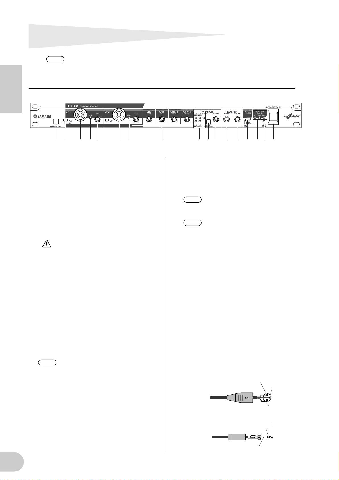
Front Panel
English
1 2 3 4 3 4 5 76 8 9 0 A CB D5
1 [PHANTOM +48V] switch
This switch supplies +48 V phantom power to
XLR and TRS phone compatible INPUT jacks 1
and 2 (3). Note that phantom power will not
be supplied if you have connected an external
device to the INPUT 1 and 2 TRS phone jacks
(3). Turn this switch on if you are connecting a
condenser microphone that requires external
+48 V power to INPUT jack 1 or 2 (3). When
the switch is turned on, the switch indicator
lights up.
• Be sure to turn this switch off if you
connect a device that does not require
an external power supply to the INPUT
1 or 2 XLR jack. Otherwise, phantom
power will be supplied to the device,
possibly causing damage to the
device.
• If you connect a device that requires
an external power supply, first connect
the device to an XLR connector, then
turn on the phantom power.
• When phantom power is turned on,
power will be supplied to both INPUT
jacks 1 and 2.
• Phantom power is not supplied to TRS
phone connectors.
NOTE
2 [(HI-Z)/LINE/MIC] switch
This switch enables you to select high-impedance input, mic input, or line input for XLR and
TRS phone compatible INPUT jacks 1 and 2
3).
(
HI-Z: Use this setting to connect a high-
If the [HI-Z/LINE/MIC] switch (2) is
set to HI-Z, phantom power is not supplied to INPUT jack 1 (3).
impedance musical instrument, such
as a guitar with passive pickups or a
bass guitar.
1
-
5
,
7
-
A
,
E
-
K, and M) correspond the
LINE: Use this setting to connect a line-level
instrument, such as a synthesizer, keyboard, or audio equipment.
MIC: Use this setting to connect a mic-level
device.
NOTE
NOTE
Select HI-Z, LINE, or MIC for INPUT
jack 1. Select LINE or MIC for INPUT
jack 2.
When the [HI-Z/LINE/MIC] switch is
set to HI-Z, phantom power is not supplied to INPUT jack 1 (3).
3 XLR/TRS Phone Compatible INPUT 1 and
2 jacks
These balanced input jacks accept both XLR-331 and TRS phone (1/4") plugs and can be used
for high-impedance, line or mic inputs. You can
also connect musical instruments with unbalanced outputs, such as a synthesizer or rhythm
machine. Setting the [HI-Z/LINE/MIC] switch
(2) appropriately enables you to connect a
high-impedance instrument, line-out instrument or microphone to INPUT jack 1. Setting
the [LINE/MIC] switch (2) appropriately
enables you to connect a line-out instrument or
microphone to INPUT jack 2.
Nominal input levels:
MIC: –60 dBu to –16 dBu
LINE: –34 dBu to +10 dBu
HI-Z: –56 dBu to –12 dBu
1 (Ground)
Male XLR plug
1/4"TRS phone plug
Ring (Cold)
3 (Cold)
2 (Hot)
Tip (Hot)
Sleeve (Ground)
8
Page 9
4 [PEAK] indicators
A [PEAK] indicator lights up red if the input signal that has passed through the [GAIN] control
(5) reaches a level 3 dB below the clipping
point. In order to record at the optimal level,
adjust the [GAIN] control (5) so that this indicator flickers briefly when you play at your loudest level.
5 [GAIN] controls
These controls enable you to adjust the input
sensitivity (head amp gain) of INPUT jacks 1, 2,
3, 4, 5/6 and 7/8. (page 16)
Setting range:
Ch 1 & 2
MIC: –16 dBu to –60 dBu
LINE: +10 dBu to –34 dBu
HI-Z,: –12 dBu to –56 dBu
Ch 3–8 +10 dBu to –20 dBu
6 MONITOR [1/2 (44k)] - [7/8 (96k)] indi-
cators
When the monitoring channels selected via the
[SELECT] switch (7) output signals, the corresponding [1/2] - [7/8] indicators in the MONITOR section light up red.
When you press and hold down the [SELECT]
switch for one second or longer, the indicator
for the current operating sampling frequency
(44k, 48k, 88k, or 96k) flashes red.
NOTE
The [44k] indicator represents a sam-
pling frequency of 44.1 kHz, and the
[88k] indicator represents a sampling
frequency of 88.2 kHz.
7 MONITOR [SELECT] switch
This switch enables you to select a monitoring
channel that outputs signals from the MASTER
OUT L and R jacks on the rear panel (page 17).
Press the switch briefly (less than one second)
repeatedly to select monitoring channels in the
following sequence:
Off → CH1/2 → CH3/4 → CH5/6 → CH7/8 →
DIGITAL STEREO → Off
The MONITOR indicator (6) for the selected
channels lights up.
Also, when you press and hold down this switch
for one second or longer, the MONITOR indicator for the current operating sampling frequency flashes red.
NOTE
NOTE
You cannot route a signal input from the
ADAT NORMAL/DOUBLE jack to a
monitoring channel.
The monitoring channel selection is
reset to Off when you turn the power
to the i88X off and then back on.
8 [MONITOR VOLUME] control
This control adjusts the signal volume level of
the monitoring channel selected via the
[SELECT] switch (7). The monitoring signal is
output from the OUTPUT/MASTER 1/L and 2/R
jacks and MASTER PHONES jack (page 17).
9 MASTER PHONES jack
You can connect a set of stereo headphones to
this stereo phone jack. The signals output from
the OUTPUT/MASTER 1/L and 2/R jacks are also
output from this jack.
0 [MASTER VOLUME] control
This control adjusts the level of the signals output from the OUTPUT/MASTER 1/L and 2/R
jacks.
NOTE
To output mLAN INPUTS audio level
signals from the OUTPUT/MASTER 1/
L and 2/R jacks (G) at line level
(+4 dBu), turn the [MASTER VOLUME] control all the way to the right.
The signals will be output at the same
level as those output from the OUTPUT 3-8 jacks.
A [OPTICAL SELECT] switch
This switch enables you to select the function of
the OPTICAL IN and OUT jacks on the rear
panel. For more information, refer to “About
the OPTICAL SELECT switch, MASTER CLOCK
indicator, and wordclock master” on page 10.
ADAT DOUBLE:
Select this option for a high sampling rate
(88.2 kHz or 96 kHz). The OPTICAL IN and
OUT jacks function as ADAT IN and OUT jacks
that receive and transmit digital audio signals
of up to four channels at the same time. A single optical cable combines eight-channel,
44.1 kHz or 48 kHz digital audio signals into
four-channel, 88.2 kHz or 96 kHz digital audio
signals.
ADAT NORMAL:
Select this option for a normal sampling rate
(44.1 kHz or 48 kHz). The OPTICAL IN and
OUT jacks function as ADAT IN and OUT jacks
that receive and transmit up to eight-channel
digital audio data. This is the standard ADAT
format.
DIGITAL:
The OPTICAL IN and OUT jacks function as a
digital stereo input and output.
NOTE
NOTE
If you select DIGITAL, the COAXIAL IN
jack is disabled.
Before you select ADAT DOUBLE,
make sure that your ADAT-compatible
device supports ADAT DOUBLE
mode.
B MASTER CLOCK indicators
These indicators light up to indicate the wordclock to which the i88X is locking. For more
information, refer to “About the OPTICAL
SELECT switch, MASTER CLOCK indicator, and
English
9
Page 10
wordclock master” on page 10. You can select
the sampling frequency using mLAN Auto Connector or mLAN Graphic Patchbay (page 20).
INT: The i88X uses the internal clock at
44.1 kHz.
ADAT: The i88X uses the incoming ADAT sig-
nal as the master clock.
mLAN: The i88X uses the incoming mLAN
signal as the master clock.
Lit green: The i88X locks to the word-
English
Flashing green: The i88X is not locking to the
C [mLAN ACTIVE] indicator
This indicator lights up when the i88X is operating.
The indicator turns off when an error occurs
during an mLAN operation.
When you click the [ID] button in mLAN Auto
Connector or mLAN Graphic Patchbay
clock master.
wordclock master.
(page 20) to identify the corresponding mLAN
device in the network, the indicator flashes.
NOTE
The indicator also lights up if an mLAN
cable is not connected to the unit.
D [STANDBY/ON] switch
This switch turns the power to the unit on
or off (Standby).
CAUTION
Be sure to follow the procedures described in
“Turning the Power to the i88X and Connected
Devices On and Off” on page 12 when you
turn the power to the i88X on or off.
Even when the switch is in the STANDBY position, a small amount of electricity is still flowing
to the unit. When you do not plan to use the
i88X for an extended period of time, be sure to
unplug the AC power adapter from the AC outlet.
■ About the OPTICAL SELECT Switch, MASTER CLOCK Indicators, and Wordclock
The function of the OPTICAL IN and OUT jacks (J) specified by the [OPTICAL SELECT] switch (7), and
which MASTER CLOCK indicator (B) will light up, varies depending on which mLAN device in the mLAN
network is being used as the wordclock master.
1. When the wordclock master in an mLAN
network is an mLAN device other than
the computer and i88X (that is, when the
i88X is using the incoming mLAN signal
as the master clock):
MASTER CLOCK indicators
The [mLAN] indicator lights up.
[OPTICAL SELECT] switch
DIGITAL:
The OPTICAL IN and OUT jacks function as a
digital stereo input and output.
ADAT NORMAL or ADAT DOUBLE:
The sampling frequency in the mLAN network
determines the operating mode (NORMAL or
DOUBLE). You can select either mode when
the OPTICAL IN and OUT jacks are used as the
ADAT input and output.
2. When the i88X is referencing the incoming ADAT master clock signal and the
i88X has been specified as the clock master in the mLAN network (that is, when
the i88X is using the signal from ADAT as
the master clock):
MASTER CLOCK indicators
The [ADAT] indicator lights up.
[OPTICAL SELECT] switch
DIGITAL:
The OPTICAL IN and OUT jacks function as a
digital stereo input and output, but the IN jack
is unable to receive the ADAT wordclock signal. Therefore, the i88X automatically switches
to its internal clock running at 44.1 kHz. (Refer
to Case 3.)
ADAT NORMAL:
The OPTICAL IN and OUT jacks function in
ADAT NORMAL mode.
ADAT DOUBLE:
The OPTICAL IN and OUT jacks function in
ADAT DOUBLE mode.
3. When the i88X is not receiving the correct wordclock:
MASTER CLOCK indicators
The [INT] indicator lights up, and the i88X references its internal clock running at 44.1 kHz.
In Case 1, the [mLAN] indicator also lights up.
In Case 2, the [ADAT] indicator also lights up.
[OPTICAL SELECT] switch
DIGITAL:
The OPTICAL IN jack functions as the digital
stereo input. In this case, you can still monitor
analog inputs (from INPUTs 1-8) and digital
stereo input (from OPTICAL IN). Therefore,
you can monitor the sound from a musical
instrument or microphone connected to the
i88X without running the computer.
ADAT NORMAL or ADAT DOUBLE:
ADAT signals are unavailable, although you
can still monitor analog input (from INPUTs 1-
8).
10
Page 11
Rear Panel
21
M HK GJ IL
DC IN
F E
DIGITAL
STEREO
OUTIN IN
OPTICAL
DIGITAL STEREO
COAXIAL
876543
876543
INPUT
(BAL)
21
2/ R 1/ L
INSERT I/O
OUTPUT / MASTER
+4dB(BAL)
MIDI
OUT
English
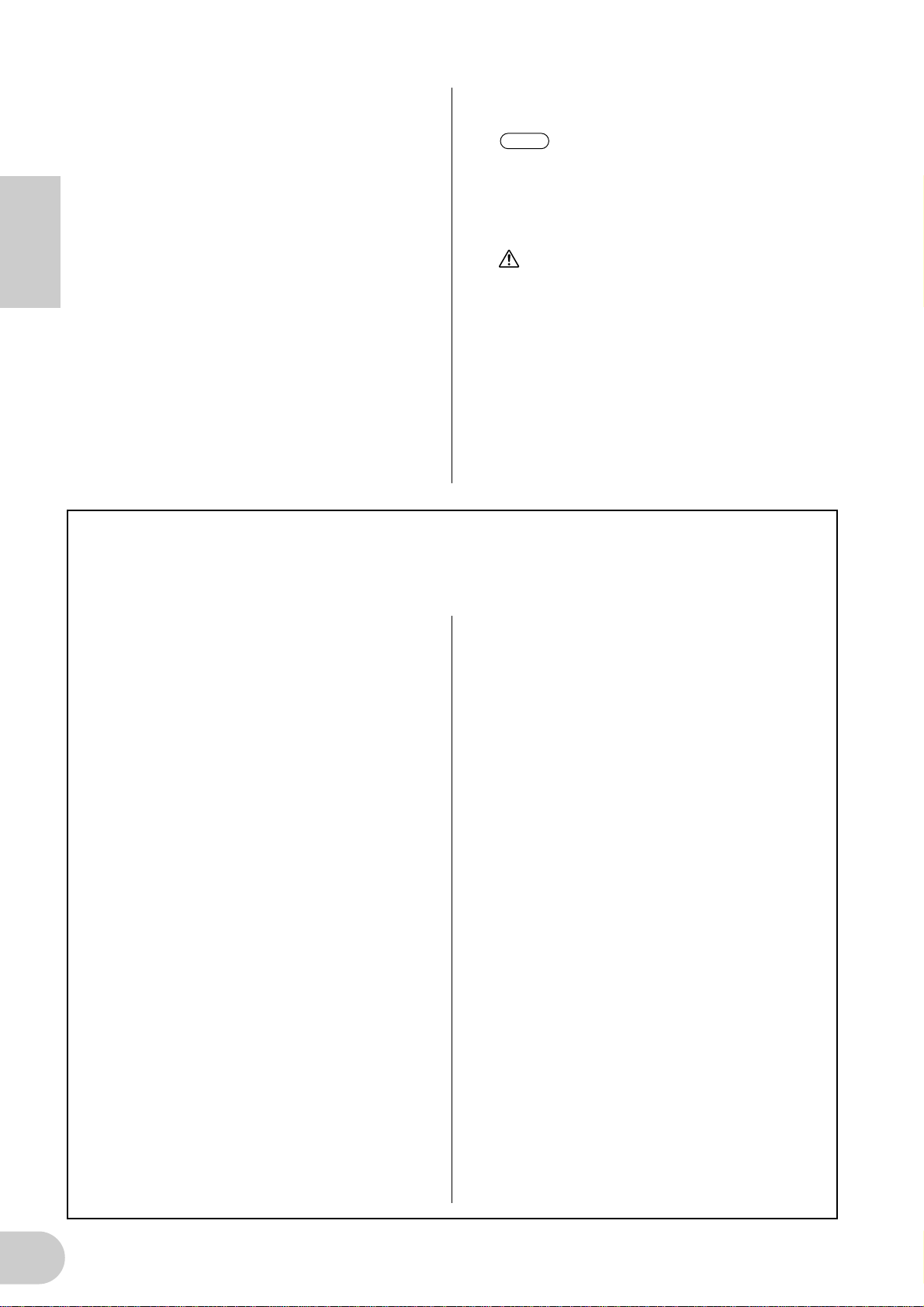
E INSERT I/O 1 & 2 (TRS phone) jacks
These unbalanced TRS phone-type 1/4" connectors are used for channel insert ins and outs. Use
a split cable to insert an external effects processor to INPUT 1 & 2 (3) on the front panel.
INSERT I/O 1 corresponds to INPUT 1, and
INSERT I/O 2 to INPUT 2.
The pin configuration is shown below.
To external processor input
To INSERT I/O
Tip
Tip
Sleeve
Sleeve
Ring
To external processor output
F INPUT 3-8 (TRS phone) jacks
These are TRS phone type 1/4" input jacks (balanced). The nominal input level is –20 dBu
through +10 dBu. You can also connect devices
such as synthesizers or rhythm machines with
unbalanced outputs here.
G OUTPUT 1 & 2 / MASTER OUT L & R (TRS
phone) jacks
These TRS phone type 1/4" output jacks (balanced) output an audio analog signal, which is
the combination of mLAN input channels 1 & 2,
and audio monitoring output selected via the
[SELECT] (7) switch on the front panel. The
nominal output level is +4 dBu (pages 16 and
17).
H OUTPUT 3-8 (TRS phone) jacks
These TRS phone type 1/4" output jacks (balanced) output audio analog signals from mLAN
input channels 3-8 respectively. The nominal
output level is +4 dBu.
I DIGITAL STEREO COAXIAL IN & OUT
jacks
These coaxial jacks (RCA pin connectors) input
and output IEC-60958 consumer format digital
audio signals. Connect these jacks to the stereo
input and output of a DAT recorder, MD
recorder, etc., using RCA pin cables for digital
audio.
J OPTICAL IN & OUT jacks
These optical jacks input and output digital stereo or ADAT audio signals. Use the [OPTICAL
SELECT] (A) switch on the front panel to select
DIGITAL STEREO, ADAT NORMAL, or ADAT
DOUBLE mode.
NOTE
The coaxial and optical digital stereo
input jacks feature a built-in sampling
rate converter (SRC), which enables
audio signals at different sampling frequencies to be input from connected
devices.
K MIDI IN & OUT ports
Connect MIDI equipment here. These ports
enable you to transmit MIDI messages between
a computer or mLAN devices in an mLAN network and a MIDI instrument connected to the
i88X.
L DC IN terminal
Connect the included AC adapter (PA-5D) here.
WARNING
Be sure to use the included adapter. Using an
AC adapter other than the PA-5D may cause
damage to the i88X, and may even pose a serious electrical shock hazard. Connect the
adapter to an AC outlet of the specified voltage.
M mLAN 1 & 2 connectors
These 6-pin IEEE1394 connectors enable you to
connect the i88X to an mLAN device or
IEEE1394-compatible (FireWire/i.Link) device.
The operation is identical regardless of which
connector is used (mLAN 1 or mLAN 2). If the
target device has a 4-pin connector, use a commercially available 4-pin to 6-pin IEEE1394
cable. Avoid creating a connection loop
(page 23) when connecting the devices.
NOTE
Yamaha recommends that you use an
IEEE1394 cable with a length of 4.5
meters or less.
11
Page 12
Turning the Power to the i88X and Connected Devices On and Off
Preparation
Before you connect the power adapter, make
sure that the i88X [STANDBY/ON] switch is set
to STANDBY (Off).
English
A Connect the plug of the power adapter
(PA-5D) to the DC IN terminal on the
rear panel of the i88X.
B Plug in the AC cable to an appropriate
AC outlet.
Rear panel
MIDI
DC IN
DC IN
1
terminal
NOTE
WARNING
• Be sure to use the included adapter. Using an
AC adapter other than the PA-5D may cause
damage to the i88X, and may even pose a
serious electrical shock hazard.
• Connect the adapter to an AC outlet of the
specified voltage.
OUT
Follow this procedure in reverse order
to disconnect the power adapter.
IN
Power adapter
PA-5D
2
AC outlet
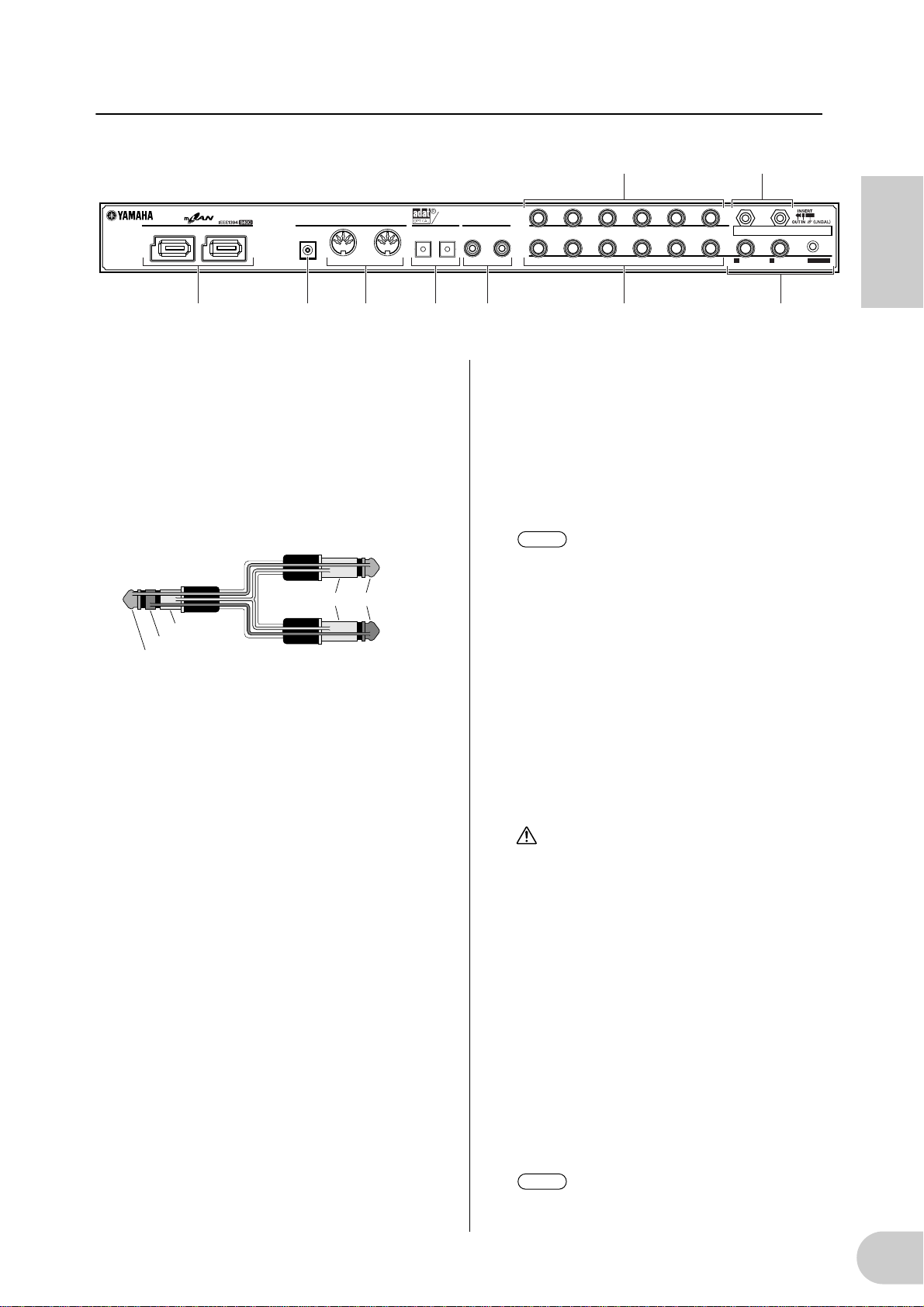
1. Turn on the power to the external
devices, such as a sound source or effects
processor connected to the input and
output of the i88X.
2Turn on the
power to
the i88X.
3Turn on the power to
the external audio
equipment connected
to the output of the
i88X. (mixer → amplifier)
NOTE
After you turn on the power to the i88X
again, restart the DAW.
To turn off the power to the devices,
first lower the volume of the audio
equipment, then turn off the power in
the reverse sequence.
Turning on the power to the i88X
POWER
ON!!
12
CAUTION
Even when the [STANDBY/ON] switch is in the
STANDBY position, a small amount of electricity is still flowing to the unit. When you do not
plan to use the i88X for an extended period of
time, be sure to unplug the AC power adapter
from the AC outlet.
Sequence of turning on and off the
power to the connected devices
After you connect the i88X and external
devices (page 13), make sure that the volume
setting on the i88X and external audio equipment is lowered to minimum, then turn on the
power to the devices in the following
sequence.
NOTE
Install mLAN Driver (for Windows)
while the power to the i88X remains off.
(See the separate Installation Guide.)
CAUTION
To protect your speakers, before you turn the
power to the i88X on or off, lower the volume
setting on the i88X and connected audio
equipment.
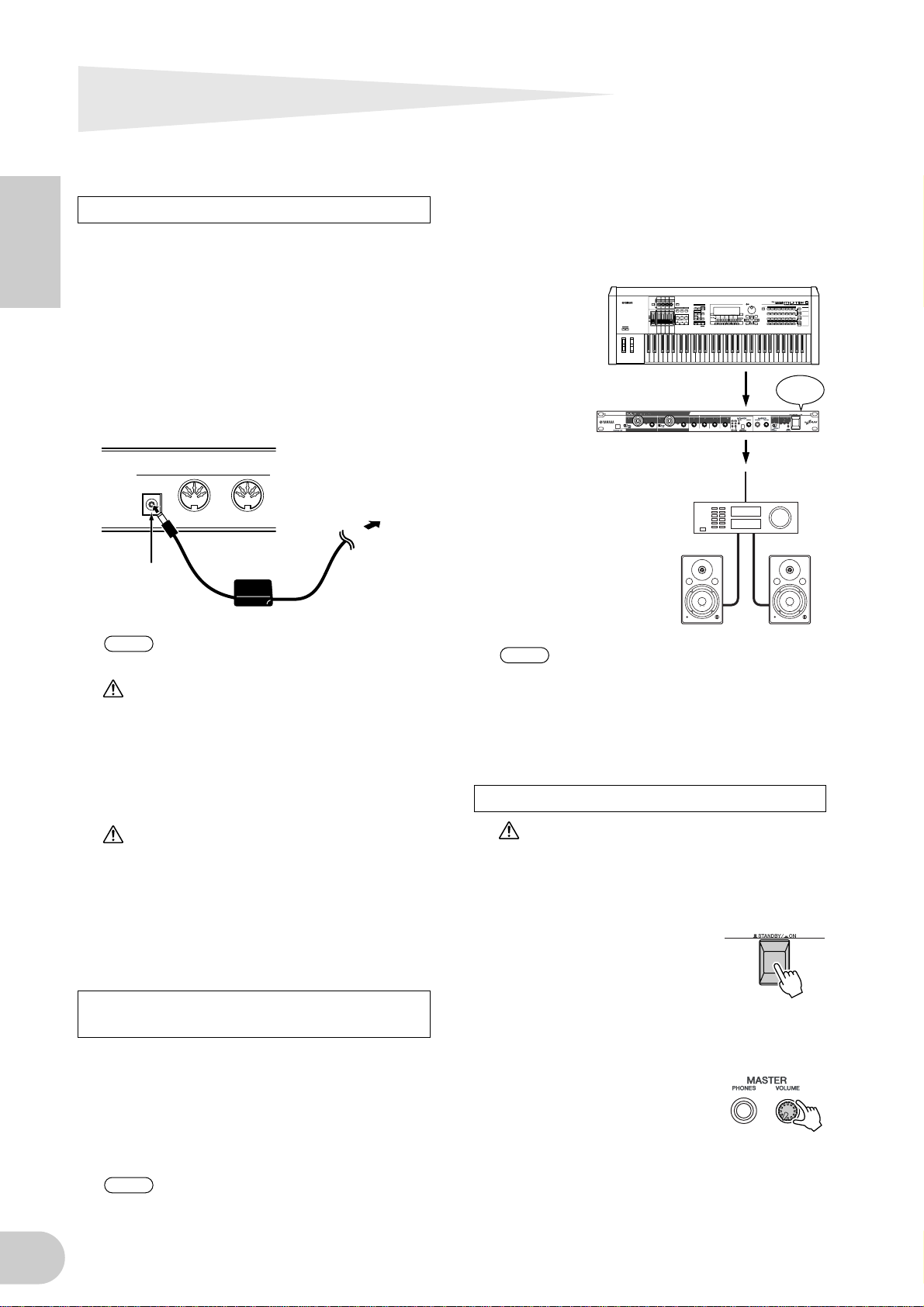
A Press the i88X [STANDBY/
ON] switch to turn on the
power to the unit.
B Raise the volume of the amplifier to an
appropriate level.
C Set the i88X [GAIN] con-
trols, [MONITOR VOLUME]
control, and [MASTER VOLUME] control to an appropriate level.
Page 13
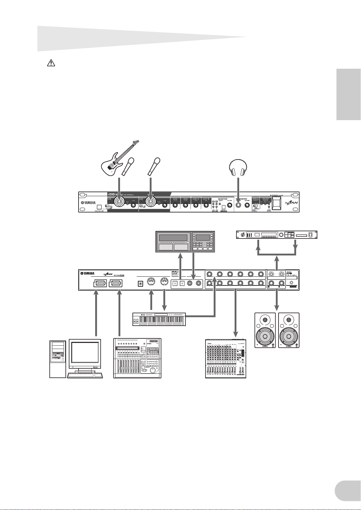
Connecting External Devices
CAUTION
Before you connect external devices to the i88X, turn off the power to all devices. Also, before you turn on
or off the power to the devices, lower the volume setting on all connected devices to minimum. Otherwise,
electrical shock or damage to the devices may result.
The following diagram illustrates a typical connection example. Refer to this diagram to connect
microphones, musical instruments, a computer, and other external devicves.
Electric guitar/
Bass/Microphone
21
CD recorder/
ADAT-compatible mixer
DIGITAL
STEREO
OUTIN IN
OPTICAL
DIGITAL STEREO
COAXIAL
MIDI
DC IN
OUT
HeadphonesMicrophone
Effects processor
88
876543
876543
INPUT
(BAL)
21
2/ R 1/ L
INSERT I/O
OUTPUT / MASTER
+4dB(BAL)
English
IEEE1394-compatible
computer
Synthesizer/Tone generator
mLAN device
such as 01X
Analog mixer
VOL
Monitor system
VOL
13
Page 14
Wordclocks
NOTE
NOTE
In a system that features multiple digitally-connected devices, all digital devices must be synchronized when digital audio signals are transferred from one device to another.
Even if the devices use matching sampling frequencies, if their audio processing timing is not
synchronized, they might not receive signals correctly, and audible noise, glitches or clicks may
occur. Synchronization is achieved using a wordclock (a clock signal that synchronizes all digital
audio signals in a system).
In a typical digital audio system, one device operates as the wordclock “master” and transmits a
English
wordclock signal. The other devices operate as wordclock “slaves,” synchronizing to the wordclock master.
To connect the i88X to external devices via mLAN, in mLAN Auto Connector or mLAN Graphic
Patchbay, select a device to be the master, then set the other devices as slaves. The i88X can
operate at a sampling frequency of 44.1 kHz, 48 kHz, 88.2 kHz or 96 kHz as either the wordclock
master or slave.
Using the i88X as the wordclock master in an mLAN network
(Using an ADAT-compatible device as the wordclock master in an mLAN network)
1. On the ADAT-compatible device connected to the i88X, specify the ADAT-compatible
device as the wordclock master.
2. Set the [OPTICAL SELECT] switch on the front panel to ADAT DOUBLE or ADAT NORMAL
(page 10).
3. In mLAN Auto Connector or mLAN Graphic Patchbay, assign the i88X as the wordclock
master in the mLAN network.
Using the i88X as the wordclock slave in an mLAN network
In mLAN Auto Connector or mLAN Graphic Patchbay, assign an mLAN device other than the
computer or i88X as the wordclock master.
Use an ADAT-compatible device or digital device (if it is connected to the i88X) to assign
the device as a wordclock slave.
For information on setting the sampling frequency and wordclock, refer to the Installation Guide,
or to the mLAN Graphic Patchbay Online Manual, or the owner’s manual for your ADAT-compatible device.
For information on system requirements and settings for making mLAN connections, refer to
the separate Installation Guide and mLAN Graphic Patchbay Online Manual.
Saving mLAN connection settings to the corresponding mLAN device
When you make mLAN connections on the computer, the connection settings will be automatically saved in the corresponding mLAN devices. Therefore, if you used mLAN Graphic Patchbay
to configure a network that excludes a computer, the next time you use the network, you will be
able to activate the network just by turning on the power to the network’s mLAN devices (without starting the computer).
14
Page 15

About connections with external devices when using the i88X with a computer
When using audio devices, musical instruments and computers at the same time, there is bound to
be some noise in the system, the amount of which depends on the connections. Knowing how to
minimize noise is extremely important when designing and setting up a studio.
As advanced as the i88X is, it too is susceptible to noise. Various types of noise may be generated
and recorded to your audio sequencer, depending on the power sources/grounding scheme and
how the various devices are connected.
There is no ideal way to completely eliminate such noise. However, one can decrease noise by isolating the cause and applying a suitable remedy. Below are a couple of examples that may apply.
• High-pitched buzzing or whirring operation noise in the computer
This is caused by operation noise of the computer leaking to other devices through the mLAN
cable or audio cable, and may be caused by improper grounding of the power source.
• Low humming noise
Noise of this type is generally due to improper grounding of the power source.
English
NOTE
The noise may differ depending on the circumstances (specifications of each device and locations of use).
If problems like these happen, try the following measures to minimize the noise.
NOTE
If the noise disappears when turning down the volume of the i88X and/or if the noise persists
even when disconnecting the mLAN cable or turning off the computer, other reasons for the
noise are likely. Refer to the Troubleshooting section in the Owner’s Manual.
1. Use balanced cable connections when connecting analog audio.
By using proper balanced connections, you can minimize the noise.
NOTE
This may have no effect depending on the specifications of the connected device.
■ Recommended Cables
i88X Inputs
Outputs of connected devices / i88X inputs (balanced) i88X inputs
Balanced
(mixer, mic preamp, etc.)
Unbalanced
(MIDI tone generator, etc.)
TRS 1/4" phone / XLR ↔ TRS phone / XLR balanced cable Ch. 1-2
TRS 1/4" phone / XLR ↔ TRS phone balanced cable Ch. 3-8
Unbalanced 1/4" phone ↔ TRS phone / XLR balanced cable Ch. 1-2
Unbalanced 1/4" phone ↔ TRS phone balanced cable Ch. 3-8
i88X Outputs
i88X outputs (OUTPUT1-OUTPUT8) / Inputs of connected devices (balanced)
Balanced
Balanced TRS 1/4" phone ↔ TRS phone / XLR balanced cable —
2. Insert a conventional direct box (passive, with transformer and ground lift switch) for connecting the audio (analog) cable.
NOTE
Example:
You may want to use several direct boxes when connecting multiple devices.
OUTPUT 1/2 of i88X – [direct box] – powered speaker
Synthesizer – [direct box] – i88X
3. Changing the power source for each device.
WARNING
Attempting this remedy is extremely dangerous and may result in electric shock. It should be done only by
qualified, experienced personnel. Contact your nearest Yamaha representative or an authorized distributor (see the last page of the Owner’s Manual).
—
15
Page 16
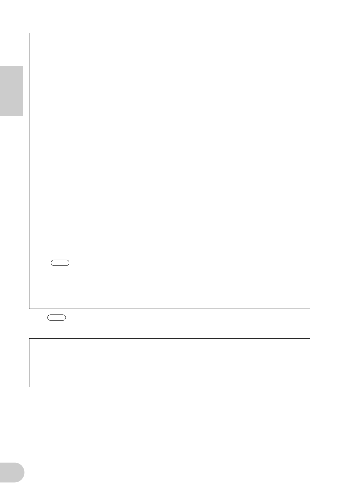
Connecting Musical Instruments and
NOTE
NOTE
Microphones and Adjusting the Input Level
Signals input at INPUT 1-8 jacks are routed to mLAN output channels 1-8 respectively. If you have
selected any pair from channels 1/2 through 7/8 for monitor output, you can monitor the corresponding input signals from MASTER L & R and MASTER PHONES (page 17).
This section describes connecting musical instruments and microphones to the INPUT 1-8 jacks and
adjusting the level of input signals.
English
ANALOG
INPUTS
1, 2, 3/4,
5/6, 7/8
GAIN
INSERT I/O
(Only Ch 1 & 2)
mLAN
OUTPUTS
MONITOR
MONITOR
SELECT
mLAN INPUTS
3-8
(from DAW output)(to DAW output)
mLAN INPUTS
1, 2
(from DAW master output)
VOLUME
MASTER
VOLUME
ANALOG
OUTPUTS
3-8
PHONES
ANALOG
OUTPUTS
1/L, 2/R
1. Turn the [MASTER VOLUME] control and the [MONITOR VOLUME] control all the way to
the minimum (rotate the controls counter-clockwise until the knob will not turn further).
To connect devices to INPUT 1 & 2, set the [(HI-Z)/LINE/MIC] switch to a setting that is appropriate for the connected devices (page 8).
You can insert an effects processor via the INSERT I/O jacks into analog input channels 1 and
2 (INPUT 1 & 2).
2. Connect the musical instruments and microphones to the INPUT 1-8 jacks.
3. Adjust the [GAIN] control for the INPUT jacks to which you connected the musical instruments and microphones.
4. Adjust the [MASTER VOLUME] control and the [MONITOR VOLUME] control.
INPUT 1 & 2 jacks:
In order to record at the optimal level, adjust the [GAIN] controls so that the [PEAK] indicator for
each input flickers briefly when you play at your loudest level.
INPUT 3 - 8 jacks
Observe the input level meters of your DAW or audio sequencer while adjusting the [GAIN] controls
to raise the level to a point just before the signal starts clipping.
16
Page 17
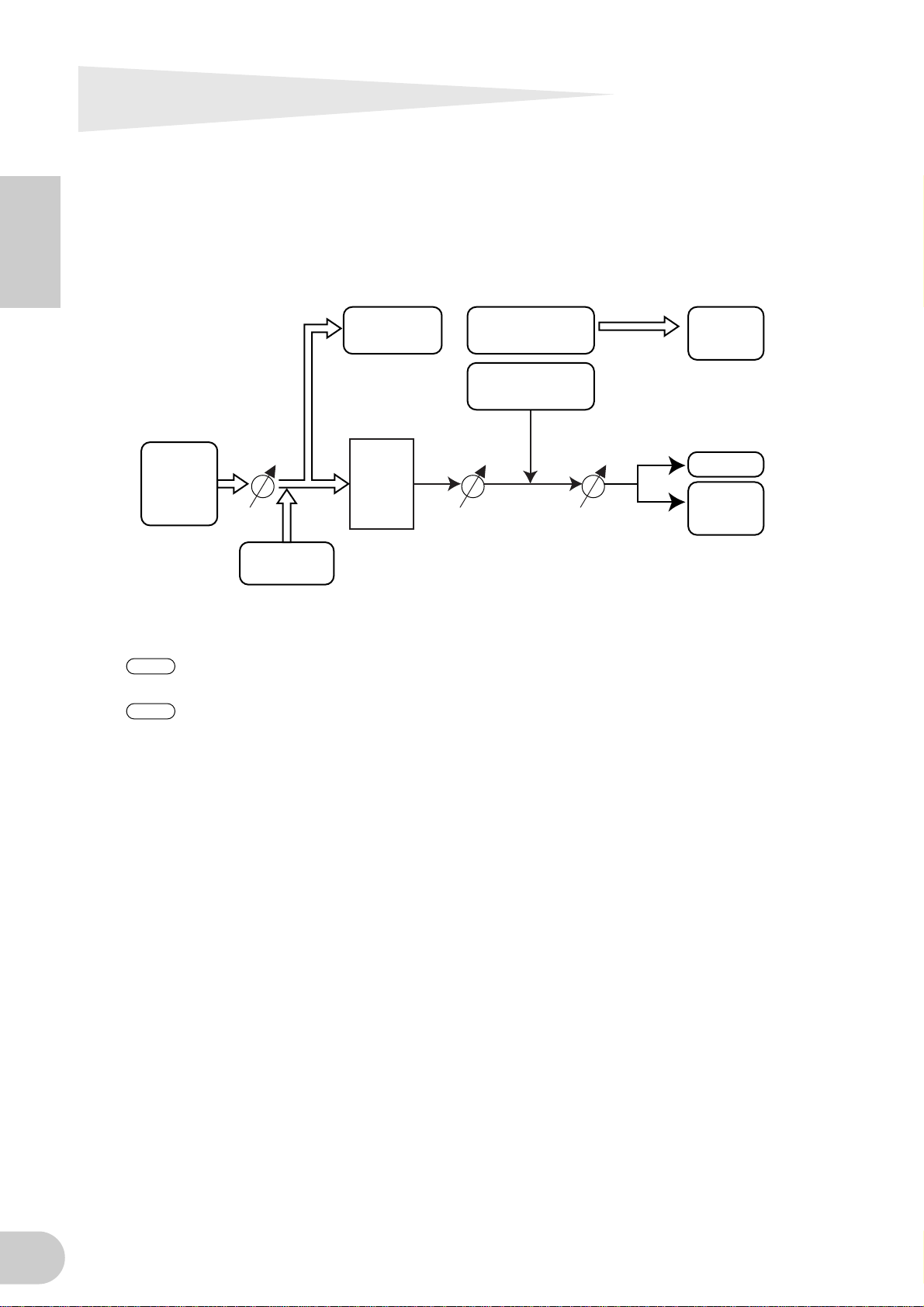
Direct Monitoring
Through the MASTER L & R jacks and the MASTER PHONES jack, you can directly monitor signals
input at INPUT 1-8 jacks or COAXIAL or OPTICAL DIGITAL STEREO INPUT jacks.
When an audio input signal, such as a guitar or vocal signal, is output through the computer,
latency (delay) may occur. However, this Direct Monitoring function enables you to monitor a signal before it is output to the connected computer, and thus avoids latency in the monitoring signal.
NOTE
If you wish to record to the DAW your vocal or musical instrument performance accompanying
the DAW’s background tracks, while listening to the sound through the i88X, turn off the monitoring function on the DAW. Otherwise, you will have to listen to a delayed sound (from the
DAW) and to a non-delayed sound (monitoring sound from the i88X) at the same time, resulting in a garbled sound.
mLAN INPUTS
1, 2
ANALOG
INPUTS
DIGITAL STEREO
INPUTS
1/2
3/4
5/6
7/8
MONITOR
SELECT
MONITOR
VOLUME
MASTER
VOLUME
PHONES
ANALOG
OUTPUTS
1/L, 2/R
1. Follow Steps 1 and 2 in “Connecting Musical Instruments and Microphones and Adjusting
the Input Level” on page 16 to connect the musical instruments and microphones to the
INPUT 1-8 jacks or COAXIAL or OPTICAL DIGITAL SETEREO INPUT jacks.
2. Press the [SELECT] button on the front panel (page 9) repeatedly to select a an input channel for direct monitoring through the MASTER OUT L & R jacks on the rear panel.
Press the switch briefly (less than one second) repeatedly to select monitoring channels in the
following sequence:
Off → CH1/2 → CH3/4 → CH5/6 → CH7/8 → DIGITAL STEREO -> Off
The MONITOR indicator (page 9) for the selected channels lights up red.
English
3. Adjust the [GAIN] controls for the INPUT channels (to which the musical instruments and
microphones are connected) and the [MASTER VOLUME] control.
4. Adjust the [MONITOR VOLUME] control.
Monitoring signals are output from the MASTER L & R jacks and the MASTER PHONES jack.
The [MONITOR VOLUME] control enables you to adjust the volume of the monitoring signals
without changing the recording level (input gain).
17
Page 18
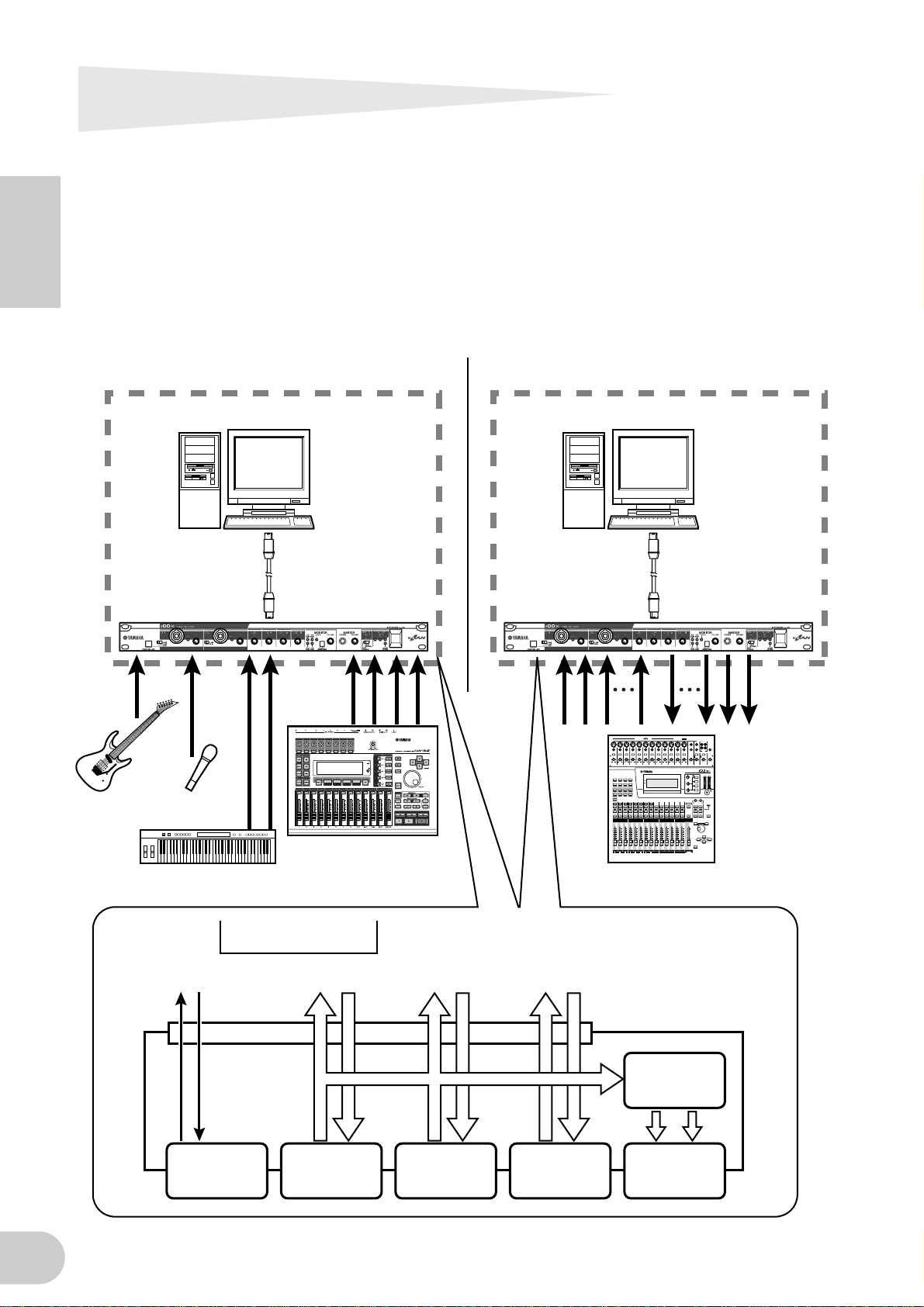
System Examples
1. Connecting the i88X to the computer
Connect the IEEE1394 connector on an IEEE1394-compatible computer to the mLAN connector
on the i88X using an IEEE1394 cable. In mLAN Auto Connector or mLAN Graphic Patchbay
(page 20), route the audio and MIDI signals between the computer and the i88X and set up the
wordclock.
This system enables you to transfer multiple audio streams from the connected musical instru-
English
ments and mixer to the computer simultaneously, and transfer multiple audio outputs from the
computer to the mixer simultaneously.
Guitar/
Bass
Connecting musical instruments
and a microphone Connecting a mixing console
IEEE1394-compatible computer IEEE1394-compatible computer
IEEE1394 cable
i88X i88X
Microphone
MTR
IEEE1394 cable
PAD
26dB
26dB226dB326dB426dB526dB626dB726dB826dB926dB1026dB1126dB
–60–16
–60–16
–60–16
+10 –34
+10 –34
+10 –34
GAIN
GAIN
GAIN
1
UTILITY MIDI SETUP VIEW
PAN/
DYNAMICS EQ/ATT Ø/DELAY
ROUTING
FADER MODE
EFFECT 1 EFFECT 2 OPTION I/O REMOTE
AUX 1
AUX 2 AUX 3 AUX 4
HOME
4
3
2
1
17
SEL
SEL
SEL
SEL
SOLO
SOLO
SOLO
SOLO
ON
ON
ON
ON
6
6
6
6
0
0
0
0
5
5
5
5
10
10
10
10
20
20
20
20
40
40
40
40
60
60
60
60
∞
∞
∞
∞
4
3
2
1
17
18 19 20 21 22 23 24
OFF
OFF
ON
ON
PHANTOM +48V
PHANTOM +48V
INPUT (BAL)
–60–16
–60–16
–60–16
+10 –34
+10 –34
+10 –34
+10 –34
GAIN
GAIN
GAIN
GAIN
FUNCTION
MEMORY
1 RETURN 2
8
7
6
5
232221201918
24
SEL
SEL
SEL
SEL
SOLO
SOLO
SOLO
SOLO
ON
ON
ON
ON
6
6
6
6
0
0
0
0
5
5
5
5
10
10
10
10
20
20
20
20
40
40
40
40
60
60
60
60
∞
∞
∞
∞
8
7
6
5
–10dBV (UNBAL)
131415
L
R
16
OUT
IN
2TR
PHONES
MONITOR
15/16
2TR IN
2TR IN
–60–16
–60–16
–60–16
–60–16
–60–16
–60–16 –20+10 100 100
–20+10
GAIN
+10 –34
9
SEL
SOLO
ON
6
0
5
10
20
40
60
∞
9
LEVEL LEVELGAIN
+10 –34
+10 –34
+10 –34
+10 –34
GAIN
GAIN
GAIN
GAIN
GAIN
MONITOR
12
OUT
13/14 15/16 PHONES
DIGITAL MIXING CONSOLE
L STEREO R
EQ
HIGH
CLIP
PAN
–3
–6
PAN
HI-MID
–9
–12
F
F
–15
–18
G
–24
LO-MID
–30
–36
–42
–48
G
LOW
SELECTED CHANNEL
STEREO
15/16
13/14
12
11
10
1 RETURN 2
MASTER
SELSEL
SEL
SEL
SEL
SEL
SEL
SEL
SOLO
SOLO SOLO
SOLO
SOLO
SOLO
SOLO
SOLO
ON
ON
ON
ON
ON
ON
ON ON
MEMORY
–1/DEC
+1/INC
PARAMETER
0
6
6
6
6
6
–5
0
0
0
0
0
–10
–15
5
5
5
5
5
–20
CURSOR
10
10
10
10
10
–30
–40
20
20
20
20
20
–50
40
40
40
40
40
–70
60
60
60
60
60
∞
∞
∞
∞
∞
– ∞
ENTER
STEREO
15/16
13/14
12
11
10
MASTER
Synthesizer
Computer
mLAN MIDI
IN/OUT
mLAN IN/OUT
1-8ch
mLAN IN/OUT
MIDI
IN/OUT
INPUT/
OUTPUT
1-8
18
mLAN IN/OUT
9-10ch
DIGITAL
STEREO
IN/OUT
mLAN
IN/OUT
ADAT
IN/OUT
Mixer
11-18ch
(44.1kHz/48kHz)
11-14ch
(88.2kHz/96kHz)
MONITOR
SELECT
MASTER OUT
L/R
Page 19
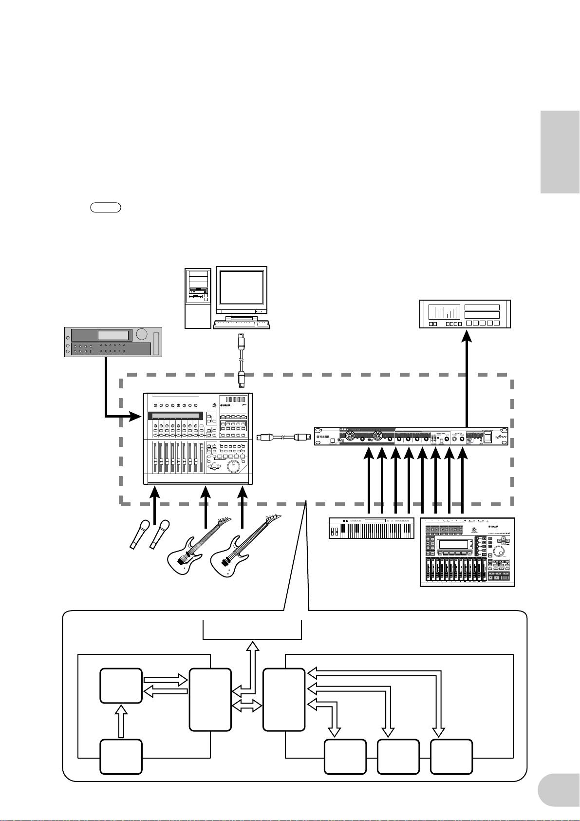
2. Using multiple mLAN devices
Connect the mLAN (IEEE1394) connector on the IEEE1394-compatible computer and the mLAN
(IEEE1394) connector on the 01X Digital Mixing Studio and on the i88X using IEEE1394 cables.
In mLAN Graphic Patchbay (refer to the mLAN Graphic Patchbay Online Manual), route the
audio and MIDI signals between the computer and the i88X and set up the wordclock.
This system enables you to make best use of the 01X Digital Mixing function (up to 28-channel
digital mixing). Using eight A/D inputs on the 01X and eight A/D inputs on the i88X enables you
to transfer 16-channel analog audio data to the 01X. Eight D/A outputs on the i88X are available, as well as MONITOR OUT (stereo) and STEREO/AUX OUT (stereo) on the 01X. These analog interface and the i88X COAXIAL and OPTICAL DIGITAL STEREO jacks expand analog and
digital input and output on the 01X.
English
NOTE
Sampler
The number of available input and output channels may vary depending on the specific mLAN
devices connected. For the best performance, it is recommended that you connect up to four
mLAN devices (including a computer) in a network. If the network contains an mLAN device
that is only compatible with a low transfer rate (200 Mbps (S200)), the number of devices and
channels available for connection will be reduced.
IEEE1394-compatible
computer
ADAT recorder
ADAT
IEEE1394 cable
01X
i88X
Microphones
Guitar
01X i88X
mLAN OUT
1-16ch
MIXER
mLAN IN
1-18ch
INPUT
1-8
mLAN
IN/OUT
Bass
Computer
mLAN
IN/OUT
Synthesizer
mLAN
IN/OUT
1-8ch
INPUT/
OUTPUT
1-8
mLAN
IN/OUT
9-10ch
DIGITAL
STEREO
IN/OUT
MTR
mLAN IN/OUT
11-18ch
(44.1kHz/48kHz)
11-14ch
(88.2kHz/96kHz)
ADAT
IN/OUT
19
Page 20
Making mLAN Connections
NOTE
In an mLAN system, you can easily configure and maintain the system, connect or disconnect the
mLAN connectors on the computer and each mLAN device (virtual audio /MIDI input and output
connectors), and make various mLAN connection settings (such as synchronization) by using the
mLAN Graphic Patchbay and mLAN Auto Connector software applications. There is no need to repatch audio and MIDI cables to accommodate various music production environments.
English
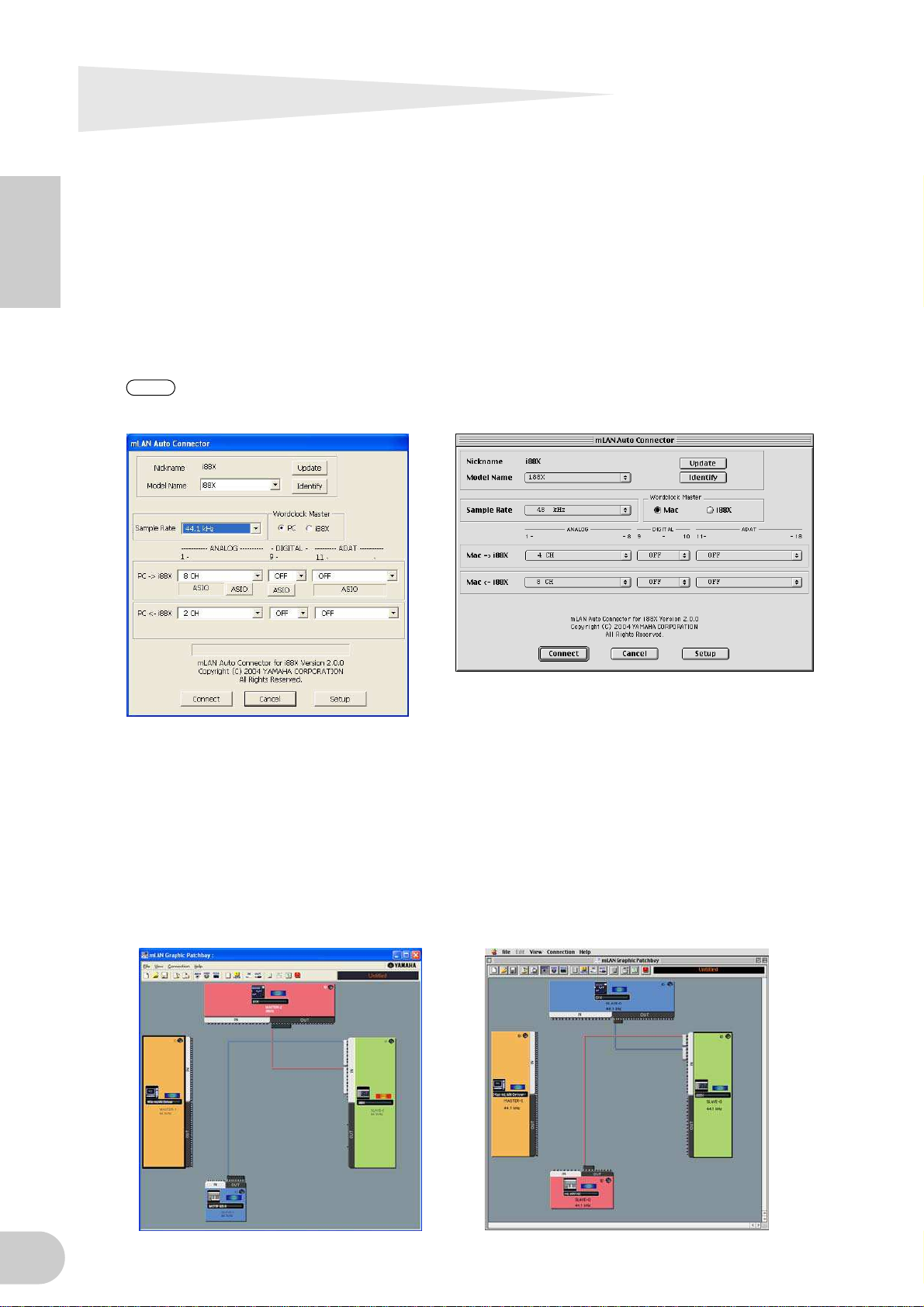
mLAN Auto Connector
This software application enables you to connect a computer to a single mLAN device.
It enables you to easily select wordclock and audio input and output channels.
For information on installing and using the software, refer to the separate Installation Guide.
You can also use mLAN Graphic Patchbay to connect a computer to a single mLAN device.
Windows Macintosh
mLAN Graphic Patchbay
This graphic software application enables you to manage mLAN connection settings for the connected computer and multiple mLAN devices. You can immediately grasp connections in their
entirety by viewing displayed mLAN system configuration graphics. You can also intuitively modify wordclock settings and audio and MIDI signal routing, much as if you were connecting physical cables.
For information on installing and using the software, refer to the separate Installation Guide and
the mLAN Graphic Patchbay Online Manual.
Windows Macintosh
20
Page 21
LED Indicators
Indicators Status Meaning
ACTIVE Steady blue The i88X is operating normally as an mLAN device.
Off An error has occurred during mLAN operation.
MASTER CLOCK INT Steady green The i88X is using the INTERNAL sampling frequency of
44.1 kHz.
ADAT Steady green The i88X is locking to the wordclock master (ADAT).
Flashing green The i88X is not locking to the wordclock master
(ADAT).
mLAN Steady green The i88X is locking to the wordclock master (ADAT).
Flashing green The i88X is not locking to the wordclock master
(ADAT).
English
MONITOR
/Sampling Rate
PEAK Steady red The analog input signal has reached the peak level.
NOTE
1/2 (44k) Steady red CH 1&2 are selected for monitoring output.
Flashing red The i88X is operating with a sampling frequency of
44.1 kHz.
3/4 (48k) Steady red CH 3&4 are selected for monitoring output.
Flashing red The i88X is operating with a sampling frequency of
48 kHz.
5/6 (88k) Steady red CH 5&6 are selected for monitoring output.
Flashing red The i88X is operating with a sampling frequency of
88 kHz.
7/8 (96k) Steady red CH 7&8 are selected for monitoring output.
Flashing red The i88X is operating with a sampling frequency of
96 kHz.
DIGITAL Steady red DIGITAL is selected for monitoring output.
When you press and hold down the [SELECT] switch for one second or longer, the MONITOR/Sampling Rate indicator for the current operating sampling frequency (44k, 48k, 88k, or
96k) flashes red.
21
Page 22

Troubleshooting
If you encounter a problem...
If you hear no sound or a strange sound, first check the items described below and take appropriate
action. If the problem persists, consult your Yamaha dealer.
■ No sound or very low volume level
• Are speakers or headphones connected correctly?
English
• Is your amp and other external devices turned on?
• Is the signal from the external device being input?
• Are all the level settings (of any tone generators, playback devices and the application itself) appropriate?
• The connection cable from the external device may be broken.
• Is the wordclock setting correct for both the i88X and the external device(s)?
............Refer to “Connecting a Computer to an mLAN device via mLAN” in the Installation
Guide, and “Wordclock Settings” in the mLAN Graphic Patchbay Online Manual.
• (For Windows) Is mLAN (mLAN Driver) set to “ON”? From the task bar, right click on the mLAN Manager
(mLAN icon).
• Are the other settings of mLAN appropriate? ........Refer to “Unable to communicate via mLAN (page 23).”
• If there are more than four devices (including a computer) on the network, the limit of the IEEE1394 BUS
bandwidth may be exceeded.
• The limit of the IEEE1394 BUS bandwidth may have been exceeded. Check the current bandwidth using
mLAN Graphic Patchbay, and disconnect some devices if necessary.
.......................................... Refer to “Menu Bar” in the mLAN Graphic Patchbay Online Manual.
• If there is an mLAN device that supports only S200 on the mLAN network, the IEEE1394 BUS bandwidth
may be reduced and its limit exceeded. Reduce the number of mLAN devices connected to the network, or
disconnect some devices as necessary.
.......................................... Refer to “Menu Bar” in the mLAN Graphic Patchbay Online Manual.
■ Distorted sound
• Is the [GAIN] control set correctly? ...................................................................................Refer to page 16.
• The connection cable from the external device may be broken.
• Is the wordclock setting correct for both the i88X and the external device(s)?
............Refer to “Connecting a Computer to an mLAN device via mLAN” in the Installation
Guide and “Wordclock Settings” in the mLAN Graphic Patchbay Online Manual.
• Make sure audio data was recorded at an appropriate level.
■ Noise is audible
• Is the latency setting of the mLAN Driver appropriate?
...........Refer to “mLAN Driver Setup” and “ASIO mLAN Control Panel” in the Installation Guide.
• (For Windows) Setting Hyper Threading to off in the BIOS settings may solve the problem.
• Is the wordclock setting correct for both the i88X and the external device(s)?
............Refer to “Connecting a Computer to an mLAN device via mLAN” in the Installation
Guide and “Wordclock Settings” in the mLAN Graphic Patchbay Online Manual.
• If the speed of your computer's hard disk is slow, problems may occur during recording and playback.
• If you connect/disconnect the LAN, USB or the cables to the mini jacks terminals on the Macintosh you are
using when using mLAN, some noise may be caused and/or data may be cut off. Make sure that you do
not insert or unplug any connections when using mLAN.
• Is the number of audio channels appropriate? The amount of audio channels that can be used simulta-
neously differs depending on the computer capacity and speed.
............Refer to “Connecting a Computer to an mLAN device via mLAN” in the Installation
Guide and “mLAN Connection Settings” in the mLAN Graphic Patchbay Online Manual.
• Is the sampling rate (wordclock) appropriate? A high sampling rate can be the cause of the noise depend-
ing on the computer capacity and speed.
............Refer to “Connecting a Computer to an mLAN device via mLAN” in the Installation
Guide and “mLAN Connection Settings” in the mLAN Graphic Patchbay Online Manual.
• Make sure that the appropriate number of devices is connected to the computer. Connection of too many
devices may cause noise, depending on the capacity of the computer.
• Are there any noise-producing devices (such as those containing power inverters, etc.) near the cables?
Move all cables away from any possible noise sources.
• Make sure the mLAN cable is not damaged. Cables that do not satisfy IEEE1394 standards may cause noise.
22
Page 23

• Do not run applications, such as anti-virus software, in the background. While using the mLAN system,
turn off all applications that run in background. If these applications remain on, driver operation may
become unstable and cause noise. If you do not plan to use the mLAN system, you can turn these applications on. (You can turn the mLAN driver on and off using mLAN Manager.)
■ Insufficient tracks for recording or playback
• Is the number of channels for mLAN audio receiving/sending (set on the mLAN Auto Connector and mLAN
Graphic Patchbay) appropriate?
............Refer to “Connecting a Computer to an mLAN device via mLAN” in the Installation
Guide and “mLAN Connection Settings” in the mLAN Graphic Patchbay Online Manual.
■ Unable to transfer MIDI data or Program Changes
• Are the MIDI cables connected correctly?
•A MIDI cable may be broken.
• Is the power turned on for the transmitting and receiving devices?
• Make sure the transmission and reception channels match.
■ Incorrect pitch
• Is the i88X operating on the same sampling frequency as the synchronized external device?
............Refer to “Connecting a Computer to an mLAN device via mLAN” in the Installation
Guide and “Wordclock Settings” in the mLAN Graphic Patchbay Online Manual.
• Is the master device operating in a stable way?
■ Unable to communicate via mLAN
• Has the driver been installed? ...................................................................... Refer to the Installation Guide.
• Is the mLAN cable properly connected? Check the connection; disconnect the mLAN cable once, then
insert it again.
• (For Windows) Is mLAN set to “ON”? From the task bar, right click on the mLAN Manager icon.
...................................................Refer to “Confirming the installation” in the Installation Guide.
• (For Windows) When adding a new IEEE 1394 card, right click on the mLAN Manager icon in the task bar
and select “ON.”.
...................................................Refer to “Confirming the installation” in the Installation Guide.
• Is the ACTIVE lamp on the rear panel of the i88X lit (in blue)? If it is not lit, check the followings:
- In mLAN Driver Setup, is the Status indicator blue? If not, restart the i88X and re-enable connection by
using mLAN Auto Connector or mLAN Graphic Patchbay.
............Refer to “Changing settings after installation” in the Installation Guide and the mLAN
Graphic Patchbay Online Manual.
• Has connection been enabled with mLAN Auto Connector and/or Graphic Patchbay? Re-enable connection if necessary.
............Refer to “Connecting a Computer to an mLAN device via mLAN” in the Installation
Guide and “mLAN Connection Settings” in the mLAN Graphic Patchbay Online Manual.
• Have you changed the device? Even if the model is the same, if the actual device is different, it is necessary
to re-enable connection by using Auto Connector and/or Graphic Patchbay.
............Refer to “Connecting a Computer to an mLAN device via mLAN” in the Installation
Guide and “mLAN Connection Settings” in the mLAN Graphic Patchbay Online Manual.
• Is there a loop connection? Check the cabling and make sure none of the devices are connected in a loop.
English
Computer
• There may be a limit on the IEEE 1394 interface of your computer as to the number of ports that can be
used simultaneously. Check how many ports can be used simultaneously.
•Turn off all devices on the mLAN network (except the computer) and re-connect each device one-by-one
until the device causing the problem is found.
• (For Windows) (When removing the mLAN bus from the [Safely Remove Hardware] setting of the task bar.)
Restart the computer when using mLAN again.
•With Macintosh notebook computers such as the iBook and PowerBook, always first connect the i88X and
mLAN cable then turn on the power of the i88X, before starting up the computer.
i88X
Computer
i88X
: IEEE 1394-equipped device
23
Page 24

■ An application, such as a DAW, fails to recognize the mLAN driver (MIDI/audio).
• (For Windows) Make sure mLAN has not been turned off. On the task bar, right-click mLAN Manager ( ),
then select ON. ... Refer to “Confirming the installation” in the Installation Guide and “mLAN Connection
Settings” in the mLAN Graphic Patchbay Online Manual.
• Make sure the i88X is connected to the mLAN cable and is powered on. Start mLAN Auto Connector or
mLAN Graphic Patchbay, then re-connect the device.
............Refer to “Confirming the installation” in the Installation Guide and “mLAN Connection
Settings” in the mLAN Graphic Patchbay Online Manual.
• (For Macintosh) To use an iBook or PowerBook in the system, connect the i88X to the Macintosh using an
mLAN cable, turn on the power to the i88X, then start the Macintosh.
English
• Make sure the mLAN settings are correct. ........ Refer to “Unable to communicate via mLAN” on page 23.”
■ The computer processing speed is too slow.
■ The computer’s CPU meter indicates a heavy processing load.
■ Playback response is delayed.
• Make sure your computer satisfies the system requirements.
........................................................... Refer to “System Requirements” in the Installation Guide.
• (For Windows) If you do not use the mLAN system, on the task bar right-click mLAN Manager ( ), then
select OFF (mLAN quits). ............................Refer to “Confirming the installation” in the Installation Guide.
•Try reducing the number of audio channels in mLAN Auto Connector or Graphic Patchbay.
............Refer to “Connecting the Computer and mLAN devices via mLAN” in the Installation
Guide and “mLAN Connection Settings” in the mLAN Graphic Patchbay Online Manual.
•Try increasing the latency value.
................................Refer to “Changing the Settings after Installation” in the Installation Guide.
• (For Macintosh) If a dual-CPU model awakes from Sleep or Suspend mode, processing speed may be
slowed. In this event, restart the computer.
• (For Windows) Refer to “Hints when using audio data (Windows).” ............ Refer to the Installation Guide.
• (For Windows) The condition may improve if you set “Hyper Threading” to “Disable.”
• Using mLAN Graphic Patchbay, try reducing the number of devices connected to the computer.
............Refer to “mLAN Connection Settings” in the mLAN Graphic Patchbay Online Manual.
• (For Macintosh) Turn off virtual memory.
• (For Macintosh) Disable Apple Talk.
24
■ Inconsistency in wordclock, or unable to exit from Auto Connector
• (For Windows) Mobile computers with Intel CPU
SpeedStep ™ technology is applied for some CPU’s (CPU for notebook PC). Please disable the SpeedStep
™ technology when mLAN is employed. SpeedStep™ technology changes CPU clock dynamically depending on the loading on the CPU to save the power consumption.
- How to disable the SpeedStep™ technology;
In almost all of the PC’s, BIOS has a function to select enabling or disabling the SpeedStep ™ technology. Please refer to the PC’s operating manual, or make inquiry to the PC manufacturer.
■ Unable to close the application or operating system
■ Unable to change the mLAN settings
■ Unable to uninstall mLAN Applications for Yamaha or mLAN Tools 2.0
• (For Windows) Is the mLAN (WDM) driver selected as the default audio device for the system?
- Select [Start | Control Panel | Sounds and Audio Devices | Voice].
Make sure that something other than “mLAN Audio 01” is selected for the [Voice playback] and [Voice
recording] settings.
- Select [Start | Control Panel | Sounds and Audio Devices | Audio].
Make sure that something other than “mLAN Audio 01” is selected for the [Sound playback] and [Sound
recording] settings.
- In “MIDI music playback,” select any option other than the range of options from “mLAN
MIDI Out” through “mLAN MIDI Out (8).”
• (For Windows) Select [Start | Control Panel | Sounds and Audio Devices | Sounds]. And select “No sounds”
in the [Sound scheme], then execute again.
• (For Windows) If you cannot quit mLAN (by selecting “OFF” after right clicking the mLAN icon in the task
bar), end the processes listed below manually. ([Ctrl] + [Alt] + [Delete] → [Processes] → select process →
[End process]) When finished, start mLAN Manager to change the mLAN settings again.
- mLANVDevice.exe
- mLANTFamily.exe
- mLANSoftPH.exe
- mLANManager.exe
Page 25

To change mLAN settings, select [Start | (All) Programs | Start Up], then start mLAN Manager.
- (When a message such as “file cannot be found” appears when uninstalling:)
Try executing the installation once more, then uninstall again.
■ (Windows) mLAN Manager (the mLAN icon in the task bar) has disappeared.
• Select [Start | (All) Programs | Start Up (or mLAN Tools)], then select mLAN Manager.
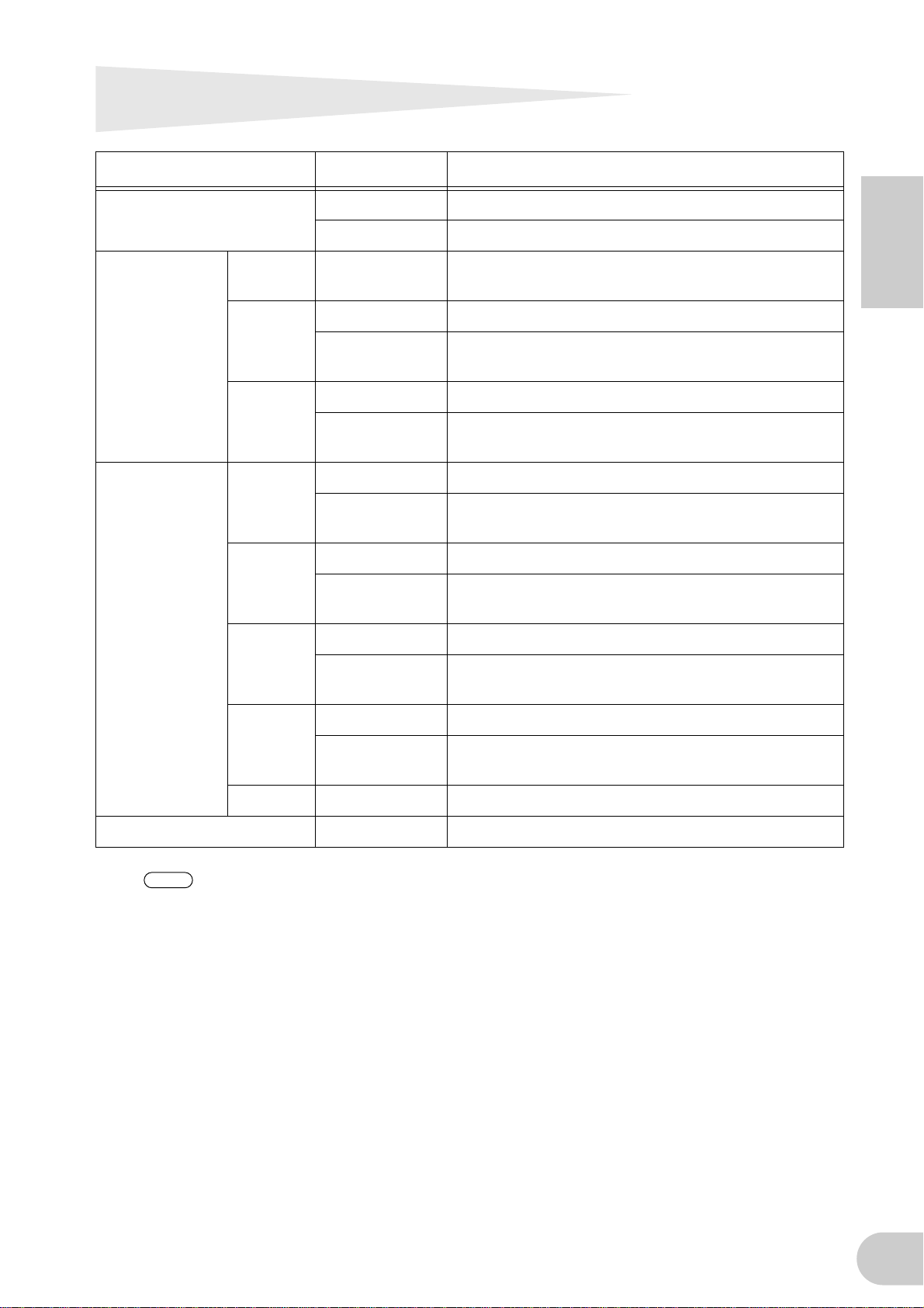
Specifications
■ General Specifications
Sampling Frequency Internal, External
Frequency
Response
Total Harmonic Distortion Less than 0.01%
Dynamic Range 110dB Line Input to Master Output L/R (1/2ch) or 3–8 ch
Noise level –100dBu (Output Vol: Min.), –90dBu (Output Vol: Max.)
Crosstalk 75dB 1kHz
AD converter
DA converter
Fs 44.1kHz, 48kHz 20Hz to 20kHz 0+1/–3dB, Input to Master Output L/R (Fs 48kHz, MIC/LINE)
Fs 88.2kHz, 96kHz 20Hz to 40kHz 0+1/–3dB, Input to Master Output L/R (Fs 96kHz, MIC/LINE)
24bit Linear, 128times over sampling (Fs 44.1,48kHz) / 64time over sampling
(Fs 88.2,96kHz)
24bit Linear, 128times over sampling (Fs 44.1,48kHz) / 64time over sampling
(Fs 88.2,96kHz)
Normal Rate Fs 44.1kHz(–10%) to 48kHz(+6%)
Double Rate Fs 88.2kHz(–10%) to 96kHz(+6%)
1kHz, Line Input to Master Output L/R (Input Gain = Min,
Output Vol = Max)
English
*1
Interface Functions
Compatible mLAN transfer rate S400 (400Mbps) / S200 (200Mbps)
18ch Input / 18ch Output (Fs 44.1kHz, 48kHz)
mLAN Audio I/F
MIDI I/F 1 Input port / 1 Output port
Type: Input (Analog) 8ch, Digital Input 2ch, ADAT Input 8ch
14ch Input / 14ch Output (Fs 88.2kHz, 96kHz)
Type: Input (Analog) 8ch, Digital Input 2ch, ADAT Input 4ch
■ Input/Output Specifications
Analog Input Connector
INPUT 1,2
INPUT 3-8
INSERT IN 1-2
Analog Output Connector
OUTPUT 1-8
(MASTER OUT L/R)
INSERT OUT 1-2
PHONES TRS Phone, UnBalanced — 100mW+100mW 33Ω (33Ω)
XLR/TRS Phone Combo
Balanced, +48V ±3V Phantom,
Mic/Line/Hi-Z
TRS Phone
TRS Phone*4, UnBalanced
*3
, Balanced, Line
TRS Phone, Balanced
*4
TRS Phone
, UnBalanced
*2
,
*3
–60dBu to –16dBu (Mic) –2dBu
–34dBu to +10dBu (Line) +24dBu
–56dBu to –12dBu (Hi-Z) +2dBu 500kΩ
Nominal Max. before clip Input Impedance
–20dBu to +10dBu +24dBu 10kΩ
–2dBu +12dBu 10kΩ
Nominal Max. before clip
+4dBu +18dBu 2kΩ (10kΩ)
–2dBu +12dBu 600Ω (10kΩ)
Input level
3kΩ
Output level
Actual Load Impedance
(Rated Load Impedance)
25
Page 26

Digital Input/
Output
ADAT/DIGITAL
OPTICAL IN, OUT
DIGITAL STEREO
IN, OUT
MIDI IN, OUT A/B DIN 5pin MIDI —
English
mLAN 1/2 IEEE1394 6pin mLAN — Compatible with S400 and S200
*1: Signal input from ADAT-compatible device: Normal Rate Fs 44.1KHz(–6%) to 48KHz(+6%)
*2: Always balanced, regardless of whether a XLR-3-31 or TRS phone is used. (1=GND, 2=HOT, 3=COLD/Tip=HOT, Ring=COLD,
Sleeve=GND)
*3: Balanced Phone (Tip=HOT, Ring=COLD, Sleeve=GND)
*4: INSERT IN & OUT feature unbalanced phone jacks. (Tip = OUTPUT, Ring=INPUT, Sleeve=GND)
*5: ALESIS proprietary multi-channel optical digital interface format
In these specifications, when dBu represents a specific voltage, 0 dBu is referenced to 0.775 Vrms.
Connector Format
*5
ADAT
OPTICAL
RCA PIN IEC-60958 Consumer use 0.5Vpp/75Ω
IEC-60958 Consumer use
(DIGITAL)
Double Rate Fs 88.2KHz(–6%) to 96KHz(+6%)
Recommended
output level
—
—
Other details
Supports DOUBLE
(up to 96 kHz).
The IN jack features an internal
sampling rate converter.
■ Control
Input Gain Gain Knob 1, 2, 3, 4, 5/6, 7/8
Phantom Switch
Gain Select Switch (PAD Switch) Input Ch 1 : Mic/Line/Hi-Z, Input Ch 2 : Mic/Line
Peak LED Input 1, 2 channel
Monitor Select Switch (Fs Indicator)
Monitor LED (Fs Indicator)
Monitor Volume Direct Monitoring Volume for selected channel by monitor switch
Master Volume Output Level of Master Output L/R and Phones
Optical Select Switch Digital / ADAT Normal / ADAT Double
Master Clock LED mLAN / ADAT / Internal (fixed at 44.1kHz)
mLAN Active LED For Information of mLAN’s situation
Power Switch Stand by/On switch
*6: Phantom power (+48 V) is not supplied when the TRS phone is used. If the [HI-Z/LINE/MIC] switch is set to HI-Z, phantom
power is not supplied to INPUT jack 1.
Phantom (+48V) On/Off for Input1,2 channel with LED
Direct Monitoring Channel Selector : 1/2, 3/4, 5/6, 7/8, Digital In / Fs Indicator
(holding down a while)
Direct Monitoring Channel Selector : 1/2, 3/4, 5/6, 7/8, Digital In / Fs Indicator :
44.1, 48, 88.2, 96kHz
*6
■ Others
Supplied Accessories
Power Consumption 16W
Dimensions 480(W) x 372.7(D) x 44(H)
Weight 3.9kg
Power Adaptor (PA-5D), Owner’s Manual set, CD-ROM x 2, mLAN (IEEE1394)
cable
* Specifications and descriptions in this owner’s manual are for information purposes only. Yamaha
Corp. reserves the right to change or modify products or specifications at any time without prior
notice. Since specifications, equipmentr or options may not be the same in every locale, please
check with your Yamaha dealer.
26
Page 27

VORSICHTSMASSNAHMEN
Gefahr durch Wasser
Brandschutz
Falls Sie etwas ungewöhnliches am Gerät bemerken
BITTE SORGFÄLTIG DURCHLESEN, EHE SIE WEITERMACHEN
* Heben Sie diese Anleitung sorgfältig auf, damit Sie später einmal nachschlagen können.
WARNUNG
Befolgen Sie unbedingt die nachfolgend beschriebenen grundlegenden Vorsichtsmaßnahmen, um die Gefahr einer
schwer wiegenden Verletzung oder sogar tödlicher Unfälle, von elektrischen Schlägen, Kurzschlüssen,
Beschädigungen, Feuer oder sonstigen Gefahren zu vermeiden. Zu diesen Vorsichtsmaßnahmen gehören die
folgenden Punkte, die jedoch keine abschließende Aufzählung darstellen:
Stromversorgung/Netzadapter
• Verwenden Sie ausschließlich die für das Instrument vorgeschriebene richtige
Netzspannung. Die erforderliche Spannung finden Sie auf dem Typenschild
des Instruments.
• Ausschließlich den vorgeschriebenen Adapter (PA-5D oder einen
gleichwertigen, von Yamaha empfohlenen) verwenden. Wenn Sie den falschen
Adapter einsetzen, kann dies zu Schäden am Instrument oder zu Überhitzung
führen.
• Prüfen Sie den Netzstecker in regelmäßigen Abständen und entfernen Sie
eventuell vorhandenen Staub oder Schmutz, der sich angesammelt haben
kann.
• Verlegen Sie das Netzkabel niemals in der Nähe von Wärmequellen, etwa
Heizkörpern oder Heizstrahlern, biegen Sie es nicht übermäßig und
beschädigen Sie es nicht auf sonstige Weise, stellen Sie keine schweren
Gegenstände darauf und verlegen Sie es nicht an einer Stelle, wo jemand
darauftreten, darüber stolpern oder etwas darüber rollen könnte.
Öffnen verboten!
• Verlegen Sie das Kabel des Adapters niemals in der Nähe von Wärmequellen,
etwa Heizkörpern oder Heizstrahlern, biegen Sie es nicht übermäßig und
beschädigen Sie es nicht auf sonstige Weise, stellen Sie keine schweren
Gegenstände darauf und verlegen Sie es nicht an einer Stelle, wo jemand
darauftreten, darüber stolpern oder etwas darüber rollen könnte.
• Achten Sie darauf, dass das Instrument nicht durch Regen nass wird,
verwenden Sie es nicht in der Nähe von Wasser oder unter feuchten oder
nassen Umgebungsbedingungen und stellen Sie auch keine Behälter mit
Flüssigkeiten darauf, die herausschwappen und in Öffnungen hineinfließen
könnte.
• Schließen Sie den Netzstecker niemals mit nassen Händen an oder ziehen Sie
ihn heraus.
• Stellen Sie keine offenen Flammen, wie z.B. Kerzen, auf dem Gerät ab. Eine
offene Flamme könnte umstürzen und einen Brand verursachen.
• Wenn das Kabel des Adapters ausgefranst oder beschädigt ist, wenn es
während der Verwendung des Instruments zu einem plötzlichen Tonausfall
kommt, oder wenn es einen ungewöhnlichen Geruch oder Rauch erzeugen
sollte, schalten Sie sofort den Einschalter aus, ziehen Sie den Adapterstecker
aus der Netzsteckdose und lassen Sie das Instrument von einem qualifizierten
Yamaha-Kundendienstfachmann prüfen.
Deutsch
VORSICHT
Befolgen Sie unbedingt die nachfolgend beschriebenen grundlegenden Vorsichtsmaßnahmen, um die Gefahr von
Verletzungen bei Ihnen oder Dritten, sowie Beschädigungen des Instruments oder anderer Gegenstände zu
vermeiden. Zu diesen Vorsichtsmaßnahmen gehören die folgenden Punkte, die jedoch keine abschließende
Aufzählung darstellen:
Nähe einer Heizung oder Lagerung tagsüber in einem geschlossenen
Stromversorgung/Netzadapter
• Wenn Sie den Netzstecker aus dem Instrument oder der Netzsteckdose
abziehen, ziehen Sie stets am Stecker selbst und niemals am Kabel. Wenn Sie
am Kabel ziehen, kann dieses beschädigt werden.
• Ziehen Sie während eines Gewitters oder wenn Sie das Instrument längere Zeit
nicht benutzen den Netzadapter aus der Netzsteckdose.
• Schließen Sie das Instrument niemals mit einem Mehrfachsteckverbinder an
eine Steckdose an. Hierdurch kann sich die Tonqualität verschlechtern oder
sich die Netzsteckdose überhitzen.
Aufstellort
• Setzen Sie das Instrument niemals übermäßigem Staub, Vibrationen oder
extremer Kälte oder Hitze aus (etwa durch direkte Sonneneinstrahlung, die
(3)-7 1/2
Fahrzeug), um die Möglichkeit auszuschalten, dass sich das Bedienfeld
verzieht oder Bauteile im Innern beschädigt werden.
• Betreiben Sie das Instrument nicht in der Nähe von Fernsehgeräten, Radios,
Stereoanlagen, Mobiltelefonen oder anderen elektrischen Geräten.
Anderenfalls kann durch das Instrument oder die anderen Geräte ein
Rauschen entstehen.
• Stellen Sie das Instrument nicht an einer instabilen Position ab, wo es
versehentlich umstürzen könnte.
• Ehe Sie das Instrument bewegen, trennen Sie alle angeschlossenen Adapter
oder sonstigen Kabelverbindungen ab.
• Verwenden Sie nur das Regal, der bzw. das für dieses Instrument
vorgeschrieben ist. Beim Anbringen des Ständers oder des Regals
ausschließlich die mitgelieferten Schrauben verwenden. Andernfalls kann es
zu Beschädigung von Bauteilen im Innern kommen oder das Instrument
umfallen.
3
Page 28

Anschlüsse
Vorsicht bei der Handhabung
• Ehe Sie das Instrument an andere elektronische Komponenten anschließen,
schalten Sie die Stromversorgung aller Geräte aus. Ehe Sie die
Stromversorgung für alle Komponenten an- oder ausschalten, stellen Sie bitte
alle Lautstärkepegel auf die kleinste Lautstärke ein. Auch immer sicherstellen,
dass die Lautstärke aller Komponenten auf den kleinsten Pegel gestellt werden
und die Lautstärke dann langsam gesteigert wird, während das Instrument
gespielt wird, um den gewünschten Hörpegel einzustellen.
Wartung
• Verwenden Sie zur Reinigung des Instruments ein weiches, trockenes Tuch.
Verwenden Sie keinesfalls Farbverdünner, Lösungsmittel,
Reinigungsflüssigkeiten oder chemisch inprägnierte Wischtücher.
Yamaha ist nicht für solche Schäden verantwortlich, die durch falsche Verwendung des Instruments oder durch Veränderungen am Instrument hervorgerufen
wurden, oder wenn Daten verloren gehen oder zerstört werden
.
• Stecken Sie nicht einen Finger oder die Hand in Öffnungen des Instruments.
• tecken Sie niemals Papier, metallene oder sonstige Gegenstände in die
Öffnungen des Bedienfeldes. Lassen Sie derartige Gegenstände auch nicht in
diese Öffnungen fallen. Falls dies doch geschieht, schalten Sie sofort die
Stromversorgung aus und ziehen Sie das Netzkabel aus der Steckdose. Lassen
Sie das Instrument anschließend von einem autorisierten Yamaha-Kundendienst
überprüfen.
• Legen Sie ferner keine Vinyl-, Kunststoff- oder Gummigegenstände auf das
Instrument, da sich hierdurch das Bedienfeld oder die Tastatur verfärben
könnten.
• Lehnen oder setzen Sie sich nicht auf das Instrument, legen Sie keine
schweren Gegenstände darauf und üben Sie nicht mehr Kraft auf Tasten,
Schalter oder Steckerverbinder aus als unbedingt erforderlich.
• Spielen Sie das Instrument nicht länge Zeit mit hoher oder unangenehmer
Lautstärke, da es hierdurch zu permanentem Gehörverlust kommen kann.
Falls Sie Gehörverlust bemerken oder ein Klingeln im Ohr feststellen, lassen
Sie sich von Ihrem Arzt beraten.
Deutsch
Stellen Sie stets die Stromversorgung aus, wenn das Instrument nicht verwendet wird.
Auch wenn sich der Netzschalter in der „STANDBY“-Position, weist das Instrument noch einen minimalen Stromverbrauch auf. Falls Sie das Instrument für längere Zeit
nicht nutzen möchten, sollten Sie unbedingt den Netzadapter aus der Steckdose ziehen.
(3)-7 2/2
Entfernen der Gummistopper zur Installation in einem Stereoregal
Das i88X hat vier abnehmbare Gummistopper. Falls das i88X nicht in Ihren Stereoschrank passt, weil
die Stopper gegen ein anderes Gerät stoßen, entfernen Sie die Stopper wie nachstehend beschrieben.
Legen Sie sich, bevor Sie die Stopper entfernen, ein dünnes, spitzes Werkzeug zurecht – wie z.B. eine
Sicherheitsnadel oder eine gerade gebogene Büroklammer.
VORSICHT
Verwenden Sie kein Werkzeug, das leicht brechen oder verbogen werden könnte, wie z.B. einen Zahnstocher
oder einen dünnen Draht.
1. Drehen Sie das i88X um, so dass die Unterseite nach oben zeigt.
2. Schieben Sie das Werkzeug zwischen den
Gummistopper und den Plastikniet (wie
abgebildet).
3. Ziehen Sie den Niet nach oben und aus
dem Gerät heraus.
4
Niet
Spitzes
Werkzeug
4. Ziehen Sie die Gummistopper heraus.
Gummistopper
Um die entfernten Gummistopper wieder anzubringen, gehen Sie in umgekehrter Reihenfolge
vor; setzen Sie dabei die Niete senkrecht ein.
Page 29

Einführung
Vielen Dank für den Kauf des Audio/MIDI Interface i88X von Yamaha.
Durch Anschluss des i88X an einen Computer können Sie Ihre Musikproduktionsumgebung erweitern,
wenn Sie einen Audiosequenzer auf dem Computer benutzen.
Das i88X unterstützt mLAN, ein digitales Netzwerk für Musikdaten auf Basis der
Hochleistungsschnittstelle IEEE 1394 für die serielle Datenübertragung. Mit dem i88X können Sie sehr
einfach anspruchsvolle Netzwerke für Audio- und MIDI-Signale mit IEEE 1394 aufbauen, ohne
Kabelverbindungen immer neu herstellen zu müssen, wie es bei konventionellen Systemen der Fall war.
Um alle Vorteile der Funktionen des i88X nutzen zu können, lesen Sie diese Anleitung bitte genau
durch. Bewahren Sie die Anleitung zum späteren Nachschlagen bitte gut auf.
Lieferumfang
i88X-Gerät
•
•
Tools for i88X/mLAN16E (CD-ROM)
•
Plug-in-Effekte (CD-ROM)
•
mLAN-Kabel (IEEE-1394-Kabel) (6-Pol auf 6-Pol)
•
Netzadapter: PA-5D
•
Bedienungsanleitung (dieses Handbuch)
•
Installationshandbuch für Tools for i88X/mLAN16E
•
Anwenderkarte (enthält die Seriennummer für die mitgelieferte Effekt-Plug-in-Software)
Informationen zur beiliegenden CD-ROM
Die dem i88X beiliegende CD-ROM enthält Software, die für die Verwendung des i88X nützlich sein
kann. Diese Software enthält Treiber, die zum Anschluss des i88X an einen Computer benötigt
werden. Sie enthält auch Software, mit der Sie Audio- und MIDI-Signale zwischen mLAN-Geräten
und Plug-in-Effekten routen können. Weitere Informationen finden Sie im Installationshandbuch für
die „Tools for i88X/mLAN16E“ und in den entsprechenden Online-Anleitungen.
Yamaha kann weder für Schäden verantwortlich gemacht werden, die durch
Fehlbedienung oder durch Veränderungen am Gerät hervorgerufen wurden, noch für
Datenverluste oder Zerstörung von Daten.
Deutsch
•
Die Abbildungen und LCD-Anzeigen in dieser Bedienungsanleitung dienen lediglich der Illustration
und können vom tatsächlichen Erscheinungsbild auf Ihrem Gerät abweichen.
•
MIDI ist eine eingetragene Marke der Association of Musical Electronics Industry (AMEI).
•
mLAN ist ein Warenzeichen der Yamaha Corporation.
•
Die Firmen- und Produktnamen in dieser Bedienungsanleitung sind Marken bzw. eingetragene
Marken der jeweiligen Firmen.
5
Page 30

Leistungsmerkmale
■ Schnelle Datenübertragung über mLAN
Wenn Sie das i88X über IEEE-1394- (FireWire/i.LINK)-Kabel mit einem Computer und anderen mLANGeräten verbinden, können Sie Audiodaten und MIDI-Signale auf mehreren Kanälen zu und von einer
computergestützten DAW (Digital Audio Workstation) und anderen mLAN-Geräten übertragen (mit
400 Mbps [S400]).
■ Bis zu 18 Audio-I/O-Kanäle
•
Das i88X besitzt zwei MIC/LINE-Eingänge und sechs LINE-Eingänge. Die Eingänge 1 und 2 besitzen
vom DM2000 übernommene klangtransparente Mikrofon-Vorverstärker und Phantomspeisung und
können sowohl mit XLR- als auch mit TRS-Klinkensteckern belegt werden. Die Eingänge 3–8 können
mit TRS-Klinkensteckern belegt werden (Seiten 8 und 11).
•
Eingang 1 besitzt zusätzlich einen HI-Z-Eingang (mit hoher Impedanz) für den Anschluss
hochohmiger Musikinstrumente wie Gitarre oder Bass (Seite 8).
•
An den Insert-I/O-Buchsen können Sie ein externes Effektgerät anschließen (Seite 11).
•
Das i88X bietet außerdem einen Sampling-Rate-Konverter, der Sampling-Frequenzen von 44,1 kHz
bis 96 kHz unterstützt.
Deutsch
•
Über die MIDI-Ein- und Ausgänge können Sie externe MIDI-Geräte in das mLAN-System einbinden
(Seite 11).
•
Das i88X kann bis zu 18 Ein- und Ausgangskanäle gleichzeitig verarbeiten, wenn es mit den
Sampling-Frequenzen 48 kHz oder 44,1 kHz betrieben wird, und bis zu 14 Ein- und Ausgangskanäle
bei Betrieb mit 96 kHz oder 88,2 kHz.
■ Audio-Eigenschaften
•
Kompatible Sampling-Frequenzen: 44.1 kHz, 48 kHz, 88,2 kHz, 96 kHz
•
Lineare A/D- und D/A-Konverter mit 24 Bit und 128-fachem Oversampling (bei einer SamplingFrequenz von 48 kHz oder 44,1 kHz) oder 64-fachem Oversampling (bei einer Sampling-Frequenz
von 96 kHz oder 88,2 kHz)
•
Frequenzgang: 20 Hz – 20 kHz, Standard-Dynamikumfang: 110 dB
■ Direct-Monitoring-Funktion (direktes Abhören)
•
Hiermit können Sie das in der DAW aufgezeichnete Signal ohne Verzögerung (Latenz) hören
(Seite 17).
■ Integriertes Paket mit Plug-in-Effekten
•
Vier VST/AU-Plug-in-Effekte, einschließlich Equalizer, Gesangs- und Mastering-Effekten usw.
Inhaltsverzeichnis
Entfernen der Gummistopper zur Installation in einem Stereoregal .................................. 4
Einführung............................................................................................................................. 5
Lieferumfang......................................................................................................................... 5
Leistungsmerkmale ...............................................................................................................6
Grundlagen zu mLAN ........................................................................................................... 7
Funktionsdiagramm für Tonsignalausgabe .......................................................................... 7
Bezeichnungen und Funktionen........................................................................................... 8
Vorderes Bedienfeld ...................................................................................................... 8
Rückseite..................................................................................................................... 11
Ein- und Ausschalten des i88X und der angeschlossenen Geräte ..................................... 12
Anschließen externer Geräte.............................................................................................. 13
Anschluss von Musikinstrumenten und Mikrofonen; Einstellen des Eingangspegels ....... 16
Direktes Abhören ................................................................................................................17
Systembeispiele................................................................................................................... 18
Herstellen von mLAN-Verbindungen.................................................................................. 20
LED-Anzeigen ...................................................................................................................... 21
Fehlerbehebung ..................................................................................................................22
Technische Daten................................................................................................................25
6
Page 31

Grundlagen zu mLAN
mLAN ist ein digitales Netzwerk für Musik, die auf der Basis von IEEE 1394 aufgebaut wurde, einem
Industriestandard-Protokoll für Hochgeschwindigkeits-Datenübertragung.
Digital-Music-Umgebungen ohne mLAN erfordern Dutzende von Kabeln für verschiedene Geräte und
Zwecke, einschließlich MIDI-Kabeln und Audio-Kabeln für das Routing von MIDI- und Audiosignalen.
Wenn Sie in solchen Systemen etwas ändern möchten, müssen Sie diese Kabel physikalisch herausziehen
und anders anschließen.
Wenn Sie Ihrem System zum Beispiel einen weiteren Synthesizer hinzufügen möchten, benötigen Sie
zwei MIDI-Kabel und zwei weitere Kabel für Audiosignale (für Stereo). Die Herstellung der geeigneten
Verbindung kann ein spezielles Wissen über Eingänge, Ausgänge, Stereoeinstellungen und eventuell
auch über Lastimpedanzen erfordern.
Je größer das System, desto komplizierter und teurer werden die Verbindungen, und die Fehlerhäufigkeit
und allgemeine Schwierigkeiten nehmen zu. Es braucht oft genug viel Zeit und Mühe, solche Fehler und
deren Ursache zu finden und zu beseitigen. Sie haben vielleicht schon einmal erlebt, wie es einem beim
Verfolgen von Signalwegen im Kabelsalat ergehen kann.
mLAN vereinfacht die Kabelverbindungen, indem nur ein einziger Kabeltyp (IEEE 1394) verwendet wird,
wodurch Sie mit nur wenigen Verbindungen extrem ausgeklügelte Systeme konfigurieren können. Um
Signalwege von MIDI- und Audiosignalen zwischen mLAN-Geräten zu ändern, müssen Sie keine
Kabelverbindungen ändern.
Deutsch
Funktionsdiagramm für Tonsignalausgabe
1. Installieren Sie die Tools für i88X/mLAN16E.
........... Siehe „Installieren der Software“ in der Installationsanleitung.
2. Verbinden Sie den Computer und die mLAN-Geräte mithilfe der IEEE-1394-Kabel.
........... Siehe Seite 13.
3. Schalten Sie mLAN Manager ein (nur Windows).
........... Siehe „Bestätigen der Installation“ in der Installationsanleitung.
4. Um einen Computer direkt mit einem einzigen mLAN-Gerät zu verbinden, starten Sie zuerst
den mLAN Auto Connector (Assistent zum autom. Herstellen von mLAN-Verbindungen). Um
einen Computer mit mehreren mLAN-Geräten zu verbinden, starten Sie die mLAN Graphic
Patchbay (Grafische mLAN-Verbindungsmatrix).
........... Siehe Seite 20
5. Konfigurieren Sie die Verbindungen im mLAN Auto Connector oder in der mLAN Graphic
Patchbay.
........... Bei Verwendung von Auto Connector: Siehe „Anschließen des Computers und der
mLAN-Geräte über mLAN“ in der Installationsanleitung.
........... Bei Verwendung der Graphic Patchbay: Siehe „mLAN-Verbindungseinstellungen“
in der Online-Anleitung zur Graphic Patchbay.
6. Geben Sie anhand der Bedienungsanleitung Ihrer DAW (Digital Audio Workstation), Ihres
Audiosequenzers und/oder der angeschlossenen Geräte die Audio- und MIDI-Ein- und Ausgänge an.
Für die folgenden Schritte schlagen Sie bitte im Benutzerhandbuch der verwendeten Software und der
angeschlossenen Geräte nach.
HINWEIS
In diesem Handbuch wird das Einrichten von Audio-, MIDI- und Wordclock-Signalwegen als das
Herstellen von „mLAN-Verbindungen“ bezeichnet.
7
Page 32

Bezeichnungen und Funktionen
Vorderes Bedienfeld
1 Schalter [PHANTOM +48V]
Deutsch
2
8
HINWEIS
Die links von den Namen angegebenen Zahlen (1-5, 7-A, E-K, und M) entsprechen den
im Blockdiagramm angegebenen Zahlen auf des Rückseiten.
1 2 3 4 3 4 5 76 8 9 0 A CB D5
Dieser Schalter liefert eine Phantomspannung von
+48 V an die XLR-Buchsen der Eingänge INPUT Nr.
1 und 2 (3). Bedenken Sie, dass
Phantomspeisung nicht geliefert wird, wenn Sie
ein externes Gerät an einer der TRS-Klinkenbuchsen an der Geräterückseite angeschlossen
haben. Schalten Sie diesen Schalter ein, wenn Sie
an den INPUT-Buchsen 1 oder 2 (3) ein Kondensator-mikrofon anschließen, das eine externe
+48 V-Versorgung benötigt. Wenn der Schalter
eingeschaltet ist, leuchtet dessen Anzeige auf.
•
Schalten Sie diesen Schalter in jedem
Fall aus, wenn Sie an den XLRBuchsen INPUT 1 oder 2 ein Gerät
anschließen, das keine externe
Spannungsversorgung benötigt.
Anderenfalls wird Phantomspannung
an dieses Gerät geliefert, was
vermutlich zu Schäden an diesem
Gerät führen kann.
• Wenn Sie ein Gerät anschließen, das
externe Spannungsversorgung
erfordert, schließen Sie das Gerät
zunächst am XLR-Anschluss an und
schalten dann die Phantomspeisung
ein.
• Wenn Phantomspeisung eingeschaltet
ist, werden immer beide INPUTBuchsen (1 und 2) versorgt.
• Phantomspeisung wird nicht an TRSKlinkenbuchsen geliefert.
HINWEIS
[(HI-Z)/LINE/MIC]-Schalter
Mit diesem Schalter können Sie die XLR- und TRSkompatiblen INPUT-Buchsen 1 und 2 (3) auf
hochohmige Eingangssignale, Mikrofon- oder
Leitungspegel schalten.
HI-Z: In dieser Einstellung können Sie ein
Wenn der Schalter [HI-Z/LINE/MIC]
(2) auf HI-Z eingestellt ist, wird keine
Phantomspannung an INPUT-Buchse
1 geliefert (3).
hochohmiges Musikinstrument wie
eine Gitarre mit passiven
Tonabnehmern oder eine Bassgitarre
anschließen.
LINE: In dieser Einstellung können Sie Geräte
mit Leitungspegel (Line) anschließen,
wie Synthesizer oder Audiogeräte.
MIC: In dieser Einstellung können Sie ein
Mikrofon oder ein anderes Gerät mit
Mikrofonpegel anschließen.
HINWEIS
HINWEIS
3
XLR/TRS-kompatible Eingangsbuchsen
Wählen Sie HI-Z, LINE oder MIC für
INPUT-Buchse 1. Wählen Sie LINE
oder MIC für INPUT-Buchse 2.
Wenn der Schalter [HI-Z/LINE/MIC] auf
HI-Z steht, wird keine
Phantomspannung an die INPUTBuchse 1 geliefert (
3
).
INPUT 1 und 2
Diese symmetrischen Eingangsbuchsen
akzeptieren sowohl XLR-3-31-Stecker als auch TRSKlinkenstecker (6,3 mm) und können für
Eingangssignale mit hoher Impedanz oder für
Line- oder Mikrofonsignale benutzt werden. Sie
können auch Musikinstruments mit
unsymmetrischen Ausgängen anschließen, zum
Beispiel Synthesizer oder Rhythmusmaschinen.
Indem Sie den Schalter [HI-Z/LINE/MIC] (2)
richtig einstellen, können Sie der INPUT-Buchse 1
ein hochohmiges Instrument, ein Instrument mit
Line-Ausgang oder ein Mikrofonsignal zuführen.
Indem Sie den Schalter [LINE/MIC] (2) richtig
einstellen, können Sie der INPUT-Buchse 2 ein
Instrument mit Line-Ausgang oder ein
Mikrofonsignal zuführen.
Nenneingangspegel:
MIC: –60 dBu bis –16 dBu
MIC: –34 dBu bis +10 dBu
HI-Z: –56 dBu bis –12 dBu
Männlicher
XLR-Stecker
1/4" (6,3 mm)
TRS-Klinkenstecker
1 (Masse)
3 (Heiß)
2 (Kalt)
Spitze (Heiß)
Ring (Kalt)
Mantel (Masse)
Page 33

[PEAK]-Anzeigen
4
Eine rote [PEAK]-Anzeige leuchtet auf, wenn das
Eingangssignal, das den [GAIN]-Regler passiert hat
(5), einen Pegel von 3 dB unterhalb des Clipping
(Übersteuerung) erreicht hat. Um mit optimalem
Pegel aufzunehmen, stellen Sie den [GAIN]-Regler
(5) so ein, dass dieser bei maximalem Pegel kurz
aufflackert.
5
[GAIN]-Regler
Mit diesen Reglern können Sie die
Eingangsempfindlichkeit (der Kanalvorstufe) der
INPUT-Buchsen 1, 2, 3, 4, 5/6 und 7/8 einstellen.
(Seite 16)
Einstellungsbereich:
Kan. 1 & 2
MIC: –16dBu bis –60dBu
LINE: +10dBu bis –34dBu
HI-Z: –12dBu bis –56dBu
Kan. 3–8
+10dBu bis –20dBu
6
MONITOR-Anzeigen [1/2 (44k)]–[7/8 (96k)]
Wenn die mit den [SELECT]-Schaltern (7) zu
überwachenden Kanäle Signale ausgeben,
leuchten die entsprechenden Anzeigen [1/2]–[7/8]
im Bereich MONITOR rot auf.
Wenn Sie die Taste [SELECT] drücken und länger
als eine Sekunde halten, blinkt die Anzeige für die
momentane Sampling-Frequenz (44k, 48k, 88k
oder 96k) rot.
HINWEIS
7
MONITOR-Schalter [SELECT]
Mit diesem Schalter können Sie einen Abhörkanal
auswählen, der Signale an den MASTER OUTBuchsen L und R an der Rückseite ausgibt
(Seite 17). Drücken Sie den Schalter mehrmals
kurz (kürzer als eine Sekunde), um die Abhörkanäle
in folgender Reihenfolge auszuwählen:
Aus → CH1/2 → CH3/4 → CH5/6 → CH7/8 →
DIGITAL STEREO → Aus
Die MONITOR-Anzeige (6) der ausgewählten
Kanäle leuchtet auf.
Wenn Sie diese Taste länger als eine Sekunde
gedrückt halten, blinkt die MONITOR-Anzeige für
die aktuelle Sampling-Frequenz rot.
HINWEIS
HINWEIS
8
Regler [MONITOR VOLUME]
Dieser Regler stellt die Signallautstärke des
Abhörkanals ein, der mit dem [SELECT]-Schalter
(
7
) ausgewählt wurde. Das abzuhörende Signal
wird an den Buchsen OUTPUT/MASTER 1/L und 2/
R sowie an der Buchse MASTER PHONES (Seite 17)
ausgegeben.
Die Anzeige [44k] steht für eine
Sampling-Frequenz von 44,1 kHz, und
die Anzeige [88k] steht für eine
Sampling-Frequenz von 88,2 kHz.
Sie können kein Eingangssignal von
der Buchse ADAT NORMAL/DOUBLE
auf einen Abhörkanal routen.
Die Auswahl des Abhörkanals wird auf
„Off“ (Aus) zurückgesetzt, wenn Sie
das i88X aus- und wieder einschalten.
9
Buchse MASTER PHONES
Schließen Sie hier einen optionalen StereoKopfhörer an. Die Ausgangssignale von den
Buchsen OUTPUT/MASTER 1/L und 2/R werden
ebenfalls an dieser Buchse ausgegeben.
0 Regler [MASTER VOLUME]
Dieser Regler stellt den Ausgangssignalpegel an
den Buchsen OUTPUT/MASTER 1/L und 2/R ein.
HINWEIS
Um Audiosignale von den mLANEingängen (INPUTS) an den Buchsen
OUTPUT/MASTER 1/L und 2/R (G)
mit Leitungspegel (+4 dBu)
auszugeben, drehen Sie den Regler
[MASTER VOLUME] ganz nach rechts.
Die Signale werden mit derselben
Lautstärke ausgegeben wie die von
den Buchsen OUTPUT 3-8
ausgegebenen Signale.
A Schalter [OPTICAL SELECT]
Mit diesem Schalter können Sie die Funktion der
optischen Eingänge OPTICAL IN und OUT auf der
Rückseite festlegen. Für weitere Informationen
lesen Sie den Abschnitt „Über den Schalter
OPTICAL SELECT, die Anzeige MASTER CLOCK
und den Wordclock Master“ auf Seite 10.
ADAT DOUBLE:
Wählen Sie diese Option für eine hohe
Sampling-Frequenz (88,2 kHz oder 96 kHz).
Die Buchsen OPTICAL IN und OUT arbeiten als
ADAT-Ein- und Ausgangsbuchsen, die digitale
Audiosignale auf bis zu vier Kanälen
gleichzeitig senden und empfangen können.
Ein einziges optisches Kabel führt acht DigitalAudio-Kanäle mit 44,1 kHz oder 48 kHz oder
vier Digital-Audio-Kanäle mit 88.2 kHz oder
96 kHz oder eine Kombination daraus.
ADAT NORMAL:
Wählen Sie diese Option für eine normale
Sampling-Frequenz (44,1 kHz oder 48 kHz).
Die Buchsen OPTICAL IN und OUT
funktionieren als ADAT-Ein- und
Ausgangsbuchsen, die bis zu acht Kanäle
digitaler Audiodaten übertragen. Dies ist das
Standard-ADAT-Format.
DIGITAL:
Die Buchsen OPTICAL IN und OUT
funktionieren als digitaler Stereo-Ein- und
Ausgang.
HINWEIS
HINWEIS
Wenn Sie DIGITAL wählen, wird die
Buchse COAXIAL IN ausgeschaltet.
Bevor Sie ADAT DOUBLE wählen,
achten Sie darauf, dass Ihr ADATkompatibles Gerät den ADAT
DOUBLE-Modus unterstützt.
B MASTER CLOCK-Anzeigen
Diese Anzeigen leuchten auf, um die Wordclock
anzuzeigen, zu der das i88X synchronisiert. Für
weitere Informationen lesen Sie den Abschnitt
„Über den Schalter OPTICAL SELECT, die Anzeige
MASTER CLOCK und den Wordclock Master“ auf
Seite 10. Sie können die Sampling-Frequenz
Deutsch
9
Page 34

mithilfe von mLAN Auto Connector oder mLAN
Graphic Patchbay einstellen (Seite 20).
INT: Das i88X verwendet die interne Clock
mit 44,1 kHz.
ADAT: Das i88X verwendet das empfangene
ADAT-Signal als Master Clock.
mLAN: Das i88X verwendet das empfangene
mLAN-Signal als Master Clock.
Leuchtet grün: Das i88X ist auf den Wordclock
Blinkt grün: Das i88X ist nicht auf den
C [mLAN ACTIVE]-Anzeige
Diese Anzeige leuchtet auf, wenn das i88X
arbeitet.
Die Anzeige erlischt, wenn während einer mLANOperation ein Fehler auftritt.
Wenn Sie die Taste [ID] im mLAN Auto Connector
Deutsch
oder in der mLAN Graphic Patchbay (Seite 20)
Master „eingelockt“
(synchronisiert).
Wordclock Master „eingelockt“.
anklicken, um das betreffende mLAN-Gerät im
Netzwerk zu identifizieren, blinkt die Anzeige.
HINWEIS
Die Anzeige leuchtet ebenfalls auf,
wenn ein mLAN-Kabel nicht mit dem
Gerät verbunden ist.
D [STANDBY/ON]-Schalter
Dieser Schalter schaltet das Gerät ein- und aus
(Betriebsbereitschaft).
VORSICHT
Achten Sie darauf, in jedem Fall die
Bedienungsschritte unter “Ein- und
Ausschalten des i88X und der
angeschlossenen Geräte“ auf Seite 12 zu
beachten, wenn Sie das i88X ein- oder
ausschalten.
Auch dann, wenn sich der Schalter in der
STANDBY-Position befindet, fließt immer noch
ein Reststrom durch das Gerät. Wenn Sie das
i88X für längere Zeit nicht verwenden, sollten
Sie den Netzadapter immer aus der
Wandsteckdose ziehen.
■ Über den Schalter OPTICAL SELECT, die MASTER CLOCK-Anzeigen und die Wordclock
Die Funktion der Buchsen OPTICAL IN und OUT (J) angegeben durch den Schalter [OPTICAL SELECT] (7),
und welche MASTER CLOCK-Anzeige (B) aufleuchtet, variiert je nachdem, welches mLAN-Gerät im mLANNetzwerk als Wordclock Master benutzt wird.
1. Wenn der Wordclock Master in einem
mLAN-Netzwerk ein anderes mLAN-Gerät
als der Computer und das i88X ist (und falls
das i88X das empfangene mLAN-Signal als
Master Clock verwendet):
MASTER CLOCK-Anzeigen
Die [mLAN]-Anzeige dieser Taste leuchtet.
[OPTICAL SELECT]-Schalter
DIGITAL:
Die Buchsen OPTICAL IN und OUT funktionieren
als digitaler Stereo-Ein- und Ausgang.
ADAT NORMAL oder ADAT DOUBLE:
Die Sampling-Frequenz im mLAN-Netzwerk
bestimmt die Betriebsart (NORMAL oder
DOUBLE). Sie können einen der beiden Modi
wählen, wenn die Buchsen OPTICAL IN und OUT
als ADAT-Ein- und Ausgänge benutzt werden.
2. Wenn das i88X zum empfangenen ADATMaster-Clock-Signal synchronisiert und das
i88X wurde als Clock Master im mLANNetzwerk definiert (wenn also das i88X das
Signal vom ADAT als Master Clock
verwendet):
MASTER CLOCK-Anzeigen
Die [ADAT]-Anzeige leuchtet auf.
[OPTICAL SELECT]-Schalter
DIGITAL:
Die Buchsen OPTICAL IN und OUT funktionieren
als digitaler Stereo-Ein- und Ausgang, aber die
Buchse IN ist nicht in der Lage, das ADAT-
Wordclock-Signal zu empfangen. Deshalb
schaltet das i88X automatisch auf die interne
Clock mit 44,1 kHz um. (Siehe Fall 3.)
ADAT NORMAL:
Die Buchsen OPTICAL IN und OUT funktionieren
im ADAT NORMAL-Modus.
ADAT DOUBLE:
Die Buchsen OPTICAL IN und OUT funktionieren
im ADAT DOUBLE-Modus.
3. Wenn das i88X nicht die korrekte
Wordclock empfängt:
MASTER CLOCK-Anzeigen
Die Anzeige [INT] leuchtet auf, und das i88X
richtet sich nach der internen Clock mit 44,1 kHz.
In Fall 1 leuchtet zusätzlich die [mLAN]-Anzeige
auf. In Fall 2 leuchtet zusätzlich die [ADAT]Anzeige auf.
[OPTICAL SELECT]-Schalter
DIGITAL:
Die Buchse OPTICAL IN funktioniert als digitaler
Stereoeingang. In diesem Fall können Sie analoge
Eingänge (von den INPUTs 1–8) und den
digitalen Stereoeingang (vom OPTICAL IN)
immer noch hören. Sie können also das Tonsignal
eines Musikinstruments oder eines am i88X
angeschlossenen Mikrofons hören, ohne dass der
Computer läuft.
ADAT NORMAL oder ADAT DOUBLE:
ADAT-Signale sind nicht verfügbar, Sie können
jedoch immer noch die analogen Eingänge (von
den INPUTs 1–8) hören.
10
Page 35

Rückseite
21
M HK GJ IL
DC IN
F E
DIGITAL
STEREO
MIDI
OUT
OUTIN IN
OPTICAL
DIGITAL STEREO
COAXIAL
876543
876543
INPUT
(BAL)
21
2/ R 1/ L
INSERT I/O
OUTPUT / MASTER
+4dB(BAL)
E INSERT I/O-Buchsen 1 & 2 (TRS-Klinke)
Diese unsymmetrischen TRS-Anschlüsse für 6,3mm-Klinkenstecker werden als Einschleifpunkte/
Direktausgänge der Kanäle benutzt. Benutzen Sie
ein Insert-Kabel (Y-Kabel) zum Einschleifen eines
externen Effektgerätes in die INPUT-Kanäle 1 & 2
(3) an der Vorderseite. INSERT I/O 1 entspricht
INPUT 1, und INSERT I/O 2 entspricht INPUT 2.
Die Belegung ist unten gezeigt.
Zum externen Effektgerät (Eingang)
Zum INSERT I/O
Spitze
Mantel
Mantel
Ring
Spitze
Zum externen Effektgerät (Ausgang)
F INPUT-Buchsen 3–8 (TRS-Klinke)
Dieses sind symmetrische 6,3-mm-TRS-KlinkenEingangsbuchsen (Tip-Ring-Sleeve; Spitze-RingMantel). Der Nenneingangspegel ist –20 dBu bis
+10 dBu. Hier können Sie auch unsymmetrische
Geräte wie Synthesizer oder Rhythmusmaschinen
anschließen.
J OPTICAL-Buchsen IN & OUT
An diesen optischen Buchsen werden digitale
Stereo-Audiosignale oder ADAT-Audiosignale
eingespeist und ausgegeben. Benutzen Sie den
Schalter [OPTICAL SELECT] (A) auf der
Vorderseite zur Auswahl eines der Modi DIGITAL
STEREO, ADAT NORMAL oder ADAT DOUBLE.
HINWEIS
Die koaxialen und optischen, digitalen
Stereo-Eingangsbuchsen besitzen
einen integrierten Sampling Rate
Converter (SRC), mit dessen Hilfe
Audiosignale mit verschiedenen
Sampling-Frequenzen von
angeschlossenen Geräten eingespeist
werden können.
K MIDI IN- & OUT-Buchse
Schließen Sie hier MIDI-Geräte an. Mit diesen Ports
können Sie MIDI-Meldungen zwischen einem
Computer oder mLAN-Geräten in einem mLANNetzwerk und einem MIDI-Instrument
austauschen, das am i88X angeschlossen ist.
L DC-IN-Anschluss
Schließen Sie hier den mitgelieferten Netzadapter
an (PA-5D).
Deutsch
G OUTPUT-Buchsen 1 & 2 / MASTER OUT-
Buchsen L & R (TRS-Klinke)
Diese symmetrischen 6,3-mm-TRS-KlinkenAusgangsbuchsen geben ein analoges Audiosignal
aus, das sich aus den Signalen der mLANEingangskanäle 1 & 2 sowie dem Signal des AudioAbhörkanals zusammensetzt, das mit dem
[SELECT]-Schalter (7) auf der Vorderseite
ausgewählt wird. Der Nennpegel lautet +4 dBu
(siehe Seiten 16 und 17).
H OUTPUT-Buchsen 3–8 (TRS-Klinke)
Diese symmetrischen 6,3-mm-TRS-KlinkenAusgangsbuchsen geben analoge Audiosignale der
mLAN-Eingangskanäle 3–8 aus. Der Nennpegel
lautet +4 dBu.
I DIGITAL STEREO COAXIAL-Buchsen IN &
OUT
An diesen koaxialen Buchsen (Cinch-Buchsen)
werden digitale Audiosignale im ConsumerFormat IEC-60958 eingespeist und ausgegeben.
Verbinden Sie diese Buchsen mit den Stereo-Einund Ausgängen eines Consumer-DAT-Recorders,
eines MD-Recorders usw. mit Cinch-Kabeln, die für
Digital Audio geeignet sind.
WARNUNG
Achten Sie darauf, nur den mitgelieferten
Adapter zu verwenden. Wenn Sie einen
anderen Netzadapter als den PA-5D
verwenden, können Schäden am i88X
entstehen, oder dies kann sogar zu einem
elektrischen Schlag führen. Schließen Sie den
Adapter an eine Netzsteckdose der
angegebenen Spannung an.
M mLAN-Anschlüsse 1 & 2
An diesen 6-poligen IEEE-1394-Anschlüssen
können Sie das i88X an ein mLAN-Gerät oder ein
IEEE-1394-kompatibles Gerät (FireWire/i.Link)
anschließen. Die Funktion ist identisch, egal
welcher Anschluss benutzt wird (mLAN 1 oder
mLAN 2). Wenn das Zielgerät einen 4-poligen
Anschluss besitzt, verwenden Sie ein im Handel
erhältliches IEEE-1394-Kabel von 4-Pol auf 6-Pol.
Achten Sie darauf, beim Anschließen der Geräte
keine „Ringverbindung“ zu erzeugen (Seite 23).
HINWEIS
Yamaha empfiehlt Ihnen die
Verwendung eines IEEE1394-Kabels
mit einer Länge von höchstens
4,5 Metern.
11
Page 36

Ein- und Ausschalten des i88X und der angeschlossenen Geräte
Vorbereitung
Bevor Sie den Netzadapter anschließen, achten
Sie darauf, dass der [STANDBY/ON]-Schalter am
i88X auf STANDBY steht (Aus).
A
Schließen Sie den Stecker des
Netzadapters (PA-5D) an der DC-IN-Buchse
auf der Rückseite des i88X an.
B
Stecken Sie das Netzkabel in eine passende
Netzsteckdose.
Rückseite
Deutsch
MIDI
DC IN
DC IN
1
Buchse
HINWEIS
WARNUNG
• Achten Sie darauf, nur den mitgelieferten
Adapter zu verwenden. Wenn Sie einen anderen
Netzadapter als den PA-5D verwenden, können
Schäden am i88X entstehen, oder dies kann
sogar zu einem elektrischen Schlag führen.
• Schließen Sie den Adapter an eine
Netzsteckdose der angegebenen Spannung an.
OUT
Führen Sie diese Schritte in
umgekehrter Reihenfolge aus, um den
Netzadapter heraus zu ziehen.
IN
Netzadapter
PA-5D
Netzsteckdose
2
Netzkabel
1. Schalten Sie die externen Geräte ein, zum
Beispiel eine Signalquelle oder ein
Effektgerät, die/das an den Ein- und
Ausgängen des i88X angeschlossen ist.
2 Schalten Sie
das i88X ein.
EINSCHALTEN!!
3 Schalten Sie die
externen AudioGeräte ein, die am
Ausgang des i88X
angeschlossen sind.
→
(Mischpult
Verstärker)
HINWEIS
Nachdem Sie das i88X erneut
eingeschaltet haben, starten Sie Ihre
DAW neu.
Regeln Sie vor dem Ausschalten der
Geräte zunächst die Lautstärken der
Audiogeräte herunter, und schalten Sie
die Geräte dann in umgekehrter
Reihenfolge aus.
Einschalten des i88X
12
VORSICHT
Auch dann, wenn sich der Schalter [STANDBY/
ON] in der STANDBY-Position befindet, fließt
immer noch ein Reststrom durch das Gerät.
Wenn Sie das i88X für längere Zeit nicht
verwenden, sollten Sie den Netzadapter immer
aus der Wandsteckdose ziehen.
Ein-/Ausschaltreihenfolge für die
miteinander verbundenen Geräte
Nachdem Sie das i88X und die externen Geräte
miteinander verbunden haben (Seite 13), achten
Sie darauf, dass das i88X und externe
Audiogeräte auf minimale Lautstärke eingestellt
sind, und schalten Sie dann die Geräte in
folgender Reihenfolge ein.
HINWEIS
Lassen Sie das i88X ausgeschaltet,
während Sie den mLAN-Treiber (für
Windows) installieren. (Siehe
separate Installationsanleitung.)
VORSICHT
Um Ihre Lautsprecher zu schützen, verringern
Sie die Lautstärkeeinstellung am i88X und
angeschlossenen Audiogeräten, bevor Sie das
i88X ein- oder ausschalten.
Drücken Sie den Schalter
A
[STANDBY/ON], um das
i88X einzuschalten.
B
Bringen Sie die Lautstärke
am Verstärker auf einen geeigneten Pegel.
C
Stellen Sie die Regler
[GAIN], [MONITOR
VOLUME] und [MASTER
VOLUME] am i88X auf
geeignete Werte.
Page 37

Anschließen externer Geräte
VORSICHT
Bevor Sie andere Geräte am i88X anschließen, schalten Sie zuerst alle beteiligten Geräte aus. Bevor Sie
Geräte ein- und ausschalten, bringen Sie die Lautstärke angeschlossener Geräte auf Minimum.
Andernfalls kann ein elektrischer Schlag oder Schaden an den Geräten entstehen.
Die folgende Abbildung zeigt ein typisches Anschlussbeispiel. Betrachten Sie diese Abbildung, um
Mikrofone, Musikinstrumente, einen Computer und/oder andere externe Geräte anschließen.
E-Gitarre/E-Bass/
Mikrofon
21
CD-Recorder/ADAT-kompatibles
Mischpult
DIGITAL
STEREO
OUTIN IN
OPTICAL
DIGITAL STEREO
COAXIAL
MIDI
DC IN
OUT
KopfhörerMikrofon
Effektgerät
88
876543
876543
INPUT
(BAL)
21
2/ R 1/ L
INSERT I/O
OUTPUT / MASTER
+4dB(BAL)
Deutsch
Computer
Synthesizer/Klangerzeuger
mLAN-Gerät wie 01XIEEE-1394-kompatibler
Analogmischpult
VOL
Abhörsystem
VOL
13
Page 38

Wordclocks
In einem System mit mehreren digital angeschlossenen Geräten müssen alle digitalen Geräte
synchronisiert werden, wenn digitale Audiosignale von einem Gerät an ein anderes übertragen
werden.
Auch dann, wenn die Geräte auf die gleiche Sampling-Frequenz eingestellt wurden, empfangen sie
die Signale eventuell nicht korrekt, und es können hörbare Geräusche, Aussetzer oder Klicks auftreten,
wenn das Timing der Audio-Signalverarbeitung nicht synchronisiert ist. Synchronisation wird erreicht
durch Einsatz einer so genannten Wordclock, einem Clock-Signal, das alle digitalen Audiosignale
innerhalb eines Systems synchronisiert.
In einem typischen Digital-Audio-System fungiert ein Gerät als Wordclock „Master“, welches das
Wordclock-Signal sendet. Die anderen Geräte fungieren als Wordclock „Slaves“, die zum Wordclock
Master synchronisieren.
Um das i88X über mLAN mit externen Geräten zu verbinden, wählen Sie (im mLAN Auto Connector
oder in der mLAN Graphic Patchbay) das Gerät aus, das als Master fungieren soll, und stellen Sie alle
anderen Geräte als Slaves ein. Das i88X kann mit Sampling-Frequenzen von 44,1 kHz, 48 kHz,
88,2 kHz oder 96 kHz als Wordclock Master oder Slave betrieben werden.
Deutsch
Einsatz des i88X als Wordclock Master in einem mLAN-Netzwerk
(Verwendung eines ADAT-kompatiblen Geräts als Wordclock-Master in einem mLANNetzwerk)
1. Weisen Sie dem ADAT-kompatible Gerät, das am i88X angeschlossen ist, die Master-Funktion zu.
2. Stellen Sie den [OPTICAL SELECT]-Schalter an der Vorderseite auf ADAT DOUBLE oder ADAT
NORMAL (Seite 10) ein.
3. Weisen Sie dem i88X im mLAN Auto Connector oder in der mLAN Graphic Patchbay die
Wordclock-Master-Funktion für das mLAN-Netzwerk zu.
Einsatz des i88X als Wordclock Slave in einem mLAN-Netzwerk
Weisen Sie im mLAN Auto Connector oder in der mLAN Graphic Patchbay einem anderen mLANGerät als dem Computer oder dem i88X die Wordclock-Master-Funktion zu.
Für Informationen zum Einstellen der Sampling-Frequenz und der Wordclock lesen Sie die
Installationsanleitung, die Online-Anleitung zur mLAN Graphic Patchbay oder die
Bedienungsanleitung Ihres ADAT-kompatiblen Gerätes.
HINWEIS
HINWEIS
Verwenden Sie ein ADAT-kompatibles Gerät oder ein Digitalgerät (falls es an die i88X
angeschlossen ist), um das Gerät zum Wordclock-Slave zu machen.
Für Informationen zu Systemanforderungen und Einstellungen zum Herstellen von mLANVerbindungen lesen Sie die separate Installationsanleitung und die Online-Anleitung zur mLAN
Graphic Patchbay.
14
Speichern der mLAN-Verbindungseinstellungen auf dem entsprechenden mLANGerät
Wenn Sie am Computer mLAN-Verbindungen herstellen, werden die Verbindungseinstellungen
automatisch auf den entsprechenden mLAN-Geräten gespeichert. Daher können Sie, wenn Sie
mithilfe von mLAN Graphic Patchbay ein Netzwerk konfiguriert haben, das keinen Computer enthält,
das Netzwerk bei der nächsten Netzwerknutzung ganz einfach durch Einschalten der mLAN-Geräte
im Netzwerk aktivieren (ohne den Computer zu starten).
Page 39

Verbindungen zu externen Geräten beim Einsatz des i88X mit einem Computer
Bei gleichzeitiger Verwendung von Audiogeräten, Musikinstrumenten und Computern kann es sein, dass
innerhalb des Systems je nach Art der Verbindungen Störgeräusche auftreten. Bei der Planung und
Einrichtung eines Studios ist es sehr wichtig, zu wissen, wie Sie diese Geräusche minimieren können.
Das i88X ist zwar auf einem sehr hohen technischen Stand, aber Störgeräusche können nicht vollständig
vermieden werden. Je nachdem, welche Stromquelle und welche Erdungsart Sie verwenden und wie die
verschiedenen Geräte angeschlossen sind, können verschiedene Geräusche erzeugt und auf Ihrem
Audiosequenzer aufgenommen werden.
Es gibt keine ideale Methode, mit der man derartige Geräusche vollständig beseitigen könnte. Es ist
jedoch möglich, die Geräusche zu verringern, indem man ihre Ursache herausfindet und entsprechende
Abhilfemaßnahmen ergreift. Es folgen einige Beispiele, die auf Ihr System zutreffen können.
•
Hohes Summen oder ein flirrendes Geräusch bei Aktivität im Computer
Die Ursache liegt in Betriebsgeräuschen des Computers, die über das mLAN- oder Audiokabel in die
anderen Geräte gelangen. Möglicherweise ist die Stromquelle nicht richtig geerdet.
•
Tiefes Brummgeräusch
Derartige Geräusche sind im Allgemeinen darauf zurückzuführen, dass die Stromquelle nicht richtig
geerdet ist.
HINWEIS
Wenn derartige Probleme auftreten, sollten Sie mit den folgenden Maßnahmen versuchen, die
Geräusche zu minimieren.
HINWEIS
1. Verwenden Sie symmetrische Kabelverbindungen, wenn Sie analoge Audiogeräte anschließen.
Indem Sie korrekte symmetrische Verbindungen herstellen, können Sie Rauschen und andere
Störgeräusche minimieren.
HINWEIS
■ Empfohlene Kabel
i88X-Eingänge
Das Geräusch oder Rauschen kann je nach den Bedingungen variieren (z. B. Technische Daten
der einzelnen Geräte oder Betriebsumgebung).
Wenn das Geräusch beim Verringern der Lautstärke des i88X verschwindet und/oder wenn das
Geräusch auch dann noch zu hören ist, nachdem Sie das mLAN-Kabel abgezogen oder den
Computer ausgeschaltet haben, gibt es wahrscheinlich andere Gründe für das Geräusch. Lesen
Sie den Abschnitt über die Problemlösungen in der Bedienungsanleitung.
Dies hat je nach den technischen Daten des angeschlossenen Gerätes eventuell auch keine
Auswirkungen.
Deutsch
Ausgänge angeschlossener Geräte / i88X-Eingänge (symmetrisch)
Symmetrisch
(Mischpult, Mikrofon-
vorverstärker, usw.)
Unsymmetrisch
(MIDI-Klangerzeuger,
usw.)
TRS-6,3-mm-Klinke / XLR ↔ Symmetrisches TRS-Klinken- / XLR-Kabel Kan. 1–2
TRS-6,3-mm-Klinke / XLR ↔ Symmetrisches TRS-Klinkenkabel Kan. 3–8
Unsymmetrische 6,3-mm-Klinke ↔ Symmetrisches TRS-Klinken- / XLR-Kabel Kan. 1–2
Unsymmetrische 6,3-mm-Klinke ↔ Symmetrisches TRS-Klinkenkabel Kan. 3–8
i88X-
Eingänge
i88X-Ausgänge
i88X-Ausgänge (OUTPUT1–OUTPUT8) / Eingänge angeschlossener Geräte
(symmetrisch)
Symmetrisch Symmetrische TRS-6,3-mm-Klinke ↔ TRS-Klinken- / XLR-Kabel —
—
2. Schalten Sie zum Anschluss des Audiokabels (analog) eine konventionelle DI-Box dazwischen
(passiv, mit Transformator und Ground-Lift-Schalter).
HINWEIS
Beim Anschluss mehrerer Geräte müssen Sie evtl. mehrere DI-Boxen verwenden.
Beispiel: OUTPUT ∫ des i88X – [DI-Box] – Aktivlautsprecher
Synthesizer – [DI-Box] – i88X
3. Ändern der Stromquelle der einzelnen Geräte.
WARNUNG
Schrauben Sie nie Netzstecker auf oder manipulieren Sie diese nicht (Abklemmen der Erdung etc.), um
einen gefährlichen Stromschlag zu vermeiden!
15
Page 40

Anschluss von Musikinstrumenten und Mikrofonen; Einstellen des Eingangspegels
Signale, die an den INPUT-Buchsen 1–8 empfangen werden, werden zu den entsprechenden mLANAusgangskanälen 1–8 gesendet. Wenn Sie ein Kanalpaar von 1/2 bis 7/8 zum Abhören ausgewählt
haben, können Sie die entsprechenden Eingangssignale an den Ausgängen MASTER L & R und MASTER
PHONES (Seite 17) abhören.
Dieser Abschnitt beschreibt den Anschluss von Musikinstrumenten und Mikrofonen an den
Eingangsbuchsen INPUT 1–8 sowie die Einstellung der Eingangspegel der ankommenden Signale.
Deutsch
ANALOG
INPUTS
1, 2, 3/4,
5/6, 7/8
mLAN
OUTPUTS
(zum DAW-Ausgang)
GAIN
MONITOR
SELECT
INSERT I/O
(nur Kan. 1 & 2)
mLAN INPUTS
3-8
(vom DAW-Ausgang)
mLAN INPUTS
1, 2
(vom DAW-Masterausgang)
MONITOR
VOLUME
MASTER
VOLUME
ANALOG
OUTPUTS
3-8
PHONES
ANALOG
OUTPUTS
1/L, 2/R
1. Drehen Sie den [MASTER VOLUME]-Regler und den [MONITOR VOLUME]-Regler ganz auf
Minimum (drehen Sie die Regler gegen den Uhrzeigersinn bis zum Anschlag).
HINWEIS
HINWEIS
Zum Anschließen von Geräten an INPUT 1 & 2 stellen Sie den Schalter [(HI-Z)/LINE/MIC] auf
eine für die angeschlossenen Geräte geeignete Stellung (Seite 8).
Über die Buchsen INSERT I/O können Sie ein Effektgerät an den analogen Eingangskanälen 1
und 2 (INPUT 1 & 2) anschließen.
2. Schließen Sie Musikinstrumente und Mikrofone an den Buchsen INPUT 1–8 an.
3. Stellen Sie den [GAIN]-Regler der INPUT-Buchsen ein, an denen Musikinstrumente und
Mikrofone angeschlossen sind.
4. Stellen Sie den [MASTER VOLUME]-Regler und den [MONITOR VOLUME]-Regler ein.
INPUT-Buchsen 1 & 2:
Um mit optimalem Pegel aufzunehmen, stellen Sie die [GAIN]-Regler so ein, dass die [PEAK]-Anzeige bei
maximaler Lautstärke kurz aufflackert.
INPUT-Buchsen 3–8
Beachten Sie die Eingangs-Pegelanzeigen Ihrer DAW oder Ihres Audiosequenzers, während Sie die
[GAIN]-Regler aufdrehen bis kurz vor den Punkt, an dem das Signal zu übersteuern beginnt.
16
Page 41

Direktes Abhören
An den Buchsen MASTER L & R und der MASTER PHONES-Buchse können Sie die Signale an den
Buchsen INPUT 1–8, der COAXIAL-Buchse oder den Buchsen OPTICAL DIGITAL STEREO INPUT direkt
abhören.
Wenn ein Audio-Eingangssignal wie eine Gitarre oder eine Gesangsstimme über den Computer
ausgegeben wird, kann eine Latenz (Verzögerung) auftreten. Mit dieser Direct-Monitoring-Funktion
können Sie das Signal sofort hören, bevor es an den angeschlossenen Computer ausgegeben wird, und
so die Latenz im Abhörsignal vermeiden.
HINWEIS
Wenn Sie auf der DAW Ihren Gesang oder Ihr Spiel auf dem Instrument zur Wiedergabe der
Spuren auf der DAW aufnehmen möchten, während Sie den Gesamtklang über das i88X
abhören, schalten Sie die Monitor-/Abhörfunktion der DAW aus. Anderenfalls werden Sie ein
verzögertes Signal (von der DAW) hören und ein nicht verzögertes Signal (vom i88X) gleichzeitig
hören, was nicht schön klingt und Sie bei Ihrer Darbietung beeinträchtigt.
mLAN INPUTS
1, 2
ANALOG
INPUTS
DIGITAL STEREO
INPUTS
1/2
3/4
5/6
7/8
MONITOR
SELECT
MONITOR
VOLUME
MASTER
VOLUME
PHONES
ANALOG
OUTPUTS
1/L, 2/R
Deutsch
1. Führen Sie Schritte 1 und 2 unter “Anschluss von Musikinstrumenten und Mikrofonen;
Einstellen des Eingangspegels“ auf Seite 16 aus, um Musikinstrumente und Mikrofone an den
Buchsen INPUT 1–8, COAXIAL oder OPTICAL DIGITAL STEREO INPUT anzuschließen.
2. Drücken Sie mehrmals die Taste [SELECT] auf der Vorderseite (Seite 9) zur Auswahl eines
Eingangskanals für direktes Abhören über die Buchsen MASTER OUT L & R auf der Rückseite.
Drücken Sie den Schalter mehrmals kurz (kürzer als eine Sekunde), um die Abhörkanäle in folgender
Reihenfolge auszuwählen:
Aus
→
CH1/2 → CH3/4 → CH5/6 → CH7/8 → DIGITAL STEREO -> Aus
Die MONITOR-Anzeige (Seite 9) der ausgewählten Kanäle leuchtet rot auf.
3. Stellen Sie die [GAIN]-Regler der INPUT-Kanäle (an welchen Musikinstrumente und Mikrofone
angeschlossen sind) und den [MASTER VOLUME]-Regler ein.
4. Stellen Sie den [MONITOR VOLUME]-Regler ein.
Abzuhörende Signale werden an den Buchsen MASTER L & R und der MASTER PHONES-Buchse
ausgegeben.
Mit dem [MONITOR VOLUME]-Regler können Sie die Lautstärke der abzuhörenden Signale einstellen,
ohne den Aufnahmepegel (Eingangspegel) zu verändern.
17
Page 42

Systembeispiele
1. Anschließen des i88X an den Computer
Verbinden Sie die IEEE-1394-Buchse eines mit dieser Schnittstelle ausgestatteten Computers mit dem
mLAN-Anschluss am i88X mit einem geeigneten IEEE-1394-Kabel. Routen Sie im mLAN Auto
Connector oder in der mLAN Graphic Patchbay (Seite 20) die Audio- und MIDI-Signale zwischen dem
Computer und dem i88X wie gewünscht und stellen Sie die Wordclock ein.
Mit diesem System können Sie gleichzeitig mehrere Audio-Streams von den angeschlossenen
Musikinstrumenten und dem Mischpult zum Computer schicken, und gleichzeitig mehrere
Audioausgänge vom Computer zum Mischpult führen.
Deutsch
Gitarre/
Bass
Anschluss von Musikinstrumenten
und einem Mikrofon Anschluss eines Mischpults
IEEE-1394-kompatibler Computer IEEE-1394-kompatibler Computer
IEEE-1394-Kabel
i88X i88X
Mikrofon
Mehrspurrekorder
IEEE-1394-Kabel
PAD
26dB
26dB226dB326dB426dB526dB626dB726dB826dB926dB1026dB1126dB
–60–16
–60–16
–60–16
–60–16
+10 –34
+10 –34
+10 –34
+10 –34
GAIN
GAIN
GAIN
GAIN
1
UTILITY MIDI SETUP VIEW
PAN/
DYNAMICS EQ/ATT Ø/DELAY
ROUTING
FADER MODE
EFFECT 1 EFFECT 2 OPTION I/O REMOTE
AUX 1
AUX 2 AUX 3 AUX 4
HOME
4
3
2
1
17
SEL
SEL
SEL
SEL
SEL
SOLO
SOLO
SOLO
SOLO
SOLO
ON
ON
ON
ON
6
6
6
6
6
0
0
0
0
0
5
5
5
5
5
10
10
10
10
10
20
20
20
20
20
40
40
40
40
40
60
60
60
60
60
∞
∞
∞
∞
∞
4
3
2
1
17
18 19 20 21 22 23 24
OFF
OFF
ON
ON
PHANTOM +48V
PHANTOM +48V
INPUT (BAL)
–60–16
–60–16
–60–16
+10 –34
+10 –34
+10 –34
GAIN
GAIN
GAIN
FUNCTION
MEMORY
1 RETURN 2
8
7
6
5
232221201918
24
SEL
SEL
SEL
SEL
SOLO
SOLO
SOLO
SOLO
ON
ON
ON
ON
6
6
6
6
0
0
0
0
5
5
5
5
10
10
10
10
20
20
20
20
40
40
40
40
60
60
60
60
∞
∞
∞
∞
8
7
6
5
–10dBV (UNBAL)
131415
L
R
16
OUT
IN
2TR
PHONES
MONITOR
15/16
2TR IN
2TR IN
–60–16
–60–16
–60–16
–60–16
–60–16 –20+10 100 100
–20+10
GAIN
+10 –34
9
ON
9
LEVEL LEVELGAIN
+10 –34
+10 –34
+10 –34
+10 –34
GAIN
GAIN
GAIN
GAIN
GAIN
MONITOR
12
13/14 15/16 PHONES
OUT
DIGITAL MIXING CONSOLE
L STEREO R
EQ
HIGH
CLIP
PAN
–3
–6
PAN
HI-MID
–9
–12
F
F
–15
–18
G
–24
LO-MID
–30
–36
–42
–48
G
LOW
SELECTED CHANNEL
STEREO
15/16
13/14
12
11
10
1 RETURN 2
MASTER
SEL
SEL
SEL
SEL
SEL
SEL
SELSEL
SOLO
SOLO SOLO
SOLO
SOLO
SOLO
SOLO
SOLO
ON
ON ON
ON
ON
ON
ON
ON
MEMORY
–1/DEC
+1/INC
PARAMETER
0
6
6
6
6
6
–5
0
0
0
0
0
–10
–15
5
5
5
5
5
–20
CURSOR
10
10
10
10
10
–30
–40
20
20
20
20
20
–50
40
40
40
40
40
–70
60
60
60
60
60
– ∞
∞
∞
∞
∞
∞
ENTER
STEREO
15/16
13/14
12
11
10
MASTER
18
Synthesizer
mLAN MIDI
IN/OUT
mLAN IN/OUT
MIDI
IN/OUT
Computer
mLAN IN/OUT
1-8ch
INPUT/
OUTPUT
1-8
mLAN IN/OUT
9-10ch
DIGITAL
STEREO
IN/OUT
mLAN
IN/OUT
ADAT
IN/OUT
Mischpult
11-18ch
(44.1kHz/48kHz)
11-14ch
(88.2kHz/96kHz)
MONITOR
SELECT
MASTER OUT
L/R
Page 43
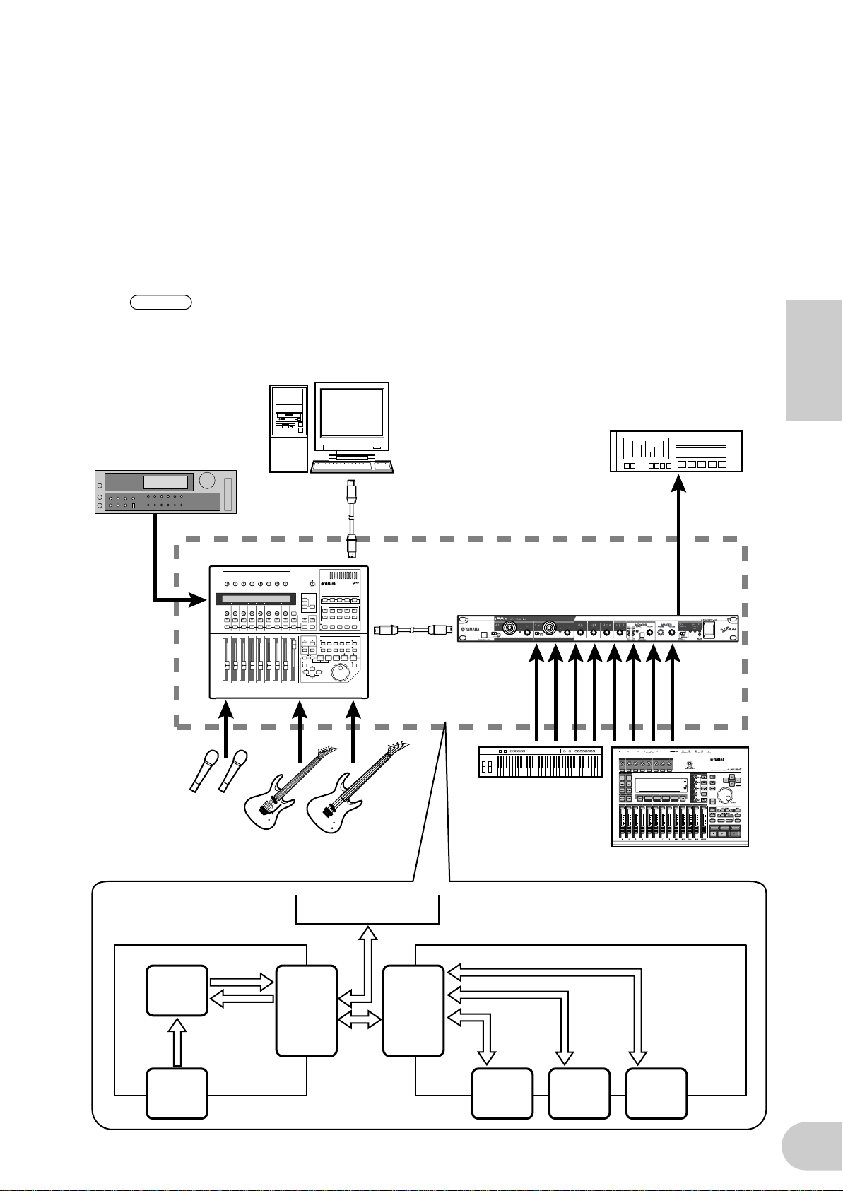
2. Verwendung mehrerer mLAN-Geräte
Verbinden Sie den mLAN-Anschluss (IEEE 1394) des entsprechend ausgestatteten Computers und den
mLAN-Anschluss am Digital Mixing Studio 01X und am i88X mit den passenden IEEE-1394-Kabeln.
Routen Sie in der mLAN Graphic Patchbay (lesen Sie darüber in der Online-Anleitung der mLAN
Graphic Patchbay) die Audio- und MIDI-Signale zwischen dem Computer und dem i88X wie
gewünscht und stellen Sie die Wordclock ein.
Mit diesem System können Sie die digitalen Mischfunktionen des 01X voll ausnutzen
(Digitalmischung von bis zu 28 Kanälen). Unter Einsatz von acht A/D-Eingängen am 01X und acht A/
D-Eingängen am i88X können Sie 16 Kanäle analoger Audiodaten an den 01X übertragen. Es stehen
acht D/A-Ausgänge am i88X zur Verfügung, sowie der MONITOR OUT (in stereo) und der STEREO/
AUX OUT (in stereo) am 01X. Die analogen Schnittstellen und die Buchsen COAXIAL und OPTICAL
DIGITAL STEREO am i88X erweitern die analogen und digitalen Ein- und Ausgänge des 01X.
HINWEIS
Die Anzahl der verfügbaren Ein- und Ausgangskanäle kann je nach den angeschlossenen mLANGeräten variieren. Zum Erreichen der besten Netzwerkleistung wird empfohlen, an ein Netzwerk
bis zu vier mLAN-Geräte (einschließlich Computer) anzuschließen. Wenn das Netzwerk ein
mLAN-Gerät enthält, das nur mit einer niedrigen Übertragungsrate kompatibel ist (200 Mbps
(S200)), verringert sich die Anzahl der für eine Verbindung verfügbaren Geräte und Kanäle.
IEEE-1394-kompatibler
Computer
ADAT-Recorder
Deutsch
Sampler
Mikrofone
01X
Gitarre
ADAT
IEEE-1394-Kabel
i88X
Synthesizer
Bass
Mehrspurrekorder
Computer
01X i88X
mLAN OUT
1-16ch
MISCHPULT
mLAN IN
1-18ch
INPUT
1-8
mLAN
IN/OUT
mLAN
IN/OUT
mLAN
IN/OUT
1-8ch
INPUT/
OUTPUT
1-8
mLAN
IN/OUT
9-10ch
DIGITAL
STEREO
IN/OUT
mLAN IN/OUT
11-18ch
(44,1kHz/48kHz)
11-14ch
(88,2kHz/96kHz)
ADAT
IN/OUT
19
Page 44
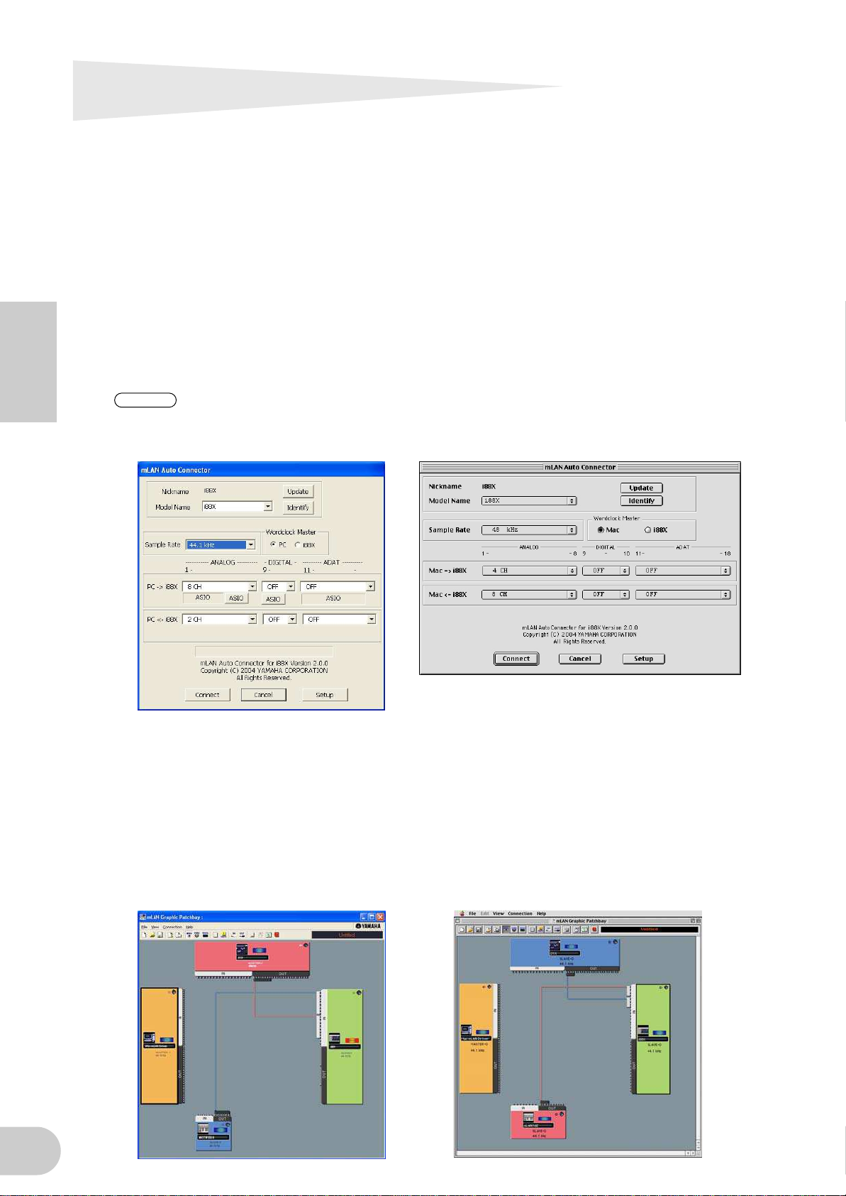
Herstellen von mLAN-Verbindungen
In einem mLAN-System können Sie mithilfe der Softwareanwendungen mLAN Graphic Patchbay und
mLAN Auto Connector ganz unkompliziert das System konfigurieren und pflegen, die Buchsen am
Computer und den einzelnen mLAN-Geräten (virtuelle Ein- und Ausgangsbuchsen für Audio-/MIDISignale) anschließen und abtrennen und verschiedene mLAN-Verbindungseinstellungen wie z.B. die
Synchronisation vornehmen. Sie brauchen keine Audio- oder MIDI-Kabel umzustecken, um in
verschiedenen Musikproduktions-Umgebungen arbeiten zu können.
mLAN Auto Connector
Mithilfe dieser Softwareanwendung können Sie einen Computer an ein einziges mLAN-Gerät
anschließen.
Dies ermöglicht Ihnen die bequeme Auswahl der Wordclock sowie der Ein- und Ausgangskanäle für
die Audiosignale.
Informationen zur Installation und Verwendung der Software finden Sie im separaten
Installationshandbuch.
Deutsch
HINWEIS
Sie können mLAN Graphic Patchbay auch verwenden, um einen Computer mit einem einzigen
mLAN-Gerät zu verbinden.
Windows Macintosh
mLAN Graphic Patchbay
Mit dieser Grafiksoftware können Sie die mLAN-Verbindungseinstellungen des angeschlossenen
Computers und mehrerer mLAN-Geräte verwalten. Sie können die Verbindungen sofort in ihrer
Gesamtheit erfassen, wenn Sie sich die angezeigten Grafiken mit der mLAN-Systemkonfiguration
ansehen. Außerdem haben Sie die Möglichkeit, die Wordclock-Einstellungen und Signalführung der
Audio- und MIDI-Signale intuitiv zu ändern, ganz ähnlich wie beim Anschließen physischer Kabel.
Informationen zur Installation und Verwendung der Software finden Sie im separaten
Installationshandbuch und in der Online-Anleitung der mLAN Graphic Patchbay.
Windows Macintosh
20
Page 45

LED-Anzeigen
Anzeigen Status Bedeutung
ACTIVE Stetig blau
leuchtend
Aus Im mLAN-Betrieb ist ein Fehler aufgetreten.
MASTER CLOCK INT Stetig grün
leuchtend
ADAT Stetig grün
leuchtend
Grün blinkend Das i88X synchronisiert nicht zum Wordclock Master
mLAN Stetig grün
leuchtend
Grün blinkend Das i88X synchronisiert nicht zum Wordclock Master
MONITOR
/Sampling Rate
1/2 (44k) Stetig rot
leuchtend
Rot blinkend Das i88X verwendet eine Sampling-Frequenz von
3/4 (48k) Stetig rot
leuchtend
Das i88X funktioniert als normales mLAN-Gerät.
Das i88X verwendet die INTERNAL-Sampling-Frequenz
von 44,1 kHz.
Das i88X synchronisiert zum Wordclock Master
(ADAT).
(ADAT).
Das i88X synchronisiert zum Wordclock Master
(ADAT).
(ADAT).
CH 1&2 sind zum Abhören ausgewählt.
44,1 kHz.
CH 3&4 sind zum Abhören ausgewählt.
Deutsch
Rot blinkend Das i88X verwendet eine Sampling-Frequenz von
5/6 (88k) Stetig rot
leuchtend
Rot blinkend Das i88X verwendet eine Sampling-Frequenz von
7/8 (96k) Stetig rot
leuchtend
Rot blinkend Das i88X verwendet eine Sampling-Frequenz von
DIGITAL Stetig rot
leuchtend
PEAK Stetig rot
leuchtend
HINWEIS
Wenn Sie die Taste [SELECT] drücken und länger als eine Sekunde halten, blinkt die Anzeige
MONITOR/Sampling Rate für die momentane Sampling-Frequenz (44k, 48k, 88k oder 96k) rot.
48 kHz.
CH 5&6 sind zum Abhören ausgewählt.
88 kHz.
CH 7&8 sind zum Abhören ausgewählt.
96 kHz.
DIGITAL ist zum Abhören ausgewählt.
Das analoge Eingangssignal hat den Spitzenpegel
erreicht.
21
Page 46

Falls ein Problem auftritt…
Wenn Sie keinen Ton oder einen merkwürdigen Ton hören, überprüfen Sie zunächst die nachstehend
beschriebenen Punkte, und ergreifen Sie sodann geeignete Maßnahmen. Sollte das Problem weiter
bestehen, wenden Sie sich an Ihre Yamaha-Vertragshändler.
■
Deutsch
■
■
22
Fehlerbehebung
Kein Ton oder nur sehr leise Tonausgabe
• Haben Sie die Lautsprecher/den Kopfhörer richtig angeschlossen?
• Haben Sie den Verstärker und die anderen externen Geräte eingeschaltet?
• Sendet die externe Quelle überhaupt ein Signal?
• Vielleicht ist das Audiokabel der externen Signalquelle defekt.
• Haben Sie sowohl am i88X als auch auf dem/den externen Gerät(en) die richtigen Wordclock-Einstellungen
gewählt?
.............Lesen Sie hierzu den Abschnitt „Anschließen des Computers an ein mLAN-Gerät über mLAN“
im Installationshandbuch und den Abschnitt „Wordclock-Einstellungen“ in der OnlineAnleitung der mLAN Graphic Patchbay.
• Sind alle Lautstärkepegel (für alle Klangerzeuger, Wiedergabegeräte und für die Anwendung selbst) in geeigneter
Weise eingestellt?
• (Für Windows) Ist mLAN (mLAN Driver) aktiviert („ON“)? Klicken Sie mit der rechten Maustaste auf das mLANManager-Symbol in der Taskleiste.
• Sind alle anderen mLAN-Einstellungen sinnvoll?
.............Lesen Sie „Die Kommunikation über mLAN ist nicht möglich“ (Seite 23).
• Wenn mehr als vier Geräte (einschließlich Computer) an das Netzwerk angeschlossen sind, wurde
möglicherweise die Bandbreitengrenze des IEEE1394-Bus überschritten.
• Möglicherweise wurde die Bandbreitengrenze des IEEE-1394-Bus überschritten. Überprüfen Sie mithilfe von
mLAN Graphic Patchbay die aktuelle Bandbreite, und trennen Sie, falls erforderlich, eines oder mehrere Geräte ab.
.............Lesen Sie hierzu den Abschnitt „Menüleiste“ in der Online-Anleitung der mLAN Graphic
Patchbay.
• Wenn an das mLAN-Netzwerk ein mLAN-Gerät angeschlossen ist, das nur S200 unterstützt, wird dadurch
möglicherweise die Bandbreite des IEEE-1394-Bus verringert und seine Grenze überschritten. Verringern Sie die
Anzahl der an das Netzwerk angeschlossenen mLAN-Geräte, oder trennen Sie nach Bedarf eines oder mehrere
Geräte ab.
.............Lesen Sie hierzu den Abschnitt „Menüleiste“ in der Online-Anleitung der mLAN Graphic
Patchbay.
Verzerrter Ton
• Haben Sie den [GAIN]-Regler ordnungsgemäß eingestellt?
.............Lesen Sie weiter auf Seite 16.
• Vielleicht ist das Audiokabel der externen Signalquelle defekt.
• Haben Sie sowohl am i88X als auch auf dem/den externen Gerät(en) die richtigen Wordclock-Einstellungen
gewählt?
.............Lesen Sie hierzu den Abschnitt „Anschließen des Computers an ein mLAN-Gerät über mLAN“
im Installationshandbuch und den Abschnitt „Wordclock-Einstellungen“ in der OnlineAnleitung der mLAN Graphic Patchbay.
• Vergewissern Sie sich, dass die Audiodaten mit einem geeigneten Lautstärkepegel aufgenommen wurden.
Hörbare Störgeräusche
• Ist die Latenzzeit des mLAN Driver richtig eingestellt?
.............Lesen Sie hierzu die Abschnitte „mLAN Driver Setup“ und „ASIO mLAN Control Panel“ im
Installationshandbuch.
• (Für Windows) Die Lösung des Problems kann darin bestehen, in den BIOS-Einstellungen das Hyper-Threading
zu deaktivieren.
• Haben Sie sowohl am i88X als auch auf dem/den externen Gerät(en) die richtigen Wordclock-Einstellungen
gewählt?
.............Lesen Sie hierzu den Abschnitt „Anschließen des Computers an ein mLAN-Gerät über mLAN“
im Installationshandbuch und den Abschnitt „Wordclock-Einstellungen“ in der OnlineAnleitung der mLAN Graphic Patchbay.
• Wenn die Geschwindigkeit der Festplatte Ihres Computers langsam ist, können Probleme bei der Aufnahme und
Wiedergabe auftreten.
• Wenn Sie bei Verwendung von mLAN die mLAN-, USB- oder sonstigen Kabel von den Minibuchsen des
Macintosh abziehen bzw. daran anschließen, können Störgeräusche auftreten und/oder Daten abgeschnitten
werden. Achten Sie darauf, während der Verwendung von mLAN keine Verbindungen herzustellen oder zu
unterbrechen.
• Ist die Anzahl der Audiokanäle geeignet? Wie viele Audiokanäle gleichzeitig genutzt werden können, hängt von
der Kapazität und Geschwindigkeit des Computers ab.
.............Lesen Sie hierzu den Abschnitt „Anschließen des Computers an ein mLAN-Gerät über mLAN“
im Installationshandbuch und den Abschnitt „Wordclock-Einstellungen“ in der OnlineAnleitung der mLAN Graphic Patchbay.
Page 47

• Ist die Sampling-Rate (Wordclock) in geeigneter Weise eingestellt? Je nach Kapazität und Geschwindigkeit des
Computer
Computer
i88X
i88X
: Gerät mit IEEE-1394-Schnittstelle
Computers kann eine hohe Sampling-Rate die Ursache der Störgeräusche sein.
.............Lesen Sie hierzu den Abschnitt „Anschließen des Computers an ein mLAN-Gerät über mLAN“
im Installationshandbuch und den Abschnitt „Wordclock-Einstellungen“ in der OnlineAnleitung der mLAN Graphic Patchbay.
• Stellen Sie sicher, dass nicht zu viele Geräte an den Computer angeschlossen sind. Je nach der Auslastung des
Computers könnten die Geräusche durch Anschluss zu vieler Geräte verursacht werden.
• Befinden sich in der Nähe der Kabel Geräte, die Störgeräusche verursachen (z.B. Geräte mit Wechselrichtern
usw.)? Legen Sie alle Kabel entfernt von möglichen Störgeräuschquellen.
• Vergewissern Sie sich, dass das mLAN-Kabel unbeschädigt ist. Kabel, die nicht die IEEE-1394-Standards erfüllen,
können Störgeräusche verursachen.
• Lassen Sie im Hintergrund keine Anwendungen wie z.B. Anti-Virus-Software laufen. Deaktivieren Sie, wenn Sie
das mLAN-System verwenden, alle Anwendungen, die im Hintergrund laufen. Wenn diese Anwendungen aktiv
bleiben, kann es sein, dass der Treiberbetrieb instabil wird und Störgeräusche verursacht. Wenn Sie nicht
vorhaben, das mLAN-System zu verwenden, können Sie diese Anwendungen aktivieren. (Sie können den mLANTreiber mithilfe von mLAN Manager ein- und ausschalten.)
■
Zu wenige Spuren für Aufnahme oder Wiedergabe
• Ist die Anzahl der (in mLAN Auto Connector und mLAN Graphic Patchbay eingestellten) mLAN-Audioempfangsund -sendekanäle korrekt?
.............Lesen Sie hierzu den Abschnitt „Anschließen des Computers an ein mLAN-Gerät über mLAN“
im Installationshandbuch und den Abschnitt „Wordclock-Einstellungen“ in der OnlineAnleitung der mLAN Graphic Patchbay.
■
Die Übertragung von MIDI-Daten oder Programmwechseln nicht möglich
• Stimmen die MIDI-Verbindungen?
• Vielleicht ist ein/das MIDI-Kabel defekt.
• Haben Sie alle Sende- und Empfangsgeräte eingeschaltet?
• Stellen Sie sicher, dass Sende- und Empfangskanal richtig zugeordnet sind.
■
Falsche Tonhöhe
• Arbeitet das i88X mit derselben Sampling-Frequenz wie das synchronisierte externe Gerät?
.............Lesen Sie hierzu den Abschnitt „Anschließen des Computers an ein mLAN-Gerät über mLAN“
im Installationshandbuch und den Abschnitt „Wordclock-Einstellungen“ in der OnlineAnleitung der mLAN Graphic Patchbay.
• Läuft der Taktgeber stabil?
■
Die Kommunikation über mLAN ist nicht möglich
• Wurde der Treiber installiert?
.............Einzelheiten finden Sie in der Installationsanleitung.
• Ist das mLAN-Kabel richtig angeschlossen? Prüfen Sie die Verbindung; ziehen Sie das mLAN-Kabel einmal ab,
und schließen es erneut an.
• (Für Windows) Ist mLAN eingeschaltet („ON“)? Klicken Sie in der Taskleiste mit der rechten Maustaste auf das
mLAN-Manager-Symbol.
.............Siehe „Bestätigen der Installation“ in der Installationsanleitung.
• (Für Windows) Wenn Sie eine neue IEEE-1394-Karte einsetzen, klicken Sie in der Taskleiste mit der rechten
Maustaste auf das mLAN-Manager-Symbol, und wählen Sie „ON“.
.............Siehe „Bestätigen der Installation“ in der Installationsanleitung.
• Leuchtet die Statusanzeige auf der Rückseite des i88X blau? Wenn nicht, überprüfen Sie Folgendes:
- Leuchtet die Statusanzeige im mLAN Driver Setup blau? Wenn nicht starten Sie das i88X erneut, und
reaktivieren Sie die Verbindung mithilfe von mLAN Auto Connector oder mLAN Graphic Patchbay.
.............Lesen Sie hierzu den Abschnitt „Einstellungen nach der Installation ändern“ in der
Installationsanleitung und der Online-Anleitung zur mLAN Graphic Patchbay.
• Wurde die Verbindung mit mLAN Auto Connector und/oder Graphic Patchbay aktiviert? Reaktivieren Sie die
Verbindung falls nötig.
.............Lesen Sie hierzu den Abschnitt „Anschließen des Computers und der mLAN-Geräte über
mLAN“ im Installationshandbuch und den Abschnitt „mLAN-Verbindungseinstellungen“ in
der Online-Anleitung der mLAN Graphic Patchbay.
• Haben Sie das Gerät ausgetauscht? Selbst wenn das Modell dasselbe, das Gerät aber ein anderes ist, muss die
Verbindung mithilfe von Auto Connector und/oder Graphic Patchbay reaktiviert werden.
.............Lesen Sie hierzu den Abschnitt „Anschließen des Computers und der mLAN-Geräte über
mLAN“ im Installationshandbuch und den Abschnitt „mLAN-Verbindungseinstellungen“ in
der Online-Anleitung der mLAN Graphic Patchbay.
• Besteht eine Ringverbindung? Prüfen Sie die Verkabelung und stellen Sie sicher, dass die Geräte nicht in einer
Schleife miteinander verbunden sind.
Deutsch
23
Page 48

■
Deutsch
■
■
■
■
■
■
■
24
• Möglicherweise hat die IEEE-1394-Schnittstelle Ihres Computers eine Grenze bezüglich der gleichzeitig
nutzbaren Ports. Prüfen Sie, wie viele Ports gleichzeitig benutzt werden können.
• Schalten Sie alle Geräte auf dem mLAN-Netzwerk (mit Ausnahme des Computers) aus, und schließen Sie
nacheinander die Geräte wieder an, bis dasjenige Gerät gefunden ist, welches das Problem verursacht.
• (Für Windows) (Wenn Sie den mLAN-Bus aus der Einstellung [Hardware sicher entfernen] der Taskleiste
entfernen.) Starten Sie den Computer neu, wenn Sie mLAN wieder benutzen möchten.
• Bei den Apple-Notebooks iBook und PowerBook sollten Sie immer zuerst das i88X und das mLAN-Kabel
anschließen und dann das i88X einschalten, bevor Sie den Computer starten.
Der mLAN-Treiber (MIDI/Audio) wird von einer Anwendung wie z.B. einer DAW nicht erkannt
• (Für Windows) Vergewissern Sie sich, dass mLAN nicht ausgeschaltet wurde. Klicken Sie in der Taskleiste mit der
rechten Maustaste auf mLAN Manager ( ), und wählen Sie dann die Option „ON“ (Ein).
.............Lesen Sie hierzu den Abschnitt „Bestätigen der Installation“ im Installationshandbuch und
den Abschnitt „mLAN-Verbindungseinstellungen“ in der Online-Anleitung der mLAN
Graphic Patchbay.
• Vergewissern Sie sich, dass das i88X mit dem mLAN-Kabel verbunden und eingeschaltet ist. Starten Sie mLAN
Auto Connector oder mLAN Graphic Patchbay, und schließen Sie das Gerät dann erneut an.
.............Lesen Sie hierzu den Abschnitt „Bestätigen der Installation“ im Installationshandbuch und
den Abschnitt „mLAN-Verbindungseinstellungen“ in der Online-Anleitung der mLAN
Graphic Patchbay.
• (Für Macintosh) Um im System ein iBook oder PowerBook zu verwenden, schließen Sie das i88X mithilfe eines
mLAN-Kabels an den Macintosh an, schalten Sie das i88X ein, und starten Sie dann den Macintosh.
• Stellen Sie sicher, dass alle anderen mLAN-Einstellungen richtig sind. Lesen Sie „Die Kommunikation über mLAN
ist nicht möglich“ (Seite 23).
Die Verarbeitungsgeschwindigkeit des Computers ist zu langsam
Das CPU-Meter des Computers zeigt eine hohe Verarbeitungslast an
Die Wiedergabe erfolgt verzögert
• Vergewissern Sie sich, dass der Computer die Systemanforderungen erfüllt.
.............Lesen Sie hierzu den Abschnitt „Systemanforderungen“ im Installationshandbuch.
• (Für Windows) Wenn Sie das mLAN-System nicht verwenden, klicken Sie in der Taskleiste mit der rechten
Maustaste auf mLAN Manager ( ), und wählen Sie dann die Option „OFF“ (Aus; mLAN wird beendet).
.............Lesen Sie auch „Bestätigen der Installation“ in der Installationsanleitung.
• Versuchen Sie es damit, im mLAN Auto Connector oder in der Graphic Patchbay die Anzahl der Audiokanäle zu
verringern.
.............Lesen Sie hierzu den Abschnitt „Anschließen des Computers und der mLAN-Geräte über
mLAN“ im Installationshandbuch und den Abschnitt „mLAN-Verbindungseinstellungen“ in
der Online-Anleitung der mLAN Graphic Patchbay.
• Versuchen Sie es damit, den Wert für die Latenzzeit zu erhöhen.
.............Lesen Sie hierzu den Abschnitt „Ändern der Einstellungen nach der Installation“ im
Installationshandbuch.
• (Für Macintosh) Wenn ein Modell mit zwei CPUs den Schlaf- oder Standby-Modus verlässt, kann die
Verarbeitungsgeschwindigkeit verlangsamt sein. Starten Sie in diesem Fall den Computer neu.
• (Für Windows) Lesen Sie hierzu die „Tipps für den Einsatz von Audiodaten (Windows)“.
.............Einzelheiten finden Sie in der Installationsanleitung.
• (Für Windows) Eine Verbesserung kann erreicht werden, wenn Sie das Hyper Threading deaktivieren.
• Versuchen Sie es damit, in mLAN Graphic Patchbay die Anzahl der an den Computer angeschlossenen Geräte zu
verringern.
.............Lesen Sie hierzu den Abschnitt „mLAN-Verbindungseinstellungen“ in der Online-Anleitung
der mLAN Graphic Patchbay.
• (Für Macintosh) Schalten Sie den virtuellen Speicher aus.
• (Für Macintosh) Deaktivieren Sie AppleTalk.
Inkonsistenz in der Wordclock, oder Beenden des Auto Connector nicht möglich
• (Für Windows) Mobilcomputer mit Intel CPU
SpeedStep™-Technik wird bei einigen CPUs angewendet (CPUs für Notebook-Computer). Bitte deaktivieren Sie
die SpeedStep™-Technik, wenn mLAN benutzt wird. Die SpeedStep™-Technik ändert die CPU-Clock dynamisch
abhängig von der CPU-Last, um den Stromverbrauch zu senken.
- Deaktivieren der SpeedStep™-Technik;
In fast allen PCs gibt es eine Einstellung im BIOS, mit der die SpeedStep™-Technik ein- und
ausgeschaltet werden kann. Bitte lesen Sie hierzu die Bedienungsanleitung Ihres Computers, oder fragen
Sie beim Hersteller nach.
Das Schließen der Anwendung bzw. das Herunterfahren des Betriebssystems ist nicht möglich
Das Ändern der mLAN-Einstellungen ist nicht möglich
Die Deinstallation der mLAN Applications for Yamaha oder der mLAN Tools 2.0 ist nicht möglich
• (Für Windows) Ist der mLAN- (WDM-) Treiber als das standardmäßige Audiogerät für das System ausgewählt?
- Wählen Sie [Start | Systemsteuerung | Sounds und Audiogeräte | Voice].
Vergewissern Sie sich, dass unter [Stimmenwiedergabe] und [Stimmenaufnahme] nicht „mLAN Audio
01“ ausgewählt ist.
Page 49

- Wählen Sie [Start | Systemsteuerung | Sounds und Audiogeräte | Audio].
Vergewissern Sie sich, dass unter [Soundwiedergabe] und [Soundaufnahme] nicht „mLAN Audio 01“
ausgewählt ist.
• (Für Windows) Wählen Sie [Start | Systemsteuerung | Sounds und Audiogeräte | Audio]. Wählen Sie außerdem
als [Soundschema] die Option „Keine Sounds“, und führen Sie den Vorgang dann erneut aus.
• Wenn Sie mLAN nicht beenden können (indem Sie in der Taskleiste mit der rechten Maustaste auf das mLANManager-Symbol klicken und „OFF“ (Aus) auswählen), beenden Sie die unten aufgeführten Anwendungen
manuell. ([Strg] + [Alt] + [Entf] → [Anwendung schließen] → Task auswählen → [Task beenden]). Starten Sie
nach dem Beenden der Anwendungen mLAN Manager, um die mLAN-Einstellungen wieder zu ändern.
- mLANVDevice.exe
- mLANTFamily.exe
- mLANSoftPH.exe
- mLANManager.exe
Um mLAN-Einstellungen zu ändern, wählen Sie [Start | (Alle) Programme | Autostart], und starten Sie dann
mLAN Manager.
- (Wenn bei der Deinstallation eine Meldung wie „Datei wurde nicht gefunden“ erscheint:)
Führen Sie erneut eine Installation aus, und versuchen Sie nochmals die Deinstallation.
■
(Windows) Der mLAN Manager (das mLAN-Symbol in der Taskleiste) ist verschwunden
• Wählen Sie [Start | (Alle) Programme | Autostart (oder mLAN Tools)], und wählen Sie dann mLAN Manager.
Technische Daten
Deutsch
■ Allgemeine technische Daten
Sampling-Frequenz Internal, External
Frequenzgang
Gesamte Harmonische
Verzerrungen (THD)
Dynamikumfang 110 dB Line-Eingang an Master-Ausgang L/R (Kanal 1/2) oder Kanal 3–8
Rauschpegel –100 dBu (Ausgabelautstärke: Min.), –90 dBu (Ausgabelautstärke: Max.)
Übersprechen 75 dB 1 kHz
A/D-Wandler
D/A-Wandler
Schnittstellenfunktionen
Kompatible mLANÜbertragungsrate
mLAN Audio-Schnittstellen
Fs 44,1 kHz, 48 kHz 20 Hz bis 20 kHz
Fs 88,2 kHz, 96 kHz 20 Hz bis 40 kHz
Geringer als
0,01%
24-Bit linear, 128-faches Oversampling (Fs 44,1, 48 kHz) / 64-faches Oversampling
(Fs 88,2, 96 kHz)
24-Bit linear, 128-faches Oversampling (Fs 44,1, 48 kHz) / 64-faches Oversampling
(Fs 88,2, 96 kHz)
S400 (400Mbps) / S200 (200Mbps)
18 Kan. Eingänge / 18 Kan. Ausgänge (Fs 44,1 kHz, 48 kHz)
Art: Eingänge (analog) 8 Kan., digitale Eingänge 2 Kan., ADAT-Eingänge 8 Kan.
14 Kan. Eingänge / 14 Kan. Ausgänge (Fs 88,2 kHz, 96 kHz)
Art: Eingänge (analog) 8 Kan., digitale Eingänge 2 Kan., ADAT-Eingänge 4 Kan.
MIDI-Schnittstellen 1 Eingangsbuchse / 1 Ausgangsbuchse
Normale Sampling-Frequenz (Fs) 44,1 kHz (–10%) bis 48 kHz (+6%)
Doppelte Sampling-Frequenz 88,2 kHz (–10%) bis 96 kHz (+6%)
0 +1/–3 dB, vom INPUT zum MASTER OUTPUT L/R (Fs 48 kHz, MIC/
LINE)
0 +1/–3 dB, vom INPUT zum MASTER OUTPUT L/R (Fs 96 kHz, MIC/
LINE)
1 kHz, LINE-Eingang zum MASTER OUTPUT L/R (Input Gain = Min.,
Ausgabelautstärke = Max.)
*1
■ Technische Daten der Ein- und Ausgänge
Analogeingänge
INPUT 1,2
INPUT 3–8
INSERT IN 1–2
Kombination XLR/TRS-Klinke
Symmetrisch, +48V ±3V
Phantomspeisung,
Mic/Line/Hi-Z
TRS-Klinke
TRS-Klinke
Anschlusstyp
*3
, Symmetrisch, Line
*4
, Unsymmetrisch
*2
–60 dBu bis –16 dB (Mic) –2 dBu
,
–34 dBu bis +10 dBu (Line) +24 dBu
–56 dBu bis +12 dBu (Hi-Z) +2 dBu 500 kΩ
Eingangspegel
Nennwert
–20 dBu bis +10 dBu +24 dBu 10 kΩ
–2 dBu +12 dBu 10 kΩ
Max. vor
Verzerrung
Eingangsimpedanz
3 kΩ
25
Page 50

Analogausgänge
OUTPUT 1–8
(MASTER OUT L/R)
INSERT OUT 1–2
PHONES
(Kopfhörer)
Anschlusstyp
TRS-Klinke, Symmetrisch
*4
TRS-Klinke
TRS-Stereoklinke
, Unsymmetrisch
Ausgangspegel
Nennwert
*3
+4 dBu +18 dBu 2 kΩ (10 kΩ)
Max. vor
Verzerrung
Tatsächliche
Lastimpedanz
(Nennlastimpedanz)
–2 dBu +12 dBu 600 Ω (10 kΩ)
— 100 mW +100 mW 33 kΩ (33 kΩ)
Digitaleingänge
/-ausgänge
ADAT/DIGITAL
OPTICAL IN, OUT
DIGITAL STEREO
IN, OUT
Deutsch
MIDI IN, OUT A/B DIN 5-Pol MIDI
mLAN 1/2 IEEE 1394 6-Pol mLAN
Anschlusstyp Format
*5
ADAT
OPTICAL
Cinch
IEC-60958 ConsumerFormat (DIGITAL)
IEC-60958 ConsumerFormat
Empfohlener
Ausgangspegel
—
—
0,5 Vpp/75 Ω
—
—
Weitere Einzelheiten
Unterstützt DOUBLE (bis zu 96 kHz)
Die Buchse IN besitzt einen
integrierten Sampling Rate Converter.
Kompatibel mit S400 und S200
*1: Vom ADAT-kompatiblen Gerät eingegebenes Signal: Normale Sampling-Frequenz (Fs) 44,1 kHz (-6%) bis 48 kHz (+6%)
Doppelte Sampling-Frequenz 88,2 kHz (-6%) bis 96 kHz (+6%)
*2: Immer symmetrisch, unabhängig von der Verwendung von XLR-3-31 oder TRS-Klinke. (1=MASSE, 2=HEISS, 3=KALT/
Spitze=HEISS, Ring=KALT, Mantel=MASSE)
*3: Symmetrische Klinke (Spitze=HEISS, Ring=KALT, Mantel=MASSE)
*4: INSERT IN & OUT sind als unsymmetrische Klinkenbuchsen ausgeführt. (Spitze=AUSGANG, Ring=EINGANG,
Mantel=MASSE)
*5: Proprietäres, optisches, digitales Mehrkanal-Schnittstellenformat von ALESIS
Wenn „dBu“ für eine bestimmte Spannung steht, entspricht 0 dBu dem Wert 0,775 Vrms.
■ Bedienungselemente
Eingangsverstärkung (Gain) Gain-Regler 1, 2, 3, 4, 5/6, 7/8
Phantomschalter Phantomspannung (+48 V) Ein/Aus für Eingangskanäle 1, 2 mit LED *5
Gain-Schalter (PAD; Absenkung) Eingang Kan. 1: Mic/Line/Hi-Z, Eingang Kan. 2: Mic/Line
Peak-LED (Spitzenpegel) Eingangskanäle 1, 2
Monitor-Wahlschalter (Anzeige der
Sampling-F.)
Monitor-LED (Fs-Anzeige)
Monitor-Lautstärkeregelung Direct-Monitoring-Lautstärke für den mit dem Monitor-Schalter ausgewählten Kanal
Master Volume (Gesamtlautstärke) Ausgangspegel der Ausgänge MASTER OUTPUT L/R und PHONES
Optical-Auswahlschalter Digital / ADAT Normal / ADAT Double
Master-Clock-LED mLAN / ADAT / Internal (fixiert auf 44,1 kHz)
mLAN-Aktivitäts-LED Zur Information zum mLAN-Status
Netzschalter Schalter Bereitschaft/Ein
*5: Phantomspannung (+48 V) wird nicht geliefert, wenn die TRS-Klinkeneingänge genutzt werden. Wenn der Schalter [HI-Z/LINE/
MIC] auf HI-Z steht, wird keine Phantomspannung an die INPUT-Buchse 1 geliefert.
Direct-Monitoring-Kanalauswahlschalter: 1/2, 3/4, 5/6, 7/8, Digitaleingang /
Fs-Anzeige (eine Weile gedrückt halten)
Direct-Monitoring-Kanalauswahlschalter: 1/2, 3/4, 5/6, 7/8, Digitaleingang /
Fs-Anzeige: 44,1, 48, 88,2, 96 kHz
26
■ Sonstiges
Mitgeliefertes Zubehör
Leistungsaufnahme 16 W
Abmessungen 480 (B) x 372,7 (T) x 44 (H) mm
Gewicht 3,9 kg
Netzadapter (PA-5D), ein Satz Bedienungsanleitungen, CD-ROM x 2, mLAN-Kabel
(IEEE 1394)
* Die in dieser Bedienungsanleitung enthaltenen technischen Daten und Beschreibungen dienen
lediglich der Information. Yamaha Corp. behält sich das Recht vor, Produkte oder technische Daten
jederzeit ohne vorherige Ankündigung zu ändern oder zu modifizieren. Da die technischen Daten, das
Gerät selbst oder das Zubehör nicht in jedem Land gleich sind, setzen Sie sich im Zweifelsfall bitte mit
Ihrem Yamaha-Händler in Verbindung.
Page 51

PRECAUTIONS D'USAGE
Avertissement en cas de présence d'eau
Avertissement en cas de feu
En cas d'anomalie
Emplacement
PRIERE DE LIRE ATTENTIVEMENT AVANT DE PROCEDER
A TOUTE MANIPULATION
* Rangez soigneusement ce manuel pour pouvoir le consulter ultérieurement.
AVERTISSEMENT
Veillez à toujours observer les précautions élémentaires énumérées ci-après pour éviter de graves blessures, voire
la mort, causées par l'électrocution, les courts-circuits, dégâts, incendie et autres accidents. La liste des
précautions données ci-dessous n'est pas exhaustive :
Alimentation/adaptateur secteur CA
• Utilisez seulement la tension requise par l'instrument. Celle-ci est imprimée
sur la plaque du constructeur de l'instrument.
• Utilisez seulement l'adaptateur spécifié (PA-5D ou un adaptateur équivalent
conseillé par Yamaha). L'emploi d'un mauvais adaptateur risque
d'endommager l'instrument ou d'entraîner une surchauffe.
• Vérifiez périodiquement l'état de la prise électrique, dépoussiérez-la et nettoyezla.
• Ne laissez pas l’adaptateur CA d'alimentation à proximité des sources de
chaleur, telles que radiateurs et appareils chauffants. Evitez de tordre et plier
excessivement le cordon ou de l'endommager de façon générale, de même que
de placer dessus des objets lourds ou de le laisser traîner là où l’on marchera
dessus ou se prendra les pieds dedans ; ne déposez pas dessus d'autres câbles
enroulés.
Ne pas ouvrir
• N’ouvrez pas l'instrument, ni tenter d'en démonter les éléments internes ou de
les modifier de quelque façon que ce soit. Aucun des éléments internes de
l'instrument ne prévoit d'intervention de l'utilisateur. Si l'instrument donne
des signes de mauvais fonctionnement, mettez-le immédiatement hors
tension et donnez-le à réviser au technicien Yamaha.
• Evitez de laisser l'instrument sous la pluie, de l'utiliser près de l'eau, dans
l'humidité ou lorsqu'il est mouillé. N’y déposez pas des récipients contenant
des liquides qui risquent de s'épancher dans ses ouvertures.
• Ne touchez jamais une prise électrique avec les mains mouillées.
• Ne déposez pas d'articles allumés, tels que des bougies, sur l'appareil. Ceuxci pourraient tomber et provoquer un incendie.
• Si le cordon de l'adaptateur CA s'effiloche ou est endomagé ou si vous
constatez une brusque perte de son en cours d'interprétation, ou encore si
vous décèlez une odeur insolite, voire de la fumée, coupez immédiatement
l'interrupteur principal, retirez la fiche de la prise et donnez l'instrument à
réviser par un technicien Yamaha.
Français
ATTENTION
Veillez à toujours observer les précautions élémentaires ci-dessous pour éviter à soi-même et à son entourage des
blessures corporelles, de détériorer l'instrument ou le matériel avoisinant. La liste de ces précautions n'est pas
exhaustive
Alimentation/adaptateur secteur CA
• Veillez à toujours saisir la fiche elle-même, et non le câble, pour la retirer de
l'instrument ou de la prise d'alimentation.
• Débranchez l'adaptateur secteur dès que vous n'utilisez plus l'instrument ou
en cas d'orage (éclairs et tonnerre).
• N’utilisez pas de connecteur multiple pour brancher l'instrument sur une prise
électrique du secteur. Cela risque d'affecter la qualité du son ou
éventuellement de faire chauffer la prise.
:
• N’abandonnez pas l'instrument dans un milieu trop poussiéreux ou un local
soumis à des vibrations. Evitez également les froids et chaleurs extrêmes
(exposition directe au soleil, près d'un chauffage ou dans une voiture exposée
en plein soleil) qui risquent de déformer le panneau ou d'endommager les
éléments internes.
• N’utilisez pas l'instrument à proximité d'une TV, d'une radio, d'un équipement
stéréo, d'un téléphone portable ou d'autres appareils électriques. En effet,
l'instrument, la TV ou la radio pourraient produire des interférences.
• N’installez pas l'instrument dans une position instable où il risquerait de se
renverser.
• Débranchez tous les câbles connectés, y compris celui de l'adaptateur, avant
de déplacer l'instrument.
• Utilisez le bâti indiqué pour l'instrument. Pour la fixation du pied ou du bâti,
utilisez seulement les vis fournies par le fabricant, faute de quoi vous risquez
d'endommager les éléments internes ou de voir se renverser l'instrument.
(3)-7 1/2
3
Page 52
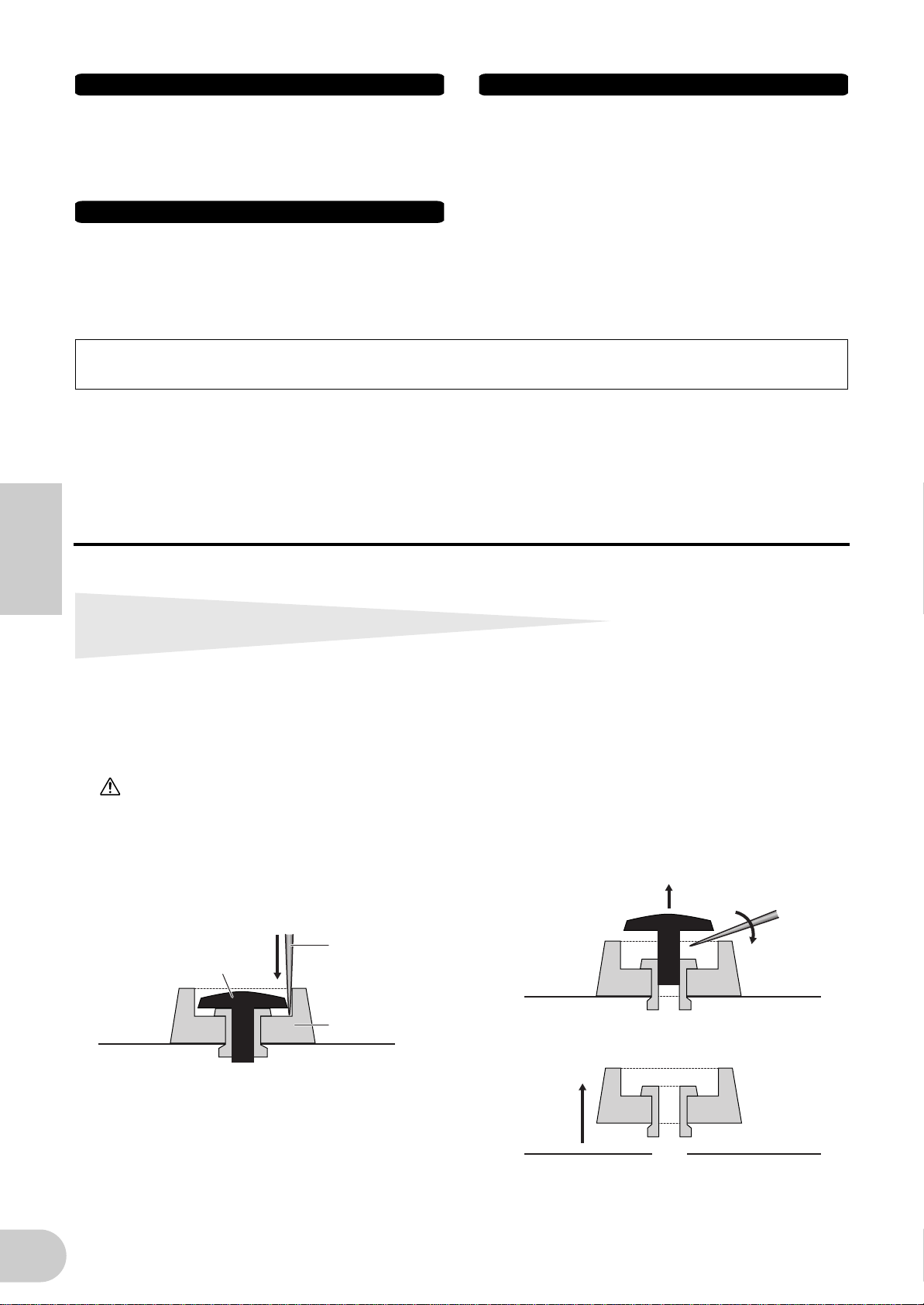
Connexions
Handling caution
• Avant de raccorder l'instrument à d'autres éléments électroniques, mettez ces
derniers hors tension. Et avant de mettre sous/hors tension tous les éléments,
veillez à toujours ramener le volume au minimum. En outre, veillez à régler le
volume de tous les composants au minimum et à augmenter progressivement
le volume sonore des instruments pour définir le niveau d'écoute désiré.
Entretien
• Utilisez un linge doux et sec pour le nettoyage de l'instrument. N’utilisez
jamais de diluants de peinture, solvants, produits d'entretien ou tampons de
nettoyage imprégnés de produits chimiques.
Yamaha n'est pas responsable des détériorations causées par une utilisation impropre de l'instrument ou par des modifications apportées par l'utilisateur, pas plus
qu'il ne peut couvrir les données perdues ou détruites
Veillez à toujours laisser l'appareil hors tension lorsqu'il est inutilisé.
Même lorsque le commutateur est en position « STANDBY », une faible quantité d'électricité circule toujours dans l'instrument. Lorsque vous n'utilisez pas l'instrument
pendant une longue période, veillez à débrancher l'adaptateur secteur de la prise murale.
.
• Ne pas glisser les doigts ou la main dans les fentes de l'instrument.
• N’insérez pas d'objets en papier, métalliques ou autres dans les fentes du
panneau. Si c'est le cas, mettez immédiatement l'appareil hors tension et
débranchez le cordon d'alimentation de la prise secteur. Faites ensuite contrôler
l'appareil par une personne qualifiée du service Yamaha.
• Ne déposez pas d'objets de plastique, de vinyle ou de caoutchouc sur
l'instrument, ce qui risque de décolorer le panneau ou le clavier.
• Ne vous appuyez pas sur l'instrument et n’y déposez pas des objets lourds. Ne
manipulez pas trop brutalement les boutons, commutateurs et connecteurs.
• Ne jouez pas trop longtemps sur l'instrument à des volumes trop élevés, ce
qui risque d'endommager durablement l'ouïe. Si vous constatez une baisse de
l'acuité auditive ou des sifflements d'oreille, consultez un médecin sans
tarder.
(3)-7 2/2
Français
l'installation du montage en rack
La carte i88X est équipée de quatre arrêts amovibles en caoutchouc. Si l'i88X ne rentre pas dans le coffret monté en rack du fait que les arrêts heurtent un autre périphérique, retirez les arrêts comme indiqué ci-dessous.
Avant de retirer les arrêts, vérifiez que vous disposez d'un outil mince et coupant, comme par exemple
une épingle de sûreté ou un trombone déplié.
ATTENTION
N'utilisez pas d'outil qui se détende ou plie facilement, tel qu'un cure-dent ou un fil fin.
Retrait des arrêts en caoutchouc pour
1. Retournez l'i88X à l'envers.
2. Insérez l'outil entre l'arrêt en caoutchouc et
le rivet en plastic (comme indiqué).
Outil
Rivet
coupant
Arrêt en
caoutchouc
3. Tirez le rivet vers le haut pour le dégager
du panneau.
4. Dégagez le arrêts en caoutchouc.
4
Pour fixer à nouveau les arrêts retirés, inversez la
procédure ci-dessus, en insérant les rivets perpendiculairement.
Page 53

Introduction
Merci d'avoir acheté l'interface Yamaha i88X Audio/MIDI.
La connexion de l'interface i88X à un ordinateur permet de développer les environnements de
production musicale qui utilisent un séquenceur audio sur l'ordinateur.
L'interface i88X prend en charge mLAN, un réseau numérique dédié à la musique, basé sur le bus
série IEEE1394, un protocole de données de haute performance. L'interface i88X facilite la
construction de réseaux sophistiqués pour les signaux audio et MIDI IEEE1394 car elle dispense
d'une reconfiguration de câblage, opération complexe qui était indispensable dans les systèmes
classiques antérieurs.
Pour bénéficier pleinement des avantages de la fonctionnalité de l'i88X, lisez attentivement ce
manuel, puis conservez-le à portée de main pour vous y référer ultérieurement.
Contenu du carton
• Unité de l'i88X
• CD-ROM « Tools for i88X/mLAN16E » (Outils pour i88X/mLAN16E)
• CD-ROM « Plug-in Effect » (Effet plug-in)
• Câble mLAN (câble IEEE1394) (de 6 à 6 broches)
• Adaptateur secteur : PA-5D
• Mode d'emploi (ce manuel)
• Manuel d'installation de l'application « Tools for i88X/mLAN16E »
• Carte utilisateur (contenant le numéro de série des effets du logiciel plug-in inclus)
Français
A propos du CD-ROM fourni
L'interface i88X est livrée avec un CD-ROM contenant des logiciels qu'il est judicieux d'utiliser
conjointement à l'i88X. Ces logiciels comportent des pilotes nécessaires à la connexion de l'i88X
à un ordinateur. Ils comprennent également des applications permettant d'assurer
l'acheminement des signaux audio et MIDI entre les périphériques mLAN et les effets plug-in.
Pour plus d'informations, reportez-vous au manuel d'installation de « Tools for i88X/mLAN16E »,
fourni séparément et des manuels d'aide en ligne des applications concernées.
Yamaha n'est pas responsable des détériorations causées par une utilisation impropre du
périphérique ou par des modifications apportées par l'utilisateur, pas plus qu'il ne peut
couvrir les données perdues ou détruites.
• Les illustrations et les écrans d'afficheurs à cristaux liquides figurant dans ce mode d'emploi
servent uniquement à expliciter les instructions et peuvent différer légèrement de ceux
apparaissant sur votre dispositif.
• MIDI est une marque déposée de l'Association of Musical Electronics Industry (AMEI).
• « mLAN » est une marque de fabrique de Yamaha Corporation.
• Les noms des sociétés et des produits apparaissant dans ce mode d'emploi sont des marques de
fabrique ou des marques déposées appartenant à leurs propriétaires respectifs.
5
Page 54

Fonctions
■ Transfert rapide de données via mLAN
La connexion de l'interface i88X à un ordinateur et à d'autre périphériques mLAN via les câbles
IEEE1394 (FireWire/i.LINK) permet de transférer les données audio multi-canal et les signaux MIDI
multi-port vers et depuis une station de travail numérique audio DAW (Digital Audio Workstation)
sur l'ordinateur et les périphériques mLAN connectés (à une vitesse de 400 Mbps (mégaoctets par
seconde) [S400]).
■ Un total de 18 E/S de canal audio
• L'interface i88X est dotée de deux entrées MIC/LINE (Micro/Ligne) et de six entrées LINE (Ligne).
Les entrées 1 et 2 disposent de deux préamplificateurs de micro, d'un son transparent, hérités du
DM2000, ainsi que d'une alimentation dérivée, qui acceptent les prises de casque XLR et TRS.
Les entrées 3 à 8 acceptent les prises de casque TRS (pages 8 et 11).
• L'entrée 1 dispose également d'une prise HI-Z (à haute impédance) permettant de connecter les
instruments à haute impédance comme les guitares ou les basses (page 8).
• Les prises Insert I/O (E/S d'insertion) vous permettent de connecter un processeur d'effets
externe (page 11).
• L'interface i88X est également dotée d'un convertisseur de taux d'échantillonnage, qui prend en
charge les fréquences d'échantillonnage de 44,1 kHz à 96 kHz.
• Les ports MIDI IN et OUT (Entrée/sortie MIDI) autorisent la connexion des périphériques MIDI
externes du système mLAN (page 11).
• L'interface i88X peut traiter les données d'entrée et de sortie de 18 canaux lorsqu'elle s'exécute
sur une fréquence d'échantillonnage de 48 kHz ou 44,1 kHz et les données d'entrée et de sortie
de 14 canaux sur une fréquence d'échantillonnage de 96 kHz ou 88,2 kHz.
■ Caractéristiques audio
Français
• Fréquences d'échantillonnage compatibles : 44,1 kHz, 48 kHz, 88,2 kHz, 96 kHz
• Convertisseurs A/N et N/A linéaires de 24 bits, offrant un suréchantillonnage multiplié par 128
(sur une fréquence d'échantillonnage de 48 kHz ou 44,1 kHz) ou par 64 (sur une fréquence
d'échantillonnage de 96 kHz ou 88,2 kHz)
• Réponse de fréquence : 20 Hz – 20 kHz, plage dynamique standard : 110 dB
■ Fonction d'écoute directe
• Permet d'écouter le son enregistré sur la station de travail DAW sans attente (retard de son)
(page 17).
■ Pack intégré comportant des effets plug-in
• Quatre effets plug-in VST/AU, comprenant des effets d'égaliseur, de voix, de mastérisation, etc.
Table des matières
Retrait des arrêts en caoutchouc pour l'installation du montage en rack................................. 4
Introduction ................................................................................................................................ 5
Contenu du carton...................................................................................................................... 5
Fonctions..................................................................................................................................... 6
Principes de base de mLAN ........................................................................................................ 7
Flux opérationnel de la sortie du son ......................................................................................... 7
Noms et fonctions....................................................................................................................... 8
Panneau avant.................................................................................................................... 8
Panneau arrière ................................................................................................................ 11
Mise sous/hors tension de l'interface i88X et des périphériques connectés........................... 12
Connexion de périphériques externes ..................................................................................... 13
Connexion d'instruments de musique et de microphones et réglage du niveau d'entrée ..... 16
Ecoute directe ........................................................................................................................... 17
Exemples de systèmes............................................................................................................... 18
Établissement d'une connexion mLAN..................................................................................... 20
Voyants DEL .............................................................................................................................. 21
Dépistage des pannes............................................................................................................... 22
Spécifications techniques.......................................................................................................... 25
6
Page 55

Principes de base de mLAN
NOTE
mLAN est un réseau numérique conçu pour les systèmes de musique et basé sur le bus série IEEE1394,
un protocole de communications de données de haute performance, qui constitue la référence dans ce
domaine.
Les environnements musicaux ne prenant pas en charge mLAN nécessitent le branchement de dizaines
de câbles pour les périphériques et les équipements divers, notamment des câbles MIDI et audio
permettant d'acheminer les signaux MIDI et audio. Au moindre changement apporté à ces systèmes, il
faut déconnecter et reconnecter physiquement ces câbles entre eux.
Par exemple, l'ajout d'un synthétiseur à un système nécessite l'installation de deux câbles MIDI et deux
ou plusieurs câbles pour l'équipement audio stéréo. Le montage des connexions appropriées requiert des
connaissances spécifiques concernant les entrées, les sorties, réglages stéréo, et l'impédance des
connecteurs.
Plus le système est important, plus les connexions nécessaires à sa mise en place sont complexes et
onéreuses, et plus grande la probabilité d'erreurs et de problèmes. Il faut beaucoup de temps et d'effort
pour enquêter sur ces erreurs et en établir les causes. Vous avez peut-être déjà fait l'expérience,
désagréable, de démêler l'enchevêtrement de câbles formant une toile d'araignée de connexions
inextricables.
mLAN simplifie le câblage, du fait de l'utilisation d'un seul type de câble IEEE1394, ce qui permet de
configurer des systèmes extrêmement sophistiqués. Il n'est pas nécessaire de reconnecter les câbles pour
modifier l'acheminement des signaux MIDI et audio entre les périphériques mLAN.
Flux opérationnel de la sortie du son
1. Installez « Tools for i88X/mLAN16E ».
........... Reportez-vous à la section relative à l'installation du logiciel dans le manuel
d'installation de ce dernier.
2. Connectez l'ordinateur et les périphériques mLAN à l'aide de câbles IEEE1394.
........... Voir page 13.
3. Lancez mLAN Manager (sous Windows uniquement).
........... Reportez-vous à la section relative à la confirmation de l'installation, dans le
manuel d'installation du logiciel.
4. Pour connecter directement un ordinateur à un seul périphérique mLAN, il faut d'abord lancer
mLAN Auto Connector. Pour connecter un ordinateur à plusieurs périphériques mLAN,
démarrer mLAN Graphic Patchbay.
........... Voir page 20
5. Configurez les connexions dans mLAN Auto Connector ou mLAN Graphic Patchbay.
........... Utilisation d'Auto Connector : reportez-vous à la section relative à la connexion de
l'ordinateur et des périphériques mLAN via mLAN, contenue dans le manuel
d'installation.
........... Utilisation de Graphic Patchbay : reportez-vous à la section relative aux réglages
de connexion mLAN, dans le manuel en ligne de Graphic Patchbay.
6. Spécifiez les entrées et sorties audio et MIDI, d'après les instructions fournies dans le guide de
l'utilisateur de votre station de travail DAW. Indiquez également le séquenceur audio et les
périphériques connectés.
Pour les étapes ultérieures, reportez-vous au mode d'emploi du logiciel et des périphériques connectés
concernés.
Dans ce manuel, le terme de connexion mLAN désigne la configuration des acheminements
de signaux audio, MIDI et d'horloge.
Français
7
Page 56

Noms et fonctions
NOTE
Les numéros signalés à gauche des noms (1-5, 7-A, E-K, et M) correspondent à
ceux qui sont indiqués dans le schéma fonctionnel au dos de la couverture.
Panneau avant
1 2 3 4 3 4 5 76 8 9 0 A CB D5
1 Commutateur [PHANTOM +48V]
Ce commutateur fournit une alimentation dérivée
de +48 V aux prises d'entrée INPUT 1 et 2
compatibles XLR/TRS (3). Il est à noter que
l'alimentation dérivée ne sera pas fournie si un
périphérique externe est connecté à l'une des
prises de casque TRS sur le panneau arrière.
Activez ce commutateur lorsque vous voulez
connecter un microphone à condensateur
nécessitant une alimentation externe de +48 V à la
prise INPUT 1 ou 2 (3). Lorsque le commutateur
Français
est activé, son voyant s'allume.
• Veillez à désactiver ce commutateur si
vous devez connecter un périphérique
ne nécessitant pas d'alimentation
externe sur la prise d'entrée XLR
INPUT 1 ou 2. Autrement,
l'alimentation dérivée pourrait être
fournie au périphérique, au risque de
l'endommager.
• Si vous connectez un périphérique
nécessitant une source d'alimentation
externe, il faut d'abord connecter le
périphérique à un connecteur XLR
puis activer l'alimentation dérivée.
• Lorsqu'elle est activée, l'alimentation
dérivée alimente les deux
prisesINPUT 1 et 2.
• L'alimentation dérivée n'alimente pas
les connecteurs de casque TRS.
NOTE
2
Commutateur [(HI-Z)/LINE/MIC]
Ce commutateur vous permet de sélectionner
l'entrée à haute impédance, l'entrée de micro ou
l'entrée ligne pour les prises INPUT 1 et 2
compatibles XLR/TRS (3).
HI-Z : utilisez ce réglage pour la connexion
Si le commutateur [HI-Z/LINE/MIC] (2)
est réglé sur HI-Z, l'alimentation dérivée
n'alimentera pas la prise INPUT 1 (3).
d'un instrument de musique à haute
impédance, comme par exemple une
guitare avec éléments passifs ou une
basse.
LINE : Utilisez ce réglage pour la connexion
d'un instrument de niveau ligne, comme
par exemple un synthétiseur, un clavier
ou un équipement audio.
MIC : Utilisez ce réglage pour connecter un
périphérique de niveau micro.
NOTE
NOTE
3
Prises d'entrée INPUT 1 et 2 compatibles
Sélectionnez HI-Z, LINE ou MIC pour la
prise INPUT 1. Sélectionnez LINE ou
MIC pour la prise INPUT 2.
Lorsque le commutateur [HI-Z/LINE/
MIC] est réglé sur HI-Z, l'alimentation
dérivée n'alimente pas la prise INPUT 1
(3).
XLR/TRS
Ces prises d'entrée symétriques acceptent les
prises de casque TRS (1/4'') et XLR-3-31. Elles
peuvent être utilisées pour les entrées à haute
impédance et les entrées de ligne ou de micro.
Vous pouvez y brancher des instruments de
musique dotés de sorties asymétriques, tels que les
synthétiseurs ou les boîtes à rythme. Le réglage
approprié du commutateur [HI-Z/LINE/MIC] (2)
vous permet de connecter à la prise INPUT 1 des
instruments à haute impédance, des instruments
de sortie de ligne ou des microphones. Le réglage
adéquat du commutateur [LINE/MIC] (2) vous
donne la possibilité de brancher sur la prise INPUT
2 un instrument de sortie de ligne ou un
microphone.
Niveaux d'entrée nominaux :
MIC : –60 dBu à –16 dBu
LINE : –34 dBu à +10 dBu
HI-Z : –56 dBu à –12 dBu
1 (Masse)
Fiche XLR mâle
Prise TRS 1/4"
Anneau (à froid)
3 (à froid)
2 (à chaud)
Pointe (à chaud)
8
Gaine (masse)
Page 57

Voyants [PEAK]
NOTE
NOTE
NOTE
4
Un voyant [PEAK] (Crête) s'allume en rouge si le
signal d'entrée qui a transité par la commande
[GAIN] (5) atteint le niveau de 3 dB en-dessous
du point d'écrêtage. Pour optimiser l'enregistrement, réglez la commande [GAIN] (5) de sorte
que ce voyant scintille brièvement lorsque le
niveau sonore maximum est atteint.
5
Commandes [GAIN]
Ces commandes vous permettent de régler la
sensibilité d'entrée (gain de l'amplificateur
principal) des prises d'entrée INPUT 1, 2, 3, 4, 5/6
et 7/8. (page 16)
Plage de réglage :
Ch 1 & 2 (Can. 1-2)
MIC: –16dBu à –60dBu
LINE: +10dBu à –34dBu
HI-Z: –12dBu à –56dBu
Ch 3–8 (Can. 3-8)
+10 dBu à –20 dBu
6
Voyants MONITOR [1/2 (44k)] - [7/8 (96k)]
Lorsque les canaux de contrôle sont sélectionnés
via les signaux de sortie du commutateur [SELECT]
7
(Sélecteur) (
correspondants s'allument en rouge dans la
section MONITOR (Contrôle).
Lorsque vous maintenez le commutateur [SELECT]
enfoncé pendant plus d'une seconde, le voyant
correspondant à la fréquence d'échantillonnage
actuellement sélectionnée (44k, 48k, 88k ou 96k)
clignote en rouge.
7
Commutateur MONITOR [SELECT]
), les voyants [1/2] - [7/8]
Le voyant [44k] représente une
fréquence d'échantillonnage de 44,1 kHz
et le voyant [88k] une fréquence
d'échantillonnage de 88,2 kHz.
(Sélecteur de contrôle)
Ce commutateur vous permet de sélectionner un
canal de contrôle émettant des signaux à partir
des prises MASTER OUT L et R (Sortie maître G/D)
sur le panneau arrière (page 17). Appuyez
brièvement sur le commutateur (pendant moins
d'une seconde) à plusieurs reprises pour
sélectionner les canaux de contrôle dans la
séquence suivante :
Off (Désactivation) → CH1/2 → CH3/4 → CH5/6 →
CH7/8 → DIGITAL STEREO → Off
Le voyant MONITOR (
canaux sélectionnés s'allume.
Lorsque vous maintenez ce commutateur enfoncé
pour une seconde ou davantage, le voyant de
MONITOR correspondant à la fréquence
d'échantillonnage actuellement sélectionnée
clignote en rouge.
Il est impossible d'acheminer une entrée
de signal de la prise ADAT NORMAL/
DOUBLE vers un canal de contrôle.
La sélection du canal de contrôle est
réinitialisée sur Off (désactivation)
lorsque vous mettez l'i88X hors tension
puis sous tension à nouveau.
8
Commande [MONITOR VOLUME] (Volume
6
) correspondant aux
de contrôle)
Cette commande règle le niveau de volume du
signal du canal de contrôle sélectionné via le
commutateur [SELECT] (7). Le signal de contrôle
est émis à partir des prises OUTPUT/MASTER 1/L et
2/R et de la prise MASTER PHONES (page 17).
9
Prise MASTER PHONES
Cette prise stéréo permet de brancher un casque
d'écoute stéréo. Les signaux produits à partir des
prises OUTPUT/MASTER 1/L et 2/R sont également
émis depuis cette prise.
0 Commande [MASTER VOLUME] (Volume
principal)
Cette commande règle le niveau des signaux
produits à partir des prises OUTPUT/MASTER 1/L
et 2/R.
NOTE
A
Commutateur [OPTICAL SELECT]
Ce commutateur vous permet de sélectionner la
fonction des prises OPTICAL IN et OUT (Entrée/
sortie optiques) sur le panneau arrière. Pour plus
d'informations, reportez-vous à la section « A
propos du commutateur OPTICAL SELECT, du
voyant MASTER CLOCK et de l'horloge maître » en
page 10.
ADAT DOUBLE :
sélectionnez cette option pour les taux
d'échantillonnage élevés (88,2 kHz ou 96 kHz).
Les prises OPTICAL IN et OUT fonctionnent
comme les prises ADAT IN et OUT (Entrée/
sortie ADAT) qui reçoivent et transmettent des
signaux audio numériques d'un total de quatre
canaux en même temps. Un seul câble optique
combine des signaux audio numériques de
huit canaux, d'une fréquence de 44,1 kHz ou
48 kHz en signaux audio numériques sur
quatre canaux, émettant sur une fréquence de
88,2 kHz ou 96 kHz.
ADAT NORMAL :
sélectionnez cette option pour un taux
d'échantillonnage normal (44,1 kHz ou
48 kHz). Les prises OPTICAL IN et OUT
fonctionnent comme les prises ADAT IN et
OUT qui reçoivent et transmettent des
données audio numériques d'un total de huit
canaux. Ceci est le format standard du
paramètre ADAT.
DIGITAL :
les prises OPTICAL IN et OUT fonctionnent
respectivement comme une entrée et une
sortie stéréo numériques.
NOTE
NOTE
B
Voyants MASTER CLOCK (Horloge maître)
Ces voyants s'allument pour indiquer l'horloge sur
laquelle l'interface i88X est enclenchée. Pour plus
d'informations, reportez-vous à la section « A
propos du commutateur OPTICAL SELECT, du
voyant MASTER CLOCK et de l'horloge maître » en
Pour émettre des signaux audio de
niveau en provenance des entrées
mLAN INPUT à partir des prises 1/L et 2/
R (G) sur un niveau de ligne (+4 dBu),
tournez la commande [MASTER
VOLUME] complètement vers la droite.
Les signaux sont émis au même niveau
que ceux produits à partir des prises de
sortie OUT-PUT 3-8.
Si vous sélectionnez DIGITAL, la prise
COAXIAL IN sera désactivée.
Avant de sélectionner ADAT DOUBLE,
assurez-vous que le périphérique
compatible ADAT prend en charge le
mode ADAT DOUBLE.
Français
9
Page 58

page 10. Vous pouvez sélectionner la fréquence
d'échantillonnage à l'aide des applications mLAN
Auto Connector ou mLAN Graphic Patchbay
(page 20).
INT : L'interface i88X utilise l'horloge interne à
44,1 kHz.
ADAT : L'interface i88X utilise le signal ADAT
entrant comme horloge maître.
mLAN : L'interface i88X utilise le signal mLAN
entrant comme horloge maître.
Vert solide : L'interface i88X est
verrouillée sur l'horloge
maître.
Vert clignotant : L'interface i88X n'est pas
enclenchée sur l'horloge
maître.
C
Voyant [mLAN ACTIVE]
Ce voyant s'allume lorsque l'interface i88X est
opérationnelle. Il s'éteint dès qu'une erreur de
fonctionnement se produit sur un périphérique
mLAN. Lorsque vous cliquez sur la touche [ID]
dans mLAN Auto Connector ou mLAN Graphic
Patchbay (page 20) pour identifier le périphérique
mLAN correspondant dans le réseau, le voyant
clignote.
NOTE
D
Interrupteur [STANDBY/ON] (Veille/Marche)
Le voyant s'allume également pour
signaler que le câble mLAN n'est pas
connecté à l'unité.
Cet interrupteur permet de mettre l'unité sous
tension ou hors tension (Standby).
ATTENTION
Veillez à respecter les procédures décrites à la
section « Mise sous/hors tension de l'interface
i88X et des périphériques connectés » page 12
lorsque vous mettez l'interface i88X sous/hors
tension. Même lorsque l'interrupteur est en
position « STANDBY », une très faible quantité de
courant électrique circule toujours dans l'unité.
Lorsque vous n'utilisez pas l'interface i88X
pendant un certain temps, prenez soin de
débrancher l'adaptateur secteur de la prise
murale.
■ A propos du commutateur OPTICAL SELECT, du voyant MASTER CLOCK et de l'horloge
maître
La fonction des prises OPTICAL IN et OUT (J) spécifiée par le commutateur [OPTICAL SELECT] (7), et le
Français
voyant MASTER CLOCK (B) qui s'allume varient selon le périphérique mLAN qui est utilisé comme horloge
maître au sein du réseau mLAN.
1. Si l'horloge maître est un périphérique
mLAN du réseau mLAN qui n'est ni un
ordinateur ni l'interface i88X (autrement
dit, si l'interface i88X utilise le signal mLAN
entrant comme horloge maître) :
Voyants MASTER CLOCK
Le voyant [mLAN] s'allume.
Commutateur [OPTICAL SELECT]
DIGITAL :
les prises OPTICAL IN et OUT fonctionnent
respectivement comme une entrée et une sortie
stéréo numériques.
ADAT NORMAL ou ADAT DOUBLE :
la fréquence d'échantillonnage du réseau mLAN
détermine le mode de fonctionnement
(NORMAL ou DOUBLE). Vous pouvez
sélectionner l'un ou l'autre modes lorsque les
prises OPTICAL IN et OUT sont utilisées comme
entrée et sortie ADAT.
2. Lorsque l'interface i88X renvoie le signal
d'horloge maître ADAT entrant et qu'elle a
été spécifiée comme horloge maître dans le
réseau mLAN (autrement dit, lorsque l'i88X
utilise le signal ADAT comme horloge
maître) :
Voyants MASTER CLOCK
Le voyant [ADAT] s'allume.
Commutateur [OPTICAL SELECT]
DIGITAL :
les prises OPTICAL IN et OUT fonctionnent
respectivement comme entrée et sortie stéréo
numériques, mais la prise d'entrée IN ne peut pas
recevoir le signal d'horloge ADAT. Par
conséquent, l'interface i88X bascule sur son
horloge interne qui s'exécute sur une fréquence
de 44,1 kHz. (Reportez-vous au cas n˚3).
ADAT NORMAL :
les prises OPTICAL IN et OUT fonctionnent en
mode ADAT NORMAL.
ADAT DOUBLE :
les prises OPTICAL IN et OUT fonctionnent en
mode ADAT DOUBLE .
3. Lorsque l'i88X ne reçoit pas l'horloge
appropriée :
Voyants MASTER CLOCK
Le voyant [INT] s'allume et l'interface i88X
renvoie son horloge interne, qui s'exécute sur
une fréquence de 44,1 kHz. Dans le cas n˚1, le
voyant [mLAN] s'allume également. Dans le cas
n˚2, le voyant [ADAT] s'allume également.
Commutateur [OPTICAL SELECT]
DIGITAL :
la prise OPTICAL IN fonctionne comme entrée
stéréo numérique. Dans ce cas, vous pouvez
toujours contrôler les entrées analogiques (sur les
prises INPUT 1-8) et l'entrée stéréo numérique
(sur la prise OPTICAL IN). Par conséquent, vous
pouvez écouter le son à partir de l'instrument de
musique ou du microphone connecté à
l'interface i88X sans lancer l'ordinateur.
ADAT NORMAL ou ADAT DOUBLE :
les signaux ADAT sont indisponibles, bien que
vous ayez toujours la possibilité de contrôler
l'entrée analogique (sur les prises INPUT 1-8).
10
Page 59

Panneau arrière
21
DC IN
M HK GJ IL
E
Prises INSERT I/O 1 et 2 (casque TRS)
Ces connecteurs TRS 1/4" asymétriques sont
utilisés pour les entrées et sorties d'insertion de
canaux. Utilisez un câble divisé pour insérer un
processeur d'effets externe aux entrées INPUT 1 et
2 (3) du panneau avant. INSERT I/O 1 (E/S
d'insertion 1) correspond à INPUT 1 et INSERT I/O
2 à INPUT 2.
Les broches sont configurées comme suit.
Vers l'entrée du processeur externe
Vers INSERT I/O
Gaine
Gaine
Anneau
Pointe
F
Prises INPUT 3-8 (casque TRS)
Il s'agit de connecteurs d'entrée TRS 1/4"
(symétriques). La plage d'entrée nominale s'étend
de -20 dBu à +10 dBu. Vous pouvez aussi y
brancher des synthétiseurs ou des boîtes à rythme
dotées de sorties asymétriques.
G
Prises OUTPUT 1 et 2 / MASTER OUT L et R
(casque TRS)
Ces prises de sortie de casque TRS 1/4"
(symétriques) émettent un signal audio
analogique, qui constitue une combinaison des
canaux d'entrée 1 et 2 mLAN et de la sortie de
contrôle audio via le commutateur [SELECT] (7)
sur le panneau avant. Le niveau de sortie nominal
est de +4 dBu (pages 16 et 17).
H
Prises OUTPUT 3-8 (casque TRS)
Ces prises de sortie de casque TRS 1/4"
(symétriques) émettent des signaux audio
analogiques sur les canaux d'entrée mLAN 3 à 8.
Le niveau nominal de sortie est de +4 dBu.
I
Prises DIGITAL STEREO COAXIAL IN et OUT
Ces prises coaxiales sont des connecteurs à broche
RCA qui autorisent l'entrée et la sortie des signaux
audio numériques au format utilisateur IEC-60958.
Connectez ces prises aux connecteurs d'entrée et
de sortie d'un enregistreur DAT, MD ou autre, à
l'aide de câbles à broche RCA pour données audio
numériques.
Vers la sortie du processeur externe
MIDI
OUT
Pointe
OUTIN IN
DIGITAL
STEREO
OPTICAL
DIGITAL STEREO
COAXIAL
J
K
L
M
F E
876543
876543
INPUT
(BAL)
2/ R 1/ L
Prises OPTICAL IN et OUT
Ces prises optiques permettent l'entrée et la sortie
des signaux audio stéréo numériques ou ADAT.
Utilisez le commutateur [OPTICAL SELECT] (A)
situé sur le panneau avant pour sélectionner les
modes DIGITAL STEREO, ADAT NORMAL, or ADAT
DOUBLE.
NOTE
Les connecteurs coaxiaux et optiques
d'entrée stéréo numérique sont dotés
d'un convertisseur de taux d'échantillonnage intégré (SRC), qui permet la
réception de signaux audio de différentes fréquences d'échantillonnage en
provenance de périphériques connectés.
Ports MIDI IN et OUT
Connectez ici les équipements MIDI. Ces ports
vous permettent de transmettre des messages
MIDI entre un ordinateur ou des périphériques
mLAN d'un réseau mLAN et un instrument MIDI
connecté à l'interface i88X.
Borne DC IN (Entrée alimentation à
courant continu)
Connectez ici l'adaptateur secteur fourni (PA-5D).
AVERTISSEMENT
Prenez soin d'utiliser l'adaptateur fourni.
L'utilisation d'un autre adaptateur que le PA-5D
peut endommager l'interface i88X et risque
même de vous exposer à un danger
d'électrocution. Connectez l'adaptateur à une
prise secteur dont la tension correspond à la
tension spécifiée.
Connecteurs mLAN 1 et 2
Ces connecteurs IEEE1394 à 6 broches vous
permettent de relier l'interface i88X au
périphérique mLAN ou au périphérique
compatible IEEE1394 (FireWire/i.Link). L'opération
est la même, qu'il s'agisse du connecteur mLAN 1
ou mLAN 2. Si le périphérique ciblé dispose d'un
connecteur à 4 broches, utilisez un câble IEEE1394
de 4 à 6 broches, disponible dans le commerce.
Evitez de créer une connexion en boucle (page 23)
lorsque vous connectez des périphériques.
NOTE
Yamaha recommande l'utilisation d'un
câble IEEE1394 d'une longueur
maximale de 4,5 m.
INSERT I/O
21
OUTPUT / MASTER
+4dB(BAL)
Français
11
Page 60

Mise sous/hors tension de l'interface
r
i88X et des périphériques connectés
Préparation
Avant de connecter l'adaptateur secteur, vérifiez
que l'interrupteur [STANDBY/ON] de l'interface
i88X est réglé sur STANDBY.
A
Branchez la prise de l'adaptateur (PA-5D)
sur la borne DC IN du panneau arrière de
l'interface i88X.
B
Branchez le câble secteur sur une prise de
secteur appropriée.
Panneau arrière
MIDI
Prise de secteu
Câble secteur
1
DC IN
Borne
DC IN
OUT
IN
Adaptateur
secteur PA-5D
Français
NOTE
• Prenez soin d'utiliser l'adaptateur fourni.
L'utilisation d'un autre adaptateur que le PA-5D
peut endommager l'interface i88X et risque
même de vous exposer à un danger
d'électrocution.
• Connectez l'adaptateur à une prise secteur dont
la tension correspond à la tension spécifiée.
Même lorsque l'interrupteur [STANDBY/ON] est
en position « STANDBY », une très faible quantité
de courant électrique circule toujours dans l'unité.
Lorsque vous n'utilisez pas l'interface i88X
pendant un certain temps, prenez soin de
débrancher l'adaptateur secteur de la prise
murale.
Séquence de mise sous/hors tension des
Suivez cette procédure dans l'ordre
inverse pour déconnecter l'adaptateur
secteur.
AVERTISSEMENT
ATTENTION
périphériques connectés
2
1. Mettez sous tension les périphériques
externes, comme par exemple une source
de son ou un processeur d'effets reliés aux
connecteurs d'entrée et de sortie de
l'interface i88X.
2 Mettez sous
tension
ALLUMÉ !!
l'interface
i88X.
3 Mettez sous tension
l'équipement audio
externe connecté à la
sortie de l'interface
→
i88X. (mixeur
amplificateur)
NOTE
Une fois que vous avez remis l'interface
i88X sous tension, relancez la station de
travail DAW.
Pour mettre les périphériques hors
tension, diminuez d'abord le niveau du
volume de l'équipement audio, puis
procédez à la mise hors tension des
périphériques, dans l'ordre inverse.
Mettez sous tension l'interface i88X.
ATTENTION
Pour protéger les haut-parleurs, avant de mettre
l'interface i88X sous tension, baissez les
réglages de volume sur l'interface et sur
l'équipement audio connecté.
A
Appuyez sur l'interrupteur
[STANDBY/ON] sur
l'interface i88X pour mettre
l'unité sous tension.
12
Une fois que vous avez connecté l'interface i88X
et les périphériques externes (page 13), vérifiez
que les réglages de volume de l'interface et de
l'équipement audio externe sont au niveau
minimal, puis mettez sous tension les
périphériques dans l'ordre suivant.
NOTE
Installez le pilote mLAN (pour
Windows) alors que l'interface i88x est
encore désactivée. (Reportez-vous au
manuel d'installation fourni
séparément).
B
Augmentez le volume de l'amplificateur en
le réglant sur un niveau approprié.
C
Procédez au réglage
approprié des commandes
[GAIN], [MONITOR
VOLUME] et [MASTER
VOLUME] de l'interface i88X.
Page 61

Connexion de périphériques externes
ATTENTION
Avant de connecter des périphériques externes à l'interface i88X, mettez tous les périphériques hors tension.
Avant de mettre les périphériques sous ou hors tension, il faut diminuer au minimum le réglage de volume sur
tous les périphériques concernés, sous peine de provoquer un choc électrique ou d'endommager les dispositifs.
Le schéma suivant illustre un exemple type de connexion. Reportez-vous à ce schéma pour connecter
des microphones, des instruments de musique, un ordinateur ou d'autres périphériques externes.
Guitare électrique/Basse/
Microphone
Enregistreur CD/Mixeur
compatible ADAT
CasqueMicrophone
Processeur d'effets
88
Français
Ordinateur compatible
IEEE1394
21
Synthétiseur/Générateur de sons
Périphérique mLAN
tel que le 01X
DIGITAL
STEREO
OUTIN IN
OPTICAL
DIGITAL STEREO
COAXIAL
876543
876543
INPUT
(BAL)
21
2/ R 1/ L
VOL
INSERT I/O
OUTPUT / MASTER
+4dB(BAL)
VOL
MIDI
DC IN
OUT
Système d'écoute
Mixeur analogique
13
Page 62

Horloges
NOTE
NOTE
Dans un système constitué de plusieurs dispositifs numériquement connectés, tous les périphériques
numériques doivent être synchronisés lorsque les signaux audio numériques sont transférés d'un
dispositif à l'autre.
Même si les périphériques utilisent les mêmes fréquences d'échantillonnage, si le timing de leurs
traitements audio respectifs n'est pas synchronisé, ils risquent de ne pas recevoir les signaux
correctement, ce qui peut engendrer des bruits parasites, des dissonances et des déclics. La
synchronisation est réalisée à l'aide d'une horloge (un signal d'impulsion d'horloge qui synchronise
tous les signaux audio numériques d'un système).
Dans un sytème audio numérique type, un seul dispositif fonctionne comme l'horloge « maître » et
transmet un signal d'horloge. Les autres dispositifs se comportent comme des horloges « esclaves »,
qui se synchronisent sur l'horloge maître.
Pour connecter une interface i88X aux périphériques externes via mLAN, allez dans mLAN Auto
Connector ou mLAN Graphic Patchbay, spécifiez un périphérique comme maître et les autres comme
esclaves. L'interface i88x peut fonctionner sur une fréquence d'échantillonnage de 44,1 kHz, 48 kHz,
88,2 kHz ou 96 kHz en tant qu'horloge maître ou esclave.
Utilisation de l'interface i88X comme horloge maître dans un réseau mLAN
(Utilisation d'un périphérique compatible ADAT comme horloge maître d'un réseau mLAN)
1. Affectez le périphérique compatible ADAT connecté à l'interface i88X comme maître.
2. Réglez le commutateur [OPTICAL SELECT] situé sur le panneau avant sur ADAT DOUBLE ou
ADAT NORMAL (page 10).
3. Dans mLAN Auto Connector ou mLAN Graphic Patchbay, affectez l'interface i88X comme
horloge maître dans le réseau mLAN.
Utilisation de l'interface i88X comme horloge esclave dans un réseau mLAN
Français
Dans mLAN Auto Connector ou mLAN Graphic Patchbay, affectez un périphérique mLAN autre que
l'ordinateur ou l'interface i88X comme horloge maître.
Pour plus d'informations sur le réglage de la fréquence d'échantillonnage et l'horloge, reportez-vous
au manuel d'installation ou au manuel en ligne de mLAN Graphic Patchbay ou bien encore au mode
d'emploi de votre périphérique compatible ADAT.
Enregistrement des réglages de connexion mLAN sur le périphérique mLAN
correspondant
Lorsque vous effectuez des connexions mLAN sur l'ordinateur, les réglages de connexion sont
automatiquement enregistrés sur les périphériques mLAN correspondants. Ainsi, si vous avez utilisé
mLAN Graphic Patchbay pour configurer un réseau qui exclut un ordinateur, la prochaine fois que
vous utilisez le réseau, vous pouvez l'activer en mettant simplement sous tension les périphériques
mLAN du réseau (sans démarrer l'ordinateur).
Pour définir le périphérique comme horloge esclave, utilisez un périphérique numérique ou
un périphérique compatible ADAT (si connecté au i88X).
Pour les détails sur la configuration système et les réglages requis pour les connexions
mLAN, reportez-vous au manuel d'installation fourni séparément ou au manuel en ligne de
mLAN Graphic Patchbay.
14
Page 63

Connexion de périphériques externes dans le cadre de l'utilisation de l'interface i88X
NOTE
NOTE
NOTE
NOTE
avec un ordinateur
Lorsque vous utilisez simultanément des périphériques audio, des instruments de musique et des
ordinateurs, le système risque de produire des bruits, dont l'importance varie en fonction des
connexions. Par conséquent, il est très important de savoir comment atténuer ces bruits lors de la
conception et de la configuration d'un studio.
Malgré le degré de perfectionnement de l'interface i88X, celle-ci est aussi susceptible de générer des
bruits. Différents types de bruit peuvent être produits et enregistrés sur votre séquenceur audio, en
fonction des sources d'alimentation et du schéma de mise à la terre, ainsi que des différents
périphériques connectés.
Il n'existe pas de solution idéale pour éliminer totalement ces bruits. Vous pouvez toutefois les réduire en
isolant leur cause et en leur choisissant un remède approprié. En voici quelques exemples.
• Bourdonnement ou bruissement aigu au niveau de l'ordinateur
Ce bourdonnement est provoqué par le bruit de fonctionnement de l'ordinateur, lorsqu'il atteint
d'autres périphériques via le câble mLAN ou audio. Il peut avoir pour origine une mise à la terre
incorrecte de la source d'alimentation.
• Bourdonnement bas
Les bruits de ce type sont généralement dus à une mise à la terre incorrecte de la source
d'alimentation.
Les bruits peuvent varier selon les circonstances (caractéristiques techniques des
périphériques et environnements d'utilisation).
Si vous êtes confronté à des problèmes de ce type, essayez les solutions suivantes afin d'atténuer les
bruits.
Si le bruit disparaît lorsque vous baissez le volume de l'interface i88X et/ou s'il persiste même
après avoir débranché le câble mLAN ou mis l'ordinateur hors tension, il est probable que ces
bruits ont une toute autre origine. Reportez-vous à la section « Dépistage des pannes » du
mode d'emploi.
1. Utilisez des connexions de câble symétriques lorsque vous connectez un périphérique audio
analogique.
L'utilisation de connexions symétriques appropriées vous permet d'atténuer les bruits.
Il est possible que cette mesure soit sans effet, en fonction des caractéristiques techniques
du périphérique connecté.
Français
■ Câbles recommandés
Entrées de l'i88X
Sorties des périphériques connectés / Entrées de l'i88X (symétriques)
Symétriques
(mixeur, préamplificateur de
micro, etc.)
Asymétrique
(Générateur de sons MIDI,
etc.)
Casque TRS 1/4" / XLR ↔ Câble symétrique de casque TRS/XLR Can. 1-2
Casque TRS 1/4" / XLR ↔ Câble symétrique de casque TRS Can. 3-8
Casque 1/4" asymétrique ↔ Câble symétrique de casque TRS/XLR Can. 1-2
Casque 1/4" asymétrique ↔ Câble symétrique de casque TRS Can. 3-8
Entrées
de l'i88X
Sorties de l'i88X
Sorties de l'i88X (OUTPUT1-OUTPUT8) / Entrées des périphériques connectés
(symétriques)
Symétriques Casque TRS 1/4" symétrique ↔ Câble symétrique TRS / XLR —
—
2. Insérez un boîtier d'adaptation conventionnel (passif, avec transformateur et commutateur à la
terre) afin de brancher le câble audio (analogique).
Vous pouvez utiliser plusieurs boîtiers d'adaptation en cas de connexion de périphériques
multiples.
Exemple : OUTPUT 1/2 de l'i88X – [boîtier d'adaptation] – haut-parleur
Synthétiseur – [boîtier d'adaptation] – i88X
3. Modifiez la source d'alimentation des différents périphériques.
AVERTISSEMENT
Cette solution est extrêmement dangereuse et peut provoquer une décharge électrique. Il convient dès lors de
faire appel à des personnes qualifiées et expérimentées. Veuillez contacter votre représentant Yamaha le plus
proche ou un revendeur agréé (reportez-vous à la dernière page du mode d'emploi).
15
Page 64

Connexion d'instruments de musique et de
NOTE
NOTE
microphones et réglage du niveau d'entrée
Les signaux entrant sur les prises INPUT 1-8 sont acheminés respectivement vers les canaux 1-8 de sortie
mLAN. Si vous avez sélectionné parmi les canaux 1/2 jusqu'à 7/8 une paire de canaux pour la sortie de
contrôle, vous pouvez contrôler les signaux d'entrée correspondants à partir des prises MASTER L et R et
MASTER PHONES (page 17).
Cette section décrit la connexion des instruments de musique et des microphones aux prises INPUT 1-8
et le réglage du niveau des signaux d'entrée.
mLAN
OUTPUTS
(Vers la sortie DAW)
ANALOG
INPUTS
1, 2, 3/4,
5/6, 7/8
Français
1. Tournez les commandes [MASTER VOLUME] et [MONITOR VOLUME] jusqu'au bout et réglez-les
GAIN
MONITOR
SELECT
INSERT I/O
(Can. 1 et 2 uniquement)
mLAN INPUTS
3-8
(provenant de la sortie DAW)
mLAN INPUTS
1, 2
(provenant de la sortie maître DAW)
MONITOR
VOLUME
MASTER
VOLUME
ANALOG
OUTPUTS
3-8
CASQUE
ANALOG
OUTPUTS
1/L, 2/R
sur le niveau minimum (faites-les pivoter dans le sens contraire des aiguilles d'une montre
jusqu'à ce que le bouton de la commande ne tourne plus).
Pour connecter les périphériques sur INPUT 1 et 2, réglez le commutateur [(HI-Z)/LINE/MIC]
sur un réglage approprié pour les périphériques connectés (page 8).
Vous pouvez insérer un processeur d'effets via les prises INSERT I/O dans les canaux
d'entrée analogiques 1 et 2 (INPUT 1 et 2).
2. Connectez les instruments de musique et les microphones sur les prises INPUT 1-8.
3. Réglez la commande [GAIN] pour les prises INPUT sur lesquelles vous avez connecté les
instruments de musique et les microphones.
4. Réglez les commandes [MASTER VOLUME] et [MONITOR VOLUME].
Prises d'entrée INPUT 1 et 2 :
Pour enregistrer au niveau optimal, réglez les commandes [GAIN] de sorte que le voyant [PEAK] de
chaque entrée scintille brièvement lorsque le niveau sonore maximum est atteint.
Prises d'entrée INPUT 3 -8 :
Surveillez les indicateurs de niveau de votre station de travail DAW ou du séquenceur audio lorsque vous
réglez les commandes [GAIN] afin d'augmenter le niveau jusqu'au point précédant immédiatement
l'écrêtage du signal.
16
Page 65

Ecoute directe
NOTE
Vous pouvez contrôler directement les signaux d'entrée aux prises INPUT 1-8, COAXIAL ou OPTICAL
DIGITAL STEREO INPUT via les prises MASTER L et R et MASTER PHONES.
Lorsqu'un signal audio entrant, tel qu'un signal de guitare ou de voix est émis via l'ordinateur, il peut y
avoir un certain temps d'attente. Cependant, la fonction d'écoute directe vous permet de contrôler le
signal avant qu'il ne soit émis sur l'ordinateur connecté, de sorte à éviter un temps d'attente au niveau du
signal d'écoute.
Si vous souhaitez enregistrer sur la station de travail DAW votre performance vocale ou
musicale accompagnant le pistes d'accompagnement de la station DAW, tout en écoutant le
son par le biais de l'i88W, désactivez la fonction d'écoute sur la station DAW. Autrement, vous
serez obligé d'écouter simultanément le son retardé provenant de la station DAW et le son
non retardé contrôlé par l'i88X, ce qui produirait un brouillage sonore.
mLAN INPUTS
1, 2
ANALOG
INPUTS
DIGITAL STEREO
INPUTS
1/2
3/4
5/6
7/8
MONITOR
SELECT
MONITOR
VOLUME
MASTER
VOLUME
CASQUE
ANALOG
OUTPUTS
1/L, 2/R
1. Suivez les étapes 1 et 2 décrites dans la section « Connexion d'instruments de musique et de
microphones et réglage du niveau d'entrée » page 16 pour connecter les instruments de
musique et les microphones aux prises INPUT 1-8, COAXIAL ou OPTICAL DIGITAL SETEREO
INPUT.
2. Appuyez plusieurs fois sur la touche [SELECT] du panneau avant (page 9) afin de sélectionner
un canal d'entrée pour l'écoute directe du son sur les prises MASTER OUT L et R du panneau
arrière.
Appuyez brièvement sur le commutateur (pendant moins d'une seconde), à plusieurs reprises, pour
sélectionner les canaux de contrôle dans la séquence suivante :
→
Off (Désactivation)
CH1/2 → CH3/4 → CH5/6 → CH7/8 → DIGITAL STEREO -> Off
Le voyant MONITOR (page 9) correspondant aux canaux sélectionnés s'allume.
3. Réglez les commandes [GAIN] pour les canaux INPUT (sur lesquels les instruments de musique
et les microphones sont connectés) ainsi que la commande [MASTER VOLUME].
4. Réglez la commande [MONITOR VOLUME].
Les signaux d'écoute sont émis sur les prises MASTER L et R et sur la prise MASTER PHONES.
La commande [MONITOR VOLUME] vous permet de régler le volume des signaux d'écoute sans
modifier le niveau d'enregistrement (gain d'entrée).
Français
17
Page 66

Exemples de systèmes
1. Connexion de l'interface i88X à l'ordinateur
Branchez le connecteur IEEE1394 d'un ordinateur compatible IEEE1394 sur le connecteur mLAN de
l'interface i88X à l'aide d'un câble IEEE1394. Allez dans mLAN Auto Connector ou mLAN Graphic
Patchbay (page 20) et acheminez les signaux audio et MIDI entre l'ordinateur et l'i88X, puis réglez
l'horloge.
Ce système vous permet de transférer simultanément des suites de données audio multiples à partir
des instruments de musique et du mixeur connectés vers l'ordinateur, et de transférer simultanément
des sorties audio multiples de l'ordinateur vers le mixeur.
Français
Guitare/
Basse
Connexion d'instruments de musique
et d'un microphone Connexion d'une console de mixage
Ordinateur compatible IEEE1394 Ordinateur compatible IEEE1394
Câble IEEE1394
i88X i88X
Microphone
MTR
Câble IEEE1394
PAD
26dB
26dB226dB326dB426dB526dB626dB726dB826dB926dB1026dB1126dB
–60–16
–60–16
–60–16
+10 –34
+10 –34
+10 –34
+10 –34
GAIN
GAIN
GAIN
1
UTILITY MIDI SETUP VIEW
PAN/
DYNAMICS EQ/ATT Ø/DELAY
ROUTING
FADER MODE
EFFECT 1 EFFECT 2 OPTION I/O REMOTE
AUX 1
AUX 2 AUX 3 AUX 4
HOME
4
3
2
1
17
SEL
SEL
SEL
SEL
SOLO
SOLO
SOLO
SOLO
ON
ON
ON
ON
6
6
6
6
0
0
0
0
5
5
5
5
10
10
10
10
20
20
20
20
40
40
40
40
60
60
60
60
∞
∞
∞
∞
4
3
2
1
17
18 19 20 21 22 23 24
OFF
OFF
ON
ON
PHANTOM +48V
PHANTOM +48V
INPUT (BAL)
131415
16
15/16
–60–16
–60–16
–60–16
+10 –34
+10 –34
GAIN
GAIN
GAIN
FUNCTION
MEMORY
1 RETURN 2
7
6
5
232221201918
SEL
SEL
SEL
SOLO
SOLO
SOLO
ON
ON
ON
6
6
6
0
0
0
5
5
5
10
10
10
20
20
20
40
40
40
60
60
60
∞
∞
∞
7
6
5
2TR IN
–60–16
–60–16
–60–16
–60–16
–60–16
–60–16 –20+10 100 100
–20+10
GAIN
+10 –34
+10 –34
+10 –34
+10 –34
+10 –34
+10 –34
GAIN
GAIN
GAIN
GAIN
GAIN
GAIN
12
13/14 15/16 PHONES
DIGITAL MIXING CONSOLE
EQ
HIGH
PAN
PAN
HI-MID
F
F
G
LO-MID
G
LOW
SELECTED CHANNEL
STEREO
15/16
13/14
12
11
10
9
8
1 RETURN 2
24
MASTER
SEL
SEL
SEL
SEL
SEL
SEL
SEL
SELSEL
SOLO SOLO
SOLO
SOLO
SOLO
SOLO
SOLO
SOLO
SOLO
ON
ON ON
ON
ON
ON
ON
ON
ON
ON
–1/DEC
0
6
6
6
6
6
6
6
–5
0
0
0
0
0
0
0
–10
–15
5
5
5
5
5
5
5
–20
10
10
10
10
10
10
10
–30
–40
20
20
20
20
20
20
20
–50
40
40
40
40
40
40
40
–70
60
60
60
60
60
60
60
– ∞
∞
∞
∞
∞
∞
∞
∞
ENTER
STEREO
15/16
13/14
12
11
10
9
8
MASTER
–10dBV (UNBAL)
L
R
OUT
IN
2TR
PHONES
MONITOR
2TR IN
LEVEL LEVELGAIN
MONITOR
OUT
L STEREO R
CLIP
–3
–6
–9
–12
–15
–18
–24
–30
–36
–42
–48
SEL
SOLO
MEMORY
+1/INC
PARAMETER
CURSOR
18
Synthétiseur
Ordinateur
mLAN MIDI
IN/OUT
mLAN IN/OUT
1-8ch
mLAN IN/OUT
9-10ch
mLAN IN/OUT
MIDI
IN/OUT
INPUT/
OUTPUT
1-8
DIGITAL
STEREO
IN/OUT
2. Utilisation de plusieurs périphériques mLAN
mLAN
IN/OUT
ADAT
IN/OUT
Mixeur
11-18ch
(44,1kHz/48kHz)
11-14ch
(88,2kHz/96kHz)
MONITOR
SELECT
MASTER OUT
L/R
Page 67

Branchez le connecteur mLAN (IEEE1394) d'un ordinateur compatible IEEE1394 et le connecteur
NOTE
mLAN (IEEE1394) du 01X Digital Mixing Studio et de l'interface i88X à l'aide de câbles IEEE1394.
Dans mLAN Graphic Patchbay (reportez-vous au manuel en ligne de mLAN Graphic Patchbay),
acheminez les signaux audio et MIDI entre l'ordinateur et l'interface i88X, puis réglez l'horloge.
Ce système vous permet d'exploiter au mieux la fonction 01X Digital Mixing (mixage numérique d'un
total de 28 canaux). Utilisez huit entrées A/N sur le 01X et huit entrées A/N sur l'i88X pour transférer
les données audio analogiques de 16 canaux vers le 01X. L'interface i88X dispose de huit sorties N/A
et le 01X d'une sortie MONITOR OUT (stéréo) et d'une sortie STEREO/AUX OUT (stéréo). Ces
interfaces analogique et les prises COAXIAL et OPTICAL DIGITAL STEREO de l'i88X développent les
entrées et sorties analogiques et numériques sur le 01X.
Le nombre de canaux d'entrée et de sortie disponibles varie selon les périphériques mLAN
connectés. Pour une performance optimale, il est recommandé de se connecter à quatre
périphériques mLAN (dont un ordinateur) dans un même réseau. Si le réseau comporte un
périphérique mLAN qui n'est compatible qu'avec un faible taux de transfert (200 Mbps (S200)),
le nombre de périphériques et de canaux disponibles pour les connexions sera réduit.
Ordinateur compatible
IEEE1394
Enregistreur ADAT
Echantillonneur
Microphones
01X
Guitare
ADAT
Câble IEEE1394
Français
i88X
Synthétiseur
Basse
MTR
Ordinateur
01X i88X
mLAN OUT
1-16ch
MIXEUR
mLAN IN
1-18ch
INPUT
1-8
mLAN
IN/OUT
mLAN
IN/OUT
mLAN
IN/OUT
1-8ch
INPUT/
OUTPUT
1-8
mLAN
IN/OUT
9-10ch
DIGITAL
STEREO
IN/OUT
mLAN IN/OUT
11-18ch
(44,1kHz/48kHz)
11-14ch
(88,2kHz/96kHz)
ADAT
IN/OUT
19
Page 68

Établissement d'une connexion mLAN
NOTE
Dans un système mLAN, vous pouvez facilement configurer et maintenir le système, brancher ou
débrancher les connecteurs mLAN sur l'ordinateur et sur chaque périphérique mLAN (connecteurs
virtuels d'entrée et de sortie de données audio/MIDI) et effectuer divers réglages de connexion mLAN
(comme par exemple la synchronisation) en utilisant les applications logicielles mLAN Graphic Patchbay
et mLAN Auto Connector. Il n'est pas nécessaire de re-connecter les câbles audio et MIDI pour s'adapter
aux différents environnements de production musicale.
mLAN Auto Connector
Cette application vous permet de connecter l'ordinateur à un seul périphérique mLAN.
Elle facilite la sélection de l'horloge et des canaux d'entrée et de sortie audio.
Pour les informations sur l'installation et l'utilisation des logiciels, reportez-vous au manuel
d'installation fourni séparément.
Vous pouvez également utiliser mLAN Graphic Patchbay pour connecter l'ordinateur à un
seul périphérique mLAN.
Windows Macintosh
Français
mLAN Graphic Patchbay
Cette application graphique vous permet de gérer les réglages de connexions mLAN pour l'ordinateur
et les périphériques mLAN connectés. Vous pouvez avoir une vue d'ensemble instantanée de toutes
les connexions en visualisant les graphiques de configuration du système mLAN. Vous avez également
la possibilité de modifier de façon intuitive les réglages d'horloge et l'acheminement des signaux
audio et MIDI, comme si vous connectiez des câbles physiques.
Pour les informations sur l'installation et l'utilisation des logiciels, reportez-vous au manuel
d'installation fourni séparément et au manuel en ligne de mLAN Graphic Patchbay.
Windows Macintosh
20
Page 69
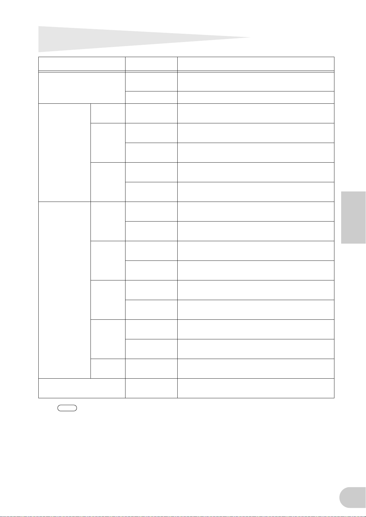
Voyants DEL
NOTE
Voyants Etat Signification
ACTIVE Bleu fixe L'interface i88X fonctionne normalement comme un
périphérique mLAN.
Désactivé Une erreur s'est produite lors de l'opération mLAN.
MASTER CLOCK INT Vert fixe L'interface i88X utilise la fréquence d'échantillonnage
INTERNAL de 44,1 kHz.
ADAT Vert fixe L'interface i88X est enclenchée sur l'horloge maître
(ADAT).
Vert clignotant L'interface i88X n'est pas enclenchée sur l'horloge
maître (ADAT).
mLAN Vert fixe L'interface i88X est enclenchée sur l'horloge maître
(ADAT).
Vert clignotant L'interface i88X n'est pas enclenchée sur l'horloge
maître (ADAT).
MONITOR
/Sampling Rate
PEAK Rouge fixe Le signal d'entrée analogique a atteint son niveau de
1/2 (44k) Rouge fixe CAN. 1 et 2 sont sélectionnés pour le contrôle de
sortie.
Rouge
clignotant
3/4 (48k) Rouge fixe CAN. 3 et 4 sont sélectionnés pour le contrôle de
Rouge
clignotant
5/6 (88k) Rouge fixe CAN. 5 et 6 sont sélectionnés pour le contrôle de
Rouge
clignotant
7/8 (96k) Rouge fixe CAN. 7 et 8 sont sélectionnés pour le contrôle de
Rouge
clignotant
DIGITAL Rouge fixe La prise DIGITAL est sélectionnée pour la sortie de
L'interface i88X utilise une fréquence d'échantillonnage
de 44,1 kHz.
sortie.
L'interface i88X utilise une fréquence d'échantillonnage
de 48 kHz.
sortie.
L'interface i88X utilise une fréquence d'échantillonnage
de 88 kHz.
sortie.
L'interface i88X utilise une fréquence d'échantillonnage
de 96 kHz.
contrôle.
crête.
Français
Lorsque vous maintenez le commutateur [SELECT] enfoncé pendant plus d'une seconde, le
voyant MONITOR/Sampling Rate correspondant à la fréquence d'échantillonnage
actuellement sélectionnée (44k, 48k, 88k ou 96k) clignote en rouge.
21
Page 70

Si vous rencontrez un problème…
Si vous n'entendez aucun son ou entendez un son étrange, vérifiez d'abord les éléments décrits cidessous et prenez les mesures qui s'imposent. Si le problème persiste, consultez votre revendeur Yamaha.
■
Français
■
■
22
Dépistage des pannes
Aucun son ou un son de très faible volume
• Avez-vous correctement branché les enceintes ou le casque ?
• Avez-vous mis l'ampli et les éventuels périphériques externes sous tension ?
• Le signal du périphérique externe est-il bien reçu ?
• Le câble de connexion avec le périphérique externe peut être défectueux.
• Les réglage d'horloge pour l'i88X et le(s) périphérique(s) externe(s) sont-ils corrects ?
.............Reportez-vous à la section relative à la connexion d'un ordinateur à un périphérique mLAN
via mLAN, contenue dans le manuel d'installation, ainsi qu'à la section concernant les
réglages d'horloge dans le manuel en ligne de mLAN Graphic Patchbay.
• Tous les réglages de niveau (des générateurs de sons, des périphériques de reproduction et de l'application elle-
même) sont-ils appropriés ?
• (Pour Windows) Le pilote mLAN (mLAN Driver) est-il paramétré sur « ON » ? Dans la barre de tâches, cliquez
avec le bouton droit sur mLAN Manager (icône mLAN).
• Les autres réglages mLAn sont-ils appropriés ?
.............Reportez-vous à la section « Impossible de communiquer via mLAN » (page 23).
• S'il y a plus de quatre périphériques sur le réseau (dont un ordinateur), la limite de la largeur de bande du bus
IEEE1394 peut avoir été dépassée.
• La limite de la largeur de bande du bus IEEE1394 peut avoir été dépassée. Vérifiez la largeur de bande actuelle à
l'aide de mLAN Graphic Patchbay, et déconnectez certains périphériques si nécessaire.
............. Reportez-vous à la section concernant la barre de menus dans le manuel en ligne de mLAN
Graphic Patchbay.
• S'il y a un périphérique mLAN prenant uniquement en charge S200 sur le réseau mLAN, la largeur de bande du
bus IEEE1394 peut être réduite et sa limite dépassée. Réduisez le nombre de périphériques mLAN connectés au
réseau ou déconnectez certains dispositifs si nécessaire.
.............Reportez-vous à la section concernant la barre de menus dans le manuel en ligne de mLAN
Graphic Patchbay.
Le son est distordu
• La commande [GAIN] est-elle réglée correctement ?
.............Reportez-vous à la page 16.
• Le câble de connexion avec le périphérique externe peut être défectueux.
• Les réglage d'horloge pour l'i88X et le(s) dispositif(s) externe(s) sont-ils corrects ?
.............Reportez-vous à la section relative à la connexion d'un ordinateur à un périphérique mLAN
via mLAN, contenue dans le manuel d'installation, ainsi qu'à la section concernant les
réglages d'horloge dans le manuel en ligne de mLAN Graphic Patchbay.
• Vérifiez que les données audio sont enregistrées au niveau approprié.
Un bruit est audible
• Le réglage de temps d'attente du pilote mLAN est-il approprié ?
.............Reportez-vous aux sections relatives à la configuration du driver mLAN et au panneau de
commandes de ASIO mLAN, dans le manuel d'installation.
• (Pour Windows) La désactivation (Off) de la fonction Hyper Threading dans les paramètres du BIOS peut
résoudre le problème.
• Les réglage d'horloge pour l'i88X et le(s) périphérique(s) externe(s) sont-ils corrects ?
.............Reportez-vous à la section relative à la connexion d'un ordinateur à un périphérique mLAN
via mLAN, contenue dans le manuel d'installation, ainsi qu'à la section concernant les
réglages d'horloge dans le manuel en ligne de mLAN Graphic Patchbay.
• Si le disque dur de votre ordinateur est lent, des problèmes risquent de survenir en cours d'enregistrement et de
reproduction.
• Si vous connectez/déconnectez le LAN, l'USB ou les câbles aux bornes des mini prises du Macintosh tandis que
vous utilisez le mLAN, des bruits parasites risquent d'être produits et/ou les données coupées. Prenez soin de ne
pas brancher ou débrancher de connexion lorsque vous utilisez le mLAN.
• Le nombre de canaux audio est-il approprié ? Le nombre de canaux audio pouvant être utilisés simultanément
varie selon la capacité et la vitesse de l'ordinateur.
.............Reportez-vous à la section relative à la connexion d'un ordinateur à un périphérique mLAN
via mLAN, contenue dans le manuel d'installation, ainsi qu'à la section concernant les
réglages de connexion mLAN dans le manuel en ligne de mLAN Graphic Patchbay.
• La vitesse d'échantillonnage (horloge) est-elle correcte ? Un taux d'échantillonnage élevé peut être à l'origine de
la production de bruits, cela dépend de la capacité et de la vitesse de l'ordinateur.
.............Reportez-vous à la section relative à la connexion d'un ordinateur à un périphérique mLAN
via mLAN, contenue dans le manuel d'installation, ainsi qu'à la section concernant les
réglages de connexion mLAN dans le manuel en ligne de mLAN Graphic Patchbay.
• Vérifiez que l'ordinateur est connecté au nombre approprié de périphériques. La connexion d'un trop grand
nombre de périphériques risque de générer du bruit, selon la capacité de l'ordinateur utilisé.
Page 71

• Des périphériques produisant des parasites (tels que des périphériques contenant des inverseurs d'alimentation,
Ordinateur
Computer
i88X
i88X
: Ordinateur compatible IEEE 1394
etc.) sont-ils situés à proximité des câbles? Eloignez tous les câbles des sources possibles de parasites.
• Vérifiez que le câble mLAN n'est pas défectueux. Les câbles qui ne répondent pas aux normes IEEE1394 risquent
de générer du bruit.
• Ne lancez pas d'autres applications en arrière-plan, comme par exemple un anti-virus. Lorsque vous utilisez le
système mLAN, désactivez les autres applications qui s'exécutent en arrière-plan. Si ces applications demeurent
ouvertes, le fonctionnement du pilote peut devenir instable ou provoquer du bruit. Si vous n'avez pas l'intention
d'utiliser le système mLAN, vous pouvez activer ces applications. (Vous pouvez activer et désactiver le pilote
mLAN à l'aide de mLAN Manager).
■
Nombre insuffisant de pistes pour l'enregistrement ou la reproduction
• Le nombre de canaux de réception/transmission audio de mLAN (réglés dans mLAN Auto Connector et mLAN
Graphic Patchbay) est-il approprié ?
.............Reportez-vous à la section relative à la connexion d'un ordinateur à un périphérique mLAN
via mLAN, contenue dans le manuel d'installation, ainsi qu'à la section concernant les
réglages de connexion mLAN dans le manuel en ligne de mLAN Graphic Patchbay.
■
Impossibilité de transfert des données MIDI ou de Program Changes (Modifications de
programmes)
• Les câbles MIDI sont-ils connectés correctement ?
• Un câble MIDI est peut-être défectueux.
• Avez-vous mis les dispositifs transmetteurs et récepteurs sous tension ?
• Vérifiez que les canaux de transmission et de réception correspondent entre eux.
■
Hauteur de ton incorrecte
• L'interface i88x fonctionne-t-elle sur la même fréquence d'échantillonnage que le périphérique externe
synchronisé ?
.............Reportez-vous à la section relative à la connexion d'un ordinateur à un périphérique mLAN
via mLAN, contenue dans le manuel d'installation, ainsi qu'à la section concernant les
réglages d'horloge dans le manuel en ligne de mLAN Graphic Patchbay.
• Le périphérique maître fonctionne-t-il de façon stable ?
■
Impossibilité de communiquer via mLAN
• Le pilote est-il installé ?
.............Reportez-vous au manuel d'installation.
• Le câble mLAN est-il correctement branché ? Vérifiez la connexion, débranchez le câble mLAN, puis branchez-le
à nouveau.
• (Pour Windows) Le mLAN est-il paramétré sur « ON » ? Dans la barre de tâches, cliquez avec le bouton droit sur
l'icône de mLAN Manager.
.............Reportez-vous à la section relative à la confirmation de l'installation, dans le manuel
d'installation.
• (Pour Windows) Lorsque vous ajoutez une nouvelle carte IEEE 1394, cliquez avec le bouton droit sur l'icône
mLAN Manager de la barre de tâches et sélectionnez « ON ».
.............Reportez-vous à la section relative à la confirmation de l'installation, dans le manuel
d'installation.
• Le voyant ACTIVE situé sur le panneau arrière de l'i88X est-il allumé (bleu) ? S'il ne l'est pas, vérifiez les points
suivants :
- Dans la configuration du pilote mLAN, le voyant d'état est-il bleu ? S'il ne l'est pas, redémarrez l'i88X et
réactivez la connexion en utilisant mLAN Auto Connector ou mLAN Graphic Patchbay.
.............Reportez-vous à la section relative à la modification des réglages après l'installation, dans le
manuel d'installation et dans le manuel en ligne de mLAN Graphic Patchbay.
• La connexion a-t-elle été activée dans mLAN Auto Connector et/ou Graphic Patchbay ? Réactivez la connexion si
nécessaire.
.............Reportez-vous à la section relative à l'établissement de connexions entre l'ordinateur et le
périphérique mLAN, contenue dans le manuel d'installation, ainsi qu'à la section concernant
les réglages de connexion mLAN dans le manuel en ligne de mLAN Graphic Patchbay.
• Avez-vous modifié le périphérique ? Même lorsqu'il s'agit du même modèle, si le périphérique actuel est
différent, il est nécessaire de réactiver la connexion en utilisant Auto Connector et/ou Graphic Patchbay.
.............Reportez-vous à la section relative à l'établissement de connexions entre l'ordinateur et le
périphérique mLAN, contenue dans le manuel d'installation, ainsi qu'à la section concernant
les réglages de connexion mLAN dans le manuel en ligne de mLAN Graphic Patchbay.
• La connexion est-elle en boucle ? Vérifiez le câblage et assurez-vous qu'aucun périphérique n'est connecté en
boucle.
Français
• L'interface IEEE 1394 de votre ordinateur peut être limitée à un certain nombre de ports pouvant être utilisés
simultanément. Vérifiez le nombre de ports pouvant être utilisés en même temps.
23
Page 72

■
■
■
■
Français
■
■
■
■
24
• Mettez tous les périphériques du réseau mLAN hors tension (à l'exception de l'ordinateur) et rebranchez les
périphériques un par un jusqu'à ce que vous ayez identifié le périphérique à l'origine du problème.
• (Pour Windows) (En cas de retrait du bus mLAN à l'aide du paramètre [Safely Remove Hardware] (Retrait du
matériel en toute sécurité) de la barre de tâches). Redémarrez l'ordinateur lorsque vous décidez d'utiliser à
nouveau le mLAN.
• Si vous utilisez un ordinateur portable Macintosh tel que iBook ou PowerBook, connectez d'abord le câble de
l'i88X et du mLAN, puis mettez l'i88X sous tension, avant d'allumer l'ordinateur.
Une application telle que la station de travail DAW ne reconnaît pas le pilote mLAN (MIDI/
audio)
• (Pour Windows) Vérifiez que le mLAN n'a pas été désactivé. Sur la barre de tâches, cliquez avec le bouton droit
de la souris sur mLAN Manager ( ), puis sélectionnez « ON ».
.............Reportez-vous à la section relative à la confirmation de l'installation, dans le manuel
d'installation ainsi qu'à la section concernant les réglages de connexion mLAN dans le
manuel en ligne de mLAN Graphic Patchbay.
• Vérifiez que l'interface i88X est sous tension et connectée au câble mLAN. Lancez mLAN Auto Connector ou
mLAN Graphic Patchbay, puis reconnectez le périphérique.
.............Reportez-vous à la section relative à la confirmation de l'installation, dans le manuel
d'installation, ainsi qu'à la section concernant les réglages de connexion mLAN dans le
manuel en ligne de mLAN Graphic Patchbay.
• (Pour Macintosh) Pour utiliser un ordinateur iBook ou PowerBook dans le système, connectez l'interface i88X au
Macintosh à l'aide d'un câble mLAN, mettez l'i88X sous tension puis démarrez le Macintosh.
• Les autres réglages mLAn sont-ils appropriés ?
.............Reportez-vous à la section « Impossible de communiquer via mLAN » (page 23).
La vitesse du processeur de l'ordinateur est trop lente
L'indicateur de niveau du processeur indique une charge de traitement importante
La réponse de reproduction est lente
• Votre ordinateur répond-t-il à la configuration requise ?
.............Reportez-vous à la section relative à la configuration requise, contenue dans le manuel
d'installation.
• (Pour Windows) Si vous n'utilisez pas le système mLAN, allez sur la barre de tâches, cliquez avec le bouton droit
de la souris sur mLAN Manager ( ), puis sélectionnez « OFF » (pour quitter mLAN).
.............Reportez-vous à la section relative à la confirmation de l'installation, dans le manuel
d'installation.
• Essayez de réduire le nombre de canaux audio, à l'aide de mLAN Auto Connector ou Graphic Patchbay.
.............Reportez-vous à la section relative à l'établissement de connexions entre l'ordinateur et le
périphérique mLAN, contenue dans le manuel d'installation, ainsi qu'à la section concernant
les réglages de connexion mLAN dans le manuel en ligne de mLAN Graphic Patchbay.
• Essayez de réduire la valeur du temps d'attente.
.............Reportez-vous à la section relative à la modification des réglages après l'installation, dans le
manuel d'installation.
• (Pour Macintosh) Si un modèle à deux unités centrales passe en mode de fonctionnement normal après avoir été
en mode Sleep (Veille) ou Suspend (Arrêt), la vitesse de traitement pourra être ralentie. Dans ce cas, redémarrez
l'ordinateur.
• (Pour Windows) Reportez-vous à la section sur les conseils en cas d'utilisation de données audio (Windows).
.............Reportez-vous au manuel d'installation.
• (Pour Windows) Cette condition peut s'améliorer si vous spécifiez « Hyper Threading » sur « Disable »
(Désactivation).
• Utilisez mLAN Graphic Patchbay pour réduire le nombre de périphériques connectés à l'ordinateur.
.............Reportez-vous à la section concernant les réglages de connexion mLAN dans le manuel en
ligne de mLAN Graphic Patchbay.
• (Pour Macintosh) Désactivez la mémoire virtuelle.
• (Pour Macintosh) Désactivez AppleTalk.
Incohérence au niveau de l'horloge ou impossibilité de quitter Auto Connector
• (Pour Windows) Portables dotés d'un processeur Intel
La technologie SpeedStep™ entre en œuvre dans certaines unités centrales (comme celles des portables). Vous
devez désactiver la technologie SpeedStep™ lorsque vous utilisez un périphérique mLAN. En effet, cette
technologie modifie l'horloge de l'unité centrale de l'ordinateur de manière dynamique, en fonction de la charge
s'exerçant sur l'unité, afin de réduire la consommation d'énergie.
- Pour désactiver la technologie SpeedStep™ :
Sur la plupart des PC, le BIOS a pour fonction de sélectionner l'activation ou la désactivation de la technologie
SpeedStep™. Reportez-vous au manuel d'instructions de votre PC ou renseignez-vous auprès du fabricant de
l'appareil.
Impossibilité de fermer l'application ou le système d'exploitation
Impossibilité de modifier les réglages mLAN
Impossibilité de désinstaller « mLAN Applications for Yamaha » (Applications mLAN pour
Yamaha) ou « mLAN Tools 2.0 » (Outils mLAN 2.0)
• (Pour Windows) Le pilote mLAN (WDM) est-il sélectionné en tant que périphérique audio par défaut pour le
système ?
Page 73

- Sélectionnez [Démarrer | Panneau de configuration | Sons et périphériques audio | Voix].
Assurez-vous qu'une option autre que « mLAN Audio 01 » est sélectionnée pour les paramètres « Lecture de la
parole » et « Enregistrement vocal ».
- Sélectionnez [Démarrer | Panneau de configuration | Sons et périphériques audio | Audio].
Assurez-vous qu'une option autre que « mLAN Audio 01 » est sélectionnée pour les paramètres « Lecture
audio » et « Enregistrement audio ».
• (For Windows) Sélectionnez [Démarrer | Panneau de configuration | Sons et périphériques audio | Sons].
Sélectionnez l'option « Aucun son » pour le paramètre [Modèle de son], puis exécutez l'application à nouveau.
• (For Windows) Si vous ne parvenez pas à quitter mLAN (en sélectionnant « OFF » après avoir cliqué avec le
bouton droit sur l'icône mLAN de la barre de tâches), fermez les processus répertoriés ci-dessous manuellement.
([Ctrl] + [Alt] + [Suppr.] → [Processus] → sélectionnez le processus → [Terminer le processus]) Lorsque vous avez
terminé, démarrez mLAN Manager pour modifier à nouveau les paramètres mLAN.
- mLANVDevice.exe
- mLANTFamily.exe
- mLANSoftPH.exe
- mLANManager.exe
Pour modifier les réglages mLAN, sélectionnez [Démarrer | Tous les programmes | Démarrage], puis lancez mLAN
Manager.
- (Lorsqu'un message du type « fichier introuvable » apparaît lors de la désinstallation :)
Essayez d'effectuer à nouveau l'installation, puis de relancer la procédure de désinstallation.
■
(Pour Windows) Le mLAN Manager (icône mLAN de la barre de tâches) a disparu.
• Sélectionnez [Démarrer | Tous les programmes | Démarrage (ou mLAN Tools)], puis sélectionnez mLAN Manager.
Spécifications techniques
■ Caractéristiques générales
Fréquence d'échantillonnage Interne, externe
Réponse de
fréquence
Distorsion harmonique totale Inférieure à 0,01%
Plage dynamique 110 dB Entrée de ligne sur Master Output L/R (can.1/2) ou can. 3–8
Niveau de bruit –100 dBu (Output Vol : Min.), –90 dBu (Output Vol : Max.)
Séparation des canaux 75 dB 1 kHz
Convertisseur A/N
Convertisseur N/A
Fonctions d'interface
Taux de transfert des données
mLAN compatibles
mLAN Audio I/F
Fs 44,1 kHz, 48 kHz 20 Hz à 20 kHz 0+1/–3 dB, Entrée sur Master Output L/R (Fs 48 kHz, MIC/LINE)
Fs 88,2 kHz, 96 kHz 20 Hz à 40 kHz 0+1/–3 dB, Entrée sur Master Output L/R (Fs 96 kHz, MIC/LINE)
Linéaire 24 bits, suréchantillonnage 128 fois (Fs 44,1, 48 kHz)/suréchantillonnage 64 fois
(Fs 88,2, 96 kHz)
Linéaire 24 bits, suréchantillonnage 128 fois (Fs 44,1, 48 kHz)/suréchantillonnage 64 fois
(Fs 88,2, 96 kHz)
S400 (400 Mbps) et S200 (200 Mbps)
18 can. entrée / 18 can. sortie (Fs 44,1 kHz, 48 kHz)
Type : entrée (analog) 8 can., entrée numérique 2 can., entrée ADAT 8 can.
14 can. entrée / 14 can. sortie (Fs 88,2 kHz, 96 kHz)
Type : entrée (analog) 8 can., entrée numérique 2 can., entrée ADAT 4 can.
MIDI I/F 1 port d'entrée / 1 port de sortie
Taux normal Fs 44,1 kHz(–10 %) à 48 kHz(+6 %)
Taux double Fs 88,2 kHz(–10 %) à 96 kHz(+6 %)
1 kHz, Entrée de ligne sur Master Output L/R (Gain d'entrée = Min.)
(Output Vol = Max)
*1
Français
■ Spécifications techniques des entrées/sorties
Entrée
analogique
INPUT 1,2
INPUT 3-8
INSERT IN 1-2
Combinaison casque XLR/TRS
Symétrique, alimentation dérivée
+48 V ±3 V
Mic/Line/Hi-Z
Casque TRS
Casque TRS
Connecteur
*3
, symétrique, ligne
*4
, asymétrique
*2
–60 dBu à –16 dBu (Mic) –2 dBu
,
–34 dBu à +10 dBu (Line) +24 dBu
–56 dBu à +12 dBu (Hi-Z) +2 dBu 500kΩ
–20 dBu à +10 dBu +24 dBu 10kΩ
Niveau d'entrée
Nominal
–2 dBu +12 dBu 10kΩ
Max. avant
distorsion
Impédance d'entrée
3kΩ
25
Page 74

Niveau de sortie
Sortie analogique Connecteur
OUTPUT 1-8
(MASTER OUT L/R)
INSERT OUT 1-2
PHONES Casque TRS, asymétrique — 100 mW +100 mW 33Ω (33Ω)
Casque TRS, symétrique
*4
Casque TRS
, asymétrique
*3
Nominal
+4 dBu +18 dBu 2kΩ (10kΩ)
–2 dBu +12 dBu 600Ω (10kΩ)
Max. avant
distorsion
Impédance de charge
réelle (Impédance de
charge nominale)
Entrée/sortie
numérique
ADAT/DIGITAL
OPTICAL IN, OUT
DIGITAL STEREO
IN, OUT
MIDI IN, OUT A/B DIN 5 broches MIDI —
mLAN 1/2
Connecteur Format
*5
ADAT
OPTICAL
Broche RCA
IEEE1394
6 broches
IEC-60958 format
utilisateur (DIGITAL)
IEC-60958 format
utilisateur
mLAN — Compatible avec S400 et S200
Niveau de sortie
recommandé
—
—
0,5 Vpp/75Ω
Autres détails
Prise en charge DOUBLE (jusqu'à
96 kHz)
La prise IN dispose d'un
convertisseur de taux
d'échantillonnage interne.
*1: Entrée de signal à partir du périphérique compatible ADAT : Taux normal Fs 44,1 kHz (- 6 %) à 48 kHz(+ 6 %)
Taux double Fs 88,2 kHz (- 6 %) à 96 kHz(+ 6 %)
*2: Toujours symétrique, quelle que soit l'option : casque XLR-3-31 ou TRS. (1=GND (Masse), 2=HOT (à chaud), 3=COLD (à
froid)/Pointe=HOT, Anneau=COLD, Gaine=GND)
*3: Casque symétrique (Pointe=HOT, Anneau=COLD, Gaine=GND)
*4: INSERT IN et OUT disposent de prises de casque asymétriques. (Pointe = OUTPUT(Sortie), Anneau=INPUT (Entrée),
Français
Gaine=GND)
*5: Format d'interface numérique optique multi-canaux breveté ALESIS
Dans ces spécifications, lorsque les valeurs en dBu représentent une tension précise, 0dB correspond à 0,775 Vrms.
■ Commande
Input Gain (Entrée de gain) Bouton de commande de gain 1, 2, 3, 4, 5/6, 7/8
Commutateur Phantom
Commutateur Gain Select (PAD) Canal d'entrée 1 : Mic/Line/Hi-Z, Canal d'entrée 2 : Mic/Line
Voyant Peak Canal d'entrée 1, 2
Commutateur Monitor Select
(Indicateur Fs)
Voyant Monitor (Indicateur Fs )
Monitor Volume Volume d'écoute directe pour le canal sélectionné par le commutateur de contrôle
Master Volume Niveau de sortie de Master Output L/R et Phones
Commutateur Optical Select Numérique / ADAT Normal / ADAT Double
Voyant Master Clock mLAN / ADAT / Interne (fixé à 44,1 kHz)
Voyant mLAN Active Pour les informations sur l'état de mLAN
Interrupteur Interrupteur Stand by/On (Veille/Marche)
*5: L'alimentation dérivée (+48 V) n'est pas fournie lorsque le casque TRS est utilisé. Si le commutateur [HI-Z/LINE/MIC] est réglé
sur HI-Z, l'alimentation dérivée n'alimentera pas la prise INPUT 1.
Activation/désactivation de l'alimentation dérivée (+48 V) pour canal d'entrée
1,2 avec voyant *5
Sélecteur du canal d'écoute directe : 1/2, 3/4, 5/6, 7/8, Digital In / Indicateur Fs
(maintenu enfoncé pendant un moment)
Sélecteur du canal d'écoute directe : 1/2, 3/4, 5/6, 7/8, Digital In / Indicateur Fs :
44,1, 48, 88,2, 96 kHz
26
■ Autres
Accessoires fournis Adaptateur secteur (PA-5D), mode d'emploi, CD-ROM x 2, câble mLAN (IEEE1394)
Consommation d'énergie 16 W
Dimensions 480 (L) x 372,7 (P) x 44 (H) mm
Poids 3,9 kg
* Les caractéristiques techniques et descriptions de ce mode d'emploi ne sont données qu'à titre
d'information. Yamaha Corp. se réserve le droit de changer ou de modifier les produits et leurs
caractéristiques techniques à tout moment, sans aucun préavis. Les caractéristiques techniques, les
équipements et les options pouvant différer d'un pays à l'autre, veuillez vous adresser à votre revendeur
Yamaha.
Page 75

MEMO
English
27
Page 76

FCC INFORMATION (U.S.A.)
1. IMPORTANT NOTICE: DO NOT MODIFY THIS UNIT!
This product, when installed as indicated in the instructions contained in this manual, meets FCC requirements. Modifications not expressly approved by
Yamaha may void your authority, granted by the FCC, to
use the product.
2. IMPORTANT: When connecting this product to acces-
sories and/or another product use only high quality
shielded cables. Cable/s supplied with this product
MUST be used. Follow all installation instructions. Failure to follow instructions could void your FCC authorization to use this product in the USA.
3. NOTE: This product has been tested and found to com-
ply with the requirements listed in FCC Regulations,
Part 15 for Class “B” digital devices. Compliance with
these requirements provides a reasonable level of
assurance that your use of this product in a residential
environment will not result in harmful interference with
other electronic devices. This equipment generates/
uses radio frequencies and, if not installed and used
according to the instructions found in the users manual,
may cause interference harmful to the operation of
* This applies only to products distributed by YAMAHA CORPORATION OF AMERICA. (class B)
other electronic devices. Compliance with FCC regulations does not guarantee that interference will not occur
in all installations. If this product is found to be the
source of interference, which can be determined by
turning the unit “OFF” and “ON”, please try to eliminate
the problem by using one of the following measures:
Relocate either this product or the device that is being
affected by the interference.
Utilize power outlets that are on different branch (circuit
breaker or fuse) circuits or install AC line filter/s.
In the case of radio or TV interference, relocate/reorient
the antenna. If the antenna lead-in is 300 ohm ribbon
lead, change the lead-in to co-axial type cable.
If these corrective measures do not produce satisfactory results, please contact the local retailer authorized
to distribute this type of product. If you can not locate
the appropriate retailer, please contact Yamaha Corporation of America, Electronic Service Division, 6600
Orangethorpe Ave, Buena Park, CA90620
The above statements apply ONLY to those products
distributed by Yamaha Corporation of America or its
subsidiaries.
Page 77

3
1
INSERT I/O
E
3
2
INSERT I/O
ANALOG
E
INPUTS
3
F
F
4
F
5/6
F
F
7/8
F
DIGITAL STEREO
INPUTS
DIGITAL STEREO/
ADAT INPUTS
COAXIAL
OPTICAL
I
J
1
PHANTOM
MIC
LINE
Hi-Z
MIC
LINE
A
+48V
PEAK
AD
52
4
PEAK
AD
52
AD
5
AD
5
AD
5
AD
AD
5
AD
1
2
SRC
3
1
A
2
3
[OPTICAL SEL]
1: DIGITAL
2: ADAT NORMAL
3: ADAT DOUBLE
4
CH1/2
MONITOR
CH1/2
MONITOR
CH3/4
MONITOR
CH5/6
MONITOR
CH7/8
MONITOR
DIGITAL STEREO IN
MONITOR
2
8 (44.1/48kHz)
4 (88.2/96kHz)
1-8
9-10
11-18(44.1/48kHz)
11-14 (88.2/96kHz)
CH1/2 MONITOR
CH3/4 MONITOR
CH5/6 MONITOR
CH7/8 MONITOR
DIGITAL STEREO IN
MONITOR
2
2
2
2
2
7
MONITOR SELECT
MONITOR
VOLUME
DA
DA
DA
DA
DA
DA
DA
DA
DA
DA
11-18(44.1/48k)
11-14 (88.2/96k)
8
MASTER
VOLUME
0
AUDIO
MIDI
+4dB(BALANCED)
+4dB(BALANCED)
M
9
G
G
H
H
H
H
H
H
mLAN
PHONES
1/L
2/R
3
4
5
6
7
8
mLAN
OUTPUTS
ANALOG
OUTPUTS
K
MIDI INPUT
mLAN INPUTS
MIDI
mLAN
M
AUDIO
MIDI
i88X BLOCK DIAGRAM
2
8 (44.1/48k)Hz)
4 (88.2/96kHz)
A
1
2
3
[OPTICAL SEL]
1: DIGITAL
2: ADAT NORMAL
3: ADAT DOUBLE
I
J
K
COAXIAL
OPTICAL
MIDI
DIGITAL STEREO
OUTPUTS
DIGITAL STEREO/
ADAT OUTPUTS
MIDI OUTPUT
18 (44.1/48k)
14 (88.2/96k)
CH 1-8
CH 9-10
CH 11-18 (44.1/48k)
CH 11 14 (88.2/96k)
* Numbers 1-5, 7-A, E-K, and M correspond to the same numbers in “Names and Functions” on page 8 through page 11.
* Die Zahlen 1-5, 7-A, E-K, und M entsprechen den jeweiligen Nummern unter „Bezeichnungen und Funktionen” auf Seiten 8 bis 11.
* Les numéros 1-5, 7-A, E-K, et M correspondent aux mêmes numéros présentés dans la section « Noms et fonctions », de la page 8 à la page 11.
Page 78

WC61490
For details of products, please contact your nearest Yamaha
representative or the authorized distributor listed below.
Pour plus de détails sur les produits, veuillez-vous adresser à Yamaha ou
au distributeur le plus proche de vous figurant dans la liste suivante.
Die Einzelheiten zu Produkten sind bei Ihrer unten aufgeführten
Niederlassung und bei Yamaha Vertragshändlern in den jeweiligen
Bestimmungsländern erhältlich.
Para detalles sobre productos, contacte su tienda Yamaha más cercana
o el distribuidor autorizado que se lista debajo.
NORTH AMERICA
CANADA
Yamaha Canada Music Ltd.
135 Milner Avenue, Scarborough, Ontario,
M1S 3R1, Canada
Tel: 416-298-1311
U.S.A.
Yamaha Corporation of America
6600 Orangethorpe Ave., Buena Park, Calif. 90620,
U.S.A.
Tel: 714-522-9011
CENTRAL & SOUTH AMERICA
MEXICO
Yamaha de Mexico S.A. De C.V.,
Departamento de ventas
Javier Rojo Gomez No.1149, Col. Gpe Del
Moral, Deleg. Iztapalapa, 09300 Mexico, D.F.
Tel: 55-5804-0600
BRAZIL
Yamaha Musical do Brasil LTDA.
Av. Rebouças 2636, São Paulo, Brasil
Tel: 011-3085-1377
ARGENTINA
Yamaha Music Latin America, S.A.
Sucursal de Argentina
Viamonte 1145 Piso2-B 1053,
Buenos Aires, Argentina
Tel: 1-4371-7021
PAN AMA AND OTHER LATIN
AMERICAN COUNTRIES/
CARIBBEAN COUNTRIES
Yamaha Music Latin America, S.A.
Torre Banco General, Piso 7, Urbanización Marbella,
Calle 47 y Aquilino de la Guardia,
Ciudad de Panamá, Panamá
Tel: +507-269-5311
EUROPE
THE UNITED KINGDOM
Yamaha-Kemble Music (U.K.) Ltd.
Sherbourne Drive, Tilbrook, Milton Keynes,
MK7 8BL, England
Tel: 01908-366700
IRELAND
Danfay Ltd.
61D, Sallynoggin Road, Dun Laoghaire, Co. Dublin
Tel: 01-2859177
GERMANY
Yamaha Music Central Europe GmbH
Siemensstraße 22-34, 25462 Rellingen, Germany
Tel: 04101-3030
SWITZERLAND/LIECHTENSTEIN
Yamaha Music Central Europe GmbH,
Branch Switzerland
Seefeldstrasse 94, 8008 Zürich, Switzerland
Tel: 01-383 3990
AUSTRIA
Yamaha Music Central Europe GmbH,
Branch Austria
Schleiergasse 20, A-1100 Wien, Austria
Tel: 01-60203900
THE NETHERLANDS
Yamaha Music Central Europe,
Branch Nederland
Clarissenhof 5-b, 4133 AB Vianen, The Netherlands
Tel: 0347-358 040
BELGIUM/LUXEMBOURG
Yamaha Music Central Europe GmbH,
Branch Belgium
Rue de Geneve (Genevastraat) 10, 1140 - Brussels,
Belgium
Tel: 02-726 6032
FRANCE
Yamaha Musique France
BP 70-77312 Marne-la-Vallée Cedex 2, France
Tel: 01-64-61-4000
ITALY
Yamaha Musica Italia S.P.A.
Combo Division
Viale Italia 88, 20020 Lainate (Milano), Italy
Tel: 02-935-771
SPAIN/PORTUGAL
Yamaha-Hazen Música, S.A.
Ctra. de la Coruna km. 17, 200, 28230
Las Rozas (Madrid), Spain
Tel: 91-639-8888
GREECE
Philippos Nakas S.A. The Music House
147 Skiathou Street, 112-55 Athens, Greece
Tel: 01-228 2160
SWEDEN
Yamaha Scandinavia AB
J. A. Wettergrens Gata 1
Box 30053
S-400 43 Göteborg, Sweden
Tel: 031 89 34 00
DENMARK
YS Copenhagen Liaison Office
Generatorvej 8B
DK-2730 Herlev, Denmark
Tel: 44 92 49 00
FINLAND
F-Musiikki Oy
Kluuvikatu 6, P.O. Box 260,
SF-00101 Helsinki, Finland
Tel: 09 618511
NORWAY
Norsk filial av Yamaha Scandinavia AB
Grini Næringspark 1
N-1345 Østerås, Norway
Tel: 67 16 77 70
ICELAND
Skifan HF
Skeifan 17 P.O. Box 8120
IS-128 Reykjavik, Iceland
Tel: 525 5000
OTHER EUROPEAN COUNTRIES
Yamaha Music Central Europe GmbH
Siemensstraße 22-34, 25462 Rellingen, Germany
Tel: +49-4101-3030
AFRICA
Yamaha Corporation,
Asia-Pacific Music Marketing Group
Nakazawa-cho 10-1, Hamamatsu, Japan 430-8650
Tel: +81-53-460-2312
MIDDLE EAST
TURKEY/CYPRUS
Yamaha Music Central Europe GmbH
Siemensstraße 22-34, 25462 Rellingen, Germany
Tel: 04101-3030
OTHER COUNTRIES
Yamaha Music Gulf FZE
LB21-128 Jebel Ali Freezone
P.O.Box 17328, Dubai, U.A.E.
Tel: +971-4-881-5868
ASIA
THE PEOPLE’S REPUBLIC OF CHINA
Yamaha Music & Electronics (China) Co.,Ltd.
25/F., United Plaza, 1468 Nanjing Road (West),
Jingan, Shanghai, China
Tel: 021-6247-2211
HONG KONG
Tom Lee Music Co., Ltd.
11/F., Silvercord Tower 1, 30 Canton Road,
Tsimshatsui, Kowloon, Hong Kong
Tel: 2737-7688
INDONESIA
PT. Yamaha Music Indonesia (Distributor)
PT. Nusantik
Gedung Yamaha Music Center, Jalan Jend. Gatot
Subroto Kav. 4, Jakarta 12930, Indonesia
Tel: 21-520-2577
KOREA
Yamaha Music Korea Ltd.
Tong-Yang Securities Bldg. 16F 23-8 Yoido-dong,
Youngdungpo-ku, Seoul, Korea
Tel: 02-3770-0660
MALAYSIA
Yamaha Music Malaysia, Sdn., Bhd.
Lot 8, Jalan Perbandaran, 47301 Kelana Jaya,
Petaling Jaya, Selangor, Malaysia
Tel: 3-78030900
PHILIPPINES
Yupangco Music Corporation
339 Gil J. Puyat Avenue, P.O. Box 885 MCPO,
Makati, Metro Manila, Philippines
Tel: 819-7551
SINGAPORE
Yamaha Music Asia Pte., Ltd.
No.11 Ubi Road 1, No.06-02,
Meiban Industrial Building, Singapore
Tel: 747-4374
TAIWAN
Yamaha KHS Music Co., Ltd.
3F, #6, Sec.2, Nan Jing E. Rd. Taipei.
Taiwan 104, R.O.C.
Tel: 02-2511-8688
THAILAND
Siam Music Yamaha Co., Ltd.
891/1 Siam Motors Building, 15-16 floor
Rama 1 road, Wangmai, Pathumwan
Bangkok 10330, Thailand
Tel: 02-215-2626
OTHER ASIAN COUNTRIES
Yamaha Corporation,
Asia-Pacific Music Marketing Group
Nakazawa-cho 10-1, Hamamatsu, Japan 430-8650
Tel: +81-53-460-2317
OCEANIA
AUSTRALIA
Yamaha Music Australia Pty. Ltd.
Level 1, 99 Queensbridge Street, Southbank,
Victoria 3006, Australia
Tel: 3-9693-5111
NEW ZEALAND
Music Houses of N.Z. Ltd.
146/148 Captain Springs Road, Te Papapa,
Auckland, New Zealand
Tel: 9-634-0099
COUNTRIES AND TRUST
TERRITORIES IN PACIFIC OCEAN
Yamaha Corporation,
Asia-Pacific Music Marketing Group
Nakazawa-cho 10-1, Hamamatsu, Japan 430-8650
Tel: +81-53-460-2312
SY33
This document is printed on chlorine free (ECF) paper with soy ink.
Auf Umweltpapier mit Sojatinte gedruckt.
Ce document a été imprimé sur du papier non blanchi au chlore avec de l’encre
d’huile de soja.
Yamaha Web Site (English only)
http://www.yamahasynth.com
Yamaha Manual Library
http://www2.yamaha.co.jp/manual/english/
HEAD OFFICE Yamaha Corporation, Pro Audio & Digital Musical Instrument Division
Nakazawa-cho 10-1, Hamamatsu, Japan 430-8650
Tel: +81-53-460-2445
U.R.G., Pro Audio & Digital Musical Instrument Division, Yamaha Corporation
© 2004 Yamaha Corporation
403APAP1.3-01A0 Printed in Japan
Page 79

documentation manual, user maintenance, brochure, user reference, pdf manual
This file has been downloaded from:
User Manual and User Guide for many equipments like mobile phones, photo cameras, monther board, monitors, software, tv, dvd, and othes..
Manual users, user manuals, user guide manual, owners manual, instruction manual, manual owner, manual owner's, manual guide,
manual operation, operating manual, user's manual, operating instructions, manual operators, manual operator, manual product,
 Loading...