

Yamaha Audio EMX860ST User Manual
Owner’s Manual
4
3
2
1
HIGH
HIGH
–15 +15
MID
–15 +15
LOW
–15 +15
MONI
010
EFFECT
010
PAN
LR
LEVEL
010
PAD
1
–15 +15
MID
–15 +15
LOW
–15 +15
MONI
010
EFFECT
010
PAN
LR
LEVEL
010
PAD
2
HIGH
–15 +15
MID
–15 +15
LOW
–15 +15
MONI
010
EFFECT
010
PAN
LR
LEVEL
010
PAD
3
HIGH
–15 +15
MID
–15 +15
LOW
–15 +15
MONI
010
EFFECT
010
PAN
LR
LEVEL
010
PAD
4
HIGH
–15 +15
MID
–15 +15
LOW
–15 +15
MONI
EFFECT
PAN
LEVEL
PAD
5
HIGH
LOW
MONI
010
EFFECT
010
PAN
LR
LEVEL
010
5
67
HIGH
–15 +15
–15 +15
MID
MID
–15 +15
–15 +15
LOW
–15 +15
–15 +15
MONI
010
010
EFFECT
010
010
BAL/PAN
LR
LR
LEVEL
010
PAD
010
67
HIGH
–15 +15
MID
–15 +15
LOW
–15 +15
MONI
010
EFFECT
010
BAL/PAN
LEVEL
010
8
LR
8
VOCAL
–12
•
6
•
0
L HALL
•
6
•
+12
S HALL
125 250 500 1k 2k 4k 8k
ON
DIGITAL
EFFECT
–12
•
6
•
0
•
6
•
+12
125 250 500 1k 2k 4k 8k
010
EFFECT
010
EFFECT RTN
EFFECT RTNEFFECT OUT
MONITOR
010010010
AUX IN TAPE IN
MAIN STEREO
SEE REAR PANEL CAUTION.
+6
–12
•
+3
6
•
0
0
•
6
–5
•
+12
–10
010
MASTER
–12
+6
•
6
+3
•
0
0
•
6
–5
•
+12
–10
LR
010
MASTER
POWER
PHANTOM
+48V
ON
OFF
LIMITER
MONI
MAIN
LR
LIMITER
L+R
BRIDGE
STEREO
POWER
AMP
Hi-Z
Lo-Z
Lo-Z
Hi-Z
Hi-Z
Lo-Z
Lo-Z
Lo-Z
Hi-Z
Hi-Z
Hi-Z
LINE
LR
(MONO)
MICLo-Z
LR
LINE
(MONO)
MIC
EFFECT
OUT
FOOT SW
INPUT TO MAIN
POWERED MIXER
LL
MAIN(STEREO) MONITORAUX IN
TAPE
L
REC
OUT
IN
RR
RL (MONO) R
OUTPUT
E

FCC INFORMATION (U.S.A.)
1. IMPORTANT NOTICE: DO NOT MODIFY THIS UNIT! This
product, when installed as indicated in the instructions contained in
this manual, meets FCC requirements. Modifications not expressly
approved by Yamaha may void your authority, granted by the FCC, to
use the product.
2. IMPORTANT: When connecting this product to accessories and/or
another product use only high quality shielded cables. Cable/s supplied
with this product MUST be used. Follow all installation instructions.
Failure to follow instructions could void your FCC authorization to use
this product in the USA.
3. NOTE: This product has been tested and found to comply with the
requirements listed in FCC Regulations, Part 15 for Class “B” digital
devices. Compliance with these requirements provides a reasonable
level of assurance that your use of this product in a residential
environment will not result in harmful interference with other
electronic devices. This equipment generates/uses radio frequencies
and, if not installed and used according to the instructions found in the
users manual, may cause interference harmful to the operation of other
electronic devices. Compliance with FCC regulations does not
guarantee that interference will not occur in all installations. If this
product is found to be the source of interference, which can be
determined by turning the unit “OFF” and “ON”, please try to
eliminate the problem by using one of the following measures:
Relocate either this product or the device that is being affected by the
interference. Utilize power outlets that are on different branch (circuit
breaker or fuse) circuits or install AC line filter/s. In the case of radio
or TV interference, relocate/reorient the antenna. If the antenna lead-in
is 300 ohm ribbon lead, change the lead-in to coaxial type cable. If
these corrective measures do not produce satisfactory results, please
contact the local retailer authorized to distribute this type of product. If
you can not locate the appropriate retailer, please contact Yamaha
Corporation of America, Electronic Service Division, 6600
Orangethorpe Ave, Buena Park, CA 90620
This applies only to products distributed by YAMAHA CORPORATION OF AMERICA.
WARNING: THIS APPARATUS MUST BE EARTHED
IMPORTANT
THE WIRES IN THIS MAINS LEAD ARE COLOURED IN
ACCORDANCE WITH THE FOLLOWING CODE:
GREEN-AND-YELLOW : EARTH
BLUE : NEUTRAL
BROWN : LIVE
As the colours of the wires in the mains lead of this apparatus may
not correspond with the coloured markings identifying the terminals in
your plug, proceed as follows:
The wire which is coloured GREEN and YELLOW must be
connected to the terminal in the plug which is marked by the letter E
or by the safety earth symbol or coloured GREEN and YELLOW.
The wire which is coloured BLUE must be connected to the terminal
which is marked with the letter N or coloured BLACK.
The wire which is coloured BROWN must be connected to the
terminal which is marked with the letter L or coloured RED.
* This applies only to products distributed by YAMAHA KEMBLE
MUSIC (U.K.) LTD.

Important
Important
Read the Following Before operating the EMX860ST
Warnings
• Do not allow water to enter this unit or allow the unit to become wet. Fire or electrical shock
may result.
• Connect this unit’s power cord only to an AC outlet of the type stated in this Owner's Manual
or as marked on the unit. Failure to do so is a fire and electrical shock hazard.
• Do not scratch, bend, twist, pull, or heat the power cord. A damaged power cord is a fire and
electrical shock hazard.
• Do not place heavy objects, including this unit, on top of the power cord. A damaged power
cord is a fire and electrical shock hazard. In particular, be careful not to place heavy objects on
a power cord covered by a carpet.
3
• If you notice any abnormality, such as smoke, odor, or noise, or if a foreign object or liquid
gets inside the unit, turn it off immediately. Remove the power cord from the AC outlet.
Consult your dealer for repair. Using the unit in this condition is a fire and electrical shock
hazard.
• Should this unit be dropped or the cabinet be damaged, turn the power switch off, remove the
power plug from the AC outlet, and contact your dealer. If you continue using the unit
without heeding this instruction, fire or electrical shock may result.
• If the power cord is damaged (i.e., cut or a bare wire is exposed), ask your dealer for a
replacement. Using the unit with a damaged power cord is a fire and electrical shock hazard.
• Do not remove the unit's cover. You could receive an electrical shock. If you think internal
inspection, maintenance, or repair is necessary, contact your dealer.
• Do not modify the unit. Doing so is a fire and electrical shock hazard.
Cautions
• Allow enough free space around the unit for normal ventilation. This should be: 20 cm at the
sides, 40 cm behind, and 40 cm above.
These distances should also be adopted when rack-mounting the unit. For normal ventilation
during use, remove the rear of the rack or open a ventilation hole.
If the airflow is not adequate, the unit will heat up inside and may cause a fire.
• This unit has ventilation holes at the front, rear and sides to prevent the internal temperature
rising too high. Do not block them. Blocked ventilation holes are a fire hazard.
• Clean the contacts of the phone plug before connecting it to the SPEAKERS jack of this unit.
Dirty contacts may generate heat.
• Use only speaker cables when connecting speakers to amplifier outputs. Using other types of
cables is a fire hazard.
• Hold the power cord plug when disconnecting it from an AC outlet. Never pull the cord. A
damaged power cord is a potential fire and electrical shock hazard.
• Do not touch the power plug with wet hands. Doing so is a potential electrical shock hazard.
EMX860ST—Owner’s Manual

Important
4
Operating Notes
• The digital circuits of this unit may induce a slight noise into nearby radios and TVs. If noise
occurs, relocate the affected equipment.
• Using a mobile telephone near this unit may induce noise. If noise occurs, use the telephone
away from the unit.
• XLR-type connectors are wired as follows:
pin 1: ground, pin 2: hot (+), and pin 3: cold (–).
• Do not set all equalizer controls and faders to maximum. Doing so may cause oscillation
depending on the condition of the connected unit and speakers, and may damage the
speakers.
• The performance of components with moving contacts, such switches, rotary controls, faders,
and connectors, deteriorates over time. The rate of deterioration depends on the operating
environment and is unavoidable. Consult your dealer about replacing defective components.
EMX860ST—Owner’s Manual

Introduction
Thank you for purchasing the Yamaha EMX860ST Powered Mixer. The EMX860ST has
the following features.
In order to take full advantage of the EMX860ST and enjoy long and trouble-free performance, please read this owner’s manual carefully, and keep it in a safe place for
future reference.
Features
• The EMX860ST features eight input channels
that support a wide range of audio sources, from
microphones to line-level devices. The microphone input for each channel has a +48 V phantom powering for use with condenser-type
microphones.
• A built-in independent monitoring power amplifier rated at 200 W, in addition to two powerful
main power amplifiers (200 W + 200 W — total
400 W monaural in bridge connection), is capable of driving stereo main speakers and monitoring speakers on stage simultaneously in a
sophisticated PA system environment.
• Individual seven-band graphic equalizers are
provided to the main and the monitor sections.
In this way, you can individually adjust the volume level and frequency response of the main
speakers and monitor speakers.
• Two limiter circuits are built-in to prevent excessive input levels to the amp.
• A digital effect with three selectable effect types is
built-in. A variety of effects can be applied to add
reverberation or ambiance to vocals or instrumental sounds.
Introduction
Contents
Front and rear panel ................................ 6
Control panel ............................................ 6
Input/output panel................................... 10
Rear panel ................................................ 12
Connections............................................ 13
Basic Operation....................................... 15
Connecting microphones and
instruments ........................................... 15
Sending an independent mix
to the monitor speakers......................... 15
Using the digital effect ............................. 15
Example setups ....................................... 16
As a conference PA system/
installed sound system........................... 16
As a band PA ............................................ 18
Troubleshooting...................................... 20
Specifications .......................................... 21
General specifications............................... 21
Input specifications .................................. 22
Output specifications ............................... 22
Dimensions .............................................. 23
Block and Level diagram........................... 23
5
EMX860ST—Owner’s Manual
Front and rear panel
6
3
Front and rear panel
Control panel
■
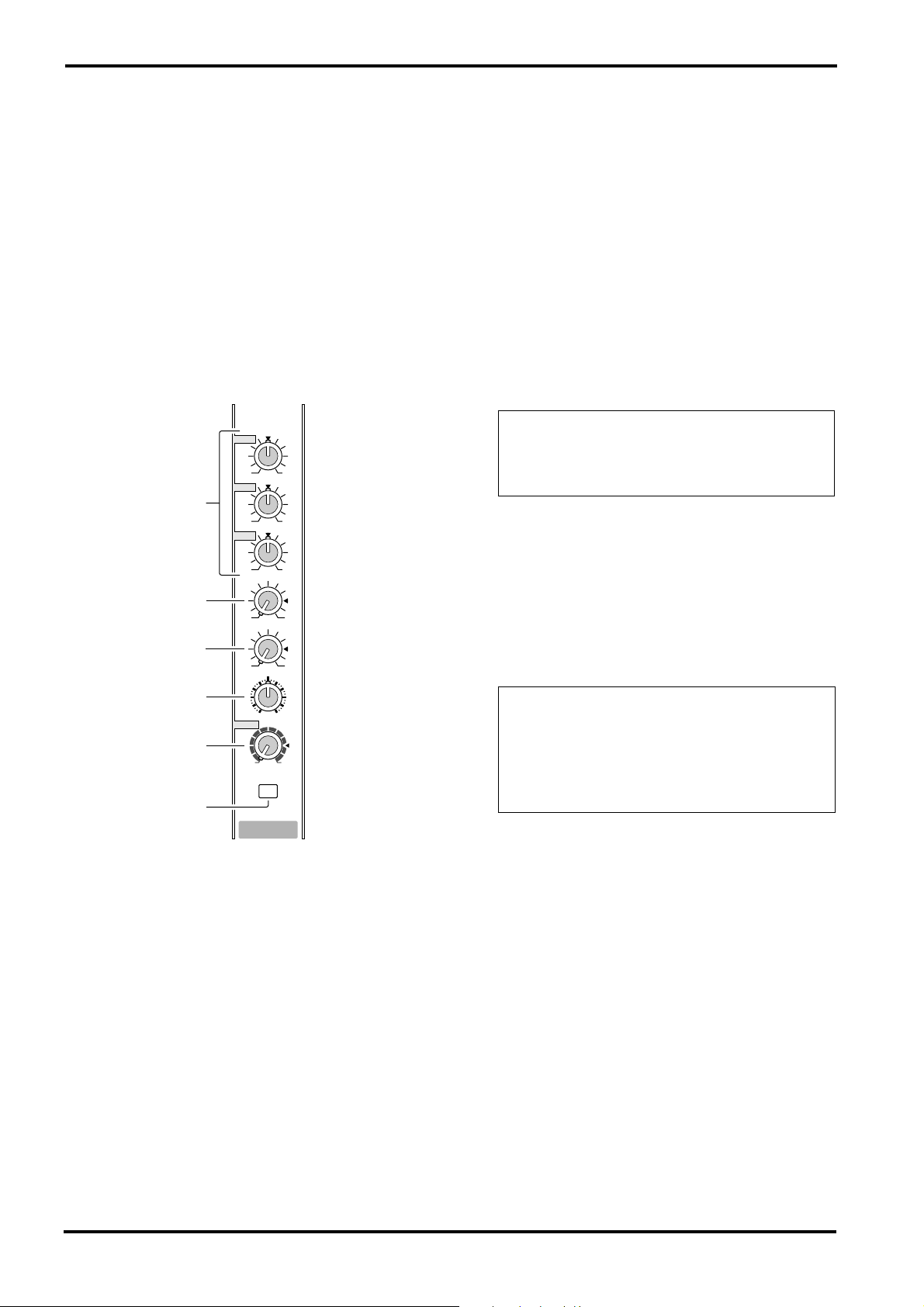
Channel section
Use these controls to adjust factors such as the
equalization, (frequency response), volume,
effect and monitor output level for the input signal to each channel.
1
HIGH
–15 +15
MID
1
–15 +15
LOW
–15 +15
MONI
2
010
EFFECT
3
010
PAN
4
LR
LEVEL
5
010
PAD
6
1
Equalizer controls (HIGH, MID, LOW)
1
This is a 3-band equalizer that adjusts the high
frequency range, mid frequency range, and low
frequency range of each channel. Response is flat
when the knobs are in the
toward the right will boost the corresponding frequency band, and rotating it toward the left will
cut it.
The base frequency (or center frequency), range
of boost or cut, and equalizer type of each band
are as follows.
HIGH: 10 kHz±15 dB shelving type
MID: 2.5 kHz±15 dB peaking type
LOW: 100 Hz±15 dB shelving type
▼
position. Rotating it
2
Monitor controls (MONI)
For each channel, this controls the amount of signal that is sent to the MONI bus.
The signal of the MONI bus is sent to the speakers connected to the MONITOR A/B jacks and to
the MONITOR jacks (input/output panel 6 ).
Note: The signal is sent to the MONITOR bus
from a location before the level control ( 5 ) of
each channel. This means that it will not be affected by the setting of the LEVEL control.
3
Effect control (EFFECT)
For each channel, this controls the amount of signal that is sent to the EFFECT bus.
The signal of the EFFECT bus passes through the
EFFECT section and the built-in digital effect,
and is sent to the external effect device connected
to the EFFECT OUT jacks (input/output panel
).
Note: The signal is sent to the EFFECT bus
from a location after the level control ( 5 ) of
each channel. This means that the amount of
signal that is sent to the EFFECT bus will be affected not only by the setting of the effect control, but also by the setting of the level control.
4
PAN control (BAL/PAN control for CH7/8)
This knob adjusts the stereo image (L/R) for each
channel. Adjust for equal volume on left and
right with a sound source input to the CH7 and 8
LINE connectors (L/R).
5
Level control (LEVEL)
This adjusts the output level for each channel.
6
Pad switch (PAD) (1–6 only)
This switch attenuates the input signal by 30 dB.
When connecting a line level device to channels
1–6, or if the mic input is distorted, turn this
switch on (the pressed-in position).
EMX860ST—Owner’s Manual
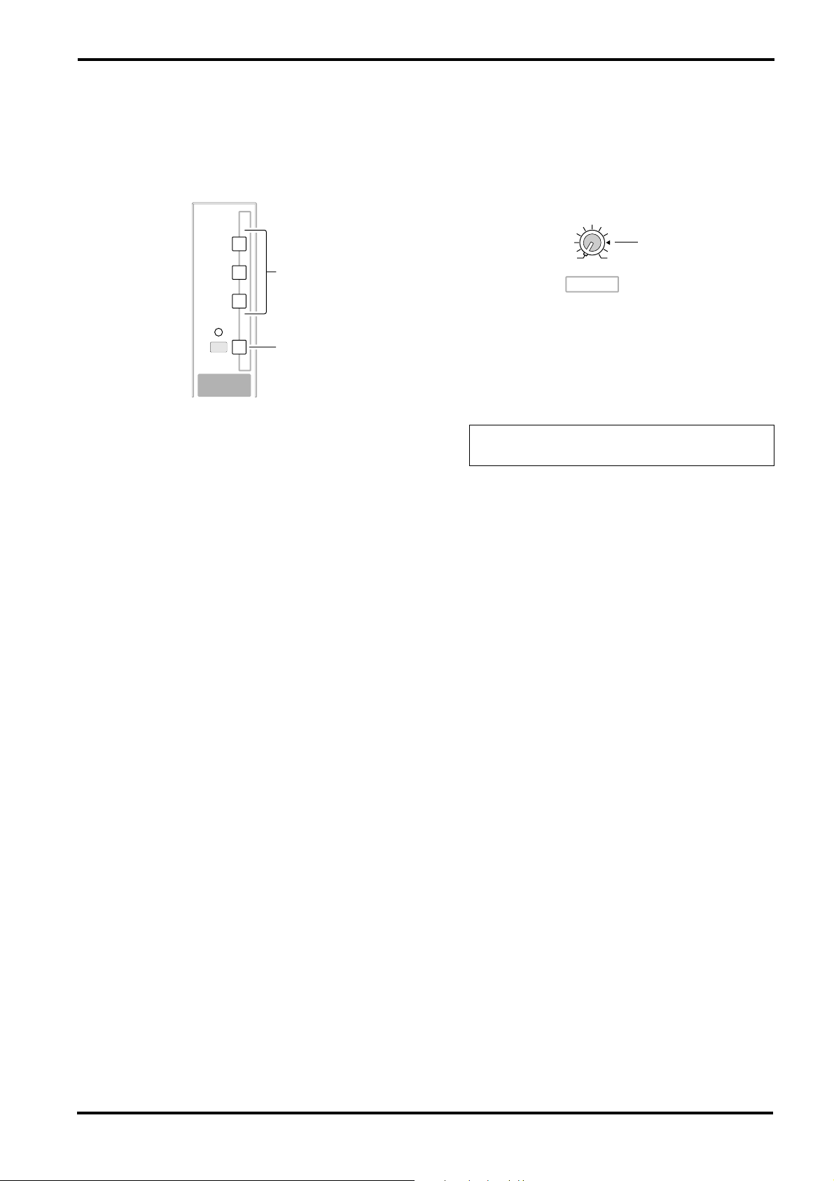
■
DIGITAL EFFECT section
This section allows you to turn the built-in digital
effect on/off and to select the effect type.
VOCAL
7
Effect select switch
L HALL
S HALL
ON
DIGITAL
EFFECT
7
8
Select the effect type for the built-in digital effect.
Control panel
■
EFFECT section
This section allows you to adjust the level of the
signal sent from the EFFECT bus to an external
effect device.
9
010
EFFECT OUT
EFFECT
9
EFFECT OUT control
This adjusts the effect send level for an external
effect device connected to the EFFECT OUT jack
(input/output panel 3 ).
Note: The EFFECT OUT control does not affect
the level sent to the built-in digital effect.
7
8
DIGITAL EFFECT ON switch
Use this switch to turn the digital effect on and
off. When this switch is on, the effect bus signal
processed with the built-in digital effect is sent to
the ST bus and MONI bus. The mix level of the
effect sound is adjusted with the EFFECT RTN
control in the MAIN and MONITOR sectins.
EMX860ST—Owner’s Manual
Front and rear panel
8
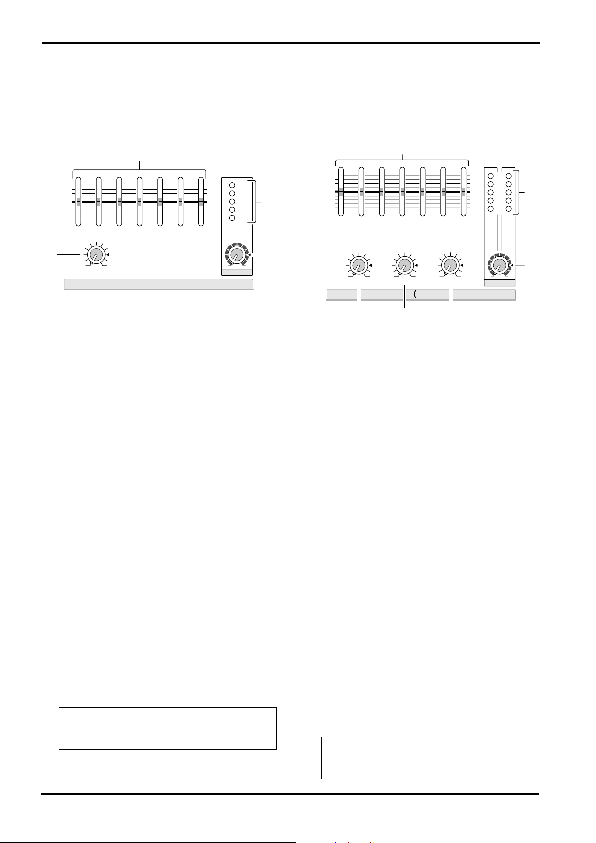
■
MONITOR section
■
MAIN section
This section allows you to adjust the tone and
volume of the MONITOR bus, and specify the
mix level of the built-in digital effect.
0
–12
•
6
•
0
•
6
•
+12
125 250 500 1k 2k 4k 8k
–12
+12
•
6
•
0
•
6
•
A
010
EFFECT RTN
MONITOR
0
Graphic equalizer
The EMX860ST has a 7-band graphic equalizer
for adjusting the frequency response of the
MONI bus signal. This allows you to cut or boost
each frequency band by a maximum of
You can use these sliders to reduce the level of frequency bands at which feedback easily occurs.
Frequency response is flat when a slider is in the
center position. Moving a slider in the positive
direction will boost, and in the negative direction
will cut.
These graphic equalizer settings affect both the
MONI bus signal output to the speakers and the
line level signal sent from MONITOR jack signal
(input/output panel 6 ).
A
EFFECT RTN control
This control adjusts the effect signal level sent to
the MONI bus from the built-in digital effect.
B
MASTER control
This control adjusts the MONI bus signal output
level.
This setting is output to both the front and rear
panel MONITOR jacks and appears in the MONI
bus signal.
C
Peak level indicator
This indicator allows you to monitor the level of
the signal which is output from the MONITOR
jack (input/output panel 6 ).
Note: To avoid distortion, adjust the MASTER
control ( B ) so that the 0 indicator lights occasionally.
010
MASTER
±
+6
+3
0
–5
–10
12dB.
C
B
This section allows you to adjust the tone and
volume of the ST bus, the mix level of the built-in
effect, and the mix level of the external input.
D
–12
•
6
•
0
•
6
•
+12
125 250 500 1k 2k 4k 8k
010010
EFFECT RTN AUX IN TAPE IN
E
D
Graphic equalizer
MAIN STEREO
F
010
The EMX860ST has a 7-band graphic equalizer
for adjusting the frequency response of the ST
bus signal. This allows you to cut or boost each
frequency band by a maximum of
These graphic equalizer settings affect both the
ST bus signal output to the speakers and the line
level signal output from the MAIN (STEREO)
jack (input/output panel 6 ).
E
EFFECT RTN control
Use this control to adjust the effect signal sent to the
ST bus from the built-in digital effect.
F
AUX IN control
This adjusts the amount of signal that is sent
from the AUX IN jack to the ST bus.
G
TAPE IN
This adjusts the amount of signal that is sent
from the TAPE IN jacks to the ST bus.
H
MASTER control
This control adjusts the ST bus signal output
level. This setting is output to the SPEAKERS L/
R/L+R, BRIDGE jacks and the MAIN (STEREO)
jack on the rear panel and appears in the ST bus
signal.
I
Peak level indicator
This indicator allows you to monitor the level of
the signal which is output from the MAIN (STEREO) jack (input/output panel 6 ).
Note: To avoid distortion, adjust the MASTER
control ( H ) so that the 0 indicator lights occasionally.
G
–12
•
6
•
0
•
6
•
+12
LR
010
MASTER
±
12dB.
+6
+3
–5
–10
0
I
H
EMX860ST—Owner’s Manual
 Loading...