

Yamaha Audio EMX660 User Manual
POWERED MIXER
E
Owner’s Manual
EEEngine
23344
1
HIGH
–15 +15
MID
–15 +15
LOW
–15 +15
MONI
010
EFFECT
010
LEVEL
010
PAD PAD PAD PAD
1
Hi-Z
Lo-Z
HIGH
–15 +15
MID
–15 +15
LOW
–15 +15
MONI
010
EFFECT
010
LEVEL
010
2
Hi-Z
Lo-Z
HIGH
–15 +15
MID
–15 +15
LOW
–15 +15
MONI
010
EFFECT
010
LEVEL
010
Hi-Z
Lo-Z
HIGH
–15 +15
MID
–15 +15
LOW
–15 +15
MONI
010
EFFECT
010
LEVEL
010
5
HIGH
–15 +15
MID
–15 +15
LOW
–15 +15
MONI
010
EFFECT
010
LEVEL
010
5
1
LINEHi-Z INST
MIC MICLo-Z
2
HIGH
–15 +15
MID
–15 +15
LOW
–15 +15
MONI
010
EFFECT
010
LEVEL
010
1
6
VO. ECHO 1
+12
•
6
•
VO. ECHO 2
0
•
6
•
–12
VO. REV. 1
VO. REV. 2
DIGITAL
6
EFFECT
2
EFFECT OUT
125
HALL. 1
010
EFFECT RTN
HALL. 2
ROOM
+12
•
6
PLATE
•
0
•
6
•
–12
ON
125
010010010
250 500 1k 2k 4k 8k
010
MONITOR
250 500 1k 2k 4k 8k
TAPE IN
AUX INEFFECT RTN
MAIN
FOOT SW
SEE REAR PANEL CAUTION
TAPE IN
EEEngine
+12
•
6
•
0
•
6
•
–12
MASTER
+12
•
6
•
0
•
6
•
–12
MASTER
+6
+3
0
–5
–10
010
+6
+3
0
–5
–10
010
AUX IN
POWER
ON
PHANTOM
OFF
2
A
MPs
300W 300W
1
LIMITER
MAIN
BRIDGE
MAIN
MAIN
POWER AMP
MONITOR
TAPE
REC
OUT
IN
11
22
INPUT OUTPUT
MAIN
MONITOR
MAIN
2

Precautions
• Do not allow water to enter this unit or allow the
unit to become wet. Fire or electrical shock may
result.
• Connect this unit’s power cord only to an AC
outlet of the type stated in this Owner’s Manual
or as marked on the unit. Failure to do so is a fire
and electrical shock hazard.
• Do not scratch, bend, twist, pull, or heat the
power cord. A damaged power cord is a fire and
electrical shock hazard.
• Do not place heavy objects, including this unit,
on top of the power cord. A damaged power cord
is a fire and electrical shock hazard. In particular,
be careful not to place heavy objects on a power
cord covered by a carpet.
• If you notice any abnormality, such as smoke,
odor, or noise, or if a foreign object or liquid gets
inside the unit, turn it off immediately. Remove
the power cord from the AC outlet. Consult your
dealer for repair. Using the unit in this condition
is a fire and electrical shock hazard.
• Should this unit be dropped or the cabinet be
damaged, turn the power switch off, remove the
power plug from the AC outlet, and contact your
dealer. If you continue using the unit without
heeding this instruction, fire or electrical shock
may result.
• If the power cord is damaged (i.e., cut or a bare
wire is exposed), ask your dealer for a replacement. Using the unit with a damaged power cord
is a fire and electrical shock hazard.
• Do not remove the unit’s cover. You could receive
an electrical shock. If you think internal inspection, maintenance, or repair is necessary, contact
your dealer.
Precautions
• This unit has ventilation holes at the rear to prevent the internal temperature rising too high. Do
not block them. Blocked ventilation holes are a
fire hazard.
• Clean the contacts of the phone plug before connecting it to the SPEAKERS jack of this unit.
Dirty contacts may generate heat.
• Use only speaker cables when connecting speakers to amplifier outputs. Using other types of
cables is a fire hazard.
Hold the power cord plug when disconnecting it
from an AC outlet. Never pull the cord. A damaged power cord is a potential fire and electrical
shock hazard.
• Do not touch the power plug with wet hands.
Doing so is a potential electrical shock hazard.
• The digital circuits of this unit may induce a
slight noise into nearby radios and TVs. If noise
occurs, relocate the affected equipment.
• Using a mobile telephone near this unit may
induce noise. If noise occurs, use the telephone
away from the unit.
• XLR-type connectors are wired as follows: pin 1:
ground, pin 2: hot (+), and pin 3: cold (-).
• Do not set all equalizer controls and faders to
maximum. Doing so may cause oscillation
depending on the condition of the connected
unit and speakers, and may damage the speakers.
• The performance of components with moving
contacts, such switches, rotary controls, faders,
and connectors, deteriorates over time. The rate
of deterioration depends on the operating environment and is unavoidable. Consult your dealer
about replacing defective components.
1
• Do not modify the unit. Doing so is a fire and
electrical shock hazard.
• When rack-mounting the unit, allow enough free
space around the unit for normal ventilation.
This should be: 30 cm at the sides, 30 cm behind,
and 40 cm above.
For normal ventilation during use, remove the
rear of the rack or open a ventilation hole.
If the airflow is not adequate, the unit will heat
up inside and may cause a fire.
EMX660—Owner’s Manual

Introduction
Introduction
Thank you for purchasing the Yamaha EMX660 Powered Mixer. The EMX660 has the following features.
In order to take full advantage of the EMX660 and enjoy long and trouble-free performance, please read this
owner’s manual carefully, and keep it in a safe place for future reference.
Features
• The EMX660 provides six input channels compatible with mic/line signals, including highimpedance input suitable for an electric-acoustic
guitar. The EMX660 has ample power, with a
maximum output of 300 W+300 W (600 W with
bridge connection), and is suitable for a wide
range of applications from installed systems to
small-scale PA systems.
• A two-channel power amp is built-in. The input
signals for the two channels can be selected as
MAIN+MAIN, MAIN+MONITOR, or MAIN
(bridge connection).
• Independent 7-band graphic EQ is provided for
both the MONITOR section and the MAIN section. This allows the volume and frequency
response to be adjusted separately for the main
speakers and monitor speakers.
Contents
Front and rear panel ...................................................4
Control panel ........................................................4
Input/output panel .................................................8
Rear panel ..........................................................10
Installation/Connection ............................................. 11
Installation ..........................................................11
Connection .........................................................11
Basic Operation ........................................................13
Connecting microphones and instruments .........13
Monitoring ........................................................... 13
Using the digital effect ........................................13
Example setups ........................................................14
As a conference PA system/installed
sound system .....................................................14
As a band PA ......................................................15
Troubleshooting .......................................................17
3
• The power amp section has a limiter circuit to
prevent sound distortion and protect the speakers.
• A digital effect with eight selectable effect types is
built-in.
A variety of effects can be applied to add reverberation or ambiance to vocals or instrumental
sounds.
Specifications ........................................................... 18
General specifications ........................................18
Input specifications..............................................19
Output specifications ..........................................19
Dimensions..........................................................20
Block and Level diagram.....................................21
EMX660—Owner’s Manual
6
Front and rear panel
4
Front and rear panel
Control panel
■
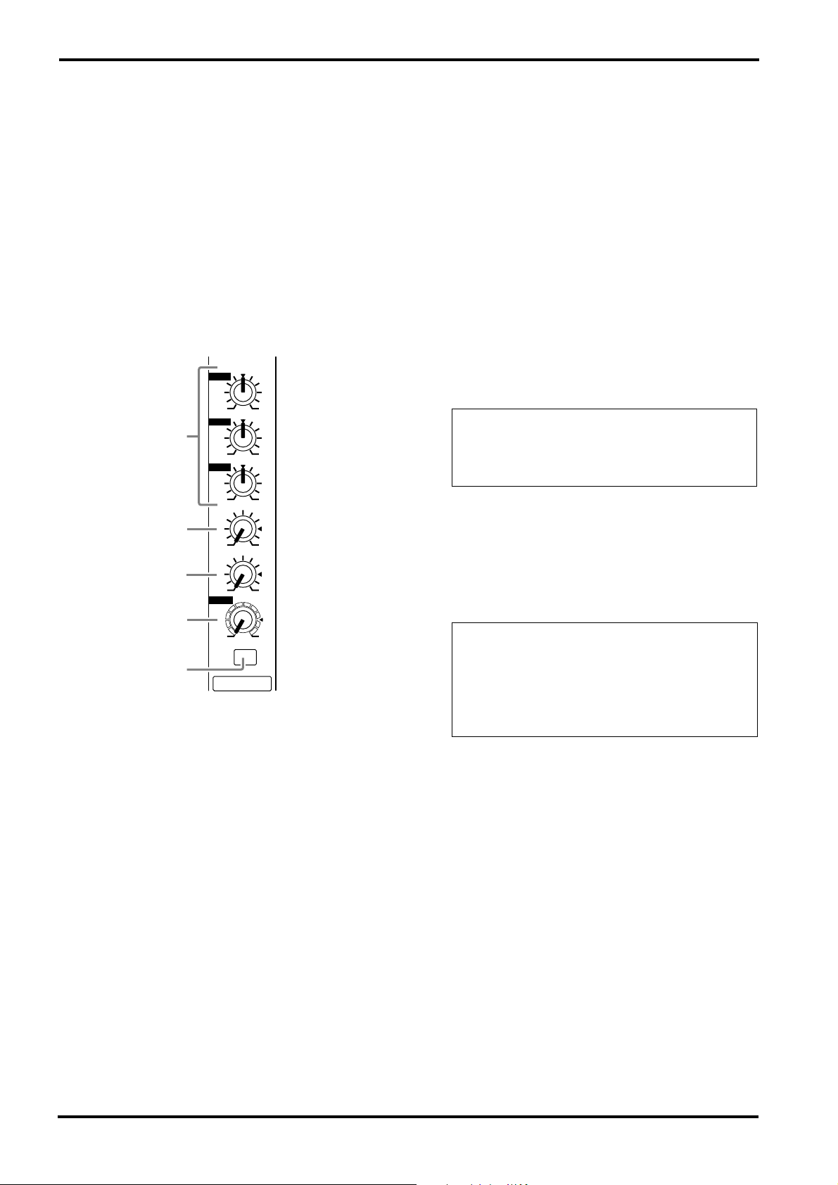
Channel section
In this section, you can adjust equalization (frequency response), volume level, effect and monitor output levels for the input signal of each
channel.
1
HIGH
–15 +15
MID
1
–15 +15
LOW
–15 +15
MONI
2
010
EFFECT
3
010
LEVEL
4
010
PAD
5
1
1
Equalizer controls (HIGH, MID, LOW)
This is a 3-band equalizer that adjusts the high
frequency range, mid frequency range, and low
frequency range of each channel. Response is flat
when the knobs are in the
toward the right will boost the corresponding frequency band, and rotating it toward the left will
cut it.
The base frequency (or center frequency), range
of boost or cut, and equalizer type of each band
are as follows.
HIGH: 12 kHz ±15 dB shelving type
MID: 2.5 kHz ±15 dB peaking type
LOW: 80 Hz ±15 dB shelving type
▼
position. Rotating it
2
Monitor controls (MONI)
For each channel, this controls the amount of signal that is sent to the MONITOR bus.
The signal of the MONITOR bus is sent to the
speakers connected to the POWER AMP 2 A/B
jacks (only if the power amp select switch is in the
MAIN-MONITOR position) and to the MONITOR jacks (input/output panel
).
Note: The signal is sent to the MONITOR bus
from a location before the level control ( 4 ) of
each channel. This means that it will not be affected by the setting of the LEVEL control.
Effect control (EFFECT)
3
For each channel, this controls the amount of signal that is sent to the EFFECT bus.
The signal of the EFFECT bus is sent to the builtin effect and to the EFFECT OUT jacks (input/
3
output panel
Note:
The signal is sent to the EFFECT bus
).
from a location after the level control (
each channel. This means that the amount of
signal that is sent to the EFFECT bus will be affected not only by the setting of the effect control, but also by the setting of the level control.
4
Level control (LEVEL)
This adjusts the output level for each channel.
Pad switch (PAD) (Channel 1–4 only)
5
This switch attenuates the input signal by 30 dB.
When connecting a line level device to channels
1–4, or if the mic input is distorted, turn this
switch on (the pressed-in position).
4
) of
EMX660—Owner’s Manual
A
■
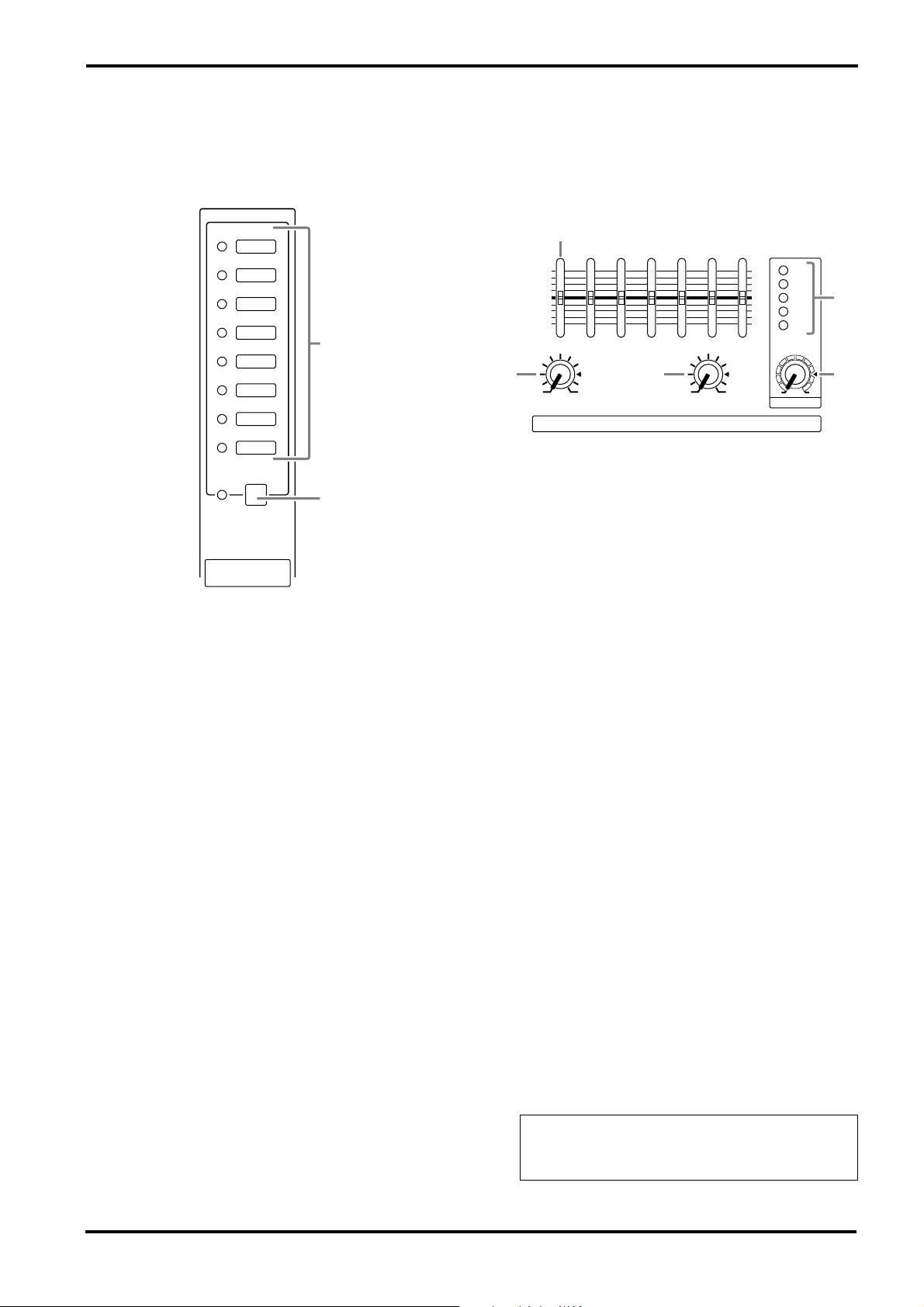
DIGITAL EFFECT section
This section allows you to turn the built-in digital
effect on/off and to select the effect type.
VO. ECHO 1
VO. ECHO 2
VO. REV. 1
VO. REV. 2
HALL. 1
HALL. 2
ROOM
PLATE
ON
6
7
DIGITAL
EFFECT
6
Effect select switch and indicator
Select the effect type for the built-in digital effect.
The indicator of the selected effect type lights up.
7
DIGITAL EFFECT ON switch and indicator
When this switch is on (pressed), the indicator
lights up and the built-in digital effect can be
used. In that case, the signal processed by the digital effect will be sent to the MAIN/MONITOR
bus. The mix level of the effect sound is adjusted
by the EFFECT RTN control of the MAIN and
MONITOR sections.
Control panel
■
MONITOR section
This section allows you to adjust the tone and
volume of the MONITOR bus, and specify the
mix level of the built-in effect and the external
input signals.
8
+12
•
6
•
0
•
6
•
–12
125
250 500 1k 2k 4k 8k
9
EFFECT RTN
010
0
010
TAPE IN
MONITOR
8
Graphic equalizer
This is a 7-band graphic equalizer that allows you
to adjust the frequency response of the MONITOR bus signal, providing a maximum of ±12 dB
of cut/boost for each frequency band. You can use
these sliders to reduce the level of frequency
bands at which feedback easily occurs. Frequency
response is flat when a slider is in the center position. Moving a slider in the positive direction will
boost, and in the negative direction will cut.
This graphic equalizer affects both the MONITOR bus signal that is output to the speakers and
the line level signal which is output from the
MONITOR jack (input/output panel
9
EFFECT RTN control
This controls the level of the effect sound which
is returned from the built-in digital effect to the
MONITOR bus.
0
TAPE IN control
This controls the level of the signal routed from
the TAPE IN jack to the MONITOR bus.
+12
•
6
•
0
•
6
•
–12
–10
010
MASTER
6
5
+6
+3
0
B
–5
A
).
A
MASTER control
This adjusts the final level of the MONITOR bus.
It affects both the MONITOR bus signal which is
output to the speakers and the line level signal
which is output to the MONITOR jack (input/
6
output panel
Peak level indicator
B
).
This indicator allows you to monitor the level of
the signal which is output from the MONITOR
6
jack (input/output panel
).
Note: To avoid distortion, adjust the MASTER
control (
) so that the 0 indicator lights occa-
sionally.
EMX660—Owner’s Manual
Front and rear panel
6
■
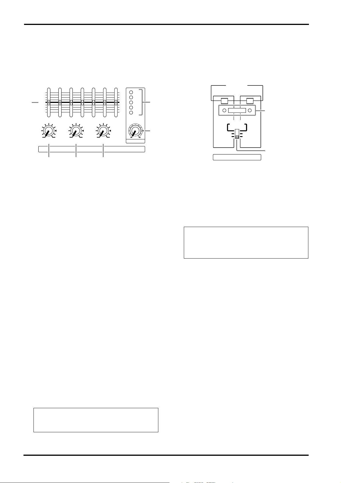
MAIN section
■
POWER AMP section
This section allows you to adjust the tone and
volume of the MAIN bus, the mix level of the
built-in effect, and the mix level of the external
input.
+12
•
6
•
0
C
•
6
•
–12
125
250 500 1k 2k 4k 8k
010010010
AUX INEFFECT RTN
TAPE IN
+12
•
6
•
0
•
6
•
–12
010
MASTER
MAIN
D
Graphic equalizer
C
E
F
This is a 7-band graphic equalizer that allows you
to adjust the frequency response of the MAIN
bus signal, providing a maximum of ±12 dB of
cut/boost for each frequency band.
This graphic equalizer affects both the MAIN bus
signal that is output to the speakers and the line
level signal which is output from the MAIN jack
6
(input/output panel
EFFECT RTN control
D
).
This adjusts the level of the effect signal which is
returned from the built-in digital effect to the
MAIN bus.
E
AUX IN control
This adjusts the amount of signal that is sent
from the AUX IN jack to the MAIN bus.
F
TAPE IN
This adjusts the amount of signal that is sent
from the TAPE IN jacks to the MAIN bus.
G
MASTER control
This adjusts the final level of the MAIN bus. It
affects both the MAIN bus signal which is output
from the speakers, and the line level signal which
is output from the MAIN jack (input/output
6
panel
H
Peak level indicator
).
This indicator allows you to monitor the level of
the signal which is output from the MAIN jack
(input/output panel 6 ).
Note:
To avoid distortion, adjust the MASTER
control (G) so that the 0 indicator lights occasionally.
+6
+3
–5
–10
This section allows you to select the signals that
will be output from the built-in two-channel
power amplifier, and to select the BRIDGE mode.
2A
MPs
300W 300W
0
H
G
1
MAIN
MAIN
LIMITER
BRIDGE
MAIN
2
MAIN
MONITOR
I
J
POWER AMP
I
LIMITER indicator
This indicator lights up when the level of the signal output from the power amp section reaches
the maximum and the limiter is activated. Adjust
appropriate control so that the indicator lights up
for only a short while when the signal reaches the
maximum level.
Note: The indicator lights up or flashes for a
longer duration if the power amp section is significantly overloaded, which could result in
malfunction. Avoid such a situation.
J
Power amp select switch
Select one of the following three settings to specify the signals that will be output from power
amp 1/2.
• MAIN BRIDGE
With this setting, the MAIN bus signal will be
output from the BRIDGE jack. The two power
amp channels (A and B) will be bridge con-
G
nected. Only the MASTER control
MAIN section becomes effective.
•
MAIN-MAIN
With this setting, the MAIN bus signal will be
output from the POWER AMP 1 A/B jacks and
from the POWER AMP 2 A/B jacks. Only the
G
MASTER control
in the MAIN section
becomes effective.
• MAIN-MONITOR
With this setting, the MAIN bus signal will be
output from the POWER AMP 1 A/B jacks and
the MONITOR bus signal is output from the
POWER AMP 2 A/B jacks. Only the MASTER
controls in the MAIN and MONITOR sections
G, A
are both effective.
in the
EMX660—Owner’s Manual

■
POWER indicator & PHANTOM
switch
ON
OFF
POWER
PHANTOM
L
K
K
POWER indicator
This indicator will light when the power of the
EMX660 is turned on.
L
PHANTOM switch
This switch turns the phantom power supply on/
off for the Lo-Z input jacks of channels 1–4 and
MIC input jacks of channels 5–6.
Turn this switch off if you do not use it.
Control panel
7
EMX660—Owner’s Manual
 Loading...