

Yamaha Audio EMX640 User Manual

POWERED MIXER
Owner’s Manual
Introduction
Thank you for purchasing the Yamaha EMX640 Powered Mixer. The EMX640 has the following features.
In order to take full advantage of the EMX640 and enjoy long and trouble-free performance, please read this
owner’s manual carefully, and keep it in a safe place for future reference.
Features
• Six input channels compatible with mic/line signals are
provided. The EMX640 has ample power, with a maximum
output of 200 W+200 W (400 W with bridge connection),
and is suitable for a wide range of applications from installed
systems to small-scale PA systems.
• A two-channel power amp is built-in. The input signals for
the two channels can be selected as MAIN+MAIN,
MAIN+MONITOR, or MAIN (bridge connection).
• Independent 7-band graphic EQ is provided for both the
MONITOR section and the MAIN section. This allows the
volume and frequency response to be adjusted separately for
the main speakers and monitor speakers.
• Two limiter circuits are built-in to prevent excessive input
levels to the amp.
• A digital effect with three selectable effect types is built-in.
A variety of effects can be applied to add reverberation or
ambiance to vocals or instrumental sounds.
Precautions
1. Avoid excessive heat, humidity, dust and vibration
Keep the unit away from locations where it is likely to be
exposed to high temperatures or humidity — such as near
radiators, stoves, etc. Also avoid locations which are subject
to excessive dust accumulation or vibration which could
cause mechanical damage.
2. Ventilation
Allow a distance of 30 cm between the unit and the wall so
that heat generated from the unit will be released effectively.
Also, allow enough space between the unit and other devices.
If you mount the unit in an audio rack, keep a space of 40
cm on the top panel, and a space of 15 cm to the side panel.
Remove the rear panel of the rack or open a vent hole. If heat
release is inadequate, the unit will retain heat inside the unit,
which may cause a fire.
3. A void physical shocks
Strong physical shocks to the unit can cause damage. Handle
it with care.
4. Do not open the case or attempt repairs or modifications
yourself
This product contains no user-serviceable parts. Refer all
Contents
Front and rear panel ............................................2
Control panel .......................................................... 2
Input/output panel .................................................. 6
Rear panel .............................................................. 7
Connections.........................................................8
Basic Operation ...................................................9
Connecting microphones and instruments ............ 9
Using the digital effect............................................ 9
Example setups .................................................10
As a conference PA system/installed sound system 10
As a band PA........................................................ 11
Specifications.....................................................13
General specifications.......................................... 13
Input specifications............................................... 14
Output specifications............................................ 14
Dimensions........................................................... 15
Block and Level diagram ...................................... 15
maintenance to qualified Yamaha service personnel. Opening
the case and/or tampering with the internal circuitry voids
the warranty.
5. Always power off before making connections
Always turn the power OFF before connecting or
disconnecting cables. This is important to prevent damage to
the unit itself as well as other connected equipment.
6. Handle cables carefully
Always plug and unplug cables — including the AC power
cord — by gripping the connector, not the cord.
7. Clean with a soft dry cloth
Never use solvents such as benzine or thinner to clean the
unit. Wipe clean with a soft, dry cloth.
8. Always use the correct power supply
Make sure that the power supply voltage specified on the rear
panel matches your local AC mains supply. Also make sure
that the AC mains supply can deliver more than enough
current to handle all equipment used in your system.
9. Do not touch the heatsink when the EMX640 is in use.
It can get very hot.
E
Front and rear panel
2
Front and rear panel
Control panel
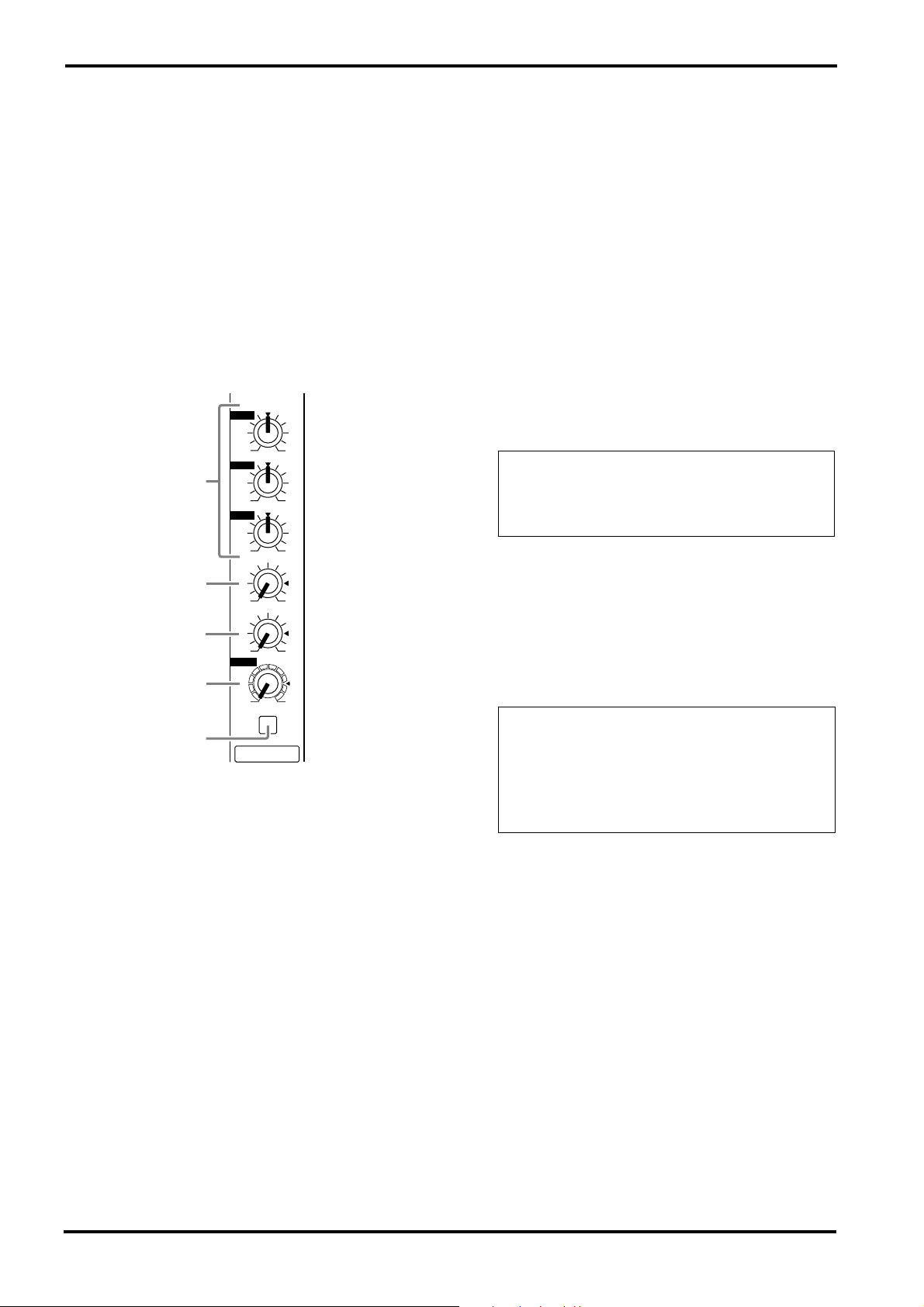
■
Channel section
In this section, you can adjust equalization (frequency response), volume level, effect and monitor output levels for the input signal of each
channel.
1
HIGH
–15 +15
MID
1
–15 +15
LOW
–15 +15
MONI
2
010
EFFECT
3
010
LEVEL
4
010
PAD
5
1
1
Equalizer controls (HIGH, MID, LOW)
This is a 3-band equalizer that adjusts the high
frequency range, mid frequency range, and low
frequency range of each channel. Response is flat
when the knobs are in the
toward the right will boost the corresponding frequency band, and rotating it toward the left will
cut it.
The base frequency (or center frequency), range
of boost or cut, and equalizer type of each band
are as follows.
HIGH: 12 kHz
MID: 2.5 kHz
LOW: 80 Hz
▼
position. Rotating it
±
15 dB shelving type
±
15 dB peaking type
±
15 dB shelving type
2
Monitor controls (MONI)
For each channel, this controls the amount of signal that is sent to the MONITOR bus.
The signal of the MONITOR bus is sent to the
speakers connected to the POWER AMP 2 A/B
jacks (only if the power amp select switch is in the
MAIN+MONITOR position) and to the MONITOR jacks (input/output panel 6 ).
Note: The signal is sent to the MONITOR bus
from a location before the level control ( 4 ) of
each channel. This means that it will not be affected by the setting of the LEVEL control.
Effect control (EFFECT)
3
For each channel, this controls the amount of signal that is sent to the EFFECT bus.
The signal of the EFFECT bus passes through the
EFFECT section and the built-in effect, and is
sent to the external effect device connected to the
EFFECT OUT jacks (input/output panel 3 ).
Note: The signal is sent to the EFFECT bus
from a location after the level control ( 4 ) of
each channel. This means that the amount of
signal that is sent to the EFFECT bus will be affected not only by the setting of the effect control, but also by the setting of the level control.
4
Level control (LEVEL)
This adjusts the output level for each channel.
5
Pad switch (PAD) (1~4 only)
This switch attenuates the input signal by 30 dB.
When connecting a line level device to channels
1~4, or if the mic input is distorted, turn this
switch on (the pressed-in position).
EMX640—Owner’s Manual

■
DIGITAL EFFECT section
This section allows you to turn the built-in digital
effect on/off and to select the effect type.
VOCAL
L HALL
S HALL
ON
DIGITAL
EFFECT
6
Effect select switch
Select the effect type for the built-in digital effect.
DIGITAL EFFECT ON switch
7
When this switch is on (pressed), the digital effect
built into the EMX640 can be used. In that case,
the signal processed by the digital effect will be
sent to the MAIN/MONITOR bus. The mix level
of the effect sound is adjusted by the EFFECT
RTN control of the MAIN and MONITOR sections.
6
7
Control panel
■
EFFECT section
This section allows you to adjust the level of the
signal sent from the EFFECT bus to an external
effect device.
8
EFFECT OUT
EFFECT
8
EFFECT OUT control
This adjusts the effect send level for an external
effect device connected to the EFFECT OUT jack
(input/output panel 3 ).
Note: The EFFECT OUT control does not affect
the send level to the built-in effect.
3
EMX640—Owner’s Manual
Front and rear panel
4
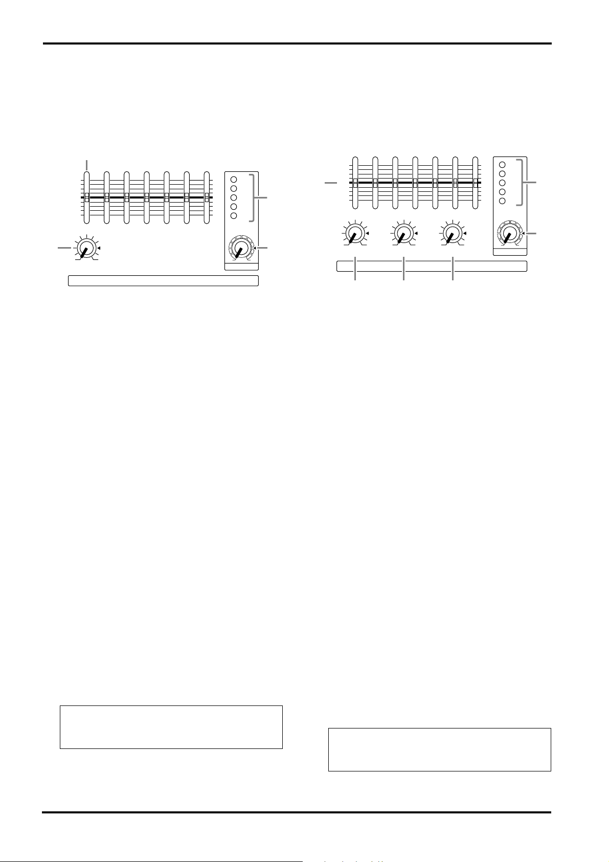
■
MONITOR section
■
MAIN section
This section allows you to adjust the tone and
volume of the MONITOR bus, and specify the
mix level of the built-in effect.
9
+12
–12
•
6
•
0
•
6
•
125
250 500 1k 2k 4k 8k
+12
–12
•
6
•
0
•
6
•
–10
0
EFFECT RTN
MONITOR
9
Graphic equalizer
This is a 7-band graphic equalizer that allows you
to adjust the frequency response of the MONITOR bus signal, providing a maximum of ±12 dB
of cut/boost for each frequency band. You can use
these sliders to reduce the level of frequency
bands at which feedback easily occurs. Frequency
response is flat when a slider is in the center position. Moving a slider in the positive direction will
boost, and in the negative direction will cut.
This graphic equalizer affects both the MONITOR bus signal that is output to the speakers and
the line level signal which is output from the
MONITOR jack (input/output panel 6 ).
0
EFFECT RTN control
This controls the level of the effect sound which
is returned from the built-in digital effect to the
MONITOR bus.
MASTER control
A
This adjusts the final level of the MONITOR bus.
It affects both the MONITOR bus signal which is
output to the speakers and the line level signal
which is output to the MONITOR jack (input/
output panel 6 ).
Peak level indicator
B
This indicator allows you to monitor the level of
the signal which is output from the MONITOR
jack (input/output panel 6 ).
Note: To avoid distortion, adjust the MASTER
control ( A ) so that the 0 indicator lights occasionally.
MASTER
This section allows you to adjust the tone and
volume of the MAIN bus, the mix level of the
built-in effect, and the mix level of the external
input.
+6
+12
•
6
+6
+3
0
B
–5
C
–12
•
0
•
6
•
125
250 500 1k 2k 4k 8k
+12
–12
•
+3
6
•
0
0
•
6
•
–5
–10
H
G
A
AUX INEFFECT RTN
D
Graphic equalizer
C
E
This is a 7-band graphic equalizer that allows you
to adjust the frequency response of the MAIN
bus signal, providing a maximum of
cut/boost for each frequency band.
This graphic equalizer affects both the MAIN bus
signal that is output to the speakers and the line
level signal which is output from the MAIN jack
(input/output panel 6 ).
EFFECT RTN control
D
This adjusts the level of the effect signal which is
returned from the built-in digital effect to the
MAIN bus.
E
AUX IN control
This adjusts the amount of signal that is sent
from the AUX IN jack to the MAIN bus.
F
TAPE IN
This adjusts the amount of signal that is sent
from the TAPE IN jacks to the MAIN bus.
G
MASTER control
This adjusts the final level of the MAIN bus. It
affects both the MAIN bus signal which is output
from the speakers, and the line level signal which
is output from the MAIN jack (input/output
panel 6 ).
H
Peak level indicator
This indicator allows you to monitor the level of
the signal which is output from the MAIN jack
(input/output panel 6 ).
Note: To avoid distortion, adjust the MASTER
control ( G ) so that the 0 indicator lights occasionally.
MAIN
TAPE IN
F
MASTER
±
12 dB of
EMX640—Owner’s Manual
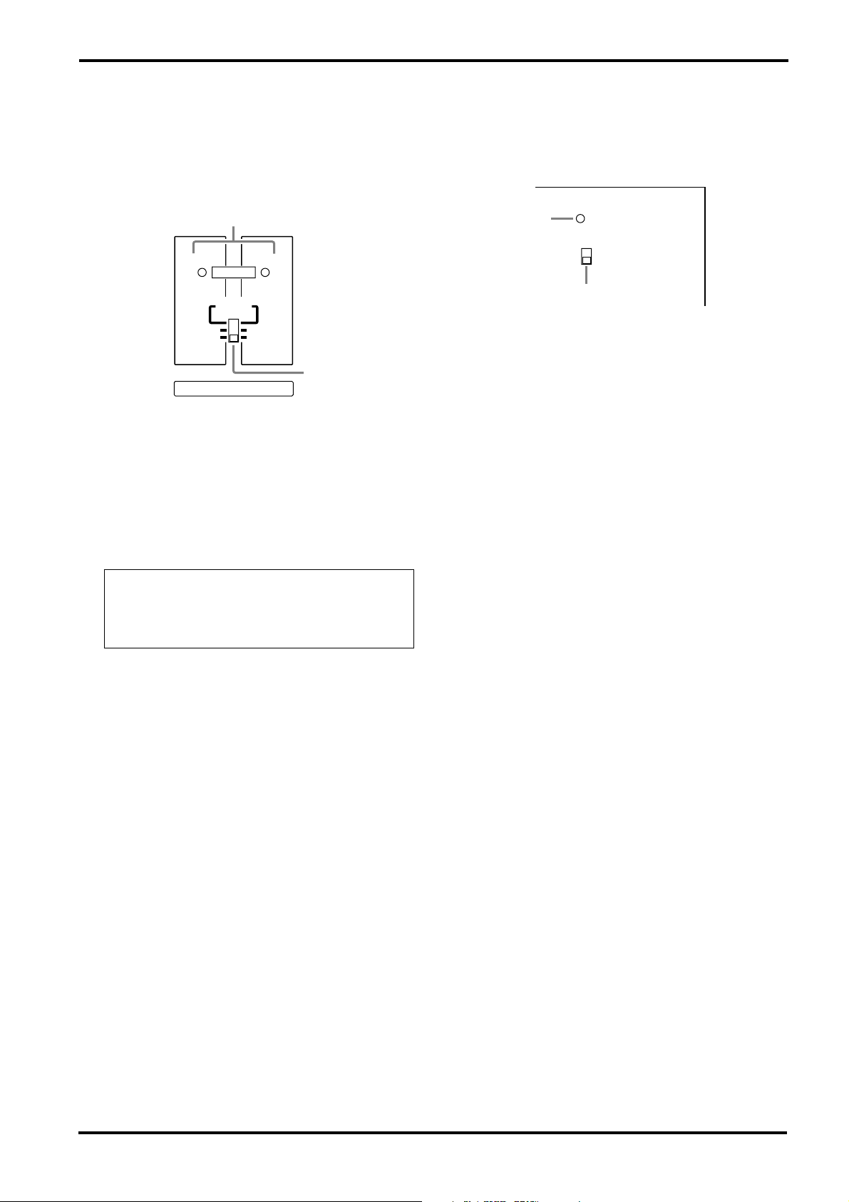
■
POWER AMP section
This section allows you to select the signals that
will be output from the built-in two-channel
power amplifier, and to select the BRIDGE mode.
I
1
MAIN
MAIN
LIMITER
BRIDGE
MAIN
2
MAIN
MONITOR
J
POWER AMP
I
LIMITER indicator
This indicator lights up when the level of the signal output from the power amp section reaches
the maximum and the limiter is activated. Adjust
appropriate control so that the indicator lights up
for only a short while when the signal reaches the
maximum level.
Control panel
■
POWER indicator & PHANTOM
switch
K
K
POWER indicator
This indicator will light when the power of the
EMX640 is turned on.
L
PHANTOM +48 V switch
This switch turns the phantom power supply on/
off for the Lo-Z input jacks of channels 1~4 and
MIC input jacks of channels 5~6.
ON
OFF
L
POWER
PHANTOM +48V
5
Note: The indicator lights up or flashes for a
longer duration if the power amp section is significantly overloaded, which could result in
malfunction. Avoid such a situation.
J
Power amp select switch
Select one of the following three settings to specify the signals that will be output from power
amp 1/2.
• MAIN-MONITOR
With this setting, the MAIN and MONITOR sections can be used independently. The MAIN bus
signal will be output from the POWER AMP 1 A/
B jacks, and the MONITOR bus signal will be
output from the POWER AMP 2 A/B jacks.
• MAIN-MAIN
With this setting, the two power amp channels
can be used independently. The MAIN bus signal
will be output from the POWER AMP 1 A/B jacks
and from the POWER AMP 2 A/B jacks.
• MAIN BRIDGE
With this setting, the two power amp channels (A
and B) will be bridge connected. Only the MAIN
bus signal will be output from the BRIDGE jack,
though.
EMX640—Owner’s Manual
Front and rear panel
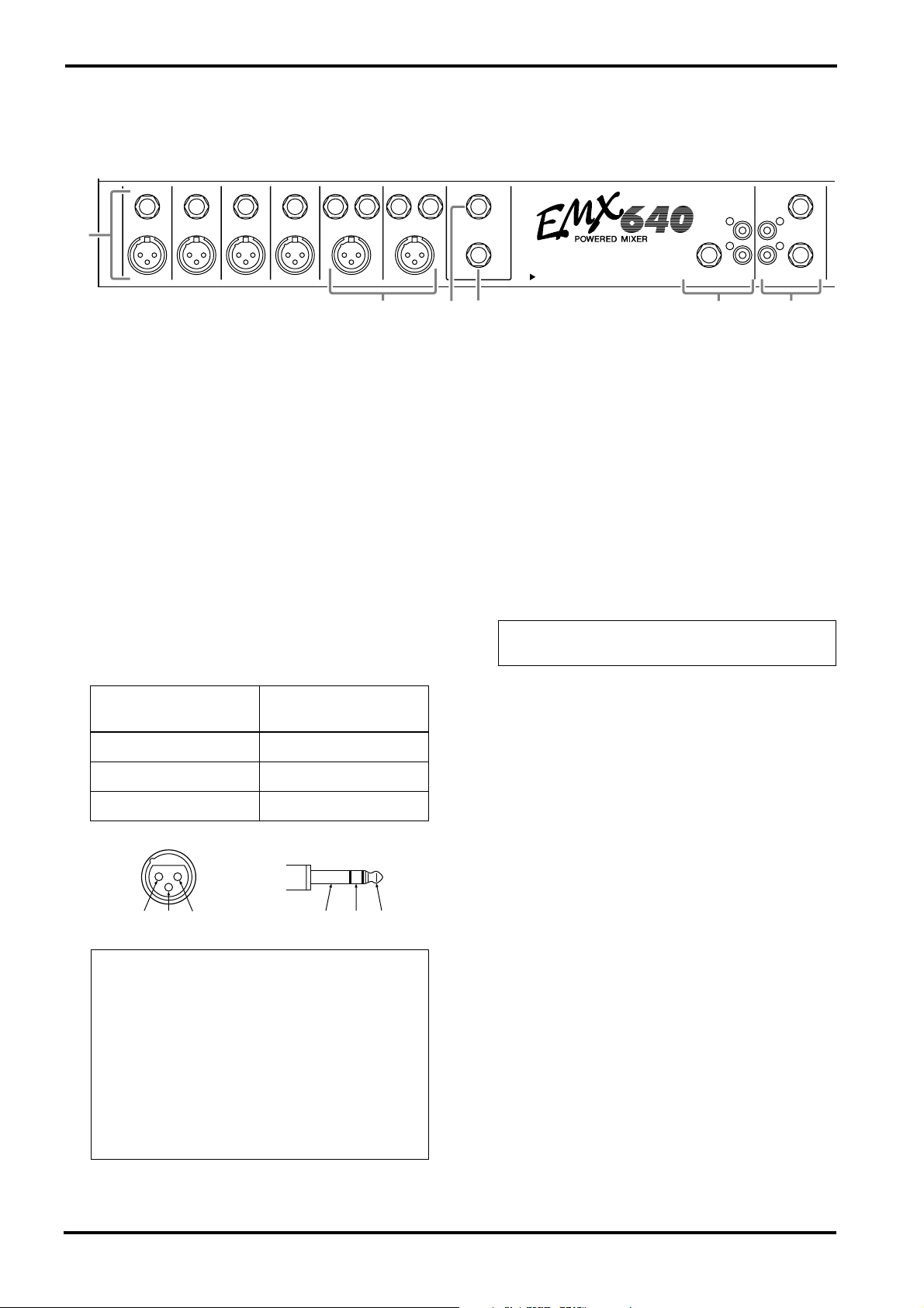
6
Input/output panel
1
Hi-Z
1
1
Lo-Z
Channel input jacks (Hi-Z, Lo-Z) 1~4
Hi-Z
Lo-Z
Hi-Z
Lo-Z
LINEHi-Z LINE
MIC MICLo-Z
These are the input jacks for channels 1~4. By
using the PAD switches (control panel 5 ) you
can connect any of the jacks to a wide range of
sources from mics to line level devices (synthesizers or rhythm boxes etc.). The Lo-Z jacks can
provide +48 V phantom power, allowing you to
use condenser microphones.
Both Hi-Z and Lo-Z are balanced, and are compatible with microphones of output impedance
50~600
Ω
or line level devices of 600
Ω
. The nominal input level is –40 dB~–10 dB for the Hi-Z
jacks, and –50 dB~–20 dB for the Lo-Z jacks.
Pin connections for the Hi-Z and Lo-Z jacks are
as follows.
Lo-Z jacks
(XLR type)
Hi-Z jacks
(TRS phone jacks)
Pin 1: ground Sleeve: ground
Pin 2: hot (+) Tip: hot (+)
Pin 3: cold (–) Ring: cold (–)
RST
+-
GND
GND
Note: It is not possible to simultaneously use
both the Hi-Z and Lo-Z inputs of a given channel. For each channel, use only one of the inputs
as appropriate for the input source.
Phantom power is switched on/off in simultaneously for channels 1~6. For this reason,
devices which do not require phantom power
must be connected to the Hi-Z or LINE jacks if
the PHANTOM +48 V switch (control panel
L) is on.
1
2
2
2
EFFECT OUT
FOOT SW
43
2
REC
TAPE
OUT
IN
AUX IN
SEE REAR PANEL CAUTION
INPUT TO MAIN OUTPUT
5 6
Channel input jacks (MIC/LINE) 5~6
MONITOR
MAIN
These are the input jacks for channels 5~6.
Microphones can be connected to the MIC jacks,
and stereo line level devices (such as synthesizers
or rhythm boxes) can be connected to the LINE
jacks.
The MIC jacks are balanced, and are compatible
with microphones of output impedance
50~600
are compatible with line level devices of 600
Ω
. The LINE jacks are unbalanced, and
Ω
output impedance. Nominal input level is –50 dB
for the MIC jacks and –20 dB for the LINE jacks.
Note: It is possible to simultaneously use both
the MIC and LINE inputs for a given channel.
Effect output jack (EFFECT OUT)
3
The input of an external effect such as a delay or
echo can be connected to this jack. The signal
adjusted by the EFFECT control of each channel
will be sent to the EFFECT bus, its level adjusted
by the EFFECT OUT control, and output from
this jack.
The nominal output level and impedance are
+4 dB/10 k
4
Foot switch jack (FOOT SW)
+-
A separately sold Yamaha FC5 foot switch can be
connected to this jack. If a foot switch is con-
Ω
.
nected to this jack, you can use your foot to
switch the built-in digital effect on/off. The Digital Effect ON switch on the front panel must be
set to ON in order to use a foot switch.
External input jacks (AUX IN/TAPE IN)
5
These are input jacks that allow the signal from
an external device to be added to the MAIN output. Monaural output devices such as external
effects can be connected to the AUX IN jack, and
stereo output devices such as cassette recorder or
CD players can be connected to the TAPE IN
jacks.
EMX640—Owner’s Manual
 Loading...