

Yamaha Audio EMX3500 User Manual
Powered Mixer
Tables de mixage á amplification de puissance
Aktiv-Mischpult
Operation Manual
Manuel d'instructions
Bedienungsanleitung
A
INPUT
B
I/O
2 3
1
1 2 3 4 5 6 7 8 9 10 11 12 13 14 15 16
A
A
B
B
PAD
PAD
-16 -60
-15 +15
250 5k
-15 +15
-15 +15
PAD
20dB
20dB
20dB
PEAK
PEAK
SIGNAL
SIGNAL
SIGNAL
-16 -60
-16 -60
GAIN
GAIN
GAIN
80
80
80
-15 +15
-15 +15
HIGH
HIGH
HIGH
250 5k
250 5k
MID FREQ
MID FREQ
MID FREQ
-15 +15
-15 +15
MID
MID
-15 +15
-15 +15
LOW
LOW
010
MONITOR
010
EFFECT 1
010
EFFECT 2
LR
ON
LOW
010
010
MONITOR
MONITOR
010
010
EFFECT 1
EFFECT 1
010
010
EFFECT 2
EFFECT 2
LR
LR
PAN
PAN
ON
ON
0
0
5
5
10
10
15
15
20
20
30
30
40
40
50
50
60
60
1
2 3 4 5 6 7 8 9 10 11 12 13 14 15
4
A
A
B
B
PAD
20dB
PEAK
PEAK
SIGNAL
-16 -60
GAIN
80
-15 +15
HIGH
250 5k
MID FREQ
-15 +15
MID
MID
-15 +15
LOW
010
MONITOR
010
EFFECT 1
010
EFFECT 2
LR
PAN
PAN
ON
0
0
5
5
10
10
15
15
20
20
30
30
40
40
50
50
60
60
5 6 7 8 9
A
A
A
B
PAD
20dB
SIGNAL
-16 -60
GAIN
80
-15 +15
HIGH
250 5k
MID FREQ
-15 +15
MID
-15 +15
LOW
010
MONITOR
010
EFFECT 1
010
EFFECT 2
LR
PAN
ON
PAD
20dB
PEAK
SIGNAL
-16 -60
GAIN
80
-15 +15
HIGH
250 5k
MID FREQ
-15 +15
-15 +15
LOW
010
MONITOR
010
EFFECT 1
010
EFFECT 2
LR
ON
0
5
10
15
20
30
40
50
60
A
B
B
B
PAD
PAD
20dB
20dB
PEAK
PEAK
PEAK
SIGNAL
SIGNAL
-16 -60
-16 -60
GAIN
GAIN
80
80
-15 +15
-15 +15
HIGH
HIGH
250 5k
250 5k
MID FREQ
MID FREQ
-15 +15
-15 +15
MID
MID
MID
-15 +15
-15 +15
LOW
LOW
010
010
MONITOR
MONITOR
010
010
EFFECT 1
EFFECT 1
010
010
EFFECT 2
EFFECT 2
LR
LR
PAN
PAN
PAN
ON
ON
0
0
5
5
10
10
15
15
20
20
30
30
40
40
50
50
60
60
10 11 12 13 14 15 16
A
A
A
B
PAD
PAD
20dB
20dB
PEAK
SIGNAL
SIGNAL
-16 -60
-16 -60
GAIN
GAIN
80
80
-15 +15
-15 +15
HIGH
HIGH
250 5k
250 5k
MID FREQ
MID FREQ
-15 +15
-15 +15
MID
-15 +15
-15 +15
LOW
LOW
010
010
MONITOR
MONITOR
010
010
EFFECT 1
EFFECT 1
010
010
EFFECT 2
EFFECT 2
LR
LR
PAN
ON
ON
0
0
5
5
10
10
15
15
20
20
30
30
40
40
50
50
60
60
A
B
B
B
PAD
PAD
20dB
20dB
PEAK
PEAK
PEAK
SIGNAL
SIGNAL
-16 -60
-16 -60
GAIN
GAIN
80
80
-15 +15
-15 +15
HIGH
HIGH
250 5k
250 5k
MID FREQ
MID FREQ
-15 +15
-15 +15
MID
MID
MID
-15 +15
-15 +15
LOW
LOW
010
010
MONITOR
MONITOR
010
010
EFFECT 1
EFFECT 1
010
010
EFFECT 2
EFFECT 2
LR
LR
PAN
PAN
PAN
ON
ON
0
0
0
5
5
5
10
10
10
15
15
15
20
20
20
30
30
30
40
40
40
50
50
50
60
60
60
A
B
PAD
20dB
PEAK
SIGNAL
-16 -60
GAIN
80
-15 +15
HIGH
250 5k
MID FREQ
-15 +15
MID
-15 +15
LOW
010
MONITOR
010
EFFECT 1
010
EFFECT 2
LR
PAN
ON
A
B
PAD
20dB
PEAK
SIGNAL
-16 -60
GAIN
80
-15 +15
HIGH
250 5k
MID FREQ
-15 +15
MID
-15 +15
LOW
010
MONITOR
010
EFFECT 1
010
EFFECT 2
LR
PAN
ON
0
5
10
15
20
30
40
50
60
CD IN
EFFECT RETURN +4dB
AB
-6dB
L
L
R
R
A
REC OUT
TAPE IN
-10dBV
-10dBV
LRL
BALANCED
B
CH
INSERT I/O
0dB
OUTIN
A
A
B
B
PAD
PAD
20dB
20dB
PEAK
PEAK
SIGNAL
SIGNAL
-16 -60
-16 -60
GAIN
GAIN
80
80
-15 +15
-15 +15
HIGH
HIGH
250 5k
250 5k
MID FREQ
MID FREQ
-15 +15
-15 +15
MID
MID
-15 +15
-15 +15
LOW
LOW
010
010
MONITOR
MONITOR
010
010
EFFECT 1
EFFECT 1
010
010
EFFECT 2
LR
0
5
10
15
20
30
40
50
60
010
EFFECT 2
MONITOR
LR
010
PAN
PAN
EFFECT RETURN 1 EFFECT RETURN 2
ON
ON
0
0
5
5
10
10
15
15
20
20
30
30
40
40
50
50
60
60
16
R
INSERT
L
VOCAL HALL/ROOM INSTRUMENT
DLY (ms)
VOCAL ECHO 1
DLY (ms)
VOCAL ECHO 2
REV (s)
VOCAL REVERB 1
REV (s)
VOCAL REVERB 2
DLY (ms)
REVERB & ECHO 1
DLY (ms)
REVERB & ECHO 2
PEAK
ON
PRESET
DIGITAL EFFECT (EFFECT 2)
+12
9
6
3
0
3
EQ
6
9
-12
63 125 250 500 1k 2k 4k 8k 16k
STEREO GRAPHIC EQUALIZER
010
010
MONITOR
MONITOR A
010
010
MONITOR B
LEVEL
LEVEL
0
0
5
5
10
10
15
15
20
20
30
30
40
40
50
50
60
60
1—EFFECT SEND—2LR PHONESST
EFFECT SEND +4dB
1L/
2L/
MONO
MONO
1R
2R12
LINE INSERT I/O +4dB MONITOR OUT +4dB
LRLRA
PRE GEQ POST GEQ
RST
REV (s)
LARGE HALL
SHARE GATE
REV (s)
SMALL HALL
SHARE REVERB
REV (s)
CHURCH
DELAY L, R
SIZE
ROOM
SHORT DELAY
PITCH CHORUS
PARAMETER
POWERED MIXER
010
REC OUT
010
010
TAPE IN
CD IN
A
B
0
0
5
5
10
10
15
15
20
20
30
30
40
40
50
50
60
60
B
PROGRAM RESET
DLY (ms)
REV (s)
DLY (ms)
DLY (ms)
DETUNE
+12
9
6
3
0
3
6
9
-12
PHANTOM
ON
OFF
010
PHONES
EMX3500m R0 1 AP
Printed in Korea
P.O. Box 1, Hamamatsu, Japan

CONGRATULATIONS!
Your Yamaha EMX3500 Powered Mixer is an ideal choice for medium-scale PA and sound reinforcement applications. The
EMX3500 is available in 12- and 16-channel models, each of which features a high-performance stereo power amplifier that
delivers a powerful 350 watts per channel into 4-ohm loads.
Each input channel offers a choice of balanced low-impedance XLR or TRS phone jack inputs, and a 20-dB pad switch and
input gain control allow precise level matching with any input source. The response of each channel signal can be independently shaped by a three-band equalizer with variable mid-range frequency. Also, each channel has dual EFFECT controls
and a MONITOR control that make possible convenient incorporation of external effects and monitoring systems, and a PAN
control that can be used to pan the channel signal across the master stereo bus.
The EFFECT 2 control also feeds the EMX3500’s internal effects processor, which is one of the highlights of the EMX series.
This sophisticated Yamaha digital signal processor provides 15 top-quality digital effects, each of which has a programmable
parameter that can be adjusted to create precisely the required sound.
In addition to the internal DSP controls, the EMX3500’s master control section includes: a nine-band stereo graphic equalizer that allows overall output response shaping and feedback control in sound reinforcement applications; paired master
stereo faders; master EFFECT SEND faders; and EFFECT RETURN controls, which allow the returned effect signals to be
sent to the monitor system as well as the stereo bus. There are separate level controls for the dual monitor outputs, and a
level control for headphone output. Finally, there are level controls for input from and output to a recording tape deck, and a
level control for two pairs of selectable CD IN jacks that allow input from CD players or similar sound sources.
In addition to line-insert I/O jacks for each channel, the EMX3500 offers both pre-GEQ and post-GEQ line insertion to the
master stereo bus. These connectors, when combined with the dual effects circuits, give the EMX3500 a formidable degree
of signal-processing versatility. In addition, +48V phantom power is provided for convenient powering of condenser microphones.
We urge you to read this operation manual thoroughly in order to get the best performance out of the mixer’s many features
and controls. Please keep the manual in a safe place for later reference.

FCC INFORMATION (U.S.A.)
1. IMPORTANT NOTICE: DO NOT MODIFY THIS UNIT!
This product, when installed as indicated in the instructions contained in this manual, meets FCC requirements. Modifications not expressly approved by Yamaha
may void your authority, granted by the FCC, to use the product.
2. IMPORTANT: When connecting this product to accessories and/or another product use only high quality shielded cables. Cable/s supplied with this product MUST
be used. Follow all installation instructions. Failure to follow instructions could void your FCC authorization to use this product in the USA.
3. NOTE: This product has been tested and found to comply with the requirements listed in FCC Regulations, Part 15 for Class "B" digital devices. Compliance with
these requirements provides a reasonable level of assurance that your use of this product in a residential environment will not result in harmful interference with other
electronic devices. This equipment generates/uses radio frequencies and, if not installed and used according to the instructions found in the users manual, may cause
interference harmful to the operation of other electronic devices. Compliance with FCC regulations does not guarantee that interference will not occur in all
installations. If this product is found to be the source of interference, which can be determined by turning the unit "OFF" and "ON", please try to eliminate the problem
by using one of the following measures:
Relocate either this product or the device that is being affected by the interference.
Utilize power outlets that are on different branch (circuit breaker of fuse) circuits or install AC line filter/s.
In the case of radio or TV interference, relocate/reorient the antenna. If the antenna lead-in is 300 ohm ribbon lead, change the lead-in to coaxial type cable.
If these corrective measures do not produce satisfactory results, please contact the local retailer authorized to distribute this type of product. If you can not locate the
appropriate retailer, please contact Yamaha Corporation of America, Electronic Service Division, 6600 Orangethorpe Ave, Buena Park, CA 90620
* This applies only to products distributed by YAMAHA CORPORATION OF AMERICA.
IMPORTANT NOTICE FOR
THE UNITED KINGDOM
Connecting the Plug and Cord
WARNING: THIS APPARATUS MUST BE EARTHED
IMPORTANT: The wires in this mains lead are coloured in accordance with
the following code:
GREEN-AND-YELLOW : EARTH
BLUE : NEUTRAL
BROWN: LIVE
As the colours of the wires in the mains lead of this apparatus may not
correspond with the coloured markings identifying the terminals in your plug,
proceed as follows:
The wire which is coloured GREEN and YELLOW must be connected to the
terminal in the plug which is marked by the letter E or by the safety earth
symbol or coloured GREEN and YELLOW.
The wire which is coloured BLUE must be connected to the terminal which is
marked with the letter N or coloured BLACK.
The wire which is coloured BROWN must be connected to the terminal which
is marked with the letter L or coloured RED.
* This applies only to products distributed by YAMAHA KEMBLE
MUSIC (U.K.) LTD.
ADVARSEL!
Lithiumbatteri–Eksplosionsfare ved fejlagtig håndtering.
Udskiftning må kun ske med batteri af samme fabrikat og type.
Levér det brugte batteri tilbage til leverandoren.
VARNING
Explosionsfara vid felaktigt batteribyte. Använd samma batterityp
eller en ekvivalent typ som rekommenderas av apparattillverkaren.
Kassera använt batteri enligt fabrikantens instruktion.
VAROITUS
Paristo voi räjähtää, jos se on virheellisesti asennettu. Vaihda
paristo ainoastaan laitevalmistajan suosittelemaan tyyppiin. Hävitä
käytetty paristo valmistajan ohjeiden mukaisesti.
1

CONTENTS
PRECAUTIONS ...............................................................................................................3
CONTROLS AND CONNECTORS ..................................................................................4
Front Panel: Input Channel Controls ..........................................................................4
Front Panel: Master Control Section ........................................................................... 6
Top Panel ...................................................................................................................8
Rear Panel ............................................................................................................... 10
OPERATING TIPS ......................................................................................................... 11
Cautions for Connected Sources ..............................................................................11
Matching Input Levels............................................................................................... 11
Setting Channel and Master Faders .........................................................................11
Using the Channel Equalizers .................................................................................. 12
Using the Digital Signal Processor ...........................................................................12
Using the Graphic Equalizer .....................................................................................13
Connecting Speakers ...............................................................................................13
CONNECTION EXAMPLE .............................................................................................14
SPECIFICATIONS .........................................................................................................15
Input Characteristics .................................................................................................16
Output Characteristics ..............................................................................................16
Console Dimensions ................................................................................................17
BLOCK AND LEVEL DIAGRAMS .................................................................................. 18
2

PRECAUTIONS
Please keep the following points in mind when installing and operating your Yamaha EMX3500 Powered Mixer. Also be sure
to read the precautions in the Operating Tips section before using the EMX3500.
• AVOID EXCESSIVE HEAT, HUMIDITY, DUST, AND VIBRATION
Keep the EMX3500 away from locations (such as near radiators, stoves, etc.) where it is likely to be exposed to high
temperatures or humidity. Also avoid locations where the mixer may be exposed to excessive dust accumulation or
vibration that could cause mechanical damage.
• INSTALL IN A WELL-VENTILATED LOCATION
The internal circuitry of the EMX3500 produces heat that can become a potential fire hazard if not properly ventilated.
When setting up the EMX3500 for operation, be sure to leave at least 10 cm between it and any adjacent walls or surrounding equipment.
• AVOID PHYSICAL SHOCKS
Do not drop the EMX3500 or subject it other strong physical shocks, as doing so can damage the it. Handle the mixer with
care, and transport it in a suitable hard case or flight case.
• DO NOT OPEN THE UNIT OR ATTEMPT REPAIRS OR MODIFICATIONS YOURSELF
The EMX3500 contains no user-serviceable parts. Refer all maintenance and repairs to qualified Yamaha service personnel. Opening the case and/or tampering with the internal circuitry will void the warranty.
• MAKE SURE THE POWER IS OFF BEFORE MAKING OR REMOVING CONNECTIONS
Always turn the power OFF before connecting or disconnecting cables. If you insert or remove cables with the power on,
you run the risk of damaging both the mixer and any connected equipment.
• HANDLE CABLES CAREFULLY
Always plug and unplug cables (including the AC power cable) by gripping the connector, not the cord itself.
• CLEAN WITH A SOFT, DRY CLOTH
Never use solvents such as benzine or thinner to clean the EMX3500. Should the mixer become dirty, wipe it clean with a
soft, dry cloth.
• ALWAYS USE THE CORRECT POWER SOURCE
Make sure that the power requirements on the rear panel of the EMX3500 match your local AC mains supply.
• KEEP SPEAKER PLUGS CLEAN
Solid phone plugs can overheat when inserted in the rear-panel SPEAKER jacks of the EMX3500, causing a potential fire
hazard. Make a habit of checking the metal tips of your speaker plugs, and cleaning them if necessary, before connecting
them to the EMX3500.
3
CONTROLS AND CONNECTORS
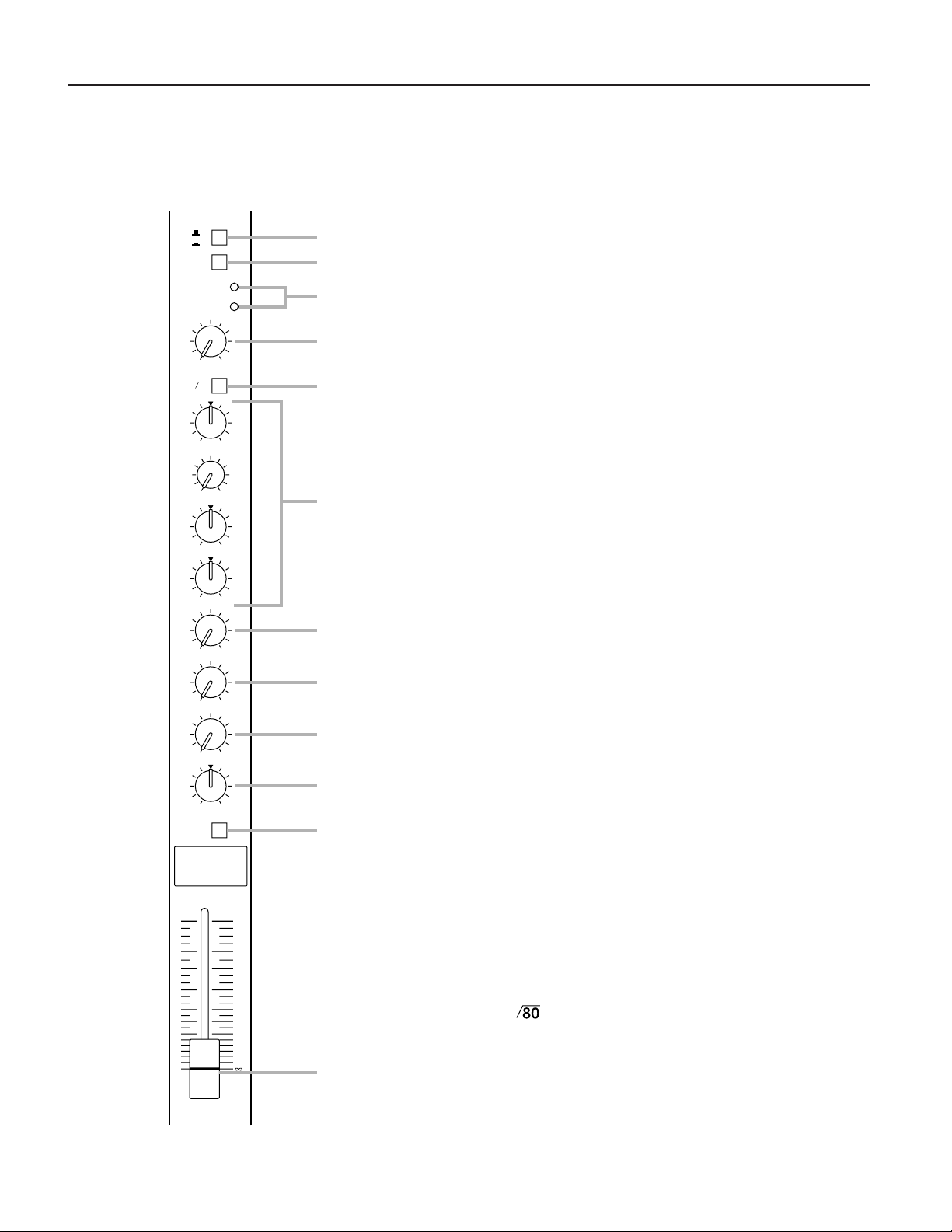
Front Panel: Input Channel Controls
1 Input selector switch
16
A
B
PAD
20dB
PEAK
SIGNAL
1
2
3
This switch selects the input connector via which the
source is connected to the channel. Leave the switch
out if the source is connected via the A (balanced XLR)
input connector. Push it in when the source is connected via the B (balanced 1/4" phone) connector.
-16 -60
GAIN
80
-15 +15
HIGH
250 5k
MID FREQ
-15 +15
MID
-15 +15
LOW
010
MONITOR
010
EFFECT 1
010
EFFECT 2
LR
PAN
ON
16
4
2 PAD switch
This switch attenuates the signal applied to channel (at
5
the corresponding A input connector or B input jack on
the top panel) by 20 dB prior to the head amplifier and
input gain control. This feature can be used to prevent
high-level signals from overloading the input circuitry,
allowing the mixer to handle a wider range of input
6
signal levels.
3 SIGNAL and PEAK LED indicators
These two LED indicators let you check the level of the
signal input to the channel. The green SIGNAL indicator lights when a signal of 10 dB below the nominal
7
channel level is received. The red PEAK indicator lights
when the input signal reaches 3 dB below the
channel’s clipping point. Both of these indicators show
8
the level of the post-EQ/pre-fader signal. If the PEAK
indicator lights more than briefly on high-level tran-
9
sients, you should use the PAD switch or the GAIN
control to decrease the input sensitivity of the channel.
If this does not work, reduce the output level of the
0
A
connected source.
4 GAIN control
This control adjusts the channel’s input sensitivity
between –60 dB and –16 dB when the PAD switch is
off, or between –40 dB and +4 dB when the PAD
0
5
10
15
20
30
40
50
60
B
switch is on. Continuously variable gain control allows
optimum adjustment to virtually any microphone or line
source.
5
HPF switch
This switch causes the channel to be filtered through
an HPF with a 12 dB/octave roll-off at 80 Hz. This
feature is useful for reducing low-frequency noise such
as an AC mains hum or wind noise.
4
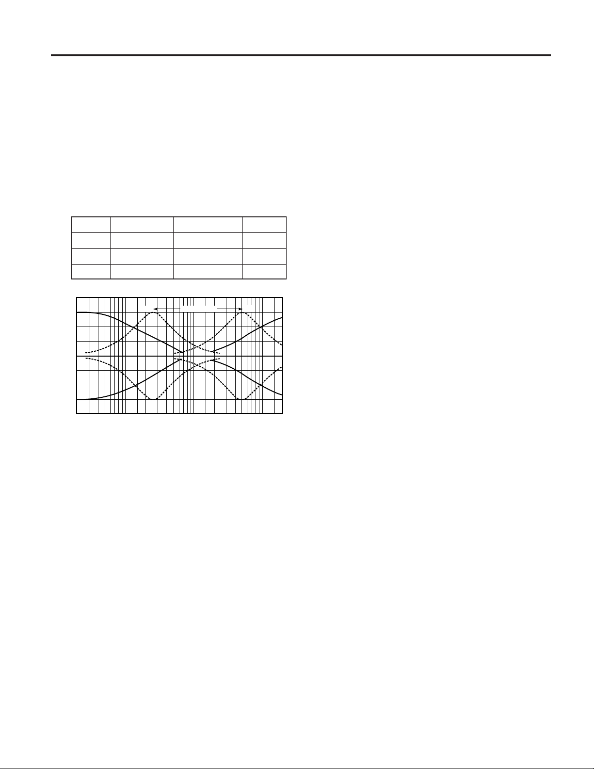
6 Equalizer controls
This set of four controls allows you to individually
modify the channel’s response. Each channel of the
EMX3500 is equipped with a three-band equalizer (EQ)
that has shelving HIGH and LOW controls, and a
peaking MID control with a sweepable center frequency (which is adjusted by the MID FREQ control).
Refer to “Using the Channel Equalizers” on page 12 for
details on the use of these controls.
9 EFFECT 2 control
This control determines the level of the post-EQ/postfader signal that is sent from the channel to the Effect 2
mixing bus. The channel signals mixed by this bus are
sent via the EFFECT SEND 2 fader to the EFFECT
SEND 2 jack on the top panel . The output signal is
also fed into the EMX3500’s internal digital signal
processor. Thus, a signal fed to the Effect 2 bus using
this control can be processed externally or internally.
Control Max. boost/cut Frequency Type
HIGH ±15 dB 12 kHz Shelving
MID ±15 dB 250 Hz to 5 kHz Peaking
LOW ±15 dB 80 Hz Shelving
20
MIDFREQ2505k
10
0
Response(dB)
-10
-20
20501002005001k2k5k10k20k
Frequency(Hz)
7 MONITOR control
This control determines the level of the post-EQ/prefader signal that is sent from the channel to the monitor
mixing bus. All signals sent to the Monitor bus are
mixed, then fed to the two MONITOR OUT jacks on the
top panel after their final output levels have been set by
the MONITOR A and B controls in the master control
section.
8 EFFECT 1 control
This control determines the level of the post-EQ/postfader signal that is sent from the channel to the Effect 1
mixing bus. The channel signals mixed by this bus
have their overall level set by the EFFECT SEND 1
fader, then are sent to the EFFECT SEND 1 jack. The
output from this jack can be processed by an external
effect device.
0 PAN control
This control pans the channel signal across the master
L and R buses, thus determining the perceived position
of the sound from that channel in the output stereo
sound field. If a PAN control is set all the way to the
left, for example, the sound from that channel will be
heard from the left speaker system only. If it is set all
the way to the right, the sound will be heard from the
right speaker system only. Intermediate settings will
cause the sound to appear at corresponding locations
in the stereo sound field.
A Channel ON switch
This switch enables input from the channel to the
mixing buses. When turned off (that is, when the button
is out), the channel will be removed from the mix.
Turning off unneeded channels may help to minimize
noise during quite passages.
B Channel fader
This is the channel’s main level control. It determines
the level of the signal that is sent from the channel to
the master mixing and effect buses. It is the settings of
the input channel faders that determine the “mix,” or
the balance of sound levels between the instruments or
other sources connected to the inputs. When a channel
is not being used, its fader should be set at the minimum position to prevent the addition of unwanted noise
to the main program signal.
5
 Loading...