

Yamaha Audio EMX2000 User Manual
Owner’s Manual
MIC MIC MIC MIC MIC MIC MIC MIC
INPUT OUTPUT
LINELINELINE
INS
I/O
GAIN
HIGH
MID
LOW
MONI 1
MONI 2
EFFECT
PAN
10
15
20
25
30
40
50
∞
INS
I/O
GAIN
–34+10
–16
–16
–60
HIGH
+15–15
MID
+15–15
LOW
+15–15
MONI 1
100
MONI 2
100
EFFECT
100
PAN
L
L
R
PFL
PFL
0
0
5
5
10
15
20
25
30
40
50
∞
2
1
INS
INS
I/O
I/O
GAIN
GAIN
–34+10
–34+10
–60
+15–15
+15–15
+15–15
100
100
100
R
HIGH
MID
LOW
MONI 1
MONI 2
EFFECT
PAN
10
15
20
25
30
40
50
∞
–16
–16
–60
HIGH
+15–15
MID
+15–15
LOW
+15–15
MONI 1
100
MONI 2
100
EFFECT
100
PAN
L
R
PFL
0
0
5
5
10
15
20
25
30
40
50
∞
3
0dB
INSERT I/O
OUT IN
GAIN
GAIN
GAIN
–34+10
–16
–60
HIGH
+15–15
MID
+15–15
LOW
+15–15
MONI 1
100
MONI 2
100
EFFECT
100
PAN
L
R
PFL
0
5
10
15
20
25
30
40
50
∞
4
–34+10
–34+10
–60
+15–15
+15–15
+15–15
100
100
100
L
R
PFL
5
HIGH
MID
LOW
MONI 1
MONI 2
EFFECT
PAN
10
15
20
25
30
40
50
∞
–16
–16
–60
PEAK
PEAKPEAKPEAKPEAKPEAKPEAK
HIGH
+15–15
MID
+15–15
LOW
+15–15
MONI 1
100
MONI 2
100
EFFECT
100
PAN
L
L
R
PFL
0
0
5
5
10
15
20
25
30
40
50
∞
6
ST R
MONO
ST
VOCAL REVERB 1
5
VOCAL REVERB 2
6
VOCAL REVERB 3
7
VOCAL REVERB 4
8
FOOT SW
MONO
+4dB
EFFECT
+4dB
PHONES/
C-R OUT
EEEngine
(+4dB)
PEAK
+8
POWER
+5
+3
+4+18
+1
PHANTOM
(+48V)
0
ON
–1
OFF
–3
–5
PHONES/C.R.OUT
–7
–10
–15
100
10
15
20
25
30
40
50
∞
MAXMINPROGRAM
0
5
LR
HALL 1
9
HALL 2
10
HALL 3
11
ROOM
12
AFLAFLAFL
100
–20
ST 2
ST1
100
PLATE 1
13
PLATE 2
14
PLATE 3
15
GATE REVERB
16
8k4k2k1k500250125
+12
6
ON
0
6
–12
0
5
10
15
20
25
30
40
50
∞
R
L
L
REC
–10dBV
0
8
7
6
5
4
3
2
1
16
L
R
1
L
100
L/BRIDGE
MONI 1
MONI 2
10
ON
9
10
1
VOCAL ECHO 1
11
VOCAL ECHO 2
2
12
13
VOCAL ECHO 3
3
14
VOCAL ECHO 4
4
15
0
5
10
15
20
25
30
40
50
∞
ST 1
+4dB
R
ST 2
+4dB
MONIMONI
2
+4dB
PAMP
IN
+4dB+4dB+4dB BRIDGE
POWER AMPTAPE IN
LR
LIMITER
LEVEL
+4+18
ST L
MONO BRIDGE
100
GRAPHIC EQUALIZER
0
5
10
15
20
25
30
40
50
∞
11 L
12 R
GAIN
HIGH
MID
LOW
MONI 1
MONI 2
EFFECT
BAL
10
15
20
25
30
40
50
∞
L
11 L
B
TAPE
R
12 R
B
L
L
(MONO)
(MONO)
A
A
A
B
–34+10
PEAKPEAKPEAK
+15–15
+15–15
+15–15
100
100
100
L
R
PFL
0
5
11/12
RR
R
ST
ST
SUB 2
SUB 1
ST
MONI 1
100
MONI 2
PFL
100
MONI 1
ST
100
PFL
DIGITAL EFFECT
ST SUB 1
MONI 1
100
MONI 2
100
+12
ST
6
0
6
100
–12
PFL
ST SUB 2
AFL AFL
0
5
10
15
20
25
30
40
50
∞
MONI 1 MONOST 1EFFECTMONI 2
9 L
B
10 R
B
LINELINELINELINELINE
9 L
(MONO)
(MONO)
A
10 R
A
11/12
9/10
87654321
A
B
GAIN
GAIN
–34+10
–34+10
–16
–60
HIGH
+15–15
MID
+15–15
LOW
+15–15
MONI 1
100
MONI 2
100
EFFECT
100
PAN
R
PFL
0
5
10
15
20
25
30
40
50
∞
7
–34+10
–60
HIGH
+15–15
+15–15
MID
+15–15
+15–15
LOW
+15–15
+15–15
MONI 1
100
100
MONI 2
100
100
EFFECT
100
100
BAL
L
L
R
R
PFL
PFL
0
5
10
15
20
25
30
40
50
∞
9/10
8
E

FCC INFORMATION (U.S.A.)
1. IMPORTANT NOTICE: DO NOT MODIFY THIS UNIT! This
product, when installed as indicated in the instructions contained in
this manual, meets FCC requirements. Modifications not expressly
approved by Yamaha may void your authority, granted by the FCC, to
use the product.
2. IMPORTANT: When connecting this product to accessories and/or
another product use only high quality shielded cables. Cable/s supplied
with this product MUST be used. Follow all installation instructions.
Failure to follow instructions could void your FCC authorization to use
this product in the USA.
3. NOTE: This product has been tested and found to comply with the
requirements listed in FCC Regulations, Part 15 for Class “B” digital
devices. Compliance with these requirements provides a reasonable
level of assurance that your use of this product in a residential
environment will not result in harmful interference with other
electronic devices. This equipment generates/uses radio frequencies
and, if not installed and used according to the instructions found in the
users manual, may cause interference harmful to the operation of other
electronic devices. Compliance with FCC regulations does not
guarantee that interference will not occur in all installations. If this
product is found to be the source of interference, which can be
determined by turning the unit “OFF” and “ON”, please try to
eliminate the problem by using one of the following measures:
Relocate either this product or the device that is being affected by the
interference. Utilize power outlets that are on different branch (circuit
breaker or fuse) circuits or install AC line filter/s. In the case of radio
or TV interference, relocate/reorient the antenna. If the antenna lead-in
is 300 ohm ribbon lead, change the lead-in to coaxial type cable. If
these corrective measures do not produce satisfactory results, please
contact the local retailer authorized to distribute this type of product. If
you can not locate the appropriate retailer, please contact Yamaha
Corporation of America, Electronic Service Division, 6600
Orangethorpe Ave, Buena Park, CA 90620
This applies only to products distributed by YAMAHA CORPORATION OF AMERICA.
WARNING: THIS APPARATUS MUST BE EARTHED
IMPORTANT
THE WIRES IN THIS MAINS LEAD ARE COLOURED IN
ACCORDANCE WITH THE FOLLOWING CODE:
GREEN-AND-YELLOW : EARTH
BLUE : NEUTRAL
BROWN : LIVE
As the colours of the wires in the mains lead of this apparatus may
not correspond with the coloured markings identifying the terminals in
your plug, proceed as follows:
The wire which is coloured GREEN and YELLOW must be
connected to the terminal in the plug which is marked by the letter E
or by the safety earth symbol or coloured GREEN and YELLOW.
The wire which is coloured BLUE must be connected to the terminal
which is marked with the letter N or coloured BLACK.
The wire which is coloured BROWN must be connected to the
terminal which is marked with the letter L or coloured RED.
* This applies only to products distributed by YAMAHA KEMBLE
MUSIC (U.K.) LTD.

2
Introduction
Thank you for purchasing the Yamaha EMX2000 Powered Mixer. In order to take full
advantage of the EMX2000 and enjoy long, trouble-free performance, please read this
owner’s manual carefully, and keep it in a safe place for future reference.
Features
• The EMX2000 provides versatile inputs, such as
two stereo input channels and two stereo sub
inputs, as well as eight monaural input channels
compatible with mic/line signals. The mixer also
has ample power, with a maximum output of
200 W+200 W (400 W with bridge connection),
and is suitable for a wide range of applications
from installed systems to small-scale PA systems.
• A two-channel power amp is built-in. The signals
output to speakers can be selected as stereo main
(ST L-R), monitor+monaural main (MONI 1MONO), or monaural main (bridge connection).
– Stereo main
The main stereo mix signal is output from
speaker output jacks L and R of the EMX2000.
You can connect one or two speakers to each
speaker output jack.
– Monitor+monaural main
The main monaural mix signal is output from
speaker output jack R, and the monitor signal
from speaker output jack L. You can connect one
or two speakers to each speaker output jack.
– Monaural main (bridge connection)
The two-channel power amp is bridge-connected, and the main monaural mix signal is output from BRIDGE jack. You can connect only one
speaker for a much louder sound.
• In addition to the speaker output jacks, two stereo output channels for line-level signals, two
monitor output channels, one effect output, and
one monaural output are provided. You can easily expand the system by adding a power amplifier or powered speakers.
• The EMX2000 also has a PHONES C-R OUT
jack, which is very useful for checking the sound.
You can monitor only a specific channel or bus
signal through the headphones.
• Two limiter circuits are built-in to prevent excessive input levels to the amp.
• A digital effect with sixteen selectable effect types
is built-in. A variety of effects can be applied to
add reverberation or ambience to vocals or
instrumental sounds.
• The EMX2000 has implemented “EEEngine”,
Yamaha’s epochal amp drive technology to create
an unrivaled high-efficiency drive.
The EEEngine’s energy-saver/low-heat-generation design has reduced power consumption to
50% or less, and reduced heat generation to 35%
or less (in field applications, compared to
Yamaha’s previous models), and has lead to a
reduction in energy cost and to less-restrictive
installation requirements related to heat generation.
EMX2000—Owner’s Manual

Precautions
3
1. Avoid excessive heat, humidity, dust and
vibration
Keep the unit away from locations where it is
likely to be exposed to high temperatures or
humidity — such as near radiators, stoves, etc.
Also avoid locations which are subject to excessive dust accumulation or vibration which could
cause mechanical damage.
2. Ventilation
Allow a distance of 30 cm between the unit and
the wall so that heat generated from the unit will
be released effectively. Also, allow enough space
between the unit and other devices. If you mount
the unit in an audio rack, keep a space of 40 cm
on the top panel, and a space of 15 cm to the side
panel. Remove the rear panel of the rack or open
a vent hole. If heat release is inadequate, the unit
will retain heat inside the unit, which may cause a
fire.
3. Avoid physical shocks
Strong physical shocks to the unit can cause damage. Handle it with care.
4. Do not open the case or attempt repairs
or modifications yourself
This product contains no user-serviceable parts.
Refer all maintenance to qualified Yamaha service
personnel. Opening the case and/or tampering
with the internal circuitry voids the warranty.
5. Always power off before making connections
Always turn the power OFF before connecting or
disconnecting cables. This is important to prevent damage to the unit itself as well as other connected equipment.
6. Handle cables carefully
Always plug and unplug cables — including the
AC power cord — by gripping the connector, not
the cord.
7. Clean with a soft dry cloth
Never use solvents such as benzine or thinner to
clean the unit. Wipe clean with a soft, dry cloth.
8. Always use the correct power supply
Make sure that the power supply voltage specified
on the rear panel matches your local AC mains
supply. Also make sure that the AC mains supply
can deliver more than enough current to handle
all equipment used in your system.
9. Do not touch the heatsink when the
EMX2000 is in use. It can get very hot.
Contents
Front and rear panel................................ 4
Control panel ...................................................4
Input/output panel.................................. 9
Rear panel.......................................................11
Connections........................................... 12
Connecting speakers......................................12
Connecting input/output equipment...........12
Basic operation ...................................... 13
Connecting microphones and instruments .13
Using the digital effect................................... 13
Example setups...................................... 14
As a band PA .................................................. 14
As a conference/entertainment hall sound
system ............................................................. 15
Using a subwoofer .........................................16
Specifications......................................... 17
General specifications.................................... 17
Input specifications .......................................18
Output specifications ....................................18
Dimensions............................................ 19
Block/Level Diagram............................. 20
EMX2000—Owner’s Manual
3
4
Front and rear panel
Control panel
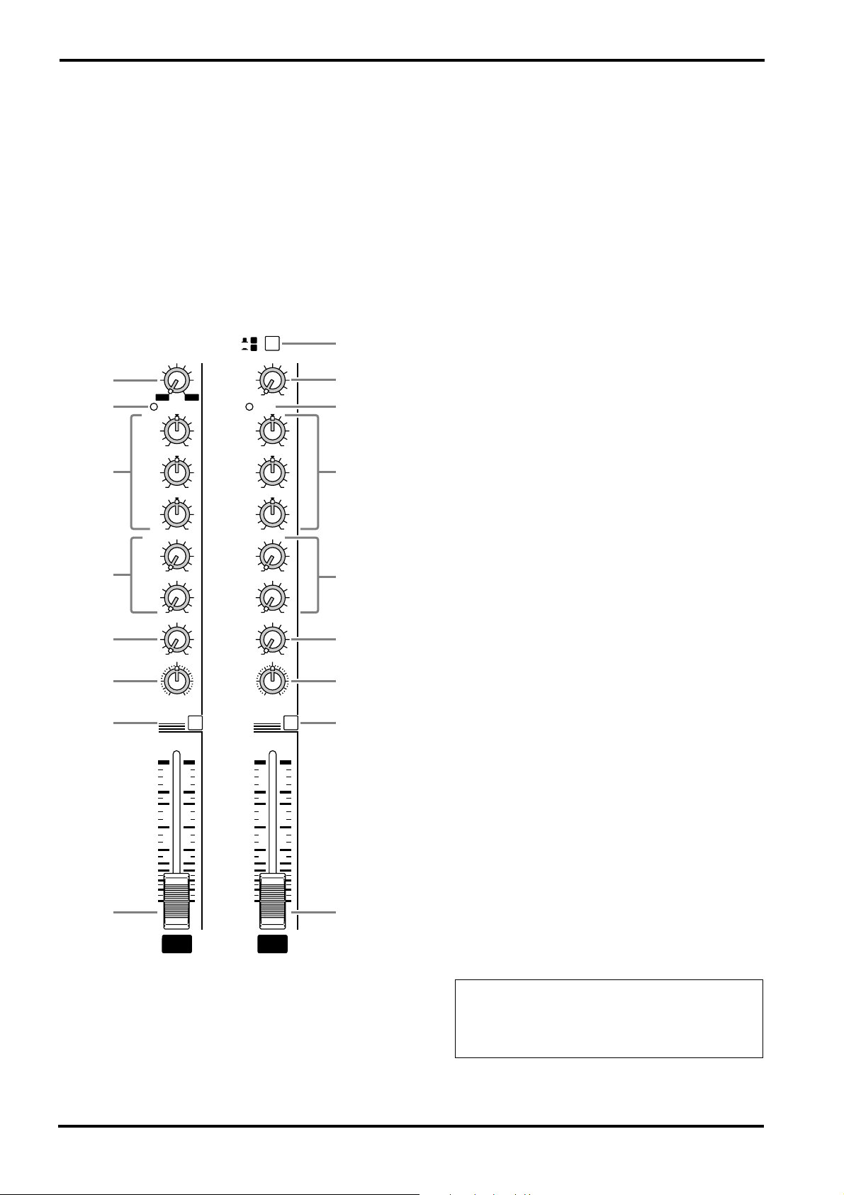
■
Channel control section
0
In this section, you can adjust equalization (frequency response), volume level, effect and monitor output levels for the input signal of each
channel.
1
3
4
5
6
7
9
GAIN
–34+10
–16
–60
PEAK PEAK
HIGH
MID
LOW
MONI 1
MONI 2
EFFECT
PAN
+15–15
+15–15
+15–15
100
100
100
L
R
PFL
0
A
B
GAIN
HIGH
MID
LOW
MONI 1
MONI 2
EFFECT
BAL
0
–34+10
+15–15
+15–15
+15–15
100
100
100
L
R
PFL
2
1
3
4
5
6
8
9
2
A/B switch (Channels 9/10~11/12 only)
This switch selects channel 9/10~11/12 connectors.
When the switch is up, the signal will be input
from connectors A (phone jacks on the input/
output panel 3 ).
When the switch is pressed in, the signal will be
input from connectors B (phono jacks on the
input/output panel 3 ).
3
PEAK indicator
The indicator will light 3 dB before clipping,
warning that clipping level is near.
4
Equalizer controls (HIGH, MID, LOW)
This is a 3-band equalizer that adjusts the high
frequency range, mid frequency range, and low
frequency range of each channel. Response is flat
when the knobs are in the “
▼
” position. Rotating
it toward the right will boost the corresponding
frequency band, and rotating it toward the left
will cut it.
The base frequency (or center frequency), range
of boost or cut, and equalizer type of each band
are as follows:
HIGH: 10kHz,
MID: 2.5kHz,
LOW: 100Hz,
±
15 dB, shelving type
±
15 dB, peaking type
±
15 dB, shelving type
5
10
15
20
25
30
40
50
∞
5
10
15
20
25
30
40
50
∞
0
1
1
GAIN control
Use this knob to adjust the sensitivity according
to the input signal level, so that the input level is
appropriate.
For the best balance of S/N ratio and dynamic
range, adjust this knob so that the peak indicator
lights occasionally.
EMX2000—Owner’s Manual
9/10
0
5
Monitor 1/2 controls (MONI 1/2)
For each channel, this controls the amount of signal that is sent to the MONITOR 1/2 buses.
The signal of the MONITOR 1 bus is sent to the
MONI 1 jack (input/output panel 9 ). If the
power amp select switch V is in the MONI 1MONO position, the signal is also sent to the
speakers connected to the SPEAKERS L1/2 jacks.
The signal of the MONITOR 2 bus is sent to the
MONI 2 jack (input/output panel 9 ).
Note: The signal sent to the MONITOR 1/2
buses does not pass through the channel fader
(pre-fader send). This means that it will not
be affected by the setting of the channel fader.
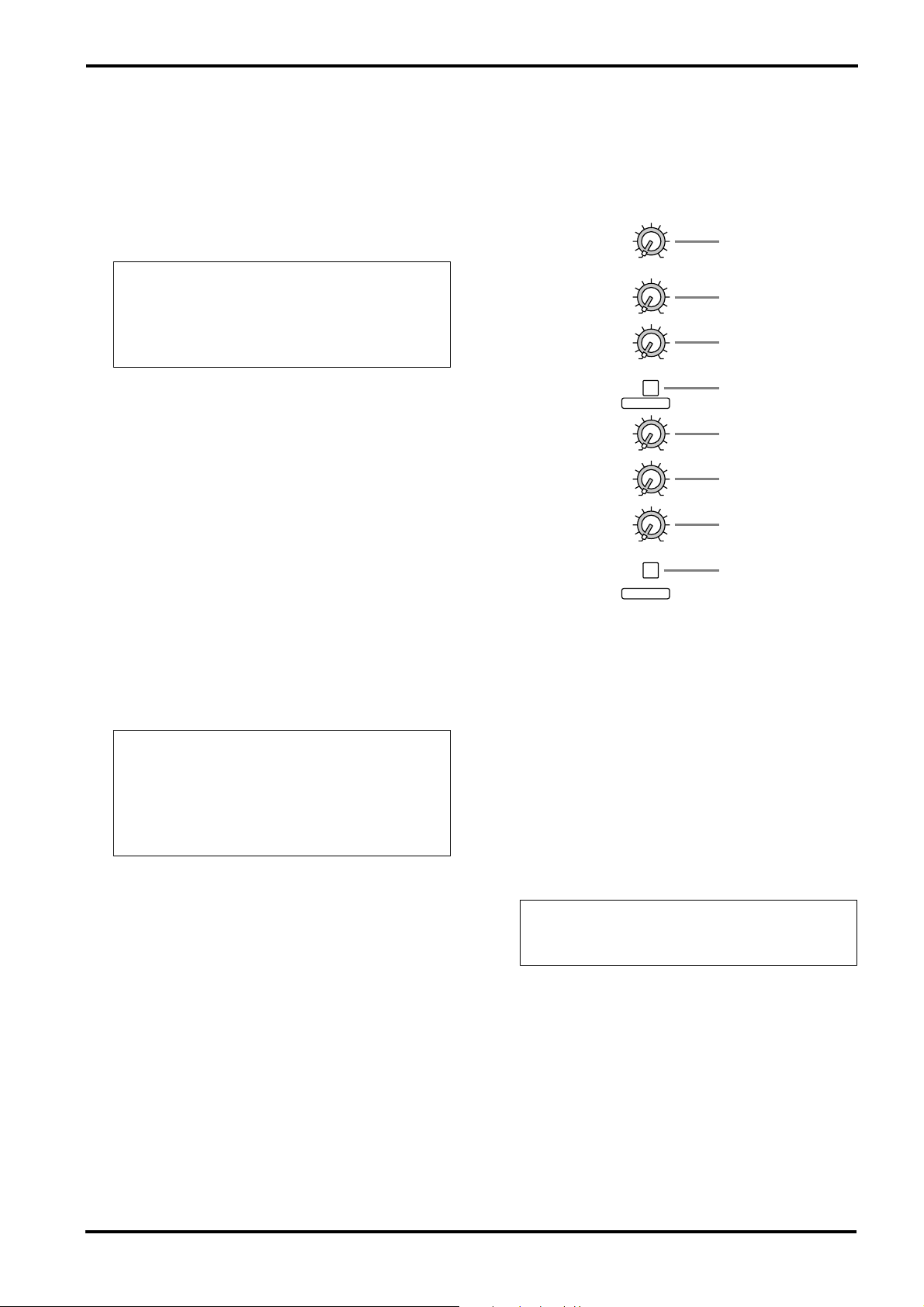
Effect control (EFFECT)
6
For each channel, this controls the amount of signal that is sent to the EFFECT bus.
The signal of the EFFECT bus is sent to the
EFFECT jack (input/output panel A). It is also
sent to the built-in effect when the ON switch P
in the EFFECT section is turned on.
Note: The amount of signal that is sent to the
EFFECT bus from each channel will be affected not only by the setting of the EFFECT control, but also by the setting of the channel fader
(post-fader send).
B ).
0
5
■
Stereo sub input section
In this section, you can adjust the input level of
external equipment connected to the ST SUB 1/2
jacks on the input/output panel.
MONI 1
100
MONI 2
100
ST
100
A
B
C
PAN (panpot) control (Channels 1~8)
7
The PAN knobs set the stereo position of the signal that is sent to the STEREO bus.
BAL (balance) control (Channels 9/10~
8
11/12)
The BAL knobs set the balance between the left
and right channels, and assign the signals
received at inputs 9/10~11/12 to the STEREO
bus.
9
PFL (pre-fader listen) switch
When the PFL switch is turned on, the signal of
the corresponding channel at the point after the
equalization but before the channel fader is sent
to the PHONES/C-R OUT jack (input/output
panel B ). This is useful when you wish to listen
to a particular channel through the headphones.
Note: You can monitor the signal through the
headphones even if the fader of the corresponding channel is set to the lowest level. The
switch operation does not affect the signal sent
to the STEREO bus, MONITOR 1/2 buses, or
the EFFECT bus.
0
Channel fader
This controls the output level of the input channel signal.
PFL
ST SUB 1
MONI 1
D
A
MONI 2
100
B
ST
100
C
100
PFL
ST SUB 2
A
MONI 1 (monitor 1) control
The MONI 1 knob adjusts the amount of the signal sent from the ST SUB 1 and 2 jacks (input/
output panel 4 ) to the MONITOR 1 bus.
B
MONI 2 (monitor 2) control
The MONI 2 knob adjusts the amount of the signal sent from the ST SUB 1 and 2 jacks to the
MONITOR 2 bus.
C
ST (stereo) control
The ST knob adjusts the amount of stereo signal
sent from the ST SUB 1 and 2 jacks to the STEREO bus.
Note: The ST control setting does not affect
the level of the signal sent to the MONITOR
1/2 buses (pre-fader send).
D
PFL (pre-fader listen) switch
D
When this switch is turned on, the signal at the
point before the ST control knob C is sent to the
PHONES/C-R OUT jack (input/output panel
EMX2000—Owner’s Manual
6
■
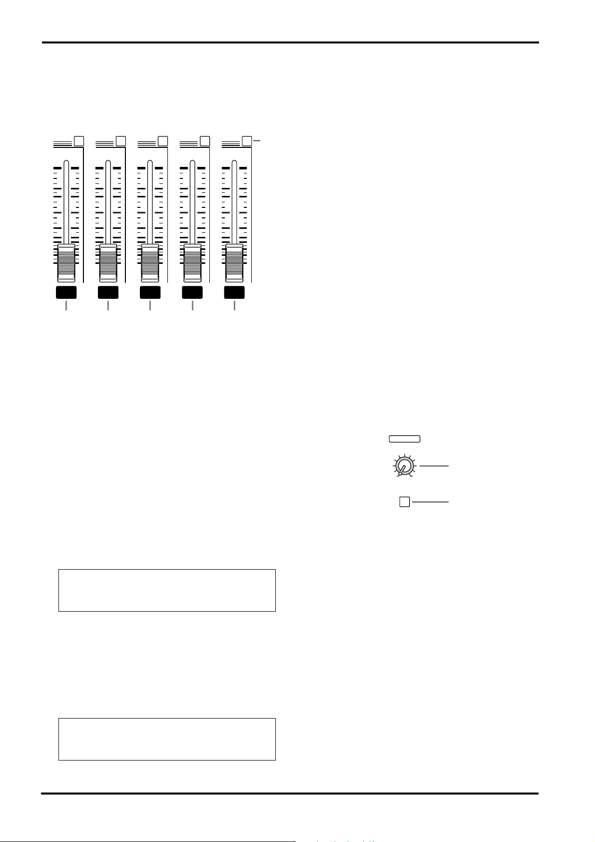
Master control section
In this section, you can adjust the final level of
the outputs.
AFL AFLAFLAFLAFL
0
5
10
15
20
25
30
40
50
∞
MONI 1 MONOST 1EFFECTMONI 2
0
5
10
15
20
25
30
40
50
∞
0
5
10
15
20
25
30
40
50
∞
0
5
10
15
20
25
30
40
50
∞
E F G H I
0
5
10
15
20
25
30
40
50
∞
J
9
MONO (monaural) fader
I
The MONO fader adjusts the final level of the
monaural signal output from the STEREO bus to
the MONO jack (input/output panel 0 ).
If the Power amp select switch V is set to
MONI 1-MONO, this fader also adjusts the level
of the signal sent from the SPEAKERS R 1/2 jacks
to the speakers.
If the Power amp select switch V is set to MONO
BRIDGE, this fader adjusts the level of the signal
sent from the SPEAKERS BRIDGE jack to the
speaker.
AFL (after fader listen)
J
When this switch is on, the output signal that
passes through the corresponding fader is sent to
the PHONES/C-R OUT jack (input/output panel
). Use these switches when you wish to monitor a particular output signal through the headphones.
8
B
MONI 1 (monitor 1) fader
E
The MONI 1 fader adjusts the final level of the
signal sent from the MONITOR 1 bus to the
MONI 1 jack (input/output panel
). If the
Power amp select switch V is set to MONI 1MONO, using this fader enables you to adjust the
level of the signal sent from the SPEAKER L 1/2
jacks to the speakers.
F
MONI 2 (monitor 2) fader
The MONI 2 fader adjusts the final level of the
signal output from the MONITOR 2 bus to the
MONI 2 jack (input/output panel 9 ).
G
EFFECT fader
The EFFECT fader adjusts the final level of the
signal output from the EFFECT bus to the
EFFECT jack (input/output panel A ).
Note: The setting of this fader does not affect
the level of the signal sent from the EFFECT
bus to the built-in effect.
ST 1 (stereo 1) fader
H
The ST 1 fader adjusts the final level of the signal
sent from the STEREO bus to the ST 1 jacks
(input/output panel
). If the Power amp select
switch V is set to ST L-ST R, this fader also
adjusts the level of the signal sent to the SPEAKERS jacks (rear panel 1 ).
■
Tape in section
In this section, you can adjust the input level of a
cassette deck or a CD player that is connected to
the TAPE jacks (input/output panel 5 ).
TAPE IN
ST
K
100
PFL
K
ST (stereo) control
This knob adjusts the level of the signal sent from
the TAPE jacks to the STEREO bus.
L
PFL (pre-fader listen) switch
When this switch is on, the signal input from the
TAPE jacks is routed at the point before the ST
control to the PHONES/C-R OUT jack (input/
output panel B).
L
Note: The setting of this fader does not affect
the signal output from the STEREO bus to the
ST 2 jacks.
EMX2000—Owner’s Manual
 Loading...