

Page 1
DIGITAL MULTITRACK RECORDER
Owner’s Manual
ABS H
OVER
0
–dB
00 00 00 00
2
6
YAMAHA D24
12
20
30
42
LOCK
60
READY
R
L
8
7
4
1
0/-
RECORD
READY
SOLO/
SELECT
OVER
0
–dB
2
6
1012
1420
1830
20
42
2660
READY
7654321
ALL
AUTO
PEAK
HOLD
INPUT
INPUT
FORMAT CHASE
MONITOR SELECT
Keep This Manual For Future Reference.
INT
WC
24
BITFSTC
8
5
2
MSF
48K
MASTER
PROJECT
9
SELECT
LOC MEM
6
RECALL
LOC MEM
3
STORE
LOCATEENTERCANCEL
TIME DISPLAY
CAPTURE ABS/REL
VARI
UTILITY
SPEED
V. TR ACK
EDIT
SELECT
REMAIN
SETUP
UNDO/
REDO
JOG ON
JOG/DATA SHUTTLE/
CURSOR
PROJECT SEARCH
RTN TO
ROLL
ZERO
BACK
REW FF
DIGITAL MULTITRACK RECORDER
LAST REC
OUT
IN
A
B
STOP PLAY REC
SET
REPEAT
POWER
ON
OFF
AUTO
PUNCH
REHE
BA
010
PHONES
LEVEL
PHONES
E
Page 2
FCC INFORMATION (U.S.A.)
1. IMPORTANT NOTICE: DO NOT MODIFY THIS UNIT! This product, when installed as indicated in the instructions contained in this manual, meets FCC
requirements. Modifications not expressly approved by Yamaha may void your authority, granted by the FCC, to use the product.
2. IMPORTANT: When connecting this product to accessories and/or another product use only high quality shielded cables. Cable/s supplied with this product MUST
be used. Follow all installation instructions. Failure to follow instructions could void your FCC authorization to use this product in the USA.
3. NOTE: This product has been tested and found to comply with the requirements listed in FCC Regulations, Part 15 for Class “B” digital devices. Compliance with
these requirements provides a reasonable level of assurance that your use of this product in a residential environment will not result in harmful interference with
other electronic devices. This equipment generates/uses radio frequencies and, if not installed and used according to the instructions found in the users manual, may
cause interference harmful to the operation of other electronic devices. Compliance with FCC regulations does not guarantee that interference will not occur in all
installations. If this product is found to be the source of interference, which can be determined by turning the unit “OFF” and “ON”, please try to eliminate the
problem by using one of the following measures: Relocate either this product or the device that is being affected by the interference. Utilize power outlets that are on
different branch (circuit breaker or fuse) circuits or install AC line filter/s. In the case of radio or TV interference, relocate/reorient the antenna. If the antenna lead-in
is 300 ohm ribbon lead, change the lead-in to coaxial type cable. If these corrective measures do not produce satisfactory results, please contact the local retailer
authorized to distribute this type of product. If you can not locate the appropriate retailer, please contact Yamaha Corporation of America, Electronic Service
Division, 6600 Orangethorpe Ave, Buena Park, CA 90620
The above statements apply ONLY to those products distributed by Yamaha Corporation of America or its subsidiaries.
WARNING: THIS APPARATUS MUST BE EARTHED
IMPORTANT
THE WIRES IN THIS MAINS LEAD ARE COLOURED IN
ACCORDANCE WITH THE FOLLOWING CODE:
GREEN-AND-YELLOW : EARTH
BLUE : NEUTRAL
BROWN : LIVE
As the colours of the wires in the mains lead of this apparatus may
not correspond with the coloured markings identifying the terminals in
your plug, proceed as follows:
The wire which is coloured GREEN and YELLOW must be
connected to the terminal in the plug which is marked by the letter E
or by the safety earth symbol or coloured GREEN and YELLOW.
The wire which is coloured BLUE must be connected to the terminal
which is marked with the letter N or coloured BLACK.
The wire which is coloured BROWN must be connected to the
terminal which is marked with the letter L or coloured RED.
* This applies only to products distributed by YAMAHA KEMBLE
MUSIC (U.K.) LTD.
ADVARSEL!
Lithiumbatteri—Eksplosionsfare ved fejlagtig
håndtering. Udskiftning må kun ske med batteri
af samme fabrikat og type. Levér det brugte
batteri tilbage til leverandoren.
VARNING
Explosionsfara vid felaktigt batteribyte. Använd
samma batterityp eller en ekvivalent typ som
rekommenderas av apparattillverkaren.
Kassera använt batteri enligt fabrikantens
instruktion.
VAROITUS
Paristo voi räjähtää, jos se on virheellisesti
asennettu. Vaihda paristo ainoastaan
laitevalmistajan suosittelemaan tyyppiin. Hävitä
käytetty paristo valmistajan ohjeiden
mukaisesti.
NEDERLAND THE NETHERLANDS
● Dit apparaat bevat een lithium batterij voor geheugen
back-up.
● Raadpleeg uw leverancier over de verwijdering van de
batterij op het moment dat u het apparaat ann het einde
van de levensduur afdankt of de volgende Yamaha Service
Afdeiing:
Yamaha Music Nederland Service Afdeiing
Kanaalweg 18-G, 3526 KL UTRECHT
Tel. 030-2828425
● Gooi de batterij niet weg, maar lever hem in als KCA.
● This apparatus contains a lithium battery for memory
back-up.
● For the removal of the battery at the moment of the
disposal at the end of the service life please consult your
retailer or Yamaha Service Center as follows:
Yamaha Music Nederland Service Center
Address: Kanaalweg 18-G, 3526 KL
UTRECHT
Tel: 030-2828425
● Do not throw away the battery. Instead, hand it in as small
chemical waste.
Page 3
Laser Diode Properties
* Material : AlGaInP
* Wavelength : 675–695 nm
* Emission Duration : Continuous
* Laser Output Power : Less than 44.6 µW
(Note)
Laser output is measured at a
distance of 20 cm from the object
lens on the optical pick-up head.
This unit is classified as a
CLASS 1 LASER PRODUCT
LUOKAN 1 LASERLAITE
KLASS 1 LASERAPPARAT
Class 1 laser product.
This label is located on the
exterior.
Klassmärkning för Finland.
DANGER
INVISIBLE LASER RADIATION WHEN OPEN.
AVOID DIRECT EXPOSURE TO BEAM.
DANGER
RADIATIONS INVISIBLES DU LASER EN CAS D' OUVERTURE.
EVITER TOUTE EXPOSITION DIRECTE AU FAISCEAU.
VORSICHT
LASERSTRAHLUNG. WENN ABDECKUNG GEÖFFNET
NICHT DEM STRAHL AUSSETZEN.
ADVARSEL
USYNLIG LASERSTRÅLING VED ÅBNING NÅR
SIKKERHEDSAFBRYDERE ER UDE AF FUNKTION.
UNDGÅ UDSAETTELSE FOR STRÅLING.
VARNING
OSYNLIG LASERSTRÅLNING NÄR
DENNA DEL ÄR ÖPPEND. STRÅLEN
ÄR FARLIG.
APL
• These labels are
located on the interior.
• Varningsanvisning för
laserstrålning. Placerad
i apparaten.
CAUTION
USE OF CONTROLS OR ADJUSTMENTS OR
PERFORMANCE OF PROCEDURES OTHER
THAN THOSE SPECIFIED HEREIN MAY RESULT
IN HAZARDOUS RADIATION EXPOSURE.
ADVARSEL
Usynlig laserstråling ved åbning. Undgå udsaettelse
for stråling.
VAROITUS
Laitteen käyttäminen muulla kuin tässä käyttöohjeesa
mainitulla tavalla saattaa altistaa käyttäjän
turvallisuusluokan 1 ylittävälle näkymättömälle
lasersäteilylle.
VARNING
Om apparaten används på annat sätt än i denna
bruksanvisning specificerats, kan användaren utsättas
för osynlig laserstrålning, som överskrider gränsen för
laserklass 1.
Page 4

i
Important Information
Read the Following Before Operating the D24
Warnings
• Do not subject the D24 to extreme temperatures, humidity, direct sunlight, or dust,
which could be a potential fire or electrical shock hazard.
• Connect the D24 power cord to an AC outlet of the type stated in this
or as indicated on the D24. Failure to do so is a fire and electrical shock hazard.
• Do not plug several devices into the same AC outlet. This may overload the AC outlet,
and could be a fire or electrical shock hazard. It may also affect the performance of some
devices.
• Do not place heavy objects on the power cord. A damaged power cord is a potential fire
and electrical shock hazard.
• If the power cord is damaged (e.g., cut or a bare wire is exposed), ask your dealer for a
replacement. Using the D24 with a damaged power cord is a fire and shock hazard.
• Hold the power cord plug when disconnecting from an AC outlet. Never pull the cord.
A power cord damaged through pulling is a potential fire and electrical shock hazard.
Owner’s Manual
• Do not place small metal objects on top of the D24. Metal objects falling inside the D24
is a fire and electrical shock hazard.
• Do not block the D24 ventilation slots. The D24 has ventilation slots at the side and a
cooling fan at the rear to keep the internal components cool. Blocking the ventilation
slots or obstructing the fan’s airflow is a potential fire hazard.
• Do not attempt to modify the D24. This is a potential fire and electrical shock hazard.
• The D24 operating temperature is between 5˚C and 35˚C (41˚F and 95˚F).
Cautions
• Allow enough free space around the unit for normal ventilation. This should be: 10 cm
behind and 20 cm above.
These distances should also be adopted when rack-mounting the unit. For normal ventilation during use, remove the rear of the rack or open a ventilation hole.
If the airflow is not adequate, the unit will heat up inside and may cause a fire.
• Turn off audio devices when connecting them to the D24, and use only the cables specified in the relevant owner’s manuals.
• If you notice any abnormality—such as smoke, odor, or noise—turn off the D24 immediately. Remove the power cord from the AC outlet. Confirm that the abnormality is no
longer present. Using the D24 in this condition is a potential fire and shock hazard.
Consult your dealer for repair.
• If a foreign object or water gets inside the D24, turn it off immediately. Remove the
power cord from the AC outlet. Using the D24 in this condition is a potential fire and
electrical shock hazard. Consult your dealer for repair.
• If you plan not to use the D24 for a long period of time, remove the power cord from
the AC outlet. Leaving the D24 connected is a potential fire hazard.
• Do not use benzene, thinner, cleaning detergent, or a chemical cloth to clean the D24.
Use only a soft, dry cloth.
D24—Owner’s Manual
Page 5

ii
MO Disks
• Use only MO disks of the type specified in this manual.
• Store MO disks in a place free from extreme temperatures, humidity, dust, and dirt.
• Do not slide open the MO disk shutter, and never touch the actual disk.
• If an MO disk is stored in a cold place (e.g., overnight in a car), and then moved to a
warmer environment, condensation may form on the disk. In this case, the disk should
be left to acclimatize for about 30 minutes before use.
Interference
The D24 uses high-frequency digital circuits that may cause interference on radio and
television equipment located nearby. If interference is a problem, relocate the affected
equipment.
D24 Exclusion of Certain Responsibility
Manufacturer, importer, or dealer shall not be liable for any incidental damages including personal injury or any other damages caused by improper use or operation of the
D24.
Package Contents
The D24 package should contain the following items. Contact your Yamaha dealer if
you are missing an item.
• D24 Digital Multitrack Recorder
• This manual
•Power cord
• MO disk
• Disk eject tool
Trademarks
ADAT MultiChannel Optical Digital Interface is a trademark and ADAT and Alesis are
registered trademarks of Alesis Corporation. Apple and Macintosh are registered trademarks of Apple Computer, Inc. Digidesign and OMF are registered trademarks and
Sound Designer II is a trademark of Avid Technology, Inc. Tascam Digital Interface is a
trademark and Tascam and Teac are registered trademarks of Teac Corporation.
MS-DOS is a registered trademark and Windows is a trademark of Microsoft Corporation. Yamaha is a trademark of Yamaha Corporation. All other trademarks are the property of their respective holders and are hereby acknowledged.
Copyright
No part of the D24 software or this Owner’s Manual may be reproduced or distributed
in any form or by any means without the prior written authorization of Yamaha Corporation.
© 1999 Yamaha Corporation. All rights reserved.
D24—Owner’s Manual
Page 6

Contents
Contents
1 Welcome to the D24 . . . . . . . . . . . . . . . . . . . . . . . . 1
Welcome to the D24 . . . . . . . . . . . . . . . . . . . . . . . . . . . . . . . . . . . . . . . . . 2
About this Manual . . . . . . . . . . . . . . . . . . . . . . . . . . . . . . . . . . . . . . . . . . . 3
Installing the D24 . . . . . . . . . . . . . . . . . . . . . . . . . . . . . . . . . . . . . . . . . . . . 3
D24 Features . . . . . . . . . . . . . . . . . . . . . . . . . . . . . . . . . . . . . . . . . . . . . . . . 4
Choosing MO Disks . . . . . . . . . . . . . . . . . . . . . . . . . . . . . . . . . . . . . . . . . . 6
2 Touring the D24 . . . . . . . . . . . . . . . . . . . . . . . . . . . 9
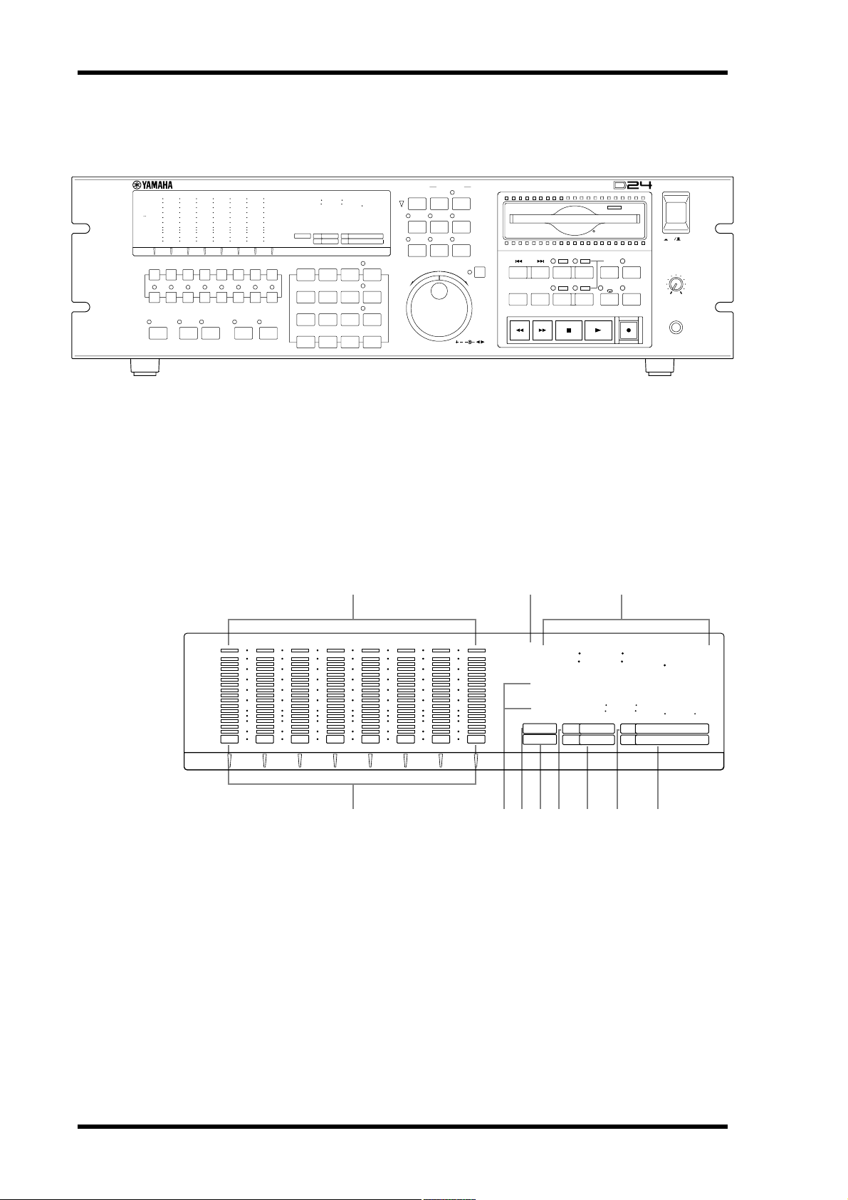
Front Panel . . . . . . . . . . . . . . . . . . . . . . . . . . . . . . . . . . . . . . . . . . . . . . . . 10
Display . . . . . . . . . . . . . . . . . . . . . . . . . . . . . . . . . . . . . . . . . . . . . . . . . . . 10
Transport Controls . . . . . . . . . . . . . . . . . . . . . . . . . . . . . . . . . . . . . . . . . 12
Power Switch & Phones . . . . . . . . . . . . . . . . . . . . . . . . . . . . . . . . . . . . . . 14
Jog/Data & Shuttle/Cursor Controls . . . . . . . . . . . . . . . . . . . . . . . . . . . 15
Function Buttons . . . . . . . . . . . . . . . . . . . . . . . . . . . . . . . . . . . . . . . . . . . 16
Peak, Monitor, Format & Chase Buttons . . . . . . . . . . . . . . . . . . . . . . . 17
Keypad . . . . . . . . . . . . . . . . . . . . . . . . . . . . . . . . . . . . . . . . . . . . . . . . . . . 18
Track Buttons . . . . . . . . . . . . . . . . . . . . . . . . . . . . . . . . . . . . . . . . . . . . . . 19
Rear Panel . . . . . . . . . . . . . . . . . . . . . . . . . . . . . . . . . . . . . . . . . . . . . . . . . 20
iii
3 The Basics . . . . . . . . . . . . . . . . . . . . . . . . . . . . . . . 23
Connecting the Power Cord . . . . . . . . . . . . . . . . . . . . . . . . . . . . . . . . . . 24
Turning On & Off the D24 . . . . . . . . . . . . . . . . . . . . . . . . . . . . . . . . . . . 24
Write Protecting Disks . . . . . . . . . . . . . . . . . . . . . . . . . . . . . . . . . . . . . . 24
Inserting & Ejecting Disks . . . . . . . . . . . . . . . . . . . . . . . . . . . . . . . . . . . . 25
Formatting MO Disks . . . . . . . . . . . . . . . . . . . . . . . . . . . . . . . . . . . . . . . 26
Transport Operation Table . . . . . . . . . . . . . . . . . . . . . . . . . . . . . . . . . . . 27
Indicator Status Tables . . . . . . . . . . . . . . . . . . . . . . . . . . . . . . . . . . . . . . 28
4 Recording . . . . . . . . . . . . . . . . . . . . . . . . . . . . . . . . 29
About Projects . . . . . . . . . . . . . . . . . . . . . . . . . . . . . . . . . . . . . . . . . . . . . 30
Preparing to Record . . . . . . . . . . . . . . . . . . . . . . . . . . . . . . . . . . . . . . . . . 31
Setting the Recording Resolution . . . . . . . . . . . . . . . . . . . . . . . . . . . . . . 32
Recording . . . . . . . . . . . . . . . . . . . . . . . . . . . . . . . . . . . . . . . . . . . . . . . . . 33
Conserving Disk Space . . . . . . . . . . . . . . . . . . . . . . . . . . . . . . . . . . . . . . 35
Undoing a Recording or Edit . . . . . . . . . . . . . . . . . . . . . . . . . . . . . . . . . 35
Rehearsing . . . . . . . . . . . . . . . . . . . . . . . . . . . . . . . . . . . . . . . . . . . . . . . . 36
Extending the Top of a Project . . . . . . . . . . . . . . . . . . . . . . . . . . . . . . . . 37
Checking the Time Remaining . . . . . . . . . . . . . . . . . . . . . . . . . . . . . . . . 38
Metering . . . . . . . . . . . . . . . . . . . . . . . . . . . . . . . . . . . . . . . . . . . . . . . . . . 39
Using Normal & Fine Metering . . . . . . . . . . . . . . . . . . . . . . . . . . . . . . . 40
Using Peak Hold . . . . . . . . . . . . . . . . . . . . . . . . . . . . . . . . . . . . . . . . . . . 41
Monitoring . . . . . . . . . . . . . . . . . . . . . . . . . . . . . . . . . . . . . . . . . . . . . . . . 42
5 General Operation . . . . . . . . . . . . . . . . . . . . . . . . . 45
Using Playback . . . . . . . . . . . . . . . . . . . . . . . . . . . . . . . . . . . . . . . . . . . . . 46
Using Fast Forward & Rewind . . . . . . . . . . . . . . . . . . . . . . . . . . . . . . . . 46
A–B Repeat Playback . . . . . . . . . . . . . . . . . . . . . . . . . . . . . . . . . . . . . . . . 47
D24—Owner’s Manual
Page 7

iv
Contents
Soloing Tracks . . . . . . . . . . . . . . . . . . . . . . . . . . . . . . . . . . . . . . . . . . . . . 48
Selecting the Solo Outputs . . . . . . . . . . . . . . . . . . . . . . . . . . . . . . . . . . . 48
Using Absolute & Relative Zero . . . . . . . . . . . . . . . . . . . . . . . . . . . . . . . 49
Using Roll-back . . . . . . . . . . . . . . . . . . . . . . . . . . . . . . . . . . . . . . . . . . . . 50
Setting the Roll-back Time . . . . . . . . . . . . . . . . . . . . . . . . . . . . . . . . . . . 50
Using Virtual Tracks . . . . . . . . . . . . . . . . . . . . . . . . . . . . . . . . . . . . . . . . 51
Shuttling . . . . . . . . . . . . . . . . . . . . . . . . . . . . . . . . . . . . . . . . . . . . . . . . . . 52
Nudging the Current Position . . . . . . . . . . . . . . . . . . . . . . . . . . . . . . . . 53
Setting the Nudge Time . . . . . . . . . . . . . . . . . . . . . . . . . . . . . . . . . . . . . . 54
Using Varispeed . . . . . . . . . . . . . . . . . . . . . . . . . . . . . . . . . . . . . . . . . . . . 55
6 Quick Locate . . . . . . . . . . . . . . . . . . . . . . . . . . . . . . 57
Searching for Projects . . . . . . . . . . . . . . . . . . . . . . . . . . . . . . . . . . . . . . . 58
Project Search Confirmation . . . . . . . . . . . . . . . . . . . . . . . . . . . . . . . . . 58
Selecting Projects Directly . . . . . . . . . . . . . . . . . . . . . . . . . . . . . . . . . . . . 59
Returning to Zero . . . . . . . . . . . . . . . . . . . . . . . . . . . . . . . . . . . . . . . . . . 60
Using the A & B Points . . . . . . . . . . . . . . . . . . . . . . . . . . . . . . . . . . . . . . 61
Locating the LAST REC IN & OUT Points . . . . . . . . . . . . . . . . . . . . . . 62
Locating Positions Directly . . . . . . . . . . . . . . . . . . . . . . . . . . . . . . . . . . . 63
Storing Locate Points . . . . . . . . . . . . . . . . . . . . . . . . . . . . . . . . . . . . . . . . 64
Storing Locate Points Automatically . . . . . . . . . . . . . . . . . . . . . . . . . . . 65
Recalling Locate Points . . . . . . . . . . . . . . . . . . . . . . . . . . . . . . . . . . . . . . 66
7 Punch In/Out Recording . . . . . . . . . . . . . . . . . . . . 67
About Punch In/Out Recording . . . . . . . . . . . . . . . . . . . . . . . . . . . . . . . 68
Manual Punch In/Out Rehearsal . . . . . . . . . . . . . . . . . . . . . . . . . . . . . . 69
Manual Punch In/Out Recording . . . . . . . . . . . . . . . . . . . . . . . . . . . . . . 70
Setting the LAST REC IN & OUT Points . . . . . . . . . . . . . . . . . . . . . . . . 71
Auto Punch In/Out Rehearsal . . . . . . . . . . . . . . . . . . . . . . . . . . . . . . . . 72
Auto Punch In/Out Recording . . . . . . . . . . . . . . . . . . . . . . . . . . . . . . . . 73
Setting the Pre-roll Time . . . . . . . . . . . . . . . . . . . . . . . . . . . . . . . . . . . . . 76
Setting the Post-roll Time . . . . . . . . . . . . . . . . . . . . . . . . . . . . . . . . . . . . 76
8 Editing Projects . . . . . . . . . . . . . . . . . . . . . . . . . . . . 77
Copying Projects . . . . . . . . . . . . . . . . . . . . . . . . . . . . . . . . . . . . . . . . . . . 78
Erasing Projects . . . . . . . . . . . . . . . . . . . . . . . . . . . . . . . . . . . . . . . . . . . . 79
Deleting Projects . . . . . . . . . . . . . . . . . . . . . . . . . . . . . . . . . . . . . . . . . . . 80
Titling Projects . . . . . . . . . . . . . . . . . . . . . . . . . . . . . . . . . . . . . . . . . . . . . 81
Protecting Projects . . . . . . . . . . . . . . . . . . . . . . . . . . . . . . . . . . . . . . . . . . 82
Modifying a Project’s Start Time . . . . . . . . . . . . . . . . . . . . . . . . . . . . . . 83
9 Editing Tracks . . . . . . . . . . . . . . . . . . . . . . . . . . . . . 85
Copying Tracks . . . . . . . . . . . . . . . . . . . . . . . . . . . . . . . . . . . . . . . . . . . . 86
Moving Tracks . . . . . . . . . . . . . . . . . . . . . . . . . . . . . . . . . . . . . . . . . . . . . 88
Erasing Tracks . . . . . . . . . . . . . . . . . . . . . . . . . . . . . . . . . . . . . . . . . . . . . 90
Swapping Tracks . . . . . . . . . . . . . . . . . . . . . . . . . . . . . . . . . . . . . . . . . . . 91
Slipping Tracks . . . . . . . . . . . . . . . . . . . . . . . . . . . . . . . . . . . . . . . . . . . . . 93
10 Editing Parts . . . . . . . . . . . . . . . . . . . . . . . . . . . . . . 95
Copying Parts . . . . . . . . . . . . . . . . . . . . . . . . . . . . . . . . . . . . . . . . . . . . . . 96
Moving Parts . . . . . . . . . . . . . . . . . . . . . . . . . . . . . . . . . . . . . . . . . . . . . . 99
D24—Owner’s Manual
Page 8

Contents
Deleting Parts . . . . . . . . . . . . . . . . . . . . . . . . . . . . . . . . . . . . . . . . . . . . . . 102
Erasing Parts . . . . . . . . . . . . . . . . . . . . . . . . . . . . . . . . . . . . . . . . . . . . . . . 104
Inserting Parts . . . . . . . . . . . . . . . . . . . . . . . . . . . . . . . . . . . . . . . . . . . . . 106
Insert Copying Parts . . . . . . . . . . . . . . . . . . . . . . . . . . . . . . . . . . . . . . . . 108
Time Compression . . . . . . . . . . . . . . . . . . . . . . . . . . . . . . . . . . . . . . . . . 111
Pitch Change . . . . . . . . . . . . . . . . . . . . . . . . . . . . . . . . . . . . . . . . . . . . . . 116
11 Wordclocks . . . . . . . . . . . . . . . . . . . . . . . . . . . . . . 121
Wordclocks & the D24 . . . . . . . . . . . . . . . . . . . . . . . . . . . . . . . . . . . . . . 122
Wordclock Connections . . . . . . . . . . . . . . . . . . . . . . . . . . . . . . . . . . . . . 123
Dual AES/EBU Mode . . . . . . . . . . . . . . . . . . . . . . . . . . . . . . . . . . . . . . . 123
Selecting a Wordclock Source . . . . . . . . . . . . . . . . . . . . . . . . . . . . . . . . . 124
Wordclock System Examples . . . . . . . . . . . . . . . . . . . . . . . . . . . . . . . . . 126
Terminating BNC Wordclock Distribution . . . . . . . . . . . . . . . . . . . . . 131
12 Timecode . . . . . . . . . . . . . . . . . . . . . . . . . . . . . . . . 133
Timecode & the D24 . . . . . . . . . . . . . . . . . . . . . . . . . . . . . . . . . . . . . . . . 134
Timecode Connections . . . . . . . . . . . . . . . . . . . . . . . . . . . . . . . . . . . . . . 134
Selecting a Timecode Source . . . . . . . . . . . . . . . . . . . . . . . . . . . . . . . . . . 135
Setting the Timecode Frame Rate . . . . . . . . . . . . . . . . . . . . . . . . . . . . . . 136
Setting a Timecode Offset . . . . . . . . . . . . . . . . . . . . . . . . . . . . . . . . . . . . 137
Chasing External Timecode . . . . . . . . . . . . . . . . . . . . . . . . . . . . . . . . . . 138
Setting the Chase Speed . . . . . . . . . . . . . . . . . . . . . . . . . . . . . . . . . . . . . . 139
Transmitting MTC . . . . . . . . . . . . . . . . . . . . . . . . . . . . . . . . . . . . . . . . . . 139
Timecode Hookup Examples . . . . . . . . . . . . . . . . . . . . . . . . . . . . . . . . . 140
v
13 Multiple D24s & Video Sync . . . . . . . . . . . . . . . . . 143
Multiple D24s . . . . . . . . . . . . . . . . . . . . . . . . . . . . . . . . . . . . . . . . . . . . . . 144
Expanding the Number of Tracks . . . . . . . . . . . . . . . . . . . . . . . . . . . . . 145
Extending the Recording Time . . . . . . . . . . . . . . . . . . . . . . . . . . . . . . . . 147
Setting the Serial Point . . . . . . . . . . . . . . . . . . . . . . . . . . . . . . . . . . . . . . 149
Using Video Sync . . . . . . . . . . . . . . . . . . . . . . . . . . . . . . . . . . . . . . . . . . . 149
Terminating BNC Video Sync Distribution . . . . . . . . . . . . . . . . . . . . . 150
Connecting a Video Editor . . . . . . . . . . . . . . . . . . . . . . . . . . . . . . . . . . . 151
Video Hookup Example . . . . . . . . . . . . . . . . . . . . . . . . . . . . . . . . . . . . . 151
14 SCSI & External Disk Drives . . . . . . . . . . . . . . . . . . 153
SCSI & the D24 . . . . . . . . . . . . . . . . . . . . . . . . . . . . . . . . . . . . . . . . . . . . 154
Using External Disk Drives . . . . . . . . . . . . . . . . . . . . . . . . . . . . . . . . . . . 154
Certified Disk Drives . . . . . . . . . . . . . . . . . . . . . . . . . . . . . . . . . . . . . . . . 155
Available Recording Time . . . . . . . . . . . . . . . . . . . . . . . . . . . . . . . . . . . . 155
Connecting Disk Drives . . . . . . . . . . . . . . . . . . . . . . . . . . . . . . . . . . . . . 156
Assigning SCSI IDs . . . . . . . . . . . . . . . . . . . . . . . . . . . . . . . . . . . . . . . . . 156
Terminating the SCSI Bus . . . . . . . . . . . . . . . . . . . . . . . . . . . . . . . . . . . . 157
Formatting External Disk Drives . . . . . . . . . . . . . . . . . . . . . . . . . . . . . . 158
Selecting the Work Disk . . . . . . . . . . . . . . . . . . . . . . . . . . . . . . . . . . . . . 161
Duplicating MO Disks . . . . . . . . . . . . . . . . . . . . . . . . . . . . . . . . . . . . . . . 162
Copying Projects Between Disk Drives . . . . . . . . . . . . . . . . . . . . . . . . . 164
Mounting D24 Disks on a Personal Computer . . . . . . . . . . . . . . . . . . . 165
Connecting the D24 to a Personal Computer . . . . . . . . . . . . . . . . . . . . 166
D24—Owner’s Manual
Page 9

vi
Contents
15 Other Functions . . . . . . . . . . . . . . . . . . . . . . . . . . 169
Setting the Peak Hold Mode . . . . . . . . . . . . . . . . . . . . . . . . . . . . . . . . . . 170
Setting the Fade In/Out Time . . . . . . . . . . . . . . . . . . . . . . . . . . . . . . . . . 170
Setting the Display Brightness . . . . . . . . . . . . . . . . . . . . . . . . . . . . . . . . 171
Setting the Remote ID . . . . . . . . . . . . . . . . . . . . . . . . . . . . . . . . . . . . . . . 171
Recovering Disk Space . . . . . . . . . . . . . . . . . . . . . . . . . . . . . . . . . . . . . . . 172
Physical Formatting for MO Disks . . . . . . . . . . . . . . . . . . . . . . . . . . . . . 173
Ejecting Troublesome Disks (emergency use) . . . . . . . . . . . . . . . . . . . 174
Initializing the D24 . . . . . . . . . . . . . . . . . . . . . . . . . . . . . . . . . . . . . . . . . 175
Checking the Version Number . . . . . . . . . . . . . . . . . . . . . . . . . . . . . . . . 175
Updating the System Software . . . . . . . . . . . . . . . . . . . . . . . . . . . . . . . . 175
16 MIDI . . . . . . . . . . . . . . . . . . . . . . . . . . . . . . . . . . . 177
MIDI & the D24 . . . . . . . . . . . . . . . . . . . . . . . . . . . . . . . . . . . . . . . . . . . . 178
MIDI Ports . . . . . . . . . . . . . . . . . . . . . . . . . . . . . . . . . . . . . . . . . . . . . . . . 178
Using MMC (MIDI Machine Control) . . . . . . . . . . . . . . . . . . . . . . . . . 178
17 Digital Audio I/O . . . . . . . . . . . . . . . . . . . . . . . . . 181
About mini YGDAI Cards . . . . . . . . . . . . . . . . . . . . . . . . . . . . . . . . . . . . 182
Card Specifications . . . . . . . . . . . . . . . . . . . . . . . . . . . . . . . . . . . . . . . . . 183
Choosing Digital I/O Cards . . . . . . . . . . . . . . . . . . . . . . . . . . . . . . . . . . 183
Choosing D24 Slots . . . . . . . . . . . . . . . . . . . . . . . . . . . . . . . . . . . . . . . . . 184
Selecting Slot Inputs . . . . . . . . . . . . . . . . . . . . . . . . . . . . . . . . . . . . . . . . 184
Installing Cards . . . . . . . . . . . . . . . . . . . . . . . . . . . . . . . . . . . . . . . . . . . . 185
Using Dual AES/EBU Mode . . . . . . . . . . . . . . . . . . . . . . . . . . . . . . . . . . 186
Using the Coaxial Digital Input & Output . . . . . . . . . . . . . . . . . . . . . . 187
Assigning the Coaxial Input & Output . . . . . . . . . . . . . . . . . . . . . . . . . 188
Emphasis & the D24 . . . . . . . . . . . . . . . . . . . . . . . . . . . . . . . . . . . . . . . . 188
SCMS & the D24 . . . . . . . . . . . . . . . . . . . . . . . . . . . . . . . . . . . . . . . . . . . 188
Digital I/O & Wordlength . . . . . . . . . . . . . . . . . . . . . . . . . . . . . . . . . . . . 189
Troubleshooting . . . . . . . . . . . . . . . . . . . . . . . . . . . . . 191
Appendix . . . . . . . . . . . . . . . . . . . . . . . . . . . . . . . . . . 193
Setting the SCSI ID of the Internal MO Drive . . . . . . . . . . . . . . . . . . . 193
Error Messages . . . . . . . . . . . . . . . . . . . . . . . . . . . . . . . . . . . . . . . . . . . . . 194
Specifications . . . . . . . . . . . . . . . . . . . . . . . . . . . . . . . . . . . . . . . . . . . . . . 196
Connector Pin Assignments . . . . . . . . . . . . . . . . . . . . . . . . . . . . . . . . . . 199
D24 Dimensions . . . . . . . . . . . . . . . . . . . . . . . . . . . . . . . . . . . . . . . . . . . . 200
Glossary . . . . . . . . . . . . . . . . . . . . . . . . . . . . . . . . . . . 201
Index . . . . . . . . . . . . . . . . . . . . . . . . . . . . . . . . . . . . . . 205
MIDI Implementation Chart . . . . . . . . . . . . . . . . . . . . 211
D24—Owner’s Manual
Page 10

In this chapter...
Welcome to the D24
Welcome to the D24
1
1
Welcome to the D24 . . . . . . . . . . . . . . . . . . . . . . . . . . . . . . . . . . . . . . . . . . . . . . . . 2
About this Manual . . . . . . . . . . . . . . . . . . . . . . . . . . . . . . . . . . . . . . . . . . . . . . . . . 3
Installing the D24 . . . . . . . . . . . . . . . . . . . . . . . . . . . . . . . . . . . . . . . . . . . . . . . . . . 3
D24 Features . . . . . . . . . . . . . . . . . . . . . . . . . . . . . . . . . . . . . . . . . . . . . . . . . . . . . . 4
Choosing MO Disks . . . . . . . . . . . . . . . . . . . . . . . . . . . . . . . . . . . . . . . . . . . . . . . . 6
D24—Owner’s Manual
Page 11

2
Chapter 1—Welcome to the D24
Welcome to the D24
Thank you for choosing the Yamaha D24 Digital Multitrack Recorder.
The D24 uses standard 3.5-inch removable MO (Magneto Optical) disks for digital
audio recording and playback. By employing a removable media, backup downtime in
between sessions is eliminated. When one session is complete, simply insert a new disk
and begin recording right away. Random access capability provides instant access to up
to 99 projects per disk, 99 locate memories per project, all without unproductive
rewinding and fast forwarding. Audio data is not compressed, and superb sonic performance is achieved using 16-, 20-, or 24-bit recording resolutions and 44.1 kHz, 48 kHz,
88.2 kHz, or 96 kHz sampling rates, all of which can be set on a project-by-project basis.
Overwrite-type 640 MB MO disks offer 8-track simultaneous recording, with a 24-bit
recording resolution and 44.1 kHz or 48 kHz sampling rates, and 4-track simultaneous
recording at the higher sampling rates of 88.2 kHz or 96 kHz. A single 640 MB MO disk
provides a total recording time of 120 track minutes, or 30 minutes for 4 tracks, 15 minutes for 8 tracks. In addition to the eight main tracks, each track features up to eight virtual tracks, for a grand total of 64 tracks. Auto punch in/out recording, with multiple
take capability, allows you to choose the best from up to 99 takes. Both manual and auto
punch in/out recording can be rehearsed with automatic playback and input monitor
switching.
Video machine-like shuttle playback makes it easy to locate material, and the current
position can be nudged in sub-frame steps while listening to a small section of the surrounding material. Tracks can be soloed for individual track monitoring. Other features include ±6% varispeed, A-B repeat playback, and fast forward or rewind at 8x or
16x normal playback speed.
In addition to the 99 locate memories, the A, B, Last Rec In, and Last Rec Out points
offer additional ways locate specific positions quickly, repeatedly, and accurately. Other
quick locate functions include Project Search, Return to Zero, and Roll Back. Location
points can be specified with sub-frame accuracy.
Additional recording space can be made available, and projects backed up by connecting optional, external hard disk drives or removable media disk drives to the D24’s SCSI
port. The number of tracks available for simultaneous recording and playback can be
expanded in multiples of eight by combining up to eight D24s. The total continuous
recording time can be extended by using two D24s in Serial mode. The D24’s 3U rack
size makes it a drop-in alternative to modular digital multitrack recorders.
Optional mini YGDAI (Yamaha General Digital Audio Interface) cards offer a variety
of analog and digital I/O configurations, with support for all the popular digital audio
interconnect formats: AES/EBU, ADAT, and Tascam TDIF-1. S/PDIF Coaxial I/O
allows digital stereo transfer between 2-channel digital audio equipment, CD players,
DAT decks, and mastering equipment. A front panel phones jack provides convenient
monitoring.
Once recorded, projects, tracks, and parts can be edited using non-destructive editing
functions, such as 50% to 200% time compression and expansion, ideal for
audio-fit-video applications, and pitch change without speed change. Project editing
functions include Copy, Delete, Erase, Title, Protect, and Timecode Modify. Track editing functions include Copy, Move, Erase, Swap, and Slip. Part editing functions include
Copy, Move, Erase, Insert Space, Insert Copy, and Delete, with single-step undo and
redo. Edit points can be specified with sub-frame accuracy.
D24—Owner’s Manual
Page 12

About this Manual
Tape recorder-like transport controls, and the Large vacuum fluorescent display, with
large, easy to read counter, make operation a breeze. Visual level monitoring is provided
by eight 16-segment track level meters. Selectable normal and fine scales make it easy
to set precise levels when recording reference tones. Also, projects can be titled for easy
identification.
The D24 can generate, or synchronize to either SMPTE/EBU or MTC (MIDI Timecode) timecode. Timecode synchronization is to 1/10-frame accuracy, and an offset can
be set relative to an external timecode source.
Remote control is possible using MMC (MIDI Machine Control), or video editing
equipment that supports 9-pin protocols.
Other features include Absolute (ABS) and Relative (REL) counter modes, disk duplication with two D24s, and the ability to mount D24 MO disks on personal computers.
See “D24 Features” on page 4 for a concise rundown of D24 features.
About this Manual
This Owner’s Manual contains all the information you need in order to operate your
D24 Digital Multitrack Recorder. Use the table of contents to familiarize yourself with
the organization of this manual and locate topics, and use the index to locate specific
information. A glossary of D24-related jargon is provided on page 201.
The following format is used throughout this
“FORMAT DISK—ARE YOU SURE”. The message before the dash appears on the 1st
line of the display, and the message after the dash appears on the 2nd line.
Owner’s Manual for display messages:
3
Installing the D24
The D24 can be used freestanding on a stable surface, somewhere that complies with
the important information at the beginning of this manual, or mounted in a rack.
When mounting the D24 in a rack, remove the D24’s feet and leave adequate ventilation
space around the D24 (at least 10 cm of free space behind). If the D24 is mounted in a
portable rack case, keep the rear of the case open when using the D24, so as not to
obstruct the flow of air from the cooling fan. Do not mount the D24 next to equipment
that produces a lot of heat, such as a power amplifier.
D24—Owner’s Manual
Page 13

4
Chapter 1—Welcome to the D24
D24 Features
Recording Media
• Standard 3.5-inch MO (Magneto Optical) disks.
• Convenient removable media for quick access to recorded material and sound libraries.
• No backup downtime, loading, or winding.
• Up to 99 projects per disk.
Sonic Performance
• 16/20/24-bit linear recording for superb sonic quality.
• 44.1/48/88.2/96 kHz sampling rates.
• Sampling rate and recording resolution can be set on a project-by-project basis.
Recording
• 8-track simultaneous recording on 640 MB Overwrite-type MO disks, with a 24-bit
recording resolution and 44.1 kHz or 48 kHz sampling rate.
• 4-track simultaneous recording on 640 MB Overwrite-type MO disks, with a 24-bit
recording resolution and 88.2 kHz or 96 kHz sampling rate.
• 120 track minutes (15 minutes for 8 tracks) using 640 MB MO disks (16-bit, 44.1 kHz).
• 8 virtual tracks per main track, for a total of 64 tracks.
• Auto punch in/out recording with multiple take capability—record and choose the best
from up to 99 takes.
• Manual and auto punch in/out recording, with rehearsal.
Playback
• Video machine-like shuttle playback.
• Position nudge, with audio listen.
• Solo function for individual track monitoring.
• ±6% varispeed.
• A-B repeat playback.
Quick Locate
• Up to 99 locate points per project, plus A, B, Last Rec In, and Last Rec Out points.
• Project Search, Return to Zero, and Roll Back functions.
• Location points can be specified with sub-frame accuracy.
• Fast forward or rewind at 8x or 16x normal playback speed.
System Expansion
• SCSI port for connecting external disk drives (hard disks, removable media drives, etc).
• Tracks can be expanded by combining up to eight D24s, for a total of 64-tracks.
• Continuous recording time can be extended by using two D24s in Serial mode.
• 3U rack size for drop-in alternative to tape-based modular digital multitrack recorders.
D24—Owner’s Manual
Page 14

D24 Features
5
Flexible I/O
• Optional mini YGDAI (Yamaha General Digital Audio Interface) cards offer a variety
of analog and digital I/O configurations, with support for all the popular digital audio
interconnect formats: AES/EBU, ADAT, and Tascam TDIF-1.
• S/PDIF Coaxial I/O.
• Phones.
Editing
• Project editing functions include Copy, Delete, Erase, Title, Protect, and Timecode
Modify.
• Track editing functions include Copy, Move, Erase, Swap, and Slip.
• Part editing functions include Copy, Move, Erase, Insert Space, Insert Copy, and Delete.
• Edit Undo/Redo function.
• Edit points can be specified with sub-frame accuracy.
• 50% to 200% time compression and expansion, for audio-fit-video applications.
• Pitch Change function provides pitch change without speed change.
Easy Operation
• Tape recorder-like transport controls.
• Large vacuum fluorescent display, with large, easy to read counter.
• 16-segment track level meters, with selectable normal and fine scales.
• Projects can be titled for easy identification.
Synchronization
• SMPTE/EBU or MTC (MIDI Timecode) synchronization, with timecode offset.
• Timecode synchronization to 1/10-frame accuracy.
• Wordclock I/O for master/slave operation.
Remote Control
• MMC (MIDI Machine Control).
• 9-pin video editor protocols with video sync.
• Optional RC-D24 Remote Controller.
Others
• Absolute (ABS) and Relative (REL) counter modes.
• Project backup.
• Disk duplication with two D24s.
• Mount D24 MO disks on personal computers.
D24—Owner’s Manual
Page 15
6
Chapter 1—Welcome to the D24
Choosing MO Disks
The D24’s internal MO disk drive uses removable 3.5-inch MO (Magneto Optical)
disks for recording and playback. Normal or Overwrite-type MO disks in a variety of
sizes can be used, but only 640 MB Overwrite-type disks support 8-track simultaneous
recording with a 24-bit recording resolution. The number of tracks available for simultaneous recording depends on the type of MO disk used, its capacity, the selected
recording resolution, and sampling rate. See the following section for more information.
Both normal and Overwrite-type MO disks support 8-track simultaneous playback at
sampling rates of 44.1 kHz and 48 kHz, and 4-track simultaneous playback at 88.2 kHz
and 96 kHz.
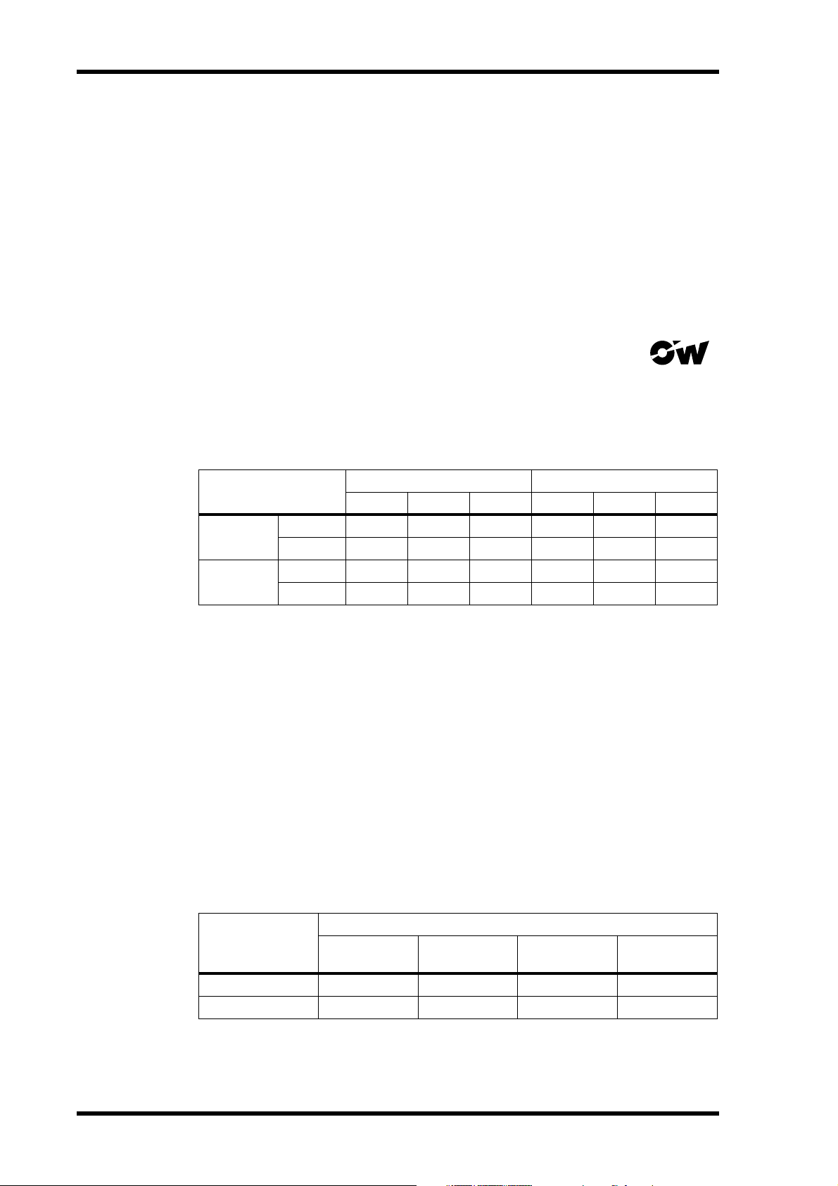
Overwrite-type disks feature the Overwrite logo shown here.
Tracks Available for Simultaneous Recording
The following table lists the number of tracks available for simultaneous recording with
a variety of normal and Overwrite-type MO disks at each recording resolution and
sampling rate.
Disk Type
16-bit 20-bit 24-bit 16-bit 20-bit 24-bit
640 MB
Overwrite
230 MB
640 MB
Normal
230 MB
44.1, 48 kHz 88.2, 96 kHz
888444
866433
866433
532211
For performance reasons, it’s recommended that you do not use 128 MB MO disks.
When tracks that have already been recorded are playing back, depending on the number and performance of those tracks (i.e., how heavily they’ve been edited), the number
of tracks available for simultaneous recording is reduced. Use the Optimize function to
arrange the recorded sound files for optimum performance. See “Recovering Disk
Space” on page 172 for more information.
Recording Time
The total recording time depends on the disk capacity, recording resolution, and sampling rate. A 640 MB Overwrite-type MO disk, for example, offers a total recording
time of 120 track minutes with a 16-bit recording resolution and 44.1 kHz sampling
rate.
The following table lists the approximate recording times offered by a variety of MO
disk capacities, with a 16-bit recording resolution and 44.1 kHz sampling rate.
Disk Capacity
640 MB
230 MB
D24—Owner’s Manual
Track minutes
Recording Time (16-bit, 44.1 kHz)
(mono)
120 min 60 min 30 min 15 min
43 min 21 min 10 min 5 min
2 tracks 4 tracks 8 tracks
Page 16

Choosing MO Disks
The following table lists the approximate recording times available using 640 MB MO
disks at a variety of recording resolutions and sampling rates.
16
20
24
Bit
Sampling
Rate
44.1 kHz
48 kHz
88.2 kHz
96 kHz
44.1 kHz
48 kHz
88.2 kHz
96 kHz
44.1 kHz
48 kHz
88.2 kHz
96 kHz
Track minutes
(mono)
120 min 60 min 30 min 15 min
111 min 55 min 27 min 13 min
60 min 30 min 15 min —
55 min 27 min 13 min —
96 min 48 min 24 min 12 min
88 min 44 min 22 min 11 min
48 min 24 min 12 min —
44 min 22 min 11 min —
80 min 40 min 20 min 10 min
74 min 37 min 18 min 9 min
40 min 20 min 10 min —
37 min 18 min 9 min —
2 tracks 4 tracks 8 tracks
7
Higher recording resolutions and sampling rates offer higher quality, but produce more
data, which reduces the total available recording time. Use the Remain function to
check the available recording time. See “Checking the Time Remaining” on page 38 for
more information.
The number of tracks available for simultaneous recording can be expanded using multiple D24s. See “Multiple D24s” on page 144 for more information.
The D24’s internal MO disk drive supports 230 MB, 540 MB, and 640 MB MO disks.
See the Yamaha Professional Audio Web site at the address below for up-to-date news
on MO disks.
<http://www.yamaha.co.jp/product/proaudio/homeenglish/>
Preformatted MO Disks
MO disks preformatted for use with PC or Macintosh computers can be used with the
D24, but require formatting before use. See “Formatting MO Disks” on page 26 for
more information.
Calculating the approximate Recording Time
You can calculate the approximate recording time for a given recording resolution,
sampling rate, and disk capacity as follows. First multiple the recording resolution by
the sampling rate to get the number of bits produced per second (e.g., 16
705,600 bits per second). Then divide that by eight to get the number of bytes per second (e.g., 705,600
of bytes required per minute (e.g., 88,200
÷
8 = 88,200 bytes per second). Multiply that by 60 to get the number
×
60 = 5,292,000 bytes per minute, or 5.292
MB/min). Now you know the number of megabytes required to store one minute of
audio data, simply divide the capacity of the disk by that number to get the approximate
number of track minutes (e.g., 640,000,000
÷ 5,292,000 = 120 minutes). Finally, divide
the number of track minutes by two, four, or eight to get the approximate recording
time available for several tracks (e.g., 120 ÷ 8 = 15 minutes for 8-track simultaneous
recording).
×
44100 =
D24—Owner’s Manual
Page 17

In this chapter...
Touring the D24 9
Touring the D24
2
Front Panel . . . . . . . . . . . . . . . . . . . . . . . . . . . . . . . . . . . . . . . . . . . . . . . . . . . . . . 10
Display . . . . . . . . . . . . . . . . . . . . . . . . . . . . . . . . . . . . . . . . . . . . . . . . . . . . . . . . . . 10
Transport Controls . . . . . . . . . . . . . . . . . . . . . . . . . . . . . . . . . . . . . . . . . . . . . . . . 12
Power Switch & Phones . . . . . . . . . . . . . . . . . . . . . . . . . . . . . . . . . . . . . . . . . . . . 14
Jog/Data & Shuttle/Cursor Controls . . . . . . . . . . . . . . . . . . . . . . . . . . . . . . . . . 15
Function Buttons . . . . . . . . . . . . . . . . . . . . . . . . . . . . . . . . . . . . . . . . . . . . . . . . . 16
Peak, Monitor, Format & Chase Buttons . . . . . . . . . . . . . . . . . . . . . . . . . . . . . . 17
Keypad . . . . . . . . . . . . . . . . . . . . . . . . . . . . . . . . . . . . . . . . . . . . . . . . . . . . . . . . . . 18
Track Buttons . . . . . . . . . . . . . . . . . . . . . . . . . . . . . . . . . . . . . . . . . . . . . . . . . . . . 19
Rear Panel . . . . . . . . . . . . . . . . . . . . . . . . . . . . . . . . . . . . . . . . . . . . . . . . . . . . . . . 20
D24—Owner’s Manual
Page 18
10 Chapter 2—Touring the D24
Front Panel
OVER
0
–dB
2
6
1012
1420
1830
20
42
2660
READY
RECORD
READY
SOLO/
SELECT
PEAK
HOLD
Display
TIME DISPLAY
AUTO
ALL
INPUT
INPUT
MONITOR SELECT
L
7654321
FORMAT CHASE
ABS H
OVER
0
–dB
00 00 00 00
2
6
12
20
30
42
LOCK
60
READY
R
8
0/-
MSF
YAMAHA D24
INT
WC
BITFSTC
7
4
1
48K
24
MASTER
8
9
5
6
2
3
LOCATEENTERCANCEL
PROJECT
SELECT
LOC MEM
RECALL
LOC MEM
STORE
CAPTURE ABS/REL
VARI
SPEED
V. TR ACK
SELECT
UTILITY
EDIT
JOG/DATA SHUTTLE/
REMAIN
SETUP
UNDO/
REDO
JOG ON
CURSOR
The D24 front panel is explained in the following sections.
1 2 3
PROJECT SEARCH
ROLL
RTN TO
BACK
ZERO
REW FF
DIGITAL MULTITRACK RECORDER
LAST REC
OUT
IN
A
B
STOP PLAY REC
SET
REPEAT
POWER
ON
OFF
AUTO
PUNCH
REHE
BA
010
PHONES
LEVEL
PHONES
R
OVER
0
–dB
2
6
12
20
30
42
60
READY
OVER
0
–dB
2
6
10 12
14 20
18 30
20
42
26 60
READY 12345678
L
ABS
REL
LOCK
CHASE
H
MSF
00 00 00 00
000000000000
000000000000
WC
BIT
INT EXT
16 20 24
44.1K48K96KVARI
FS
MASTER SLAVE
TC
4 9865 J7 K
A Level meters
These 16-segment track meters, with Peak Hold function, show playback and input signal levels from –60 dB to 0 dB. In Fine mode, they display levels from –26 dB to 0 dB.
The OVER indicator lights up when several consecutive audio samples exceed the digital saturation point. See “Metering” on page 39 for more information.
When the Shuttle, Nudge, Time Compression, or Pitch Change function is used, track
meters 7 and 8 function as stereo meters, and meters 1 through 6 are turned off.
B ABS/REL indicators
These indicators show whether the counter is displaying absolute (ABS) time or relative
(REL) time. See “Using Absolute & Relative Zero” on page 49 for more information.
D24—Owner’s Manual
Page 19

Display 11
C Counter
The main counter shows the current position in
hours, minutes, seconds, and frames,
(00:00:00.00), and can display the absolute
(ABS) time or relative (REL) time. See “Using
Absolute & Relative Zero” on page 49 for more
information.
The 2nd line of the message area displays time
information in hours, minutes, seconds, frames,
and sub-frames (00:00:00.00.0). Each sub-frame
is one tenth of a frame, making 10 sub-frames
per frame.
The 2nd line is also used to display the remaining recording time. See “Checking the
Time Remaining” on page 38 for more information.
Hour Min Sec fr
HMS F
00 00 00 00
STOP
000000000
Hour Min Sec fr sub-fr
D READY indicators
These indicators show which tracks are selected for recording. When a track is selected
for recording, the corresponding READY indicator flashes. During recording or
rehearsal, the corresponding indicator lights up continuously. See “Recording” on page
33 for more information.
E Message area
The message area consists of two lines that can each display up to 12 characters, which
typically show the status and operating mode of the D24, function and parameter
names and values, project titles and numbers, locate memory numbers, editing information, time values, and so on.
F LOCK indicator
This indicator shows whether or not the D24 is locked to the selected wordclock source.
See “Selecting a Wordclock Source” on page 124 for more information.
G CHASE indicator
This indicator shows whether or not the D24 is synchronized to the external timecode
source. It flashes when the D24 is chasing, and lights up continuously when it’s fully
synchronized. See “Chasing External Timecode” on page 138 for more information.
H WC window
This window shows the selected wordclock source: internal (INT) or external (EXT).
See “Selecting a Wordclock Source” on page 124 for more information.
I BIT window
This window shows the selected recording resolution: 16, 20, or 24. See “Setting the
Recording Resolution” on page 32 for more information.
J FS window
This window shows the selected sampling rate: 44.1 kHz, 48 kHz, 88.2 kHz, or 96 kHz.
When 88.2 kHz is selected, both the 44.1 kHz and 96 kHz indicators light up. See
“Selecting a Wordclock Source” on page 124 for more information.
The “VARI” indicator lights up when the Varispeed function is turned on. See “Using
Varispeed” on page 55 for more information.
K TC window
This window shows the selected timecode source: master or slave. When set to master,
the D24 uses internal timecode, and when set to slave, an external timecode source. See
“Selecting a Timecode Source” on page 135 for more information.
D24—Owner’s Manual
Page 20
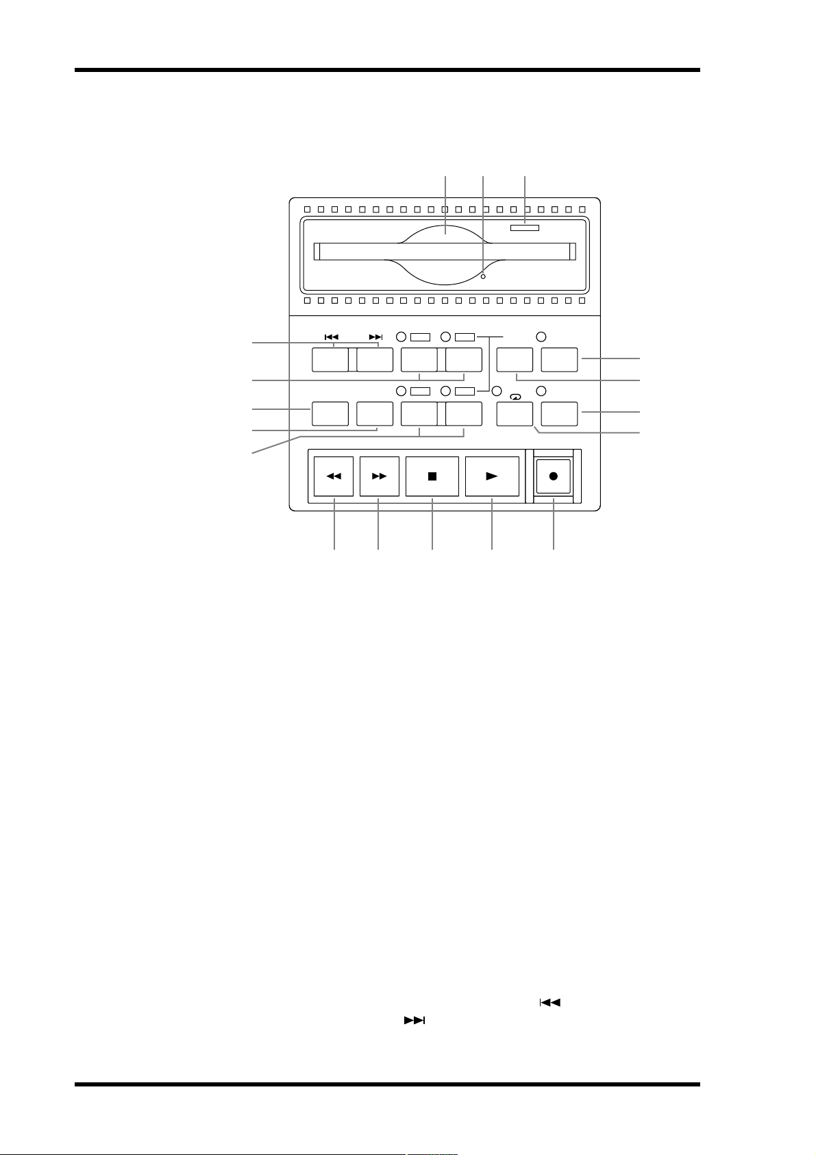
12 Chapter 2—Touring the D24
Transport Controls
5
4
3
2
1
PROJECT SEARCH
RTN TO
ZERO
ROLL
BACK
REW FF
6 7
LAST REC
OUT
IN
A
B
STOP PLAY REC
8
SET
REPEAT
BA
M N O P Q
AUTO
PUNCH
REHE
9
J
K
L
The “Transport Operation Table” on page 27 and the “Indicator Status Tables” on
page 28 list how the transport buttons and indicators function in each transport mode.
A A & B buttons & indicators
These buttons are used to set and locate the A and B points. The A and B indicators light
up when the respective A or B point is set. See “Using the A & B Points” on page 61 for
more information.
B ROLL BACK button
This button is used to roll back from the current position in steps of between 1 and 30
seconds, the default being 5 seconds. See “Using Roll-back” on page 50 for more information.
C RTN TO ZERO button
This button is used to locate the zero position. See “Returning to Zero” on page 60 for
more information.
D LAST REC IN & OUT buttons & indicators
These buttons are used to set and locate the LAST REC IN and LAST REC OUT points.
The IN and OUT indicators light up when the respective IN or OUT point is set. See
“Setting the LAST REC IN & OUT Points” on page 71 and “Locating the LAST REC IN
& OUT Points” on page 62 for more information.
E PROJECT SEARCH buttons
These buttons are used to search for projects. Pressing the [ ] button selects the top
of the current project. Pressing the [ ] button selects the top of the next project. See
“Searching for Projects” on page 58 for more information.
D24—Owner’s Manual
Page 21

Transport Controls 13
F MO disk drive slot
MO disks are loaded into the internal MO drive through this slot. See “Inserting &
Ejecting Disks” on page 25 for more information.
G Manual eject hole
This hole is used when disks cannot be ejected in the normal way. See “Ejecting Troublesome Disks (emergency use)” on page 174 for more information.
H Eject button & activity indicator
This button is used to eject MO disks, but also functions as a drive activity indicator,
lighting up when the disk drive is busy. See “Inserting & Ejecting Disks” on page 25 for
more information.
I AUTO PUNCH button & indicator
This button selects the Auto-Punch In/Out function. The AUTO PUNCH indicator
flashes when this function is on. See “Auto Punch In/Out Recording” on page 68 for
more information.
J SET button
This button is used in conjunction with the LAST REC [IN], LAST REC [OUT], [A],
and [B] buttons to set the LAST REC IN, LAST REC OUT, A, and B points, respectively.
See “Setting the LAST REC IN & OUT Points” on page 71 and “Setting the A & B
Points” on page 61 for more information. It’s also used in conjunction with the [RTN
TO ZERO] button to set the relative zero position. See “Using Absolute & Relative Zero”
on page 49 for more information.
The [SET] button is also used in conjunction with the [ENTER] button for the Auto
Memory Store function, and in conjunction with the [LOCATE] button to set the Keypad Timecode Input mode. See “Storing Locate Points Automatically” on page 65 and
“Locating Positions Directly” on page 63 respectively for more information.
K REHE button & indicator
This button is used to engage Rehearsal Standby mode and, when pressed together with
the [PLAY] button, punch in rehearsal. In Rehearsal mode, recording can be practiced,
with automatic playback and input monitor switching at the punch in and out points,
without actually recording anything to disk. The REHE button indicator flashes in
Rehearsal Standby mode, and lights up continuously during rehearsal. See “Rehearsing” on page 36, “Manual Punch In/Out Rehearsal” on page 69, and “Auto Punch
In/Out Rehearsal” on page 72 for more information.
L REPEAT button & indicator
This button selects the A–B Repeat playback function. The REPEAT indicator lights up
when this function is on. See “A–B Repeat Playback” on page 47 for more information.
M REW button
This button is used to start rewind. Press it once for rewind at 8x normal play speed, the
REW button indicator flashes. Press it again for rewind at 16x normal play speed, the
REW button indicator lights up continuously. Pressing and holding the REW button
during playback rewinds at 8x normal play speed.
N FF button
This button is used to start fast forward. Press it once for fast forward at 8x normal play
speed, the FF button indicator flashes. Press it again for fast forward at 16x normal play
speed, the FF button indicator lights up continuously. Pressing and holding the FF button during playback fast forwards at 8x normal play speed.
D24—Owner’s Manual
Page 22
14 Chapter 2—Touring the D24
O STOP button
This button is used to stop playback, recording, rehearsal, rewind, and fast forward, and
to cancel the Rehearse Standby mode. The STOP button indicator lights up when the
D24 is stopped.
P PLAY button
This button is used to start playback, punch out of recording or rehearsal, and in conjunction with the [REC] and [REHE] buttons, punch in for recording or rehearsal,
respectively. The PLAY button indicator lights up during playback, recording, and
rehearsal.
Q REC button
This button is used in conjunction with the [PLAY] button to start recording. The REC
button indicator lights up while recording. See “Recording” on page 29 for more information.
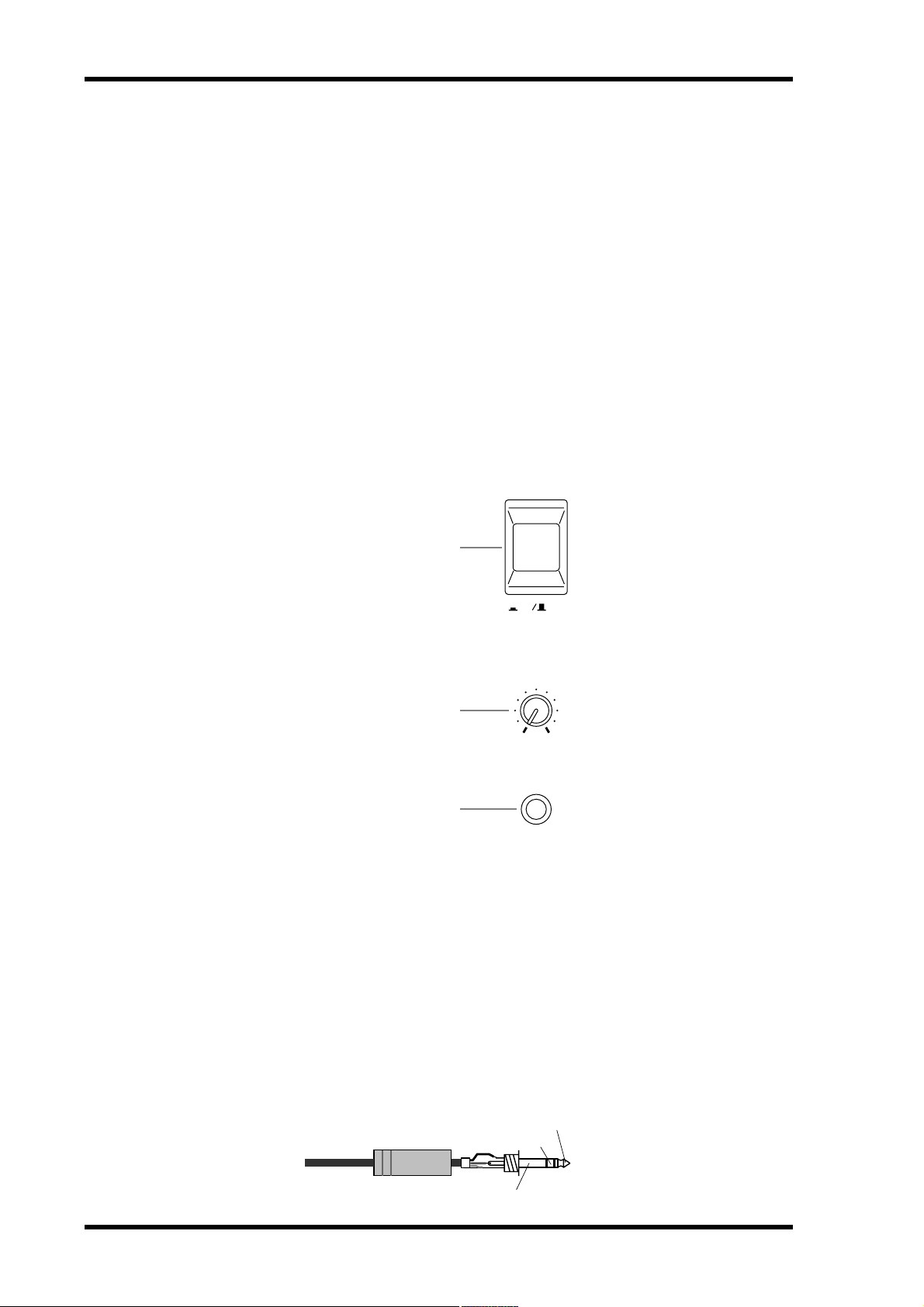
Power Switch & Phones
POWER
1
ON
OFF
2
010
PHONES
LEVEL
3
PHONES
A POWER switch
This switch is used to turn on and off the D24. It’s recessed to prevent accidental operation. See “Turning On & Off the D24” on page 24 for more information.
B PHONES LEVEL control
This control is used to adjust the volume level of the phones. See “Monitoring” on page
42 for more information.
C PHONES jack
A pair of stereo headphones can be connected to this stereo phone jack for monitoring.
See “Monitoring” on page 42 for more information.
The following illustration shows how the PHONES jack is wired.
1/4" TRS phone plug
D24—Owner’s Manual
Tip (left)
Ring (right)
Sleeve (ground)
Page 23

Jog/Data & Shuttle/Cursor Controls 15
Jog/Data & Shuttle/Cursor Controls
JOG ON
1
2
3
JOG/DATA SHUTTLE/
CURSOR
A JOG ON button & indicator
This button is used to turn on the Nudge and Shuttle functions. The JOG ON indicator
lights up when these functions are on. See “Nudging the Current Position” on page 53
and “Shuttling” on page 52 for more information.
B JOG/DATA dial
This is a dual-function control, the operation of which depends on the [JOG ON] button. When [JOG ON] is off, the JOG/DATA dial is typically used for time and data entry
and selecting parameters and functions on the display. Time values can be entered on
the 2nd line of the display using the keypad, and then adjusted up or down in sub-frame
steps using the JOG/DATA dial.
When [JOG ON] is on, the JOG/DATA dial is used to nudge the current position while
auditioning a small section of recorded material. See “Nudging the Current Position”
on page 53 for more information.
When the [VARI SPEED], [UTILITY], [SETUP], [V.TRACK SELECT], or [EDIT] button is pressed, the JOG/DATA dial is used to select functions and set parameter values.
C SHUTTLE/CURSOR ring
This is a dual-function control, the operation of which depends on the [JOG ON] button. When [JOG ON] is off, the SHUTTLE/CURSOR ring is used to move the cursor
on the display when selecting virtual tracks, titling projects, setting a timecode offset,
or setting the absolute start time for a new project.
When [JOG ON] is on, the SHUTTLE/CURSOR ring is used to shuttle forwards or
backwards at various speeds while auditioning the recorded material. See “Shuttling”
on page 52 for more information.
D24—Owner’s Manual
Page 24

16 Chapter 2—Touring the D24
Function Buttons
TIME DISPLAY
UTILITY
EDIT
REMAIN
SETUP
UNDO/
REDO
7
8
9
6
5
4
3
2
CAPTURE ABS/REL
VARI
SPEED
V . TRACK
SELECT
1
A EDIT button & indicator
This button is used to access the edit functions. The EDIT indicator lights up when this
button is pressed. The D24 must be stopped to use the edit functions. See “Editing
Projects” on page 77, “Editing Tracks” on page 85, and “Editing Parts” on page 95 for
more information.
B V. TRACK SELECT button & indicator
This button is used to access the Virtual Track function. The V. TRACK SELECT indicator lights up when the Virtual Track function is on. See “Using Virtual Tracks” on
page 51 for more information.
C UTILITY button & indicator
This button is used to access the utility functions. The UTILITY indicator lights up
when this button is pressed. The D24 must be stopped to use the utility functions.
D VARI SPEED button & indicator
This button is used to access the Varispeed function. The VARI SPEED indicator lights
up when the Varispeed function is on. The Varispeed function can be set while the D24
is stopped or during playback.See “Using Varispeed” on page 55 for more information.
E ABS/REL button
This button is used to set the counter mode to either Absolute (ABS), the default setting, or Relative (REL). See “Using Absolute & Relative Zero” on page 49 for more information.
F CAPTURE button
This button is used to capture time positions while the D24 is stopped or during
rewind, fast forward, playback, recording, or rehearsal. Captured values appear on the
2nd line of the display and can then be located or stored. See “Storing Locate Points” on
page 64 for more information.
G REMAIN button & indicator
This button turns on the Remain function, which shows how much recording time is
available. The REMAIN indicator lights up when the Remain function is on. See
“Checking the Time Remaining” on page 38 for more information.
H SETUP button & indicator
This button is used to access the setup functions. The SETUP indicator lights up when
this button is pressed. The D24 must be stopped to use the setup functions.
I UNDO/REDO button & indicator
This button is used to undo or redo the last recording or edit. See “Undoing a Recording
or Edit” on page 35.
D24—Owner’s Manual
Page 25

Peak, Monitor, Format & Chase Buttons 17
Peak, Monitor, Format & Chase Buttons
1 2 3 4 5
PEAK
HOLD
AUTO
INPUT
MONITOR SELECT
ALL
INPUT
FORMAT CHASE
A PEAK HOLD button & indicator
This button is used to turn the Peak Hold function on and off. The Peak Hold indicator
lights up when the Peak Hold function is on. See “Using Peak Hold” on page 41 for
more information.
B AUTO INPUT button & indicator
This button selects the Auto Input function. The Auto Input function works best with
punch in/out recording. The AUTO INPUT indicator lights up when the Auto Input
function is on.
Normally, when a track is selected for recording, its input signal is monitored during
recording. When the Auto Input function is on, however, track monitoring is automatically switches from playback to input signal at the punch-in point, and from input signal back to playback at the punch-out point. See “Monitoring” on page 42 for more
information.
C ALL INPUT button & indicator
This button selects the All Input function. When the All Input function is on, all track
inputs are monitored regardless of the transport mode, [RECORD READY] buttons.
The ALL INPUT indicator lights up when the All Input function is on. See “Monitoring” on page 42 for more information.
D FORMAT button & indicator
This button selects the Format function. The FORMAT indicator lights up when the
Format function is used. New MO disks and external disk drives must be formatted
before they can be used for recording with the D24. See “Formatting MO Disks” on
page 26 and “Formatting External Disk Drives” on page 158 for more information.
E CHASE button & indicator
This button selects Chase mode, in which the D24 synchronizes to an external timecode
source. The CHASE indicator lights up when the Chase function is on. See “Chasing
External Timecode” on page 138 for more information.
D24—Owner’s Manual
Page 26
18 Chapter 2—Touring the D24
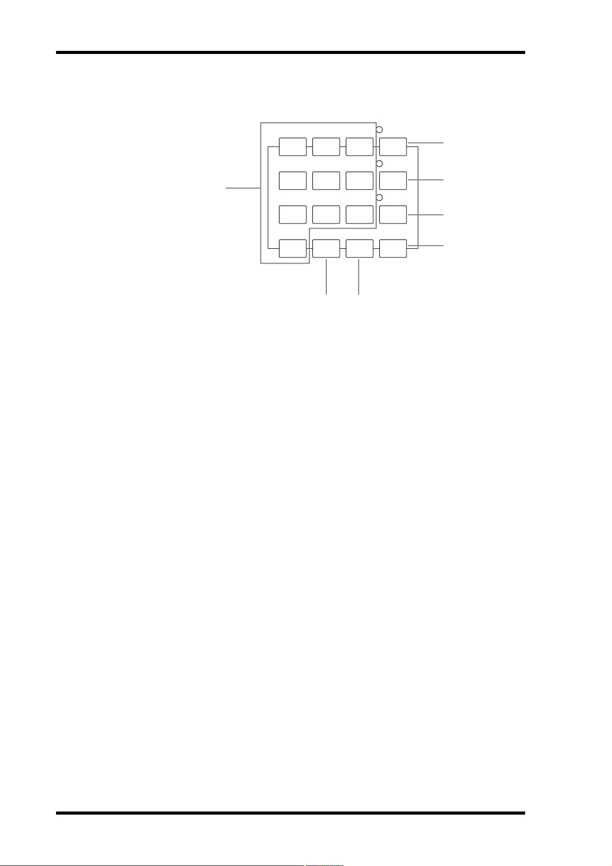
Keypad
1
PROJECT
7
8
9
SELECT
2
LOC MEM
4
5
6
RECALL
3
LOC MEM
1
2
3
STORE
4
LOCATEENTERCANCEL0/-
5
76
A Keypad buttons
The keypad is used with various functions to enter time values, parameter values,
project numbers, locate memory numbers, and so on.
The [0/-] is used to enter the number “0” and to make values plus or minus.
B PROJECT SELECT button & indicator
This button is used to select projects by number. The PROJECT SELECT indicator
lights up when the Project Select function is on. See “Selecting Projects Directly” on
page 59 for more information.
C LOC MEM RECALL button & indicator
This button is used to recall locate memories. The LOC MEM RECALL indicator lights
up when the Locate Memory Recall function is on. See “Recalling Locate Points” on
page 66 for more information.
D LOC MEM STORE button & indicator
This button is used to store locate memories. The LOC MEM STORE indicator lights
up when the Locate Memory Store function is on. See “Storing Locate Points” on page
64 for more information.
E LOCATE button
This button is used to locate the position specified on the 2nd line of the display. See
“Locating Positions Directly” on page 63 and “Recalling Locate Points” on page 66 for
more information.
F CANCEL button
This button is used to cancel functions and reset time values to zero on the 2nd line of
the display.
G ENTER button
This button is used to select, confirm, and execute functions.
D24—Owner’s Manual
Page 27

Track Buttons
1
RECORD
READY
Track Buttons 19
8
7654321
2
SOLO/
SELECT
A RECORD READY buttons 1–8
These buttons are used to select tracks for recording. When a track is selected for
recording, the corresponding READY indicator flashes. During recording or rehearsal,
the corresponding indicator lights up continuously. See “Recording” on page 33 for
more information.
B SOLO/SELECT buttons & indicators 1–8
These buttons are used to solo individual tracks. When a track is soloed, the corresponding SOLO/SELECT indicator lights up. See “Soloing Tracks” on page 48 for more
information.
D24—Owner’s Manual
Page 28
20 Chapter 2—Touring the D24
Rear Panel
3
VIDEO
OUTPUT
INPUT
75
75
ON OFF
TERM THRU
MODEL D24
DIGITAL MULTITRACK RECORDER
L M P Q RON
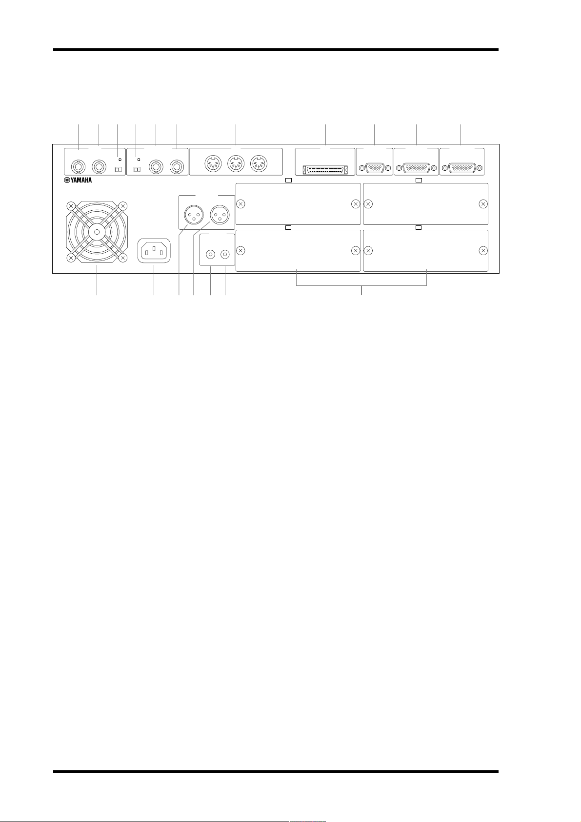
A VIDEO OUTPUT connector
B VIDEO INPUT connector
KJ9875 6421
WORD CLOCK
OUTPUT
AC IN
INPUT
OUTPUT INPUT
12
THRU OUT IN
TIME CODE
3
231
COAXIAL
OUTPUT INPUT
STEREO DIGITAL
MIDI
SERIAL I/OSCSI
SLOT 3 (ANALOG OUT)
SLOT 4 (ANALOG OUT)
SYNC OUT
SLOT 1 (ANALOG IN)
SLOT 2 (ANALOG IN)
This BNC connector transmits the video sync signal received at the VIDEO INPUT
when the VIDEO 75Ω ON/OFF switch is set to OFF. See “Using Video Sync” on page
149 for more information.
This BNC connector receives video sync signals (black burst or color bar). See “Using
Video Sync” on page 149 for more information.
REMOTE IN/
SYNC IN
C VIDEO 75Ω ON/OFF switch
This switch is used to terminate the video signal received at the VIDEO INPUT connector. When set to OFF, the video sync signal received at the VIDEO INPUT is transmitted
by the VIDEO OUTPUT connector. When set to ON, nothing is transmitted by the
VIDEO OUTPUT connector. See “Terminating BNC Video Sync Distribution” on page
150 for more information.
D WORD CLOCK 75Ω TERM/THRU switch
This switch is used to terminate the wordclock signal received at the WORD CLOCK
INPUT connector. See “Terminating BNC Wordclock Distribution” on page 131 for
more information.
E WORD CLOCK OUTPUT connector
This BNC connector transmits the wordclock signal received at the WORD CLOCK
INPUT when the WORD CLOCK 75Ω TERM/THRU switch is set to THRU, or the
internally generated wordclock signal when this switch is set to TERM. See “Wordclock
Connections” on page 123 for more information.
F WORD CLOCK INPUT connector
This BNC connector receives wordclock signals when the D24 is locked to an external
wordclock source. See “Wordclock Connections” on page 123 for more information.
G MIDI IN, OUT & THRU ports
These are standard MIDI IN, OUT, and THRU ports and are used to connect the D24
to other MIDI equipment for use with MTC (MIDI Timecode) and MMC (MIDI
Machine Control). See “MIDI Ports” on page 178 for more information.
D24—Owner’s Manual
Page 29

Rear Panel 21
H SCSI port
This 50-pin, half-pitch SCSI connector is used to connect external SCSI disk drives and
removable media drives for additional recording space. The SCSI interface supports
Narrow SCSI-2 (FAST-20). A personal computer equipped with SCSI can also be connected, which can then access files on the MO disk in the D24. See “SCSI & the D24”
on page 154 for more information.
I SERIAL I/O port
This 9-pin D-sub connector is used to connect the D24 to a video remote controller or
video editor for control using 9-pin protocols. See “Connecting a Video Editor” on page
151 for more information.
J SYNC OUT port
This 15-pin D-sub connector is used to connect multiple D24s in a synchronized system. In addition to various control signals, SYNC connections also carry wordclock
and timecode signals. See “Expanding the Number of Tracks” on page 145 for more
information.
K REMOTE IN/SYNC IN port
This 15-pin D-sub connector is used to connect multiple D24s in a synchronized system. It can also be used to connect an optional remote controller. In addition to various
control signals, SYNC connections also carry wordclock and timecode signals. See
“Expanding the Number of Tracks” on page 145 for more information.
L Cooling fan
The cooling fan keeps the internal components cool. See “Installing the D24” on page
3 for more information.
M AC IN connector
This connector is used to connect the D24 to an AC outlet, using the supplied power
cord. See “Connecting the Power Cord” on page 24 for more information.
N TIMECODE OUTPUT connector
This male XLR-3-32 connector (balanced) transmits internally generated SMPTE/EBU
timecode when the D24 is used as the timecode master, or the timecode received at
TIMECODE INPUT when the D24 is used as a timecode slave. See “Timecode Connections” on page 134 for more information.
O TIMECODE INPUT connector
This female XLR-3-31 connector (balanced) receives SMPTE/EBU timecode when the
D24 is used as a timecode slave. See “Timecode Connections” on page 134 for more
information.
P COAXIAL STEREO DIGITAL OUTPUT connector
This phono jack transmits S/PDIF format, 2-channel digital audio. See “Using the
Coaxial Digital Input & Output” on page 187 for more information.
Q COAXIAL STEREO DIGITAL INPUT connector
This phono jack receives S/PDIF format, 2-channel digital audio. See “Using the Coaxial Digital Input & Output” on page 187 for more information.
R SLOTs 1–4
These four slots are for use with optional mini YGDAI cards, which offer various analog
and digital I/O options. See “Digital Audio I/O” on page 181 for more information.
D24—Owner’s Manual
Page 30

In this chapter...
The Basics 23
The Basics
3
Connecting the Power Cord . . . . . . . . . . . . . . . . . . . . . . . . . . . . . . . . . . . . . . . . 24
Turning On & Off the D24 . . . . . . . . . . . . . . . . . . . . . . . . . . . . . . . . . . . . . . . . . 24
Write Protecting Disks . . . . . . . . . . . . . . . . . . . . . . . . . . . . . . . . . . . . . . . . . . . . . 24
Inserting & Ejecting Disks . . . . . . . . . . . . . . . . . . . . . . . . . . . . . . . . . . . . . . . . . . 25
Formatting MO Disks . . . . . . . . . . . . . . . . . . . . . . . . . . . . . . . . . . . . . . . . . . . . . 26
Transport Operation Table . . . . . . . . . . . . . . . . . . . . . . . . . . . . . . . . . . . . . . . . . 27
Indicator Status Tables . . . . . . . . . . . . . . . . . . . . . . . . . . . . . . . . . . . . . . . . . . . . . 28
D24—Owner’s Manual
Page 31

24 Chapter 3—The Basics
Connecting the Power Cord
Warning: Turn off all equipment before making any power connections.
Connect the socket-end of the supplied power cord to the AC IN
socket on the rear panel of the D24, and the plug-end to a suitable
AC wall outlet, one that conforms to the power supply requirements stated on the D24 rear panel.
Turning On & Off the D24
To prevent loud clicks and thumps in your loudspeakers, turn on your audio equipment in the following order (reverse this order when turning off your equipment)—sound sources, D24, mixing console, monitor amplifier.
Before turning on the D24, turn on any external disk drives connected to the D24’s SCSI port. Disk drives that are not turned on will
not be recognized by the D24. Drives that you do not intend to use
should be disconnected before turning on the D24. See “Using External Disk Drives” on page 154 for more information.
1 Press the [POWER] switch to turn on the D24.
After several seconds, “NO DISK” appears on the display and the D24
is ready for use.
AC IN
POWER
ON
OFF
2 Press the [POWER] switch again to turn off the D24.
Write Protecting Disks
MO disks feature write-protect tabs similar to those found on floppy disks, allowing
you to protect your recordings against accidental overwriting.
When the write-protect tab window is open, the disk is write protected and cannot be
used for recording or editing. When the write-protect tab window is closed, the disk is
unprotected and both recording and editing are possible.
Individual projects can be protected using the Project Edit Protect function. See “Protecting Projects” on page 82 for more information.
D24—Owner’s Manual
Page 32

Inserting & Ejecting Disks 25
Inserting & Ejecting Disks
This section explains how to insert and eject MO disks.
1 Insert the MO disk into the disk drive with the shutter facing forward and the
labeled side facing up, as shown below. Push it in until it clicks into place.
O
UT
A
H
C
N
U
P
T
E
S
C
E
T R
S
T
LA
U
O
H
IN
RC
A
E
T S
C
E
J
O
R
P
LL
O
R
K
AC
B
O
T
RTN
RO
ZE
FF
W
E
R
B
A
L
P
P
O
T
S
E
H
E
R
T
A
E
P
E
R
BA
C
E
R
Y
A
The disk should slide easily into the disk drive. If it doesn’t, make sure that you’ve
inserted it the right way around.
When a disk is inserted, “DISK LOADED” appears on the display.
If the disk has already been used for recording in the D24, the number and title of the
first project appear on the display. If the disk has been formatted for use with the D24
but not yet used for recording, “01 NO TITLE” is displayed.
2 To eject a disk, press the eject button, as shown below.
O
UT
A
CH
N
U
P
T
E
S
C
E
R
T
T
AS
L
U
CH
R
A
E
S
T
C
E
J
O
R
P
L
O
R
C
A
B
O
T
N
RT
O
R
E
Z
FF
W
E
R
O
IN
B
A
L
K
P
P
O
T
S
HE
E
R
AT
E
P
E
R
BA
C
RE
AY
L
The eject button also functions as a drive activity indicator, lighting up when the disk
drive is busy.
The eject button does not operate during recording and should not be pressed simultaneously with another button, as this may cause a malfunction.
D24—Owner’s Manual
Page 33

26 Chapter 3—The Basics
Formatting MO Disks
New MO disks and MO disks that have been used to store other kinds of data must be
formatted before they can be used in the D24. The formatting process prepares a disk
for storing D24 data. Formatting erases all previously stored data, so if you’re reusing a
disk, make sure that it contains no important data before formatting.
Before formatting a disk, set the sampling rate as required. If the sampling rate is
changed after formatting, project start times other than 00:00:00.00 may change. If the
start time does change, use the TC Modify function to correct it. See “Modifying a
Project’s Start Time” on page 83 for more information.
1 Insert the disk into the D24 disk drive.
If the disk is new or has been formatted for use in a device other than the D24, the message “UNFORMATTED” appears on the display.
2 Press the [FORMAT] button.
The FORMAT indicator flashes and “FORMAT DISK—ARE YOU SURE” flashes on
the display.
3 Press the [ENTER] button.
“PRESS—REC + PLAY” appears on the display.
4 Press the [REC] and [PLAY] buttons simultaneously to format the disk, or the
[CANCEL] button to cancel the Format function.
While the disk is being formatted, “FORMATTING” appears on the display.
When formatting is complete, “FINISHED” appears on the display, the FORMAT indicator goes out, and “01 NEW PROJ” appears on the display.
5 If you want to set the absolute start time of project 01 to a time other than
“00:00:00.00,” set it now. See “Recording” on page 33 for more information.
Otherwise, press the [ENTER] button.
The absolute start time for subsequent projects can be specified as and when they are
recorded.
The MO disk is now ready for use.
D24—Owner’s Manual
Page 34

Button
Transport Operation Table
The following table shows the function of each control in each transport mode.
X = no change or invalid
Transport Mode
Stop Play Rew FF Record
Transport Operation Table 27
Rehearse
Standby
Rehearse
Nudge/
Shuttle
A–B
Repeat
Rew (8x)
[REW]
[FF]
[STOP]
[PLAY]
[REC]
[REHE]
Eject
1. Release button for normal playback.
Rew (8x)
FF (8x)
X Stop play Stop rew Stop FF
Play X
X
Rehearse
standby
Eject X X X X
while
pressing
FF (8x)
while
pressing
REC+PLAY
to start
recording
Rehearsal
punch in
Rew
(16x)
Stop rew
& FF
Stop rew
& play
XXXXXXX
X X X Cancel X X
Stop FF
& rew
FF
(16x)
Stop FF
& play
Stop rec &
rew
Stop rec &
FF
Punch out
& stop
Punch out
& play
Rew
FF
Cancel &
stop
Rehearsal
punch in
Cancel &
eject
Stop
rehearsal &
rew
Stop
rehearsal &
FF
Punch out &
stop
Punch out &
play
XXX
Cancel &
rew
Cancel &
Cancel &
stop
Cancel &
play
FF
Cancel &
1
rew
Cancel &
1
FF
Stop play
X
Cancel &
rehearsal
punch in
D24—Owner’s Manual
Page 35

28 Chapter 3—The Basics
Indicator Status Tables
The following tables show the status and meaning of the front-panel indicators.
Transport Indicators
● On z Flashing - Off
Indicator
REW 8x
REW 16x
FF 8x
FF 16x
STOP
PLAY
REC
REHE
READY
(REC READY=OFF)
READY
(REC READY=ON)
1
Eject
Stop Play Rew/FF Record
--
--
--
--
●
-
---
----
--------
zzz
-
Transport Mode
Rehearse
Standby
z
●
z
●
-------
●
-
-----
-----
-----
-----
●
●
z
z
●
-
z
z
Rehearse
-
----
●●●
●
●
-
zzz
Nudge/
Shuttle
--
A–B
Repeat
zz
1. Indicates drive activity. Lights up continuously when a disk is being loaded or ejected.
Other Indicators
● On - Off
Indicator Status Condition
LAST REC IN
LAST REC OUT
A
B
UNDO/REDO
SOLO/SELECT
Other front-panel indicators typically indicate whether a function is on or off.
- LAST REC IN point has not been set
LAST REC IN point has been set
●
- LAST REC OUT point has not been set
LAST REC OUT point has been set
●
- A point has not been set
A point has been set
●
- B point has not been set
B point has been set
●
- Last record or edit operation has not been undone
Last record or edit operation has been undone
●
- Track not soloed
Track soloed
●
D24—Owner’s Manual
Page 36

In this chapter...
Recording 29
Recording
4
About Projects . . . . . . . . . . . . . . . . . . . . . . . . . . . . . . . . . . . . . . . . . . . . . . . . . . . . 30
Preparing to Record . . . . . . . . . . . . . . . . . . . . . . . . . . . . . . . . . . . . . . . . . . . . . . . 31
Setting the Recording Resolution . . . . . . . . . . . . . . . . . . . . . . . . . . . . . . . . . . . . 32
Recording . . . . . . . . . . . . . . . . . . . . . . . . . . . . . . . . . . . . . . . . . . . . . . . . . . . . . . . . 33
Conserving Disk Space . . . . . . . . . . . . . . . . . . . . . . . . . . . . . . . . . . . . . . . . . . . . . 35
Undoing a Recording or Edit . . . . . . . . . . . . . . . . . . . . . . . . . . . . . . . . . . . . . . . . 35
Rehearsing . . . . . . . . . . . . . . . . . . . . . . . . . . . . . . . . . . . . . . . . . . . . . . . . . . . . . . . 36
Extending the Top of a Project . . . . . . . . . . . . . . . . . . . . . . . . . . . . . . . . . . . . . . 37
Checking the Time Remaining . . . . . . . . . . . . . . . . . . . . . . . . . . . . . . . . . . . . . . 38
Metering . . . . . . . . . . . . . . . . . . . . . . . . . . . . . . . . . . . . . . . . . . . . . . . . . . . . . . . . . 39
Using Normal & Fine Metering . . . . . . . . . . . . . . . . . . . . . . . . . . . . . . . . . . . . . 40
Using Peak Hold . . . . . . . . . . . . . . . . . . . . . . . . . . . . . . . . . . . . . . . . . . . . . . . . . . 41
Monitoring . . . . . . . . . . . . . . . . . . . . . . . . . . . . . . . . . . . . . . . . . . . . . . . . . . . . . . 42
D24—Owner’s Manual
Page 37

30 Chapter 4—Recording
About Projects
D24 recordings are organized as projects, with a typical project consisting of many
sound files and a settings file. Up to 99 projects can be recorded on a single MO or external disk drive. The following settings are stored with each project: recording resolution
(BIT), sampling rate (FS), timecode frame rate, absolute start time, project title, virtual
track assignments, relative zero position, up to 99 locate points, and the LAST REC IN,
OUT, A, and B locate points, as shown in the following illustration. The wordclock
source (WC) and timecode source (TC) settings are not stored with each project.
WC: INT
TC: MASTER
BIT: 16
FS: 44.1 kHz
Frame rate: 30
Start: 00:00:00.00
Title: POP SONG
Virtual track assignments
Rel: 00:00:00.00
LOC MEM
LAST REC IN, OUT, A, B
Internal or external wordclock source (INT, EXT)
Timecode master or slave (MASTER, SLAVE)
Recording resolution (16, 20, 24)
Sampling rate (44.1 kHz, 48 kHz, 88.2 kHz, 96 kHz)
Timecode frame rate (24, 25, 30D, 30)
Absolute start time of project
Project title
1-1, 2-3, 3-4, 4-4, etc
Relative zero position
Locate points 1–99
IN, OUT, A, & B points
Highlighted settings are stored with each project
The following illustration shows four example projects and their associated settings.
00:00:00.00
01 PROJECT 02 PROJECT 03 PROJECT 04 PROJECT
WC: INT
TC: MASTER
BIT: 16
FS: 44.1 kHz
Frame rate: 30
Start: 00:00:00.00
Title: POP SONG
V.TRK assign: 1-1...
Rel: 00:00:00.00
LOC MEM: 1–99
IN: 00:01:05.12
OUT: 00:01:30.29
A: 00:00:20.00
B: 00:00:45.00
00:10:00.00
WC: INT
TC: MASTER
BIT: 24
FS: 96 kHz
Frame rate: 24
Start: 00:10:00.00
Title: DVD X
V.TRK assign: 1-1...
Rel: 00:00:00.00
LOC MEM: 1–99
IN: 00:11:05.12
OUT: 00:11:30.23
A: 00:10:20.00
B: 00:10:45.00
01:00:00.00
WC: EXT
TC: SLAVE
BIT: 16
FS: 44.1 kHz
Frame rate: 30D
Start: 01:00:00.00
Title: TVCM
V.TRK assign: 1-1...
Rel: 00:00:00.00
LOC MEM: 1–99
IN: 01:01:05.12
OUT: 01:01:30.29
A: 01:00:20.00
B: 01:00:45.00
23:30:00.00
WC: EXT
TC: SLAVE
BIT: 20
FS: 48 kHz
Frame rate: 30D
Start: 23:30:00.00
Title: NEWS
V.TRK assign: 1-1...
Rel: 00:00:00.00
LOC MEM: 1–99
IN: 23:31:05.12
OUT: 23:13:30.29
A: 23:31:20.00
B: 23:31:45.00
The recording resolution and sampling rate are set when a new project is created, and
once something has been recorded in a project, cannot be changed. Although a project
can be played with a timecode frame rate different to that used when it was originally
recorded, stored locate memories will be out of sync with the recorded material, so in
addition to the recording resolution and sampling rate, it’s best to set the timecode
frame rate as required before recording each new project.
When an already recorded project is selected, the D24 automatically sets the recording
resolution and timecode frame rate, using the settings stored with that particular
project. If the project’s sampling rate is different to the current setting, the project’s
sampling rate flashes in the FS window and you must use the Wordclock function
(“Selecting a Wordclock Source” on page 124) to set the sampling rate of the D24 to
match that of the project, otherwise, playback will be distorted.
D24—Owner’s Manual
Page 38

Preparing to Record 31
Projects recorded using an external wordclock source can also be played, edited, or
recorded using an internal wordclock source, and vice versa. A project originally
recorded with an external wordclock source running at 44.1 kHz, for example, can also
be used with an internal wordclock of 44.1 kHz.
Projects recorded using an external timecode source can be played, edited, or recorded
using an internal timecode source even at a different frame rate, and vice versa. A
project originally recorded with an external timecode source running at 30 fps, for
example, can also be used with an internal timecode source of 25 fps.
When recording a new project, the counter initially displays 00:00:00.00. If this value is
not changed, it’s used as the absolute start time for the new project. You can, however,
specify a different start time.
New projects are numbered using the next available project number. If the highest
numbered project on disk is 06, for example, the next new project will be 07. Projects
can be titled for easy identification. See “Titling Projects” on page 81 for more information.
D24 disks contain sound files and project settings files.
Sound files
Project settings files
Preparing to Record
This section explains how to prepare for recording.
1 Select a wordclock source.
See “Selecting a Wordclock Source” on page 124 for more information. Although the
wordclock source can be changed after recording, the sampling rate cannot be changed
once something is recorded in a project.
2 If you’re using a brand-new disk, format it.
See “Formatting MO Disks” on page 26 or “Formatting External Disk Drives” on
page 158 for more information.
3 Select a timecode source.
See “Selecting a Timecode Source” on page 135 for more information. The timecode
source can be changed after recording.
4 Set the timecode frame rate.
See “Setting the Timecode Frame Rate” on page 136 for more information.
5 Set the recording resolution.
See “Setting the Recording Resolution” on page 32 for more information. The recording
resolution cannot be changed once something is recorded in a project.
6 Proceed to “Recording” on page 33.
D24—Owner’s Manual
Page 39

32 Chapter 4—Recording
Setting the Recording Resolution
The recording resolution can be set to one of three bit rates: 16, 20, or 24. Once something has been recorded in a project, the recording resolution cannot be changed, so it’s
important that you set the correct resolution when creating a new project.
1 Press the [SETUP] button.
The SETUP indicator lights up.
2 Use the JOG/DATA dial to select “REC BIT,” and then press the [ENTER] button.
The currently selected recording resolution appears on the display.
3 Use the JOG/DATA dial to select a recording resolution.
The recording resolution can be set to 16, 20, or 24. The default setting is 24.
4 Press the [ENTER] button to activate your selection, or the [CANCEL] button
to cancel the Rec Bit function.
The selected resolution appears in the BIT window on the display, as
shown here.
5 Press the [SETUP] button again to leave setup.
The SETUP indicator goes out.
The following table lists the theoretical dynamic range available with each resolution.
BIT
BIT
BIT
16
20
24
Recording Resolution Theoretical Dynamic Range
16
20
24
96 dB
120 dB
144 dB
Higher recording resolutions offer improved sonic performance by increasing the
dynamic range, but require more disk space. A 640 MB Overwrite-type MO disk, for
example, can store approximately 120 track minutes of 16-bit, 44.1 kHz digital audio,
compared with 80 track minutes of 24-bit, 44.1 kHz digital audio.
The recording resolution you choose will ultimately depend on your application and
recording system. There’s no point selecting a 20- or 24-bit recording resolution on the
D24 if your digital mixing console’s A/D converters are only 16-bit. If you intend to
deliver your project to a third party, another studio, for example, consult them and
agree on a recording resolution before you start recording on the D24.
In general, 16-bit is the standard for music CDs and MiniDiscs, while 20- and 24-bit are
used for professional recording and mastering applications, although you don’t have to
select the same resolution as that of the final distribution media. In fact, recording, mixing, and mastering at a higher resolution will most likely yield a better result. In a 16-bit
system, for example, it’s necessary to keep recording levels high to make best use of the
96 dB dynamic range and maximize signal-to-noise performance, which restricts headroom and constrains level setting. In a 24-bit system, levels can be set lower due to the
larger 144 dB dynamic range, providing additional headroom, while maintaining signal-to-noise performance.
Low-resolution digital audio signals can easily be transferred to higher-resolution systems, however, the reverse is not true. A 20-bit digital signal recorded on a 16-bit
recorder without digital dither will be truncated, resulting in distortion. See “Digital
I/O & Wordlength” on page 189 for more information.
D24—Owner’s Manual
Page 40

Recording 33
Recording
Before recording a new project, you must first set the wordclock source, timecode
source, timecode frame rate, and recording resolution. See “Preparing to Record” on
page 31 for more information.
The following illustration shows the procedure for recording.
READY 2
1-1
2-1
3-1
4-1
5-1
6-1
7-1
8-1
1
2
3
4
5
6
7
8
RECORD
READY
LAST REC IN
point
2
REC
LAST REC OUT
point
Record
STOPPLAY
1 Press the [ ] PROJECT SEARCH button repeatedly until “nn NEW PROJ”
appears on the display (“nn” being the number of the new project). If the
disk has just been formatted, this will already be displayed, so you can ignore
this step.
The 2nd line of the display shows “00:00:00.00,” which is the absolute start time for the
new project.
2 If you want to change the absolute start time, use the keypad or JOG/DATA
dial to enter a time.
Use the SHUTTLE/CURSOR ring to move the cursor. Press the [CANCEL] button to
return to the previous value.
3 Press the [ENTER] button.
The absolute start time appears on the main counter.
4 Use the [RECORD READY] buttons to select tracks for recording.
The corresponding READY indicators flash.
5 Set the recording levels in conjunction with the D24 track meters.
See “Metering” on page 39 for more information. Recording levels are typically set
using the group, or bus output faders on the mixing console.
6 Select a monitoring mode.
See “Monitoring” on page 42 for more information.
7 Press the [REC] and [PLAY] buttons simultaneously to start recording.
Recording starts, “nn RECORDING” appears on the display (“nn” being the project
number), and the REC and PLAY button indicators and READY indicators light up
continuously. The LAST REC IN point is set automatically and its indicator lights up.
D24—Owner’s Manual
Page 41

34 Chapter 4—Recording
If the [PLAY] button is pressed while recording, the D24 punches out of recording and
continues with normal playback, in which case the REC button indicator goes out, the
READY indicators flash, and the LAST REC OUT point is set.
8 Press the [STOP] button to stop recording.
The REC and PLAY button indicators go out and the READY indicators flash. The
LAST REC OUT point is set automatically and its indicator lights up.
To audition what you’ve just recorded, press the LAST REC [IN] button to locate the
point at which recording started, and then press the [PLAY] button to start playback.
Recording can be undone using the Undo Function. See “Undoing a Recording or Edit”
on page 35 for more information.
Projects can be titled using the Project Edit Title function. See “Titling Projects” on page
81 for more information. When an untitled project is selected, “NO TITLE” appears on
the display.
D24—Owner’s Manual
Page 42

Conserving Disk Space 35
Conserving Disk Space
Like all digital audio recorders, the D24 uses up disk space regardless of what’s being
recorded, so recorded silence uses as much disk space as recorded music. A two minute
section of continuous music, for example, will use the same amount of disk space as a
two minute section of silence. Obviously, it’s wasteful to leave the D24 recording silence
longer than necessary.
Disk space can be conserved by recording only when there’s something that actually
needs recording. When recording material with long silent sections, for example, you
could save disk space by punching out of recording during those sections.
The disk space occupied by the recorded silences can be retrieved for additional recording by first deleting the silent sections, using the Part Erase function, see “Erasing Parts”
on page 104, and then optimizing the disk, using the Optimize function, which deletes
unused sound files from disk, thereby freeing up space for additional recording, see
“Recovering Disk Space” on page 172.
Undoing a Recording or Edit
The Undo function can be used to undo the last recording or edit. After recording or
performing an edit, the UNDO/REDO indicator lights up, indicating that the Undo
function can be used.
1 Press the [UNDO/REDO] button.
The last recording or edit is undone and the UNDO/REDO indicator goes out. When
the last recording is undone, the previous recording (i.e., the recording that was overwritten), if any, is restored.
2 Press the [UNDO/REDO] button again to redo the last recording or edit.
The UNDO/REDO indicator lights up.
As well as undoing unneeded recordings or edits, the Undo function provides a convenient way to compare the previous and last recording, or edit.
D24—Owner’s Manual
Page 43

36 Chapter 4—Recording
Rehearsing
In Rehearsal mode, recording can be practiced, with automatic playback and input
monitor switching at the punch in and out points, without actually recording anything
to disk.
The following illustration shows the procedure for rehearsal.
LAST REC OUT
point
STOPPLAY
READY 2
1-1
2-1
3-1
4-1
5-1
6-1
7-1
8-1
RECORD
READY
LAST REC IN
point
1
2
3
4
5
6
7
8
Rehearse
2
REHE
Rehearse Standby
1 Set wordclock source, timecode source, timecode frame rate, and recording
resolution. See “Preparing to Record” on page 31 for more information.
2 Use the [RECORD READY] buttons to select tracks for recording.
The corresponding READY indicators flash.
3 Set the recording levels in conjunction with the D24 track meters.
See “Metering” on page 39 for more information. Recording levels are typically set
using the group, or bus output faders on the mixing console.
4 Select a monitoring mode.
See “Monitoring” on page 42 for more information.
5 Press the [REHE] button.
The REHE button indicator flashes, indicating Rehearse Standby mode.
To cancel Rehearse Standby mode, press the [STOP] button.
6 Press the [PLAY] button to start rehearsal.
Rehearsal starts and the PLAY button indicator and READY indicators light up continuously. The LAST REC IN point is set automatically and its indicator lights up.
Rehearsal can also be started by pressing the [PLAY] and [REHE] buttons simultaneously.
If the [PLAY] button is pressed during rehearsal, the D24 punches out of rehearsal, continues with normal playback, and sets the LAST REC OUT point.
7 Press the [STOP] button to stop rehearsal.
The REHE and PLAY button indicators go out and the READY indicators flash. The
LAST REC OUT point is set automatically and its indicator lights up.
D24—Owner’s Manual
Page 44

Extending the Top of a Project 37
Extending the Top of a Project
Since it’s not possible to record before the absolute 00:00:00.00 position of a recorded
project, if you need to record something new at the top of a project, for example, you
need to extend the intro of a song, you must use the Track Slip function to slip forward
the tracks already recorded, and then record the new material. See “Slipping Tracks” on
page 93 for more information.
In the following example, a project’s absolute start time is 00:00:00.00. Using the Track
Slip function, the four recorded tracks are slipped forward eight seconds, so that new
material can be recorded at the top of the project.
00:00:00.00
1
2
3
4
1
2
3
4
Tracks moved
forward 8 seconds
00:00:08.00
Before track slip
After track slip
D24—Owner’s Manual
Page 45

38 Chapter 4—Recording
Checking the Time Remaining
The Remain function displays how much time is available for additional recording.
1 Press the [REMAIN] button.
The amount of time left for additional recording is displayed on the 2nd line of the display, as shown below.
The Remain function displays the recording time available relative to the number of
tracks selected for recording. For example, you can check the simultaneous recording
time available for four tracks by pressing four [RECORD READY] buttons, and then
pressing the [REMAIN] button. In the following example, tracks 1 through 4 are
selected for recording and the Remain function displays the recording time available for
four tracks.
HMS F
00 00 00 00
R- 006040000
HMS F
00 00 00 00
R- 001510000
READY 1 2 3 4 5 6 7 8
When tracks, or parts are erased or deleted, although they can no longer be accessed,
the actual audio data remains on disk as unused sound files, taking up disk space, and
reducing the time available for additional recording. After repeated recording and editing, there may be a lot of unused sound files on the disk. To delete these unused sound
files and recover the disk space for further recording or editing, use the Optimize function. See “Recovering Disk Space” on page 172 for more information.
D24—Owner’s Manual
Page 46

Metering 39
Metering
Playback and input signal levels are displayed on the eight 16-segment track meters,
with Peak Hold, and Normal and Fine metering modes.
The 0 dB indicators light up when audio samples reach the maximum digital level. The
OVER indicators light up when several consecutive samples exceed the digital saturation point. When setting recording levels, it’s okay for signals to light the 0 dB indicator.
If the OVER indicator lights up, however, you should back off the input level, as shown
below.
Okay Back off recording level
R
OVER
0
–dB
2
6
12
20
30
42
60
READY
OVER
–dB
READY
0
2
6
12
20
30
42
60
L
When the Shuttle, Nudge, Time Compression, or Pitch Change function is used, track
meters 7 and 8 function as stereo meters, and meters 1 through 6 are turned off.
D24—Owner’s Manual
Page 47

40 Chapter 4—Recording
Using Normal & Fine Metering
Track meters function in one of two modes: Normal or Fine. In Normal mode, the
meter range is from –60 dB to 0 dB. In Fine mode, it’s from –26 dB to 0 dB.
Normal
Fine
OVER
–dB
READY
OVER
–dB
FINE
10 12
14 20
18 30
20
26 60
READY
OVER
R
R
0
–dB
2
6
12
20
30
42
60
READY
OVER
0
–dB
FINE
2
6
12 10
20 14
30 18
20
42
60 26
READY
0
2
6
12
20
30
42
60
L
0
2
6
42
L
Fine mode is useful for accurate level setting when recording reference tones at –10,
–14, –18, or –20 dB, but can also be used for precise metering with normal recording.
The normal and fine meter modes are set using the Level Meter function.
1 Press the [UTILITY] button.
The UTILITY indicator lights up.
2 Use the JOG/DATA dial to select “LEVEL METER,” and then press the [ENTER]
button.
The currently selected meter mode appears on the display.
3 Use the JOG/DATA dial to select either “NORMAL” or “FINE.”
4 Press the [ENTER] button to activate your selection, or the [CANCEL] button
to cancel the Level Meter function.
5 Press the [UTILITY] button again to leave utility.
The UTILITY indicator goes out.
D24—Owner’s Manual
Page 48

Using Peak Hold 41
Using Peak Hold
By keeping the highest lit segment of each meter illuminated, the Peak Hold function
provides a convenient way to check for signal peaks.
Peak Hold can be set so that the highest lit segment of each meter remains lit for 800 ms
(MOMENTARY) or continuosuly (PERMANENT). See “Setting the Peak Hold Mode”
on page 170 for more information.
1 Press the [PEAK HOLD] button to turn on the Peak Hold function.
The PEAK HOLD indicator lights up.
2 Press the [PEAK HOLD] button again to turn off the Peak Hold function.
The PEAK HOLD indicator goes out.
To reset the Peak Hold function, turn it off and then on again.
Peak Hold: Off
Peak Hold: On
OVER
–dB
READY
OVER
–dB
READY
0
2
6
12
20
30
42
60
Peak levels
0
2
6
12
20
30
42
60
OVER
0
–dB
2
6
12
20
30
42
60
READY
L
L
R
R
OVER
0
–dB
2
6
12
20
30
42
60
READY
D24—Owner’s Manual
Page 49

42 Chapter 4—Recording
Monitoring
In a typical D24 multitrack recording system, monitoring is performed at the mixing
console via the tape returns, which are connected to the D24’s track outputs via mini
YGDAI cards (“About mini YGDAI Cards” on page 182). The signal source for each
track output, either playback or input signal, depends on that track’s [RECORD
READY] button setting, the transport mode (e.g., stop, playback, or record), and the
[AUTO INPUT] and [ALL INPUT] MONITOR SELECT buttons, as shown in the following illustrations.
The disk and plug symbols used in the following illustrations are explained below.
AUTO
INPUT
MONITOR SELECT
ALL
INPUT
Track output source:
Input signalPlayback
In the following illustration, the [AUTO INPUT] and [ALL INPUT] buttons are both
turned off. Tracks not selected for recording don’t output anything during stop, fast forward, or rewind, but output playback signals during playback, recording, or rehearsal.
Tracks selected for recording output the track input signal regardless of the transport
mode.
LAST REC OUT
point
PlaybackStop/FF/Rew
READY 1
READY 1
Playback
LAST REC IN
point
Recording/
Rehearsal
In the following illustration, the [AUTO INPUT] button is turned on, the default setting. Tracks not selected for recording function as before. Tracks selected for recording,
however, output playback signals during playback, but switch to track input signals
during recording or rehearsal. This setting is convenient for punch in/out recording.
AUTO
INPUT
MONITOR SELECT
D24—Owner’s Manual
ALL
INPUT
READY 1
READY 1
Playback
LAST REC IN
point
Recording/
Rehearsal
LAST REC OUT
point
PlaybackStop/FF/Rew
Page 50

Monitoring 43
In the following illustration, the [ALL INPUT] button, which has priority over all other
settings, is turned on and the track outputs output the track input signals regardless of
the transport mode and [RECORD READY] button. All Input is useful when you want
to monitor track inputs regardless of any other settings.
AUTO
INPUT
MONITOR SELECT
ALL
INPUT
READY 1
READY 1
LAST REC IN
point
PlaybackStop/FF/Rew
Recording/
Rehearsal
LAST REC OUT
point
Playback
D24—Owner’s Manual
Page 51

In this chapter...
General Operation 45
General Operation
5
Using Playback . . . . . . . . . . . . . . . . . . . . . . . . . . . . . . . . . . . . . . . . . . . . . . . . . . . 46
Using Fast Forward & Rewind . . . . . . . . . . . . . . . . . . . . . . . . . . . . . . . . . . . . . . 46
A–B Repeat Playback . . . . . . . . . . . . . . . . . . . . . . . . . . . . . . . . . . . . . . . . . . . . . . 47
Soloing Tracks . . . . . . . . . . . . . . . . . . . . . . . . . . . . . . . . . . . . . . . . . . . . . . . . . . . . 48
Selecting the Solo Outputs . . . . . . . . . . . . . . . . . . . . . . . . . . . . . . . . . . . . . . . . . . 48
Using Absolute & Relative Zero . . . . . . . . . . . . . . . . . . . . . . . . . . . . . . . . . . . . . . 49
Using Roll-back . . . . . . . . . . . . . . . . . . . . . . . . . . . . . . . . . . . . . . . . . . . . . . . . . . . 50
Setting the Roll-back Time . . . . . . . . . . . . . . . . . . . . . . . . . . . . . . . . . . . . . . . . . 50
Using Virtual Tracks . . . . . . . . . . . . . . . . . . . . . . . . . . . . . . . . . . . . . . . . . . . . . . . 51
Shuttling . . . . . . . . . . . . . . . . . . . . . . . . . . . . . . . . . . . . . . . . . . . . . . . . . . . . . . . . . 52
Nudging the Current Position . . . . . . . . . . . . . . . . . . . . . . . . . . . . . . . . . . . . . . . 53
Setting the Nudge Time . . . . . . . . . . . . . . . . . . . . . . . . . . . . . . . . . . . . . . . . . . . . 54
Using Varispeed . . . . . . . . . . . . . . . . . . . . . . . . . . . . . . . . . . . . . . . . . . . . . . . . . . . 55
D24—Owner’s Manual
Page 52

46 Chapter 5—General Operation
Using Playback
The Playback function is used to play back recorded material.
1 While the D24 is stopped, press the [PLAY] button.
Playback starts and the PLAY button indicator lights up.
2 Press the [STOP] button to stop playback.
Playback stops and the PLAY button indicator goes out.
If the [REW] or [FF] button is pressed and held during playback, the D24 rewinds (8x)
or fast forwards (8x) respectively and returns to normal playback when the button is
released. You can go directly to play from either rewind or fast forward simply by pressing the [PLAY] button.
Note: In Rehearse Standby mode, and during recording and rehearsal, the [PLAY]
button is used to punch in and out of recording. See “Transport Operation Table” on
page 27 for more information.
Using Fast Forward & Rewind
The Fast Forward and Rewind functions are used to fast forward and rewind at either
8x or 16x normal play speed.
1 Press the [FF] button to fast forward, or the [REW] button to rewind.
The respective button flashes and fast forward or rewind runs at 8x normal play speed.
2 Press the [FF] or [REW] button again for fast forward or rewind at 16x normal
play speed.
The respective button lights up continuously and fast forward or rewind runs at 16x
normal play speed.
3 Press the [STOP] button to stop fast forward or rewind.
If the [PLAY] button is pressed during fast forward or rewind, the D24 stops, and then
starts playback.
Pressing and holding the [FF] or [REW] button during playback fast forwards or
rewinds respectively at 8x normal play speed. Releasing the [FF] or [REW] button
resumes normal playback.
D24—Owner’s Manual
Page 53

A–B Repeat Playback 47
A–B Repeat Playback
A–B Repeat playback can be used to repeatedly play a specific part of a project, with
playback cycling between the specified A and B points, as shown below.
A
point
Repeat playback
B
point
To use the A–B Repeat function, you must first set the A and B points, which can be set
while the D24 is stopped or during rewind, fast forward, playback, recording, or
rehearsal, but cannot be changed during A–B repeat playback.
1 While holding down the [SET] button, press the [A] button to set the A point,
and then the [B] button to set the B point.
A
point
A
SETSET
B
point
B
When a point is set, the corresponding indicator (A or B) lights up and the stored position appears on the 2nd line of the display. See “Using the A & B Points” on page 61 for
more information about setting the A and B points.
2 Press the [REPEAT] button.
The REPEAT indicator lights up.
3 Press the [PLAY] button to start repeat playback.
Playback cycles between the A and B points.
Repeat playback can also be started by pressing the [REPEAT] button during playback.
If the [REPEAT] button is pressed during repeat playback, the D24 cancels repeat playback and continues with normal playback.
4 Press the [STOP] button to stop playback.
5 Press the [REPEAT] button to cancel A–B Repeat.
The REPEAT indicator goes out.
A–B Repeat playback plays from the lowest point to the highest, so if the B point occurs
before the A point, playback cycles from B to A.
The A and B points for each project are saved to disk automatically.
D24—Owner’s Manual
Page 54

48 Chapter 5—General Operation
Soloing Tracks
Tracks can be monitored individually using the Solo function.
1 To solo a track, press its [SOLO/SELECT] button.
The signal from the soloed track is fed to the outputs selected using the Solo Out function, and the corresponding SOLO/SELECT indicator lights up.
Several tracks can be soloed at the same time, with odd numbered tracks mixed to the
left channel, and even numbered tracks mixed to the right channel.
2 Press the [SOLO/SELECT] button again to unsolo the track.
The corresponding SOLO/SELECT indicator goes out.
Selecting the Solo Outputs
Solo can be used with all outputs (i.e., PHONES jack, COAXIAL DIGITAL STEREO
OUTPUT, and the tracks outputs), or just the PHONES jack. This setting is made using
the Solo Out function.
1 Press the [UTILITY] button.
The UTILITY indicator lights up.
2 Use the JOG/DATA dial to select “SOLO OUT,” and then press the [ENTER]
button.
The current Solo Out setting appears on the display.
3 Use the JOG/DATA dial to select either “ALL OUTPUTS” or “PHONES.”
The default setting is PHONES.
4 Press the [ENTER] button to activate your selection, or the [CANCEL] button
to cancel the Solo Out function.
5 Press the [UTILITY] button again to leave utility.
The UTILITY indicator goes out.
When Solo Out is set to PHONES, the Solo signal is output only to the PHONES jack,
with odd numbered tracks mixed to the left channel, and even numbered tracks mixed
to the right channel. The COAXIAL DIGITAL STEREO OUTPUT and track outputs
are not affected by the Solo function.
When Solo Out is set to ALL OUTPUTS, the Solo signal is output to the PHONES jack
and COAXIAL DIGITAL OUTPUT, with odd numbered tracks mixed to the left channel, and even numbered tracks mixed to the right channel. In addition, the track outputs of soloed tracks output their respective track signals, and other track outputs are
muted. When track 1 is soloed, for example, track output 1 outputs the track 1 signal,
while track outputs 2 through 8 are muted.
D24—Owner’s Manual
Page 55

Using Absolute & Relative Zero 49
Using Absolute & Relative Zero
The zero point can be the absolute zero position of a project, or a specified point relative
to it. In Absolute mode (ABS), 00:00:00.00 is typically the top of the project. In Relative
mode (REL), you can set the zero point to any position within the project. Before being
set, the relative zero position is the same as the absolute zero position.
1 To set the Relative zero position, while holding the [SET] button, press the
[RTN TO ZERO] button.
The relative zero position is set at the point at where the [SET] button and [RTN TO
ZERO] buttons are pressed.
In the following example, the relative zero position has been set at the absolute position
of 00:02:00.00.
00:00:00.00 00:02:00.0000:01:00.00 00:03:00.00
ABS
23:58:00.00 00:00:00.0023:59:00.00 00:01:00.00
REL
RTN TO
SET
2 To select Relative counter mode, press the [ABS/REL] button.
ZERO
The ABS indicator goes out and the REL indicator lights up.
3 To select Absolute counter mode, press the [ABS/REL] button again.
The REL indicator goes out and the ABS indicator lights up.
4 To locate the zero position in either Absolute or Relative mode, press the [RTN
TO ZERO] button.
If the current project doesn’t have a zero position, the Return to Zero function locates
the top of the project.
D24—Owner’s Manual
Page 56

50 Chapter 5—General Operation
Using Roll-back
The Roll Back function rolls back from the current position in steps of between 1 and
30 seconds, the default being 5 seconds.
1 Press the [ROLL BACK] button to roll back by the specified amount.
If the [ROLL BACK] button is pressed during playback, the D24 rolls back by the specified amount, and then continues playing.
Current
position
ROLL
BACK
Roll-back
time
ROLL
BACK
Roll-back
time
Setting the Roll-back Time
The roll-back time is set using the Roll Back function.
1 Press the [UTILITY] button.
The UTILITY indicator lights up.
2 Use the JOG/DATA dial to select “ROLL BACK,” and then press the [ENTER]
button.
The currently set roll-back time appears on the display.
3 Use the JOG/DATA dial to set the roll-back time from 1 to 30 seconds.
4 Press the [ENTER] button to activate your selection, or the [CANCEL] button
to cancel the Roll Back time setting.
5 Press the [UTILITY] button again to leave utility.
The UTILITY indicator goes out.
D24—Owner’s Manual
Page 57

Using Virtual Tracks 51
Using Virtual Tracks
Each main track has access to eight virtual tracks, making 64 tracks in all. Virtual tracks
are assigned to their respective main track using the Virtual Track function. Main and
virtual track combinations are identified using the notation 1-1, 1-2, 2-1, etc.,
(main-virtual). For example, “2-3” indicates that virtual track 3 is assigned to main
track 2, as shown in the following illustration.
64 virtual tracks
1-1
8 main tracks
1
1-2
2
2-3
3
3-1
4
4-1
5
5-1
6
6-1
7
7-1
8
8-1
1-2
1-3
1-4
1-5
1-6
1-7
1-8
2-1
2-2
2-3
1 While the D24 is stopped, press the [V. TRACK SELECT] button.
The V. TRACK SELECT indicator lights up and the display shown below appears.
TRK 1234567 8
VI R 11111111
The 1st line of the display shows the main track numbers from 1 through 8. The 2nd
line shows the virtual tracks assigned to those main tracks. Initially, each main track is
assigned its respective virtual track 1.
2 Use the SHUTTLE/CURSOR ring to select a main track.
The number of the virtual track assigned to the selected main track flashes on the 2nd
line of the display.
3 Use the JOG/DATA dial to assign a virtual track to the selected main track.
4 Press the [ENTER] button to apply your virtual track settings.
The V. TRACK SELECT indicator goes out and “FINISHED” appears on the display for
a few seconds.
In the following example, virtual track 5 is assigned to main track 3.
Selected main track
TRK 1234567 8
VI R 11511111
Assigned virtual track
D24—Owner’s Manual
Page 58

52 Chapter 5—General Operation
Shuttling
The Shuttle function can be used to shuttle forwards or backwards at various speeds
while listening to the recorded material.
1 Press the [JOG ON] button.
The JOG ON and [STOP] button indicators light up.
2 Turn the SHUTTLE/CURSOR ring clockwise to shuttle forwards, or counter-
clockwise to shuttle backwards. The further you turn the ring, the faster the
shuttling.
“SHTL” appears on the 1st line of the display.
The center position of the SHUTTLE/CURSOR ring is stop. The following shuttle
speeds are available. The plus or minus sign in front of each value indicates forward or
backward motion, respectively, and 1/1 is normal playback speed.
Forward: +1\16, +1\8, +1\4, +1\2, +1, +2, +4
Backward: –1\16, –1\8, –1\4, –1\2, –1, –2, –4
Stop
Backward
shuttle
–1 (normal speed)
3 Press the [JOG ON] button again, or any transport button to cancel the Shuttle
–1/4
–1/2
–2
–4
+1/16–1/16
+1/8–1/8
Forward
shuttle
+1/4
+1/2
+1 (normal speed)
+2
+4
function.
The JOG ON and [PLAY] button indicators go off and the [STOP] button indicator
lights up.
The Shuttle function requires a lot of processing power, so for monitoring purposes
only, all tracks are mixed to tracks 7 and 8, with odd-numbered tracks appearing on the
output and meter of track 7, and even-numbered tracks appearing on the output and
meter of track 8. This mix can also be monitored via the PHONES, or if the Coaxial I/O
is assigned to tracks 7 and 8 (see “Assigning the Coaxial Input & Output” on page 188),
the COAXIAL STEREO DIGITAL OUTPUT. Track outputs 1 through 6 do not output
anything when these functions are used. In addition, up to 4 tracks can be monitored
simultaneously at the x2 speed, and up to 2 tracks at the x4 speed.
D24—Owner’s Manual
Page 59

Nudging the Current Position 53
Nudging the Current Position
The Nudge function can be used to nudge the current position backwards or forwards
in sub-frame steps while auditioning a small section of the recorded material after the
current position. This is useful for locating precise positions when editing parts, storing
locate memories, or setting the LAST REC IN and OUT points for auto punch in/out
recording. The length of the section to be auditioned can be set from 25 ms to 100 ms
using the Nudge Time function, the default setting is 50 ms.
1 Press the [JOG ON] button.
The JOG ON and [STOP] button indicators light up.
Playback cycles from the current position for the specified number of milliseconds, as
shown below.
Current
position
Forward nudgeBackward nudge
Nudge time
2 Turn the JOG/DATA dial clockwise to nudge for-
wards, or counterclockwise to nudge backwards.
“NUDGE” appears on the 1st line of the display, and the
position, including sub-frame digits, appears on the 2nd
line.
The current position is nudged forwards or backwards in
sub-frame steps.
3 Press the [JOG ON] button again, or any transport
Backward
nudge
Forward
button to cancel the Nudge function.
The JOG ON and [PLAY] button indicators go off and the [STOP] button indicator
lights up.
The Nudge function requires a lot of processing power, so for monitoring purposes
only, all tracks are mixed to tracks 7 and 8, with odd-numbered tracks appearing on the
output and meter of track 7, and even-numbered tracks appearing on the output and
meter of track 8. This mix can also be monitored via the PHONES, or if the Coaxial I/O
is assigned to tracks 7 and 8 (see “Assigning the Coaxial Input & Output” on page 188),
the COAXIAL STEREO DIGITAL OUTPUT. Track outputs 1 through 6 do not output
anything when these functions are used.
nudge
D24—Owner’s Manual
Page 60

54 Chapter 5—General Operation
Setting the Nudge Time
The length of the section to be auditioned is set using the Nudge Time function.
1 Press the [UTILITY] button.
The UTILITY indicator lights up.
2 Use the JOG/DATA dial to select “NUDGE TIME,” and then press the [ENTER]
button.
The currently set nudge time appears on the display.
3 Use the JOG/DATA dial to set the nudge time to 20, 50, or 100 ms.
The default setting is 100 ms.
4 Press the [ENTER] button to activate your selection, or the [CANCEL] button
to cancel the Nudge Time function.
5 Press the [UTILITY] button again to leave utility.
The UTILITY indicator goes out.
D24—Owner’s Manual
Page 61

Using Varispeed 55
Using Varispeed
The Varispeed function can be used to adjust the playback, recording, and rehearsal
speed in 0.05% steps from –6.00% to +6.00% (approximately ±100 cents, or ±1 semitone). Increasing the speed has the effect of raising the pitch, while decreasing it lowers
the pitch. Varispeed can be set while the D24 is stopped or during playback, recording,
or rehearsal.
1 Press the [VARI SPEED] button.
The VARI SPEED indicator lights up and the following display appears.
vari spe e d
+000
2 Use the JOG/DATA dial to set the varispeed.
When Varispeed is set to something other than “+0.00,”
FS
44.1K V ARI
“VARI” appears in the FS window on the display, as shown
here.
Playback, recording, and rehearsal will now run at the specified speed.
Varispeed can also be set using the keypad. To enter a value of –2.90%, for example,
press [0/-], [2], [9], [0/-] and then press the [ENTER] button to activate the setting.
3 Press the [VARI SPEED] button again to turn off the Varispeed function.
The Varispeed setting is stored when the Varispeed function is turned off.
You can toggle between varispeed and normal speed by pressing the [VARI SPEED]
button.
In addition to playback speed, varispeed also affects the sampling rate and wordclock
frequency. If the varispeed is set to –1%, for example, the sampling rate and wordclock
frequency decrease by 1%. So with the wordclock source set to internal 44.1 kHz, the
resultant sampling rate would be 43.659 kHz. Anything recorded at this rate will be
sampled at 43.659 kHz, not 44.1 kHz. Equipment that is wordclock synchronized to the
D24 will also be affected, although in most cases this shouldn’t be an issue. Some equipment, however, may have trouble synchronizing to the D24’s wordclock at certain
varispeed settings.
When the D24 is used as a wordclock slave, the Varispeed function cannot be used
because the D24’s sampling rate is locked to the external source.
In a multiple D24 system, slave D24s follow the Varispeed setting made on the master
D24. See “Multiple D24s” on page 144 for more information.
D24—Owner’s Manual
Page 62

In this chapter...
Quick Locate 57
Quick Locate
6
Searching for Projects . . . . . . . . . . . . . . . . . . . . . . . . . . . . . . . . . . . . . . . . . . . . . . 58
Project Search Confirmation . . . . . . . . . . . . . . . . . . . . . . . . . . . . . . . . . . . . . . . . 58
Selecting Projects Directly . . . . . . . . . . . . . . . . . . . . . . . . . . . . . . . . . . . . . . . . . . 59
Returning to Zero . . . . . . . . . . . . . . . . . . . . . . . . . . . . . . . . . . . . . . . . . . . . . . . . . 60
Using the A & B Points . . . . . . . . . . . . . . . . . . . . . . . . . . . . . . . . . . . . . . . . . . . . . 61
Locating the LAST REC IN & OUT Points . . . . . . . . . . . . . . . . . . . . . . . . . . . . 62
Locating Positions Directly . . . . . . . . . . . . . . . . . . . . . . . . . . . . . . . . . . . . . . . . . 63
Storing Locate Points . . . . . . . . . . . . . . . . . . . . . . . . . . . . . . . . . . . . . . . . . . . . . . 64
Storing Locate Points Automatically . . . . . . . . . . . . . . . . . . . . . . . . . . . . . . . . . 65
Recalling Locate Points . . . . . . . . . . . . . . . . . . . . . . . . . . . . . . . . . . . . . . . . . . . . . 66
D24—Owner’s Manual
Page 63

58 Chapter 6—Quick Locate
Searching for Projects
Projects can be selected using the PROJECT SEARCH buttons.
1 Press the [ ] PROJECT SEARCH button to locate the top of the current
project. Press the button again to locate the top of the previous project.
01 PROJECT 02 PROJECT 03 PROJECT 04 PROJECT
2 Press the [ ] PROJECT SEARCH button to locate the top of the next project.
Current
position
Current
position
01 PROJECT 02 PROJECT 03 PROJECT 04 PROJECT
If the [ ] PROJECT SEARCH button is pressed while the last recorded project is
selected, “nn NEW PROJ” appears on the display. See “Recording” on page 33 for more
information.
Project Search Confirmation
The Project Search Confirmation function is used to prevent accidental project selection with the PROJECT SEARCH buttons. When set to ON, the message “ARE YOU
SURE” appears when a different project is selected by using the PROJECT SEARCH
buttons, and you must press the [ENTER] button to confirm your selection.
Project search confirmation is turned on or off using the P SERCH CNFM function.
1 Press the [UTILITY] button.
The UTILITY indicator lights up.
2 Use the JOG/DATA dial to select “P SERCH CNFM,” and then press the [ENTER]
button.
The current setting appears on the display.
3 Use the JOG/DATA dial to select either “OFF” or “ON.”
The default setting is OFF.
4 Press the [ENTER] button to activate your selection, or the [CANCEL] button
to cancel the P SERCH CNFM function.
5 Press the [UTILITY] button again to leave utility.
The UTILITY indicator goes out.
D24—Owner’s Manual
Page 64

Selecting Projects Directly 59
Selecting Projects Directly
A project can be selected directly by entering its number using the keypad or
JOG/DATA dial.
1 Press the [PROJECT SELECT] button.
The PROJECT SELECT indicator lights up.
2 Use the keypad or JOG/DATA dial to enter the number of the project.
The number and title of the project appear on the display.
3 Press the [ENTER] button to locate the top of the specified project.
The PROJECT SELECT indicator goes out.
In the following example, project number 4 is selected.
Current
position
01 PROJECT 02 PROJECT 03 PROJECT 04 PROJECT
PROJECT
SELECT
4
ENTER
D24—Owner’s Manual
Page 65

60 Chapter 6—Quick Locate
Returning to Zero
The Return to Zero function can be used to locate the zero position. In Absolute (ABS)
mode, Return to Zero locates the absolute zero position. In Relative (REL) mode, it
locates the relative zero position. See “Using Absolute & Relative Zero” on page 49 for
more information about the Absolute and Relative modes.
1 Press the [RTN TO ZERO] button to locate the zero position.
When the [RTN TO ZERO] button is pressed during playback, the zero position is
located, and then playback continues.
In the following example, Absolute (ABS) mode is used, so the absolute zero position is
located when the [RTN TO ZERO] button is pressed.
00:00:00.00 00:02:00.0000:01:00.00 00:03:00.00ABS
RTN TO
ZERO
In the following example, Relative (REL) mode is used, so the relative zero position is
located when the [RTN TO ZERO] button is pressed.
00:00:00.00)
(ABS
23:58:00.00 00:00:00.0023:59:00.00 00:01:00.00
REL
RTN TO
ZERO
If the current project doesn’t have a zero position, for example, the project starts at the
absolute time of 01:00:00.00, the Return to Zero function locates the top of the project.
D24—Owner’s Manual
Page 66

Using the A & B Points 61
Using the A & B Points
The A and B points can be used for quick locate or A–B Repeat playback. See page 47
for more information on A–B repeat playback.
Setting the A & B Points
The A and B points can be set while the D24 is stopped or during rewind, fast forward,
playback, recording, or rehearsal.
1 While holding down the [SET] button, press the [A] button to set the A point,
or the [B] button to set the B point.
A
point
A
SETSET
B
point
B
When a point is set, the corresponding indicator (A or B) lights up and the stored position appears on the 2nd line of the display.
A and B points are set with sub-frame accuracy.
To set the A or B point to a specific position, first locate that position, see “Locating
Positions Directly” on page 63, and then store as explained above.
To set the A or B point to one of the 99 locate memories, first recall the locate memory,
see “Recalling Locate Points” on page 66, and then store as explained above.
The A and B points for each project are saved to disk automatically.
Locating the A & B Points
1 Press the [A] or [B] button to locate the A or B point respectively.
A
point
Current
position
A
B
B
point
When the [A] or [B] button is pressed during playback, the stored point is located, and
then playback continues.
D24—Owner’s Manual
Page 67

62 Chapter 6—Quick Locate
Locating the LAST REC IN & OUT Points
The LAST REC IN and OUT points are typically used to mark the punch-in and
punch-out points for recording and rehearsal, but can also be used as general locate
points.
1 While holding down the [SET] button, press the [IN] button to set the IN
point, or the [OUT] button to set the OUT point.
When a point is set, the corresponding indicator (IN or OUT) lights up. See “Setting
the LAST REC IN & OUT Points” on page 71 for more information about setting the
LAST REC IN and OUT points.
2 Press the LAST REC [IN] or LAST REC [OUT] button to locate the IN or OUT
point respectively.
LAST REC IN
point
Current
position
IN
OUT
LAST REC OUT
point
When the LAST REC [IN] or [OUT] button is pressed during playback, the stored
point is located, and then playback continues.
D24—Owner’s Manual
Page 68

Locating Positions Directly 63
Locating Positions Directly
Positions can be located directly by entering time values.
1 Use the keypad to enter the position that you want to locate, starting with
hours, minutes, and seconds.
To enter the position 3 minutes and 27 seconds (00:03:27), for example, press [3], [2],
and [7].
The entered value appears on the 2nd line of the display, as shown below.
HMS F
00 00 00 00
01 no ti t l e
000327
Press the [CANCEL] button to reset the entered value back to the captured value.
The JOG/DATA dial can be used to finely adjust the entered value.
You can specify the value with sub-frame accuracy by switching the Keypad Timecode
Input mode to hours, minutes, seconds, frames, and sub-frames. To do this, while holding down the [SET] button, press the [LOCATE] button. Repeat this procedure to
switch the Keypad Timecode Input mode back to hours, minutes, and seconds.
2 Press the [ENTER] button to fix the entered value.
Alternatively, press the [LOCATE] button to locate the specified position straightaway.
3 Press the [LOCATE] button to locate the specified position.
The specified position is located.
In the following example, the position 00:03:00 is located.
Current
00:00:00
3
0/-
position
LOCATEENTER
x2
00:03:00
D24—Owner’s Manual
Page 69

64 Chapter 6—Quick Locate
Storing Locate Points
Up to 99 locate points can be stored with each project using the Locate Memory Store
function. Locate points can be stored while the D24 is stopped or during rewind, fast
forward, playback, recording, or rehearsal.
1 Display the position that you want to store on the 2nd line of the display.
You can do this by capturing the current position by pressing the [CAPTURE] button,
entering a value by using the keypad or JOG/DATA dial, or recalling the LAST REC IN,
OUT, A, or B point by pressing the corresponding button.
2 Press the [LOC MEM STORE] button.
The LOC MEM STORE indicator lights up, “STORE MEM nn” (the flashing “nn” being
the memory number), and the value already stored in the locate memory appear on the
display. If no value has been stored in the memory, “--:--:--.--.-” is displayed.
3 Use the keypad or JOG/DATA dial to select a locate memory from 1 to 99.
To select locate memory 15, for example, press [1] and then [5].
To cancel your selection and select another locate memory, press the [CANCEL] button, and then reenter the locate memory number.
4 Press the [ENTER] button to store the locate point.
The stored locate point appears on the 2nd line of the display.
5 Press the [LOC MEM STORE] button to leave the Locate Memory Store func-
tion.
The LOC MEM STORE indicator goes out.
Locate points are stored with sub-frame accuracy. They are saved to disk automatically,
and loaded from disk automatically when a project is selected.
In the following example, the position 00:01:00.00.0 is captured and stored to locate
memory 5.
00:00:00.00.0 00:01:00.00.0
CAPTURE
LOC MEM
STORE
5
ENTER
LOC MEM
STORE
D24—Owner’s Manual
Page 70

Storing Locate Points Automatically 65
Storing Locate Points Automatically
Locate points can easily be stored on-the-fly by using the Auto Memory Store function,
which automatically selects the next locate memory as each locate point is stored.
1 Press the [LOC MEM STORE] button.
The LOC MEM STORE indicator lights up, “STORE MEM nn” (the flashing “nn” being
the memory number), and the value already stored in the locate memory appear on the
display. If no value has been stored in the memory, “--:--:--.--.-” is displayed.
2 Use the JOG/DATA dial or keypad to select a locate memory from 1 to 99.
3 While holding down the [SET] button, press the [ENTER] button.
The current position is stored to the selected locate memory and the next locate memory is selected automatically.
4 Repeat step 3 to store further locate points.
Locate points can be stored while the D24 is stopped or during rewind, fast forward,
playback, recording, or rehearsal.
5 Press the [LOC MEM STORE] button to leave the Locate Memory Store func-
tion.
The LOC MEM STORE indicator goes out.
In the following example, the positions 00:01:00.00.0, 00:02:00.00.0, and 00:03:00.00.0
are stored to locate memories 01, 02, and 03 respectively during playback.
00:00:00.00.0 00:01:00.00.0
LOC MEM
STORE
ENTER
SET
LOC MEM: 01 LOC MEM: 02 LOC MEM: 03
00:02:00.00.0 00:03:00.00.0
SET
ENTER
SET
ENTER
Playback
LOC MEM
STORE
D24—Owner’s Manual
Page 71

66 Chapter 6—Quick Locate
Recalling Locate Points
Stored locate points can be recalled using the Locate Memory Recall function.
1 Press the [LOC MEM RECALL] button.
The LOC MEM RECALL indicator lights up, “RECALL MEM nn” (the flashing “nn”
being the memory number), and the value stored in the locate memory appear on the
display. If no value has been stored in the memory, “--:--:--.--.-” is displayed.
2 Use the keypad or JOG/DATA dial to select a locate memory from 1 to 99.
To enter number 37, for example, press [3] and then [7].
To cancel your selection and select another locate memory, press the [CANCEL] button, and then reenter the locate memory number.
3 Press the [ENTER] button to fix the selected memory number.
The memory number “nn” stops flashing.
HMS F
00 00 00 00
re c al l me m01
000327 000
Alternatively, press the [LOCATE] button to locate the selected point straightaway.
4 Press the [LOCATE] button to locate the recalled position.
The specified position is located and the position appears on the main counter, as
shown below.
HMS F
00 03 27 00
re c al l me m01
000327 000
5 Press the [LOC MEM RECALL] button to leave the Locate Memory Recall func-
tion.
The LOC MEM RECALL indicator goes out.
Locate points are recalled with sub-frame accuracy.
In the following example, locate memory number 5 is recalled and located.
Current
00:00:00.00 00:01:00.00
position
LOC MEM
RECALL
D24—Owner’s Manual
5
ENTER
LOCATE
LOC MEM
RECALL
Page 72

Punch In/Out Recording
In this chapter...
Punch In/Out Recording 67
7
About Punch In/Out Recording . . . . . . . . . . . . . . . . . . . . . . . . . . . . . . . . . . . . . 68
Manual Punch In/Out Rehearsal . . . . . . . . . . . . . . . . . . . . . . . . . . . . . . . . . . . . 69
Manual Punch In/Out Recording . . . . . . . . . . . . . . . . . . . . . . . . . . . . . . . . . . . . 70
Setting the LAST REC IN & OUT Points . . . . . . . . . . . . . . . . . . . . . . . . . . . . . . 71
Auto Punch In/Out Rehearsal . . . . . . . . . . . . . . . . . . . . . . . . . . . . . . . . . . . . . . . 72
Auto Punch In/Out Recording . . . . . . . . . . . . . . . . . . . . . . . . . . . . . . . . . . . . . . 73
Setting the Pre-roll Time . . . . . . . . . . . . . . . . . . . . . . . . . . . . . . . . . . . . . . . . . . . 76
Setting the Post-roll Time . . . . . . . . . . . . . . . . . . . . . . . . . . . . . . . . . . . . . . . . . . 76
D24—Owner’s Manual
Page 73

68 Chapter 7—Punch In/Out Recording
About Punch In/Out Recording
The D24 provides both manual and automated punch in/out recording, both of which
can be rehearsed before actually recording anything to disk. The number of tracks available for simultaneous punch-in recording is the same as that for regular recording. See
“Tracks Available for Simultaneous Recording” on page 6 for more information.
Manual Punch In/Out Recording
Manual punch in/out recording allows you to manually punch in and out of recording
on the tracks selected for recording while monitoring previously recorded tracks.
Auto Punch In/Out Recording
Auto punch in/out recording is used to automatically punch in and out of recording on
the tracks selected for recording while monitoring the previously recorded tracks. The
punch-in point is referred to as the LAST REC IN point, while the punch-out point is
referred to as the LAST REC OUT point. These points are set automatically when you
manually punch in and out of recording or rehearsal, and can also be set manually. See
“Setting the LAST REC IN & OUT Points” on page 71 for more information.
Auto Punch allows you to record up to 99 takes. You can listen to the recorded takes
using the Audition Take function, and pick the take that you want to keep using the Fix
Take function.
Punch In/Out Fade In/Out
When dissimilar sounds are digitally spliced together, the discontinuity and sudden
level change sometimes produces an audible click. To smooth the transition when using
punch in/out recording, a small fade in/out is applied at the punch-in and out points.
See “Setting the Fade In/Out Time” on page 170 for more information.
Monitoring
How you choose to monitor tracks for punch-in/out recording will depend on your
application. The Auto Input monitoring function, which provides automatic playback
and input monitor switching at the LAST REC IN and OUT points, is convenient for
this type of recording. See “Monitoring” on page 42 for more information.
At the punch-out point, the outputs of tracks selected for recording are muted for an
instant as the monitor circuits switch from input to playback. The length of the mute
depends on the number of tracks selected for recording and the type of MO disk being
used, although it’s typically less than one second. Since this affects only the monitoring
circuitry, audio data recorded to disk is not affected and punch outs are seamless.
D24—Owner’s Manual
Page 74

Manual Punch In/Out Rehearsal 69
Manual Punch In/Out Rehearsal
The Rehearse function allows you to practice manual punch in/out recording without
actually recording anything to disk. With the Auto Input monitoring function turned
on, playback and input monitor switching is performed automatically at the LAST REC
IN and OUT points. See “Monitoring” on page 42 for more information.
The following illustration shows the procedure for manual punch-in/out rehearsal.
READY 2
1-1
2-1
3-1
4-1
5-1
6-1
7-1
8-1
RECORD
READY
LAST REC IN
point
1
2
3
4
5
6
7
8
Rehearse PlayPlay
2
REHE
LAST REC OUT
point
1 Use the [RECORD READY] buttons to select tracks for recording.
The corresponding READY indicators flash.
2 Press the [PLAY] button to start playback.
Playback starts and the PLAY button indicator lights up.
STOPPLAYPLAY
3 Press the [REHE] button to punch in.
Rehearsal starts, “REHEARSAL” appears on the display, and the REHE button indicator
and READY indicators light up continuously. The LAST REC IN point is set automatically and its indicator lights up.
4 Press the [PLAY] button to punch out.
The D24 stops rehearsal and continues with normal playback. The LAST REC OUT
point is set automatically and its indicator lights up.
The REHE button indicator goes out and the READY indicators flash.
5 Press the [STOP] button to stop playback.
The PLAY button indicator goes out.
D24—Owner’s Manual
Page 75

70 Chapter 7—Punch In/Out Recording
Manual Punch In/Out Recording
This section explains how to perform manual punch in/out recording for real. With the
Auto Input monitoring function turned on, playback and input monitor switching is
performed automatically at the LAST REC IN and OUT points. See “Monitoring” on
page 42 for more information.
The following illustration shows the procedure for manual punch-in/out recording.
READY 2
RECORD
READY
2
1-1
2-1
3-1
4-1
5-1
6-1
7-1
8-1
LAST REC IN
point
1
2
3
4
5
6
7
8
REC
LAST REC OUT
point
Record PlayPlay
1 Use the [RECORD READY] buttons to select tracks for recording.
The corresponding READY indicators flash.
2 Press the [PLAY] button to start playback.
Playback starts and the PLAY button indicator lights up.
STOPPLAYPLAY PLAY
3 Press the [REC] and [PLAY] buttons simultaneously to punch in.
Recording starts, “RECORDING” appears on the display, and the REC button indicator
and READY indicators light up continuously. The LAST REC IN point is set automatically and its indicator lights up.
4 Press the [PLAY] button to punch out.
The D24 stops recording and continues with normal playback.
The REC button indicator goes out and the READY indicators flash. The LAST REC
OUT point is set automatically and its indicator lights up.
The transport buttons are inactive for about one second following a punch out, due to
internal processing by the D24.
5 Press the [STOP] button to stop playback.
The PLAY button indicator goes out.
To play back what you’ve just recorded, press the LAST REC [IN] button to locate the
point at which recording started, and then press the [PLAY] button to start playback.
D24—Owner’s Manual
Page 76

Setting the LAST REC IN & OUT Points 71
Setting the LAST REC IN & OUT Points
The LAST REC IN and OUT points are set automatically when you manually punch in
and out of recording or rehearsal. They can also be set using the [SET] and LAST REC
[IN] and [OUT] buttons while the D24 is stopped or during rewind, fast forward, playback, recording, or rehearsal. When the LAST REC IN or OUT point is set, the corresponding indicator (IN or OUT) lights up.
1 While holding down the [SET] button, press the [IN] button to set the IN
point, or the [OUT] button to set the OUT point.
LAST REC IN
point
SET
IN
LAST REC OUT
point
SET
OUT
The LAST REC IN and OUT points are set with sub-frame accuracy.
The LAST REC IN and OUT points can be located using the LAST REC [IN] and
[OUT] buttons respectively. See “Locating the LAST REC IN & OUT Points” on page
62 for more information.
To set the LAST REC IN or OUT point to an A or B point, first locate the A or B point,
see “Using the A & B Points” on page 61, and then set as explained above.
To set the LAST REC IN or OUT point to one of the 99 locate memories, first recall the
locate memory, see “Recalling Locate Points” on page 66, and then set as explained
above.
The LAST REC IN and OUT points for each project are saved to disk automatically.
D24—Owner’s Manual
Page 77

72 Chapter 7—Punch In/Out Recording
Auto Punch In/Out Rehearsal
The Rehearse function allows you to practice auto punch-in/out recording without
actually recording anything to disk. With the Auto Input monitoring function turned
on, playback and input monitor switching is performed automatically at the LAST REC
IN and OUT points. See “Monitoring” on page 42 for more information.
The following illustration shows the procedure for auto punch-in/out rehearsal.
RECORD
READY
2
READY 2
AUTO
PUNCH
1-1
2-1
3-1
4-1
5-1
6-1
7-1
8-1
1
2
3
4
5
6
7
8
REHE
PLAY
Pre-roll
point
LAST REC IN
point
Rehearse
LAST REC OUT
point
PlayPlayLocate
Locate
1 Set the LAST REC IN and OUT points. See “Setting the LAST REC IN & OUT
Points” on page 71 for more information.
2 Use the [RECORD READY] buttons to select tracks for recording.
The corresponding READY indicators flash.
3 Press the [AUTO PUNCH] button.
Post-roll
point
The AUTO PUNCH indicator flashes and “AUTO PUNCH—REC TAKE 1” appears on
the display.
4 Press the [REHE] and [PLAY] buttons simultaneously.
The PLAY button indicator lights up, the REHE indicator flashes, and “REC TAKE 1”
disappears from the display. The Pre-roll point is located, and then playback starts. The
Pre-roll time is set using the Pre Roll function. “Setting the Pre-roll Time” on page 76
5 Rehearsal punch in is performed automatically at the LAST REC IN point.
The REHE and READY indicators light up continuously.
6 Rehearsal punch out is performed automatically at the LAST REC OUT point.
The REHE indicator goes out and the READY indicators flash.
Playback continues up to the Post-roll point at which playback stops, the PLAY button
indicator goes out, the Pre-roll point is located, and the D24 waits.
7 Press the [AUTO PUNCH] button to leave Auto Punch In/Out.
The AUTO PUNCH indicator goes out.
D24—Owner’s Manual
Page 78

Auto Punch In/Out Recording 73
Auto Punch In/Out Recording
This section explains how to perform auto punch in/out recording for real. With the
Auto Input monitoring function turned on, playback and input monitor switching is
performed automatically at the LAST REC IN and OUT points. See “Monitoring” on
page 42 for more information.
The following illustration shows the procedure for auto punch-in/out recording.
RECORD
READY
2
READY 2
AUTO
PUNCH
1-1
2-1
3-1
4-1
5-1
6-1
7-1
8-1
1
2
3
4
5
6
7
8
REC
PLAY
Pre-roll
point
LAST REC IN
point
LAST REC OUT
point
Record PlayPlayLocate
1 Set the LAST REC IN and OUT points. See “Setting the LAST REC IN & OUT
Points” on page 71 for more information.
2 Use the [RECORD READY] buttons to select tracks for recording.
The corresponding READY indicators flash.
Post-roll
point
3 Press the [AUTO PUNCH] button.
The AUTO PUNCH indicator flashes and the following display appears.
AUTO Punc h
REC take1
4 Press the [REC] and [PLAY] buttons simultaneously.
The PLAY button indicator lights up and the REC indicator flashes. The Pre-roll point
is located, and then playback starts. The Pre-roll time is set using the Pre Roll function.
See “Setting the Pre-roll Time” on page 76 for more information.
5 Record punch in is performed automatically at the LAST REC IN point.
The READY and REC button indicators light up continuously.
6 Record punch out is performed automatically at the LAST REC OUT point.
The REC button indicator goes out and the READY indicators flash
Playback continues up to the Post-roll point at which playback stops, the PLAY button
indicator goes out, the Pre-roll point is located, and the D24 waits. The display shows
“AUTO PUNCH—REC TAKE 2”.
D24—Owner’s Manual
Page 79

74 Chapter 7—Punch In/Out Recording
7 Use the Audition Take function to listen to the take that you’ve just recorded
(see bellow), record additional takes by repeating step 4 (or simply pressing
the [ENTER] button), or leave the Auto Punch In/Out function by pressing the
[AUTO PUNCH] button.
So long as the LAST REC IN and OUT points are not set to new positions, you can continue recording additional takes in the same place on the same track or on other tracks,
and continue using the Audition and Fix functions. If the LAST REC IN or OUT point
is set to a new position, however, you will not be able to audition or fix the previously
recorded takes, in fact, they will become unused sound files that can no longer accessed.
The disk space occupied by these unused sound files can be retrieved for additional
recording using the Optimize function. See “Recovering Disk Space” on page 172 for
more information.
As each additional take is recorded, the take number increments automatically. When
several takes have been recorded, you must select the one you want to keep using the
Fix Take function. See “Fixing Takes” on page 75 for more information. When only one
take has been recorded, it’s not necessary to use the Fix function, as the take is fixed
automatically when you leave the Auto Punch In/Out function.
If all 99 takes are recorded, the D24 waits at the Pre-roll point and “NO MORE TAKE”
appears on the display, indicating that no more takes can be recorded. In this case, use
the Audition Take and Fix Take functions to select the take that you want to keep.
Auditioning Takes
The Audition Take function is used to audition recorded takes.
In the following example, take 4 is auditioned.
Pre-roll
point
READY 2
Select "AUDITION" Select take 4
2-1
ENTER ENTER
LAST REC IN
point
Take 0 (original)
Take 1
Take 2
Take 3
Take 4
Take 5
Take 6
Take 7
Audition
Press to
audition
take 4
LAST REC OUT
point
Post-roll
point
8 Use the JOG/DATA dial to select “AUDITION,” and then press the [ENTER] but-
ton.
“AUDITION—TAKE nn” appears on the display (“nn” being the number of the take to
be auditioned).
Take 0 is the original material and can be auditioned even before any takes are recorded.
D24—Owner’s Manual
Page 80

Auto Punch In/Out Recording 75
9 Use the JOG/DATA dial to select the take that you want to audition, and then
press the [ENTER] button.
The D24 plays the selected take along with the seven other main tracks from the Pre-roll
point through to the Post-roll point. Then it locates the Pre-roll point and waits.
Press the [ENTER] button again to audition the selected take again.
10 Use the JOG/DATA dial and [ENTER] button to select and audition other takes.
11 To leave the Audition function, press the [CANCEL] button.
“AUDITION” appears on the display.
12 Use the JOG/DATA dial to select “REC TAKE nn” for additional take recording,
or “FIX TAKE” to fix a take, and then press the [ENTER] button to activate your
selection.
Fixing Takes
The Fix Take function is used to select the take you want to keep.
When only one take has been recorded, it’s not necessary to use the Fix function, as the
take is fixed automatically when you leave the Auto Punch In/Out function.
In the following example, eight takes have been recorded and take 4 is fixed.
READY 2
Select "FIX TAKE" Select take 4
2-1
ENTER ENTER
LAST REC IN
point
Take 0 (original)
Take 1
Take 2
Take 3
Take 4
Take 5
Take 6
Take 7
Press to
fix take 4
LAST REC OUT
point
13 Use the JOG/DATA dial to select “FIX TAKE,” and then press the [ENTER] button.
“FIX TAKE—TAKE nn” appears on the display (“nn” being the number of the take).
14 Use the JOG/DATA dial to select the take that you want to fix, and then press
the [ENTER] button.
“TAKE nn—ARE YOU SURE” appears on the display.
15 Press the [ENTER] button to fix the take, or the [CANCEL] button to select
another take.
If you press the [ENTER] button, “FIXED” appears on the display for a few seconds, the
selected take is fixed, the Auto Punch In/Out function is cancelled, and the AUTO
PUNCH indicator goes out.
If you press the [CANCEL] button, repeat step 14 to select another take.
D24—Owner’s Manual
Page 81

76 Chapter 7—Punch In/Out Recording
Setting the Pre-roll Time
The pre-roll time can be set from 1 to 30 seconds, the default being 5 seconds.
Pre-roll
point
1 Press the [UTILITY] button.
LAST REC IN
point
Pre-roll
time
The UTILITY indicator lights up.
2 Use the JOG/DATA dial to select “PRE ROLL,” and then press the [ENTER] but-
ton.
The currently set pre-roll time appears on the display.
3 Use the JOG/DATA dial to set the pre-roll time from 1 to 30 seconds.
4 Press the [ENTER] button to activate your selection, or the [CANCEL] button
to cancel the Pre Roll function.
5 Press the [UTILITY] button again to leave utility.
The UTILITY indicator goes out.
Setting the Post-roll Time
The post-roll time can be set from 1 to 30 seconds, the default being 5 seconds.
LAST REC OUT
point
Post-roll
1 Press the [UTILITY] button.
The UTILITY indicator lights up.
2 Use the JOG/DATA dial to select “POST ROLL,” and then press the [ENTER]
button.
The currently set post-roll time appears on the display.
3 Use the JOG/DATA dial to set the post-roll time from 1 to 30 seconds.
4 Press the [ENTER] button to activate your selection, or the [CANCEL] button
to cancel the Post Roll function.
Post-roll
point
time
5 Press the [UTILITY] button again to leave utility.
The UTILITY indicator goes out.
D24—Owner’s Manual
Page 82

In this chapter...
Editing Projects 77
Editing Projects
8
Copying Projects . . . . . . . . . . . . . . . . . . . . . . . . . . . . . . . . . . . . . . . . . . . . . . . . . . 78
Erasing Projects . . . . . . . . . . . . . . . . . . . . . . . . . . . . . . . . . . . . . . . . . . . . . . . . . . . 79
Deleting Projects . . . . . . . . . . . . . . . . . . . . . . . . . . . . . . . . . . . . . . . . . . . . . . . . . . 80
Titling Projects . . . . . . . . . . . . . . . . . . . . . . . . . . . . . . . . . . . . . . . . . . . . . . . . . . . 81
Protecting Projects . . . . . . . . . . . . . . . . . . . . . . . . . . . . . . . . . . . . . . . . . . . . . . . . 82
Modifying a Project’s Start Time . . . . . . . . . . . . . . . . . . . . . . . . . . . . . . . . . . . . . 83
D24—Owner’s Manual
Page 83

78 Chapter 8—Editing Projects
Copying Projects
The Project Copy function is used to copy projects.
1 Press the [EDIT] button.
The EDIT indicator lights up.
2 Use the JOG/DATA dial to select “PROJECT EDIT,” and then press the [ENTER]
button.
3 Use the JOG/DATA dial to select “COPY,” and then press the [ENTER] button.
“FROM PROJ nn—project title” appears on the display (“nn” and “project title” being
the number and title of the project to be copied).
4 Use the JOG/DATA dial to select the project that you want to copy, and then
press the [ENTER] button.
“TO NEWPROJ nn—ARE YOU SURE” appears on the display (“nn” being the next
available project number, which is the automatically assigned to the new project).
5 Press the [ENTER] button to copy the selected project, or the [CANCEL] but-
ton to cancel.
The selected project is copied.
When the copy operation is complete, “FINISHED” appears on the display.
To copy another project, press the [ENTER] button to return to step 4.
6 Press the [EDIT] button to leave edit.
The EDIT indicator goes out.
In the following example, project 2 is copied with new project number 4.
01 PROJECT 02 PROJECT
01 PROJECT 02 PROJECT 03 PROJECT 04 PROJECT
03 PROJECT
Copied
D24—Owner’s Manual
Page 84

Erasing Projects 79
Erasing Projects
The Project Erase function is used to erase the contents of a project. The project number is kept.
1 Press the [EDIT] button.
The EDIT indicator lights up.
2 Use the JOG/DATA dial to select “PROJECT EDIT,” and then press the [ENTER]
button.
3 Use the JOG/DATA dial to select “ERASE,” and then press the [ENTER] button.
“PROJECT nn—project title” appears on the display (“nn” and “project title” being the
number and title of the project whose contents are to be erased).
4 Use the JOG/DATA dial to select the project whose contents you want to erase,
and then press the [ENTER] button.
“ERASE PROJ nn—ARE YOU SURE” appears on the display.
5 Press the [ENTER] button to erase the contents of the selected project, or the
[CANCEL] button to cancel.
The contents of the selected project are erased.
When the erase operation is complete, “FINISHED” appears on the display.
To erase another project, press the [ENTER] button to return to step 4.
6 Press the [EDIT] button to leave edit.
The EDIT indicator goes out.
In the following example, the contents of project 2 are erased.
01 PROJECT 02 PROJECT 03 PROJECT 04 PROJECT
Contents erased
01 PROJECT 02 PROJECT 03 PROJECT 04 PROJECT
When a project’s contents are erased, the time available for additional recording is
increased.
D24—Owner’s Manual
Page 85

80 Chapter 8—Editing Projects
Deleting Projects
The Project Delete function is used to delete a project.
1 Press the [EDIT] button.
The EDIT indicator lights up.
2 Use the JOG/DATA dial to select “PROJECT EDIT,” and then press the [ENTER]
button.
3 Use the JOG/DATA dial to select “DELETE,” and then press the [ENTER] button.
“PROJECT nn—project title” appears on the display (“nn” and “project title” being the
number and title of the project to be deleted).
4 Use the JOG/DATA dial to select the project that you want to delete, and then
press the [ENTER] button.
“DEL PROJ nn—ARE YOU SURE” appears on the display.
5 Press the [ENTER] button to delete the selected project, or the [CANCEL] but-
ton to cancel.
The selected project is deleted.
When the delete operation is complete, “FINISHED” appears on the display.
To delete another project, press the [ENTER] button to return to step 4.
6 Press the [EDIT] button to leave edit.
The EDIT indicator goes out.
In the following example, project 2 is deleted.
01 PROJECT 02 PROJECT 03 PROJECT 04 PROJECT
Deleted
01 PROJECT 03 PROJECT 04 PROJECT
When a project’s contents are deleted, the time available for additional recording is
increased.
D24—Owner’s Manual
Page 86

Titling Projects 81
Titling Projects
Projects can be titled for easy identification, and titles can be up to 12 characters long.
When a titled project is selected, the first nine characters of its title appear on the display.
1 Select the project that you want to title.
2 Press the [EDIT] button.
The EDIT indicator lights up.
3 Use the JOG/DATA dial to select “PROJECT EDIT,” and then press the [ENTER]
button.
4 Use the JOG/DATA dial to select “TITLE,” and then press the [ENTER] button.
“PROJECT nn—project title” appears on the display (“nn” and “project title” being the
number and title of the project to be titled).
5 Use the JOG/DATA dial to select characters, and the SHUTTLE/CURSOR ring
to move the cursor to the left or right.
The following characters are available:
aE c de fghi
[
nopqrstuvwx z
1234567 89
0
=+-/
i
[
( = space)
6 Press the [ENTER] button.
“PROJ TITLE—ARE YOU SURE” appears on the display.
7 Press the [ENTER] button to set the title.
8 Press the [EDIT] button to leave edit.
The EDIT indicator goes out.
jklmb
[
[
D24—Owner’s Manual
Page 87

82 Chapter 8—Editing Projects
Protecting Projects
The Project Protect function can be used to protect projects against accidental editing.
When a project is protected, it cannot be edited using the Project, Track, or Part edit
functions, although it can still be copied.
1 Select the project that you want to protect.
2 Press the [EDIT] button.
The EDIT indicator lights up.
3 Use the JOG/DATA dial to select “PROJECT EDIT,” and then press the [ENTER]
button.
4 Use the JOG/DATA dial to select “PROTECT,” and then press the [ENTER] but-
ton.
“PROTECT—PROTECT OFF” appears on the display.
5 Use the JOG/DATA dial to select either “OFF” or “ON.”
The default setting is OFF.
6 Press the [ENTER] button.
“PROJ PROT—ARE YOU SURE” appears on the display.
7 Press the [ENTER] button to confirm your selection, or the [CANCEL] button
to cancel.
When OFF is selected, “UNPROTECTED” appears on the display, and when ON is
selected, “PROTECTED” appears.
8 Press the [EDIT] button to leave edit.
The EDIT indicator goes out.
D24—Owner’s Manual
Page 88

Modifying a Project’s Start Time 83
Modifying a Project’s Start Time
The TC Modify function is used to modify a project’s start time, which is initially set
when a project is first recorded. See “Recording” on page 33 for more information.
1 Select the project whose start time you want to modify.
2 Press the [EDIT] button.
The EDIT indicator lights up.
3 Use the JOG/DATA dial to select “PROJECT EDIT,” and then press the [ENTER]
button.
4 Use the JOG/DATA dial to select “TC MODIFY,” and then press the [ENTER]
button.
“PROJ TC MOD—00:00:00.00.0” appears on the display.
5 Use the JOG/DATA dial or keypad to enter a new start time.
The default setting is 00:00:00.00.0.
The current position can be captured by pressing the [CAPTURE] button and adjusted
in sub-frame steps using the JOG/DATA dial.
6 Press the [ENTER] button.
“PROJ TC MOD—ARE YOU SURE” appears on the display.
7 Press the [ENTER] button to fix the entered start time.
8 Press the [ENTER] button to modify the start time of the selected project, or
the [CANCEL] button to cancel.
The start time of the selected project is modified.
When the timecode modify operation is complete, “FINISHED” appears on the display.
9 Press the [EDIT] button to leave edit.
The EDIT indicator goes out.
In the following example, the project’s start time is modified from 00:00:00.00 to
00:10:00.00.
00:00:00.00
01 PROJECT
Timecode modified
to 00:10:00.00
00:10:00.00
00:05:00.00
00:15:00.00
01 PROJECT
D24—Owner’s Manual
Page 89

In this chapter...
Editing Tracks 85
Editing Tracks
9
Copying Tracks . . . . . . . . . . . . . . . . . . . . . . . . . . . . . . . . . . . . . . . . . . . . . . . . . . . 86
Moving Tracks . . . . . . . . . . . . . . . . . . . . . . . . . . . . . . . . . . . . . . . . . . . . . . . . . . . . 88
Erasing Tracks . . . . . . . . . . . . . . . . . . . . . . . . . . . . . . . . . . . . . . . . . . . . . . . . . . . . 90
Swapping Tracks . . . . . . . . . . . . . . . . . . . . . . . . . . . . . . . . . . . . . . . . . . . . . . . . . . 91
Slipping Tracks . . . . . . . . . . . . . . . . . . . . . . . . . . . . . . . . . . . . . . . . . . . . . . . . . . . 93
D24—Owner’s Manual
Page 90

86 Chapter 9—Editing Tracks
Copying Tracks
The Track Copy function is used to copy tracks. Existing material on the destination
track is overwritten by the Copy function. The source track is unaffected.
1 Press the [EDIT] button.
The EDIT indicator lights up.
2 Use the JOG/DATA dial to select “TRACK EDIT,” and then press the [ENTER]
button.
3 Use the JOG/DATA dial to select “COPY,” and then press the [ENTER] button.
“EDIT COPY—FROM TR nn” appears on the display (“nn” being the number of the
track to be copied).
4 Use the JOG/DATA dial to select the source track.
You can select individual tracks, track pairs, or all tracks: 1–8, 1/2–7/8, or ALL. To copy
a virtual track, assign it to a main track first, and then copy the main track.
5 Press the [ENTER] button.
“COPY TR nn—TO TR nn” appears on the display (“TO TR nn” being the destination
track).
6 Use the JOG/DATA dial to select the destination track.
When FROM is an individual track, TO can be a main track or one of the source’s virtual tracks. When FROM is a pair of tracks, TO can be a pair of main tracks or a pair of
the source’s virtual tracks. When FROM is set to ALL, all tracks can be copied to their
corresponding virtual tracks. The following table lists the FROM and TO options, with
several examples (“TR” stands for “main track,” and “V. TR” for “virtual track”).
Source & Destination Examples
From To From To Result
TR 1–8 TR 1–8, source’s V. TR 1–8
TR pair
1/2–7/8
ALL Source V. TR 1–8
7 Press the [ENTER] button.
TR pair 1/2–7/8, source
pair’s V. TR 1–8
TR 1 TR 2 TR 1 copied to TR 2
TR 1 V. TR 3 TR 1 copied to V. TR 1-3
TR 1/2 TR 3/4 TR 1/2 copied to TR 3/4
TR 1/2 V. TR 3 TR 1/2 copied to V. TR 1-3/2-3
TR 1 copied to V. TR 1-1
ALL V. TR 1
ALL V. TR 3
TR 2 copied to V. TR 2-1
TR 3 copied to V. TR 3-1
etc.
TR 1 copied to V. TR 1-3
TR 2 copied to V. TR 2-3
TR 3 copied to V. TR 3-3
etc.
“TRACK COPY—ARE YOU SURE” appears on the display. If the destination track
contains material, “OVER WRITE” appears instead.
8 Press the [ENTER] button to copy the selected tracks, or the [CANCEL] button
to cancel.
The selected track is copied. When the copy operation is complete, “FINISHED”
appears on the display and the UNDO/REDO indicator lights up, indicating that it can
be undone. See “Undoing a Recording or Edit” on page 35 for more information.
To copy another track, press the [ENTER] button to return to step 4.
D24—Owner’s Manual
Page 91

Copying Tracks 87
9 Press the [EDIT] button to leave edit.
The EDIT indicator goes out.
The following five examples show how tracks can be copied using a variety of FROM
and TO combinations.
Track Copy
From: 1
To: 2
Track Copy
From: 1
To: V_TR 3
Track Copy
From: 1/2
To: 3/4
Main tracks
1
2
3
4
5
6
7
8
Main tracks
1
2
3
4
5
6
7
8
Main tracks
1
2
3
4
5
6
7
8
Track 1 copied
to track 2
Track 1 copied
to virtual track 1-3
Tracks 1 and 2
copied to
tracks 3 and 4
Main tracks
1
2
3
4
5
6
7
8
Virtual tracks
1-1
1-2
1-3
1-4
1-5
1-6
1-7
1-8
Main tracks
1
2
3
4
5
6
7
8
Track Copy
From: 1/2
To: V_TR 3
Track Copy
From: ALL
To: V_TR 1
Main tracks
1
2
3
4
5
6
7
8
Main tracks
1
2
3
4
5
6
7
8
Tracks 1 and 2
copied to
virtual tracks
1-3 and 2-3
Tracks 1 through 8
copied to virtual tracks
1-1, 2-1, 3-1, etc.
Virtual tracks
1-3
2-3
3-3
4-3
5-3
6-3
7-3
8-3
Virtual tracks
1-1
2-1
3-1
4-1
5-1
6-1
7-1
8-1
D24—Owner’s Manual
Page 92

88 Chapter 9—Editing Tracks
Moving Tracks
The Track Move function is used to move tracks. Existing material on the destination
track is overwritten by the Move function. The source track is left empty.
1 Press the [EDIT] button.
The EDIT indicator lights up.
2 Use the JOG/DATA dial to select “TRACK EDIT,” and then press the [ENTER]
button.
3 Use the JOG/DATA dial to select “MOVE,” and then press the [ENTER] button.
“EDIT MOVE—FROM TR nn” appears on the display (“nn” being the number of the
track to be moved).
4 Use the JOG/DATA dial to select the source track.
You can select individual tracks, track pairs, or all tracks: 1–8, 1/2–7/8, or ALL. To move
a virtual track, assign it to a main track first, and then move the main track.
5 Press the [ENTER] button.
“MOVE TR nn—TO TR nn” appears on the display (“TO TR nn” being the destination
track).
6 Use the JOG/DATA dial to select the destination track.
When FROM is an individual track, TO can be a main track or one of the source’s virtual tracks. When FROM is a pair of tracks, TO can be a pair of main tracks or a pair of
the source’s virtual tracks. When FROM is set to ALL, all tracks can be moved to their
corresponding virtual tracks. The following table lists the FROM and TO options, with
several examples (“TR” stands for “main track,” and “V. TR” for “virtual track”).
Source & Destination Examples
From To From To Result
TR 1–8 TR 1–8, source’s V. TR 1–8
TR pair
1/2–7/8
ALL Source V. TR 1–8
7 Press the [ENTER] button.
TR pair 1/2–7/8, source
pair’s V. TR 1–8
TR 1 TR 2 TR 1 moved to TR 2
TR 1 V. TR 3 TR 1 moved to V. TR 1-3
TR 1/2 TR 3/4 TR 1/2 moved to TR 3/4
TR 1/2 V. TR 3 TR 1/2 moved to V. TR 1-3/2-3
TR 1 moved to V. TR 1-1
ALL V. TR 1
ALL V. TR 3
TR 2 moved to V. TR 2-1
TR 3 moved to V. TR 3-1
etc.
TR 1 moved to V. TR 1-3
TR 2 moved to V. TR 2-3
TR 3 moved to V. TR 3-3
etc.
“TRACK MOVE—ARE YOU SURE” appears on the display. If the destination track
contains material, “OVER WRITE” appears instead.
8 Press the [ENTER] button to move the selected tracks, or the [CANCEL] button
to cancel.
The selected track is moved. When the move operation is complete, “FINISHED”
appears on the display and the UNDO/REDO indicator lights up, indicating that it can
be undone. See “Undoing a Recording or Edit” on page 35 for more information.
To move another track, press the [ENTER] button to return to step 4.
D24—Owner’s Manual
Page 93

Moving Tracks 89
9 Press the [EDIT] button to leave edit.
The EDIT indicator goes out.
The following five examples show how tracks can be moved using a variety of FROM
and TO combinations.
Track Move
From: 1
To: 2
Track Move
From: 1
To: V_TR 3
Track Move
From: 1/2
To: 3/4
Main tracks
1
2
3
4
5
6
7
8
Main tracks
1
2
3
4
5
6
7
8
Main tracks
1
2
3
4
5
6
7
8
Track 1 moved
to track 2
Track 1 moved
to virtual track 1-3
Tracks 1 and 2
moved to
tracks 3 and 4
Main tracks
1
2
3
4
5
6
7
8
Virtual tracks
1-1
1-2
1-3
1-4
1-5
1-6
1-7
1-8
Main tracks
1
2
3
4
5
6
7
8
Track Move
From: 1/2
To: V_TR 3
Track Move
From: ALL
To: V_TR 1
Main tracks
1
2
3
4
5
6
7
8
Main tracks
1
2
3
4
5
6
7
8
Tracks 1 and 2
moved to
virtual tracks
1-3 and 2-3
Tracks 1 through 8
moved to virtual tracks
1-1, 2-1, 3-1, etc.
Virtual tracks
1-3
2-3
3-3
4-3
5-3
6-3
7-3
8-3
Virtual tracks
1-1
2-1
3-1
4-1
5-1
6-1
7-1
8-1
D24—Owner’s Manual
Page 94

90 Chapter 9—Editing Tracks
Erasing Tracks
The Track Erase function is used to erase the contents of a track.
1 Press the [EDIT] button.
The EDIT indicator lights up.
2 Use the JOG/DATA dial to select “TRACK EDIT,” and then press the [ENTER]
button.
3 Use the JOG/DATA dial to select “ERASE,” and then press the [ENTER] button.
“EDIT ERASE—TR nn” appears on the display (“nn” being the number of the track to
be erased).
4 Use the JOG/DATA dial to select the track you want to erase.
You can select individual tracks, track pairs, or all tracks: 1–8, 1/2–7/8, or ALL. To erase
a virtual track, assign it to a main track first, and then erase the main track.
5 Press the [ENTER] button.
“TRACK ERASE—ARE YOU SURE” appears on the display.
6 Press the [ENTER] button to erase the selected track, or the [CANCEL] button
to cancel.
The selected track is erased.
When the erase operation is complete, “FINISHED” appears on the display and the
UNDO/REDO indicator lights up, indicating that it can be undone. See “Undoing a
Recording or Edit” on page 35 for more information.
To erase another track, press the [ENTER] button to return to step 4.
7 Press the [EDIT] button to leave edit.
The EDIT indicator goes out.
In the following example, track 2 is erased.
Main tracks
1
2
Track Erase
TR: 2
3
4
5
6
7
8
When a track is erased, although they can no longer be accessed, its sound files remain
on disk as unused files, taking up disk space, and reducing the time remaining for additional recording. To delete these unused files and recover the disk space, use the Optimize function. See “Recovering Disk Space” on page 172 for more information.
D24—Owner’s Manual
Page 95

Swapping Tracks 91
Swapping Tracks
The Track Swap function is used to swap tracks. The material on the source track is
swapped with that on the destination track.
1 Press the [EDIT] button.
The EDIT indicator lights up.
2 Use the JOG/DATA dial to select “TRACK EDIT,” and then press the [ENTER]
button.
3 Use the JOG/DATA dial to select “SWAP,” and then press the [ENTER] button.
“EDIT SWAP—FROM TR nn” appears on the display (“FROM TR nn” being the
source track).
4 Use the JOG/DATA dial to select the source track.
You can select individual tracks, track pairs, or all tracks: 1–8, 1/2–7/8, or ALL. To swap
a virtual track, assign it to a main track first, and then swap the main track.
5 Press the [ENTER] button.
“SWAP TR nn—TO TR nn” appears on the display (“TO TR nn” being the destination
track).
6 Use the JOG/DATA dial to select the destination track.
When FROM is an individual track, TO can be a main track or one of the source’s virtual tracks. When FROM is a pair of tracks, TO can be a pair of main tracks or a pair of
the source’s virtual tracks. When FROM is set to ALL, all tracks can be swapped with
their corresponding virtual tracks. The following table lists the FROM and TO options,
with several examples (“TR” stands for “main track,” and “V. TR” for “virtual track”).
Source & Destination Examples
From To From To Result
TR 1–8 TR 1–8, source’s V. TR 1–8
TR pair
1/2–7/8
ALL Source V. TR 1–8
TR pair 1/2–7/8, source
pair’s V. TR 1–8
TR 1 TR 2 TR 1 swapped with TR 2
TR 1 V. TR 3 TR 1 swapped with V. TR 1-3
TR 1/2 TR 3/4 TR 1/2 swapped with TR 3/4
TR 1/2 V. TR 3
ALL V. TR 1
ALL V. TR 3
TR 1/2 swapped with V. TR
1-3/2-3
TR 1 swapped with V. TR 1-1
TR 2 swapped with V. TR 2-1
TR 3 swapped with V. TR 3-1
etc.
TR 1 swapped with V. TR 1-3
TR 2 swapped with V. TR 2-3
TR 3 swapped with V. TR 3-3
etc.
7 Press the [ENTER] button.
“TRACK SWAP—ARE YOU SURE” appears on the display.
8 Press the [ENTER] button to swap the selected tracks, or the [CANCEL] button
to cancel.
The selected tracks are swapped. When the swap operation is complete, “FINISHED”
appears on the display and the UNDO/REDO indicator lights up, indicating that it can
be undone. See “Undoing a Recording or Edit” on page 35 for more information.
To swap other tracks, press the [ENTER] button to return to step 4.
D24—Owner’s Manual
Page 96

92 Chapter 9—Editing Tracks
9 Press the [EDIT] button to leave edit.
The EDIT indicator goes out.
The following five examples show how tracks can be swapped using a variety of FROM
and TO combinations.
Track Swap
From: 1
To: 2
Track Swap
From: 1
To: V_TR 3
Track Swap
From: 1/2
To: 3/4
Main tracks
1
2
3
4
5
6
7
8
Main tracks
1
2
3
4
5
6
7
8
Main tracks
1
2
3
4
5
6
7
8
Track 1 swapped
with track 2
Track 1 swapped
with virtual track 1-3
Tracks 1 and 2
swapped with
tracks 3 and 4
Main tracks
1
2
3
4
5
6
7
8
Virtual tracks
1-1
1-2
1-3
1-4
1-5
1-6
1-7
1-8
Main tracks
1
2
3
4
5
6
7
8
Track Swap
From: 1/2
To: V_TR 3
Track Swap
From: ALL
To: V_TR 1
D24—Owner’s Manual
Main tracks
1
2
3
4
5
6
7
8
Main tracks
1
2
3
4
5
6
7
8
Tracks 1 and 2
swapped with
virtual tracks
1-3 and 2-3
Tracks 1 through 8
swapped with virtual tracks
1-1, 2-1, 3-1, etc.
Virtual tracks
1-3
2-3
3-3
4-3
5-3
6-3
7-3
8-3
Virtual tracks
1-1
2-1
3-1
4-1
5-1
6-1
7-1
8-1
Page 97

Slipping Tracks 93
Slipping Tracks
The Track Slip function is used to modify a track’s start time.
The following points, which can be adjusted in sub-frame steps, can be selected when
specifying a new start time: LAST REC IN, LAST REC OUT, A, B, or a locate memory
from 1 through 99. Note that you must set the point that you intend to use before entering the Track Slip function. See the Quick Locate Chapter on page 57 for more information about setting these points.
For projects whose start time is “00:00:00.00,” the specified point becomes the track’s
new start time. For projects whose start time is not “00:00:00.00,” the track’s new start
time will be its current start time plus the value of the specified point.
1 Press the [EDIT] button.
The EDIT indicator lights up.
2 Use the JOG/DATA dial to select “TRACK EDIT,” and then press the [ENTER]
button.
3 Use the JOG/DATA dial to select “SLIP,” and then press the [ENTER] button.
“EDIT SLIP—TR nn” appears on the display (“nn” being the number of the track to be
slipped).
4 Use the JOG/DATA dial to select the track you want to slip.
You can select individual tracks, track pairs, or all tracks: 1–8, 1/2–7/8, or ALL. To slip
a virtual track, assign it to a main track first, and then slip the main track.
5 Press the [ENTER] button.
“EDIT SLIP—TO MARK” appears on the display.
6 Use the JOG/DATA dial to select one of the following points:
MARK IN—LAST REC IN point
MARK OUT—LAST REC OUT point
MARK A—A point
MARK B—B point
LOC MEM 01–99—a locate memory from 1 through 99
7 Press the [ENTER] button.
“EDIT SLIP—TO 00:00:00.00.0” appears on the display (“00:00:00.00.0” being the
position of the selected point).
8 Use the JOG/DATA dial or keypad to adjust the position, and then press the
[ENTER] button.
“TRACK SLIP—ARE YOU SURE” appears on the display.
9 Press the [ENTER] button to slip the selected track, or the [CANCEL] button
to cancel.
The selected track is slipped.
When the slip operation is complete, “FINISHED” appears on the display and the
UNDO/REDO indicator lights up, indicating that it can be undone. See “Undoing a
Recording or Edit” on page 35 for more information.
To slip another track, press the [ENTER] button to return to step 4.
D24—Owner’s Manual
Page 98

94 Chapter 9—Editing Tracks
10 Press the [EDIT] button to leave edit.
The EDIT indicator goes out.
In the following example, track 2 is slipped to a new start time.
Track Slip
TR: 2
Project start time
00:00:00.00
1
2
3
4
5
6
7
8
Track slipped to
00:00:30.00
D24—Owner’s Manual
Page 99

In this chapter...
Editing Parts 95
Editing Parts
10
Copying Parts . . . . . . . . . . . . . . . . . . . . . . . . . . . . . . . . . . . . . . . . . . . . . . . . . . . . 96
Moving Parts . . . . . . . . . . . . . . . . . . . . . . . . . . . . . . . . . . . . . . . . . . . . . . . . . . . . . 99
Deleting Parts . . . . . . . . . . . . . . . . . . . . . . . . . . . . . . . . . . . . . . . . . . . . . . . . . . . 102
Erasing Parts . . . . . . . . . . . . . . . . . . . . . . . . . . . . . . . . . . . . . . . . . . . . . . . . . . . . 104
Inserting Parts . . . . . . . . . . . . . . . . . . . . . . . . . . . . . . . . . . . . . . . . . . . . . . . . . . . 106
Insert Copying Parts . . . . . . . . . . . . . . . . . . . . . . . . . . . . . . . . . . . . . . . . . . . . . . 108
Time Compression . . . . . . . . . . . . . . . . . . . . . . . . . . . . . . . . . . . . . . . . . . . . . . . 111
Pitch Change . . . . . . . . . . . . . . . . . . . . . . . . . . . . . . . . . . . . . . . . . . . . . . . . . . . . 116
D24—Owner’s Manual
Page 100

96 Chapter 10—Editing Parts
Copying Parts
The Part Copy function is used to copy part of a track. Existing material on the destination track is overwritten by the Copy function. The source track is unaffected.
The following points, which can be adjusted in sub-frame steps, can be selected when
specifying edit points: LAST REC IN, LAST REC OUT, A, B, or a locate memory from
1 through 99. Note that you must set these points before entering the Part Copy function. See the Quick Locate Chapter on page 57 for more information about setting
these points.
1 Press the [EDIT] button.
The EDIT indicator lights up.
2 Use the JOG/DATA dial to select “PART EDIT,” and then press the [ENTER] but-
ton.
3 Use the JOG/DATA dial to select “COPY,” and then press the [ENTER] button.
“PART COPY—FROM TR nn” appears on the display (“nn” being the number of the
track from which the part is to be copied).
4 Use the JOG/DATA dial to select the source track.
You can select individual tracks, track pairs, or all tracks: 1–8, 1/2–7/8, or ALL. To copy
part of a virtual track, assign it to a main track first, and then copy.
5 Press the [ENTER] button.
“COPY TR nn—ST MARK IN” appears on the display (“nn” being the number of the
selected track and “ST” being the start point of the part to be copied).
6 Use the JOG/DATA dial to select one of the following points: MARK IN, MARK
OUT, MARK A, MARK B, or a locate memory from 1 through 99.
7 Press the [ENTER] button.
“COPY TR nn—ST 00:00:00.00.0” appears on the display (“00:00:00.00.0” being the
position of the selected point).
8 Use the JOG/DATA dial or keypad to adjust the start position, and then press
the [ENTER] button.
“COPY TR nn—ED MARK IN” appears on the display (“ED” being the end point of
the part to be copied).
9 Use the JOG/DATA dial to select one of the following points: MARK IN, MARK
OUT, MARK A, MARK B, or a locate memory from 1 through 99.
10 Press the [ENTER] button.
If the duration of the specified part is less than 15 milliseconds, the minimum size, the
message “TOO SHORT” appears.
“COPY TR nn—ED 00:00:00.00.0” appears on the display (“00:00:00.00.0” being the
position of the selected point).
11 Use the JOG/DATA dial or keypad to adjust the end position, and then press
the [ENTER] button.
“COPY TR nn—TO TR nn” appears on the display (“TO TR nn” being the destination
track).
D24—Owner’s Manual
 Loading...