

Yamaha Audio CX-2 User Manual

CX-1
CX-2
Natural Sound Stereo Pre-Amplifier
CONTENTS
Safety Instructions ..................... 2
Features ................................... 3
Supplied Accessories ................ 3
Connections ............................. 4
Operations ............................... 7
Remote Control Transmitter ...... 11
Specifications ......................... 16
Troubleshooting ...................... 18
IMPORTANT!
Please record the serial number of this unit in
the space below.
Model:
Serial No.:
The serial number is located on the rear of the
unit.
Retain this Owner’s Manual in a safe place for
future reference.
OWNER’S MANUAL
SAFETY INSTRUCTIONS
CAUTION
RISK OF ELECTRIC SHOCK
DO NOT OPEN
CAUTION: TO REDUCE THE RISK OF
ELECTRIC SHOCK, DO NOT REMOVE
COVER (OR BACK), NO USER-SERVICEABLE
PARTS INSIDE, REFER SERVICING TO
QUALIFIED SERVICE PERSONNEL.
7 Wall or Ceiling Mounting – The unit should be mounted to
a wall or ceiling only as recommended by the
manufacturer.
8 Ventilation – The unit should be situated so that its location
or position does not interfere with its proper ventilation.
For example, the unit should not be situated on a bed,
sofa, rug, or similar surface, that may block the ventilation
openings; or placed in a built-in installation, such as a
bookcase or cabinet that may impede the flow of air
through the ventilation openings.
Explanation of Graphical Symbols
•
The lightning flash with arrowhead
symbol, within an equilateral triangle,
is intended to alert you to the
presence of uninsulated “dangerous
voltage” within the product’s
enclosure that may be of sufficient
magnitude to constitute a risk of
electric shock to persons.
The exclamation point within an
equilateral triangle is intended to alert
you to the presence of important
operating and maintenance
(servicing) instructions in the
literature accompanying the
appliance.
WARNING
TO REDUCE THE RISK OF FIRE OR
ELECTRIC SHOCK, DO NOT EXPOSE THIS
UNIT TO RAIN OR MOISTURE.
1 Read Instructions – All the safety and operating
instructions should be read before the unit is operated.
2 Retain Instructions – The safety and operating instructions
should be retained for future reference.
3 Heed Warnings – All warnings on the unit and in the
operating instructions should be adhered to.
4 Follow Instructions – All operating and other instructions
should be followed.
5 Water and Moisture – The unit should not be used near
water – for example, near a bathtub, washbowl, kitchen
sink, laundry tub, in a wet basement, or near a swimming
pool, etc.
6 Carts and Stands – The unit should be used only with a
cart or stand that is recommended by the manufacturer.
6A A unit and cart combination should be
moved with care. Quick stops,
excessive force, and uneven surfaces
may cause the unit and cart
combination to overturn.
9 Heat – The unit should be situated away from heat sources
such as radiators, stoves, or other appliances that produce
heat.
10 Power Sources – The unit should be connected to a power
supply only of the type described in the operating
instructions or as marked on the unit.
11 Power-Cord Protection – Power-supply cords should be
routed so that they are not likely to be walked on or
pinched by items placed upon or against them, paying
particular attention to cords at plugs, convenience
receptacles, and the point where they exit from the unit.
12 Cleaning – The unit should be cleaned only as
recommended by the manufacturer.
13 Nonuse Periods – The power cord of the unit should be
unplugged from the outlet when left unused for a long
period of time.
14 Object and Liquid Entry – Care should be taken so that
objects do not fall into and liquids are not spilled into the
inside of the unit.
15 Damage Requiring Service – The unit should be serviced
by qualified service personnel when:
A. The power-supply cord or the plug has been damaged;
or
B. Objects have fallen, or liquid has been spilled into the
unit; or
C. The unit has been exposed to rain; or
D. The unit does not appear to operate normally or
exhibits a marked change in performance; or
E. The unit has been dropped, or the cabinet damaged.
16 Servicing – The user should not attempt to service the unit
beyond those means described in the operating
instructions. All other servicing should be referred to
qualified service personnel.
17 Power Lines – An outdoor antenna should be located away
from power lines.
18 Grounding or Polarization – Precautions should be taken
so that the grounding or polarization is not defeated.
We Want You Listening For A Lifetime
YAMAHA and the Electronic Industries Association’s
Consumer Electronics Group want you to get the most out of
your equipment by playing it at a safe level. One that lets the
sound come through loud and clear without annoying blaring or
distortion – and, most importantly, without affecting your
sensitive hearing. Since hearing damage from loud sounds is
2
often undetectable until it is too late, YAMAHA
and the Electronic Industries Association’s
Consumer Electronics Group recommend you to
avoid prolonged exposure from excessive
volume levels.
Caution: Read this before operating your unit
TUNER
A/B/C/D/E
PRESET
+
POWER
SKIP
PLAY
SEARCH
PAUSE/STOP
DISC SKIP
CD
DIR B
+
—
REC MUTE
—
DECK A/B
PLAY
DIR A
STOP
REC/PAUSE
VOLUME
MUTING
PHONO
TAPE 1
TAPE 2
AUX
TAPE 3
CHAPTERCHAPTER
TAPE 1TAPE 1DIR BDIR BDIR ADIR A
A B
C D
E F
TAPE 2TAPE 2
REC MUTEREC MUTE
MUTEMUTE
RECREC/PAUSEPAUSE
1 To ensure the finest performance, please read this
manual carefully. Keep it in a safe place for future
reference.
2 Install your unit in a cool, dry, clean place – away from
windows, heat sources, and too much vibration, dust,
moisture or cold. Avoid sources of hum (transformers,
motors). To prevent fire or electrical shock, do not
expose to rain and water.
3 Do not operate the unit upside-down. It may overheat,
possibly causing damage.
4 Never open the cabinet. If a foreign object drops into
the set, contact your dealer.
5 Always set the volume control to “– ∞” before starting
the audio source play: increase the volume gradually to
an appropriate level after the play is started.
FCC INFORMATION
1. IMPORTANT NOTICE : DO NOT MODIFY THIS UNIT!
This product, when installed as indicated in the
instructions contained in this manual, meets FCC
requirements. Modifications not expressly approved by
Yamaha may void your authority, granted by the FCC, to
use the product.
2. IMPORTANT : When connecting this product to
accessories and/or another product use only high quality
shielded cables. Cable/s supplied with this product
MUST be used. Follow all installation instructions.
Failure to follow instructions could void your FCC
authorization to use this product in the USA.
3. NOTE : This product has been tested and found to
comply with the requirements listed in FCC Regulations,
Part 15 for Class “B” digital devices. Compliance with
these requirements provides a reasonable level of
assurance that your use of this product in a residential
environment will not result in harmful interference with
other electronic devices.
This equipment generates/uses radio frequencies and, if
not installed and used according to the instructions
found in the users manual, may cause interference
harmful to the operation of other electronic devices.
6 Do not use force on switches, knobs or cords. When
moving the set, first turn the unit off. Then gently
disconnect the power plug and the cords connecting to
other equipment. Never pull the cord itself.
7 Do not attempt to clean the unit with chemical solvents;
this might damage the finish. Use a clean, dry cloth.
8 When not planning to use this unit for long periods of
time (ie., vacation, etc.), disconnect the AC power plug
from the wall outlet.
9 Be sure to read the “Troubleshooting” section on
common operating errors before concluding that your
unit is faulty.
10 Do not connect audio equipment to the AC outlets on
the rear panel if that equipment requires more power
than the outlets are rated to provide.
Compliance with FCC regulations does not guarantee that
interference will not occur in all installations. If this product
is found to be the source of interference, which can be
determined by turning the unit “OFF” and “ON”, please try
to eliminate the problem by using one of the following
measures:
Relocate either this product or the device that is being
affected by the interference.
Utilize power outlets that are on different branch (circuit
breaker or fuse) circuits or install AC line filter/s.
In the case of radio or TV interference, relocate/reorient the
antenna. If the antenna lead-in is 300 ohm ribbon lead,
change the lead-in to coaxial type cable.
If these corrective measures do not produce satisfactory
results, please contact the local retailer authorized to
distribute this type of product. If you can not locate the
appropriate retailer, please contact Yamaha Electronics
Corp., U.S.A. 6660 Orangethorpe Ave, Buena Park, CA
90620.
The above statements apply ONLY to those products
distributed by Yamaha Corporation of America or its
subsidiaries.
FEATURES
●
Continuously Variable Loudness Control <For CX-2
only>
●
PURE DIRECT Switch to Reproduce the Purest Source
Sound
●
SUBSONIC FILTER Switch to Cut Out Undesirable UltraLow-Frequency Signals
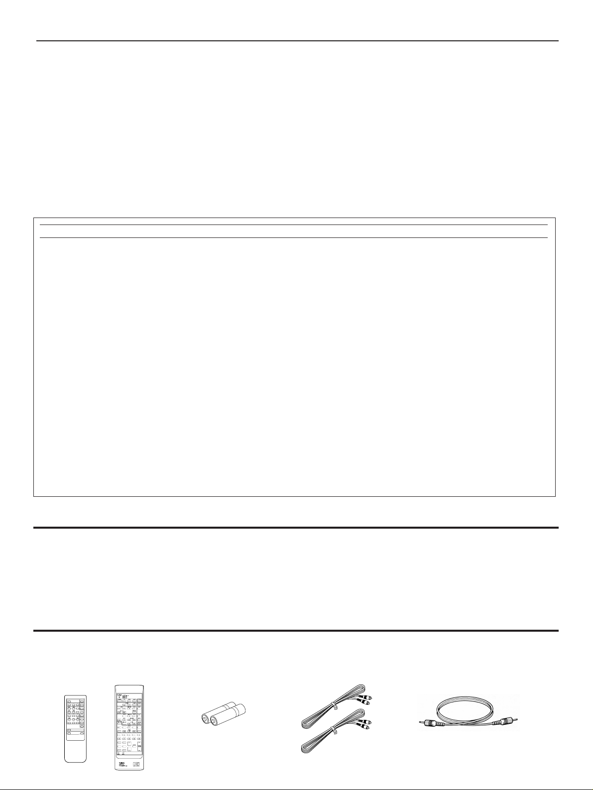
SUPPLIED ACCESSORIES
After unpacking, check that the following parts are contained.
Remote Control Transmitter. Batteries Audio Connection Cord Remote Control Cable
<CX-1><CX-2>
●
PHONO (MM/MC) Selector Switch
●
Video Signal Input/Output Capability (Including S Video
Connections) <For CX-2 only>
●
Remote Control Capability
●
REMOTE CONTROL Connector to Make the Power of
the Power Amplifier MX-1 or MX-2 Controlled by This
Unit
3
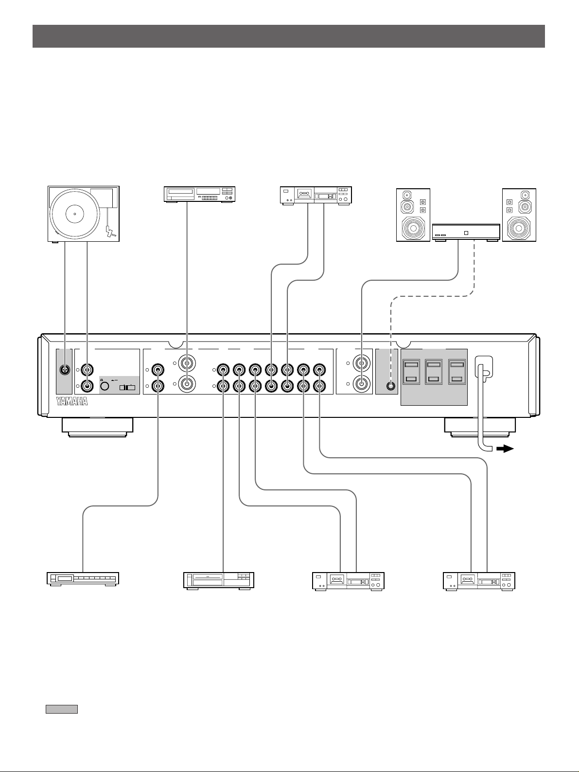
CONNECTIONS
AC OUTLETS
REMOTE
CONTROL
PRE OUT
L
R
AUX TAPE 1 TAPE 2 TAPE 3CDTUNER
L
R
L
R
L
R
PB REC OUT PB REC OUT PB REC OUT
L
R
CARTRIDGE LOADMM/MC
220ΩIK
Ω
PHONO
POWER AMP
GND
SWITCHED
I20V 60Hz
200W MAX. TOTAL
I.7A MAX. TOTAL
LINE OUT
AUDIO OUT
OUTPUT
LINE IN
LINE OUT
LINE IN
OUTPUT
LINE OUT
LINE IN
GND
OUTPUT
REMOTE
CONTROL
INPUT
●
Before attempting to make any connections to or from this unit, be sure to first switch OFF the power to this unit and to any other
components to which connections are being made.
●
When making connections between this unit and other components, be sure all connections are made correctly, that is to say L
(left) to L, R (right) to R. Also, refer to the owner’s manual for each component to be connected to this unit.
<CX-1>
Turntable
Compact disc player
Tape deck 2
Power amplifier
(U.S.A. model)
Tuner
Video cassette player,
LD player, etc.
* : Refer to “ABOUT THE ACCESSORY COMPONENTS ON THE REAR PANEL” on page 6.
* The TAPE 3 terminals gain higher Signal-to-Noise Ratio than the TAPE 1 or TAPE 2 terminals. If you will
use a Digital Compact Cassette recorder or Minidisc recorder, etc., it is recommended to connect such a
component to the TAPE 3 terminals.
4
Tape deck 3Tape deck 1
To AC outlet
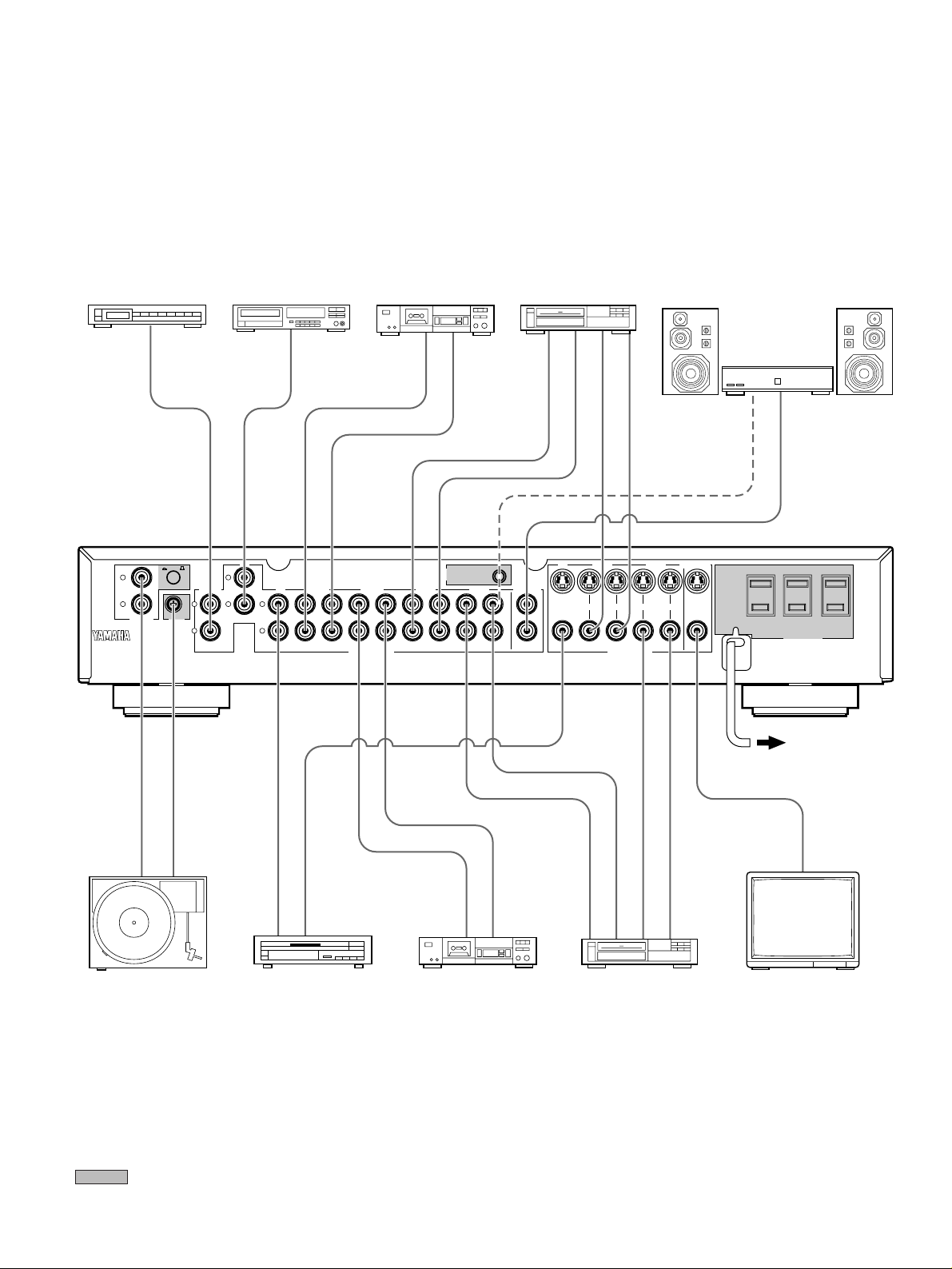
<CX-2>
Tuner
Compact disc player
OUTPUT
TUNER
CD
L
R
MC/MM
L
R L L
PHONO
GND
Tape deck 1
OUTPUT
TAPE 1 TAPE 2LD
RR
PB REC OUT PB REC OUT PB REC OUT PB REC OUT
LINE IN
LINE OUT
REMOTE
CONTROL
VCR 1 VCR 2
Video cassette
recorder 1
POWER AMP
PRE OUT
AUDIO IN
AUDIO OUT
VIDEO OUT
IN
VCR 1
IN OUT IN OUT
VIDEO IN
VIDEO SIGNALAUDIO SIGNAL
VCR 2 MON OUT
Power amplifier
INPUT
REMOTE
CONTROL
200W MAX.
TOTAL
I.7A MAX.
TOTAL
SWITCHED I20V 60Hz
AC OUTLETS
(U.S.A. model)
GND
OUTPUT
LINE OUT
LINE IN
AUDIO OUT
AUDIO IN
VIDEO OUT
VIDEO IN
Turntable
AUDIO OUT
VIDEO OUT
LD player, TV tuner, etc.
* : Refer to “ABOUT THE ACCESSORY COMPONENTS ON THE REAR PANEL” on page 6.
To AC outlet
VIDEO IN
Monitor TVTape deck 2 Video cassette recorder 2
5
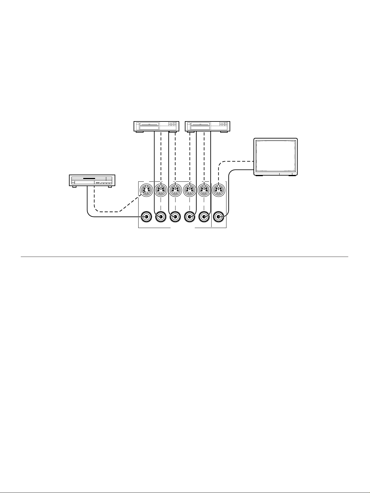
CONNECTING TO S VIDEO TERMINALS <For CX-2 only>
IN VCR 1
VIDEO SIGNAL
VCR 2 MON OUT
IN OUT IN OUT
VIDEO IN
S VIDEO IN
VIDEO
OUT
S VIDEO
OUT
VIDEO OUT
S VIDEO OUT
VIDEO IN
S VIDEO IN
VIDEO OUT
S VIDEO OUT
VIDEO IN
S VIDEO IN
If your video cassette recorder, LD player, etc. and your monitor are equipped with “S” (high-resolution) video terminals, connect
them to this unit’s S video terminals, and connect this unit’s S MON OUT terminal to the “S” video input of your monitor. Otherwise,
connect the composite video terminals from your video cassette recorder, LD player, etc. to the composite video terminals of this
unit, and connect this unit’s composite MON OUT terminal to the composite video input of your monitor.
Note
If video signals are sent to both S video input and composite video input terminals, the signals will be sent to their respective output
terminals independently.
Video cassette recorder 1 Video cassette recorder 2
Monitor TV
LD Player
S video terminals
Composite video terminals
ABOUT THE ACCESSORY COMPONENTS ON THE REAR PANEL
AC OUTLETS (SWITCHED)
(U.S.A., Canada, Europe and General models)
............................................................3 SWITCHED OUTLETS
(Australia and U.K. models)..................1 SWITCHED OUTLET
Use these to connect the power cords from your components
(except a power amplifier, integrated amplifier and receiver) to
this unit.
The maximum power (total power consumption of
components) that can be connected to the SWITCHED AC
OUTLETS is 200 watts. Strictly be careful not to exceed this
value.
The power to the SWITCHED outlets is controlled by this unit’s
POWER switch or the provided remote control transmitter’s
POWER key. These outlets will supply power to any
component whenever this unit is turned on.
PHONO switch
Select either MM or MC position depending on your PHONO
cartridge, Moving Magnet or Moving Coil type. However, if you
use a high output MC cartridge, select MM position.
CARTRIDGE LOAD switch <For CX-1 only>
Set to either impedance position (220Ω or 1 kΩ) proper for the
PHONO MC cartridge being used by your turntable.
GND terminal (For turntable use)
Connecting the ground wire of the turntable to this terminal will
normally minimize hum, but in some cases better results may
be obtained with the ground wire disconnected.
REMOTE CONTROL (POWER AMP)
connector
If you have the YAMAHA power amplifier MX-1 or MX-2,
connect this connector to the REMOTE CONTROL (PRE
AMP) connector of the power amplifier by using the provided
cable. By this connection, the power of the power amplifier is
controlled by this unit’s POWER switch or the provided remote
control transmitter’s POWER key.
After the connection is completed, keep the POWER switch of
the power amplifier pressed inward (to the ON position).
Note
If you will not connect the REMOTE CONTROL connectors of
this unit and the power amplifier, do not connect the cable to
either connector.
6
 Loading...