

Page 1

Thank you for purchasing the CS1D.
Information regarding PM1D System Software V1.41
When using the PM1D system software V1.41, please keep in mind the following supplementary explanations.
Note regarding file compatibility
●
Files that you created using system software V1.41 cannot
be loaded into a system that is running system software
V1.3 or earlier. Data that you created using system software V1.3 or earlier can be loaded into system software
V1.41. In this case, memories related to functions that were
added in 1.41 will be the same as the factory setting.
The following issues concern timecode events,
and should be read in conjunction with page
33 of the CS1D Reference Manual (Software).
●
When registering several events close together, up to five
events can be safely registered within any three second period. If you register six or more events, the sixth and subsequent events may not be recalled properly.
●
Since it takes a few seconds to chase the time code, events
are typically executed three seconds after the time code
begins running. Therefore, you must start the time code
at least three seconds before any events that you want to
execute. Note also that scenes cannot be recalled manually during this three-second period.
●
Events in the time code event list are executed only once
during each time code pass.
●
Since time code events set to INC or DEC are executed
relative to the scene number selected when the time code
first begins running, they are not affected by scene recalls
performed by other means that occur once the time code
is up and running.
●
If a scene is recalled via the time code event list while a
scene recall by some other means is being processed, the
scene recall will be executed once the first recall operation
is complete. However, if a scene recall by some other means
occurs while a scene recall via the time code event list is
being processed, the second recall may sometimes fail.
●
Time code events can be executed on the console even
without a ENGINE connected so long as TC IN SELECT
is set to either [INT GEN] or [CONSOLE]. The FADE
TIME function, however, will not operate.
●
RECALL UNDO cannot be used to undo scenes recalled
via the time code event list.
The following issues concern Mirror mode, and
should be read in conjunction with page 10 of
the CS1D Operation Manual (Start-up).
●
Reliable operation cannot be guaranteed if Engine A and
Engine B are connected differently.
●
The C port of the AI8 analog input unit cannot be used.
●
From system software V1.3 onward, functionality was
added for automatic switching from ENGINE A to ENGINE
B in mirror mode. This will automatically switch the engine from A to B when the following problems are detected.
This function automatically switches from engine A to B
if either of the following problems are detected.
1. Failure of engine A itself
2. Failure of the CONTROL I/O cable
However in order for this function to work correctly, the
following conditions must be met.
1. Engine A and engine B must both be connected correctly and functioning
2. The DIGITAL I/O cable must be connected
3. In addition, the entire system must be installed as described in the operating manual
Please also be aware of the following cautionary notes regarding the automatic engine switching function.
1. Automatic switching from engine B to engine A will
not occur.
2. If a problem occurs in the CONTROL I/O cable, switching between engines A/B will take priority over switching between connectors 1/2.
3. If the power of engine A fails during operation, it will
take approximately one second for automatic switching to occur, engine B to be selected, and audio output
to begin.
(Sound will not be interrupted if the problem is only
in the CONTROL I/O cable.)
4. If there is a problem with connections when the console is powered-on, the automatic switching may not
occur in some cases. You will need to switch manually
as needed.
Addition explanation for PREVIEW mode
●
PREVIEW mode lets you view the scene settings that have
been stored by scene memory operations on the CS1D.
The various parameters in PREVIEW mode indicate the
current state of the signal processing.
If one unit is connected to more than one engine, and you
select PREVIEW mode for the system connected to the
engine not specified for the control port, you will not be
able to operate GAIN GANG or A/B LINK.
Regarding the software version printed in the
manuals
●
All manual references to PM1D system software “version
1.0” should be read as “version 1.41”.
●
The PC connection will be denied for reasons of safety if
the “PM1D Manager for Windows” application software
is a different version than the system version of the PM1D
itself. You must use the software from the same CD-ROM
to ensure that the versions match.
Page 2
1
Thank you for purchasing the CS1D.
Additions and changes to PM1D system software V1.25
This document explains the functionality that been added or changed in PM1D system software version 1.25.
Change in how fade-time processing of each channel is defeated
Up through PM1D system software v1.2, operating a
fader while the fade time was being executed caused
fade-time processing for that channel to be cancelled.
However since it is easy to operate a fader inadvertently,
this version of the software disables this automatic cancellation, in order to prevent accidents.
If you want to cancel fade-time processing as before,
operate the fader while holding down one of the following:
•
The [SHIFT/GRAB] switch of the data entry block
•
The [SHIFT] switch in the CHANNEL SELECT section of the SELECTED INPUT CHANNEL block
•
The [SHIFT] switch in the CHANNEL SELECT section of the SELECTED OUTPUT CHANNEL block
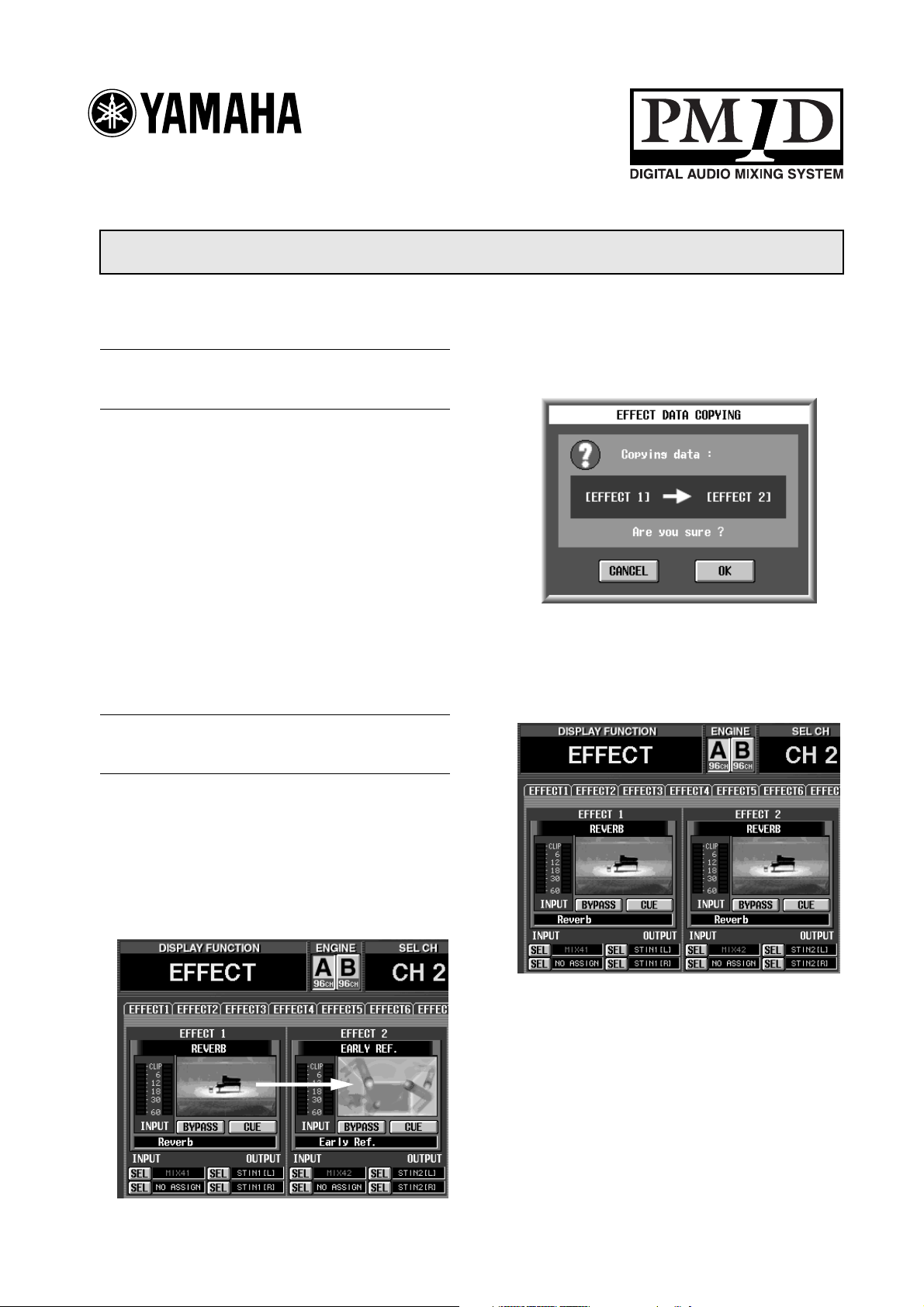
Drag & drop effect data (EFFECT ASSIGN screen)
In the EFFECT function EFFECT ASSIGN screen, you
can now use Drag & Drop to copy all settings of an
effect. Here’s how to do this.
A popup window will ask you to confirm the copy
operation.
2. To execute the copy, click the OK button. To cancel,
click the CANCEL button.
When you click the OK button, all parameters
including the effect type will be copied.
1. In the EFFECT ASSIGN screen, click the effect type
graphic for the copy source internal effect (1–8),
and drag & drop it onto the graphic for the copy
destination internal effect.
Reference pages
•
Software section, page 12
Page 3
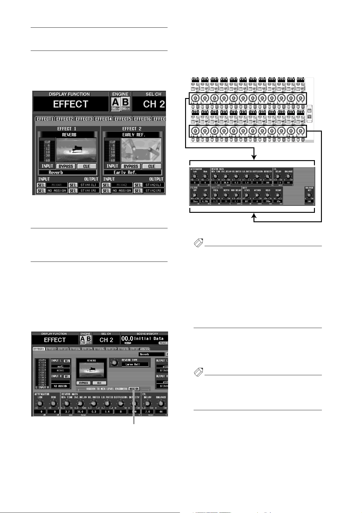
Recalling effect parameters (EFFECT ASSIGN screen)
In the EFFECT function EFFECT ASSIGN screen, you
can now access the corresponding EFFECT 1–8 screen
by clicking the graphic that indicates the effect type. This
lets you operate effect parameters more quickly.
The parameters of the currently selected effect will be
assigned to the MIX [LEVEL/BAL] encoders as
shown in the following diagram. At this time, the
MIX OUTPUT block MIX [NAME] indicator will
show the parameter name (up to four characters).
CS1D MIX OUTPUT block
PAIR
ONONONONONONONONONONONONONONONONONONONONONONON
PAIR PAIR
Encoders 1–12
PAIR
PAIR
PAIR PAIR
PAIR
PAIR PAIR
PAIR
ON
1-24
PAIR
MIX
LAYER
Reference pages
•
Software section, page 12
Using the encoders to control effect parameters (EFFECT 1–EFFECT 8 screens)
When the EFFECT function EFFECT 1–8 screens are
displayed, you can now use the encoders of the MIX
OUTPUT block to control the effect parameters. To do
this, use the following procedure to.
1. Access one of the EFFECT 1–EFFECT 8 screens.
2. Click the ASSIGN button located in the center of
the screen to turn it on.
Encoders 13–24
Hint
•When an EFFECT 1–EFFECT 8 screen is displayed,
you can hold down the [SHIFT/GRAB] switch of
the data entry block and press the MIX LAYER [124] switch or the [25-48] switch to obtain the same
result.
•The ASSIGN button on/off setting is common to
all of the EFFECT 1–EFFECT 8 screens. If you
switch between EFFECT 1–EFFECT 8 screens
when the ASSIGN button is on, the parameters of
the new screen will be assigned.
3. To return to the previous state, click the ASSIGN
button to turn it off.
The encoder functions will return to their previous
state.
Hint
The encoder functions will also return to their previous state if you access a screen other than EFFECT 1–
EFFECT 8, or if you press either the MIX LAYER [124] or [25-48] switch.
ASSIGN button
2
Reference pages
•
Basic operation, page 130
•
Software section, page 11
Page 4
1
2
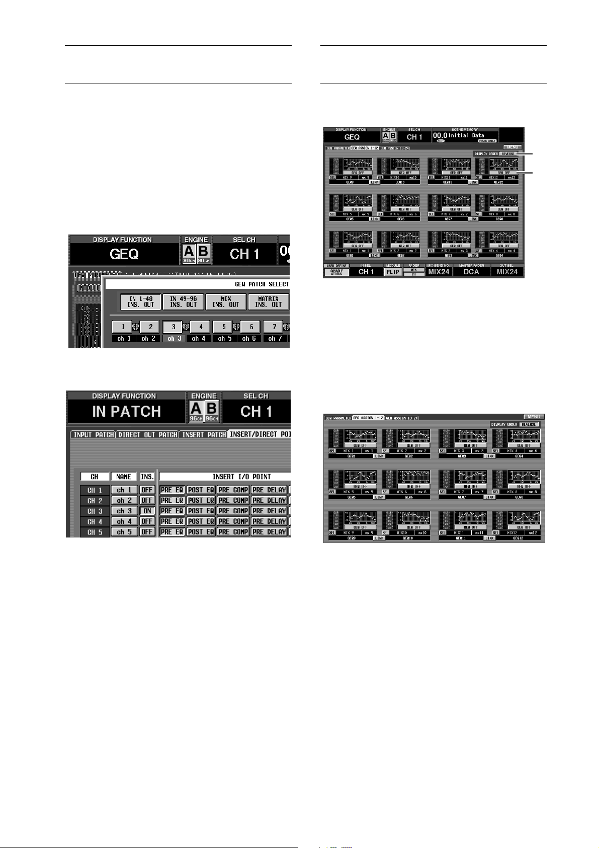
Automatic GEQ insertion (GEQ PARAMETER screen)
When you select a graphic EQ insert destination in the
GEQ function GEQ PARAMETER screen, insertion will
automatically be switched on in the corresponding
channel.
For example if you select a input channel as the GEQ
insert destination, the INS. button of the corresponding
channel will now automatically be turned on in the IN
PATCH function INSERT/DIRECT POINT screen. (It is
no longer necessary to manually turn the INS. button
on, as in earlier versions.)
“When you select an input channel as a GEQ insert
destination, ...”
Additional functions in GEQ ASSIGN 1-12 / 13-24 screens
The following buttons have been added to the GEQ
ASSIGN 1-12/13-24 screens.
2
1
GEQ ON/OFF button
This button switches each GEQ on/off.
DISPLAY ORDER REVERSE button
This button reverses the order of the GEQs in the
GEQ ASSIGN 1-12/13-24 screens. By default, the
GEQs are arranged in ascending order from bottom
to top, but will be arranged in ascending order from
top to bottom when you turn on this button.
“the INS. button of that channel will automatically be
turned on in the IN PATCH function INSERT/DIRECT
POINT screen.”
In the same way, if you select an output channel as the
insert destination, the INS. button of the corresponding
channel will automatically be turned on in the OUT
PATCH function INSERT POINT screen.
When you defeat graphic EQ insertion in the GEQ
PARAMETER screen, insert will automatically be
switched off for the corresponding channel.
Reference pages
•
Basic operation, pages 134–135
•
Software section, page 13
“Order when the DISPLAY ORDER REVERSE button is
on”
Reference pages
•
Software section, pages 16–17
3
Page 5
1
2
Meter display in the IN HA/ INSERT function / OUT INSERT function
In the IN HA/INSERT function and the OUT INSERT
function, meters are now displayed even for the effect
return, the graphic EQ output, and units to which the
talkback signal is assigned.
“Units to which an effect return is assigned”
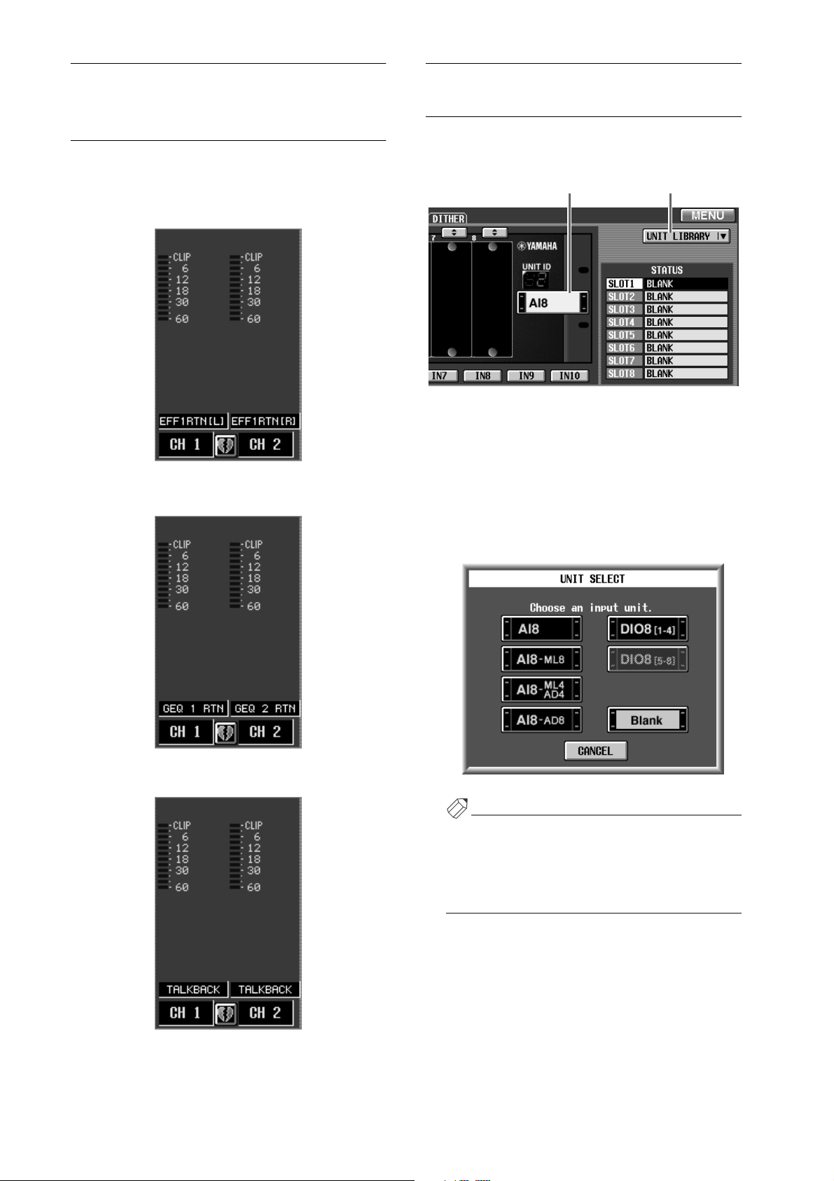
Additions and changes in the INPUT UNIT screen
The following two additions/changes have been made in
the SYS/W.CLOCK function INPUT UNIT screen.
1 2
UNIT SELECT button
This button virtually connects a unit to the jack
selected by the IN 1–IN 10 buttons. This is the same
function as the UNIT SELECT button located in the
upper right of the screen in the previous version of
the software.
When you click this button, a popup window will
appear, allowing you to select a unit.
“Units to which a graphic EQ output is assigned”
“Units to which the talkback signal is assigned”
Reference pages
•
Software section, pages 87 and 132
4
Hint
In V1.25, the above popup window lets you directly
select the model names (AI8-ML8, AI8-ML4AD4,
AI8-AD8) of currently-installed cards. If you select
one of these model names, it will not be necessary to
specify the installed card.
UNIT LIBRARY button
This button access the UNIT LIBRARY window,
where you can store/recall setting data for all units.
This button has the same function as the UNIT
LIBRARY button found in the ST IN INS/UNIT LIB
screen (IN HA/INSERT function).
Reference pages
•
Software section, pages 47–48
Page 6
1
2
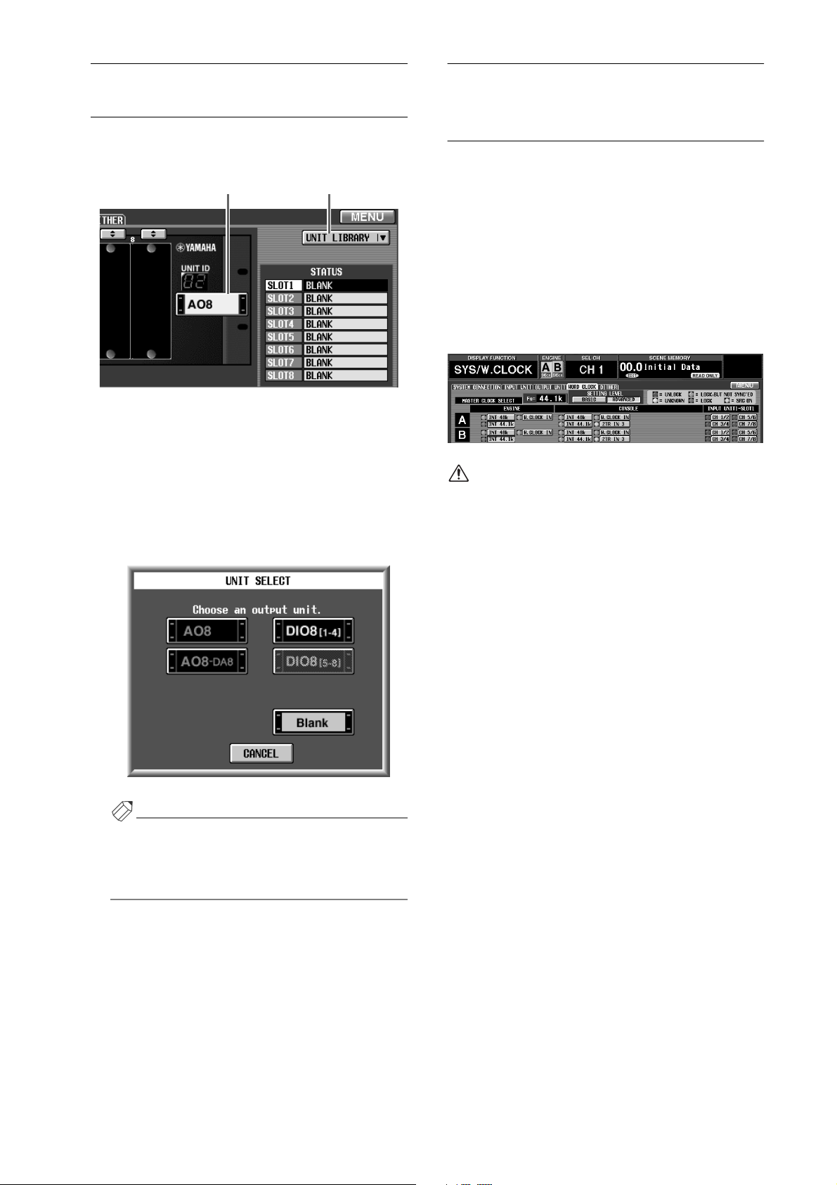
Additions and changes in the OUTPUT UNIT screen
The following two additions/changes have been made in
the SYS/W.CLOCK function OUTPUT UNIT screen.
1 2
UNIT SELECT button
This button virtually connects a unit to the jack
selected by the OUT 1–OUT 6 buttons. This is the
same function as the UNIT SELECT button located
in the upper right of the screen in the software of the
previous version.
When you click this button, a popup window will
appear, allowing you to select a unit.
Additional master clocks available for selection (WORD CLOCK screen)
In the SYS/W.CLOCK function WORD CLOCK screen,
the following three types have been added to the master
clocks that can be selected.
•
CONSOLE INT 48k
The internal clock of the CS1D (48 kHz)
•
CONSOLE INT 44.1k
The internal clock of the CS1D (44.1 kHz)
•
W.CLOCK IN
The word clock supplied to the WORD CLOCK IN
jack of the CS1D
•The above master clocks are displayed only if the
setting level is set to “ADVANCED” in the WORD
CLOCK screen.
•Some of the buttons in the WORD CLOCK
screen are arranged differently in V1.25.
In particular when using Mirror mode, selecting the
console’s INT 48k or INT 44.1k as the master clock will
allow you to construct a system that does not use an
external clock generator.
In this case, connections and settings will be as shown
on the following page.
Hint
In V1.25, the model names (A08-DA8) of cards that
are already installed can be selected directly. If you
select a model name, it will not be necessary to specify the installed card.
UNIT LIBRARY button
A button has been added that allows you to access the
UNIT LIBRARY window, where you can store/recall
setting data for all units. This button has the same
function as the UNIT LIBRARY button located in the
OUT INSERT function ST MAS INS/UNIT LIB
screen.
Reference pages
•
Software section, pages 50–51
5
Page 7
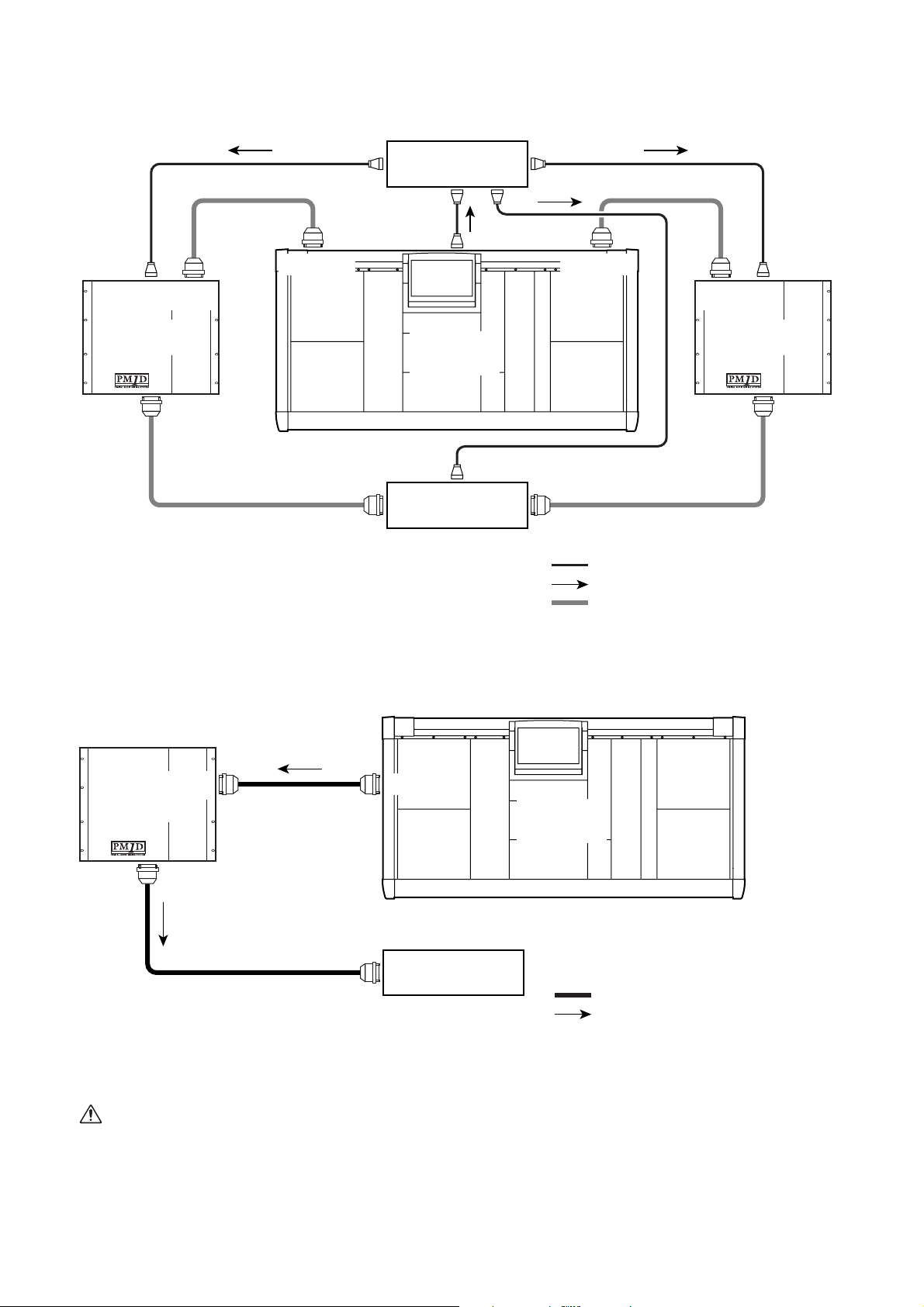
• Example setting 1
The word clock output from the console is distributed, and supplied to the various components. In this example, the
console fills the role of the clock generator.
Clock distributor
WORD
CLOCK OUT
WORD
CLOCK IN
CONSOLE
I/O
DIGITAL I/O DIGITAL I/O
CONSOLE
I/O
DSP1D (-EX)DSP1D (-EX)
CS1D
WORD
CLOCK IN
INPUT/
OUTPUT
• Word clock settings
MASTER CLOCK SELECT
Console INT 48k or INT 44.1k
WORD CLOCK INPUT SELECT
Engine: W.CLOCK IN
Each unit: W.CLOCK IN
WORD CLOCK IN
INPUT/OUTPUT INPUT/OUTPUT
Each unit
: BNC cable connection
: Word clock signal flow
: D-sub half-pitch 68-pin cable connection
INPUT/
OUTPUT
• Example setting 2
The word clock is supplied via the digital audio signal that is output from the DIGITAL I/O jack of the console. In this case,
each component that is connected by a 68-pin D-sub cable will extract the word clock from the 68-pin D-sub connector.
CONSOLE
DSP1D (-EX)
I/O
DIGITAL I/O
CS1D
INPUT/
OUTPUT
INPUT/OUTPUT
• Word clock settings
MASTER CLOCK SELECT
Console INT 48k or INT 44.1k
WORD CLOCK INPUT SELECT
Engine: 68-pin D-sub connector (AUTO and W.CLOCK IN both turned off)
Each unit: 68-pin D-sub connector (AUTO and W.CLOCK IN both turned off)
The CONSOLE INT 48k and CONSOLE INT 44.1k
settings were added so that when Mirror mode is
used, a system can be constructed without using an
external clock generator. If this is used for other
purposes, or if you have connected a device that
requires a high-precision word clock, it may not
6
Each unit
: D-sub half-pitch 68-pin cable connection
: Word clock signal flow
operate correctly. In such cases, either use an external clock generator or select INT 48k/INT 44.1k of
the engine as the master clock.
Reference pages
•
Installation, pages 24, 28–29
•
Software section, page 54
Page 8
1
2
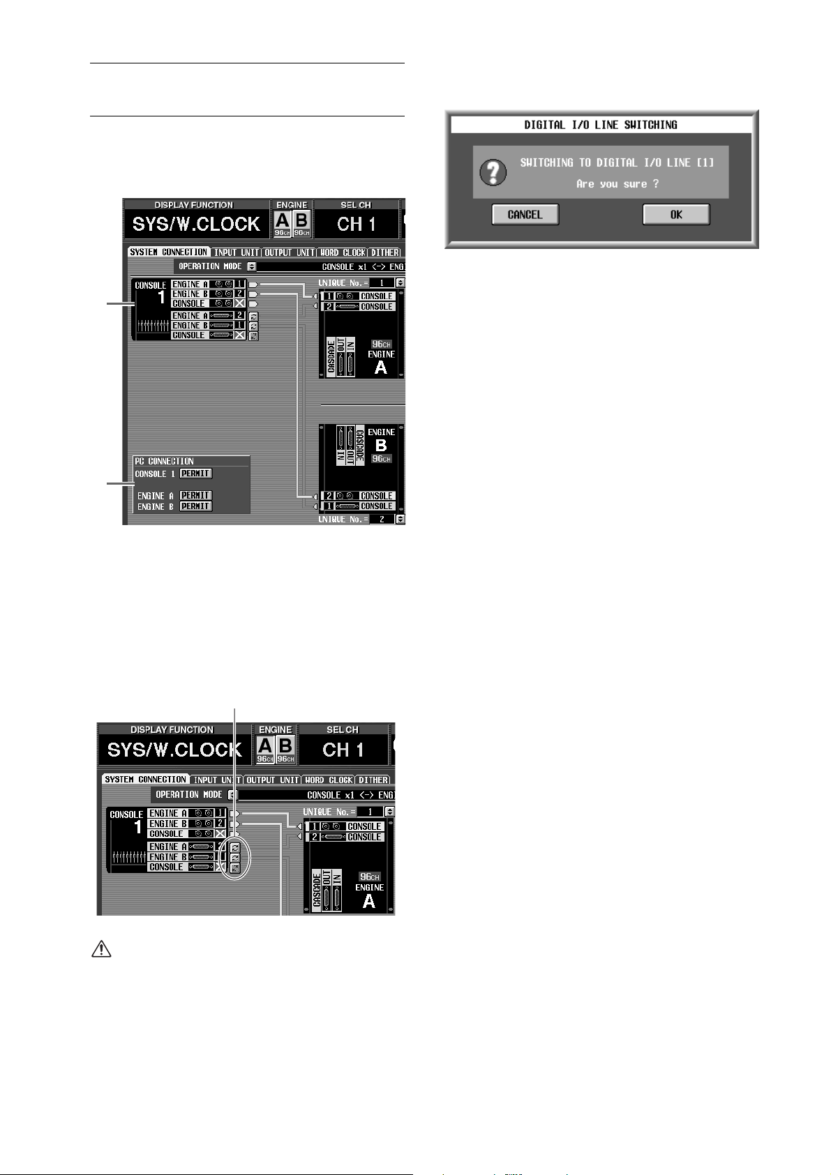
Additions and changes in the SYSTEM CONNECTION screen
The following two additions/changes have been made to
the SYS/W.CLOCK function SYSTEM CONNECTION
screen.
1
2
Manual switching of the DIGITAL I/O connectors
You can now manually switch the number (1 or 2) of
the DIGITAL I/O connector that connects the console and engine.
To do so, click the button beside the number corresponding to the DIGITAL I/O connector of the console or engine.
Click here
A switching popup window will appear, so press the
OK button to perform the switch.
Display PC connection status
The status of the connection between the console/
engine and the PC is now displayed in the PC CONNECTION section of the screen. The display has the
following significance.
•
PERMIT button
This button specifies whether to permit connection between the console/engine and the PC. When
this button is on, data transfer will be enabled
between the console/engine and PC whose serial
ports are connected to each other. For details refer
to the manual of the PC software “PM1D Manager
for Windows.”
•
OFFLINE/ONLINE
This indicates the status of connections between
the console/engine and PC. When the serial ports
are connected to each other and data can be transferred, the ONLINE symbol will be displayed. If
data cannot be transferred even though the serial
ports are connected, the OFFLINE symbol will be
displayed.
Reference pages
•
Installation, pages 23, 26, 27
•
Software section, pages 44, 45, 46
Even if you switch the number of the DIGITAL I/O
connector in the SYSTEM CONNECTION screen,
the previous connector will automatically be valid if
the appropriate signals are not being input from the
newly selected connector.
7
Page 9
1
2
1
2
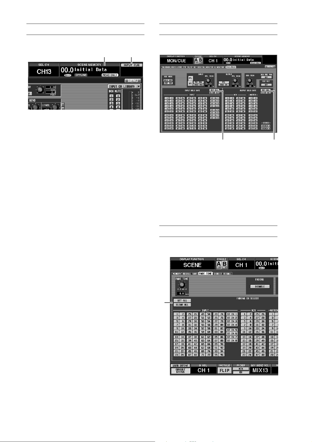
Changes in the main display
The main display has been changed as follows.
1 2
Cancel a modified scene memory number
When the scene memory title area is blinking, you
can click this area to return to the scene number that
was last stored/recalled. This is the same function as
the [CLEAR] switch of the SCENE MEMORY block.
CUE symbol
CUE symbols that indicate the section in which the
[CUE] switch is currently on have been added to the
screen. Each symbol has the following meaning.
•
INPUT CUE
This symbol will be displayed if the [CUE] switch
of an input channel is on.
•
OUTPUT CUE
This symbol will be displayed if the [CUE] switch
of an output channel is on.
•
DCA CUE
This symbol will be displayed if the [CUE] switch
of a DCA group is on.
•
SUB IN CUE
This symbol will be displayed if the SUB IN CUE
button is turned on in the MATRIX/ST function
SUB IN screen.
•
EFFECT CUE
This symbol will be displayed if the CUE button is
on in the EFFECT function EFFECT 1–EFFECT 8
screen or the EFFECT ASSIGN screen.
•
KEY IN CUE
This symbol will be displayed if the KEY IN CUE
button is on in the IN GATE/COMP function
GATE PRM screen.
Changes in the CUE/SOLO screen
The MON/CUE function CUE/SOLO screen has
changed as follows.
SET ALL/CLEAR ALL button added to INPUT
SOLO SAFE section
This button sets/clears all Solo Safe settings for the
input channels.
SET ALL/CLEAR ALL button added to OUTPUT
SOLO SAFE section
This button sets/clears all Solo Safe settings for the
output channels.
Reference pages
•
Software section, pages 74–75
Changes in the FADE TIME screen
A SET ALL button has been added to the SCENE function FADE TIME screen.
1
21
Reference pages
•
Software section, page 3
8
When you click the SET ALL button ( 1 ), the fade function will be enabled for all input channels, output channels, and DCA groups.
Reference pages
•
Software section, pages 25–26
Page 10
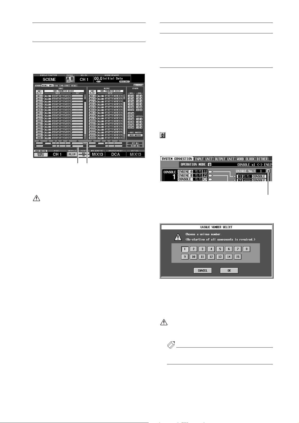
Changes in the RECALL SAFE screen
A SET ALL button and CLEAR ALL button have been
added to the SCENE function RECALL SAFE screen,
allowing Recall Safe to be set/cleared simultaneously for
all units.
12
Input/output unit sharing
Multiple PM1D systems can now share various types of
input/output unit (AI8, AO8, DIO8).
Specifying the Unique ID
If you want multiple PM1D systems to share an input/
output unit, you must first specify a Unique ID for each
engine. The Unique ID is an identifying number that
specifies the engine that will be the control source when
multiple engines (DSP1D-EX {DSP1D}) are connected
in parallel to an input/output unit. (When the PM1D
system is in the default state, engine A is set by default to
ID=1, and engine B to ID=2.)
If you want to change this ID, access the SYS/W.CLOCK
function SYSTEM CONNECTION screen, and click the
button located above the graphic of the engine.
(Alternatively, move the cursor to the button and press
the [ENTER] key.)
When you click the SET ALL button (1), all units will
be set to Recall Safe. When you click the CLEAR ALL
button (2), Recall Safe will be defeated for all units.
If the SET ALL button is on, all units (including
units that are not displayed in this screen) will be
set to Recall Safe. Please be aware that Recall Safe
will be applied to units that are not currently
patched, and to units that are patched to Insert.
Reference pages
• Basic operation, page 106
• Software section, pages 23, 24
UNIQUE No. button
When you click the button, a popup window will appear,
allowing you to select the Unique ID.
In this window, the button of the currently-selected ID
will be on. Select a new ID, and click the OK button.
The modified Unique ID will not take effect until you
restart the PM1D system. Turn off the power of all components, and then turn the power on again.
Make sure that the Unique ID of each engine does
not coincide. If the ID numbers coincide, the units
may malfunction.
Hint
Unique ID settings need to be made only if an input/
output unit is being shared by multiple engines.
9
Page 11
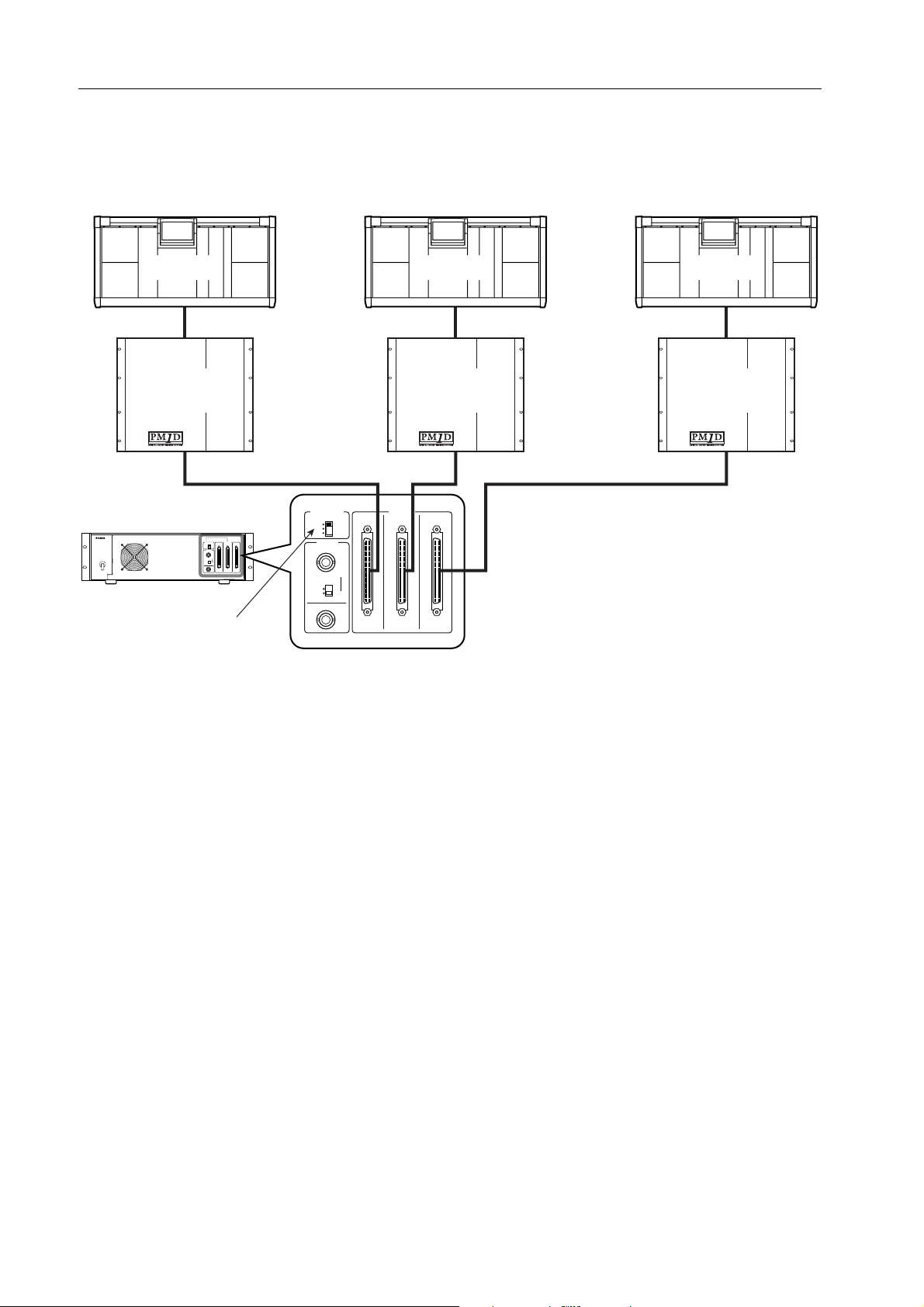
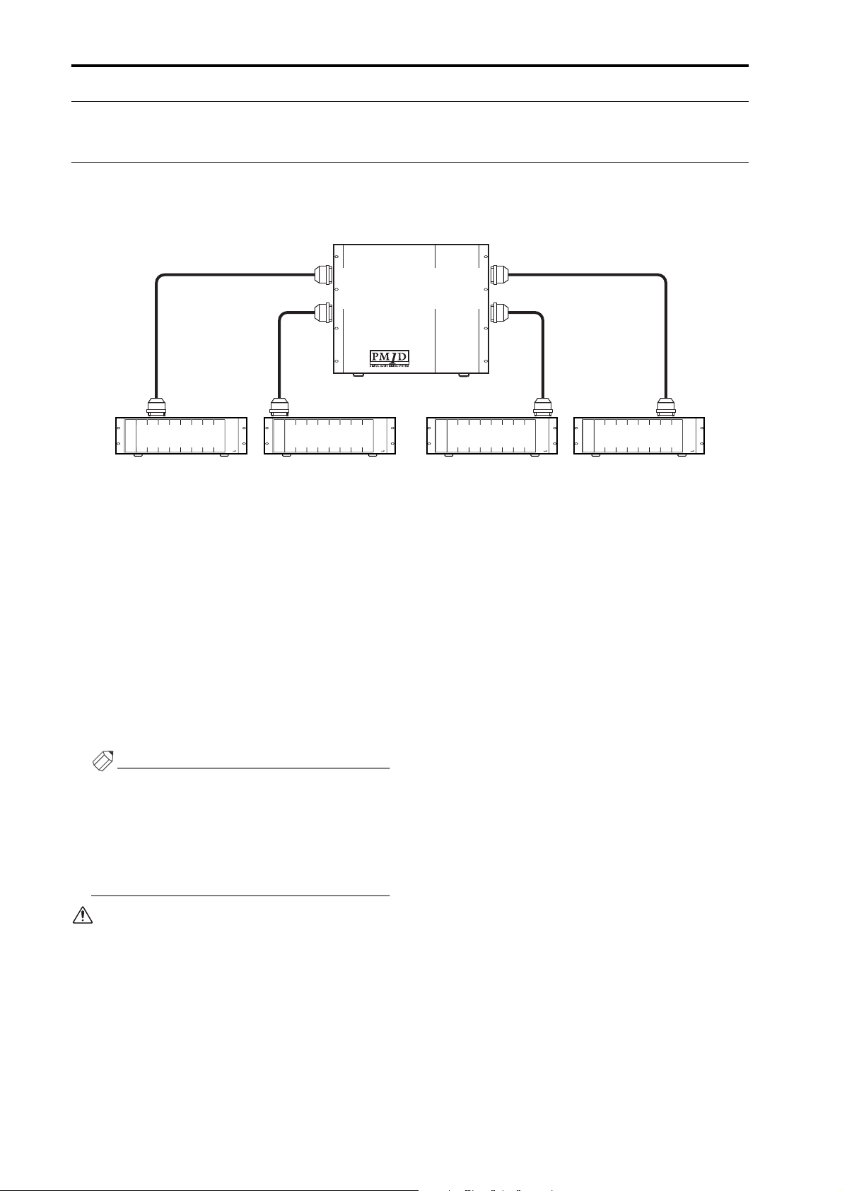
Sharing an input/output unit between multiple engines (Standard mode)
The following diagram shows example connections when sharing an AI8 input unit in Standard mode. The AI8’s OUTPUT jacks A–C are connected to engines (DSP1D) 1–3, each with a different Unique ID.
The control source engine (DSP1D) is selected by the CONTROL PORT switch of the AI8. In this diagram, the CONTROL PORT switch is set to A, so engine (DSP1D) 1 (ID=1) which is connected to the AI8’s OUTPUT jack A will be the
control source, and will adjust all parameters including gain.
CS1D-3
DSP1D-3
[UNIQUE No. : 3]
AI8 input unit
CONTROL
OUTPUT
PORT
A
CBA
B
C
WORD
CLOCK
IN
OFF
75Ω
ON
OUT
Set to A
CONTROL
PORT
A
CB A
B
C
WORD
CLOCK
IN
OFF
75Ω
ON
OUT
CBA
[UNIQUE No. : 2]
OUTPUT
Although engine (DSP1) 2 (ID=2) and engine (DSP1D)
3 (ID=3) can also recognize the AI8, they cannot adjust
its parameters. (Unit-related parameters will be shaded
in the screen.) Settings for the entire unit (such as word
clock-related settings) will also be controllable only from
engine (DSP1D) 1 (ID=1). If you want to change the
control source engine (DSP1D), change the position of
the AI8’s CONTROL PORT switch.
CS1D-2
DSP1D-2
CS1D-1
DSP1D-1
[UNIQUE No. : 1]
10
Page 12
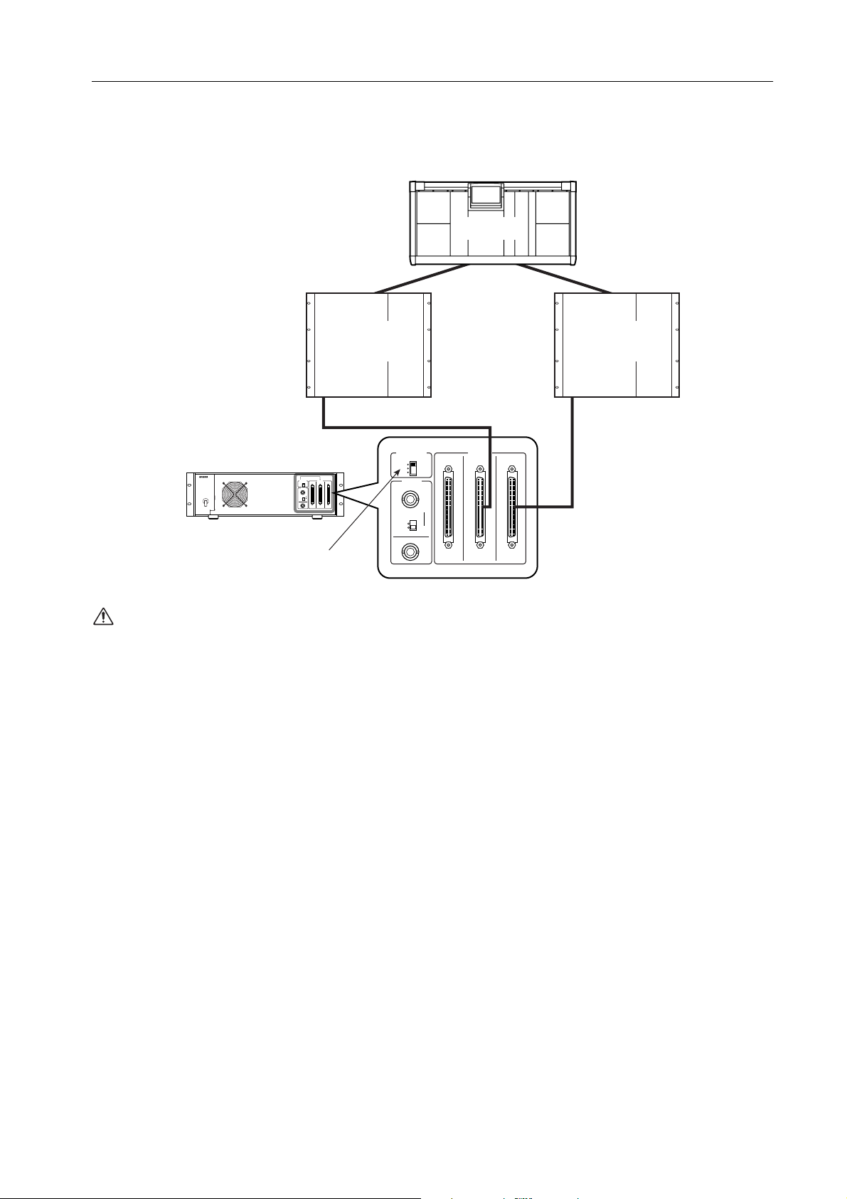
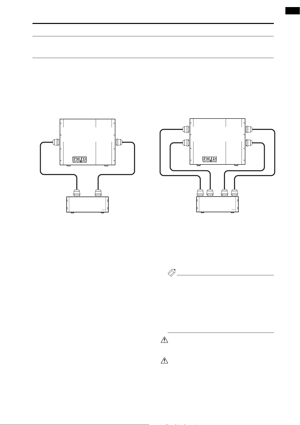
Sharing an input/output unit between multiple engines (Mirror mode)
The following diagram shows example connections when sharing an AI8 input unit in Mirror mode. The AI8’s OUTPUT
jack A is connected to engine (DSP1D-1) A, and OUTPUT jack B is connected to engine (DSP1D-2) B. In Mirror mode,
the connected jack for each unit is controlled in software. For this reason, engine A must be connected to jack A of each
unit, and engine B must be connected to jack B of each unit. (In Mirror mode, the AI8’s jack C cannot be used.)
CS1D-1
DSP1D-B
[UNIQUE No. : 2]
INPUT
1
AI8 input unit
CONTROL
OUTPUT
PORT
A
CBA
B
C
WORD
CLOCK
IN
OFF
75Ω
ON
OUT
Set to A or B
The vacant jack of a unit used in Standard mode
must not be connected to a Mirror mode system.
Doing so will cause malfunctions.
CONTROL
PORT
A
CB A
B
C
WORD
CLOCK
IN
OFF
75Ω
ON
OUT
DSP1D-A
[UNIQUE No. : 1]
INPUT
1
OUTPUT
CBA
11
Page 13
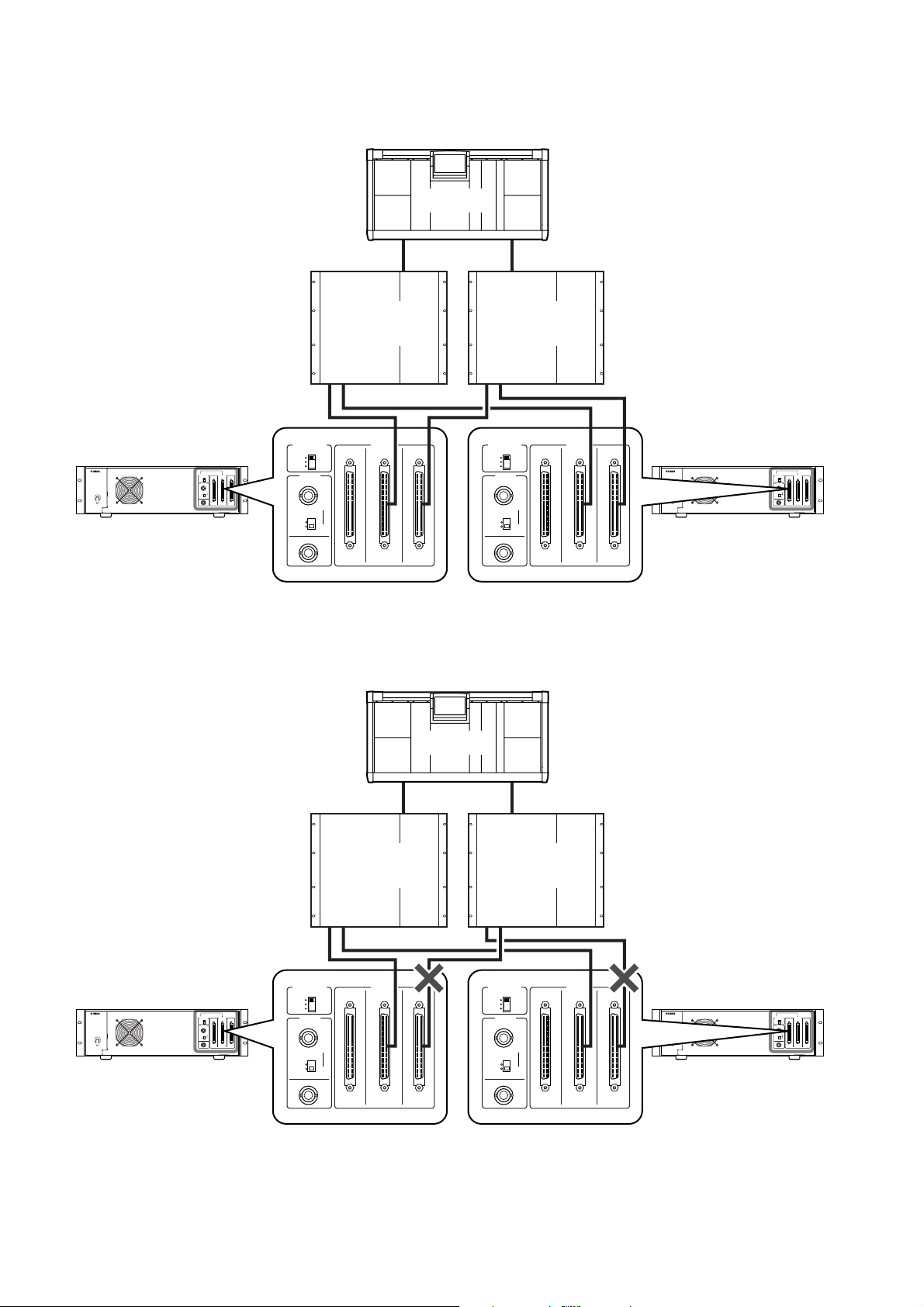
When multiple units (AI8) are shared in Mirror mode, each unit (AI8) must be connected to the identically-numbered
jack of engine (DSP1D) A/B.
Correct connections
• Mirror mode
CS1D-1
DSP1D-B
[UNIQUE No. : 2]
INPUT
1 2 3 4 5
CONTROL
PORT
OFF
A
B
C
CLOCK
ON
WORD
IN
75Ω
OUT
AI8-1 input unit AI8-2 input unit
CONTROL
OUTPUT
PORT
A
CBA
B
C
WORD
CLOCK
IN
OFF
75Ω
ON
OUT
OUTPUT
CB A
CBA
DSP1D-A
[UNIQUE No. : 1]
INPUT
1 2 3 4 5
CONTROL
PORT
A
CB A
B
C
WORD
CLOCK
CBA
IN
OFF
75Ω
ON
OUT
OUTPUT
CONTROL
PORT
A
B
C
WORD
CLOCK
OFF
ON
CBA
IN
75Ω
OUT
OUTPUT
Incorrect connections
If separate units are connected to the identically-numbered jack of engines (DSP1D) A/B as shown in the following diagram, the HA settings etc. will change when you switch between engines (DSP1D) A/B.
• Mirror mode
CS1D-1
DSP1D-B
[UNIQUE No. : 2]
INPUT
1 2 3 4 5
CONTROL
PORT
AI8-1 input unit AI8-2 input unit
CONTROL
OUTPUT
PORT
A
CBA
B
C
WORD
CLOCK
IN
OFF
75Ω
ON
OUT
A
CB A
B
C
WORD
CLOCK
IN
OFF
75Ω
ON
OUT
CBA
*1: The AI8-1’s OUTPUT jack A must be connected to the DSP1D-A’s INPUT1.
*2: The AI8-2’s OUTPUT jack A must be connected to the DSP1D-A’s INPUT2.
12
OUTPUT
DSP1D-A
[UNIQUE No. : 1]
INPUT
1 2 3 4 5
*1 *2
CONTROL
PORT
A
B
C
WORD
CLOCK
OFF
ON
IN
75Ω
OUT
OUTPUT
CB A
CBA
CONTROL
PORT
A
B
C
WORD
CLOCK
OFF
ON
CBA
IN
75Ω
OUT
OUTPUT
Page 14
Owner’s Manual
Page 15

FCC INFORMATION (U.S.A.)
1. IMPORTANT NOTICE: DO NOT MODIFY THIS UNIT! This product, when installed as indicated in the instructions contained in this manual, meets FCC
requirements. Modifications not expressly approved by Yamaha may void your authority, granted by the FCC, to use the product.
2. IMPORTANT: When connecting this product to accessories and/or another product use only high quality shielded cables. Cable/s supplied with this product MUST
be used. Follow all installation instructions. Failure to follow instructions could void your FCC authorization to use this product in the USA.
3. NOTE: This product has been tested and found to comply with the requirements listed in FCC Regulations, Part 15 for Class “B” digital devices. Compliance with
these requirements provides a reasonable level of assurance that your use of this product in a residential environment will not result in harmful interference with
other electronic devices. This equipment generates/uses radio frequencies and, if not installed and used according to the instructions found in the users manual, may
cause interference harmful to the operation of other electronic devices. Compliance with FCC regulations does not guarantee that interference will not occur in all
installations. If this product is found to be the source of interference, which can be determined by turning the unit “OFF” and “ON”, please try to eliminate the
problem by using one of the following measures: Relocate either this product or the device that is being affected by the interference. Utilize power outlets that are on
different branch (circuit breaker or fuse) circuits or install AC line filter/s. In the case of radio or TV interference, relocate/reorient the antenna. If the antenna lead-in
is 300 ohm ribbon lead, change the lead-in to coaxial type cable. If these corrective measures do not produce satisfactory results, please contact the local retailer
authorized to distribute this type of product. If you can not locate the appropriate retailer, please contact Yamaha Corporation of America, Electronic Service
Division, 6600 Orangethorpe Ave, Buena Park, CA 90620
The above statements apply ONLY to those products distributed by Yamaha Corporation of America or its subsidiaries.
ADVARSEL!
Lithiumbatteri—Eksplosionsfare ved fejlagtig
håndtering. Udskiftning må kun ske med batteri
af samme fabrikat og type. Levér det brugte
batteri tilbage til leverandoren.
VARNING
Explosionsfara vid felaktigt batteribyte. Använd
samma batterityp eller en ekvivalent typ som
rekommenderas av apparattillverkaren.
Kassera använt batteri enligt fabrikantens
instruktion.
VAROITUS
Paristo voi räjähtää, jos se on virheellisesti
asennettu. Vaihda paristo ainoastaan
laitevalmistajan suosittelemaan tyyppiin. Hävitä
käytetty paristo valmistajan ohjeiden
mukaisesti.
NEDERLAND THE NETHERLANDS
● Dit apparaat bevat een lithium batterij voor geheugen
back-up.
● Raadpleeg uw leverancier over de verwijdering van de
batterij op het moment dat u het apparaat ann het einde
van de levensduur afdankt of de volgende Yamaha Service
Afdeiing:
Yamaha Music Nederland Service Afdeiing
Kanaalweg 18-G, 3526 KL UTRECHT
Te l. 030-2828425
● This apparatus contains a lithium battery for memory
back-up.
● For the removal of the battery at the moment of the
disposal at the end of the service life please consult your
retailer or Yamaha Service Center as follows:
Yamaha Music Nederland Service Center
Address: Kanaalweg 18-G, 3526 KL
UTRECHT
Te l: 030-2828425
● Gooi de batterij niet weg, maar lever hem in als KCA.
● Do not throw away the battery. Instead, hand it in as small
chemical waste.
Page 16

Important
Read the following before operating the CS1D
•
Warnings
•
Do not allow water to enter this unit or allow the
unit to become wet. Fire or electrical shock may
result.
•
Connect this unit’s power cord only to an AC outlet
of the type stated in this Owner’s Manual or as
marked on the unit. Failure to do so is a fire and electrical shock hazard.
•
Do not place heavy objects, including this unit, on
top of the power cord. A damaged power cord is a
fire and electrical shock hazard. In particular, be
careful not to place heavy objects on a power cord
covered by a carpet.
•
Do not modify the unit. Doing so is a fire and electrical shock hazard.
•
Do not place a container with liquid or small metal
objects on top of this unit. Liquid or metal objects
inside this unit are a fire and electrical shock hazard.
Cautions
•
This unit has ventilation holes at the top and bottom
to prevent the internal temperature rising too high.
Do not block them. Blocked ventilation holes are a
fire hazard.
•
Since this device is heavy, please use an appropriate
number of people (two or more) when moving it.
•
Before moving the CS1D, you must be sure to lower
the display toward the back until it is fastened in
position.
Operating Notes
•
The digital circuits of this unit may induce a slight
noise into nearby radios and TVs. If noise occurs,
relocate the affected equipment.
Using a mobile telephone near this unit may induce
noise. If noise occurs, use the telephone away from
the unit.
•
XLR-type connectors are wired as follows: pin 1:
ground, pin 2: hot (+), and pin 3: cold (–).
•
If the message “WARNING LOW BATTERY !”
appears when you turn on this unit, contact your
dealer as soon as possible about replacing the internal data backup battery. The unit will still operate
correctly, but data other than the presets will be lost.
We recommend that you save the data on an ATAcompatible PC flash storage card before replacing the
battery.
•
The performance of components with moving contacts, such switches, rotary controls, faders, fans, and
connectors, deteriorates over time. The rate of deterioration depends on the operating environment and
is unavoidable. Consult your dealer about replacing
defective components.
•
The CS1D is cooled by fan exhaust openings located
on its rear panel. Check these regularly and use a vacuum cleaner etc. to ensure that the openings do not
become clogged with dust. Before performing this
maintenance, you must turn off the POWER switch
of the PM1D power supply unit and make sure that
the CS1D is not operating.
•
The power must be turned on/off using the POWER
switch of the PW1D power supply unit. Do not turn
the power on/off by plugging in the power cable, or
by using a power strip or circuit breaker. Doing so
may cause malfunctions.
•
Do not rapidly turn on and off the POWER switch of
the PW1D power supply unit. Doing so may cause
excessive current to damage the system. You must
allow at least five seconds to elapse between poweron and power-off.
Handling the included PM1D System Software disc
The included PM1D System Software Disc is CD-R media containing documentation and software for the PM1D.
A computer with a connected CD drive is required in order to use this documentation and software.
For details on the contents, refer to the documentation on the disc.
Please observe the following points when handling the disc.
Failure to do so may cause problems such as the recorded data being lost, the drive to malfunction, or the printed label to
become blurred.
•
Do not place the disc in locations of direct sunlight,
high temperature, or high humidity.
•
Do not touch either surface of the disc.
Hold the disc at the edges. Gently wipe dust or dirt
off of the recording surface of the disc.
ii
•
Do not wipe the disc with chemicals or detergents.
•
Do not bend or drop the disc.
•
Use an air duster or cleaner to remove dust. Vigorously rubbing the surface of the disc with a dry cloth
may scratch the disc.
Page 17

Important
•
Do not write on the disc or affix labels to it.
•
Keep water droplets or condensation off of the label
surface.
•
Yamaha Corporation makes no guarantee of a disc
that is rendered unreadable due to careless handling.
CS1D Exclusion of Certain Responsibility
Manufacturer, importer, or dealer shall not be liable for any incidental damages including personal injury or any other
damages caused by improper use or operation of the CS1D.
About the LCD display
The LCD screen built into the CS1D has the following characteristics. Please be aware that even if the following symptoms occur, this is not a malfunction or a defect.
•
Since the LCD display is manufactured with
extremely delicate technology, individual pixels may
not display correctly. (A pixel may be constantly lit or
constantly dark.)
•
The LCD screen may be affected by changes in the
ambient temperature.
•
Depending on the environment of use, you may
notice unevenness in brightness or small spots.
•
Since the LCD screen uses a cold cathode tube for a
backlight, the state of the display will gradually
change over time.
Cautions when handling the track pad
•
Place your hand and arm in a relaxed, natural position, and operate the track pad by moving your finger lightly across the surface or tapping it gently.
•
This device is designed to be operated with one finger. It will not operate in the following situations.
1) When operated by a gloved finger
2) When operated with a pen, ballpoint pen, or pencil etc.
3) When operated by two or more fingers
4) When operated with an object placed on it
•
The unit may not operate correctly if water droplets
or condensation are present on the surface, or if
operated using a soiled or sweaty finger. If condensation occurs, dry the unit thoroughly, or wipe it dry
before use.
Trademarks
ADAT MultiChannel Optical Digital Interface is a trademark and ADAT and Alesis are registered trademarks of Alesis
Corporation. Tascam Digital Interface is a trademark and Tascam and Teac are registered trademarks of Teac Corporation. Windows and Windows NT are trademarks of Microsoft Corporation. Compact Flash is a trademark of SanDisk
Corporation. Yamaha is a trademark of Yamaha Corporation. All other trademarks are the property of their respective
holders and are hereby acknowledged.
•
To avoid malfunctions, please observe the following
cautions.
1) Do not drop objects on the unit, strike it, or subject it to strong physical shock.
2) Do not spill coffee, juice, or other liquids on the
unit.
•
Do not operate the unit with a pointed metal object
such as a pen, since this will damage the unit.
•
If the surface becomes soiled, wipe it clean with a dry
cloth. If the surface is severely soiled, wipe with a
moist cloth, and dry carefully before use.
•
Do not touch the surface while the por is being
turned on.
Copyright
No part of the CS1D software or this Owner’s Manual may be reproduced or distributed in any form or by any means
without the prior written authorization of Yamaha Corporation.
© 2000 Yamaha Corporation. All rights reserved.
Yamaha website
Yamaha manual Library http://www2.yamaha.co.jp/manual/english/
http://www.yamaha.co.jp/product/proaudio/homeenglish
iii
Page 18

Operating Manual
Page 19

Operating Manual
(Start-up)
Page 20

Contents
Introduction . . . . . . . . . . . . . . . . . . . . . . . . . . . . . . . . . . . . . . . . .1
About the “CS1D Operating Manual (Start-up)” . . . . . . . . . . . . . . . . . . . . . . . . . . 1
Printing conventions in “CS1D Operating Manual (Start-up)”. . . . . . . . . . . . . . . . 1
Introducing the various components . . . . . . . . . . . . . . . . . . . . .2
Terms used in the “CS1D Operating Manual (Start-up)” . . . . . . . . . . . . . . . . . . . . 4
Connections (Standard mode). . . . . . . . . . . . . . . . . . . . . . . . . . .6
Connecting the console and engine (Standard mode) . . . . . . . . . . . . . . . . . . . . . . 6
Connecting an analog input/output unit to the engine (Standard
mode) . . . . . . . . . . . . . . . . . . . . . . . . . . . . . . . . . . . . . . . . . . . . . . . . . . . . . . . . . . . . 8
Connecting a digital input/output unit to the engine (Standard mode) . . . . . . . . 9
Connections (Mirror mode). . . . . . . . . . . . . . . . . . . . . . . . . . . .10
Connecting the console and engines (Mirror mode) . . . . . . . . . . . . . . . . . . . . . . 10
Connecting an analog input/output unit to the engines (Mirror mode) . . . . . . . 12
Connecting a digital input/output unit to the engines (Mirror mode) . . . . . . . . 13
Turning on the power and verifying the connections . . . . . . .14
Turning on the power . . . . . . . . . . . . . . . . . . . . . . . . . . . . . . . . . . . . . . . . . . . . . . 14
Checking the status of each device (Standard mode). . . . . . . . . . . . . . . . . . . . . . 15
Checking the engine (Standard mode) . . . . . . . . . . . . . . . . . . . . . . . . . . . . . . 15
Checking the analog input unit (Standard mode) . . . . . . . . . . . . . . . . . . . . . . 16
Checking the analog output unit (Standard mode) . . . . . . . . . . . . . . . . . . . . . 17
Digital input/output unit (Standard mode) . . . . . . . . . . . . . . . . . . . . . . . . . . . 17
Checking the status of each device (Mirror mode) . . . . . . . . . . . . . . . . . . . . . . . . 18
Engines (Mirror mode) . . . . . . . . . . . . . . . . . . . . . . . . . . . . . . . . . . . . . . . . . . 18
Checking the analog input unit (Mirror mode) . . . . . . . . . . . . . . . . . . . . . . . . 19
Checking the analog output unit (Mirror mode) . . . . . . . . . . . . . . . . . . . . . . . 20
Checking the digital input/output unit (Mirror mode) . . . . . . . . . . . . . . . . . . . 21
Basic settings (Standard mode). . . . . . . . . . . . . . . . . . . . . . . . .22
Selecting the operation mode (Standard mode) . . . . . . . . . . . . . . . . . . . . . . . . . 22
Setting the word clock (Standard mode) . . . . . . . . . . . . . . . . . . . . . . . . . . . . . . . 24
ii
Page 21

Contents
Basic settings (Mirror mode) . . . . . . . . . . . . . . . . . . . . . . . . . . 26
Selecting the operation mode (Mirror mode) . . . . . . . . . . . . . . . . . . . . . . . . . . . 26
Setting the word clock (Mirror mode) . . . . . . . . . . . . . . . . . . . . . . . . . . . . . . . . . 28
Checking the operation of input units . . . . . . . . . . . . . . . . . . . 30
Preparations for checking . . . . . . . . . . . . . . . . . . . . . . . . . . . . . . . . . . . . . . . . . . . 30
Connect the monitor system . . . . . . . . . . . . . . . . . . . . . . . . . . . . . . . . . . . . . . . . . 31
Connect an input source . . . . . . . . . . . . . . . . . . . . . . . . . . . . . . . . . . . . . . . . . . . . 32
Patch the input unit to an input channel . . . . . . . . . . . . . . . . . . . . . . . . . . . . . . . 33
Monitor the input signal . . . . . . . . . . . . . . . . . . . . . . . . . . . . . . . . . . . . . . . . . . . . 36
Checking the operation of an output unit . . . . . . . . . . . . . . . . 38
Preparations for checking . . . . . . . . . . . . . . . . . . . . . . . . . . . . . . . . . . . . . . . . . . . 38
Connect the monitor system . . . . . . . . . . . . . . . . . . . . . . . . . . . . . . . . . . . . . . . . . 39
Connect an input source . . . . . . . . . . . . . . . . . . . . . . . . . . . . . . . . . . . . . . . . . . . . 40
Patch the input unit to an input channel . . . . . . . . . . . . . . . . . . . . . . . . . . . . . . . 41
Patch the STEREO A channel to an output unit . . . . . . . . . . . . . . . . . . . . . . . . . . 42
Send the input signals of input channels 1/2 to the STEREO bus . . . . . . . . . . . . 44
Turn off the power. . . . . . . . . . . . . . . . . . . . . . . . . . . . . . . . . . . . . . . . . . . . . . . . . 46
iii
Page 22
Introduction
About the “CS1D Operating Manual (Start-up)”
The “CS1D Operating Manual (Start-up)” is an introductory manual that explains how to connect the various components of the PM1D system and verify that the PM1D system is operating correctly.
When starting up the PM1D system for the first time, or if you have changed the configuration of the system such as
when the PM1D system has been moved to another location and/or re-connected, we recommend that you follow the
procedure described in this manual to verify that the system is operating correctly.
•
This manual explains only the minimum operations.
For details on operating the PM1D system, please
refer to “CS1D Operating Manual (Basic operation)”
•
For details on the specifications and functionality of
the engine (DSP unit DSP1D-EX {DSP1D}) and I/O
units, please refer to the owner’s manual included
with each device.
•
For details on the function and operation of the controllers and connectors found on the top panel, rear
panel, and front panel of the console (CS1D), refer to
“CS1D Reference Manual (Hardware).”
•
For details on the software in the display screen of
the console (CS1D), refer to “CS1D Reference Manual (Software).”
Screen shots shown in this manual are taken from a
prototype. Please be aware that they may differ
slightly from the actual screens on your unit.
Printing conventions in “CS1D Operating Manual (Start-up)”
•
Differences between the 96 channel model and 48
channel model
In general, the “CS1D Operating Manual (Start-up)”
is written with the 96 channel model PM1D system
(the model with the DSP1D-EX as the engine) in
mind. Where the functionality of the 96 channel
model differs from the 48 channel model (the model
with the DSP1D as the engine), the functionality of
the 48 channel model is enclosed in curly brackets { }.
•
Standard mode and Mirror mode
The PM1D system has two operation modes (elements that determine system structure and connection method); “Standard mode” in which one
console is connected to one engine, and “Mirror”
mode in which one console is connected to two
engines of which only one is used.
Be aware that the mode used by the PM1D system
will depend not only on the number of engines, but
also on the type of connections and on the internal
settings.
Explanations that apply only to Standard mode will
be indicated by the following symbol.
DSP
x1x1
The PM1D system version 1.0 does not support any
other operation mode (i.e., other than Mirror
mode) in which two engines are used.
•
Distinguishing between the controls of the CS1D
and the on-screen knobs/buttons
Names of controls (switches, encoders, faders) on the
top panel, rear panel, and front panel of the CS1D
are enclosed in square brackets [ ] in order to distinguish them from the knobs and buttons etc. that are
displayed in the screen.
Example : Tu rn on the [TO ST] switch.
(This indicates an operation on the top panel of the
CS1D.)
Example : Click the BASIC button.
(This indicates an operation in the display screen.)
•
Va r ious icons
The following icon is used to call your attention to
various tips for operation or to reference pages.
Hint
The following icon is used to indicate particularly
important items or operations that you must be
aware of.
Explanations that apply only to
indicated by the following symbol.
DSP
x2x2
Mirror mode will be
1
Page 23
Introducing the various components
The PM1D system consists of the following types of components. (The components that are actually included will differ
depending on your system.)
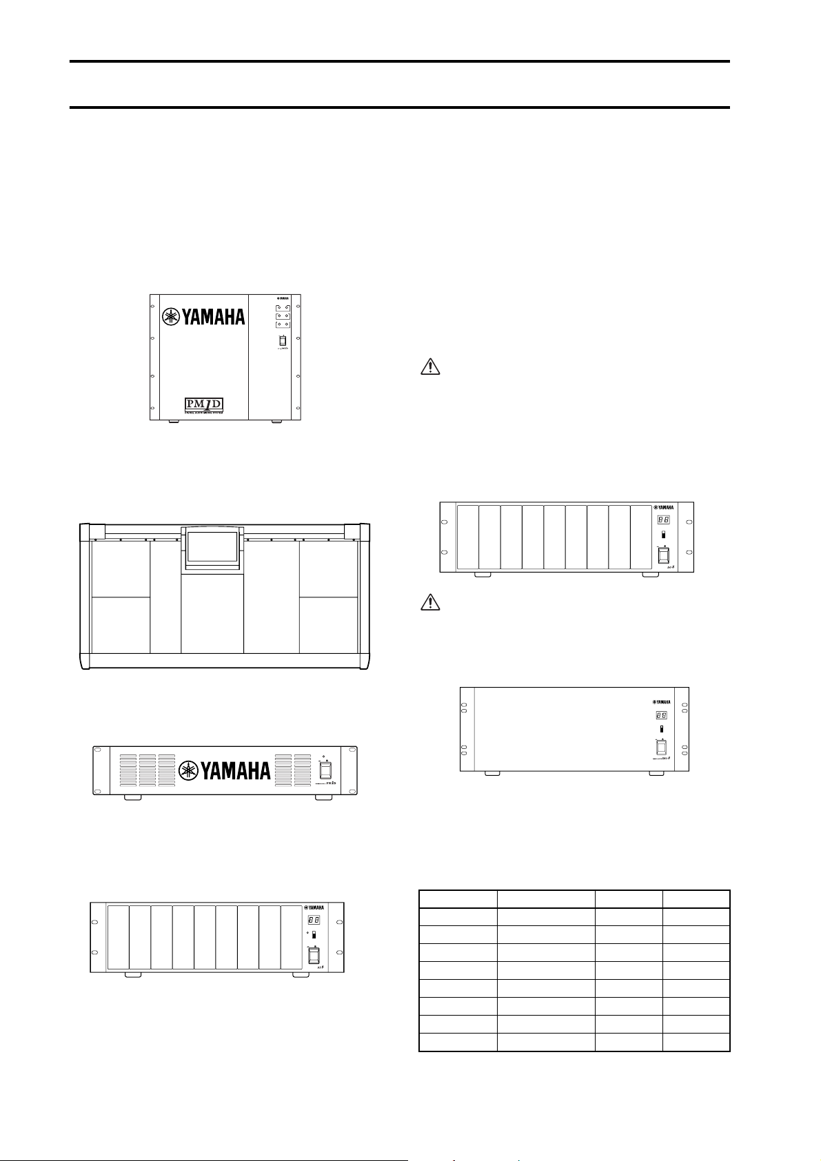
Engine (DSP1D-EX {DSP1D})
This is the DSP unit that performs the majority of the
audio processing in the PM1D system, such as audio signal input/output, mixing, and effects. There are two
models of engine: the 96 channel DSP1D-EX , and the
48 channel DSP1D .
ENGINE ID
A B
CONTROL I/O
1 2
INPUT
CONFIGURATION
48CH 96CH
POWER
ON/ OFF
Console (CS1D)
The mixing operations, scene memory/library operations, and various editing operations of the PM1D system are performed from this console.
The following models of AI8 are available, depending on
the type of analog input cards that are installed.
•
AI8-ML8
A unit with eight mic/line input cards installed
•
AI8-AD8
A unit with eight AD cards installed
•
AI8-ML4AD4
A unit with four mic/line input cards + four AD
cards installed
Cards can be installed in the AI8 only by a Yamaha
service engineer. The user must never attempt to
install a card himself.
Analog output unit (AO8)
This is an output unit that outputs analog audio signals
from the engine, and can accommodate eight DA cards
(LMY4-DA).
1234567
8
OUTPUT UNIT NO.
INPUT SELECTOR
A
B
POWER
ON/ OFF
ANALOG OUTPUT BOX
Power supply (PW1D)
This power supply provides power to the console.
POWER
ON OFF
Analog input unit (AI8)
This is an input unit that inputs analog audio signals to
the engine, and can accommodate up to eight analog
input cards.
12345678
INPUT UNIT NO.
PHANTOM MASTER
ON
OFF
POWER
ON/ OFF
ANALOG INPUT BOX
+48V
The following types of cards can be installed in the AI8.
•
Mic/line input card (LMY2-ML)
•
AD card (LMY4-AD)
Cards can be installed in the AO8 only by a Yamaha
service engineer. The user must never attempt to
install a card himself.
Digital input/output unit (DIO8)
I/O UNIT ID
PORT B SELECTOR
5-8
1-4
POWER
ON/ OFF
This unit performs input/output of ADAT, Tascam, and
AES/EBU format digital audio signals and input/output
of analog audio signals to and from the engine of the
PM1D system. Each DIO8 unit can accommodate up to
eight digital I/O cards or analog I/O cards.
The following types of card can be installed.
Card Format Input Output
MY8-TD TASCAM 8 IN 8 OUT
MY8-AT ADAT 8 IN 8 OUT
MY8-AE AES/EBU 8 IN 8 OUT
MY8-AD ANALOG IN 8 IN —
MY4-AD ANALOG IN 4 IN —
MY4-DA ANALOG OUT — 4 OUT
AP8AD* ANALOG IN 8 IN —
AP8DA*
*: Manufactured by Apogee Corporation
ANALOG OUT — 8 OUT
* As of September 1, 2000
2
Page 24
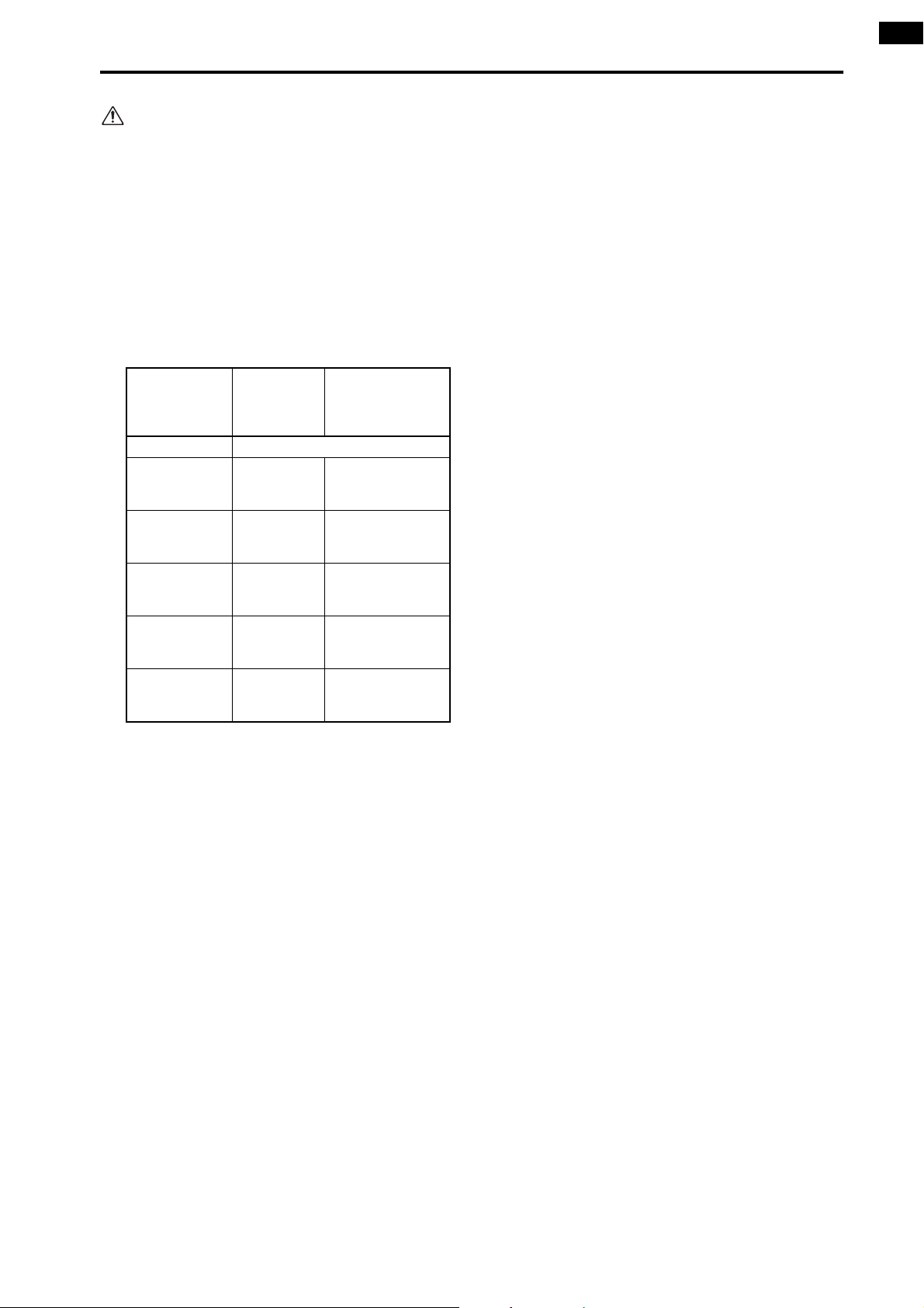
It is not possible to install and use a total of five or
more AP8AD/AP8DA cards. Also, if you are using
AP8AD/AP8DA cards simultaneously with MY8AD/MY4-AD/MY4-DA cards, there are restrictions
on the number of cards, as described below. Never
exceed the allowable number of cards, since
attempting to use a greater number of cards than
allowed may damage the DIO8 due to excessive
current. If you are not using AP8AD or AP8DA
cards, or if you are using AP8AD or AP8DA cards
simultaneously with an MY8-TD/MY8-AT/MY8AE card, there is no limitation on the number of
MY8-TD/MY8-AT/MY8-AE cards that can be used.
Introducing the various components
[AP8AD] +
[AP8DA] cards
used
Total 0 cards Up to a total of 8 cards
Total 1 card Up to 6 cards
Total 2 cards Up to 4 cards
Total 3 cards Up to 2 cards
Total 4 card Up to 1 card
Total 5 or more
cards cannot
be used
[MY8-AD] +
[MY4-AD] +
[MY4-DA]
cards used
——
[MY8-TD] +
[MY8-AT] +
[MY8-AE] cards
used
Up to the number
of vacant DIO8
slots
Up to the number
of vacant DIO8
slots
Up to the number
of vacant DIO8
slots
Up to the number
of vacant DIO8
slots
3
Page 25
CS1D Operating Manual (Start-up)
Terms used in the “CS1D Operating Manual (Start-up)”
Of the specialized terms used in operating the CS1D, this section will explain the terms that appear in “CS1D Operating
Manual (Start-up).” For a more detailed explanation of terms, refer to “CS1D Operating Manual (Basic Operation).”
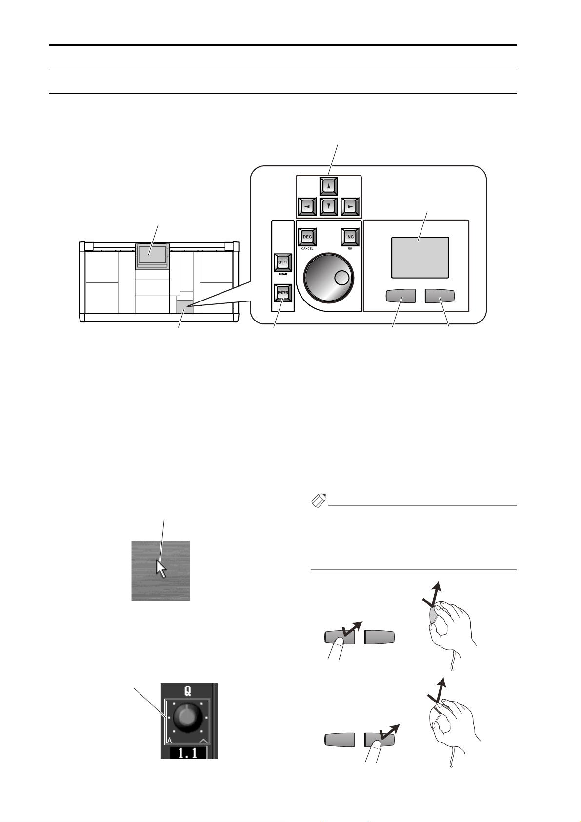
[CURSOR] switches
Track pad
Display
Data entry block
•
Display
This refers to the LCD display located in the upper
center of the CS1D console. When you wish to
change an internal setting of the CS1D, you can recall
the appropriate screen in the display, and use the
buttons or knobs in the display to edit the setting.
•
Pointer
The arrow shown in the display is called the
“pointer,” and is used to select the object that you
wish to modify. You can move the pointer by pressing
your finger on the track pad (located in the data
entry block) and dragging it up/down/left/right.
Pointer
Right switch
•
Left switch[ENTER] switches
Click
“Click” refers to the action of placing the pointer on
a specific item in the display, and pressing the left or
right switch of the track pad (located in the data
entry block). This action is used to turn an on-screen
button on/off, or to move the cursor to a specific
item.
Using the [CURSOR] switches (located in the data
entry block) to move the cursor to a specific item and
then pressing the [ENTER] switch will have the same
result as clicking on that item.
Hint
As alternative ways to perform this action, you can
use a mouse connected to the MOUSE connector of
the CS1D, or use the arrow keys and ENTER key of a
keyboard connected to the KEYBOARD connector of
the CS1D.
Mouse left click
•
Cursor
The red frame shown in the display is called the “cursor.” An on-screen item will be enclosed by the cursor to indicate that this item is selected for
modification.
Cursor
4
Left switch
Click
Mouse right click
Right switch
Click
Page 26
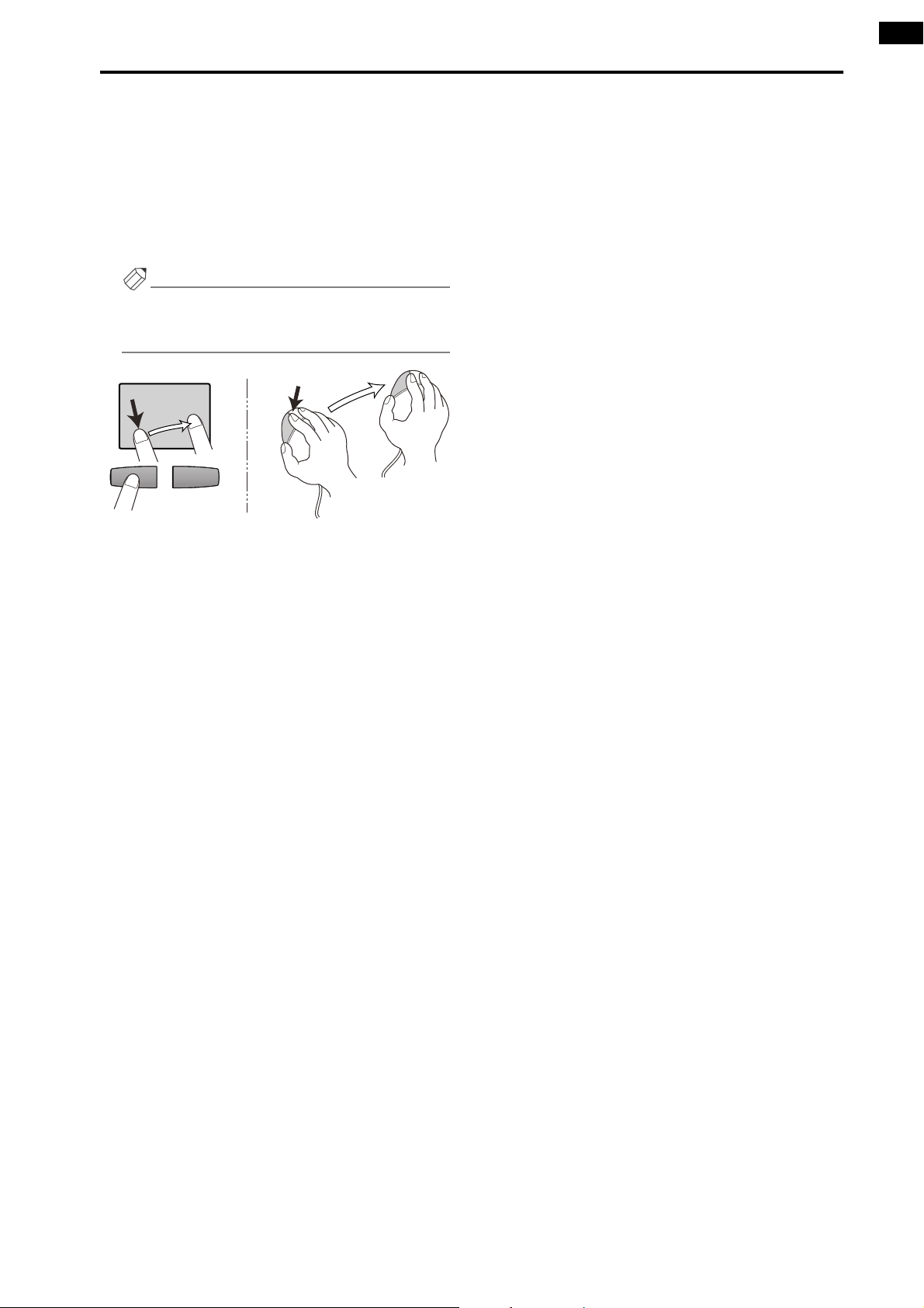
•
Drag
“Drag” refers to the action of placing the pointer
over a specific object on the screen, and holding
down the left or right switch while you slide your finger left/right/up/down across the track pad.
This action is used to continuously adjust a knob or
slider in the screen, or to move a specific item to
another location.
Hint
As an alternative way to perform this action, you can
use a mouse connected to the MOUSE connector of
the CS1D.
Introducing the various components
Track pad
Drag
While pressing
Drag
Mouse
5
Page 27
1
Connections (Standard mode)
DSP
x1x1
This section explains connections for Standard mode, in which one console (CS1D) is connected to one engine (DSP1DEX {DSP1D}).
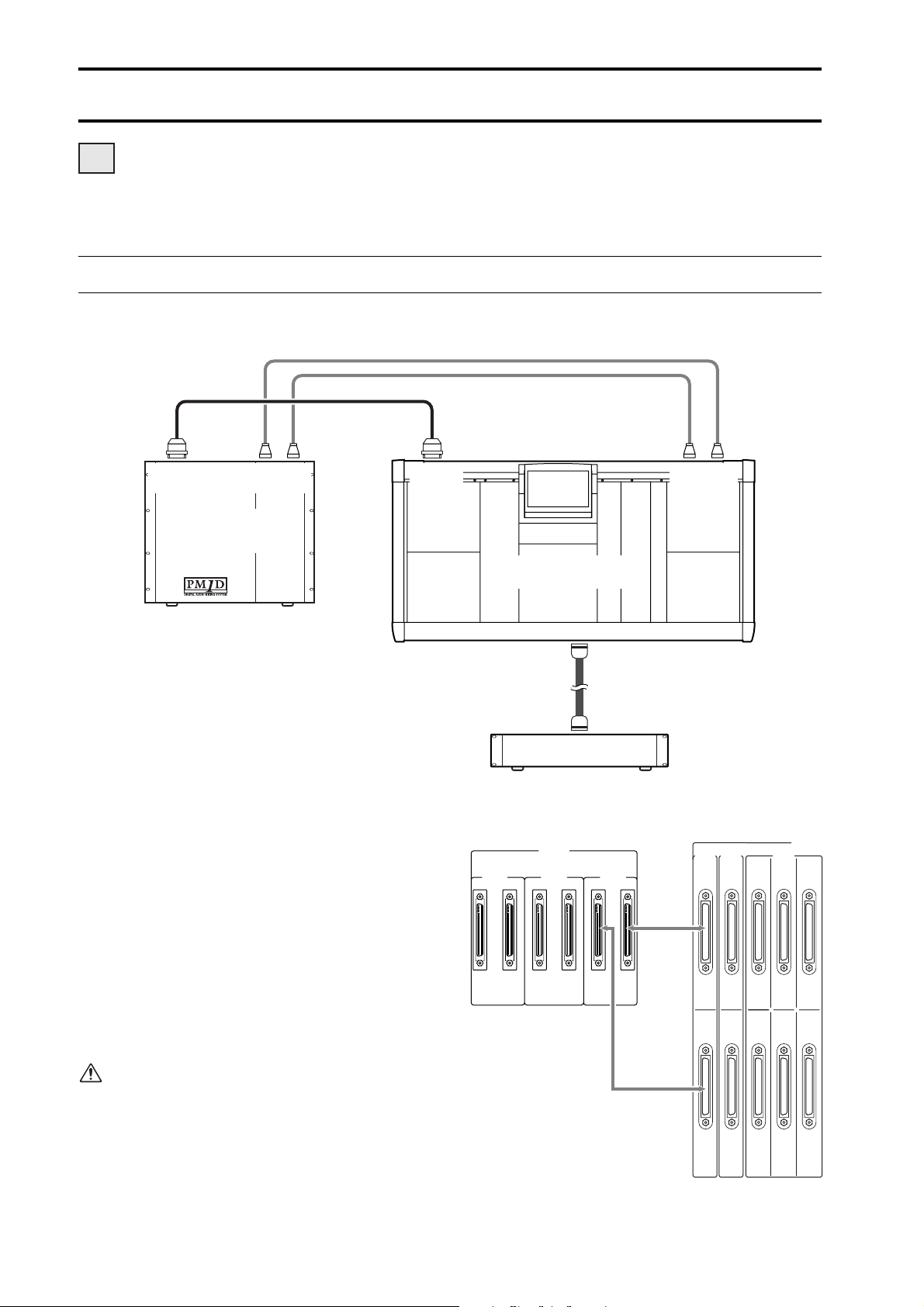
Connecting the console and engine (Standard mode)
The following diagram shows typical connections between the console and engine for Standard mode.
ENGINE A
IN OUT
CONSOLE
I/O
CONTROL
I/O
DIGITAL
ENGINE A
(DSP1D-EX{DSP1D})
Digital input/output connections
Use the included D-sub half pitch 68 pin cable to
connect the DIGITAL I/O ENGINE A connector of
the console to the CONSOLE I/O connector of the
engine.
These connectors transmit and receive multi-channel
digital audio signals.
The console and engine each have two identical digital input/output connectors, numbered 1 and 2.
These two sets of connectors are completely identical, and the system will operate normally if just one
set is connected. However, you may connect both 1
and 2 so that one of them can be used as a backup.
You must connect the identically-numbered con
nectors of the console and engine to each other. If
differently-numbered connectors are connected to
each other, the system will not function correctly.
I/O
1
ENGINE A
IN OUT
CONTROL
2
I/O
CONSOLE (CS1D)
DC POWER
INPUT A
3
POWER SUPPLY (PW1D)
This method of connection is recommended for
most cases.
DIGITAL I/O
CONSOLE
2
ENGINE B
1 2121
Console (CS1D)
ENGINE A
CONSOLE
CASCADE
I/O
1IN531
2 OUT 6 4 2
DIGITAL I/O
OUTPUT
6
Engine
(DSP1D-EX {DSP1D})
Page 28
Connections (Standard mode)
22
22
Hint
If both digital input/output connectors 1 and 2 are
connected, connector 1 will be given priority when
the power is turned on.
If the word clock stops being supplied from either
connector 1 or 2 (whichever is the currently-used
connector), the receiving device will automatically
switch to the other connector.
•
Use only Yamaha-manufactured D-sub half pitch 68
pin cables to connect the digital input/output connectors. Operation cannot be guaranteed if any other
cables are used.
•
If you need a cable of a different length than the
included D-sub half pitch 68 pin cable, please contact your dealer.
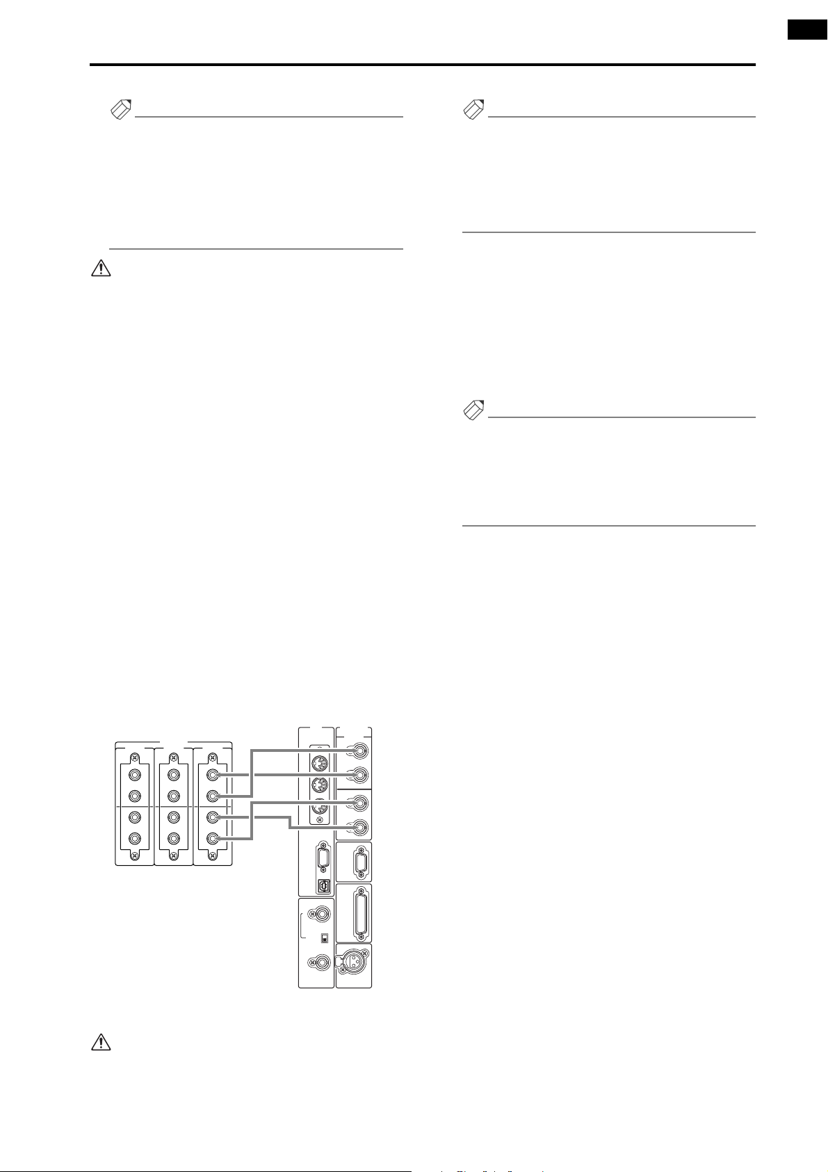
Control input/output connections
Use BNC cables (50
Ω
) to connect the CONTROL I/
O ENGINE A IN connector of the console to the
CONTROL I/O OUT connector of the engine, and
the CONTROL I/O ENGINE A OUT connector of
the console to the CONTROL I/O IN connector of
the engine.
These connectors transmit and receive control signals between the console and engine.
The console and engine each have two identical sets
of connectors, numbered 1 and 2.
These two sets of connectors are completely identical, and the system will operate normally if just one
set is connected. However, you may connect both 1
and 2 so that one of them can be used as a backup.
This method of connection is recommended for
most cases.
MIDI CONTROL I/O
IN
USB
WORD CLOCK
IN
OFF
75Ω
ON
CONSOLE
1
IN
OUT
2
IN
OUT
REMOTE
RS-422
GPI
TIME CODE IN
CONTROL I/O
CONSOLE ENGINE B ENGINE A
1
IN
OUT
IN
OUT
1
IN
OUT
2
2
IN
OUT
Console (CS1D)
1
IN
OUT
2
IN
OUT
OUT
THRU
PC
CONTROL
RS-232-C
OUT
Hint
If both control input/output connectors 1 and 2 are
connected, connector 1 will be given priority when
the power is turned on.
If the currently-used control output connector stops
functioning correctly, the receiving device will automatically switch to the other connector.
Power supply connections
Use the included special cable to connect the DC
POWER INPUT connector of the console to the DC
OUTPUT connector of the PW1D power supply.
The rear panel of the console has two DC POWER
INPUT connectors, A and B.
If you are using only one power supply, you may connect it to either DC POWER INPUT connector.
Hint
You can also connect two power supplies to the two
DC POWER INPUT connectors A and B. If this connection method is used, the PM1D system will continue to operate even if one of the power supplies
should unexpectedly fail, since the other power supply will continue to supply power to the system.
2
Engine
(DSP1D-EX {DSP1D})
You must connect the identically-numbered con
nectors of the console and engine to each other. If
differently-numbered connectors are connected to
each other, the system will not function correctly.
-
3
7
Page 29
CS1D Operating Manual (Start-up)
Connecting an analog input/output unit to the engine (Standard mode)
The following diagram shows a common way of making connections between the engine and analog input/output units
for Standard mode.
12
INPUT 2
INPUT 1
ENGINE A
(DSP1D-EX{DSP1D})
OUTPUT 2
OUTPUT 1
INPUT A INPUT AOUTPUT A OUTPUT A
AI8 (ID=2) AI8 (ID=1) AO8 (ID=1) AO8 (ID=2)
ANALOG INPUT BOXANALOG INPUT BOX
CONTROL PORT
Switch = A
CONTROL PORT
Switch = A
Analog input unit AI8 connection
Connect the OUTPUT A connector of the AI8 analog
input unit to one of the INPUT 1–INPUT 10 connectors of the engine. Set the CONTROL PORT
switch (located on the rear panel of the AI8) to the A
position.
Analog output unit AO8 connection
Connect the INPUT A connector of the AO8 analog
output unit to one of the OUTPUT 1–OUTPUT 6
connectors of the engine. Set the INPUT SELECTOR
switch (located on the front panel of the AO8) to the
A position.
Hint
An AI8 analog input unit can be connected to any
INPUT connector of the engine, and the number of
that INPUT connector will be the ID number of that
unit. Similarly, an AO8 analog output unit can be
connected to any OUTPUT connector of the engine,
and the number of that OUTPUT connector will be
the ID number of that unit.
INPUT SELECTOR
Switch = A
ANALOG OUTPUT BOX ANALOG OUTPUT BOX
INPUT SELECTOR
Switch = A
Be careful not to connect inputs and outputs in
reverse. If such a connection is made, the unit will
not be recognized and cannot be controlled.
8
1
2
Page 30
Connections (Standard mode)
Connecting a digital input/output unit to the engine (Standard mode)
When connecting a DIO8 digital input/output unit to the engine in Standard mode, the method will depend on whether
you use only slots 1–4 (of the DIO8’s slots 1–8) or slots 1–4 as well as slots 5–8.
If input/output cards are installed only in DIO8
slots 1–4
The following diagram shows example connections
for when input/output cards are connected only to
slots 1–4 of the DIO8.
ENGINE A
INPUT 1
Connect the OUTPUT A connector of the digital
input/output unit to one of the INPUT 1–10 connectors of the engine, and connect the INPUT A connector of the digital input/output unit to one of the
OUTPUT 1–6 connectors of the engine. In this case,
set the PORT B SELECTOR switch (located on the
front panel of the DIO8) to the 5-8 position.
(DSP1D-EX{DSP1D})
OUTPUT A INPUT A
DIO8 (ID=1)
PORT B SELECTOR=5–8
OUTPUT 1
If input/output cards are also installed in DIO8
slots 5–8
The following diagram shows example connections
for when input/output cards are installed in DIO8
slots 1–4 and also in slots 5–8.
INPUT 1
ENGINE A
INPUT 2
Connect the OUTPUT connectors A/B of the digital
input/output unit to the INPUT 1–10 connectors of
the engine, and connect the INPUT connectors A/B
of the digital input/output unit to OUTPUT 1–6
connectors of the engine. In this case, set the PORT B
SELECTOR switch (located on the front panel of the
DIO8) to the 5-8 position.
(DSP1D-EX{DSP1D})
BBAA
OUTPUT INPUT
DIO8 (ID=1)
PORT B SELECTOR=5–8
OUTPUT 2
OUTPUT 1
Hint
The DIO8 digital input/output unit can be connected to any INPUT connector/OUTPUT connector of the engine. The DIO8 will automatically select
a control connector according to the status of connections, and the connector number of the engine
connected to that connector will be displayed in the
LED display as the unit ID. In the example shown
above, the INPUT 1 connector number is the unit ID
number.
Be careful not to connect inputs and outputs in
reverse. If such a connection is made, the unit will
not be recognized and cannot be controlled.
When using an MY8-AT card to handle ADAT for
mat signals, synchronization may tend to be lost
easily, depending on the device that is connected.
1
2
For more reliable synchronization, we recommend
that the word clock for the combination of digital
audio equipment you are using be taken from other
than the ADAT format connector.
-
9
Page 31

Connections (Mirror mode)
DSP
x2x2
This section explains connections for Mirror mode, in which one console (CS1D) is connected to two engines (DSP1DEX {DSP1D}).
Connecting the console and engines (Mirror mode)
The following diagram shows typical connections between the console and engines for Mirror mode.
12
CONSOLE
I/O
ENGINE A ENGINE B
IN OUT IN OUT
CONTROL
I/O
DIGITAL
I/O
ENGINE A
(DSP1D-EX{DSP1D})
CONSOLE (CS1D)
WORD
CLOCK IN
WORD
CLOCK IN
DC POWER
INPUT A
POWER SUPPLY (PW1D)
Clock Generator
Digital input/output connections
Use the included D-sub half pitch 68 pin cables to
connect the DIGITAL I/O ENGINE A connector of
the console to the CONSOLE I/O connector of engine
A, and the DIGITAL I/O ENGINE B connector of the
console to the CONSOLE I/O connector of engine B.
These connectors transmit and receive multi-channel
digital audio signals.
ENGINE A ENGINE B
IN OUT
CONTROL
I/O
CONSOLE
I/O
IN OUT
CONTROL
ENGINE B
(DSP1D-EX{DSP1D})
WORD
CLOCK IN
3
4
set is connected. However, you may connect both 1
and 2 so that one of them can be used as a backup.
This method of connection is recommended for
most cases.
CONSOLE
CASCADE
I/O
1IN5
2
CONSOLE
DIGITAL I/O
ENGINE B
1 2121
ENGINE A
I/O
CONSOLE
CASCADE
I/O
1IN5
•
Use only Yamaha-manufactured D-sub half pitch 68
pin cables to connect the digital input/output connectors. Operation cannot be guaranteed if any other
cables are used.
•
If you need cables of a different length than the
included D-sub half pitch 68 pin cables, please contact your dealer.
•
The console and engines A/B each have two identical
sets of digital input/output connectors, numbered 1
and 2.
These two sets of connectors are completely identical, and the system will operate normally if just one
10
Console
2 OUT 6
Engine B Engine A
(CS1D)
2 OUT 6
1
Page 32

Connections (Mirror mode)
22
22
22
22
Hint
If both digital input/output connectors 1 and 2 are
connected, connector 1 will be given priority when
the power is turned on.
If the word clock stops being supplied from either
connector 1 or 2 (whichever is the currently-used
connector), the receiving device will automatically
switch to the other connector.
2 Control input/output connections
Use BNC cables (50Ω) to connect the CONTROL I/
O ENGINE A IN and OUT connectors of the console
to the CONTROL I/O OUT and IN connectors of
engine A. In the same way, connect the CONTROL I/
O ENGINE B IN and OUT connectors of the console
to the CONTROL I/O OUT and IN connectors of
engine B. These connectors transmit and receive
control signals between the console and engines A/B.
The console and engines A/B each have two identical
sets of connectors, numbered 1 and 2. These two sets
of connectors are completely identical, and the system will operate normally if just one set is connected.
However, you may connect both 1 and 2 so that one
of them can be used as a backup.
This method of connection is recommended for
most cases.
1
2
MIDI CONTROL I/O
IN
OUT
THRU
PC
CONTROL
RS-232-C
USB
WORD CLOCK
IN
OFF
75Ω
ON
OUT
MIDI CONTROL I/O
IN
OUT
THRU
PC
CONTROL
RS-232-C
USB
WORD CLOCK
IN
OFF
75Ω
ON
OUT
CONSOLE
1
IN
OUT
2
IN
OUT
REMOTE
RS-422
GPI
TIME CODE IN
CONTROL I/O
CONSOLE ENGINE B ENGINE A
1
IN
OUT
IN
OUT
1
IN
OUT
2
2
IN
OUT
Console (CS1D)
IN
OUT
IN
OUT
CONSOLE
1
IN
OUT
2
IN
OUT
REMOTE
RS-422
GPI
TIME CODE IN
Power supply connections
Use the included special cable to connect the DC
POWER INPUT connector of the console to the DC
OUTPUT connector of the PW1D power supply.
The rear panel of the console has two DC POWER
INPUT connectors, A and B. If you are using only
one power supply, you may connect it to either DC
POWER INPUT connector.
You can also connect two power supplies to the two
DC POWER INPUT connectors A and B. If this connection method is used, the PM1D system will continue to operate even if one of the power supplies
should unexpectedly fail, since the other power supply will continue to supply power to the system.
Wor d cl ock connections
Use BNC cables (75
Ω
) to connect the clock output
connector of an external clock generator to the
WORD CLOCK IN connector of the console, and to
the WORD CLOCK IN connectors of engines A/B.
Connect the word clock transmitting and receiving
devices in a one-to-one relationship, and turn on the
75
Ω
screen for the receiving device.
The word clock transmission/reception circuit is
designed with one-to-one connection in mind. For
this reason, if you connect multiple receiving
devices to a single clock transmission connector,
performance may be impaired and the system may
fail to operate correctly.
If you cannot avoid using this type of connection,
turn on the 75
devices, and turn off the 75
Ω
switch for one of the receiving
Ω
switches for all
remaining devices.
In Mirror mode, you can also switch to the other
engine manually if the currently-used engine experiences difficulties.
In order to minimize the clock switching time in
such cases, we recommend that you supply a word
clock from an external clock generator to the console and to engines A/B.
Of course, switching will occur even without this
type of supply method.
Engine B Engine A
Hint
If both control input/output connectors 1 and 2 are
connected, connector 1 will be given priority when
the power is turned on.
Control output connectors 1/2 will always output the
same signals. If the currently-used control output
connector stops functioning correctly, the receiving
device will automatically switch to the other connector.
You must connect the identically-numbered con
nectors of the console and engine to each other. If
differently-numbered connectors are connected to
each other, the system will not function correctly.
-
3
4
11
Page 33

CS1D Operating Manual (Start-up)
Connecting an analog input/output unit to the engines (Mirror mode)
The following diagram shows a common way of making connections between the engine and analog input/output units
for Mirror mode.
WORD
CLOCK IN
INPUT 2
ENGINE A
INPUT 1
(DSP1D-EX{DSP1D})
12
OUTPUT 2
OUTPUT 1
INPUT A INPUT AOUTPUT A OUTPUT A
AI8 (ID=2) AI8 (ID=1) AO8 (ID=1) AO8 (ID=2)
WORD
CLOCK
IN
CONTROL
PORT
Switch = A
CONTROL
PORT
Switch = A
INPUT 1
INPUT 2
WORD
CLOCK IN
(DSP1D-EX{DSP1D})
Clock Generator
Analog input unit AI8 connection
Connect the OUTPUT A connector of the AI8 analog
input unit to one of the INPUT 1–INPUT 10 connectors of engine A, and connect the OUTPUT B
connector of the AI8 to one of the INPUT 1–INPUT
10 connectors of engine B.
ANALOG INPUT BOXANALOG INPUT BOX
WORD
CLOCK IN
ENGINE B
ANALOG OUTPUT BOX ANALOG OUTPUT BOX
INPUT B INPUT BOUTPUT B OUTPUT B
INPUT
SELECTOR
Switch = A
OUTPUT 1
OUTPUT 2
INPUT
SELECTOR
Switch = A
WORD
CLOCK IN
Analog output unit AO8 connection
Connect the INPUT A connector of the AO8 analog
output unit to one of the OUTPUT 1–OUTPUT 6
connectors of engine A. Connect the INPUT B connector of the AO8 to one of the OUTPUT 1–OUTPUT 6 connectors of engine B.
•
When using Mirror mode, OUTPUT connectors A
and B of the AI8 must be connected to the identically-numbered INPUT connector of engines A and
B. Be aware that if these are connected to differentlynumbered INPUT connectors, the content of the
input signals will change when you switch between
engines A and B.
•
When using Mirror mode, leave the CONTROL
PORT switch of the AI8 in the A position as the
default setting.
12
•
When using Mirror mode, INPUT connectors A and
B of the AO8 must be connected to the identicallynumbered OUTPUT connector of engines A and B.
Be aware that if these are connected to differentlynumbered OUTPUT connectors, the content of the
output signals will change when you switch between
engines A and B.
•
When using Mirror mode, leave the INPUT SELECTOR switch of the AO8 in the A position as the
1
2
default setting.
•
Be careful not to reverse the input and output. If you
do so, the unit will not be recognized, and cannot be
controlled.
Page 34

Connections (Mirror mode)
Connecting a digital input/output unit to the engines (Mirror mode)
The following diagram shows the usual method of connecting the engines to a digital input/output unit in Mirror mode.
WORD
CLOCK IN
ENGINE A
INPUT 1
(DSP1D-EX{DSP1D})
OUTPUT 1
OUTPUT A INPUT A
DIO8 (ID=1)
OUTPUT B INPUT B
ENGINE B
(DSP1D-EX{DSP1D})
INPUT 1 OUTPUT 1
When using a DIO8 digital input/output unit in Mirror
mode, only the input/output cards installed in slots 1–4
can be used.
Connect the OUTPUT A connector of the DIO8 digital
input/output unit to one of the INPUT 1–10 connectors
of engine A, and connect the OUTPUT B connector to
an INPUT 1–10 connector of engine B. In the same way,
connect the INPUT A connector of the DIO8 to one of
the OUTPUT 1–6 connectors of engine A, and connect
the INPUT B connector to an OUTPUT 1–6 connector
of engine B.
•
In Mirror mode, INPUT connectors A and B of the
DIO8 must be connected to the identically-numbered OUTPUT connector of engines A and B. Similarly, OUTPUT connectors A and B of the DIO8
must be connected to the identically-numbered
INPUT connector of engines A and B.
•
Be aware that if differently-numbered connectors are
used, the content of the input and output signals will
change when you switch between engines A and B.
WORD
CLOCK IN
WORD
CLOCK IN
•
•
Clock Generator
When using the system in mirror mode, set the
DIO8’s front panel PORT B SELECTOR switch to 5–
8 if you will be using connector A as the default, or to
1–4 if using connector B as the default.
Be careful not to connect inputs and outputs in
reverse. If you do so, the unit will not be recognized,
and cannot be controlled.
When using an MY8-AT card to handle ADAT for
mat signals, synchronization may tend to be lost
easily, depending on the device that is connected.
For more reliable synchronization, we recommend
that the word clock for the combination of digital
audio equipment you are using be taken from other
than the ADAT format connector.
-
13
Page 35

Turning on the power and verifying the connections
Here’s how to turn on the power of the various components in the PM1D system, and verify that the devices are connected correctly.
Before you continue with the following procedure,
connect the various components of the system as
described on pages 6–13.
Hint
We recommend that you use the following procedure
to verify the connections not only when starting-up
the PM1D system for the first time, but also after you
have moved the system to a different location or
changed its configuration or connections.
Turning on the power
When you have finished connecting the various components of the PM1D system, turn on the power in the order of
input/output units, engine(s), and the console power supply.
Before turning on the engine (DSP1D) or the console power supply (PW1D), you must wait at least five seconds
after the power was turned off. Failing to observe this waiting period may cause malfunctions.
DSP
x2x2
If you are using Mirror mode, turn on the power of the clock generator as well.
•
The “PM1D Operating Manual (Start-up)” assumes that the various internal settings of the CS1D are in their default
state. If you have already modified the settings of the CS1D from their initial state, or if you are not sure whether the
settings are in their initial state, turn on the PW1D power supply, and when the opening title appears in the LCD
screen, press both the left and right switches located below the CS1D track pad and hold them down until the MEMORY INITIALIZATION popup window appears. Refer to “CS1D Reference Manual (Software).”
However, if you turn on the power in this way, the scene and library data that you saved will be lost. Be careful not to
inadvertently erase important data.
After the opening screen appears in the CS1D display, the following screen will appear.
Adjust the brightness knob (located at the right of the display) so that the screen can be comfortably viewed at the angle
from which you will operate the console.
Each device must be powered-on using the power switch of the device itself. You must also observe the correct
sequence in which to power-on each device.
14
Brightness
Page 36

Turning on the power and verifying the connections
If the opening screen is followed by the “VERSION CHECK” popup window, it is possible that the PM1D system
version is incorrect. Please unify the software version of all connected devices. For the procedure, refer to the explanation within the included PM1D System Software disc.
Hint
Normally, the display will show the screen that was accessed last when the power was turned off.
Checking the status of each device (Standard mode)
DSP
x1x1
After you turn on the power of the PM1D system, you can use the LEDs and indicators of the various components to
check that connections between components have been made appropriately. Check the status of each device as described
below.
The checking method differs between Standard mode and Mirror mode. This section describes checking for Standard
mode.
For Mirror mode, refer to “Checking the status of each device (Mirror mode)” (→p.18).
Checking the engine (Standard mode)
The front panel of the DSP1D-EX {DSP1D} engine shows the following information.
ENGINE ID
A B
CONTROL I/O
1 2
INPUT
CONFIGURATION
48CH 96CH
1 ENGINE ID
These indicators show whether the engine (DSP1DEX {DSP1D}) is connected to the ENGINE A or
ENGINE B connectors (DIGITAL I/O, CONTROL I/
O) of the console. In Standard mode, the A LED will
always be lit.
2 CONTROL I/O
If the CONTROL I/O connectors of the engine and
console are connected correctly, the LED for the currently-valid CONTROL I/O connector (either 1 or 2)
will light.
CONFIGURATION
48CH 96CH
ENGINE ID
A B
CONTROL I/O
1 2
INPUT
POWER
ON/ OFF
1
2
3
3 INPUT CONFIGURATION
This indicates the number of monaural input channels that can be used on this engine. If the engine is
the DSP1D-EX, the “96CH” LED will light. {For the
DSP1D, the “48CH” LED will light.}
For details on the lit/dark status of each indicator,
refer to the operating manual included with the
DSP1D-EX {DSP1D}.
15
Page 37

CS1D Operating Manual (Start-up)
Checking the analog input unit (Standard mode)
If the AI8 input unit is correctly connected to the engine, the INPUT UNIT ID indicator of the AI8 will show the ID
number of that unit (i.e., the number of the INPUT connector on the engine to which the AI8 is connected).
ID number of the AI8
(when the AI8 is connected to the
INPUT 1 connector of the engine)
12345678
If the AI8 connections or word clock synchroniza
tion are faulty, one of the following error displays
will appear in the INPUT UNIT ID indicator.
•
........................The AI8 is connected to an
OUTPUT connector of the
engine. Re-connect it to an
INPUT connector.
•
........................Either the cable connected to the
OUTPUT connector of the AI8
rear panel is disconnected, or the
connection destination is incorrect. Please check the cable.
•
UL (unlocked) ....The word clock of the AI8 is not
synchronized with the PM1D
system.
Check the connection for the
WORD CLOCK IN connector of
the AI8, or the CS1D word clock
•
UC (unconnected)
settings (
Control signals are not being
→
p.24).
received correctly. Make sure
that the engine is powered-on.
INPUT UNIT ID
INPUT UNIT NO.
PHANTOM MASTER
ON
+48V
OFF
POWER
ON/ OFF
ANALOG INPUT BOX
-
E1
E3
16
Page 38

Turning on the power and verifying the connections
Checking the analog output unit (Standard mode)
If the AO8 analog output unit is correctly connected to the engine, the OUTPUT UNIT ID indicator of the AO8 will display the ID number of that unit (i.e., the number of the OUTPUT connector on the engine to which the AO8 is connected).
If multiple connectors are connected, the number of the connector used by the engine to transmit and receive control
signals will be displayed.
ID number of the AO8
(when the AO8 is connected to the OUTPUT 2
connector of the engine)
1234567
If the AO8 connections or word clock synchroniza
tion are faulty, one of the following error numbers
will appear in the OUTPUT UNIT ID indicator.
•
.........................The AO8 is connected to an
INPUT connector of the engine.
Re-connect it to an OUTPUT
connector.
•
.........................The cable connected to the
INPUT connector on the AO8
rear panel has been disconnected
or is connected to the wrong destination. Check the cable.
OUTPUT UNIT ID
8
OUTPUT UNIT NO.
INPUT SELECTOR
A
B
POWER
-
E2
E3
ON/ OFF
ANALOG OUTPUT BOX
•
UL (unlocked) ... The word clock of the AO8 is not
synchronized with the PM1D
system.
Check the connection for the
WORD CLOCK IN connector of
the AO8, or the CS1D word
clock settings (
•
UC (unconnected) .Control signals are not being
→
p.24).
received correctly. Make sure
that the engine is powered-on.
Digital input/output unit (Standard mode)
If the DIO8 digital input/output unit is correctly connected to the engine, the I/O UNIT ID indicator of the DIO8 will
show the ID number of that unit (i.e., the number of the OUTPUT connector on the engine to which the DIO8’s INPUT
A connector is connected).
If multiple connectors are connected, the number of the connector used by the engine to transmit and receive control
signals will be displayed.
ID number of the DIO8
(when the INPUT A connector of the DIO8
is connected to the OUTPUT 3 connector
of the engine)
PORT B SELECTOR
For details on the lit/dark status of the indicators of
the AI8, AO8, and DIO8, refer to the owner’s manuals included with each unit.
I/O UNIT ID
5-8
1-4
ON/ OFF
I/O UNIT ID
POWER
17
Page 39

CS1D Operating Manual (Start-up)
Checking the status of each device (Mirror mode)
DSP
x2x2
Here’s how to check the connection status of each device when using the PM1D system in Mirror mode.
Engines (Mirror mode)
The front panel of each DSP1D-EX {DSP1D} engine displays the following information.
ENGINE ID
A B
CONTROL I/O
1 2
INPUT
CONFIGURATION
48CH 96CH
POWER
ON/ OFF
ENGINE ID
These indicators show whether the DSP1D-EX
{DSP1D} is connected to the ENGINE A or the
ENGINE B connectors (DIGITAL I/O, CONTROL I/
O) of the console.
When either the A or the B LED is lit, the corresponding engine is in use. If one of the LEDs is blinking, the corresponding engine is ready.
•
If the ENGINE ID LEDs for both engines A and B
blink when the power is turned on even though
engines A/B are both connected, please check the
connections of each engine (digital input/output
connectors, control input/output connectors).
•
If both LEDs are dark, digital signals or control signals are not being passed between the engine and
the console. Check the connections between
engines A/B and the console, and between the console and the power supply.
ENGINE ID
A B
CONTROL I/O
1 2
INPUT
CONFIGURATION
48CH 96CH
1
2
3
1
2
3
CONTROL I/O
If the CONTROL I/O connectors of the engine and
console are correctly connected, the LED will light to
indicate which of the two sets of CONTROL I/O
connectors (1 and 2) is currently being used.
•
When the power is turned on, engine A will be
given priority. If LED 2 lights when the power is
turned on even though connectors 1 and 2 are
both connected, check the connections for connector 1.
•
If LED 1 blinks, control signals are not being
passed between the engine and the console. Check
the CONTROL I/O connections between the
DSP1D-EX {DSP1D} and the CS1D.
INPUT CONFIGURATION
This indicates the number of monaural input channels that can be used with this engine.
The “96CH” LED will light for the DSP1D-EX, and
the “48CH” LED will light for the DSP1D.
18
Page 40

Turning on the power and verifying the connections
Checking the analog input unit (Mirror mode)
If the AI8 analog input unit is correctly connected to the engine in Mirror mode, the INPUT UNIT ID indicator of the
AI8 will show the ID number of that unit (i.e., the number of the INPUT connector on the engine to which the AI8 is
connected), and the dot ( . ) will light on both sides of the ID number.
ID number of the AI8
(when the AI8 is connected to the
INPUT 1 connector of the engine)
12345678
If the connections of the AI8, the setting of the
CONTROL INPUT SELECTOR switch, or the
word clock synchronization are not correct, one of
the following error displays will appear in the
INPUT UNIT ID indicator.
•
.........................The AI8 is connected to an
OUTPUT connector of the
engine. Re-connect it to an
INPUT connector.
•
.........................The cable connected to the
OUTPUT connector on the rear
panel of the AI8 has been disconnected, or is connected to the
wrong destination. Check the
cable.
•
UL (unlocked) ....The word clock is not synchro-
nized.
Check the connections of the
AI8’s WORD CLOCK IN connector, or the word clock settings
of the CS1D (
•
UC (unconnected) ..Control signals are not being
→
p.28).
received correctly.
Make sure that the engine is
powered-on.
•
ID number and A (or b) displayed alternately
Since control signals from the CS1D forcibly
switched the valid engine to A (or B), the setting of
the CONTROL INPUT SELECTOR switch of the
AI8 does not match the actual operation.
This display does not signify an actual error. However as necessary, check the setting of the CONTROL INPUT SELECTOR switch or the setting of
the CS1D.
INPUT UNIT NO.
PHANTOM MASTER
ON
OFF
POWER
ON/ OFF
ANALOG INPUT BOX
+48V
INPUT UNIT ID
E1
E3
19
Page 41

CS1D Operating Manual (Start-up)
Checking the analog output unit (Mirror mode)
In Mirror mode if the AO8 is correctly connected to the engine, the OUTPUT UNIT ID indicator of the AO8 will show
the ID number of that unit (i.e., the number of the OUTPUT connector on the engine to which the AO8 is connected),
and the dot ( . ) will light on both sides of the ID number.
ID number of the AO8
(when the AO8 is connected to the OUTPUT 2
connector of the engine)
1234567
If the connections of the AO8, the setting of the
INPUT SELECTOR switch, or the word clock synchronization are not correct, one of the following
error displays will appear in the OUTPUT UNIT ID
indicator.
•
........................The AO8 is connected to an
INPUT connector of the engine.
Re-connect it to an OUTPUT
connector.
•
........................The cable connected to the
INPUT connector on the rear
panel of the AO8 has been disconnected, or is connected to the
wrong destination. Check the
cable.
•
UL (unlocked) ....The word clock is not synchro-
nized.
Check the connections of the
AO8’s WORD CLOCK IN connector, or the word clock settings
of the CS1D (
•
UC (unconnected) ..Control signals are not being
→
p.28).
received correctly.
Make sure that the engine is
powered-on.
•
ID number and A (or b) displayed alternately
Since control signals from the CS1D forcibly
switched the valid engine to A (or B), the setting of
the INPUT SELECTOR switch of the AI8 does not
match the actual operation.
This display does not signify an actual error. However as necessary, check the setting of the INPUT
SELECTOR switch or the setting of the CS1D.
OUTPUT UNIT ID
8
OUTPUT UNIT NO.
INPUT SELECTOR
A
B
POWER
ON/ OFF
ANALOG OUTPUT BOX
E2
E3
20
Page 42

Turning on the power and verifying the connections
Checking the digital input/output unit (Mirror mode)
If the output unit and the engine are correctly connected in Mirror mode and the PORT B SELECTOR of the DIO8 is in
the 5-8 position, the I/O UNIT ID indicator will show the ID number of that unit (i.e., the number of the OUTPUT connector on the engine to which the INPUT A connector of the DIO8 is connected), and a dot ( . ) will be displayed at each
side of the number.
ID number of the DIO8
(when the INPUT A connector of the DIO8
is connected to the OUTPUT 3 connector
of the engine)
If the PORT B SELECTOR switch of the DIO8 or
the word clock synchronization are not correct, the
I/O UNIT ID indicator of the DIO8 will show one
of the following error displays.
•
UL (unlocked) ....The word clock of the DIO8 is
not synchronized with the
PM1D system. Check the connections of the DIO8’s WORD
CLOCK IN connector, or the
word clock setting of the CS1D
(
→
p.28).
•
ID number and A (or b) displayed alternately
Since control signals from the CS1D forcibly
switched the valid engine to A (or B), the setting of
the PORT B SELECTOR switch of the DIO8 does
not match the actual operation. This display does
not signify an actual error. However as necessary,
check the setting of the PORT B SELECTOR
switch or the setting of the CS1D.
I/O UNIT ID
PORT B SELECTOR
5-8
1-4
POWER
ON/ OFF
I/O UNIT ID
21
Page 43
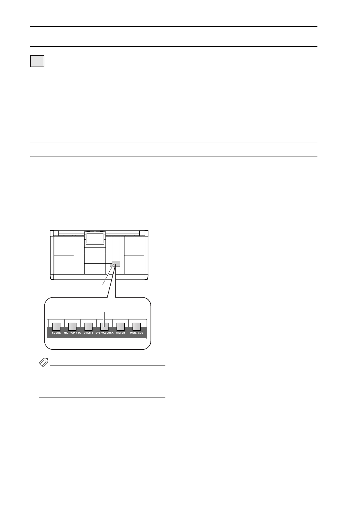
Basic settings (Standard mode)
DSP
x1x1
When starting up the PM1D system for the first time, you will need to select the operation mode of the PM1D (which is
what determines the system configuration and how the components are connected to each other), and set the word clock
that will be shared by the entire system. Once these settings have been made, the PM1D system will automatically
remember them. (However if you modify the configuration of the system, you may need to make settings again.)
Be aware that the display screens and settings differ between Standard mode and Mirror mode. This section explains the
basic settings for Standard mode. If you are using Mirror mode, please proceed to “Basic settings (Mirror mode)”
(
→
p.26).
Selecting the operation mode (Standard mode)
The “operation mode” determines the configuration of the PM1D system and how the components are connected to
each other. The PM1D system version 1.0 supports two modes: “Standard mode” in which one console is used with one
engine, and “Mirror mode” in which one console is used with two engines.
[Procedure]
1. In the LED FUNCTION ACCESS block, press the
[SYS/W.CLOCK] switch several times to access the
screen shown on the following page.
LCD FUNCTION ACCESS
block
[SYS/W.CLOCK] switch
Hint
The switches of the LCD FUNCTION ACCESS block
are used to access specific functions in the display. By
pressing the same switch repeatedly, you can successively access different screens within that function.
22
Page 44

Basic settings (Standard mode)
This is the SYSTEM CONNECTION screen, in
which you can check the connection status of the
various components, and select the operation mode.
2. Click the button located at the right of “OPERA
TION MODE.”
The OPERATION MODE window will appear, in
which you can select the operation mode.
3. Click the button marked “CONSOLE x 1 <->
ENGINE x1.”
Clicking “CONSOLE x 1 <-> ENGINE x1” will select
“Standard mode,” and you will then return to the
previous screen.
If both sets of connectors (1/2)
are connected, two lines will be
displayed in the screen. In this
case, the connector for the
transmitting device in the
graphic will show the number of
the currently-valid connector.
This shows the connection status between the console and
engine. The light blue line in the
screen shows the control signal
connection, and the red line
shows the digital audio signal
connection.
Ve r ify that the OPERATION MODE field indicates
“CONSOLE x1 <-> ENGINE x1.”
-
When you perform this switch, the word clock will
be reset. At this time, noise may be produced from
the output jacks of the CS1D or AO8 (in particular
if an MY8-AT digital I/O card is installed in the
DIO8). In order to protect your speakers, you must
turn down the output of the power amp before
changing this setting.
Hint
In the SYSTEM CONNECTION screen you can also
check the cabling within the system and the status of
each device.
This indicates the type
This indicates the type
of input unit that is con-
of input unit that is connected to each INPUT
nected to each INPUT
connector (1–10) of the
connector (1–10) of the
engine.
engine.
This indicates the type of
input unit that is connected to each OUTPUT
connector (1–6) of the
engine.
If the connection is broken, an
“x” symbol will be displayed
instead of the number.
23
Page 45
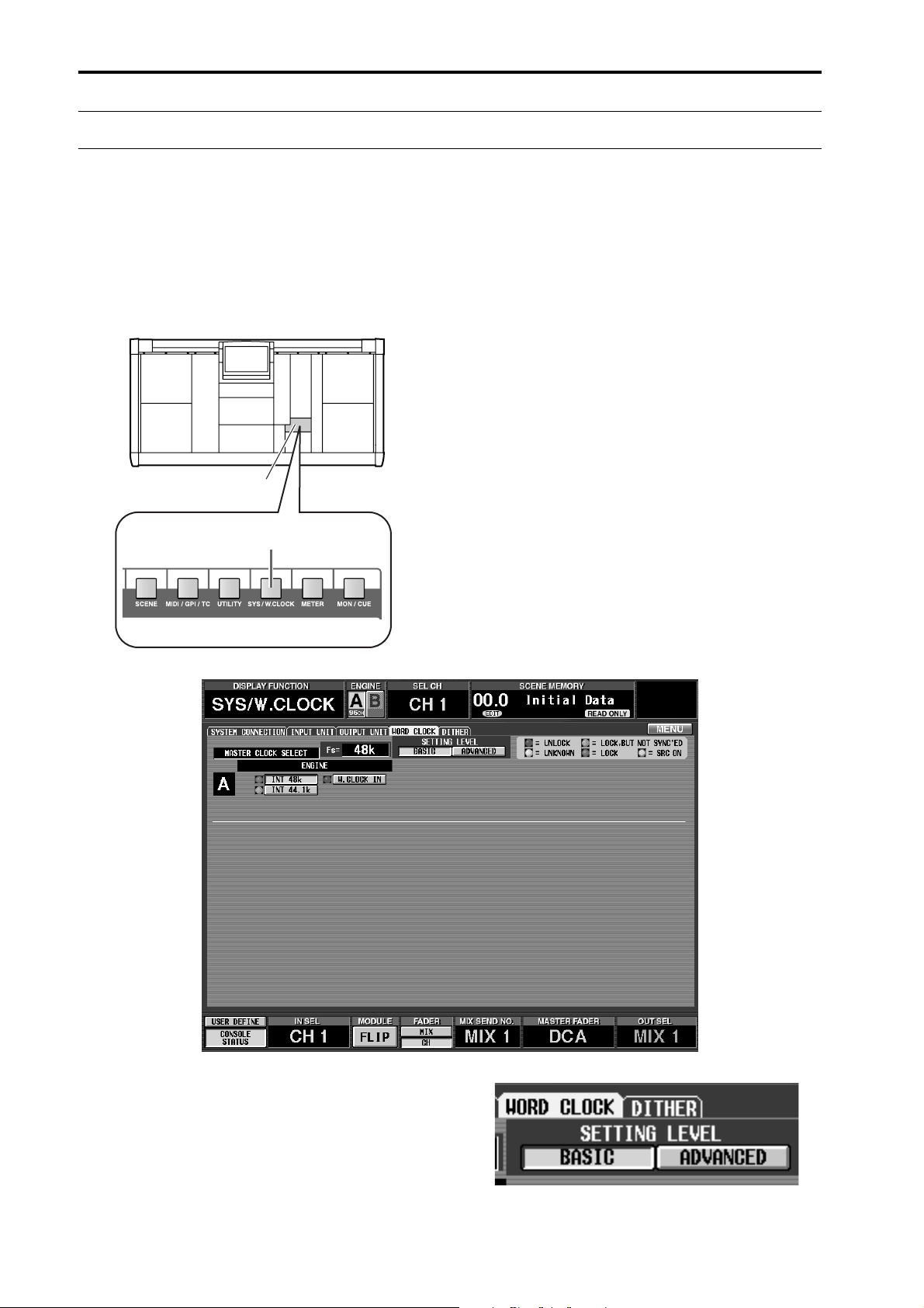
CS1D Operating Manual (Start-up)
Setting the word clock (Standard mode)
In order for the PM1D system to function, word clock (audio system clock) synchronization must be established
between all devices of the system. In this screen you can specify the word clock that will operate the PM1D system. In
general, the frequency of this clock is referred to as the sampling rate or sampling frequency.
[Procedure]
1. In the LCD FUNCTION ACCESS block, press the
[SYS/W.CLOCK] switch several times to access the
following screen.
LCD FUNCTION ACCESS
block
[SYS/W.CLOCK] switch
Settings for the word clock of the PM1D system are
made in this screen.
2. In the screen area marked “SETTING LEVEL,”
make sure that the BASIC button is on (displayed
in green).
If the ADVANCED button is on instead of the BASIC
button, click the BASIC button.
24
Page 46

Hint
When the ADVANCED button is on, you can make
more detailed word clock settings.
3. Click one of the following buttons to select the
word clock source as the word clock master.
In Standard mode you can select one of the following
three choices as the word clock.
When you change the word clock settings, noise
may be heard from the output jacks of the CS1D
and AO8, particularly if an MY8-AT digital I/O
card is installed in the DIO8. To protect your
speaker system, you must turn down the power
amp output before changing the word clock settings. Such a change in the word clock settings can
occur not only when PM1D system internal settings
are changed, but also when the word clock setting is
switched on an external device (e.g., a CD player or
a recording device).
■
ENGINE A
•
INT 48 k (Default setting)
The internal clock of the engine,
48 kHz
•
INT 44.1 k ...........The internal clock of the engine,
44.1 kHz
•
W.CLOCK IN .....Supply a word clock to the
WORD CLOCK IN connector of
the engine
Normally you will select either INT 48 k or INT
44.1 k. If you are using an external clock generator as
the master, select W.CLOCK IN, and supply a word
clock to the WORD CLOCK IN jack of the engine/
console.
If when you change the word clock settings, the AI8
or AO8 indicator shows “UL” or the display shows a
message warning that the word clock is not synchronized, check the connections between the
engine and console, and the connections between
the engine and the input/output units.
Basic settings (Standard mode)
25
Page 47

Basic settings (Mirror mode)
DSP
x2x2
This section explains how to select the operation mode and word clock master when using the PM1D system in Mirror
mode.
Selecting the operation mode (Mirror mode)
[Procedure]
1. In the LCD FUNCTION ACCESS block, press the
[SYS/W.CLOCK] switch several times to access the
following screen.
LCD FUNCTION ACCESS
block
[SYS/W.CLOCK] switch
This is the SYSTEM CONNECTION screen, in
which you can check the connection status of each
device, and select the operation mode.
26
Page 48

Basic settings (Mirror mode)
2. Click the button located at the right of “OPERA
TION MODE.”
The OPERATION MODE window will appear, in
which you can select the operation mode.
3. Click the button marked “CONSOLE x 1 <->
ENGINE x2 (Mirror Mode).”
Clicking “CONSOLE x 1 <->ENGINE x2 (Mirror
Mode)” will select “Mirror mode,” and you will then
return to the previous screen. Verify that the OPER-
If both jacks (1/2) of the same type
are connected, two lines will be disThis shows the connection status
between the console and engine.
The light blue lines in the screen
show control signal connections,
and the red lines show digital audio
signal connections.
played in the screen. You can click a
button in the jack area to select the
jack number (1 or 2) that is currently
enabled. If the connection is broken,
an "x" symbol will be displayed
instead of the number.
-
ATION MODE field indicates “CONSOLE x1 <->
ENGINE x2 (Mirror Mode).”
When you perform this switch, the word clock will be
reset. At this time, noise may be produced from the
output jacks of the CS1D or AO8 (in particular if an
MY8-AT digital I/O card is installed in the DIO8). In
order to protect your speakers, you must turn down the
output of the power amp before changing this setting.
Hint
In the SYSTEM CONNECTION screen you can also
check the cabling within the system and the status of
each device.
This indicates the type
of input unit that is connected to each INPUT
connector (1–10) of the
engine.
This indicates the type
of input unit that is
connected to each
OUTPUT connector
(1–6) of the engine.
This shows the connection status
between the console and engine.
The light blue lines in the screen
show control signal connections,
and the red lines show digital audio
signal connections.
If both jacks (1/2) of the same type
are connected, two lines will be displayed in the screen. You can click a
button in the jack area to select the
jack number (1 or 2) that is currently
enabled. If the connection is broken,
an "x" symbol will be displayed
instead of the number.
When using the PM1D system in Mirror mode, use this screen to verify that the same configuration of components
is connected to the INPUT connectors and OUTPUT connectors of engines A and B. Be aware that if the two configurations are different, the signal flow will change when you switch between engine A and engine B, and the
desired state will not be obtained.
This indicates the type
of input unit that is connected to each INPUT
connector (1–10) of the
engine.
This indicates the type
of input unit that is
connected to each
OUTPUT connector
(1–6) of the engine.
27
Page 49

CS1D Operating Manual (Start-up)
Setting the word clock (Mirror mode)
This section explains how to check whether the word clock settings are appropriate when using the PM1D system in mirror mode.
[Procedure]
1. In the LCD FUNCTION ACCESS block, press the
[SYS/W.CLOCK] switch several times to access the
following screen.
LCD FUNCTION ACCESS
block
[SYS/W.CLOCK] switch
Settings for the word clock of the PM1D system are
made in this screen.
2. In the “SETTING LEVEL” section of the screen,
make sure that the ADVANCED button is on (displayed in green).
The ADVANCED button will automatically be on if
you select “CONSOLE x1 <-> ENGINE x2 (Mirror
Mode)” in the SYSTEM CONNECTION screen
(
→
p.26).
28
•
ADVANCED button on
Page 50

Basic settings (Mirror mode)
3. Make sure that the master word clock and the word
clock input select are set as follows.
MASTER CLOCK SELECT
•
The W.CLOCK of the engine or console is on
WORD CLOCK INPUT SELECT
Console W.CLOCK IN
Engine A/B W.CLOCK IN
Each unit W.CLOCK IN
Wo rd clock settings will automatically be as shown
above.
Although it is possible to change this setting manu
ally, you should supply a word clock from an external clock generator to each device (
→
refer to the
connection methods on p.10, 12), and use the system with the above settings to ensure that the system operates in a stable manner.
With these settings, the word clock from the external clock generator will be supplied directly to each
device in the PM1D system even if you switch
between engines A and B in case of problems, so
that the clock itself will not be switched, and the
change will occur in the shortest possible time.
If when you change the word clock settings, the AI8
or AO8 indicator shows “UL” or the display shows a
message warning that the word clock is not synchronized, check the connections between the
engines and console, and the connections between
the engines and the input/output units.
-
29
Page 51

Checking the operation of input units
This section explains how to check the operation of an input unit connected to the DSP1D-EX {DSP1D} engine.
The general procedure is as follows.
Connect an input source to the input unit
mm
mm
Connect a monitor system (or headphones) to the MONITOR OUT A jacks of the console (or to the MONITOR A
headphone jack)
mm
mm
Tu rn on the power in the order of input unit
mm
mm
Patch the input unit to an input channel
mm
mm
Press the [CUE] switch of the input channel
mm
mm
Check whether the signal is output from the MONITOR OUT A jacks (or the MONITOR A headphone jack)
→
DSP1D-EX {DSP1D} engine
→
CS1D console
→
monitor system
Preparations for checking
Before you begin checking the operation of the input unit, make sure that you have performed the following actions.
•
Connect the various components that are part of
the PM1D system (
•
Use the indicators/LEDs of the input/output units
and the engine to verify that the components are
correctly connected to each other (
•
Set the operation mode and the word clock master
as appropriate for the configuration of the PM1D
system that you are using (
→
p.6–13)
→
p.22–29).
→
p.14–21)
30
Page 52

Checking the operation of input units
Connect the monitor system
In order to check the operation of an input unit, you must connect a monitor system such as powered monitor speakers
or a power amp + speaker to the MONITOR OUT A jacks located on the rear panel of the CS1D console. (Since the purpose of this is to check the operation, high power monitors are not necessary.)
If you will be monitoring through headphones, connect them to the PHONES MONITOR A jack located on the front
panel of the CS1D console.
Monitor
system
LR
MONITOR OUT A jacks
CONSOLE (CS1D)
Headphones
Please do not use the MONITOR A/B headphone
jacks located on the top panel of the console (in the
SELECTED INPUT CHANNEL block) simultaneously with the PHONES MONITOR A/B jacks
located on the front panel. Doing so can cause the
CS1D to malfunction due to excessive current.
MONITOR A
headphone jacks
31
Page 53

Connect an input source
Connect one of the following input sources according to the type of input unit or card that you wish to check.
•
To check a mic/line input card (LMY2-ML)
installed in the AI8
Connect a line output device such as a CD player or
DAT recorder to input jacks 1A and 2A of the LMY2ML.
12345678
AI8 input unit
INPUT UNIT NO.
PHANTOM MASTER
ON
OFF
POWER
ON/ OFF
ANALOG INPUT BOX
+48V
•
To check an input channel of a digital I/O card
(MY8-AT, MY8-TD, MY8-AE) installed in the DIO8
Connect the digital output connector of a DAT
recorder or digital MTR (multi-track recorder) that
matches the format of your digital I/O card. In this
case, make connections and settings so that the signals are sent from the recorder to input channels 1/2
of the digital I/O card.
DIO8 digital input/output unit
PORT B SELECTOR
I/O UNIT ID
5-8
1-4
POWER
ON/ OFF
SIGNAL
ANALOG IN
CH2A CH1B CH1A
CH2B
MIC/Line-Platine (LMY2-ML)
B
SIGNAL
MIC/LINE INPUT CARD
MODEL LMY2-ML
B
LR
CD player/DAT recorder
•
To check an AD card (LMY4-AD) installed in the
AI8
Connect a line output device such as a CD player or
DAT recorder to input jacks 1/2 of the LMY4-AD.
12345678
AI8 input unit
INPUT UNIT NO.
PHANTOM MASTER
ON
OFF
POWER
ON/ OFF
ANALOG INPUT BOX
+48V
OUT
IN
DIGITAL I/O CARD
MODEL MY8-AT
Digital-E/A-Platine (MY8-AT)
DIGITAL OUT
ADAT
ADAT digital MTR
TASCAM digital MTR
Interface (TDIF-1)
Tascam Digital Audio
DIGITAL I/O CARD
MODEL MY8-TD
Digital-E/A-Platine (MY8-TD)
WORD CLOCK OUT
Digital-E/A-Platine (MY8-AE)
Special AES/
EBU cable for
the MY8-AE
DIGITAL I/O
8-TRACK DIGITAL
AES/EBU
DIGITAL I/O CARD
MODEL MY8-AE
SIGNAL
ANALOG IN
CH3 CH2 CH1
CH4
SIGNAL
SIGNAL
AD CARD
MODEL LMY4-AD
SIGNAL
LR
CD player/DAT recorder
32
INPUT 1/2 3/4 5/6 7/8
OUT
PUT 1/2 3/4 5/6 7/8
(female) (male)
DIGITAL OUT (AES/EBU)
00.00.00.00
DAT
DAT recorder
Page 54

Checking the operation of input units
Patch the input unit to an input channel
Simply connecting a source to an input unit does not cause that signal to be input to the PM1D system. In order to send
signals to the PM1D system, you must assign (patch) the input jacks of the input unit to input channels of the PM1D system. This operation is performed within the display of the CS1D console.
[Procedure]
1. Turn on the power in the order of PM1D system
monitor system.
2. In the LCD FUNCTION ACCESS block, press the
INPUT [PATCH] switch several times to access the
following screen.
LCD FUNCTION ACCESS
block
INPUT [PATCH] switch
→
This is the INPUT PATCH screen, where signals
from an input unit or effect return can be patched to
input channels.
33
Page 55

CS1D Operating Manual (Start-up)
Number of
the patch
destination
input channel.
In this grid, input jacks (horizontal rows) can be patched to input channels (vertical columns). A
symbol is displayed to indicate a currently-patched grid location.
Patch source
input jack.
From the top
row, the display shows
the type and
ID of the input
unit, the number of the slot
in which the
input card is
installed, and
the number of
the channel
(jack) within
the card.
●
Hint
The switches in the LCD FUNCTION ACCESS block
are used to access the desired function in the display.
Each function is divided into multiple screens, and
you can press the same switch repeatedly to cycle
through the displayed screens.
3. Move the left/right scroll bar so that the visible area
of the horizontal rows (patch source) shows the
input unit to which the input source is connected.
Use the left/right scroll bar to access input units that
are not currently shown in the visible area.
Click the / buttons to
switch the display in steps of a
unit.
Click the / buttons to
switch the display in steps of a
slot.
Drag this box to move the
displayed area to left or
right.
You can also click this area to
move the displayed portion.
Click the / buttons
to switch the display in steps
of a unit.
Click the / buttons
to switch the display in steps
of a slot.
4. Patch the input source to input channels 1/2.
In the IN PATCH screen, the jack to which the input
source is connected can be patched to the desired
input channel by making a
●
symbol appear in the
grid where the patch source intersects the patch destination. There are two ways to do this, as follows.
34
Page 56

Checking the operation of input units
Using the switches of the console
1. Use the [CURSOR] switches in the data entry block
to move the cursor (the red frame) in the display to
the desired grid.
Data entry block
[CURSOR] switch
Using the track pad of the console
1. Use the track pad to move the cursor to the desired
grid. (The cursor will change to the shape of a finger.)
Data entry block
Track pad
[ENTER] switch
2. Press the [ENTER] switch to make a
appear.
●
symbol
2. Click the desired grid to make the
●
symbol
appear.
The screen will appear as follows when an input
source has been patched to input channels 1/2.
•
For an AI8 with a mic/line input card (LMY2-ML)
installed
•
For an AI8 with an AD card (LMY4-AD) installed
•
For a DIO8 with a digital I/O card installed
35
Page 57

CS1D Operating Manual (Start-up)
PAN
TO ST
CLIP
R
+48V
INPUT
INS A
B
L
GAIN
SEL
-68
+
THR
-
COMP
+
THR
-
CLIP
6
12
18
30
60
GATE
+10
PAN
TO ST
CLIP
R
+48V
INPUT
INS A
B
L
GAIN
SEL
-68
+
THR
-
COMP
+
THR
-
GATE
+10
CLIP
6
12
18
30
60
ONON
CUE
60
CUE
60
Monitor the input signal
After you have patched an input source to an input channel, press the [CUE] switch for that input channel and check
whether it is output from the MONITOR OUT jacks.
[Procedure]
1. Play back the input source, and check that the
meter LEDs light for input channels 1/49 and 2/50
in INPUT block 1 of the console.
INPUT block 1
[GAIN] encoder
In the CUE section of the MASTER block, make
sure that the [SOLO] switch, the [INPUT AFL]
switch, and the [LAST CUE] switch are off (LED
dark). If any of these switches are on, it may not be
possible to monitor the signal from the MONITOR
OUT A jacks or the MONITOR A headphone jack
even though the [CUE] switch of the input channel
is pressed.
Monitoring will also be impossible if the CUE
INTERRUPTION button has been turned off in the
MON/CUE function MONITOR A screen. Please
check whether this button has been turned off.
(“CS1D Reference Manual (Software)” →p.71.)
MASTER block
[INPUT AFL]
switch
[SOLO]
switch
Meter LEDs for
input channels 1/49
and 2/50
[LAST CUE] switch
[CUE] switch
3. In the MONITOR A section of the MASTER block,
turn on the MONITOR A [ON] switch and raise the
MONITOR A [LEVEL] volume to an appropriate
level. Also raise the volume of your monitor system.
MONITOR A
If the input source is connected to a mic/line input
card (LMY2-ML), adjust the [GAIN] encoder so
that the CLIP segment of the meter LED does not
light.
2. Press the [CUE] switches of input channels 1/49
and 2/50 to make the switch LEDs light.
The input signals of input channels 1/2 will be sent to
the monitoring bus (CUE bus).
36
[LEVEL] volume
MONITOR A
[ON] switch
MONITOR A
PHONES [LEVEL]
volume
Page 58

Checking the operation of input units
Hint
When monitoring through the MONITOR A headphone jack, raise the MONITOR A PHONES
[LEVEL] volume (located in the MONITOR A section of the MASTER block) to an appropriate level.
If you are now able to monitor the signal, you have
verified that the input unit/card to which the source
is connected is operating normally.
4. As necessary, perform the same operational check
for other input units or cards.
If you are unable to monitor an input source, check
the following points.
Meter LEDs of the INPUT block do not light
• Is the input source connected appropriately?
→Check the unit/card to which the input source is
connected (→p.32)
• When using a mic/line input card (LMY2-ML), is
the input source connected to input jacks 1A and
2A?
→When the PM1D system is in the default state,
input jacks 1B or 2B cannot be used without
changing the settings. Re-connect to input jacks 1A
and 2A (→p.32).
• Has the input unit/card to which the input source
is connected been correctly patched to the input
channel?
→Check the settings of the IN PATCH screen
(→p.33).
Meter LEDs of the INPUT block do light, but the signal
is not output from MONITOR OUT jacks A or the
MONITOR A headphone jack
• Is your monitor system connected appropriately?
→Check the connections of the monitor system/
headphones.
• Is the monitor volume raised?
→Raise the MONITOR A [LEVEL] or [PHONES]
volume to an appropriate level.
• In the MASTER block CUE section, have the
[SOLO], [INPUT AFL], or [LAST CUE] switches
been turned off?
→If any of these switches are on, it may not be possi-
ble for the signal of the input channel whose
[CUE] switch was pressed to be monitored from
MONITOR OUT jacks A or the MONITOR A
headphone jack. You must turn off all of these
switches. (“CS1D Reference Manual (Hardware)”
→p.81)
The meter LEDs of the INPUT block are lit, and a
signal is output from the MONITOR A headphone
jack, but no signal is output from MONITOR OUT
jacks A
• Is the CUE INTERRUPTION button (MON/CUE
function MONITOR A screen) turned on?
→Monitoring is not possible if the CUE INTERRUP-
TION button is turned off. Turn this button on.
(“CS1D Reference Manual (Software)” →p.71)
• In the SELECTED INPUT CHANNEL block, has
the MODULE [FLIP] switch been turned on (LED
lit)?
→When the MODULE [FLIP] switch is on, the mod-
ules of INPUT blocks 1 and 2 will be exchanged.
Press the MODULE [FLIP] switch to make the
LED go dark. (“CS1D Reference Manual (Hard-
ware)” →p.5)
• In the MASTER block GLOBAL LAYER section,
has the [49-96] switch been turned on (LED lit)?
→On the 96 channel model when the GLOBAL
LAYER [49-96] switch is on (LED lit), channels
49–96 will be selected as the input channels that
are controlled from the top panel of the CS1D.
{This switch has no function on the 48 channel
model.} To control channels 1–48, press the GLOBAL LAYER [1-48] switch. (“CS1D Reference
Manual (Hardware)” →p.5)
37
Page 59

Checking the operation of an output unit
This section explains the procedure for checking the operation of an output unit connected to the DSP1D-EX {DSP1D}
engine. The general procedure is as follows.
Connect an input source to an input unit
mm
mm
Connect your monitor system to an output unit
mm
mm
Tu rn on the power in the order of input unit → DSP1D-EX {DSP1D} engine → CS1D console → monitor system
mm
mm
Patch the input unit to an input channel
mm
mm
Patch the output unit to the STEREO A channel
mm
mm
Send the input channel signal to the STEREO bus
mm
mm
Check whether the signal is output from the STEREO OUT A jacks
Preparations for checking
Before you begin checking the operation of an output unit, make sure that the following actions have been completed.
• Connect the various components that are part of
the PM1D system (→p.6–13)
• Use the indicators/LEDs of the input/output units
and the engine to verify that the components are
correctly connected to each other (→p.14–21)
• Set the operation mode and the word clock master
as appropriate for the configuration of the PM1D
system that you are using (→p.22–29).
38
Page 60

Checking the operation of an output unit
Connect the monitor system
In order to check the operation of an analog output unit, you will need to connect a monitor system such as a set of powered speakers or a power amp + speakers to a DA card (LMY4-DA) installed in the AO8 analog output unit.
1234567
AO8 analog output unit
ANALOG OUT
DA CARD
CH4 CH3 CH2 CH1
MODEL LMY4-DA
DA-Platine (LMY4-DA)
SIGNAL SIGNAL SIGNAL SIGNAL
LR
8
OUTPUT UNIT NO.
INPUT SELECTOR
A
B
POWER
ON/ OFF
ANALOG OUTPUT BOX
Monitor system
If you are checking the output channels of a DIO8
digital input/output unit, connect the output connector of the digital I/O card (MY8-AT, MY8-TD,
MY8-AE) to the digital input connector of a DAT
recorder or digital MTR (multi-track recorder) of
the same format as that card. In this case, it will not
be possible to directly monitor the signal via the
monitor system, so you will need to arrange things
so that the signal can be monitored via the headphone jack or analog output jacks of the recorder.
39
Page 61

CS1D Operating Manual (Start-up)
Connect an input source
As a sound source for checking, connect a line output device such as a CD player or DAT recorder to an input unit.
12345678
AI8 analog input unit
SIGNAL
ANALOG IN
SIGNAL
CH3 CH2 CH1
SIGNAL
AD CARD
CH4
MODEL LMY4-AD
SIGNAL
INPUT UNIT NO.
PHANTOM MASTER
ON
OFF
POWER
ON/ OFF
ANALOG INPUT BOX
+48V
LR
CD player/DAT recorder
40
Page 62

Checking the operation of an output unit
Patch the input unit to an input channel
Patch the input jack to which you connected the input source to input channels 1/2. For details of the procedure, refer to
page 33.
[Procedure]
1. Turn on the power in the order of the PM1D system
→ monitor system.
2. In the LCD FUNCTION ACCESS block, press the
INPUT [PATCH] switch several times to access the
following screen.
LCD FUNCTION ACCESS
block
INPUT [PATCH] switch
3. Patch the input source to input channels 1/49 and
2/50.
The following illustration shows an example of when
jacks 1/2 of an AD card (LMY4-AD) installed in slot
1 of the AI8 are patched to input channels 1/2.
41
Page 63

CS1D Operating Manual (Start-up)
Patch the STEREO A channel to an output unit
Similarly to the case for an input unit, outputting a signal from the PM1D system requires more than simply connecting
your monitor system to an output unit. In order to output a signal, you must also assign (patch) an output channel (MIX
channel, MATRIX channel, STEREO A/B channel) of the PM1D system to the jacks of an output unit. This action is performed within the display of the CS1D console.
Here’s how to patch the STEREO A channel output signal to the output unit to which your monitor system is connected.
[Procedure]
1. In the LCD FUNCTION ACCESS block, press the
OUTPUT [PATCH] switch several times to access
the following screen.
LCD FUNCTION ACCESS
block
OUTPUT [PATCH] switch
42
Page 64
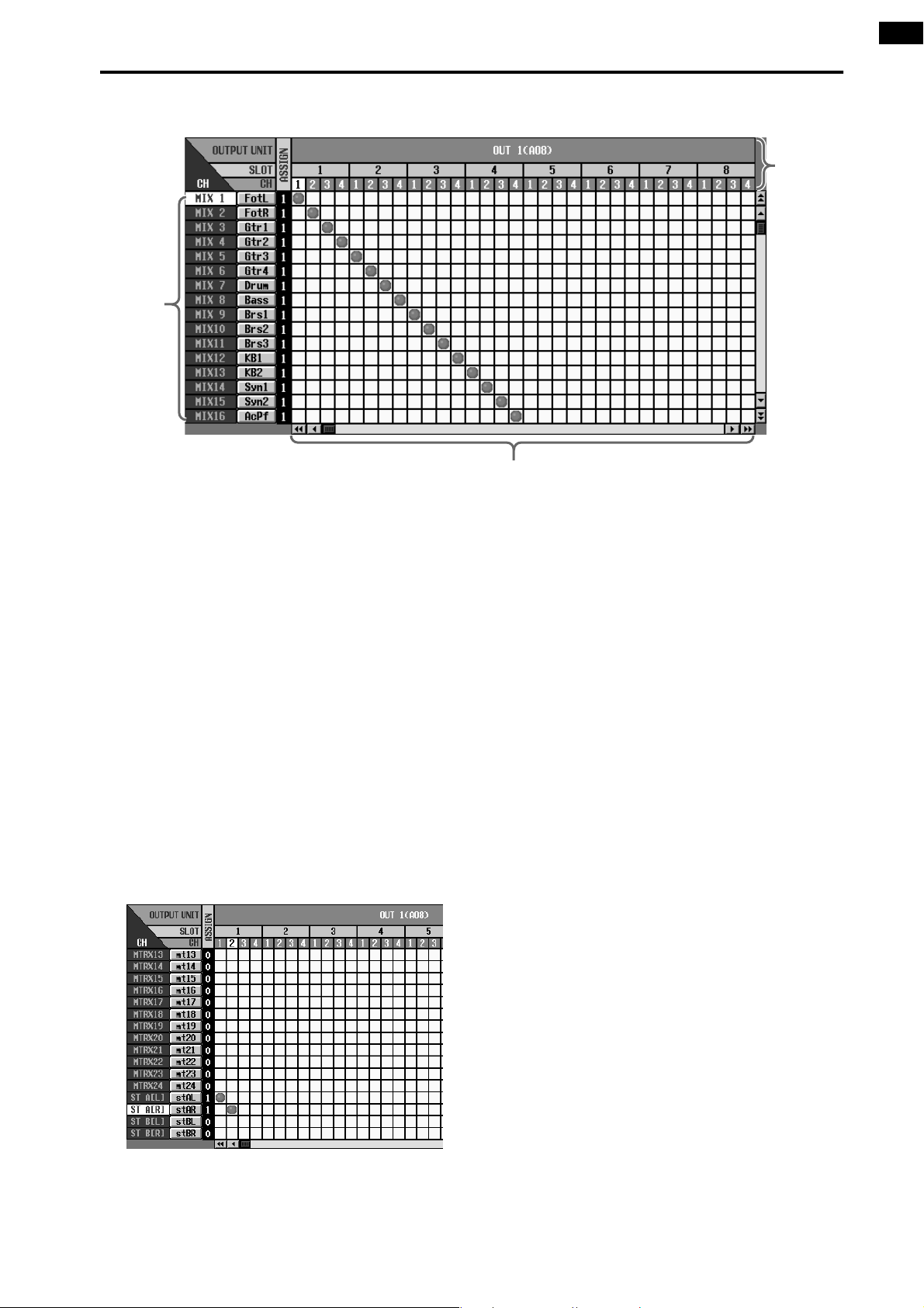
Patch source
output
channels.
Checking the operation of an output unit
Patch destination output jacks.
From the
top, this
area shows
the type and
ID of the
output unit,
the number
of the slot in
which the
output card
is installed,
and the
channel
(jack) number within
the card.
In this grid, output jacks (horizontal rows) can be patched to output channels (vertical columns).
A ● symbol will be displayed for currently-patched grids. This is the OUTPUT PATCH screen in
which the output signals of the output channels can be patched to output units or to the inputs of
the internal effects.
2. Use the up/down scroll bars to make “ST A[L]” and
“ST A[R]” appear in the vertical column (patch
source) area.
Use the up/down scroll bar to see output channels
that are not currently visible. “ST A[L]” and “ST
A[R]” correspond to STEREO A channels L and R
respectively.
3. Use the left/right scroll bar to make the output unit
to which your monitor system is connected appear
in the horizontal row (patch destination) of the display.
4. Patch “ST A[L]” and “ST A[R]” to the jacks to which
your monitor system is connected.
The following illustration shows the example of
when jacks 1/2 of a DA card (LMY4-DA) installed in
slot 1 of the AO8 are patched to the L/R channels of
STEREO A.
43
Page 65

CS1D Operating Manual (Start-up)
PAN
TO ST
CLIP
R
+48V
INPUT
INS A
B
L
GAIN
SEL
-68
+
THR
-
COMP
+
THR
-
CLIP
6
12
18
30
60
GATE
+10
PAN
TO ST
CLIP
R
+48V
INPUT
INS A
B
L
GAIN
SEL
-68
+
THR
-
COMP
+
THR
-
GATE
+10
CLIP
6
12
18
30
60
ONON
CUE
60
CUE
60
M
T
Send the input signals of input channels 1/2 to the STEREO bus
With the operations you have performed up to this point, the signals of the STEREO bus of the PM1D system will be
output to the output jacks to which your monitor system is connected. Now we will send the signals of the input source
to the STEREO bus to verify that they can be monitored via your monitor system.
[Procedure]
1. Play back the input source. In INPUT block 1 of the
console, verify that the meter LEDs light for input
channels 1/49 and 2/50.
INPUT block 1
[TO ST] switch
[GAIN] encoder
[ON] switch
2. If the input source is connected to a mic/line input
card (LMY2-ML), adjust the [GAIN] encoder so
that the CLIP segment of the meter LED does not
light.
3. Turn on the [ON] switches of input channels 1/49
and 2/50 (so that the LEDs are lit).
4. Turn on the [TO ST] switches of input channels 1/
49 and 2/50.
5. Raise the faders of input channels 1/49 and 2/50 to
the 0 position (nominal level).
6. In the STEREO OUTPUT block, turn on the STEREO [ON] switch of the ST OUTPUT A channel.
STEREO OUTPUT block
STEREO [ON]
switch of the ST
OUTPUT A
channel
Meter LEDs for
input channels 1/49
and 2/50
[CUE] switch
Fader
ON
TO MTRX
SEL
INS
10
5
0
5
10
20
RCL
MUTE
30
SAFE
40
50
60
CUE
ST OUTPUTAS
44
Page 66
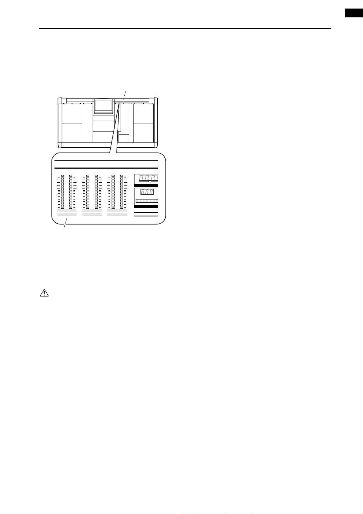
Checking the operation of an output unit
U
M
N
7. In the STEREO OUTPUT block, raise the ST OUTPUT A channel fader.
At this time, the STEREO A L/R meters in the meter
bridge block will show the output level of the STEREO A channel.
Meter bridge block
CLIP
-4
-8
-12
-16
-20
-24
-30
-40
-50
-70
LR
STEREO A
CLIP
-4
-8
-12
-16
-20
-24
-30
-40
-50
-70
LR
STEREO B
CLIP
-4
-8
-12
-16
-20
-24
-30
-40
-50
-70
LR
CUE
HOUR
NUMBER
SCE
MIN
TI
STEREO A L/R meters
If the signal can now be heard from your monitor
system, you have verified that the output unit/card to
which the source is connected is functioning correctly.
8. As necessary, use the same procedure to check the
operation of other output units or cards.
If the input source could not be monitored, check
the following points.
Meter LEDs in the INPUT block do not light
• Is the input source connected appropriately?
→Check the unit/card to which the input source is
connected (→p.32).
• When using a mic/line input card (LMY2-ML), is
the input source connected to input jacks 1A and
2A?
→When the PM1D system is in the default state,
input jacks 1B or 2B cannot be used without
changing the settings. Re-connect to input jacks 1A
and 2A (→p.32).
• Has the output unit/card to which the input source
is connected been correctly patched to the input
channel?
→Check the settings of the IN PATCH screen
(→p.33).
• In the SELECTED INPUT CHANNEL block, has
the MODULE [FLIP] switch been turned on (LED
lit)?
→When the MODULE [FLIP] switch is on, the mod-
ules of INPUT blocks 1 and 2 will be exchanged.
Press the MODULE [FLIP] switch to make the
LED go dark. (“CS1D Reference Manual (Hard-
ware)”→p.5)
• In the MASTER block GLOBAL LAYER section,
has the [49-96] switch been turned on (LED lit)?
→On the 96 channel model when the GLOBAL
LAYER [49-96] switch is on (LED lit), channels
49–96 will be selected as the input channels that
are controlled from the top panel of the CS1D.
{This switch has no function on the 48 channel
model.} To control channels 1–48, press the GLOBAL LAYER [1-48] switch. (“CS1D Reference
Manual (Hardware)” →p.5)
STEREO A L/R meters in the meter bridge block do not
light
• Is the input channel [ON] switch turned off?
→In the INPUT block, turn on the [ON] switch for
input channels 1/49 and 2/50 (→p.44).
• Is the [TO ST] switch of the input channel turned
off?
→In the INPUT block, turn on the [TO ST] switch
for channels 1/49 and 2/50 (→p.44).
• Is the input channel fader lowered?
→In the INPUT block, raise the faders for input
channels 1/49 and 2/50 (→p.44).
STEREO A L/R meters in the meter bridge block are lit,
but there is no output from the output unit
• Is the STEREO A channel STEREO [ON] switch
turned off?
→In the STEREO OUTPUT block, turn on the STE-
REO [ON] switch of the STEREO A channel
(→p.44).
• Is the STEREO fader of the STEREO A channel
lowered?
→In the STEREO OUTPUT block, raise the STEREO
fader of the STEREO A channel (→p.45).
• Is the monitor system connected appropriately?
→Check the connections of the monitor system
(→p.39).
• Are the output channels patched appropriately?
→In the OUT PATCH screen, check whether the
STEREO A L/R channels are appropriately patched
to the output unit/card to which your monitor sys-
tem is connected (→p.42).
45
Page 67

CS1D Operating Manual (Start-up)
• Is the Solo function turned on?
→If the [SOLO] switch is turned on in the MASTER
block CUE section, and the [CUE] button of any
channel is turned on, the signals of the other channels will be muted. Turn off the [SOLO] switch
(“CS1D Reference Manual (Hardware)” →p.81).
Turn off the power
You have now finished the system check of the “CS1D Operating Manual (Start-up).”
We recommend that you store the current state as a scene memory before you turn off the power supply (PW1D). If the
current unit connection state differs from the unit connection state the next time the power is turned on, patch settings
etc. may be modified. For the procedure of storing a scene, refer to “CS1D Reference Manual (Hardware)” (→p.89) or
“CS1D Reference Manual (Software)” (→p.18).
Lower the faders of the STEREO OUTPUT block, and turn off the power in the order of the monitor system → PM1D
system.
Before you move the CS1D, you must tilt the display backward until it locks into place.
Before turning on the engine (DSP1D) or the console power supply (PW1D), you must wait at least five seconds
after the power was turned off. Failing to observe this waiting period may cause malfunctions.
46
Page 68

Operating Manual
(Basic Operation)
Page 69

Contents
Chapter 1. Introduction . . . . . . . . . . . . . . . . . . . . . . . . . . . . . . . .1
About the “CS1D Operation Manual (Basic Operation)” . . . . . . . . . . . . . . . . . . . . 1
Printing conventions in the “CS1D Operation Manual (Basic Operation)” . . . . . . . . . 1
Overview of the PM1D system . . . . . . . . . . . . . . . . . . . . . . . . . . . . . . . . . . . . . . . . . 2
Full-digital/separate type SR mixing system . . . . . . . . . . . . . . . . . . . . . . . . . . . . 2
Component structure . . . . . . . . . . . . . . . . . . . . . . . . . . . . . . . . . . . . . . . . . . . . 2
Signal flow in the PM1D system . . . . . . . . . . . . . . . . . . . . . . . . . . . . . . . . . . . . 4
Number of inputs/outputs and channel structure . . . . . . . . . . . . . . . . . . . . . . . 6
MIX buses/MATRIX buses . . . . . . . . . . . . . . . . . . . . . . . . . . . . . . . . . . . . . . . . . 8
Scene memories/Libraries . . . . . . . . . . . . . . . . . . . . . . . . . . . . . . . . . . . . . . . . . 8
Word clock synchronization. . . . . . . . . . . . . . . . . . . . . . . . . . . . . . . . . . . . . . . . 8
Chapter 2. The user interfaces of the CS1D . . . . . . . . . . . . . . . .9
About the user interfaces . . . . . . . . . . . . . . . . . . . . . . . . . . . . . . . . . . . . . . . . . . . . . 9
User interfaces within the display. . . . . . . . . . . . . . . . . . . . . . . . . . . . . . . . . . . . 9
User interface on the top panel of the CS1D . . . . . . . . . . . . . . . . . . . . . . . . . . 11
External user interfaces . . . . . . . . . . . . . . . . . . . . . . . . . . . . . . . . . . . . . . . . . . 12
Various basic operations. . . . . . . . . . . . . . . . . . . . . . . . . . . . . . . . . . . . . . . . . . . . . 14
Click . . . . . . . . . . . . . . . . . . . . . . . . . . . . . . . . . . . . . . . . . . . . . . . . . . . . . . . . 14
Drag . . . . . . . . . . . . . . . . . . . . . . . . . . . . . . . . . . . . . . . . . . . . . . . . . . . . . . . . 14
Drag and drop. . . . . . . . . . . . . . . . . . . . . . . . . . . . . . . . . . . . . . . . . . . . . . . . . 15
Scroll . . . . . . . . . . . . . . . . . . . . . . . . . . . . . . . . . . . . . . . . . . . . . . . . . . . . . . . . 15
Accessing the desired screen . . . . . . . . . . . . . . . . . . . . . . . . . . . . . . . . . . . . . . 16
Button operations . . . . . . . . . . . . . . . . . . . . . . . . . . . . . . . . . . . . . . . . . . . . . . 17
Moving the cursor . . . . . . . . . . . . . . . . . . . . . . . . . . . . . . . . . . . . . . . . . . . . . . 18
Adjusting the value of a knob or fader . . . . . . . . . . . . . . . . . . . . . . . . . . . . . . . 19
Assigning a name . . . . . . . . . . . . . . . . . . . . . . . . . . . . . . . . . . . . . . . . . . . . . . 20
Chapter 3. Audio connections and patching. . . . . . . . . . . . . . .22
Audio connections . . . . . . . . . . . . . . . . . . . . . . . . . . . . . . . . . . . . . . . . . . . . . . . . . 22
Audio connections for an analog input unit . . . . . . . . . . . . . . . . . . . . . . . . . . . 22
Audio connections for an analog output unit. . . . . . . . . . . . . . . . . . . . . . . . . . 24
Audio connections for a digital input/output unit . . . . . . . . . . . . . . . . . . . . . . 25
Audio connections for the console. . . . . . . . . . . . . . . . . . . . . . . . . . . . . . . . . . 26
Patching . . . . . . . . . . . . . . . . . . . . . . . . . . . . . . . . . . . . . . . . . . . . . . . . . . . . . . . . . 28
Input channel patching . . . . . . . . . . . . . . . . . . . . . . . . . . . . . . . . . . . . . . . . . . 28
Output channel patching . . . . . . . . . . . . . . . . . . . . . . . . . . . . . . . . . . . . . . . . 30
Chapter 4. Basic operation for input channels . . . . . . . . . . . . .32
About input channels . . . . . . . . . . . . . . . . . . . . . . . . . . . . . . . . . . . . . . . . . . . . . . . 32
Blocks used to control input channels . . . . . . . . . . . . . . . . . . . . . . . . . . . . . . . 32
Changing the channel assignments . . . . . . . . . . . . . . . . . . . . . . . . . . . . . . . . . 33
ii
Page 70

Contents
Basic operation INPUT blocks/ST IN block . . . . . . . . . . . . . . . . . . . . . . . . . . . . . . 34
INPUT block/ST IN block controls and functions . . . . . . . . . . . . . . . . . . . . . . . 34
Head amp settings . . . . . . . . . . . . . . . . . . . . . . . . . . . . . . . . . . . . . . . . . . . . . 36
Sending a signal from an input channel to a STEREO bus . . . . . . . . . . . . . . . . 38
Sending a signal from an input channel to a MIX bus . . . . . . . . . . . . . . . . . . . 39
Pairing settings . . . . . . . . . . . . . . . . . . . . . . . . . . . . . . . . . . . . . . . . . . . . . . . . 43
Basic operation in the SELECTED INPUT CHANNEL block . . . . . . . . . . . . . . . . . . 44
Controls and functions of the SELECTED INPUT CHANNEL block . . . . . . . . . . 44
Head amp settings . . . . . . . . . . . . . . . . . . . . . . . . . . . . . . . . . . . . . . . . . . . . . 46
Sending signals from an input channel to the STEREO bus . . . . . . . . . . . . . . . 47
Sending signals from an input channel to a MIX bus. . . . . . . . . . . . . . . . . . . . 49
Using the delay . . . . . . . . . . . . . . . . . . . . . . . . . . . . . . . . . . . . . . . . . . . . . . . . 51
Using the compressor . . . . . . . . . . . . . . . . . . . . . . . . . . . . . . . . . . . . . . . . . . . 52
Using the noise gate . . . . . . . . . . . . . . . . . . . . . . . . . . . . . . . . . . . . . . . . . . . . 55
Using the 4 band EQ/HPF . . . . . . . . . . . . . . . . . . . . . . . . . . . . . . . . . . . . . . . . 57
Chapter 5. Basic operation for output channels . . . . . . . . . . . . . . 59
About the output channels . . . . . . . . . . . . . . . . . . . . . . . . . . . . . . . . . . . . . . . . . . 59
Blocks used to control the output channels . . . . . . . . . . . . . . . . . . . . . . . . . . . 59
Switching the channel assignments. . . . . . . . . . . . . . . . . . . . . . . . . . . . . . . . . 60
Basic operation of the MIX OUTPUT block . . . . . . . . . . . . . . . . . . . . . . . . . . . . . . 61
Controls and functions of the MIX OUTPUT block. . . . . . . . . . . . . . . . . . . . . . 61
Sending a signal from a MIX channel to an output unit. . . . . . . . . . . . . . . . . . 62
Sending a signal from a MIX channel to a MATRIX bus . . . . . . . . . . . . . . . . . . 63
Sending a signal from a MIX channel to the STEREO bus. . . . . . . . . . . . . . . . . 65
Pairing MIX channels . . . . . . . . . . . . . . . . . . . . . . . . . . . . . . . . . . . . . . . . . . . 66
Basic operation of the MATRIX OUTPUT block . . . . . . . . . . . . . . . . . . . . . . . . . . . 69
Controls and functions of the MATRIX OUTPUT block. . . . . . . . . . . . . . . . . . . 69
Sending a signal from a MATRIX channel to an output unit. . . . . . . . . . . . . . . 69
Pairing MATRIX channels . . . . . . . . . . . . . . . . . . . . . . . . . . . . . . . . . . . . . . . . 70
Basic operation of the STEREO OUTPUT block . . . . . . . . . . . . . . . . . . . . . . . . . . . 72
Controls and functions of the STEREO OUTPUT block . . . . . . . . . . . . . . . . . . . 72
Sending a signal from a STEREO A/B channel to an output unit. . . . . . . . . . . . 73
Basic operation of the SELECTED OUTPUT CHANNEL block. . . . . . . . . . . . . . . . . 74
Controls and functions of the SELECTED OUTPUT CHANNEL block. . . . . . . . . 74
Sending a signal from an output channel to an output unit . . . . . . . . . . . . . . 75
Sending a signal from a MIX channel to a MATRIX bus/STEREO
bus . . . . . . . . . . . . . . . . . . . . . . . . . . . . . . . . . . . . . . . . . . . . . . . . . . . . . . . . . 77
Sending a signal from the STEREO A channel to the MATRIX bus . . . . . . . . . . 79
Delay settings . . . . . . . . . . . . . . . . . . . . . . . . . . . . . . . . . . . . . . . . . . . . . . . . . 80
Compressor settings . . . . . . . . . . . . . . . . . . . . . . . . . . . . . . . . . . . . . . . . . . . . 81
6 band EQ/HPF settings . . . . . . . . . . . . . . . . . . . . . . . . . . . . . . . . . . . . . . . . . 83
Chapter 6. Insert and direct out . . . . . . . . . . . . . . . . . . . . . . . . 85
Insert. . . . . . . . . . . . . . . . . . . . . . . . . . . . . . . . . . . . . . . . . . . . . . . . . . . . . . . . . . . . 85
Connecting the external device to be inserted . . . . . . . . . . . . . . . . . . . . . . . . 85
Inserting into an input channel . . . . . . . . . . . . . . . . . . . . . . . . . . . . . . . . . . . . 86
iii
Page 71

iv
Contents
Inserting into an output channel . . . . . . . . . . . . . . . . . . . . . . . . . . . . . . . . . . . 89
Direct out . . . . . . . . . . . . . . . . . . . . . . . . . . . . . . . . . . . . . . . . . . . . . . . . . . . . . . . . 91
Direct out connections . . . . . . . . . . . . . . . . . . . . . . . . . . . . . . . . . . . . . . . . . . 91
Directly outputting an input channel signal . . . . . . . . . . . . . . . . . . . . . . . . . . . 91
Chapter 7. DCA groups/Mute groups . . . . . . . . . . . . . . . . . . . .93
DCA groups. . . . . . . . . . . . . . . . . . . . . . . . . . . . . . . . . . . . . . . . . . . . . . . . . . . . . . . 93
Assigning a channel to a DCA group . . . . . . . . . . . . . . . . . . . . . . . . . . . . . . . . 93
Controlling a DCA group. . . . . . . . . . . . . . . . . . . . . . . . . . . . . . . . . . . . . . . . . 95
Mute groups . . . . . . . . . . . . . . . . . . . . . . . . . . . . . . . . . . . . . . . . . . . . . . . . . . . . . . 96
Assigning input channels to a mute group. . . . . . . . . . . . . . . . . . . . . . . . . . . . 96
Assigning output channels to a mute group . . . . . . . . . . . . . . . . . . . . . . . . . . 97
Controlling a mute group . . . . . . . . . . . . . . . . . . . . . . . . . . . . . . . . . . . . . . . . 98
Chapter 8. Scene memory . . . . . . . . . . . . . . . . . . . . . . . . . . . .100
About scenes. . . . . . . . . . . . . . . . . . . . . . . . . . . . . . . . . . . . . . . . . . . . . . . . . . . . . 100
Scene memory operations . . . . . . . . . . . . . . . . . . . . . . . . . . . . . . . . . . . . . . . . . . 102
Storing a scene . . . . . . . . . . . . . . . . . . . . . . . . . . . . . . . . . . . . . . . . . . . . . . . 102
Recalling a scene . . . . . . . . . . . . . . . . . . . . . . . . . . . . . . . . . . . . . . . . . . . . . . 103
Using PREVIEW mode . . . . . . . . . . . . . . . . . . . . . . . . . . . . . . . . . . . . . . . . . . 104
Directly recalling a scene . . . . . . . . . . . . . . . . . . . . . . . . . . . . . . . . . . . . . . . . 105
Chapter 9. Recall safe/Mute safe . . . . . . . . . . . . . . . . . . . . . . .106
Recall safe . . . . . . . . . . . . . . . . . . . . . . . . . . . . . . . . . . . . . . . . . . . . . . . . . . . . . . . 106
Using the console to set/defeat Recall Safe . . . . . . . . . . . . . . . . . . . . . . . . . . 106
Using the screen to set/defeat Recall Safe . . . . . . . . . . . . . . . . . . . . . . . . . . . 107
Mute safe . . . . . . . . . . . . . . . . . . . . . . . . . . . . . . . . . . . . . . . . . . . . . . . . . . . . . . . 108
Using the console to set/defeat Mute Safe . . . . . . . . . . . . . . . . . . . . . . . . . . . 108
Using the screen to set/defeat Mute Safe. . . . . . . . . . . . . . . . . . . . . . . . . . . . 109
Chapter 10. Monitor . . . . . . . . . . . . . . . . . . . . . . . . . . . . . . . .110
Basic operation of the MONITOR A/MONITOR B section . . . . . . . . . . . . . . . . . . 110
About MONITOR A/MONITOR B . . . . . . . . . . . . . . . . . . . . . . . . . . . . . . . . . . 110
Controls and functions of the MONITOR A/MONITOR B sections . . . . . . . . . 111
Using the MONITOR A section to monitor a signal . . . . . . . . . . . . . . . . . . . . 111
Using the MONITOR B section to monitor a signal . . . . . . . . . . . . . . . . . . . . 113
Using the Cue/Solo function . . . . . . . . . . . . . . . . . . . . . . . . . . . . . . . . . . . . . . . . 115
Cue mode and Solo mode. . . . . . . . . . . . . . . . . . . . . . . . . . . . . . . . . . . . . . . 115
Cue/Solo groups . . . . . . . . . . . . . . . . . . . . . . . . . . . . . . . . . . . . . . . . . . . . . . 116
Controls and functions of the CUE section . . . . . . . . . . . . . . . . . . . . . . . . . . . 117
Using the Cue function . . . . . . . . . . . . . . . . . . . . . . . . . . . . . . . . . . . . . . . . . 117
Using the Solo function . . . . . . . . . . . . . . . . . . . . . . . . . . . . . . . . . . . . . . . . . 119
Page 72

Contents
Chapter 11. Talkback/Oscillator . . . . . . . . . . . . . . . . . . . . . . . 120
Talkback . . . . . . . . . . . . . . . . . . . . . . . . . . . . . . . . . . . . . . . . . . . . . . . . . . . . . . . . 120
Oscillator . . . . . . . . . . . . . . . . . . . . . . . . . . . . . . . . . . . . . . . . . . . . . . . . . . . . . . . 122
Chapter 12. Internal effects . . . . . . . . . . . . . . . . . . . . . . . . . . 124
About the internal effects of the PM1D system . . . . . . . . . . . . . . . . . . . . . . . . . 124
Patching an internal effect. . . . . . . . . . . . . . . . . . . . . . . . . . . . . . . . . . . . . . . . . . 125
Using an internal effect via the MIX bus . . . . . . . . . . . . . . . . . . . . . . . . . . . . 125
Inserting an internal effect into a channel . . . . . . . . . . . . . . . . . . . . . . . . . . . 128
Basic operation of the effect screen . . . . . . . . . . . . . . . . . . . . . . . . . . . . . . . . . . 130
Editing effect parameters. . . . . . . . . . . . . . . . . . . . . . . . . . . . . . . . . . . . . . . . 130
Recalling effect data from the library . . . . . . . . . . . . . . . . . . . . . . . . . . . . . . . 131
Storing effect data to the library . . . . . . . . . . . . . . . . . . . . . . . . . . . . . . . . . . 133
Chapter 13. Graphic EQ . . . . . . . . . . . . . . . . . . . . . . . . . . . . . 134
Inserting a graphic EQ into a channel . . . . . . . . . . . . . . . . . . . . . . . . . . . . . . . . . 134
Controlling a graphic EQ . . . . . . . . . . . . . . . . . . . . . . . . . . . . . . . . . . . . . . . . . . . 136
Controlling a graphic EQ from the display. . . . . . . . . . . . . . . . . . . . . . . . . . . 136
Controlling a graphic EQ from the DCA faders . . . . . . . . . . . . . . . . . . . . . . . 137
Chapter 14. MIDI/Time Code . . . . . . . . . . . . . . . . . . . . . . . . . 139
Using MIDI program changes to control events . . . . . . . . . . . . . . . . . . . . . . . . . 139
Using time code to control events. . . . . . . . . . . . . . . . . . . . . . . . . . . . . . . . . . . . 142
Chapter 15. Using a memory card to save/load data . . . . . . . . . 144
Saving a file onto a memory card . . . . . . . . . . . . . . . . . . . . . . . . . . . . . . . . . . . . 144
Loading a file from a memory card . . . . . . . . . . . . . . . . . . . . . . . . . . . . . . . . . . . 146
Chapter 16. Various settings. . . . . . . . . . . . . . . . . . . . . . . . . . 148
Initial settings for the console . . . . . . . . . . . . . . . . . . . . . . . . . . . . . . . . . . . . . . . 148
Setting the internal calendar and clock. . . . . . . . . . . . . . . . . . . . . . . . . . . . . . . . 150
Specifying the metering points . . . . . . . . . . . . . . . . . . . . . . . . . . . . . . . . . . . . . . 151
Input channel metering point . . . . . . . . . . . . . . . . . . . . . . . . . . . . . . . . . . . . 151
Output channel metering point . . . . . . . . . . . . . . . . . . . . . . . . . . . . . . . . . . 152
User defined function settings. . . . . . . . . . . . . . . . . . . . . . . . . . . . . . . . . . . . . . . 153
v
Page 73

DSP
x2x2x2
Chapter 1. Introduction
About the “CS1D Operation Manual (Basic Operation)”
The “CS1D Operation Manual (Basic Operation)” explains basic operation of the PM1D system, such as connecting the
input sources and playback system, operating the CS1D console, and using the display of the CS1D to make various settings.
•
The “CS1D Operation Manual (Basic Operation)”
assumes that the various components of the PM1D
system have been connected and are operating correctly. For details on connecting the components of
the PM1D system and verifying that they are operating correctly, refer to “CS1D Operation Manual
(Start-up).”
•
For details on the specifications and functions of the
engine (DSP unit DSP1D-EX {DSP1D}) and input/
output units, refer to the manual included with each
unit.
•
For a more detailed explanation of the functions and
operation of the controls and connectors on the top
panel, rear panel, and front panel of the console
(CS1D), refer to the “CS1D Reference Manual
(Hardware).”
•
For details on the functions and operation of the
software in the display of the console (CS1D), refer
to the “CS1D Reference Manual (Software).”
Screen shots shown in this manual are taken from a
prototype. Please be aware that they may differ
slightly from the actual screens on your unit.
Printing conventions in the “CS1D Operation Manual (Basic Operation)”
•
Differences between the 96 channel model and 48
channel model
The PM1D system is available either as a 48 channel
model or a 96 channel model, which differ in the
number of available input channels. In general, the
“CS1D Operation Manual (Basic Operation)” is
written for the 96 channel model of the PM1D system (the model that uses the DSP1D-EX as its
engine). When the specifications differ between the
96 channel mode and the 48 channel model (the
model that uses the DSP1D as its engine), the specifications of the 48 channel model are given in curly
brackets { }.
Example : A number 1–96 {1–48} will be displayed in
the NUMBER indicator.
•
Standard mode and Mirror mode
The PM1D system supports two operation modes
(an element that defines the structure and connection method for the system): “Standard mode” (in
which one engine is connected to one console), or
“Mirror mode” (in which two engines are connected
to one console, but only one engine is used).
Please note that the mode in which the PM1D system
is used will affect not only the number of engines,
but also the method of connections and the internal
settings.
Explanatory material that applies only to Standard
mode is indicated by the following icon.
Explanatory material that applies only to Mirror
mode is indicated by the following icon.
Other than Mirror mode, version 1.0 of the PM1D
system does not support an operation mode that
uses two engines.
•
Distinguishing CS1D controllers from the onscreen knobs/buttons
Controllers (switches, encoders, volumes) on the top
panel, rear panel, or front panel of the CS1D are
enclosed in square brackets [ ] to distinguish them
from knobs or buttons that appear in the display.
Example : Tu rn on the [ON] switch.
(This refers to an operation on the top panel of the
CS1D.)
Example : Click the BASIC button.
(This refers to an operation in the display.)
•
Va r ious icons
The following icon is used to indicate operating tips
or pages to which you should refer.
Hint
The following icon is used to indicate particularly
important points, or operations of which you must
be careful.
DSP
x1x1
1
Page 74

CS1D Operating Manual (Basic Operation)
Overview of the PM1D system
The PM1D system is a full-digital SR mixing system that consists of a CS1D console, PW1D power supply, DSP1D-EX
{DSP1D} DSP unit(s), AI8 analog input unit(s), AO8 analog output unit(s), DIO8 digital input/output unit(s), and
input/output cards. This section describes the ways in which the PM1D system differs from conventional analog mixing
consoles.
Full-digital/separate type SR mixing system
The PM1D is a full-digital SR mixing system using cutting-edge digital audio processing technology. 28 bit linear equivalent AD converters and 27 bit linear equivalent DA converters are used to ensure a dynamic range of better than 120 dB,
for astoundingly high quality.
The system is divided into components such as engine, console, and input/output units. The compact modules allow the
system to be configured flexibly, provide an amazing number of inputs and outputs, and ensure excellent portability and
operability.
Component structure
The following types of components make up the PM1D system.
•
Engine (DSP1D-EX {DSP1D})
Up to ten input units and six output units can be
connected to this DSP unit, which performs the
majority of audio processing such as audio signal
input/output, mixing, routing, and EQ/dynamics/
effects.
The PM1D system offers the following two types of
engine.
Engine
DSP1D-EX
DSP1D
Monaural input
channels
96 8
48 4
Stereo input
channels
ENGINE ID
A B
CONTROL I/O
1 2
INPUT
CONFIGURATION
48CH 96CH
POWER
ON/ OFF
•
Analog input unit (AI8)
This input unit inputs analog audio signals to the
engine. It has eight slots in which input cards can be
installed.
The following two types of cards can be installed in
the AI8.
Card
LMY2-ML
LMY4-AD
Input
jacks
Mic/line input
card
AD card 1–4 4
1A, 1B,
2A, 2B
Number of
channels
2 (select
either A or B)
The following three models of AI8 are available, with
different cards installed at the factory.
Input unit Cards installed
AI8-ML8
AI8-AD8
AI8-ML4AD4 LMY2-ML × 4 cards, LMY4-AD × 4 cards
LMY2-ML × 8 cards
LMY4-AD × 8 cards
Hint
By installing an optional input DSP board (IDB1D)
in the DSP1D, it can be upgraded to the same specifications as the DSP1D-EX.
The board must be installed by a Yamaha service
engineer. Never attempt to install this board yourself.
2
12345678
INPUT UNIT NO.
PHANTOM MASTER
ON
OFF
POWER
ON/ OFF
ANALOG INPUT BOX
+48V
Cards must be installed in the AI8 by a Yamaha service engineer. Never attempt to install these cards
yourself.
Page 75

•
Analog output unit (AO8)
This output unit outputs analog audio signals from
the engine. The AO8 has eight slots, with eight
LMY4-DA DA cards installed at the factory.
Card
LMY4-DA
1234567
DA card 1–4 4
Output
jacks
8
Number of
channels
OUTPUT UNIT NO.
INPUT SELECTOR
A
B
POWER
ON/ OFF
ANALOG OUTPUT BOX
Cards must be installed in the AO8 by a Yamaha
service engineer. Never attempt to install these
cards yourself.
•
Digital input/output unit (DIO8)
This unit performs input/output of digital audio signals in ADAT, Tascam, AES/EBU formats, as well as
analog audio signals, to and from the engine of the
PM1D system. The DIO8 has eight slots which can
accommodate digital I/O cards or analog I/O cards.
The following eight types of card can be installed in
the DIO8.
Card Format Input Output
MY8-TD TASCAM 8 IN 8 OUT
MY8-AT ADAT 8 IN 8 OUT
MY8-AE AES/EBU 8 IN 8 OUT
MY8-AD ANALOG IN 8 IN —
MY4-AD ANALOG IN 4 IN —
MY4-DA ANALOG OUT — 4 OUT
AP8AD* ANALOG IN 8 IN —
AP8DA*
*: Manufactured by Apogee Corporation
ANALOG OUT — 8 OUT
* As of September 1, 2000
Chapter 1. Introduction
[AP8AD] +
[AP8DA] cards
used
Total 0 cards Up to a total of 8 cards
Total 1 card Up to 6 cards
Total 2 cards Up to 4 cards
Total 3 cards Up to 2 cards
Total 4 card Up to 1 card
Total 5 or more
cards cannot
be used
•
Console (CS1D)
[MY8-AD] +
[MY4-AD] +
[MY4-DA]
cards used
——
[MY8-TD] +
[MY8-AT] +
[MY8-AE] cards
used
Up to the number
of vacant DIO8
slots
Up to the number
of vacant DIO8
slots
Up to the number
of vacant DIO8
slots
Up to the number
of vacant DIO8
slots
This console controls the engine. Although it has the
appearance of a conventional mixing console, the
CS1D is simply a controller for controlling the
engine. Please be aware that with the exception of
some monitor signals, the audio signals of the PM1D
system are handled by the engine.
•
Power supply (PW1D)
This is the power supply that provides power to the
console.
It is not possible to install and use a total of five or
more AP8AD/AP8DA cards. Also, if you are using
AP8AD/AP8DA cards simultaneously with MY8AD/MY4-AD/MY4-DA cards, there are restrictions
on the number of cards, as described below. Never
exceed the allowable number of cards, since
attempting to use a greater number of cards than
allowed may damage the DIO8 due to excessive
current. If you are not using AP8AD or AP8DA
cards, or if you are using AP8AD or AP8DA cards
simultaneously with an MY8-TD/MY8-AT/MY8AE card, there is no limitation on the number of
MY8-TD/MY8-AT/MY8-AE cards that can be used.
I/O UNIT ID
PORT B SELECTOR
5-8
1-4
POWER
ON/ OFF
ON OFF
POWER
3
Page 76
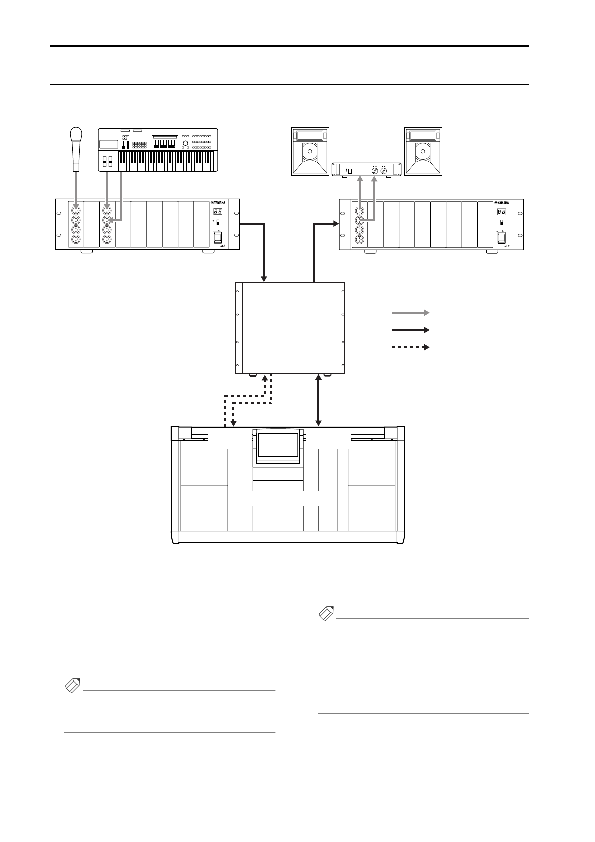
CS1D Operating Manual (Basic Operation)
Signal flow in the PM1D system
The following diagram shows the general signal flow within the PM1D system.
Mic Line device Speaker system foldback
12345678
AI8 analog input unit
INPUT UNIT NO.
PHANTOM MASTER
ON
+48V
OFF
POWER
ON/ OFF
ANALOG INPUT BOX
INPUT
1~10
3
CONTROL
I/O
OUTPUT
1
4
DSP1D-EX {DSP1D}
engine
2
CONTROL
I/O
DIGITAL I/O
CONSOLE
INPUT
OUTPUT
1~6
I/O
DIGITAL I/O
ENGINE A
1234567
AO8 analog output unit
Analog audio signal
Digital audio signal
Control signal
8
OUTPUT UNIT NO.
INPUT SELECTOR
A
B
POWER
ON/ OFF
ANALOG OUTPUT BOX
Console (CS1D)
1 The signals input to the AI8 analog input unit are AD
converted, and then sent as multi-channel digital
audio signals to the DSP1D-EX {DSP1D} engine.
2 The signals sent to the DSP1D-EX {DSP1D} engine
are processed by mixing, routing, EQ/dynamics/
effects.
3 In general, the operation of the engine and of the
input unit is controlled from the CS1D console.
Hint
The signals that are input from the 2-TRACK IN
DIGITAL jacks 1–6 and 2-TRACK IN ANALOG
jacks 1/2 of the CS1D can also be sent to the engine.
4 The signals processed by the engine are DA con-
verted by the output unit, and sent to the speaker
system, foldback system, or recording system.
Hint
Signals can also be output from the STEREO OUT
DIGITAL jacks or MONITOR OUT ANALOG jacks
of the CS1D.
When a DIO8 digital input/output unit is used, the
same unit will be used both as an input unit and output unit, so that the signal flow will be as shown on
the next page.
4
Page 77

OUTPUT
ADAT digital MTR
ADAT
OUTIN
DIGITAL I/O CARD
MODEL MY8-TD
DIO8 digital input/output unit
I/O UNIT ID
PORT B SELECTOR
5-8
1-4
Chapter 1. Introduction
INPUT
POWER
ON/ OFF
INPUT
1~10
DSP1D-EX {DSP1D}
engine
OUTPUT
1~6
5
Page 78

CS1D Operating Manual (Basic Operation)
Number of inputs/outputs and channel structure
The DSP1D-EX {DSP1D} engine provides INPUT connectors 1–10 for connecting input units, and OUTPUT connectors 1–6 for connecting output units.
DSP
x1x1
When the PM1D system is used in Standard mode, up to ten input units (maximum of 320 input connectors) and up to
six output units (maximum of 192 output connectors) are connected to one engine.
Input units
OUTPUT A
OUTPUT A
OUTPUT A
OUTPUT A
OUTPUT A
OUTPUT A
OUTPUT A
OUTPUT A
OUTPUT A
OUTPUT A
INPUT
1~10
DSP1D-EX {DSP1D}
OUTPUT
1~6
engine
Output units
INPUT A
INPUT A
INPUT A
INPUT A
INPUT A
INPUT A
DSP
x2x2
When the PM1D system is used in Mirror mode, up to ten input units (maximum of 320 input connectors) and up to six
output units (maximum of 192 output connectors) are connected to two engines.
Input units
OUTPUT B OUTPUT A
OUTPUT B OUTPUT A
OUTPUT B OUTPUT A
OUTPUT B OUTPUT A
OUTPUT B OUTPUT A
OUTPUT B OUTPUT A
OUTPUT B OUTPUT A
OUTPUT B OUTPUT A
OUTPUT B OUTPUT A
OUTPUT B OUTPUT A
INPUT
1~10
INPUT
1~10
DSP1D-EX {DSP1D}
DSP1D-EX {DSP1D}
OUTPUT
1~6
engine A
OUTPUT
engine B
Output units
INPUT A INPUT B
INPUT A INPUT B
INPUT A INPUT B
INPUT A INPUT B
INPUT A INPUT B
INPUT A INPUT B
1~6
6
Page 79

Chapter 1. Introduction
In either mode, the input connectors of an input unit must be assigned (patched) in the CS1D display to an input channel in order to be used. Similarly, in order to use the output connectors of an output unit, you must assign them in the
display to an output channel (MIX channel, MATRIX channel, STEREO A/B channel).
The following table shows the type and number of engines required when using the 48 channel model and 96 channel
model in Standard mode or Mirror mode, and the number of input/output connectors and channels that can be used.
Number of inputs/outputs and channel structure
Standard mode Mirror mode
Model 48 channel model 96 channel model 48 channel model 96 channel model
Engine DSP1D × 1 DSP1D-EX × 1 DSP1D × 2 DSP1D-EX × 2
Input connectors Maximum 320 Maximum 320 Maximum 320 Maximum 320
Output connectors Maximum 192 Maximum 192 Maximum 192 Maximum 192
Monaural input channels 48 96 48 96
Stereo input channels 4848
MIX channels 48 48 48 48
MATRIX channels 24 24 24 24
STEREO channels 2 (A, B) 2 (A, B) 2 (A, B) 2 (A, B)
Hint
The 96 channel model and 48 channel model differ in the number of available monaural input channels and stereo
input channels. However, they have the same number of MIX channels, MATRIX channels, and STEREO A/B output
channels.
In Mirror mode, one of the engines (A/B) is maintained as a backup, and you can manually switch between the units
to use either one or the other. Thus, the number of input/output connectors and channels is the same as in Standard
mode.
7
Page 80

CS1D Operating Manual (Basic Operation)
MIX buses/MATRIX buses
The PM1D system can send the input channel signals to MIX buses 1–48. The signals sent to a MIX bus is routed
through a MIX channel that provides EQ, comp, and delay, and is output from the respective connector that is patched to
MIX 1–48. At this time, you can choose to either fix the signal levels that are output from the input channels (FIX mode)
or allow them to vary (VARI mode). MIX buses that are set to FIX mode can be used as group buses, and MIX buses that
are set to VARI can be used as AUX buses.
In addition, the PM1D system has 24 independent MATRIX buses. Signals from MIX channels 1–48, STEREO A/B channels, and SUB IN can be mixed at the desired level and sent to a MATRIX bus. The signal sent to a MATRIX bus is routed
through a MATRIX channel that provides EQ, comp, and delay, and is output from the respective output connector that
is patched to MATRIX 1–24.
Scene memories/Libraries
The PM1D system can store the mix parameters of each channel and the settings of the entire PM1D system in memory
as a scene. Scenes are assigned a number consisting of an integer portion in the range of 00–99, and a decimal portion in
the range of .0–.9, for a total of 1,000 scenes from 00.0 to 99.9. (Ten of these scenes are read-only.)
Independently of scene memory, the PM1D system can store settings such as patch data, EQ data, compressor data, and
effect data in libraries for later reuse.
Word clock synchronization
In order for digital audio signals to be accurately transmitted and received, all components of the PM1D system and the
digital devices connected to the digital input/output units must be synchronized to the same word clock signal.
If any non-synchronized device is present, the input/output signals of that device may be muted, or may generate
click noise.
DSP
x1x1
In Standard mode, the internal clock of the engine is normally used as the word clock master, and the input/output units
and console will be synchronized to this. It is also possible to use an external clock generator as the master that supplies a
word clock to the engine, console, and input/output units.
DSP
x2x2
In Mirror mode, you can also switch to the other engine manually if the currently-used engine experiences difficulties. In
order to minimize the clock switching time in such cases, we recommend that you supply a word clock from an external
clock generator to the console and to engines A/B. Of course, switching will occur even without this type of supply
method.
Hint
For details on selecting the word clock master, refer to “CS1D Operation Manual (Start-up)” (→p.24) and to “CS1D
Reference Manual (Software)” (→p.44).
Hint
As an exception, the 2-TRACK IN DIGITAL jacks 1–6 of the CS1D console have built-in sample rate converters, and
will accept digital signals that are not synchronized with the PM1D system.
8
Page 81

Chapter 2. The user interfaces of the CS1D
This chapter introduces the various user interfaces that control the software of the CS1D console, and explains how to
use them.
About the user interfaces
The PM1D system is designed so that basic parameters such as channel adjustments and mixing can be controlled using
only the faders and encoders on the top panel of the CS1D. However if you wish to make more detailed settings, you will
need to access a specific function and edit the parameter value in software. The following pages explain the various interfaces used to control the software in the display.
User interfaces within the display
The following user interfaces are used within the display of the CS1D.
• Pointer
The arrow shown in the display is called the
“pointer.” The pointer is used to select the element
that you wish to control.
Pointer
• Cursor
The red frame shown in the display is called the “cursor.” When an on-screen element is enclosed by the
cursor, that element is selected for control.
Cursor
• Buttons
Buttons in the display are used to switch parameters
on/off, or to select one of multiple choices. Currently-on buttons are displayed in green, and buttons
that are off are displayed in gray.
Buttons turned on
Buttons turned off
• Knobs/faders/numerical boxes
Knobs/faders in the display are used to modify the
value of a parameter. The current value can be verified in the numerical box.
Knob
Numerical box
• Tabs
The screen names shown at the upper left of the display are called “tabs.” Tabs are used to switch between
different screens within the same function.
Tab
Fader
Numerical box
9
Page 82

CS1D Operating Manual (Basic Operation)
• Text input box
These boxes are used to input characters/numerals/
symbols when assigning a name to a channel or
scene, etc.
• Character palette
This is a virtual keyboard used to input characters/
numerals/symbols into a text input box.
• Scroll bar
When one screen is insufficient to display all of the
items, this bar is used to access the portion that is
currently not shown.
Scroll bar
• MENU button
This is a special button that accesses the function
menu that is the starting point for operations in the
display. With the exception of the function menu
itself and various popup windows, this button is
shown at the same location in all screens.
MENU button
10
Page 83

Chapter 2. The user interfaces of the CS1D
User interface on the top panel of the CS1D
The top panel of the CS1D provides the following controls used for operations in the display.
LCD FUNCTION ACCESS block
The LCD FUNCTION ACCESS block contains switches used to access the desired function or screen in the display.
LCD FUNCTION ACCESS
block
1
2
3
1 Global functions
These switches access functions that affect the entire
PM1D system.
2 Output functions
These switches access functions that affect the output
channels.
3 Input functions
These switches access functions that affect the input
channels.
Press the switch for the desired function, and the
screen for that function will appear in the display.
Hint
By holding down the [SHIFT/GRAB] switch and
pressing one of these LCD FUNCTION ACCESS
switches, you can cycle backward through the pages
within that function (the Page Back function). The
Page Back function will also operate if you continue
holding these switches.
11
Page 84

CS1D Operating Manual (Basic Operation)
Data entry block
The data entry block contains controllers used to modify
the settings and values in the display.
Data entry block
1
3
4
2
5
1 CURSOR [▲]/[▼]/[√]/[®] switches
These switches are used to move the cursor in the
display to the desired parameter.
6
2 [DEC/CANCEL]/[INC/OK] switches
These are used to increase or decrease the value of
the parameter at which the cursor is located in the
display. These switches can also be used instead of
the CANCEL button or OK button shown in the
window that asks you to confirm a Recall or Store
operation before it is executed.
3 [SHIFT/GRAB] switch
When the cursor in the display is located at a knobtype parameter that has a broad range of adjustment,
you can hold down this switch and use the [DEC/
CANCEL]/[INC/OK] switches or rotate the [DATA]
encoder to change the parameter value in larger
steps.
In some screens, you can hold down this switch and
use the CURSOR [▲]/[▼]/[√]/[®] switches to
move the cursor from its current location to another
area. For details refer to the explanations of each
screen in the reference manual (software section).
4 [ENTER] switch
This switch is used to turn on/off the button at the
cursor location, or to open a popup window.
5 [DATA] encoder
This is used to increase or decrease the value of the
parameter at which the cursor is located in the display. If you hold down the [SHIFT/GRAB] switch
while you rotate the [DATA] encoder, the parameter
value will change more rapidly.
6 Tr ack pad and left/right switches
This is used to move the pointer in the display, or to
select a specific parameter.
When you are operating a knob-type display parameter that has a broad range of adjustment, you can
hold down the right switch of the track pad and
operate the pad to change the parameter value in
larger steps.
External user interfaces
As necessary, the following external user interfaces can be added to the PM1D system.
• Mouse
A PS/2 compatible mouse can be connected to the
MOUSE connector on the rear panel/top panel of the
CS1D, and used in the same way as the track pad.
• Keyboard
A PS/2 compatible keyboard can be connected to the
KEYBOARD connector on the rear panel/top panel
of the CS1D, and used to input characters/numerals/
symbols in the same way as the character palette.
12
The function of each key is listed below. (Key layout
is according to the English-language keyboard.)
Key Function
PageDown
PageDown
← → ↑ ↓
Numeric keypad 4, 6, 2, 8
(NumLock key
= off)
Alt+PageUp
Same function as the [DEC/CANCEL]
switch of the data entry block
Same function as the [INC/OK] switch of
the data entry block
Same function as the [CURSOR]
switches
Same function as moving the [DATA]
encoder in the INC direction
Page 85

Key Function
Alt+PageDown
Return
Enter
Shift Same function as [SHIFT/GRAB] switch
Ctrl+←,
Ctrl+→
Ctrl+c
Ctrl+v
Insert
Delete
BackSpace
Ctrl+↑,
Ctrl+↓, Tab
Esc
Alt + 0~9,
-,=
Same function as moving the [DATA]
encoder in the DEC direction
Same function as [ENTER] switch
Same function as clicking the è buttons in the character palette
Same function as clicking the COPY
button in the character palette
Same function as clicking the PASTE
button in the character palette
Same function as clicking the INS button
in the character palette
Same function as clicking the DEL button in the character palette
Delete backward one character in the
text input box (backspace function)
Switch the object of editing in the text
input box
Same function as clicking the MENU
button (normal screen)
Same function as clicking the CANCEL
button (popup windows with a CANCEL
button). In screens with no CANCEL
button, the same function as clicking the
OK button or EXIT button.
Switch pages within the same screen
Chapter 2. The user interfaces of the CS1D
Identical types of connectors on the rear panel and
top panel cannot be used simultaneously. Only one
connector of each type can be used.
• Numeric keypad
If a PS/2 compatible numeric keypad is connected to
the NUM KEY connector located on the rear panel
or top panel of the CS1D, you can use the keypad to
input numbers and recall scenes.
The function of each key is as follows.
Key Function
0–9
Enter
Same function as the SCENE MEMORY
block [0]–[9] switches
Same function as the SCENE MEMORY
block [RECALL] switch
Same function as the SCENE MEMORY
+
block [▲/INC] switch + [ENTER] s witch (recall
the next-numbered scene)
Same function as the SCENE MEMORY
-
block [▼/DEC] switch + [ENTER] switch
(recall the previously-numbered scene)
/
Not used in the current version
*
13
Page 86

CS1D Operating Manual (Basic Operation)
Track pad
Tapping
Various basic operations
This section explains the basic operations performed in the CS1D display. In general, operations in the CS1D software
will consist of combinations of these actions.
Click
“Click” is the action of moving the pointer to a specific item in the screen, and pressing the left or right switch of the
track pad (or if using an external mouse, pressing the left or right mouse button). Clicking is used to turn an on-screen
button on/off, to move the cursor, or to make fine adjustments of a numeric value.
Hint
Mouse left click
Left switch
Click
If you use the [CURSOR] switches of the data entry
block to move the cursor to a specific item and press
the [ENTER] switch, the result will be the same as if
you had clicked that item. (The same is true if you
use the arrow keys or ENTER key of an external keyboard.)
Mouse right click
Hint
After moving the pointer to a specific item, you can
tap the track pad to produce the same result. (This is
Right switch
called “tapping.”)
To defeat this function, you must cancel tapping in
the display (UTILITY function PREFERENCE
Click
screen). (“CS1D Reference Manual (Software)”
→p.36)
Drag
“Drag” is the action of moving the pointer to a specific item in the screen, then pressing and holding the left or right
switch and sliding your finger up/down/left/right on the track pad. To drag using the mouse, press and hold the left or
right mouse button, and move it up/down/left/right. Dragging is used mainly to modify the value of an on-screen knob
or fader.
Track pad
Drag
Mouse
Track pad
Drag
Mouse
Drag
Left switch
While pressing
14
Drag
Right switch
While pressing
Page 87

Chapter 2. The user interfaces of the CS1D
Drag and drop
“Drag and drop” is the action of moving the pointer to a specific item in the screen, dragging it to another location in the
screen, and then releasing your finger. Drag and drop is used (for example) to copy EQ or dynamics processor settings to
another channel.
Scroll
When the number of items for display is greater than can be shown in a single screen, you can drag the box within the
scroll bar to view the hidden portion.
• Dragging the scroll bar box
Drag
You can also scroll the screen by clicking the vacant
portion of the scroll bar or the / buttons or
/ buttons located at the ends of the scroll bar.
• Using the [DEC/CANCEL]/[INC/OK] switches or
the [DATA] encoder to operate the scroll bar
If you place the cursor on a scroll bar box and press
the [DEC/CANCEL] switch or rotate the [DATA]
encoder counter-clockwise, the screen will scroll
toward the left (or upward, in the case of a vertical
scroll bar). If you press the [INC/OK] switch or
rotate the [DATA] encoder clockwise, the screen will
scroll toward the right (or downward, in the case of a
vertical scroll bar).
Hint
If the cursor is at the box of a scroll bar, you can hold
down the [SHIFT/GRAB] switch and rotate the
[DATA] encoder to produce the same result as pressing the button or button (depending on the
direction of rotation).
Click these buttons to move the
scroll bar box in the direction of
the arrow. Clicking / will
produce greater movement than
clicking / .
If you click here, the box in
the scroll bar will move in
large steps toward the side
you clicked, and the screen
will scroll correspondingly.
15
Page 88

CS1D Operating Manual (Basic Operation)
Accessing the desired screen
There are two ways to access the desired function/screen in the display.
Using the LCD FUNCTION ACCESS block
[Procedure]
1. Of the switches in the LCD FUNCTION ACCESS
block, press the switch for the desired function.
The last-operated screen of the corresponding function will be accessed.
2. To switch screens within the same function, repeatedly press the same switch as in step 1.
Most functions have several screens.
If you hold down the [SHIFT/GRAB] switch of the
data entry block and press the same switch as in step
1, you will return to the previous screen of the same
function.
Using the buttons within the display
[Procedure]
1. In any screen, click the MENU button.
When you click the MENU button, the function
menu screen will appear. When you wish to select a
specific screen from the display, you will start from
this screen.
Hint
The MENU button will be located at the same place
in all screens, with the exception of the function
menu itself and various popup windows.
2. In the function menu screen, click the button for
the desired function.
The last-operated screen of the corresponding function will be accessed.
3. If the function includes more than one screen, click
the tabs at the upper part of the screen to select the
desired screen.
16
Page 89

Chapter 2. The user interfaces of the CS1D
Button operations
Buttons within the display are used to turn specific parameters on/off, or to choose one of multiple choices. Buttons can
be operated in the following ways.
Using the track pad (mouse)
[Procedure]
1. Drag the track pad (mouse) to move the pointer to
the desired button.
Pointer
2. Use the left or right switch of the track pad (mouse)
to click the button.
The button will be switched on/off. (Alternatively,
the corresponding button will be selected.)
• Switching a button on/off
Using the data entry block switches /keyboard
[Procedure]
1. Use the [CURSOR] switches (or the arrow keys of
the keyboard) to move the cursor to the desired
button.
Cursor
Click
Hint
If tapping in the display is enabled (UTILITY function PREFERENCE screen), you can also click by
tapping the track pad. In this case, the operation will
be the same as if you pressed the left switch of the
track pad (mouse). (“CS1D Reference Manual (Soft-
ware)” →p.36)
2. Press the [ENTER] switch (or the ENTER key of the
keyboard).
The button will be switched on/off. (Alternatively,
the corresponding button will be selected.)
Selected button
17
Page 90

CS1D Operating Manual (Basic Operation)
Moving the cursor
Here’s how to move the cursor (red box) in order to select the display parameter that you wish to edit.
Moving the cursor
[Procedure]
1. Press a CURSOR [▲]/[▼]/[√]/[®] switch. The
cursor in the display will move in the direction of
the switch you pressed.
However, the cursor will not move if no parameter
exists in the direction of that switch.
Move to the adjacent grid
Moving the cursor from a scroll window
[Procedure]
1. Hold down the [SHIFT/GRAB] switch, and press a
CURSOR [▲]/[▼]/[√]/[®] switch.
The cursor will move out of the scroll window
(where which it was located) in the direction of the
switch you pressed.
This technique can be used in screens that have a
scroll window (e.g., the IN/OUT PATCH function
INSERT PATCH screen) or in screens that have a list
window (e.g., the SCENE function MEMORY
screen).
• Using the [SHIFT/GRAB] switch and the CUR-
SOR [√]/[®] switches to move the cursor
Hint
If the cursor is on a grid such as in the PATCH
screen, rotating the [DATA] encoder clockwise will
move the cursor toward the right, and rotating it
counterclockwise will move the cursor toward the
left. If you hold down the [SHIFT/GRAB] switch,
rotating the [DATA] encoder clockwise will move the
cursor downward, and rotating it counterclockwise
will move the cursor upward.
[SHIFT/GRAB] switch
+
CURSOR [®] switch
18
Page 91

Chapter 2. The user interfaces of the CS1D
Adjusting the value of a knob or fader
Knobs and faders within the display are used to adjust the value of specific parameters. Knobs and faders can be adjusted
in the following ways.
Using the track pad (mouse)
[Procedure]
1. Move the pointer to the desired knob/fader, and use
the left or right switch of the track pad (mouse) to
click the knob/fader.
The cursor will move to that location.
2. To increase or decrease the value in steps of one, use
the right switch or left switch of the track pad
(mouse) to click the knob/fader.
Clicking the right switch will increase the value by
one, and clicking the left switch will decrease the
value by one.
3. To increase or decrease the value continuously, use
the track pad (mouse) to drag the knob/fader.
You can change the value continuously by dragging
the knob or fader in the left/right or up/down direction. In the case of a knob with a broad range of
adjustment, you can drag while holding down the
right switch of the track pad (mouse). This makes
the value change more rapidly than when the left
switch is held down. This method is convenient
when you wish to change the value rapidly.
2. To increase or decrease the value in steps of one, use
the [DEC/CANCEL]/[INC/OK] switches (or keys
that have the same function as the [DEC/CANCEL]/[INC/OK] switches, such as the PageUp/
PageDown keys of your keyboard).
• Change the value in steps of 1
3. To raise or lower the value continuously, rotate the
[DATA] encoder.
Adjust the value of the fader
Adjust the value of the knob
Using the data entry block switches (keyboard)
and encoder
[Procedure]
1. Use the [CURSOR] switches (or the arrow keys of
the keyboard) to move the cursor to the desired
knob/fader.
• Move the cursor to a knob
• Change the value continuously
Hint
If the parameter being adjusted by the knob has a
broad range of adjustment, you can increase the rate
of change by holding down the [SHIFT/GRAB]
switch and using the [DEC/CANCEL]/][INC/OK]
keys or rotating the [DATA] encoder.
19
Page 92

CS1D Operating Manual (Basic Operation)
Assigning a name
The PM1D system allows you to assign names (long name, short name) to individual channels, and to assign titles to
scenes and libraries. For example, the screen shown below is the LIBRARY STORE popup window in which you can
name and store a library.
Characters can be input in this screen in the following ways.
• LIBRARY STORE popup window
1. Use the text palette (or the keyboard) to input characters.
When you click the text palette, the corresponding
character/symbol/numeral will be input to the text
input box, and the highlighted area will move to the
right.
• DEL button........ Delete the highlighted character.
The same result will occur if you
press the Delete key of the keyboard.
• CLEAR button... Erase all characters that had been
input in the text box.
2. Input the remaining characters in the same way.
Va r ious buttons within the text palette can be used
while entering text.
These buttons have the following functions.
• INS button..........Insert a space (blank) at the
highlighted area. The same result
will occur if you press the Insert
key of the keyboard.
20
Page 93

• √ ® buttons.......Move the highlighted area to left
or right.
• PASTE button ....The text string that had been
copied to the buffer by the COPY
button will be pasted.
• COPY button .....The specified text string will be
copied from the text box into the
buffer.
•
CAPS LOCK button
Switch between uppercase and
lowercase alphabetical characters. When this button is on,
uppercase characters can be
input.
Chapter 2. The user interfaces of the CS1D
3. When you have input the name, click the STORE
button.
The name that you input will be finalized, and saved
in the library.
Hint
The same type of screen will be displayed in the IN
PATCH/OUT PATCH function NAME screen where
you assign a name (long name, short name) to each
channel, and the basic operation is the same.
The number of characters that can be used will
depend on the item that you are attempting to save.
It is not possible to insert characters or move the
highlighted portion in excess of the maximum
length for each text string.
Hint
If you connect the keyboard of a personal computer,
you can input text from the keyboard.
It is not possible to paste into the file name field of
the FILE SAVE popup window.
21
Page 94

Chapter 3. Audio connections and patching
This chapter explains how to connect input/output devices such as mics and speaker systems to the input/output units
and to the CS1D console, and patch them to input channels and output channels.
The “CS1D Operation Manual (Basic Operation)” assumes that the components of the PM1D system are connected
appropriately, and that all components are operating correctly. For details on connecting the components of the
PM1D system and checking their operation, refer to the “CS1D Operation Manual (Start-up).”
Audio connections
This section explains how to make audio connections for the input/output units and the console.
Audio connections for an analog input unit
Tw o types of input card can be installed in the AI8 analog input unit: the LMY2-ML mic/line input card and the LMY4AD AD card. The two cards differ in specifications and number of channels.
• Mic/line input card (LMY2-ML)
The LMY2-ML provides two (A and B) XLR-3-31
(balanced) input jacks for each of input channels 1
and 2. However, only one jack (A or B) at a time can
be used for each channel. (You can switch between A
and B in the SELECTED INPUT CHANNEL block
or in the display.)
• LMY2-ML connection
12345678
AI8 analog input unit
Mic
Mic
MIC/Line-Eingangsplatine
(LMY2-ML)
SIGNAL
ANALOG IN
CH2A CH1B CH1A
CH2B
B
SIGNAL
MIC/LINE INPUT CARD
MODEL LMY2-ML
INPUT UNIT NO.
PHANTOM MASTER
ON
OFF
POWER
ON/ OFF
ANALOG INPUT BOX
+48V
Sources ranging from mics to line level devices can
be connected to these jacks.
The pin wiring is as follows.
• Input jack wiring
Male XLR plug
Hint
1 (ground)
3 (cold)
2 (hot)
If you wish to supply +48 V phantom power to the
connected device, turn on the PHANTOM MASTER
switch (located on the front panel of the AI8), and
also turn on the [+48V] switch for the corresponding
input channel (→p.46).
If different sets of audio sources (that you will not
use simultaneously) are connected to LMY2-ML
jacks 1A and 1B, and to 2A and 2B, they can share
input channels of different settings simply by switching between A and B on the CS1D console.
B
Synthesizer
22
Page 95

• AD card (LMY4-AD)
The LMY4-AD provides four channels of XLR-3-31
(balanced) input jacks that can be used simultaneously.
• LMY4-AD connections
12345678
AI8 analog input unit
AD-Platine (LMY4-AD)
INPUT UNIT NO.
PHANTOM MASTER
ON
OFF
POWER
ON/ OFF
ANALOG INPUT BOX
+48V
Chapter 3. Audio connections and patching
Rhythm
SIGNAL
machine
CH3 CH2 CH1
CH4
SIGNAL
SIGNAL
SIGNAL
AD CARD
The pin wiring is as follows.
• Input jack wiring
Male XLR plug
ANALOG IN
MODEL LMY4-AD
Synthesizer
1 (ground)
3 (cold)
2 (hot)
23
Page 96

CS1D Operating Manual (Basic Operation)
Audio connections for an analog output unit
An LMY4-DA DA card installed in the AO8 analog output unit provides four channels of XLR-3-32 (balanced) output
jacks.
• LMY4-DA connections
1234567
AO8 analog output unit
LMY4-DA DA-Platine
ANALOG OUT
8
OUTPUT UNIT NO.
INPUT SELECTOR
A
B
POWER
ON/ OFF
ANALOG OUTPUT BOX
DA CARD
CH4 CH3 CH2 CH1
MODEL LMY4-DA
SIGNAL SIGNAL SIGNAL SIGNAL
Speaker system
The pin wiring is as follows.
• Output jack wiring
Female XLR plug
2 (hot)
3 (cold)
1 (ground)
24
Page 97

Chapter 3. Audio connections and patching
Audio connections for a digital input/output unit
The DIO8 digital input/output unit can accommodate up to eight digital I/O cards or analog I/O cards, according to
your system. The following diagrams show examples of connecting the DIO8 to digital recorders in ADAT, Tascam, and
AES/EBU formats.
• Connecting an ADAT format digital device
I/O UNIT ID
DIO8 digital input/output unit
Digital-E/A-Platinen MY8-AT
DIGITAL OUTDIGITAL IN
ADAT
ADAT
PORT B SELECTOR
5-8
1-4
POWER
ON/ OFF
OUTIN
DIGITAL I/O CARD
MODEL MY8-AT
• Connecting an AES/EBU format digital device
I/O UNIT ID
DIO8 digital input/output unit
Digital-E/A-Platinen MY8-AE
AES/EBU
DIGITAL I/O CARD
MODEL MY8-AE
PORT B SELECTOR
5-8
1-4
POWER
ON/ OFF
• Connecting a Tascam format digital device
I/O UNIT ID
DIO8 digital input/output unit
Digital-E/A-Platinen MY8-TD
Interface (TDIF-1)
Tascam Digital Audio
WORD CLOCK OUT
WORDCLOCK IN
Tascam
DIGITAL I/O CARD
MODEL MY8-TD
8-TRACK DIGITAL
PORT B SELECTOR
5-8
1-4
POWER
ON/ OFF
DIGITAL I/O
AES/EBU
IN
00.00.00.00
DAT
AES/EBU
OUT
Digital audio workstation
• When connecting a digital device via a digital I/O
card installed in the DIO8, the PM1D system and the
digital device must be synchronized to the same
word clock. (If they are not synchronized, the input/
output signal of that device may be muted, or may
produce click noise.)
• For details on the settings required to use a digital
device as a slave, refer to the manual for that device.
• When using an MY8-AT card to handle ADAT for-
mat signals, synchronization may tend to be lost easily, depending on the device that is connected. For
more reliable synchronization, we recommend that
the word clock for the combination of digital audio
equipment you are using be taken from other than
the ADAT format connector.
25
Page 98

CS1D Operating Manual (Basic Operation)
Audio connections for the console
In the PM1D system, most of the signal processing is performed in the input/output units and in the engine, and the
console simply controls their operation. However as exceptions, the CS1D also has the following input/output jacks.
• 2-TRACK IN DIGITAL AES/EBU jacks (1–6)
These are AES/EBU (XLR-3-31) jacks for inputting
AES/EBU format digital sources from an external
device such as a CD player or DAT recorder.
• 2-TRACK IN DIGITAL COAXIAL jacks (1–2 only)
These are coaxial (RCA phono) jacks for inputting
consumer format (IEC60958) digital sources from an
external device such as a CD player or DAT recorder.
• 2-TRACK IN ANALOG L/R jacks (1–2)
These are XLR-3-31 (balanced) input jacks for inputting stereo analog signals from an external device.
For 2-TRACK IN DIGITAL AES/EBU jacks 1/2 and
2-TRACK IN DIGITAL COAXIAL jacks 1/2, only
one type of jack can be used simultaneously. The
type of jack that will be used can be selected in the
display (MON/CUE function 2TR IN screen).
• Audio connections for the console 1
STEREO OUT
DIGITAL
2-TRACK IN DIGITAL
• STEREO OUT DIGITAL AES/EBU jacks (A/B)
These are AES/EBU (XLR-3-32) jacks that digitally
output the STEREO A/B channel signals in AES/EBU
format.
• STEREO OUT DIGITAL COAXIAL jacks (A/B)
These are COAXIAL (RCA phono) jacks that digitally output the STEREO A/B channel signals in consumer format (IEC60958).
• MONITOR OUT ANALOG jacks (A/B)
These are XLR-3-32 (balanced) jacks that output the
monitor A/B signals.
• CUE OUT ANALOG jacks (A/B)
These are XLR-3-32 (balanced) jacks that output the
cue signals.
• Audio connections for the console 2
TALKBACK IN 2
MONITOR OUT
ANALOG
2-TRACK IN
ANALOG
AES
/EBU
COAXIAL
AES
/EBU
COAXIAL
A
B
00.00.00.00
DAT recorder
DAT
AES
/EBU
AES
/EBU
AES
/EBU
AES
/EBU
3
4
5
6
DIGITAL OUTDIGITAL IN
AES
/EBU
COAXIAL
AES
/EBU
COAXIAL
1
CUE OUT
ANALOG
2
L
R
A
L
R
B
L
R
1
L
R
2
L
R
Monitor system
ANALOG OUT
CD player
26
Cue system
Page 99

• TALKBACK IN 1 jack (top panel)
• TALKBACK IN 2 jack (rear panel)
These are XLR-3-31 (balanced) jacks for connecting
talkback mics. These two jacks can be used simultaneously.
• Audio connections for the console 3
CS1D top
panel
Talkback mic
Chapter 3. Audio connections and patching
TALKBACK IN 2
CS1D rear
panel
27
Page 100

CS1D Operating Manual (Basic Operation)
Patching
Simply connecting an external device to an input/output unit does not cause the signal to be input to (or output from)
the engine. In order to transfer signals to and from the engine, you must assign (patch) each connector of the input/output unit to a channel of the PM1D system.
Hint
As exceptions, patching is not necessary for the output jacks of the CS1D console itself (the STEREO OUT DIGITAL
AES/EBU, STEREO OUT DIGITAL COAXIAL, MONITOR OUT ANALOG, and CUE OUT ANALOG jacks).
Input channel patching
Here’s how to patch an input unit to an input channel, and assign a name.
[Procedure]
1. In the LCD FUNCTION ACCESS block, press the
INPUT [PATCH] switch several times to access the
following screen.
LCD FUNCTION ACCESS
block
INPUT [PATCH] switch
This is the INPUT PATCH screen, in
which you can patch the various
input jacks and the return signals
from the internal effects to the
desired input channel (monaural/
stereo).
28
 Loading...