

Yamaha Audio CP2000 User Manual

POWER AMPLIFIER
Owner’s Manual
POWER
TEMP
PROTECTION
POWER
ON OFF
Keep This Manual For Future Reference.
POWER AMPLIFIER
20
25
30 30
40
LLR
15
CLIP
10
LEVEL
6
3
0
–dB
15
20
25
40
10
6
3
0
R
E

WARNING: THIS APPARATUS MUST BE EARTHED
IMPORTANT
THE WIRES IN THIS MAINS LEAD ARE COLOURED IN
ACCORDANCE WITH THE FOLLOWING CODE:
GREEN-AND-YELLOW : EARTH
BLUE : NEUTRAL
BROWN : LIVE
As the colours of the wires in the mains lead of this apparatus may
not correspond with the coloured markings identifying the terminals in
your plug, proceed as follows:
The wire which is coloured GREEN and YELLOW must be
connected to the terminal in the plug which is marked by the letter E
or by the safety earth symbol or coloured GREEN and YELLOW.
The wire which is coloured BLUE must be connected to the terminal
which is marked with the letter N or coloured BLACK.
The wire which is coloured BROWN must be connected to the
terminal which is marked with the letter L or coloured RED.
* This applies only to products distributed by YAMAHA KEMBLE
MUSIC (U.K.) LTD.

Important Information
Please read the following before using the CP2000
Warnings
• Do not allow water to enter this unit or allow the unit to become wet. Fire or electrical
shock may result.
• Connect this unit’s power cord only to an AC outlet of the type stated in this Owner’s
Manual or as marked on the unit. Failure to do so is a fire and electrical shock hazard.
• Do not scratch, bend, twist, pull, or heat the power cord. A damaged power cord is a
fire and electrical shock hazard.
• Do not place heavy objects, including this unit, on top of the power cord. A damaged
power cord is a fire and electrical shock hazard. In particular, be careful not to place
heavy objects on a power cord covered by a carpet.
• Do not place a container with liquid or small metal objects on top of this unit. Liquid
or metal objects inside this unit are a fire and electrical shock hazard.
• If you notice any abnormality, such as smoke, odor, or noise, or if a foreign object or
liquid gets inside the unit, turn it off immediately. Remove the power cord from the AC
outlet. Consult your dealer for repair. Using the unit in this condition is a fire and electrical shock hazard.
• Should this unit be dropped or the cabinet be damaged, turn the power switch off,
remove the power plug from the AC outlet, and contact your dealer. If you continue
using the unit without heeding this instruction, fire or electrical shock may result.
Important Information
i
• If the power cord is damaged (i.e., cut or a bare wire is exposed), ask your dealer for a
replacement. Using the unit with a damaged power cord is a fire and electrical shock hazard.
• Do not remove the unit’s cover. You could receive an electrical shock. If you think internal inspection, maintenance, or repair is necessary, contact your dealer.
• Do not modify the unit. Doing so is a fire and electrical shock hazard.
Cautions
• When rack-mounting the unit, allow enough free space around the unit for normal
ventilation. This should be: 10 cm behind, and 2 cm above.
For normal ventilation during use, remove the rear of the rack or open a ventilation hole.
If the airflow is not adequate, the unit will heat up inside and may cause a fire.
• This unit has ventilation holes at the front and rear to prevent the internal temperature
rising too high. Do not block them. Blocked ventilation holes are a fire hazard.
• Clean the contacts of the phone plug before connecting it to the SPEAKERS jack of this
unit. Dirty contacts may generate heat.
• Use only speaker cables when connecting speakers to amplifier outputs. Using other
types of cables is a fire hazard.
• Hold the power cord plug when disconnecting it from an AC outlet. Never pull the
cord. A damaged power cord is a potential fire and electrical shock hazard.
• Do not touch the power plug with wet hands. Doing so is a potential electrical shock
hazard.
• Do not use this amplifier for any purpose other than driving loudspeakers.
CP2000—Owner’s Manual

ii
Contents
Package Contents
The CP2000 package should contain the following items. Contact your Yamaha dealer
if anything is missing.
• CP2000 Power Amplifier
• This manual
Trademarks
Yamaha is a trademark of Yamaha Corporation. All other trademarks are the property
of their respective holders and are hereby acknowledged.
Copyright
No part of this Owner’s Manual may be reproduced or distributed in any form or by any
means without the prior written authorization of Yamaha Corporation.
© 2000 Yamaha Corporation. All rights reserved.
Contents
1 Introduction . . . . . . . . . . . . . . . . . . . . . . . . . . . . . . . . 1
Welcome . . . . . . . . . . . . . . . . . . . . . . . . . . . . . . . . . . . . . . . . . . . . . . . . . . . . . . . . . . . 1
Front Panel . . . . . . . . . . . . . . . . . . . . . . . . . . . . . . . . . . . . . . . . . . . . . . . . . . . . . . . . . 2
Rear Panel . . . . . . . . . . . . . . . . . . . . . . . . . . . . . . . . . . . . . . . . . . . . . . . . . . . . . . . . . . 3
2 Hookup Examples . . . . . . . . . . . . . . . . . . . . . . . . . . . . 4
Stereo Hookup . . . . . . . . . . . . . . . . . . . . . . . . . . . . . . . . . . . . . . . . . . . . . . . . . . . . . . 4
Parallel Hookup . . . . . . . . . . . . . . . . . . . . . . . . . . . . . . . . . . . . . . . . . . . . . . . . . . . . . 5
Bridge Mode Hookup . . . . . . . . . . . . . . . . . . . . . . . . . . . . . . . . . . . . . . . . . . . . . . . . 6
3 Using the CP2000 . . . . . . . . . . . . . . . . . . . . . . . . . . . . 7
Installation . . . . . . . . . . . . . . . . . . . . . . . . . . . . . . . . . . . . . . . . . . . . . . . . . . . . . . . . . 7
Connecting Inputs . . . . . . . . . . . . . . . . . . . . . . . . . . . . . . . . . . . . . . . . . . . . . . . . . . . 7
Connecting Speakers . . . . . . . . . . . . . . . . . . . . . . . . . . . . . . . . . . . . . . . . . . . . . . . . . 9
Connecting S115 and S112 loudspeakers . . . . . . . . . . . . . . . . . . . . . . . . . . . . . . . . 11
Turning On the Power . . . . . . . . . . . . . . . . . . . . . . . . . . . . . . . . . . . . . . . . . . . . . . . 11
Protection System . . . . . . . . . . . . . . . . . . . . . . . . . . . . . . . . . . . . . . . . . . . . . . . . . . . 11
Daisy Chaining Inputs . . . . . . . . . . . . . . . . . . . . . . . . . . . . . . . . . . . . . . . . . . . . . . . 12
Troubleshooting . . . . . . . . . . . . . . . . . . . . . . . . . . . . . . . . . . . . . . . . . . . . . . . . . . . . 13
Appendix . . . . . . . . . . . . . . . . . . . . . . . . . . . . . . . . . . . 14
Specifications . . . . . . . . . . . . . . . . . . . . . . . . . . . . . . . . . . . . . . . . . . . . . . . . . . . . . . . 14
Dimensions . . . . . . . . . . . . . . . . . . . . . . . . . . . . . . . . . . . . . . . . . . . . . . . . . . . . . . . . 15
Block Diagram . . . . . . . . . . . . . . . . . . . . . . . . . . . . . . . . . . . . . . . . . . . . . . . . . . . . . . 16
CP2000—Owner’s Manual

1 Introduction
Welcome
Thank you for choosing the Yamaha CP2000 Power Amplifier. Based on a new
improved version of Yamaha’s
two-channel power amplifier, offering high-power, superb sonic performance, and reliability, all backed by the Yamaha tradition of excellence in professional audio.
CP2000 key features include
• 650 W+650 W into 4
• 2,000 W into 4
• Yamaha Speaker Processing matches the CP2000 to the Yamaha S115 and S112 loudspeakers.
• Three operating modes are provided: STEREO mode in which Channel L and Channel
R operate independently, PARALLEL mode in which the channels operate independently but are both fed from the Channel L inputs, and BRIDGE mode in which both
channels are combined to form a massive 2000 watt single-channel amplifier.
• Improved
• Compared to conventional designs, EEEngine ’s energy saving capabilities reduce power
consumption by up to 50% and cut heat generation by up to 35%.
• Built-in limiter prevents excessive output signal distortion, protecting both speakers
and eardrums.
• Electronically balanced XLR-type and 1/4" phone jack input connectors.
• 5-way binding posts and 1/4" phone jack output connectors.
• Signal and CLIP indicators on each channel provide signal presence and clip warning.
Ω
bridged, 1,300 W into 8
EEEngine technology using MOSFET output devices.
EEEngine amplifier technology, the CP2000 is a versatile
Ω
stereo, 450 W+450 W into 8
Ω
bridged.
Ω
stereo.
Introduction
1
• Relay-based protection system protects both amplifier and speakers if heatsink overheating occurs or a DC offset is detected at the outputs.
• TEMP indicator warns of heatsink overheating.
• Variable-speed low-noise fan regulates the system temperature even under the most
demanding conditions. While the CP2000 is idle, the fan stops for silent operation.
CP2000—Owner’s Manual
2
Chapter 1—Introduction
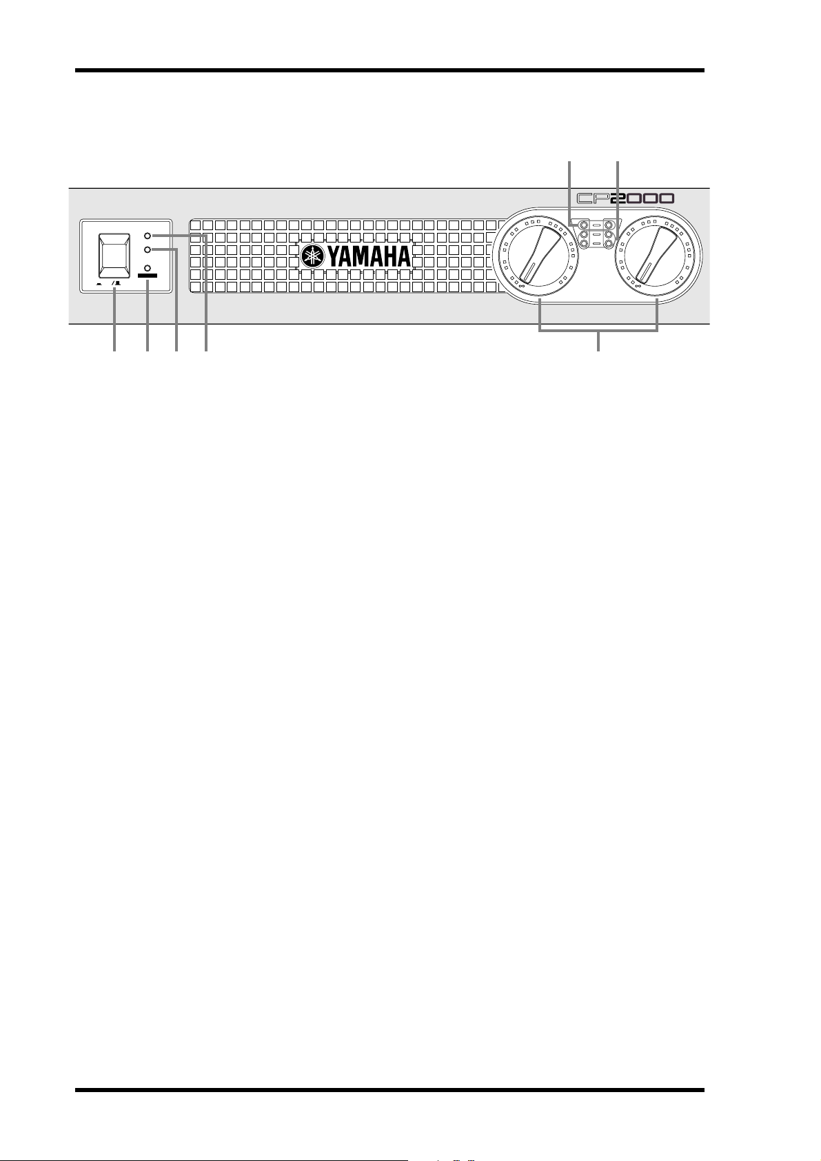
Front Panel
POWER
TEMP
PROTECTION
POWER
ON OFF
1
2 3 4
POWER switch
A
This is the main POWER switch. Press to turn on the amplifier; press again to turn off.
See “Turning On the Power” on page 11 for more information.
6
POWER AMPLIFIER
15
20
25
30 30
40
10
0
L
7
L
R
CLIP
LEVEL
6
3
–dB
5
15
20
25
40
10
6
3
0
R
B
POWER indicator
This indicator lights up when the CP2000 is turned on.
C
PROTECTION indicator
This indicator shows the status of the protection system. See “Protection System” on
page 11 for more information.
D
TEMP indicator
This indicator lights up if the temperature of the CP2000’s heatsinks exceed 85 degrees
Celsius. Note that this indicator only serves as a warning. It does not indicate operation
of the protection system.
E
Level controls
These controls are used to adjust the volume level of each channel. Since the gain of
each amplifier channel is fixed, these controls work by attenuating the input signal from
between –
∞
dB and 0 dB. They are detented controls, which means they can be set to
any one of 31 positions. Detents protect against accidental adjustment, allow repeatable
setting, and make it easy to set both channels to the same volume. Usually these controls
are set to maximum and volume levels are controlled from the source equipment, typically a mixer.
F
CLIP indicators
These indicators light up when a channel’s output signal distortion exceeds 1% (i.e.,
clipping). Output signal clipping is usually due to excessive input signal levels. If a channel’s output signal does clip, that channel’s limiter circuit is activated to prevent further
signal distortion. It’s okay for a CLIP indicator to light occasionally, but if it lights frequently, the LEVEL control should be turned down a little.
G
LEVEL indicators
These indicators show the output signal level of each channel. The green indicators
light up when the output voltage is 2 V or greater, while the yellow indicators light up
when it’s 20 V or greater.
CP2000—Owner’s Manual
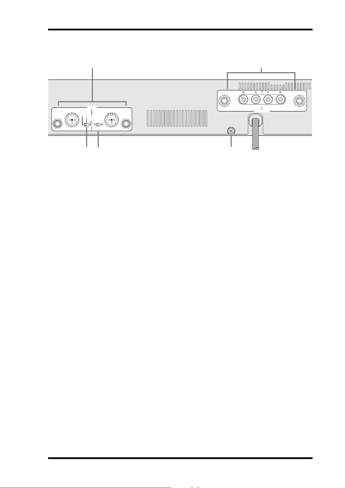
Rear Panel
1 4
CHANNEL R CHANNEL L
STEREO
132
2 3
INPUT
BRIDGE
PARALLEL
A
NEUTRIK
231
OFF ON
YAMAHA
SPEAKER PROCESSING
INPUTs
The inputs for each CP2000 channel comprise of one 1/4" phone jack and one
XLR-3-31-type connector. Both connectors are electronically balanced, although they
can also be used with unbalanced sources. See “Connecting Inputs” on page 7 for more
information. See also “Hookup Examples” on page 4.
(BRIDGE)
Rear Panel
(–)(+)
CHANNEL R CHANNEL L
BRIDGE
SPEAKERS
5
3
1
221
Since the phone jack and XLR-type connector on each channel are internally connected, either connector can be used to distribute the input signal to another amplifier.
See “Daisy Chaining Inputs” on page 12 for more information.
B
Mode switch
This switch is used to select the amplifier’s mode of operation: STEREO, PARALLEL,
or BRIDGE.
STEREO
—In this mode, which is typically used to amplify stereo sources, the L and R
channels operate independently.
PARALLEL
—In this mode, the L and R channels operate independently but the input
signal for both channels is sourced from the Channel L inputs. This mode is typically
used with a mono source and allows independent volume control of two sets of speakers.
BRIDGE
—In this mode, the L and R channels are combined to form a massive 2000
watt single-channel amplifier. The input signal is sourced from the Channel L inputs,
the volume level is set by using the Channel L LEVEL control, and the speakers are connected to the binding posts labelled BRIDGE.
C
YAMAHA SPEAKER PROCESSING switch
This switch is used to activate the special EQ processing that optimizes the CP2000 for
use with the Yamaha S115 and S112 loudspeakers. When other speakers are used, this
switch should be set to OFF. See “Connecting S115 and S112 loudspeakers” on page 11
for more information.
SPEAKERS connectors
D
The outputs for each CP2000 channel comprise of one 1/4" phone jack and one pair of
5-way binding posts. The 1/4" phone jacks accept 1/4" phone plugs, while the 5-way
binding posts offer several methods of connection, including single or double banana
plugs, spade lugs, or bare wires. See “Connecting Speakers” on page 9 for more information. See also “Hookup Examples” on page 4.
CP2000—Owner’s Manual
 Loading...