

Page 1
IMPORTANT
Check your power supply
Make sure that your local AC mains voltage matches the voltage
specified on the name plate on the bottom panel. In some areas a
voltage selector may be provided on the bottom panel of the main
keyboard unit near the power cord. Make sure that the voltage selector is set for the voltage in your area. The voltage selector is set at
240V when the unit is initially shipped. To change the setting use a
“minus” screwdriver to rotate the selector dial so that the correct voltage appears next to the pointer on the panel.
Page 2
SPECIAL MESSAGE SECTION
PRODUCT SAFETY MARKINGS: Yamaha electronic
products may have either labels similar to the graphics
shown below or molded/stamped facsimiles of these
graphics on the enclosure. The explanation of these graphics appears on this page. Please observe all cautions indicated on this page and those indicated in the safety instruction section.
CAUTION
RISK OF ELECTRIC SHOCK
DO NOT OPEN
CAUTION: TO REDUCE THE RISK OF ELECTRIC SHOCK.
DO NOT REMOVE COVER (OR BACK).
NO USER-SERVICEABLE PARTS INSIDE.
REFER SERVICING TO QUALIFIED SERVICE PERSONNEL.
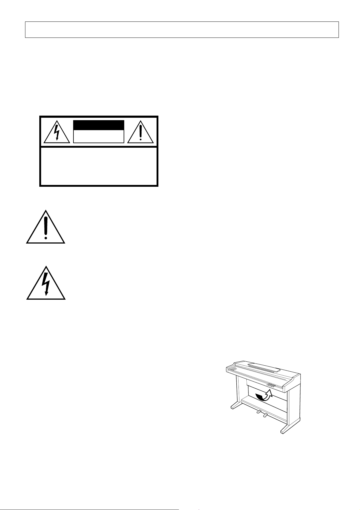
See bottom of Keyboard enclosure for graphic symbol markings
The exclamation point within the equilateral triangle is intended to alert the
user to the presence of important operating and maintenance (servicing) instructions in the literature accompanying the product.
ENVIRONMENTAL ISSUES: Yamaha strives to produce products that are both user safe and environmentally
friendly. We sincerely believe that our products and the
production methods used to produce them, meet these
goals. In keeping with both the letter and the spirit of the
law, we want you to be aware of the following:
Battery Notice: This product MAY contain a small nonrechargable battery which (if applicable) is soldered in
place. The average life span of this type of battery is approximately five years. When replacement becomes necessary, contact a qualified service representative to perform the replacement.
Warning: Do not attempt to recharge, disassemble, or
incinerate this type of battery. Keep all batteries away
from children. Dispose of used batteries promptly and as
regulated by applicable laws. Note: In some areas, the
servicer is required by law to return the defective parts.
However, you do have the option of having the servicer
dispose of these parts for you.
Disposal Notice: Should this product become damaged
beyond repair, or for some reason its useful life is considered to be at an end, please observe all local, state, and
federal regulations that relate to the disposal of products
that contain lead, batteries, plastics, etc.
The lightning flash with arrowhead
symbol, within the equilateral triangle,
is intended to alert the user to the presence of uninsulated “dangerous voltage” within the product’s enclosure that
may be of sufficient magnitude to constitute a risk of electrical shock.
IMPORTANT NOTICE: All Yamaha electronic products are tested and approved by an independent safety
testing laboratory in order that you may be sure that when
it is properly installed and used in its normal and customary manner, all foreseeable risks have been eliminated.
DO NOT modify this unit or commission others to do so
unless specifically authorized by Yamaha. Product performance and/or safety standards may be diminished.
Claims filed under the expressed warranty may be denied
if the unit is/has been modified. Implied warranties may
also be affected.
SPECIFICATIONS SUBJECT TO CHANGE: The
information contained in this manual is believed to be
correct at the time of printing. However, Yamaha reserves
the right to change or modify any of the specifications
without notice or obligation to update existing units.
NOTICE: Service charges incurred due to lack of knowledge relating to how a function or effect works (when the
unit is operating as designed) are not covered by the
manufacturer’s warranty, and are therefore the owners
responsibility. Please study this manual carefully and consult your dealer before requesting service.
NAME PLATE LOCATION: The graphic below indicates the location of the name plate. The model number,
serial number, power requirements, etc., are located on
this plate. You should record the model number, serial
number, and the date of purchase in the spaces provided
below and retain this manual as a permanent record of
your purchase.
Model _____________________________________
92-469 1
Serial No. __________________________________
Purchase Date ______________________________
Page 3
PRECAUTIONS
PLEASE READ CAREFULLY BEFORE PROCEEDING
* Please keep these precautions in a safe place for future reference.
WARNING
Always follow the basic precautions listed below to avoid the possibility of serious injury or even death from electrical shock,
short-circuiting, damages, fire or other hazards. These precautions include, but are not limited to, the following:
• Do not open the instrument or attempt to disassemble the internal parts
or modify them in any way. The instrument contains no user- serviceable
parts. If it should appear to be malfunctioning, di scontinue use immediately and have it inspected by qualifi ed Yamaha service personnel.
• Do not expose the instrument to rain, use it near water or in damp or wet
conditions, or place containers on it containi ng liqui ds which might spill
into any openings.
• If the power cord or plug becomes frayed or damaged, or if there is a
sudden l oss of sound during use of the i nstrument, or if any u nusual smell s
or sm oke shoul d app ear to be caused by i t, imm edi ately turn off the power
CAUTION
Always follow the basic precautions listed below to avoid the possibility of physical injury to you or others, or damage to the
instrument or other property. These precautions include, but are not limited to, the following:
switch, disconnect the electric plug from the outlet, and have the instrument inspected by qualifi ed Yamaha service personnel.
• Only use the voltage specified as correct for the instrument. The required
voltage is printed on the name plate of the instrument.
• Before cleani ng the instrument, always remove the electric pl ug from the
outlet. Never insert or remove an electric plug with wet hands.
• Check the electric pl ug periodically and remove any dirt or dust whi ch
may have accumulated on it.
• Do not place the power cord near heat sources such as heaters or radiators, and do not excessively bend or otherwise damage the cord, pl ace
heavy objects on it, or pl ace it in a position where anyone could walk on,
trip over, or rol l anything over it.
• When removing the electric plug from an outlet, always hold the plug
itself and not the cord. Pulling by the cord can damage it.
• Do not connect the instrument to an electrical outlet usi ng a multipl econnector. Doing so can result i n l ower sound quality, or possibly cause
overheating in the outlet.
• Remove the electric plug from the outl et when the instrument is not to be
used for extended periods of time, or during electrical storms.
• Before connecting the instrument to other electronic components, turn off
the power for all components. Before turni ng the power on or off for all
components, set all volume levels to minimum.
• Do not expose the instrument to excessive dust or vi brations, or extreme
cold or heat (such as in direct sunlight, near a heater, or in a car duri ng the
day) to prevent the possibility of panel disfiguration or damage to the
internal components.
• Do not use the instrument near other electri cal products such as televisions, radios, or speakers, since this mi ght cause interference which can
affect proper operation of the other products.
• Do not place the instrument in an unstable position where it might accidentally fall over.
• Before moving the instrument, remove all connected cables.
• When cleaning the instrument, use a soft, dry cloth. Do not use paint
thinners, sol vents, cleaning fluids, or chemical-impregnated wiping cloths.
Also, do not place vinyl, plastic or rubber objects on the i nstrument, since
this might discolor the panel or keyboard.
• Do not rest your weight on, or place heavy objects on the instr ument, and
do not use excessive force on the buttons, switches or connectors.
• Do not pl ace the instrument against a wall (allow at least 3 cm/one-inch
from the wall), since this can cause inadequate air circul ation, and possibly result in the instrument overheating.
• Read carefully the attached documentation explaining the assembly process. Failure to assemble the instrument i n the proper sequence might
result in damage to the instrument or even injury.
• Do not operate the instrument for a long period of time at a high or uncomfortable volume level, since this can cause permanent hearing l oss. If
you experience any hearing loss or ringing in the ears, consult a physician.
■USING THE BENCH (if included)
• Do not pl ay carelessly wi th or stand on the bench. Usi ng it as a tool or
step-l adder or for any other purpose might result in accident or injury.
• Only one person should sit on the bench at a time, in order to prevent the
possibility of accident or injury.
• If the bench screws become l oose due to extensive long- term use, tighten
them periodically using the included tool.
Yamaha cannot be held responsible for damage caused by improper use or modifications to the instrument.
Always turn the power off when the instrument is not in use.
CLP-810S
3
Page 4
Introduction
Thank you for choosing a Yamaha CLP-810S Clavinova. Your Clavinova is a fine musical instrument
that employs advanced Yamaha music technology. With the proper care, your Clavinova will give you many
years of musical pleasure.
● Stereo sampling of the acoustic piano and
Yamaha’s AWM (Advanced Wave Memory)
technology offers unmatched realism and expressive power.
● Piano-like touch response provides extensive
● The digital reverb effect adds extra depth and
expressiveness to the Clavinova’s sound.
● With MIDI compatibility and a range of MIDI
functions, the Clavinova can easily be incorporated into advanced MIDI systems.
expressive control and outstanding playability.
In order to make the most of your Clavinova’s performance potential and features, we urge you to read
this Owner’s Manual thoroughly, and keep it in a safe place for later reference.
Contents
The Control Panel ............................................................................................5
Music Stand .....................................................................................................6
Playing the Clavinova .....................................................................................7
Playing the Demonstration Tunes ..................................................................8
Reverb .............................................................................................................9
The Pedals .......................................................................................................9
●
Damper (Right) Pedal .....................................................................9
●
Soft (Left) Pedal ..............................................................................9
Transposition .................................................................................................10
Tuning............................................................................................................. 11
●
Tuning Up......................................................................................11
●
Tuning Down ................................................................................. 11
●
To Restore Standard Pitch ............................................................ 11
MIDI Functions ..............................................................................................12
●
A Brief Introduction to MIDI ...........................................................12
●
MIDI Transmit & Receive Channel Selection ................................12
●
Local Control ON/OFF ..................................................................13
Troubleshooting .............................................................................................14
Options & Expander M odules ......................................................................14
MIDI Data Format..........................................................................................15
MIDI Implementation Chart..........................................................................17
Keyboard Stand Assembly..........................................................................18
Specifications...............................................................................................24
Included Accessories
● Owner’s Manual
● Bench (included or optional depending on locale)
CLP-810S
4
○○○○○○○○○○○○○○○○○○○○○○○○○○○○○○○○○○○○○○○○○○○○○○○○○○○○○○○
Page 5
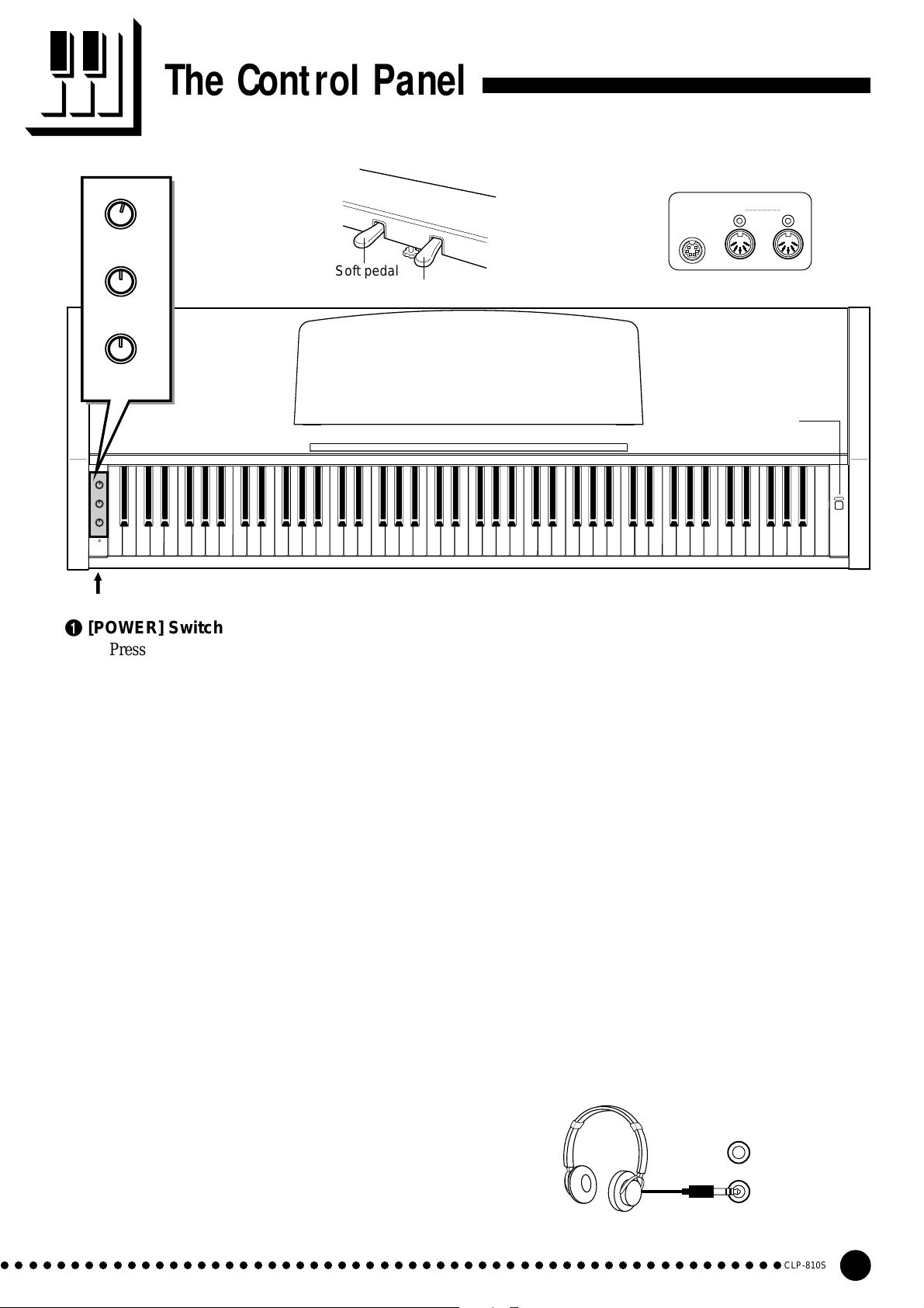
The Control Panel
OFF ON
2
VARIATION
Soft pedal
3
MIN MAX
REVERB
4
MIN MAX
MASTER
VOLUME
OFF ON
VARIATION
MIN MAX
REVERB
MIN MAX
MASTER
VOLUME
POWER
8
PHONES Jacks (Bottom panel)
B0A0G0F0E0D0C0B-1A-1
C1 D1 E1 F1 G1 A1 B1 C2 D2 E2 F2 G2 A2 B2 C3 D3 E3 F3 G3 A3 B3 C4 D4 E4 F4 G4 A4 B4 C5 D5 E5 F5 G5 A5 B5 C6
Damper pedal
1 [POWER] Switch
Press the [POWER] switch once to turn the power
ON, a second time to turn the power OFF. When the
power is turned ON, the POWER indicator (located
to the left of the keyboard) will light.
2 [VARIATION] selector
With the [VARIATION] selector in the OFF
position, the CLP-810S produces its normal piano
voice. In the ON position, a variation of the piano
voice is produced (page 7).
3 [REVERB] control
The [REVERB] control adjusts the amount of
reverb added to the Clavinova’s sound — see page 9
for details.
4 [MASTER VOLUME] Control
The [MASTER VOLUME] control adjusts the
volume (level) of sound produced by the Clavinova’s
internal stereo sound system. The [MASTER VOL-
UME] control also adjusts headphone volume when a
pair of headphones is plugged into the PHONES jack
(page 7).
5
Rear Panel
MIDI
IN OUT
PEDAL
67
1
D6 E6 F6 G6 A6 B6 C7
6 PEDAL Jack
This terminal is for connecting the pedal cord
from the pedal box (refer to the “Keyboard Stand
Assembly” on page 22).
7 MIDI IN and OUT Connectors
The MIDI IN connector receives MIDI data from
an external MIDI device (such as the DOU-10 Disk
Orchestra Unit) which can be used to control the
Clavinova. The MIDI OUT connector transmits MIDI
data generated by the Clavinova (e.g. note and
velocity data produced by playing the Clavinova
keyboard).
More details on MIDI are given in “MIDI Functions” on page 12.
8 PHONES Jacks
(Bottom Panel)
Two sets of standard stereo headphones can be
plugged in here for private practice or late-night
playing. The internal speaker system is automatically
shut off when a pair of headphones is plugged into
either of the PHONES jacks.
POWER
5 Pedals
The CLP-810S’s soft (left) and damper (right)
pedals provide a range of expressive control capabilities similar to the pedal functions on an acoustic
piano. See page 9 for details.
○○○○○○○○○○○○○○○○○○○○○○○○○○○○○○○○○○○○○○○○○○○○○○○○○○○○○○○○
CLP-810S
5
Page 6
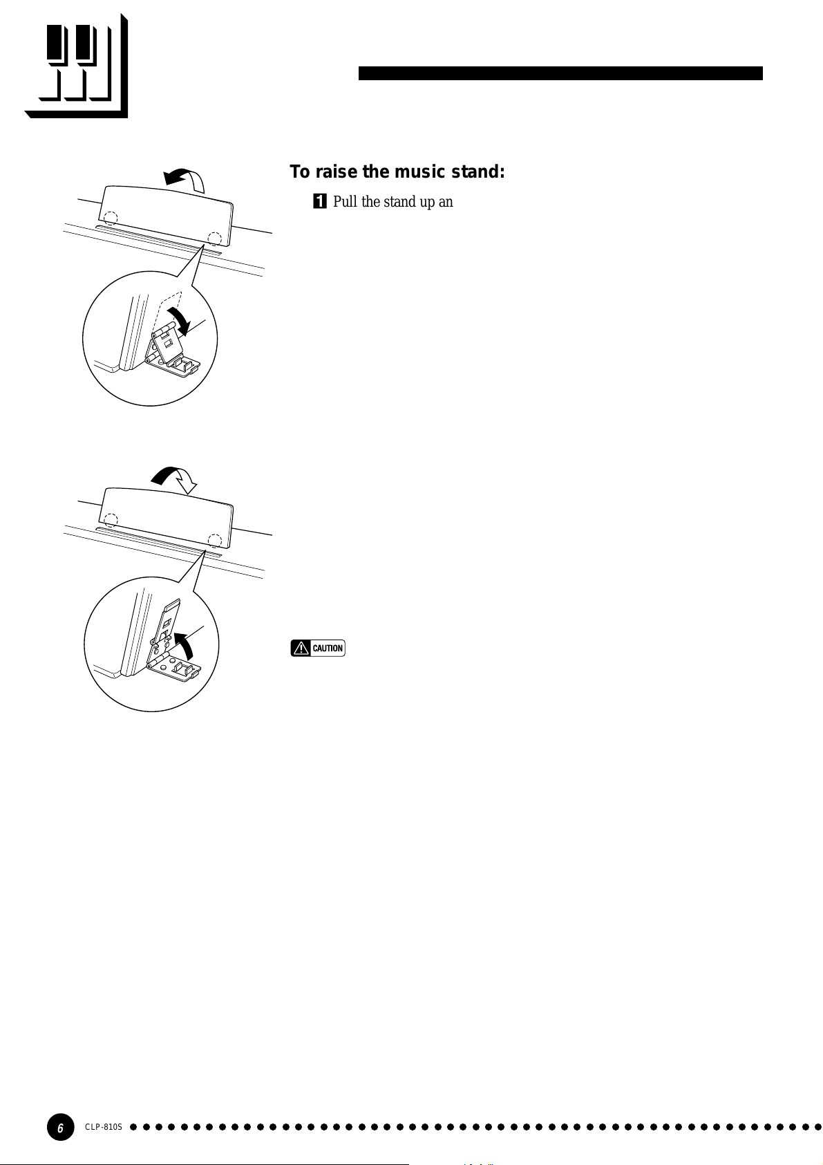
Music Stand
To raise the music stand:
ZPull the stand up and toward yourself as far as it will go.
XFlip down the two metal supports at the left and the right on the rear
CLower the music stand so that it rests on the metal supports.
As shown in the illustration, the angle of the music stand can be set in one
of three positions, according to the position of the metal supports. Set the left
and right metal supports to the same position.
of the music stand.
To lower the music stand:
ZPull the music stand toward yourself as far as it will go.
XRaise the two metal supports (at the rear of the stand).
CGently lower the music stand backward until it is all the way down.
• Do not try to use the music stand in a half-raised position.
When lowering the stand, do not release your hands from the music stand
until it is all the way down.
CLP-810S
6
○○○○○○○○○○○○○○○○○○○○○○○○○○○○○○○○○○○○○○○○○○○○○○○○○○○○○○○
Page 7
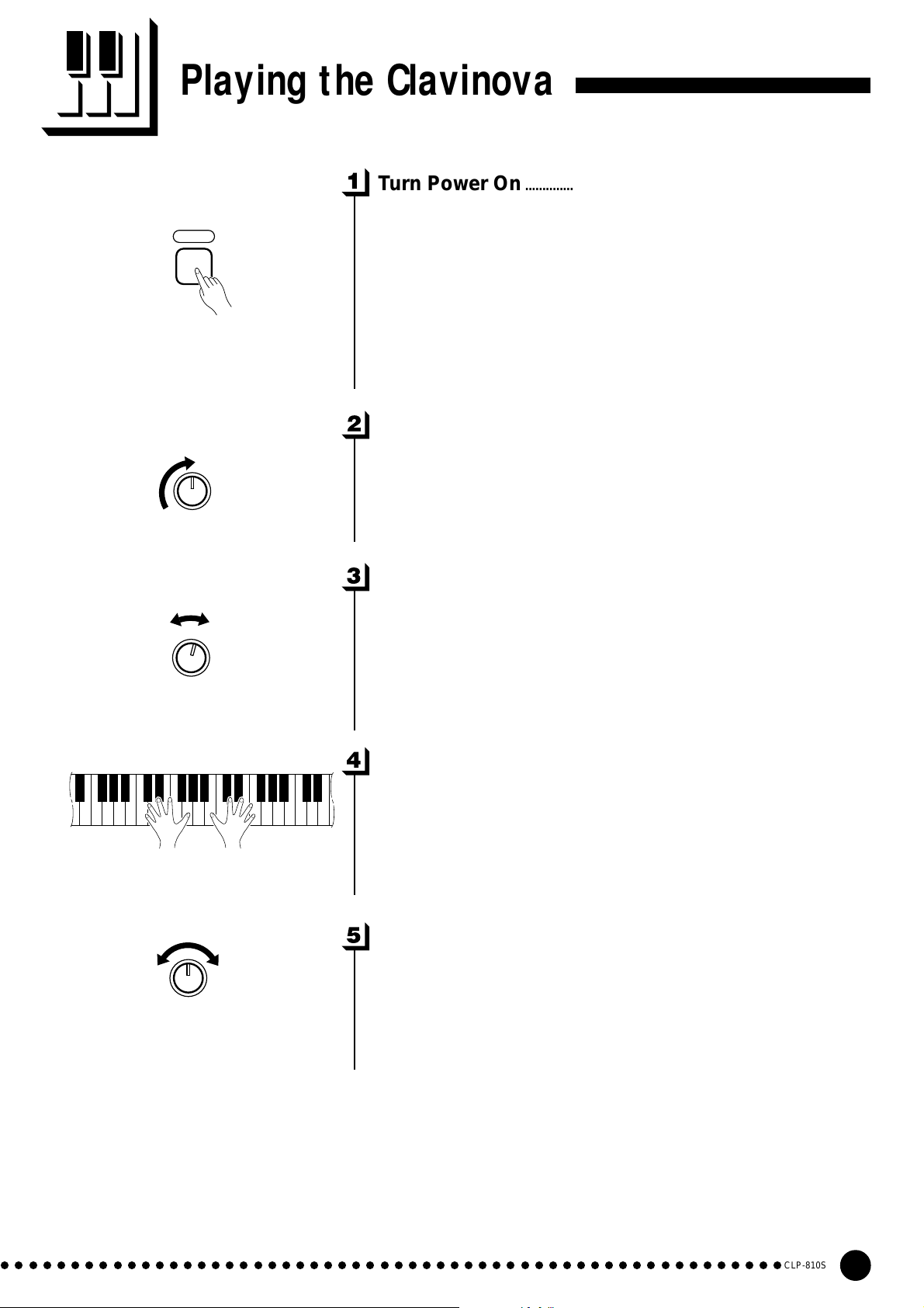
Playing the Clavinova
Turn Power On..................................................................................................
After making sure that the Clavinova’s AC cord is properly plugged
POWER
MIN MAX
MASTER
VOLUME
into the Clavinova itself and plugged into a convenient AC wall outlet,
press the [POWER] switch located to the right of the keyboard to turn
the power ON. In some areas a plug adaptor may be provided to match
the pin configuration of the AC wall outlets in your area.
When the power is turned ON, the POWER indicator located to the
left of the keyboard will light.
Set the Volume..................................................................................................
Initially set the [MASTER VOLUME] control about half way
between the “MIN” and “MAX” settings. Then, when you start playing,
re-adjust the [MASTER VOLUME] control for the most comfortable
listening level.
OFF ON
VARIATION
MIN MAX
REVERB
Select the Normal or Variation Voice........................................
Use the [VARIATION] selector to select the Clavinova’s normal or
variation voice.
In the OFF position, the keyboard’s normal piano voice is selected.
In the ON position, a variation of the keyboard’s piano voice is selected.
Play................................................................................................................................
The Clavinova offers keyboard touch response, so the volume and
timbre of notes played can be controlled according to how “hard” you
play the keys.
Add Reverb as Required........................................................................
With the [REVERB] control, you can add a desired amount of
reverb to the Clavinova’s sound (page 9).
○○○○○○○○○○○○○○○○○○○○○○○○○○○○○○○○○○○○○○○○○○○○○○○○○○○○○○○○
CLP-810S
7
Page 8
A-1C
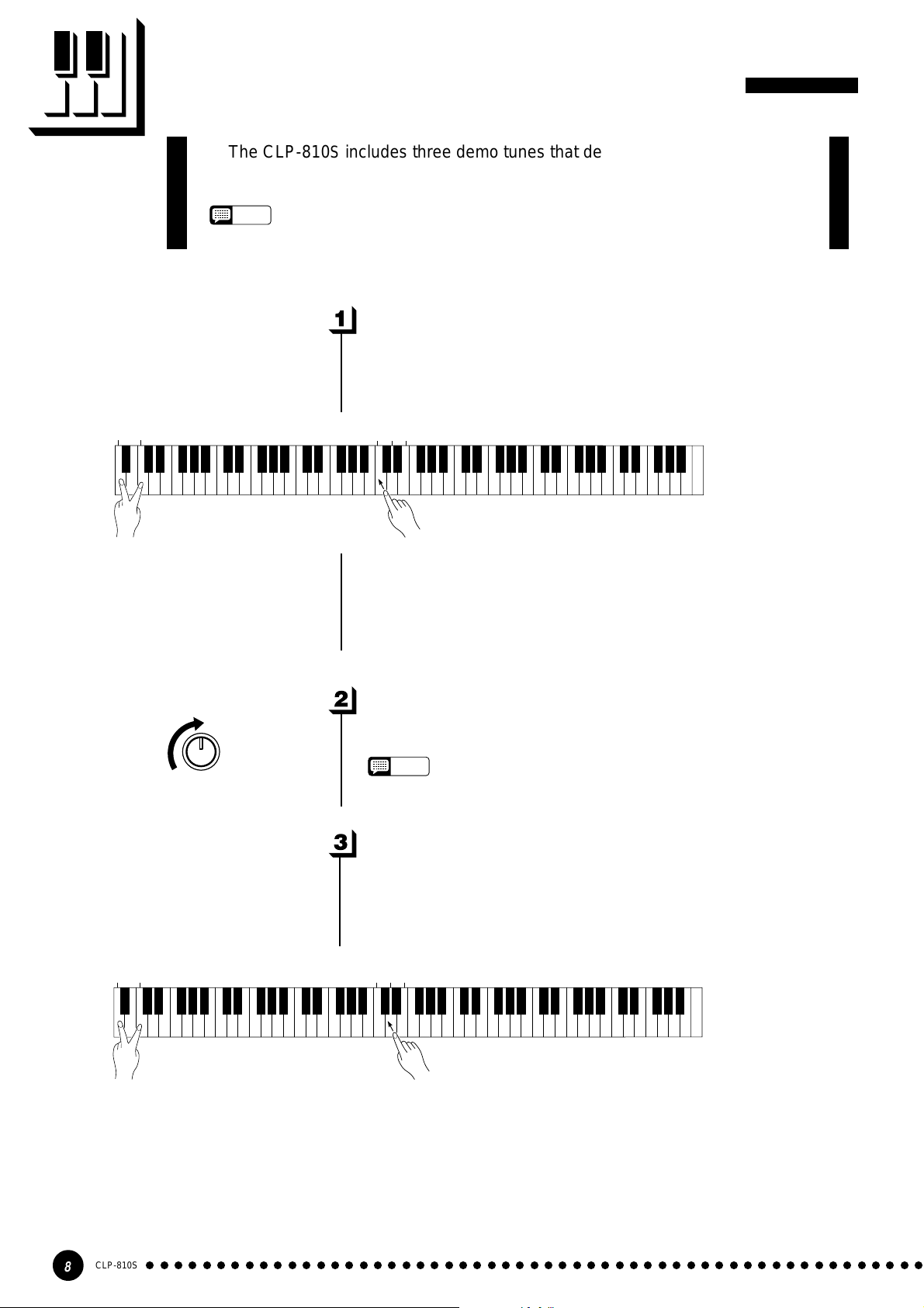
Playing the Demonstration Tunes
The CLP-810S includes three demo tunes that demonstrate its sound capa-
bilities. Here is how you can select and play the demo tunes:
NOTE
• No MIDI reception occurs in the demo song mode.
• The demo song data is not transmitted via the MIDI connectors.
Select and Start a Demo Tune .........................................................
While simultaneously holding the A-1 and C0 keys, press either C3,
D3 or E3 to select and start the corresponding demo tune. Starting with
the selected tune, the demo tunes will play in sequence until stopped.
0
C3D3E
3
A-1C
0
MIN MAX
MASTER
VOLUME
● The Demo Tunes
• C3 key:...... Fantaisie Impromptu / F.F.Chopin
• D3 key:...... Für Elise / L.v.Beethoven
• E3 key:......Perpetuum mobile (Sonata No.1) / C.M.v.Weber
Set the Volume..................................................................................................
Use the [MASTER VOLUME] control to adjust the volume.
NOTE
• You can play along with the demo tune on the keyboard.
Stop the Demo ..................................................................................................
To stop playback of the demo tune, simultaneously hold the A-1 and
C0 keys, and press any of the C3, D3 or E3 keys. Playback of the demo
tune will stop.
3
C3D3E
CLP-810S
8
○○○○○○○○○○○○○○○○○○○○○○○○○○○○○○○○○○○○○○○○○○○○○○○○○○○○○○○
Page 9
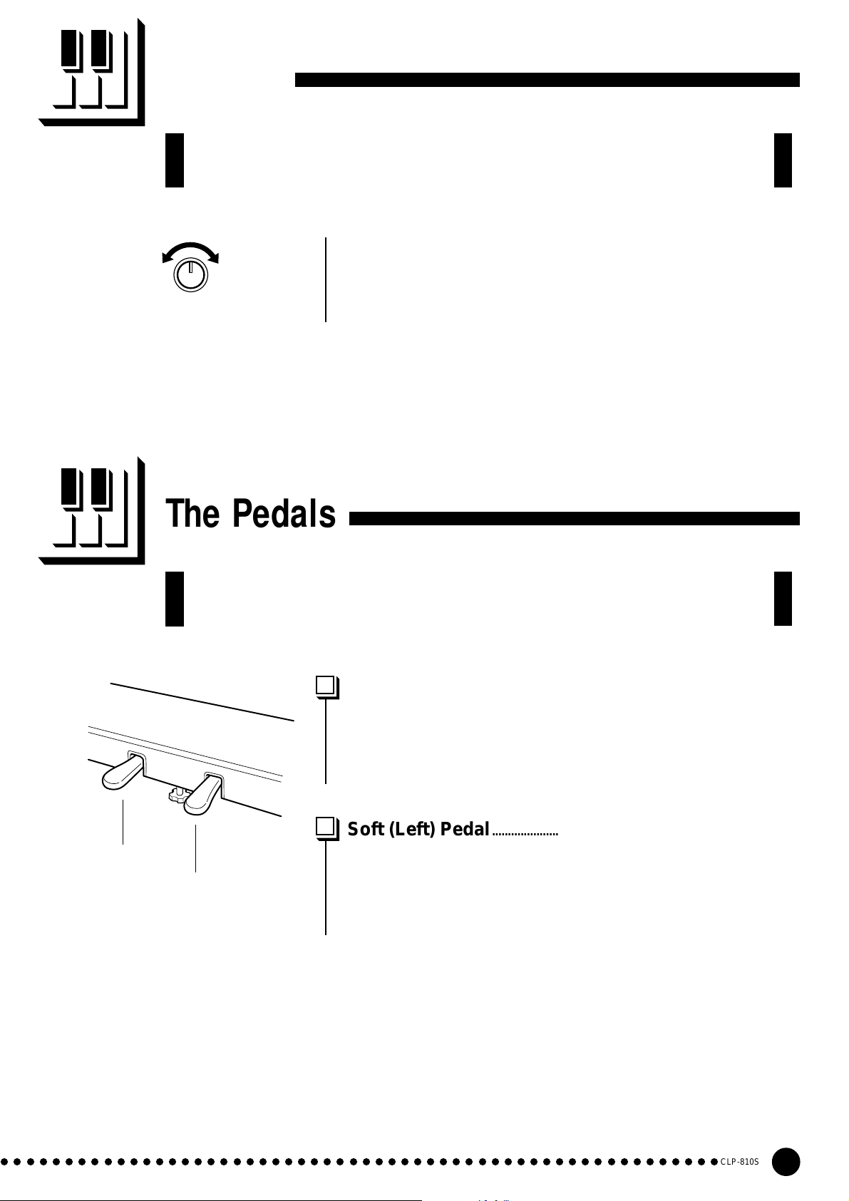
Reverb
The [REVERB] control lets you adjust the amount of digital reverb effect that
you can add for extra depth and expressive power.
Adjust the reverb depth using the [REVERB] control. The depth
range is from MIN to MAX. The MIN setting produces no effect, while
MIN MAX
REVERB
the MAX setting produces maximum reverb depth.
Soft pedal
The Pedals
The CLP-810S has two foot pedals that produce a range of expressive ef-
fects similar to those produced by the pedals on an acoustic piano.
Damper (Right) Pedal................................................................................
The damper pedal functions in the same way as a damper pedal on
an acoustic piano. When the damper pedal is pressed notes played have
a long sustain. Releasing the pedal immediately stops (damps) any
sustained notes.
Soft (Left) Pedal...............................................................................................
The soft pedal reduces the volume and slightly changes the timbre of
Damper pedal
notes played while the pedal is pressed. The soft pedal will not affect
notes which are already playing when it is pressed.
○○○○○○○○○○○○○○○○○○○○○○○○○○○○○○○○○○○○○○○○○○○○○○○○○○○○○○○○
CLP-810S
9
Page 10

Transposition
The Clavinova’s TRANSPOSE function makes it possible to shift the pitch of
the entire keyboard up or down in semitone intervals up to a maximum of six
semitones. “Transposing” the pitch of the Clavinova keyboard facilitates playing
in difficult key signatures, and you can easily match the pitch of the keyboard to
the range of a singer or other instrumentalist.
The A-1 and C#0 keys plus keys F#2 through F#3 on the keyboard are used for transposition.
Z Simultaneously press and hold the A-1 and C#0 keys.
X Press any key between F#2 and F#3 according to the desired
amount of transposition.*
C Release the A-1 and C#0 keys.
3
C
A-1C#
F#
0
2
F#
3
-6 -4 -2 +1
-5 -3 -1 0 +2 +4 +5
Transpose
down.
Normal
pitch.
+3 +6
Transpose
up.
* Pressing the C3 key produces normal keyboard pitch. Pressing the
key to the left of C3 (=B2) transposes the pitch of the keyboard
down a semitone, the next key to the left (=Bb2) transposes down a
whole tone (two semitones), etc., down to the F#2 key which
transposes down 6 semitones. Upward transposition is accomplished in the same way using the keys to the right of C3, up to F#3
which transposes up 6 semitones.
NOTE
• Notes below and above the A-1 — C7 of the Clavinova sound one
octave higher and lower, respectively.
10
CLP-810S
○○○○○○○○○○○○○○○○○○○○○○○○○○○○○○○○○○○○○○○○○○○○○○○○○○○○○○○
Page 11

Tuning
-1
A-1B
Tuning makes it possible to adjust the pitch of the Clavinova over a 427.0 Hz
… 453.0 Hz (corresponding to the A3 note’s Hz) range in approximately 0.2
Hertz intervals. Pitch control is useful for tuning the Clavinova to match other
instruments or recorded music.
Tuning Up...............................................................................................................
ZTo tune up (raise pitch), hold the A-1 and B-1 keys simultaneously .
XPress any key between C3 and B3. Each time a key in this range is
pressed the pitch is increased by approximately 0.2 Hz.
CRelease the A-1 and B-1 keys.
3
3
C
B
Tuning Down.......................................................................................................
ZTo tune down (lower pitch), hold the A-1 and A#-1 keys simulta-
neously .
XPress any key between C3 and B3. Each time a key in this range is
pressed the pitch is decreased by approximately 0.2 Hz.
-1
A#
-1
A
CRelease the A-1 and A#-1 keys.
3
C
3
B
To Restore Standard Pitch* ................................................................
ZTo restore standard pitch (A3 = 440 Hz), hold the A-1, A#-1 and
B-1 keys simultaneously.
XPress any key between C3 and B3.
CRelease the A-1, A#-1 and B-1 keys.
* Standard pitch (A3 = 440 Hz) is set when the [POWER] switch is
-1
A#
-1
A-1B
○○○○○○○○○○○○○○○○○○○○○○○○○○○○○○○○○○○○○○○○○○○○○○○○○○○○○○○○
initially turned ON.
3
3
C
B
CLP-810S
11
Page 12

MIDI Functions
● A Brief Introduction to MIDI
MIDI Cable
MIDI INMIDI OUT
DOU-10
Clavinova
MIDI, the Musical Instrument Digital Interface, is a worldstandard communication interface that allows MIDI-compatible
musical instruments and equipment to share musical information
and control one another. This makes it possible to create “systems”
of MIDI instruments and equipment that offer far greater versatility and control than is available with isolated instruments. For
example, most MIDI keyboards (including the Clavinova, of
course) transmit note and velocity (touch response) information
via the MIDI OUT connector whenever a note is played on the
keyboard. If the MIDI OUT connector is connected to the MIDI IN
connector of a second keyboard (synthesizer, etc.) or a tone
generator (essentially a synthesizer with no keyboard), the second
keyboard or tone generator will respond precisely to notes played
on the original transmitting keyboard. The result is that you can
effectively play two instruments at once, providing thick multiinstrument sounds.
Data Being Recorded
Playback Data
MIDI IN MIDI INMIDI OUTMIDI OUT
DOU-10
Clavinova
This same type of musical information transfer is used for
MIDI sequence recording. A sequence recorder can be used to
“record” MIDI data received from a Clavinova, for example.
When the recorded data is played back, the Clavinova automatically “plays” the recorded performance in precise detail.
The examples given above really only scratch the surface.
MIDI can do much, much more. The CLP-810S offers a number of
MIDI functions that allows it to be used in fairly sophisticated
MIDI systems.
NOTE
• Always use a high-quality MIDI cable to connect
MIDI OUT to MIDI IN terminals. Never use MIDI
cables longer than about 15 feet, since cables
longer than this can pick up noise which can cause
data errors.
MIDI Transmit & Receive Channel Selection ..................................................................................................
The MIDI system allows transmission and reception of MIDI data
MIDI OUT
DOU-10
MIDI IN MIDI THRU
Tone Generator
(Set to receive on MIDI
channel 2)
MIDI IN
Clavinova
(Set to receive on MIDI channel 1)
on 16 different channels. Multiple channels have been implemented to
allow selective control of certain instruments or devices connected in
series. For example, a single MIDI sequence recorder could be used to
“play” two different instruments or tone generators. One of the
instruments or tone generators could be set to receive only on channel
1, while the other is set to receive on channel 2. In this situation the
first instrument or tone generator will respond only to channel-1
information transmitted by the sequence recorder, while the second
instrument or tone generator will respond only to channel-2 information. This allows the sequence recorder to “play” two completely
different parts on the receiving instruments or tone generators.
In any MIDI control setup, the MIDI channels of the transmitting
and receiving equipment must be matched for proper data transfer. An
“ALL” receive mode is also available, which allows reception on all 16
MIDI channels.
12
CLP-810S
○○○○○○○○○○○○○○○○○○○○○○○○○○○○○○○○○○○○○○○○○○○○○○○○○○○○○○○
Page 13

MIDI Functions
● Setting the Clavinova MIDI Channels
0
A-1C#
1
C
2 4 7 9 11 14 16 2 4 7 9 11 14 16
1356810121315 1356810121315
For setting the transmit
channel. (C1 ~ D#2)
ZSimultaneously press and hold the A-1 and C#0 keys.
XPress the key on the keyboard corresponding to the desired MIDI transmit or
receive channel.*
CRelease the A-1 and C#0 keys.
* Keys C1 through D#2 on the keyboard are used to set the MIDI transmit channel.
The E2 key turns transmission “OFF” if you don’t want the Clavinova to transmit
MIDI data. Keys C4 through D#5 are used to set the MIDI receive channel as
shown in the illustration below. The E5 key sets the receive mode to “ALL”.
NOTE
• When the power is initially turned ON, MIDI receive is set to the ALL
mode and the transmit channel is set to 1.
2
D#
E
2
OFF
4
C
For setting the receive
channel. (C4 ~ D#5)
5
E
D#
5
For ALL mode
Local Control ON/OFF.............................................................................................................................................................
“Local Control” refers to the fact that, normally, the Clavinova keyboard controls
its internal tone generator, allowing the internal voices to be played directly from the
keyboard. This situation is “Local Control ON” since the internal tone generator is
controlled locally by its own keyboard.
Local control can be turned OFF, however, so that the Clavinova keyboard does not
play the internal voices, but the appropriate MIDI information is still transmitted via the
MIDI OUT connector when notes are played on the keyboard. At the same time, the
internal tone generator responds to MIDI information received via the MIDI IN
connector.
When using the DOU-10 Disk Orchestra Unit with the Clavinova, for example,
Local Control should be turned OFF when recording using the DOU-10 voices only,
and ON when recording the Clavinova voices while listening to playback of the DOU10 voices.
ZSimultaneously press and hold the A-1 and C#0 keys.
XPress the C6 key to switch the Local Control between OFF and ON.
CRelease the A-1 and C#0 keys.
NOTE
• When the power is initially turned ON, Local Control is set to “ON”.
6
C
MIDI OUT
Clavinova
A-1C#
MIDI
IN
DOU-10
0
○○○○○○○○○○○○○○○○○○○○○○○○○○○○○○○○○○○○○○○○○○○○○○○○○○○○○○○○
CLP-810S
13
Page 14
Troubleshooting
If you encounter what appears to be a malfunction, please check the follow-
ing points before assuming that your Clavinova is faulty.
1.No Sound When the Power is Turned ON
Is the AC plug properly connected to the Clavinova and an AC wall outlet? Check the AC connection
carefully. Is the MASTER VOLUME control turned up to a reasonable listening level?
Also make sure that a pair of headphones is not plugged into the PHONES jack, and the Local Control
(page 13) is ON.
2.The Damper Pedal Doesn’t Work
If the damper pedal doesn’t work, or notes are sustained even when the pedal is not pressed, make sure
that the pedal cord is properly plugged into the main unit (page 22).
3.The Clavinova Reproduces Radio or TV Sound
This can occur if there is a high-power transmitter in your vicinity. Contact your Yamaha dealer.
4.Intermittent Static Noise
This is usually due to turning ON or OFF a household appliance or other electronic equipment which is
fed by the same AC mains line as your Clavinova.
5.Interference Appears On Radio or TV Sets Located Near the Clavinova
The Clavinova contains digital circuitry which can generate radio-frequency noise. The solution is to
move the Clavinova further away from the affected equipment, or vice versa.
Options & Expander M odules
● Options
BC-8 Bench
A comfortable bench styled to match your Yamaha Clavinova.
HPE-160 Stereo Headphones
High-performance lightweight dynamic headphones with extra-soft ear pads.
KC-883 Key Cover
A convenient way to keep your keyboard clean and dust-free.
● Expander Modules
DOU-10Disk Orchestra Unit
A range of MIDI recording and playback functions, plus Yamaha DOC software, Disklavier
PianoSoft™, and General MIDI/Standard MIDI File disk playback capability.
CLP-810S
14
○○○○○○○○○○○○○○○○○○○○○○○○○○○○○○○○○○○○○○○○○○○○○○○○○○○○○○○
Page 15

MIDI Data Format
If you’re already very familiar with MIDI, or are using a computer to control your
music hardware with computer-generated MIDI messages, the data provided in this
section can help you to control the Clavinova.
1. NOTE ON/OFF
Data format: [9nH] -> [kk] -> [vv]
9nH = Note ON/OFF event (n = channel number)
kk = Note number (Transmit: 09H ~ 78H = A-2 ~ C8 /
Receive: 00H ~ 7FH = C-2 ~ G8)*
vv = Velocity (Key ON = 01H ~ 7FH, Key OFF = 00H)
Data format: [8nH] -> [kk] -> [vv] (reception only)
8nH = Note OFF event (n = channel number)
kk = Note number: 00H ~ 7FH = C-2 ~ G8
vv = Velocity
* If received value exceeds the supported range for the selected
voice, the note is adjusted by the necessary number of octaves.
2. CONTROL CHANGE
Data format: [BnH] -> [cc] -> [vv]
BnH = Control change (n = channel number)
cc = Control number
vv = Data Range
(1) Bank Select
ccH Parameter Data Range (vvH)
00H Bank Select MSB 00H:Normal
20H Bank Select LSB 00H...7FH
Bank selection processing does not occur until receipt of next Program Change message.
(2) Main Volume (reception only)
ccH Parameter Data Range (vvH)
07H Volume MSB 00H...7FH
(3) Expression
ccH Parameter Data Range (vvH)
0BH Expression MSB 00H...7FH
(4) Damper
ccH Parameter Data Range (vvH)
40H Damper MSB 00H...7FH
(5) Soft Pedal
ccH Parameter Data Range (vvH)
43H Soft Pedal 00H-3FH:off, 40H-7FH:on
(6) Effect1 Depth ( Reverb Send Level )
ccH Parameter Data Range (vvH)
5BH Effect1 Depth 00H...7FH
Adjusts the reverb send level.
3 MODE MESSAGES
Data format: [BnH] -> [cc] -> [vv]
BnH = Control event (n = channel number)
cc = Control number
vv = Data Range
(1) All Sound Off
ccH Parameter Data Range (vvH)
78H All Sound Off 00H
Switches off all sound from the channel. Does not reset Note On and
Hold On conditions established by Channel Messages.
(2) Reset All Controllers
ccH Parameter Data Range (vvH)
79H
Reset All Controllers
Resets controllers as follows.
Controller Value
Expression 127 (max)
Damper Pedal 0 (off)
Sostenuto 0 (off)
Soft Pedal 0 (off)
00H
(3) Local Control (reception only)
ccH Parameter Data Range (vvH)
7AH Local Control 00H (off), 7FH (on)
(4) All Notes Off
ccH Parameter Data Range (vvH)
7BH All Notes Off 00H
Switches OFF all the notes that are currently ON on the specified
channel. Any notes being held by the damper pedal will continue to
sound until the pedal is released.
(5) Omni Off (reception only)
ccH Parameter Data Range (vvH)
7CH Omni Off 00H
Same processing as for All Notes Off.
(6) Omni On (reception only)
ccH Parameter Data Range (vvH)
7DH Omni On 00H
Same processing as for All Notes Off.
(7) Mono (reception only)
ccH Parameter Data Range (vvH)
7EH Mono 00H
Same processing as for All Sound Off.
(8) Poly (reception only)
ccH Parameter Data Range (vvH)
7FH Poly 00H
Same processing as for All Sound Off.
• When a voice bank MSB/LSB is received, the number is stored in
the internal buffer regardless of the received order, then the stored
value is used to select the appropriate voice when a program
change message is received.
• The Multi-timbre and Poly modes are always active. No change
occurs when OMNI ON, OMNI OFF, MONO, or POLY mode messages are received.
4. PROGRAM CHANGE
Data format: [CnH] -> [ppH]
CnH = Program event (n = channel number)
ppH = Program change number
Program change number
Vioce Bank MSB Bank LSB
PIANO 0 112 0
PIANO (Variation) 0 113 0
Program Change Number
5. SYSTEM REALTIME MESSAGES
Active sensing
[FEH]
• Transmitted every 200 milliseconds.
• If a signal is not received via MIDI for more than 400 milliseconds,
the same processing will take place for All Sound Off, All Notes Off
and Reset All Controllers as when those signals are received.
• Caution: If an error occurs during MIDI reception, the Damper and Soft
effects for all channels are turned off and an All Note Off occurs.
6. SYSTEM EXCLUSIVE MESSAGES
(Universal System Exclusive)
(1) Universal Realtime Message
Data format: [F0H] -> [7FH] -> [XnH] -> [04H] -> [01H] ->
[llH] -> [mmH] -> [F7H]
CLP-810S
15
Page 16

MIDI Data Format
MIDI Master Volume
• Simultaneously changes the volume of all channels.
• When a MIDI master volume message is received, the volume
only has affect on the MIDI receive channel, not the panel master
volume.
F0H = Exclusive status
7FH = Universal Realtime
7FH = ID of target device
04H = Sub-ID #1=Device Control Message
01H = Sub-ID #2=Master Volume
llH = Volume LSB
mmH = Volume MSB
F7H = End of Exclusive
or
F0H = Exclusive status
7FH = Universal Realtime
XnH = When n is received n=0~F, whichever is received.
X = don’t care
04H = Sub-ID #1=Device Control Message
01H = Sub-ID #2=Master Volume
llH = Volume LSB
mmH = Volume MSB
F7H = End of Exclusive
(2) Universal Non-Realtime Message (GM 0n)
General MIDI Mode On
Data format:
F0H = Exclusive status
7EH = Universal Non-Realtime
7FH = ID of target device
09H = Sub-ID #1=General MIDI Message
01H = Sub-ID #2=General MIDI On
F7H = End of Exclusive
or
F0H = Exclusive status
7EH = Universal Non-Realtime
XnH = When received, n=0~F. X = don’t care
09H = Sub-ID #1=General MIDI Message
01H = Sub-ID #2=General MIDI On
F7H = End of Exclusive
When the General MIDI mode ON message is received, the MIDI
system will be reset to its default settings.
This message requires approximately 50ms to execute, so sufficient
time should be allowed before the next message is sent.
[F0H] -> [7EH] -> [XnH] -> [09H] -> [01H] -> [F7H]
7. SYSTEM EXCLUSIVE MESSAGES (XG Standard)
(1) XG Native Parameter Change
Data format: [F0H] -> [43H] -> [1nH] -> [4CH] -> [hhH] ->
[mmH] -> [llH] -> [ddH] -> [F7H]
F0H = Exclusive status
43H = YAMAHA ID
1nH = When received, n=0~F. When transmitted, n=0.
4CH = Model ID of XG
hhH = Address High
mmH = Address Mid
llH = Address Low
ddH = Data
|
F7H = End of Exclusive
Data size must match parameter size (2 or 4 bytes).
When the XG System On message is received, the MIDI system will
be reset to its default settings.
The message requires approximately 50ms to execute, so sufficient
time should be allowed before the next message is sent.
(2) XG Native Bulk Data (reception only)
Data format: [F0H] -> [43H] -> [0nH] -> [4CH] -> [aaH] ->
[bbH] -> [hhH] -> [mmH] -> [llH] ->
[ddH] ->...-> [ccH] -> [F7H]
F0H Exclusive status
43H YAMAHA ID
0nH When received, n=0~F. When transmitted, n=0.
4CH Model ID of XG
aaH ByteCount
bbH ByteCount
hhH Address High
mmH Address Mid
llH Address Low
ddH Data
| |
| |
ccH Check sum
F7H End of Exclusive
• Receipt of the XG SYSTEM ON message causes reinitialization of
relevant parameters and Control Change values. Allow sufficient
time for processing to execute (about 50 msec) before sending the
Clavinova another message.
• XG Native Parameter Change message may contain two or four
bytes of parameter data (depending on the parameter size).
• For information about the Address and Byte Count values, refer to
Table 1 below. Note that the table’s Total Size value gives the size of
a bulk block. Only the top address of the block (00H, 00H, 00H) is
valid as a bulk data address.
8. SYSTEM EXCLUSIVE MESSAGES (Special Control)
Data format: [F0H] -> [43H] -> [73H] -> [xxH] -> [11H] ->
[0nH] -> [ccH] -> [vvH] -> [F7H]
F0H = Exclusive status
43H = Yamaha ID
73H = Clavinova ID
50H =
11H = Clavinova special control
0nH = Control MIDI change (n=channel number)
cc = Control number
vv = Value
F7H = End of Exclusive
Control 0n ccH vvH
Voice Reserve ch: 00H-0FH 45H 00H : Reserve off
* When Volume, Expression is received for Reserve On, they will be
effective from the next Key On. Reserve Off is normal.
CLP-810S ID
7FH : on*
9. SYSTEM EXCLUSIVE MESSAGES (Others)
Data format:
[F0H] -> [43H] -> [1nH] -> [27H] -> [30H] ->
[00H] -> [00H] -> [mmH] -> [llH] -> [ccH] -> [F7H]
Master Tuning (XG and last message priority) simultaneously
changes the pitch of all channels.
F0H = Exclusive Status
43H = Yamaha ID
1nH = Transmission from n=CLP is always 0. 0-F is received.
27H = Model ID of TG100
30H = Sub ID
00H =
00H =
mmH = Master Tune MSB
llH = Master Tune LSB
ccH = don’t care (under 7FH)
F7H = End of Exclusive
<Table 1>
MIDI Parameter Change table ( SYSTEM )
Address (H) Size (H) Data (H) Parameter Description Default value (H)
00 00 00 4
01 1st bit 3 - 0 → bit 15 - 12 400
02 2nd bit 3 - 0 → bit 11 - 8
03 3rd bit 3 - 0 → bit 7 - 4
04 1 00 - 7F MASTER VOLUME 0 - 127 7F
05 1 — —
06 1 34 - 4C(*2) TRANSPOSE -12 - +12[semitones] 40
7E 00 XG SYSTEM ON 00=XG sytem ON
7F 00 RESET ALL PARAMETERS 00=ON (receive only)
TOTAL SIZE 07
*1: Values lower than 020CH select -50 cents. Values higher than 05F4H select +50 cents.
*2: Values from 28H through 33H are interpreted as -12 through -1. Values from 4DH through 58H are interpreted as +1 through +12.
CLP-810S
16
020C - 05F4(*1)
MASTER TUNE -50 - +50[cent] 00 04 00 00
4th bit 3 - 0 → bit 3 - 0
Page 17

YAMAHA [Clavinova] Date: 1/22, 1998 Model: CLP-810S MIDI Implementation Chart Version: 1.0
Function Transmitted Recognized Remarks
Basic Default 1 1
Channel Changed 1~16 1~16
Default 3 1 *1 Poly Mode only
Mode Messages XX
Altered ***************** X
Note 9~120 0~127
Number : True voice ***************** 21~108
Velocity Note on O 9nH, v=1~127 O v=1~127
Note off X 9nH, v=0 X
After key’s XX
Touch Ch’s XX
Pitch Bender XX
Control Change
0, 32 OOBank Select
07 XOVolume
11 XOExpression
64 OODamper
66 XOSostenuto
67 OOSoft pedal
91 XXReverb Depth
94 XXEffect Depth
120 XOAll sounds off
121 XOReset All Controllers
Program OO
Change : True # *****************
System Exclusive OO
System : Song Position XX
: Song Select XX
Common : Tune XX
System : Clock XX
Real Time: Commands XX
Aux : Local ON/OFF XO
: All Notes Off XO (123~127)
Messages: Active Sense OO
: Reset XX
Notes : *1 = Recieve Mode is always multi timbre and Poly mode.
Mode 1: OMNI ON, POLY Mode 2: OMNI ON, MONO O: Yes
Mode 3: OMNI OFF, POLY Mode 4: OMNI OFF, MONO X: No
CLP-810S
17
Page 18

1
A
5 x 40 mm long gold screws x 6 1
DD
B
6 x 20 mm round-head screws x 4 2
C
EE
Bundled pedal cord inside
6 x 16 mm flat-head screws x 8 3
● AC power cord
Keyboard Stand Assembly
• Be careful not to confuse parts, and be sure to install all parts in the
correct direction. Please assemble in accordance with the sequence
given below.
• Assembly should be carried out by at least two persons.
• Be sure to use the correct screw size, as indicated above. Use of
incorrect screws can cause damage.
• Be sure to tighten up all screws upon completing assembly of each
unit.
• To disassemble, reverse the assembly sequence given below.
Have a Phillips-head (+) screwdriver ready.
Open the box and remove all the parts.
Z
On opening the box you should find the parts shown in the
illustration. Check to make sure that all the required parts are
provided.
CLP-810S
18
Page 19

2 3
● Align the cut corner of
the bracket with the
corresponding cutouts
on the feet.
D
D
D
5 x 40 mm long gold screws 1
Assemble the side panels (D) and feet (E).
X
Secure the feet (E) to the side panels (D) with the 5 x 40
millimeter long gold-colored screws 1 (3 each), making sure
that the cutouts on the feet face the bracket side of the side panels.
Attach the side panels (D) to the pedal box
C
(C).
Before installing the pedal box, untie and straighten out the
bundled cord attached to the bottom of the pedal box. Don’t discard the vinyl tie, you’ll need it later in step N.
Place the pedal box on top of the brackets attached to the side
panels (D), and attach using the four 6 x 20 millimeter roundhead screws 2 — two screws on each side. Make sure the pedals
extend in the same direction as the feet.
6 x 20 mm round-head screws 2
D
C
CLP-810S
19
Page 20

4
B
D
6 x 16 mm flat-head screws 3
Attach the center panel (B) to the side pan-
V
els (D).
The center panel (B) is installed between the side panels (D)
with the brackets on each end toward the rear of the stand assembly. Place the square holes in the center-panel brackets over the
lugs extending from the side panels, then slide down. Each side
of the center panel is attached using two 6 x 16 flat-head screws
3.
CLP-810S
20
Page 21

5
● Be sure to place your hands at
least 10 centimeters from either
end of the main unit when positioning it.
10 cm
10 cm
6 x 16 mm flat-head screws 3
Install the main unit (A).
B
Place the main unit (A) on the side panels (D) with the screws
on its bottom panel (toward the rear of the main unit) just behind
the grooves in the brackets located at the top of the side panels.
Then slide the main unit forward until it stops. WATCH YOUR
FINGERS WHEN DOING THIS!!
Align the holes on the bottom panel of the main unit with the
holes in the brackets on the side panels
to produce equal clearance on the left and right sides, as shown in
the illustration), then use the four 6 x 16 millimeter flat-head
screws 3 to attach the main unit. Two screws can be attached
from the front side and two screws from the rear.
(also center the main unit
A
A
D
A
D
• Do not hold the keyboard in any position other than the position
shown in the above illustration.
• Fingers can become pinched between the main unit and the side
panels, be extra careful so as not to drop the main unit.
CLP-810S
21
Page 22

6 7
● A voltage selector is provided in some areas.
Cord holder
● Use the vinyl tie that was removed from the bundled pedal cord in
step C to tie up any slack in the pedal cord.
Connect the pedal cord.
N
Pass the pedal cord through the two cord holders on the side
panel. Plug the free end of the cord into the PEDAL connector
on the rear of the main unit.
240
110
220
127
Voltage Selector
M
Before connecting the AC power cord, check the setting of
the voltage selector which is provided in some areas. To set the
selector for 110V, 127V, 220V or 240V main voltages, use a
“minus” screwdriver to rotate the selector dial so that the correct voltage for your region appears next to the pointer on the
panel. The voltage selector is set at 240V when the unit is
initially shipped.
After the proper voltage has been selected connect the AC
power cord. A plug adaptor may be also provided in some
areas to match the pin configuration of the AC wall outlets in
your area.
CLP-810S
22
Page 23

8
C
• When moving the instrument after assembly, always hold the
lower surface of the main unit, NEVER the top portion. Improper
handling can result in damage to the instrument or personal injury.
Set the adjuster.
<
For stability, an adjuster is provided on the bottom of the
pedal box (C). Rotate the adjuster until it comes in firm contact
with the floor surface. The adjuster ensures stable pedal operation
and facilitates pedal effect control. If the adjuster is not in firm
contact with the floor surface, distorted sound may result.
■ After completing the assembly, please
check the following.
• Are there any parts left over?
➔ Review the assembly procedure and correct any errors.
• Is the Clavinova clear of doors and other movable fixtures?
➔ Move the Clavinova to an appropriate location.
• Does the Clavinova make a rattling noise when you shake it?
➔ Tighten all screws.
• Does the pedal box rattle or give way when you step on the pedals?
➔ Turn the adjuster so that it is set firmly against the floor.
• Are the pedal and power cords inserted securely into the sockets?
➔ Check the connection.
• If the main unit creaks or is otherwise unsteady when you play on
the keyboard, refer to the assembly diagrams and retighten all
screws.
CLP-810S
23
Page 24

Specifications
CLP-810S
KEYBOARD
POLYPHONY
VOICES
REVERB CONTROL
PEDAL CONTROLS
OTHER CONTROL
JACKS/CONNECTORS
MAIN AMPLIFIERS
SPEAKERS
DIMENTIONS
(W x D x H)
WEIGHT
• Specifications and descriptions in this owner’s manual are for information purposes only.
Yamaha Corp. reserves the right to change or modify products or specifications at any time
without prior notice. Since specifications, equipment or options may not be the same in
every locale, please check with your Yamaha dealer.
Music stand down
Music stand up
88 KEYS (A-1 ~ C7)
32 NOTES MAX.
PIANO, PIANO Variation
MIN — MAX
SOFT, DAMPER
MASTER VOLUME
PHONES x 2, MIDI IN, OUT, PEDAL
40W (20W x 2)
14 cm x 2
1379 x 447 x 823 mm (55" x 17-5/8" x 32-3/8")
1379 x 447 x 993 mm (55" x 17-5/8" x 39")
45.0 kg (99.2 lbs.)
CLP-810S
24
Page 25

IMPORTANT SAFETY INSTRUCTIONS
INFORMATION RELATING TO PERSONAL INJURY, ELECTRICAL SHOCK,
AND FIRE HAZARD POSSIBILITIES HAS BEEN INCLUDED IN THIS LIST.
WARNING- When using any electrical or electronic prod-
uct, basic precautions should always be followed. These precautions include, but are not limited to, the following:
1. Read all Safety Instructions, Installation Instructions,
Special Message Section items, and any Assembly Instructions
found in this manual BEFORE marking any connections, including connection to the main supply.
2. Main Power Supply Verification: Yamaha products are
manufactured specifically for the supply voltage in the area
where they are to be sold. If you should move, or if any doubt
exists about the supply voltage in your area, please contact
your dealer for supply voltage verification and (if applicable)
instructions. The required supply voltage is printed on the
name plate. For name plate location, please refer to the graphic
found in the Special Message Section of this manual.
3. This product may be equipped with a polarized plug
(one blade wider than the other). If you are unable to insert the
plug into the outlet, turn the plug over and try again. If the
problem persists, contact an electrician to have the obsolete
outlet replaced. Do NOT defeat the safety purpose of the plug.
4. Some electronic products utilize external power sup-
plies or adapters. Do NOT connect this type of product to any
power supply or adapter other than one described in the owners
manual, on the name plate, or specifically recommended by
Yamaha.
5. WARNING: Do not place this product or any other
objects on the power cord or place it in a position where anyone could walk on, trip over, or roll anything over power or
connecting cords of any kind. The use of an extension cord is
not recommended! If you must use an extension cord, the
minimum wire size for a 25' cord (or less) is 18 AWG. NOTE:
The smaller the AWG number, the larger the current handling
capacity. For longer extension cords, consult a local electrician.
6. Ventilation: Electronic products, unless specifically
designed for enclosed installations, should be placed in locations that do not interfere with proper ventilation. If instructions for enclosed installations are not provided, it must be
assumed that unobstructed ventilation is required.
7. Temperature considerations: Electronic products
should be installed in locations that do not significantly contribute to their operating temperature. Placement of this product close to heat sources such as; radiators, heat registers and
other devices that produce heat should be avoided.
8. This product was NOT designed for use in wet/damp loca-
tions and should not be used near water or exposed to rain. Examples of wet/damp locations are; near a swimming pool, spa, tub,
sink, or wet basement.
9. This product should be used only with the components
supplied or; a cart, rack, or stand that is recommended by the
manufacturer. If a cart, rack, or stand is used, please observe all
safety markings and instructions that accompany the accessory
product.
10. The power supply cord (plug) should be disconnected from
the outlet when electronic products are to be left unused for extended periods of time. Cords should also be disconnected when
there is a high probability of lightening and/or electrical storm
activity.
11. Care should be taken that objects do not fall and liquids are
not spilled into the enclosure through any openings that may exist.
12. Electrical/electronic products should be serviced by a
qualified service person when:
a. The power supply cord has been damaged; or
b. Objects have fallen, been inserted, or liquids have been
spilled into the enclosure through openings; or
c. The product has been exposed to rain: or
d. The product dose not operate, exhibits a marked change
in performance; or
e. The product has been dropped, or the enclosure of the
product has been damaged.
13. Do not attempt to service this product beyond that de-
scribed in the user-maintenance instructions. All other servicing
should be referred to qualified service personnel.
14. This product, either alone or in combination with an ampli-
fier and headphones or speaker/s, may be capable of producing
sound levels that could cause permanent hearing loss. DO NOT
operate for a long period of time at a high volume level or at a
level that is uncomfortable. If you experience any hearing loss or
ringing in the ears, you should consult an audiologist.
IMPORTANT: The louder the sound, the shorter the time period
before damage occurs.
15. Some Yamaha products may have benches and/or acces-
sory mounting fixtures that are either supplied as a part of the
product or as optional accessories. Some of these items are designed to be dealer assembled or installed Please make sure that
benches are stable and any optional fixtures (where applicable) are
well secured BEFORE using. Benches supplied by Yamaha are
designed for seating only. No other uses are recommended.
PLEASE KEEP THIS MANUAL
92-469-2
CLP-810S
25
Page 26
FCC INFORMATION (U.S.A.)
1. IMPORTANT NOTICE: DO NOT MODIFY THIS UNIT!
This product, when installed as indicated in the instructions contained in this manual, meets FCC requirements. Modifications not
expressly approved by Yamaha may void your authority, granted
by the FCC, to use the product.
2. IMPORTANT: When connecting this product to accessories and/
or another product use only high quality shielded cables. Cable/s
supplied with this product MUST be used. Follow all installation
instructions. Failure to follow instructions could void your FCC
authorization to use this product in the USA.
3. NOTE: This product has been tested and found to comply with
the requirements listed in FCC Regulations, Part 15 for Class “B”
digital devices. Compliance with these requirements provides a
reasonable level of assurance that your use of this product in a
residential environment will not result in harmful interference with
other electronic devices. This equipment generates/uses radio
frequencies and, if not installed and used according to the instructions found in the users manual, may cause interference harmful
to the operation of other electronic devices. Compliance with FCC
* This applies only to products distributed by YAMAHA CORPORATION OF AMERICA.
IMPORTANT NOTICE FOR THE UNITED KINGDOM
Connecting the Plug and Cord
IMPORTANT. The wires in this mains lead are coloured in accordance with the following code:
BLUE : NEUTRAL
BROWN : LIVE
As the colours of the wires in the mains lead of this apparatus may
not correspond with the coloured makings identifying the terminals
in your plug proceed as follows:
The wire which is coloured BLUE must be connected to the terminal which is marked with the letter N or coloured BLACK.
The wire which is coloured BROWN must be connected to the
terminal which is marked with the letter L or coloured RED.
Making sure that neither core is connected to the earth terminal of
the three pin plug.
regulations does not guarantee that interference will not occur in
all installations. If this product is found to be the source of interference, which can be determined by turning the unit “OFF” and
“ON”, please try to eliminate the problem by using one of the
following measures:
Relocate either this product or the device that is being affected by
the interference.
Utilize power outlets that are on different branch (circuit breaker
or fuse) circuits or install AC line filter/s.
In the case of radio or TV interference, relocate/reorient the antenna. If the antenna lead-in is 300 ohm ribbon lead, change the
lead-in to co-axial type cable.
If these corrective measures do not produce satisfactory results,
please contact the local retailer authorized to distribute this type
of product. If you can not locate the appropriate retailer, please
contact Yamaha Corporation of America, Electronic Service Division, 6600 Orangethorpe Ave, Buena Park, CA90620
The above statements apply ONLY to those products distributed
by Yamaha Corporation of America or its subsidiaries.
• This applies only to products distributed by Yamaha-Kemble Music (U.K.) Ltd.
CAUTION: TO PREVENT ELECTRIC SHOCK, MATCH WIDE
BLADE OF PLUG TO WIDE SLOT, FULLY INSERT.
ATTENTION: POUR ÉVITER LES CHOCS ÉLECTRIQUES,
INTRODUIRE LA LAME LA PLUS LARGE DE LA FICHE DANS LA
BORNE CORRESPONDANTE DE LA PRISE ET POUSSER JUSQU’AU
FOND.
• This applies only to products distributed by Yamaha Canada Music Ltd.
• Ceci ne s’applique qu’aux produits distribués par Yamaha Canada Musique Ltée.
Page 27

For details of products, please contact your nearest Yamaha or the
authorized distributor listed below.
Pour plus de détails sur les produits, veuillez-vous adresser à Yamaha
ou au distributeur le plus proche de vous figurant dans la liste suivante.
Die Einzelheiten zu Produkten sind bei Ihrer unten aufgeführten Niederlassung und bei Yamaha Vertragshändlern in den jeweiligen
Bestimmungsländern erhältlich.
Para detalles sobre productos, contacte su tienda Yamaha más cercana
o el distribuidor autorizado que se lista debajo.
NORTH AMERICA
CANADA
Yamaha Canada Music Ltd.
135 Milner Avenue, Scarborough, Ontario,
M1S 3R1, Canada
Tel: 416-298-1311
U.S.A.
Yamaha Corporation of America,
Keyboard Division
6600 Orangethorpe Ave., Buena Park, Calif. 90620,
U.S.A.
Tel: 714-522-9011
CENTRAL & SOUTH AMERICA
MEXICO
Yamaha de Mexico S.A. De C.V.,
Departamento de ventas
Javier Rojo Gomez No.1149, Col. Gpe Del
Moral, Deleg. Iztapalapa, 09300 Mexico, D.F.
Tel: 686-00-33
BRASIL
Yamaha Musical do Brasil LTDA.
Ave. Reboucas 2636, São Paulo, Brasil
Tel: 011-853-1377
ARGENTINA
Yamaha Music Argentina S.A.
Viamonte 1145 Piso2-B 1053,
Buenos Aires, Argentina
Tel: 1-371-7021
PANAMA AND OTHER LATIN
AMERICAN COUNTRIES/
CARIBBEAN COUNTRIES
Yamaha de Panama S.A.
Torre Banco General, Piso 7, Urbanización Marbella,
Calle 47 y Aquilino de la Guardia,
Ciudad de Panamá, Panamá
Tel: 507-269-5311
EUROPE
THE UNITED KINGDOM
Yamaha-Kemble Music (U.K.) Ltd.
Sherbourne Drive, Tilbrook, Milton Keynes,
MK7 8BL, England
Tel: 01908-366700
IRELAND
Danfay Ltd.
61D, Sallynoggin Road, Dun Laoghaire, Co. Dublin
Tel: 01-2859177
GERMANY/SWITZERLAND
Yamaha Europa GmbH.
Siemensstraße 22-34, 25462 Rellingen,
F.R. of Germany
Tel: 04101-3030
AUSTRIA
Yamaha Music Austria
Schleiergasse 20, A-1100 Wien Austria
Tel: 01-60203900
THE NETHERLANDS
Yamaha Music Nederland
Kanaalweg 18G, 3526KL, Utrecht, The Netherlands
Tel: 030-2828411
BELGIUM
Yamaha Music Belgium
Keiberg Imperiastraat 8, 1930 Zaventem, Belgium
Tel: 02-7258220
FRANCE
Yamaha Musique France,
Division Claviers
BP 70-77312 Marne-la-Vallée Cedex 2, France
Tel: 01-64-61-4000
ITALY
Yamaha Musica Italia S.P.A.,
Home Keyboard Division
Viale Italia 88, 20020 Lainate (Milano), Italy
Tel: 02-935-771
SPAIN
Yamaha-Hazen Electronica Musical, S.A.
Jorge Juan 30, 28001, Madrid, Spain
Tel: 91-577-7270
PORTUGAL
Valentim de Carvalho CI SA
Estrada de Porto Salvo, Paço de Arcos 2780 Oeiras,
Portugal
Tel: 01-443-3398/4030/1823
GREECE
Philippe Nakas S.A.
Navarinou Street 13, P.Code 10680, Athens, Greece
Tel: 01-364-7111
SWEDEN
Yamaha Scandinavia AB
J. A. Wettergrens Gata 1
Box 30053
S-400 43 Göteborg, Sweden
Tel: 031 89 34 00
DENMARK
YS Copenhagen Liaison Office
Generatorvej 8B
DK-2730 Herlev, Denmark
Tel: 44 92 49 00
FINLAND
Warner Music Finland OY/Fazer Music
Aleksanterinkatu 11, P.O. Box 260
SF-00101 Helsinki, Finland
Tel: 0435 011
NORWAY
Norsk filial av Yamaha Scandinavia AB
Grini Næringspark 1
N-1345 Østerås, Norway
Tel: 67 16 77 70
ICELAND
Skifan HF
Skeifan 17 P.O. Box 8120
IS-128 Reykjavik, Iceland
Tel: 525 5000
OTHER EUROPEAN COUNTRIES
Yamaha Europa GmbH.
Siemensstraße 22-34, 25462 Rellingen, F.R. of
Germany
Tel: 04101-3030
AFRICA
Yamaha Corporation,
International Marketing Division
Nakazawa-cho 10-1, Hamamatsu, Japan 430-8650
Tel: 053-460-2312
MIDDLE EAST
TURKEY/CYPRUS
Yamaha Europa GmbH.
Siemensstraße 22-34, 25462 Rellingen,
F.R. of Germany
Tel: 04101-3030
OTHER COUNTRIES
Yamaha Corporation,
International Marketing Division
Nakazawa-cho 10-1, Hamamatsu, Japan 430-8650
Tel: 053-460-2312
ASIA
HONG KONG
Tom Lee Music Co., Ltd.
11/F., Silvercord Tower 1, 30 Canton Road,
Tsimshatsui, Kowloon, Hong Kong
Tel: 730-1098
INDONESIA
PT. Yamaha Music Indonesia (Distributor)
PT. Nusantik
Gedung Yamaha Music Center, Jalan Jend. Gatot
Subroto Kav. 4, Jakarta 12930, Indonesia
Tel: 21-520-2577
KOREA
Cosmos Corporation
#131-31, Neung-Dong, Sungdong-Ku, Seoul
Korea
Tel: 02-466-0021~5
MALAYSIA
Yamaha Music Malaysia, Sdn., Bhd.
16-28, Jalan SS 2/72, Petaling Jaya, Selangor,
Malaysia
Tel: 3-717-8977
PHILIPPINES
Yupangco Music Corporation
339 Gil J. Puyat Avenue, P.O. Box 885 MCPO,
Makati, Metro Manila, Philippines
Tel: 819-7551
SINGAPORE
Yamaha Music Asia Pte., Ltd.
Blk 202 Hougang, Street 21 #02-01,
Singapore 530202
Tel: 382-1922
TAIWAN
Yamaha KHS Music Co., Ltd.
10F, 150, Tun-Hwa Northroad,
Taipei, Taiwan, R.O.C.
Tel: 02-717-3812
THAILAND
Siam Music Yamaha Co., Ltd.
121/60-61 RS Tower 17th Floor,
Ratchadaphisek RD., Dindaeng,
Bangkok 10320, Thailand
Tel: 02-641-2951
THE PEOPLE’S REPUBLIC OF CHINA
AND OTHER ASIAN COUNTRIES
Yamaha Corporation,
International Marketing Division
Nakazawa-cho 10-1, Hamamatsu, Japan 430-8650
Tel: 053-460-2317
OCEANIA
AUSTRALIA
Yamaha Music Australia Pty. Ltd.
17-33 Market Street, South Melbourne, Vic. 3205,
Australia
Tel: 3-699-2388
NEW ZEALAND
Music Houses of N.Z. Ltd.
146/148 Captain Springs Road, Te Papapa,
Auckland, New Zealand
Tel: 9-634-0099
COUNTRIES AND TRUST
TERRITORIES IN PACIFIC OCEAN
Yamaha Corporation,
International Marketing Division
Nakazawa-cho 10-1, Hamamatsu, Japan 430-8650
Tel: 053-460-2317
[CL] 13
HEAD OFFICE Yamaha Corporation, Electronic Musical Instrument Division
Nakazawa-cho 10-1, Hamamatsu, Japan 430-8650
Tel: 053-460-3273
Page 28

M.D.G., EMI Division © Yamaha Corporation 1998
VZ82600 802POCP3.3-01A0 Printed in Japan
Page 29

documentation manual, user maintenance, brochure, user reference, pdf manual
This file has been downloaded from:
User Manual and User Guide for many equipments like mobile phones, photo cameras, monther board, monitors, software, tv, dvd, and othes..
Manual users, user manuals, user guide manual, owners manual, instruction manual, manual owner, manual owner's, manual guide,
manual operation, operating manual, user's manual, operating instructions, manual operators, manual operator, manual product,
 Loading...