

Page 1
Page 2

SPECIAL MESSAGE SECTION
This product utilizes batteries or an external power supply
(adapter). DO NOT connect this product to any power supply or
adapter other than one described in the manual, on the name
plate, or specifically recommended by Yamaha.
WARNING: Do not place this product in a position where any-
one could walk on, trip over ,or roll anything over power or connecting cords of any kind. The use of an extension cord is not
recommended! If you must use an extension cord, the minimum
wire size for a 25’ cord (or less ) is 18 AWG. NOTE: The smaller
the AWG number ,the larger the current handling capacity. For
longer extension cords, consult a local electrician.
This product should be used only with the components supplied
or; a cart, rack, or stand that is recommended by Yamaha. If a
cart, etc., is used, please observe all safety markings and
instructions that accompany the accessory product.
SPECIFICATIONS SUBJECT TO CHANGE:
The information contained in this manual is believed to be correct at the time of printing. However, Yamaha reserves the right
to change or modify any of the specifications without notice or
obligation to update existing units.
This product, either alone or in combination with an amplifier
and headphones or speaker/s, may be capable of producing
sound levels that could cause permanent hearing loss. DO NOT
operate for long periods of time at a high volume level or at a
level that is uncomfortable. If you experience any hearing loss or
ringing in the ears, you should consult an audiologist.
IMPORTANT: The louder the sound, the shorter the time period
before damage occurs.
Some Yamaha products may have benches and / or accessory
mounting fixtures that are either supplied with the product or as
optional accessories. Some of these items are designed to be
dealer assembled or installed. Please make sure that benches
are stable and any optional fixtures (where applicable) are well
secured BEFORE using.
Benches supplied by Yamaha are designed for seating only. No
other uses are recommended.
NOTICE:
Service charges incurred due to a lack of knowledge relating to
how a function or effect works (when the unit is operating as
designed) are not covered by the manufacturer’s warranty, and
are therefore the owners responsibility. Please study this manual
carefully and consult your dealer before requesting service.
ENVIRONMENTAL ISSUES:
Yamaha strives to produce products that are both user safe and
environmentally friendly. We sincerely believe that our products
and the production methods used to produce them, meet these
goals. In keeping with both the letter and the spirit of the law, we
want you to be aware of the following:
Battery Notice:
This product MAY contain a small non-rechargeable battery
which (if applicable) is soldered in place. The average life span
of this type of battery is approximately five years. When replacement becomes necessary, contact a qualified service representative to perform the replacement.
This product may also use “household” type batteries. Some of
these may be rechargeable. Make sure that the battery being
charged is a rechargeable type and that the charger is intended
for the battery being charged.
When installing batteries, do not mix batteries with new, or with
batteries of a different type. Batteries MUST be installed correctly. Mismatches or incorrect installation may result in overheating and battery case rupture.
Warning:
Do not attempt to disassemble, or incinerate any battery. Keep
all batteries away from children. Dispose of used batteries
promptly and as regulated by the laws in your area. Note: Check
with any retailer of household type batteries in your area for battery disposal information.
Disposal Notice:
Should this product become damaged beyond repair, or for
some reason its useful life is considered to be at an end, please
observe all local, state, and federal regulations that relate to the
disposal of products that contain lead, batteries, plastics, etc. If
your dealer is unable to assist you, please contact Yamaha
directly.
NAME PLATE LOCATION:
The name plate is located on the rear of the product. The model
number, serial number, power requirements, etc., are located on
this plate. You should record the model number, serial number,
and the date of purchase in the spaces provided below and
retain this manual as a permanent record of your purchase.
Model
Serial No.
Purchase Date
PLEASE KEEP THIS MANUAL
92-BP (rear)
01X Owner’s Manual
2
Page 3

FCC INFORMATION (U.S.A.)
1. IMPORTANT NOTICE: DO NOT MODIFY THIS UNIT!
This product, when installed as indicated in the instructions
contained in this manual, meets FCC requirements. Modifications not expressly approved by Yamaha may void your
authority, granted by the FCC, to use the product.
2. IMPORTANT: When connecting this product to accessories
and/or another product use only high quality shielded cables.
Cable/s supplied with this product MUST be used. Follow all
installation instructions. Failure to follow instructions could
void your FCC authorization to use this product in the USA.
3. NOTE: This product has been tested and found to comply
with the requirements listed in FCC Regulations, Part 15 for
Class “B” digital devices. Compliance with these requirements provides a reasonable level of assurance that your use
of this product in a residential environment will not result in
harmful interference with other electronic devices. This
equipment generates/uses radio frequencies and, if not
installed and used according to the instructions found in the
users manual, may cause interference harmful to the operation of other electronic devices. Compliance with FCC regula-
* This applies only to products distributed by YAMAHA CORPORATION OF AMERICA. (class B)
tions does not guarantee that interference will not occur in all
installations. If this product is found to be the source of interference, which can be determined by turning the unit “OFF”
and “ON”, please try to eliminate the problem by using one of
the following measures:
Relocate either this product or the device that is being
affected by the interference.
Utilize power outlets that are on different branch (circuit
breaker or fuse) circuits or install AC line filter/s.
In the case of radio or TV interference, relocate/reorient the
antenna. If the antenna lead-in is 300 ohm ribbon lead,
change the lead-in to co-axial type cable.
If these corrective measures do not produce satisfactory
results, please contact the local retailer authorized to distribute this type of product. If you can not locate the appropriate
retailer, please contact Yamaha Corporation of America,
Electronic Service Division, 6600 Orangethorpe Ave, Buena
Park, CA90620
The above statements apply ONLY to those products distributed by Yamaha Corporation of America or its subsidiaries.
01X Owner’s Manual
3
Page 4

PRECAUTIONS
Water warning
Fire warning
If you notice any abnormality
PLEASE READ CAREFULLY BEFORE PROCEEDING
* Please keep this manual in a safe place for future reference.
WARNING
Always follow the basic precautions listed below to avoid the possibility of serious injury or even death from
electrical shock, short-circuiting, damages, fire or other hazards. These precautions include, but are not limited to,
the following:
Power supply/AC power adaptor
• Only use the voltage specified as correct for the instrument. The required
voltage is printed on the name plate of the instrument.
• Use the specified adaptor (PA-300 or an equivalent recommended by Yamaha)
only. Using the wrong adaptor can result in damage to the instrument or
overheating.
• Check the electric plug periodically and remove any dirt or dust which may
have accumulated on it.
• Do not place the AC adaptor cord near heat sources such as heaters or
radiators, and do not excessively bend or otherwise damage the cord, place
heavy objects on it, or place it in a position where anyone could walk on, trip
over, or roll anything over it.
• Do not expose the instrument to rain, use it near water or in damp or wet
conditions, or place containers on it containing liquids which might spill into
any openings.
• Never insert or remove an electric plug with wet hands.
• Do not put burning items, such as candles, on the unit.
A burning item may fall over and cause a fire.
Do not open
• Do not open the instrument or attempt to disassemble the internal parts or
modify them in any way. The instrument contains no user-serviceable parts. If
it should appear to be malfunctioning, discontinue use immediately and have
it inspected by qualified Yamaha service personnel.
• If the AC adaptor cord or plug becomes frayed or damaged, or if there is a
sudden loss of sound during use of the instrument, or if any unusual smells or
smoke should appear to be caused by it, immediately turn off the power
switch, disconnect the adaptor plug from the outlet, and have the instrument
inspected by qualified Yamaha service personnel.
01X Owner’s Manual
4
(3)-7 1/2
Page 5
CAUTION
Maintenance
Handling caution
Saving data
Always follow the basic precautions listed below to avoid the possibility of physical injury to you or others, or
damage to the instrument or other property. These precautions include, but are not limited to, the following:
Power supply/AC power adaptor
• When removing the electric plug from the instrument or an outlet, always hold
the plug itself and not the cord.
• Unplug the AC power adaptor when not using the instrument, or during
electrical storms.
• Do not connect the instrument to an electrical outlet using a multipleconnector. Doing so can result in lower sound quality, or possibly cause
overheating in the outlet.
Location
• Do not expose the instrument to excessive dust or vibrations, or extreme cold
or heat (such as in direct sunlight, near a heater, or in a car during the day) to
prevent the possibility of panel disfiguration or damage to the internal
components.
• Do not use the instrument in the vicinity of a TV, radio, stereo equipment,
mobile phone, or other electric devices. Otherwise, the instrument, TV, or
radio may generate noise.
• Do not place the instrument in an unstable position where it might
accidentally fall over.
• Before moving the instrument, remove all connected adaptor and other cables.
• Do not place objects in front of the instrument’s air vent, since this may
prevent adequate ventilation of the internal components, and possibly result in
the instrument overheating.
• When cleaning the instrument, use a soft, dry cloth. Do not use paint thinners,
solvents, cleaning fluids, or chemical-impregnated wiping cloths.
• Do not insert a finger or hand in any gaps on the instrument.
• Never insert or drop paper, metallic, or other objects into the gaps on the
panel or keyboard. If this happens, turn off the power immediately and unplug
the power cord from the AC outlet. Then have the instrument inspected by
qualified Yamaha service personnel.
• Do not place vinyl, plastic or rubber objects on the instrument, since this
might discolor the panel or keyboard.
• Do not rest your weight on, or place heavy objects on the instrument, and do
not use excessive force on the buttons, switches or connectors.
• Do not operate the instrument for a long period of time at a high or
uncomfortable volume level, since this can cause permanent hearing loss. If
you experience any hearing loss or ringing in the ears, consult a physician.
Saving and backing up your data
• Any edited data (see page 36) that is left un-stored will be lost if you turn off
the power to the instrument. Save the data to the Library memory (see pages
50 and 54).
Saved data may be lost due to malfunction or incorrect operation. Save
Connections
• Before connecting the instrument to other electronic components, turn off the
power for all components. Before turning the power on or off for all
components, set all volume levels to minimum. Also, be sure to set the
volumes of all components at their minimum levels and gradually raise the
volume controls while playing the instrument to set the desired listening level.
important data to your computer.
Never attempt to turn off the power while data is being written to internal
memory (while a “Please keep power on...” message is shown). Turning the
power off in this state results in loss of all user data.
If you feel any resistance when moving one of the faders, you should stop moving it. Never force a fader if it shows signs of resistance; doing so may
damage the device.
XLR-type connectors are wired as follows (IEC60268 standard): pin 1: ground, pin 2: hot (+), and pin 3: cold (-).
Yamaha cannot be held responsible for damage caused by improper use or modifications to the instrument, or data that is lost or destroyed.
Always turn the power off when the instrument is not in use.
Even when the power switch is in the “STANDBY” position, electricity is still flowing to the instrument at the minimum level. When you are not using the instrument for a
long time, make sure you unplug the AC power adaptor from the wall AC outlet.
(3)-7 2/2
01X Owner’s Manual
5
Page 6

Introduction
Congratulations and thank you for purchasing the Yamaha 01X Digital Mixing Studio.
The 01X is a full-featured music production tool that effectively gives you three sophisticated, comprehensive devices in one easy-to-use package — convenient remote control
over your computer-based DAW (digital audio workstation) via mLAN connection
(FireWire/i.Link/IEEE 1394), digital audio mixing with 24-bit/96kHz sound quality, and
full audio/MIDI interfacing with your computer environment via the mLAN connection.
With its wealth of built-in effects and advanced functions — not to mention its transparent,
seamless blend of software and hardware — the 01X is an excellent control console for
recording with an audio/MIDI sequencer, and is ideal for virtually any music creation/production application.
In order to get the most out of your new 01X and its sophisticated functions, we suggest you
read through this manual thoroughly. Also keep it in a safe, convenient place so that you
can regularly refer to it when necessary.
Accessories (Check to see that you have everything listed here.)
AC Adaptor: PA-300 CD-ROM x 2 Installation Guide
Owner’s Manual mLAN cable
Quick Reference for Playback/Recording
User’s Card (containing the serial number for the included Plug-in software effects)
● Included CD-ROMs
These CD-ROMs contain special software for use with this instrument. They include the SQ01 (V2),
a full-featured audio/MIDI sequencer/mixer for comprehensive music production, Studio Manager,
which gives you comprehensive and intuitive mixer editing tools, and Multi Part Editor for MOTIFRACK editing the Mixing parameters of Songs and Patterns of the Yamaha MOTIF-RACK. Included
also are plug-in software effects that provide effect processing using the processing power of your
computer.
For details, see the separate Installation Guide or the online manuals included with the software.
01X Owner’s Manual
6
Page 7

About This Manual
This manual consists of the following sections.
Before Using (page 14)
Use this section to find out about all of the buttons, controls and connectors of the 01X. It also explains how to set up the
instrument and connect external equipment.
Basics Section (page 25)
This section provides an overview of the main functions and features of the 01X and introduces you to the basic operating
conventions.
Getting Started (page 43)
This section explains how to use the basic functions of the 01X.
Reference (page 84)
This is the 01X encyclopedia. It explains all functions and parameters including the Remote functions.
Appendix (page 115)
This section contains various important lists such as the EQ Library list, Dynamics Library list, Effect Parameter list, and
MIDI Implementation Chart.
This section also contains detailed information on the 01X such as MIDI, Display Messages, Troubleshooting and Specifications.
Installation Guide (separate booklet)
Refer to this for instructions on installing the included software programs (on the CD-ROM) to your computer. This also
contains necessary system requirements for the 01X and supplementary software, mLAN setup, Remote Control Setup,
as well as information how to play the demo song, and computer software that can be controlled from the 01X.
• Copying of commercially available music sequence data and/or digital audio files for any purpose other than your own personal use, is strictly prohibited.
• This product incorporates and bundles computer programs and contents in which Yamaha owns copyrights or with respect to
which it has license to use others’ copyrights. Such copyrighted materials include, without limitation, all computer software,
styles files, MIDI files, WAVE data and sound recordings. Any unauthorized use of such programs and contents outside of personal use is not permitted under relevant laws. Any violation of copyright has legal consequences. DON’T MAKE, DISTRIBUTE OR USE ILLEGAL COPIES.
• The illustrations and screen displays as shown in this owner’s manual are for instructional purposes only, and may appear
somewhat different from those on your instrument.
• Most of the computer display examples in this owner’s manual are taken from the English version OS/software.
• The name “mLAN” and its logo ( ) are trademarks of Yamaha Corporation.
• The company names and product names in this Owner’s Manual are the trademarks or registered trademarks of their respective companies.
01X Owner’s Manual
7
Page 8

The 01X — What it is and what it can do
Powerful, multi-faceted digital mixer, computer audio recording interface,
and control surface—all in one
The 01X is actually several full-featured high-end digital devices in one compact, easy-to-use package. It serves as a flexible 28-channel (maximum) digital mixer for recording in home and project studios, and even live applications. It’s also a
24-bit audio front-end for your computer, for high-resolution recording and playback of your sequencer/DAW tracks. It
gives you full transport and mixing control from the panel of most major sequencer/DAW software, and provides several
bundled software tools—including the virtual console Studio Manager, and the Channel Module—for getting the absolute
most out of your computer connection. Best of all, it can perform all of these tasks simultaneously, or at the flick of
switch. Let’s take a closer look.
Recording/mixdown console
As a mixer for recording purposes, the 01X is simple and compact, yet comprehensive in its mixing power. It has eight
hardware inputs, with two XLR-connector mic/line inputs and an alternate Hi-Z input on channel 8 for guitar or bass. With
an mLAN inputs/outputs, you can have up to 24 input channels (actually 28, including the stereo ins).
The fully digital 01X also features built-in compression/dynamics processing and EQ—independent for all channels—and
two effects blocks. What’s more, each processing section has its own set of Library presets, letting you instantly call up
the appropriate settings for your current application.
Highly portable, the versatile 01X is also ideal for mobile recording applications—even in multi-channel full band setups.
With the mLAN connection and the audio interface features (see below), all you need is a laptop computer and the 01X—
and you’ve got a full-featured recording studio you can take on the road.
Audio/MIDI interface for computer
The 01X also functions as a sophisticated high-quality audio front-end for your computer. Simply a connect a standard
IEEE 1394 (FireWire/i.Link) cable for high-speed data transfer and easy operation with IEEE 1394-capable (mLAN compatible) computer. This gives you high-resolution 24-bit audio, with the sampling rate switchable between 44.1 kHz, 48kHz,
88.2kHz (Macintosh only) and 96kHz.
The 01X is also a multi-port MIDI interface for your computer, with two sets of MIDI terminals on the rear panel. The
mLAN interface also handles MIDI, giving you five independent MIDI ports (page 95).
Remote control surface for computer sequencers and digital audio workstations (DAWs)
More than just a conventional mixer, the 01X is also a convenient, comprehensive control surface for your sequencer or
DAW application. It features tape recorder style transport controls, window navigation buttons, and allows you to use the
faders, knobs and channel buttons for mixing your sequencer tracks in real time. Which means you have full automation
control over your mix—and can even change and automate EQ and effect settings for each track. Most major DAW applications and MIDI/audio sequencers are supported, including Cubase SX/SL, Nuendo, Logic, SONAR, and Digital Performer.
The 01X is a perfect hybrid of the analog and digital—you get the benefits of clean digital sound, yet you still have physical knobs, sliders and switches to touch, giving you hands-on control. You’ll find these features useful as creative composing and arranging tools as well—for example, in programming mutes and fades on the fly as the tracks play back.
01X Owner’s Manual
8
Page 9

Powerful software applications
Included with your 01X are a variety of useful plug-ins and software programs to help you get the most out of the mixer
and your computer music system.
• 01X Channel Module
This plug-in software provides at-a-glance control over all Dynamics and EQ processing for an 01X channel. It lets
you call up Dynamics and EQ Library presets from the computer, tweak them using the intuitive controls and comprehensive displays, save your custom settings, and import/export settings to and from the connected 01X. In this way,
you can set and use the Channel Module to process your sequencer tracks on the computer, and export the settings
to the 01X—using the hardware processing on the mixer to save processing power on your computer.
• Plug-in Effects
Use these powerful tools in your sequencer or DAW for recording, processing, editing and mastering:
Vocal Rack — Multi-effect processor perfect for recording vocals
Pitch Fix — Comprehensive, “fix-it-in-mix” pitch editing for vocals
Final Master — Mastering effect w/multi-band compressor, limiter, and soft-clip feature
• Studio Manager for 01X
This stand-alone virtual mixer software is a convenient direct link between the 01X and your computer. Utilizing the
mLAN connection, it provides virtual channel strips for all 01X channels— with faders, pan controls and real-time
stereo metering—and lets you see all your Dynamics and EQ edits on the monitor.
• SQ01 V2 (Windows only)
This is the latest version of Yamaha’s powerful audio/MIDI sequencer, featuring a new Audio Mixer window. The
SQ01 V2 lets you easily record, edit and play back your own songs on computer, and provides a seamless environment for the included Plug-in software (as well as third-party plug-ins).
• TWE Wave Editor (Windows only)
This audio editing software is comprehensive, yet simple and easy to use—giving you the tools to change, enhance
and transform your audio recordings.
• Multi Part Editor for MOTIF-RACK (Windows only)
This convenient software allows you to edit the Mixing parameters (including effects) of the MOTIF-RACK from your
computer, when using the MOTIF-RACK as a multi-timbral tone generator.
01X Owner’s Manual
9
Page 10

Application Index
This convenient, easy-to use index is divided into general categories to help you when you want to find information on a specific topic or function. For information on the electronic owner’s manuals (PDF), refer to the separate Installation Guide.
■ Installation/Normal Settings
●
Uninstall (removing the installed application) ....................................................................................................................................... (Installation Guide)
●
Necessary Software (Drivers/Applications) Installation ...................................................................................................................... (Installation Guide)
●
Selecting the IEEE 1394 card (when multiple cards are installed).................................................................. mLAN Driver Setup (Installation Guide)
●
Listening to Demo songs.......................................................................................................................................................................... (Installation Guide)
●
Settings for Remote Control
• Cubase/Nuendo ...................................................................................................................................................................................................... (page 66)
• SQ01/Logic/SONAR/Degital Performer .............................................................................................................................................. (Installation Guide)
• 01X ........................................................................................................................................................................................... REMOTE SELECT (page 87)
●
Switches between automatic/manual setting of mLAN wordclock. ..................................................................................... W.CLK SELECT (page 92)
●
Setting the sampling frequency (frequency of the wordclock) (when mLAN is used) ......................................... Auto Connector (Installation Guide)
■ Accessory software and mLAN related settings.
●
Determining the number of mLAN audio transmission/reception channels. ......................................................... Auto Connector (Installation Guide)
●
Setting the sampling frequency (frequency of the wordclock) (when mLAN is used) ......................................... Auto Connector (Installation Guide)
●
Determining the speed at which settings are
changed when new wordclock is received....................................................Auto Connector ➝ Setup (mLAN Transition Speed) (Installation Guide)
●
Quits/enables mLAN network in Windows.........................................................................................Task bar ➝ mLAN icon ➝ OFF (Installation Guide)
●
Determining the latency (how quickly the data is processed).
• Basic settings made in mLAN Driver...............................................................................................mLAN Driver Setup ➝ Latency (Installation Guide)
• Settings made in relevant application.............................................................ASIO mLAN Control Panel ➝ Preferred Buffer Size (Installation Guide)
●
Determining the audio driver (ASIO/WDM) used with mLAN............................................................ mLAN Driver Setup ➝ Mode (Installation Guide)
●
Checking the reception condition of mLAN (from 01X to computer)............................mLAN Driver Setup ➝ Status/Information (Installation Guide)
●
Using the same 01X EQ and Dynamics effects
from the computer, using the computer’s processing power........................... 01X Channel Module (01X Channel Module Owner’s Manual; PDF)
■ Frequent settings for Recording/Playing back
●
Determining the number of mLAN audio transmission/reception channels. ......................................................... Auto Connector (Installation Guide)
●
Setting the sampling rate (wordclock) when using mLAN. ..................................................................................... Auto Connector (Installation Guide)
●
Determining the latency (how quickly the data is processed).
• Basic settings made in mLAN Driver...............................................................................................mLAN Driver Setup ➝ Latency (Installation Guide)
• Settings made in relevant application.............................................................ASIO mLAN Control Panel ➝ Preferred Buffer Size (Installation Guide)
●
Determining the audio driver (ASIO/WDM) used with mLAN............................................................ mLAN Driver Setup ➝ Mode (Installation Guide)
●
Monitoring/outputting the DAW (digital audio workstation) sound from the 01X.
• Outputting the sound via internal mixer (input module) of the 01X .............................................................................................MONITOR (page 96)
• Outputting the sound separate from the internal mixer of the 01X (using the monitor input).................................................. MONITOR (page 96)
●
Recording individual input channels of the 01X to the DAW. ...................................................OUTPUT PATCH (mLAN OUT CHANNEL) (page 90)
●
Recording a mix of the input channels of the 01X to the DAW. ...............................................OUTPUT PATCH (mLAN OUT CHANNEL) (page 90)
●
Recording channels of the 01X dry and unprocessed, or recording with EQ and Dynamics processing. ...... DIRECT OUT POSITION (page 91)
●
Connecting the DAW or MIDI sequencer by MIDI................................................................................................................................................ (page 95)
■ Adjusting the recording level
●
Adjusting the gain of the analog input........................................................................................................................................... Gain knob (pages 16, 43)
●
Checking the input signal for clipping............................................................ Switching the meter display. (INPUT METER POINT=PRE EQ) (page 46)
●
Controlling the volume digitally (with the 01X faders).............................................................................................. DIRECT OUT POSITION (page 91)
■ Editing the song/data from the computer/DAW
●
Editing the pitch of the vocal..............................................................................................................................Pitch Fix (Pitch Fix Owner’s Manual; PDF)
●
Controlling the Pitch Fix plug-in effect via MIDI data from the host application.
(Using MIDI to change the pitch of a vocal or to switch scenes.)........................................................................... (Pitch Fix Owner’s Manual; PDF)
●
Using multi-effects in vocal recording. .....................................................................................................Vocal Rack (Vocal Rack Owner’s Manual; PDF)
●
Using multi-effects in mastering............................................................................................................ Final Master (Final Master Owner’s Manual; PDF)
●
Editing and viewing the 01X settings on the computer........................................................... Studio Manager (Studio Manager Owner’s Manual; PDF)
●
Saving the 01X’s settings to a computer ................................................................................. Studio Manager (Studio Manager Owner’s Manual; PDF)
●
Tr ansferring settings between the 01X Channel Module and the Studio Manager.
........................................................................................................Studio Manager 01X Channel Module (01X Channel Module Owner’s Manual; PDF)
01X Owner’s Manual
10
Page 11

■ Saving data
●
Backing up system data. .....................................................................................................................................BACKUP ([SHIFT]+[UTILITY] (page 86)
●
Saving/recalling/deleting groups of programmed settings (Library)................................................................................................ LIBRARY (page 36)
●
Using the channel Library. ........................................................................................................................[SHIFT] + [SELECTED CHANNEL] (page 103)
●
Saving the 01X’s settings to a computer ................................................................................. Studio Manager (Studio Manager Owner’s Manual; PDF)
■ Protecting data from accidental loss
●
Setting a Scene so that data cannot be deleted/edited (Scene Protect). ......................................................................................PROTECT (page 86)
●
Specifying a certain channel to not be affected by recalling a Scene (Recall Safe). ..........................................................RECALL SAFE (page 86)
●
Specifying the stereo channel to not be affected by recalling a Scene (Recall Safe)......................................................... RECALL SAFE (page 86)
■ Entering data
●
Entering characters (Library name settings) ......................................................................................................................................... Title Edit (page 41)
■ Resetting parameters (Initializing)
●
Resetting the 01X to its default settings (Factory Set) .....................................................................................................................Factory Set (page 42)
●
Initializing Scene parameters ...................................................................................................................Scene Library ➝ recalling Library #00 (page 85)
●
Initializing INPUT PATCH/OUTPUT PATCH parameters ..........................................Input/Output Patch Library ➝ recalling Library #00 (pages 89, 91)
●
Initializing Channel parameters............................................................................................... Channel Library ➝ recalling Library #00 or #01 (page 103)
■ mLAN
●
Switches between automatic/manual setting of mLAN wordclock. ..................................................................................... W.CLK SELECT (page 92)
●
Setting the sampling rate (wordclock).
• When the 01X is the master ............................................................................................... mLAN AUTO W.CLK (mLAN AUTO Wordclock) (page 92)
• When using mLAN ...................................................................................................................................................... Auto Connector (Installation Guide)
■ Remote Control
●
Selecting the DAW/sequencer to be remotely controlled................................................................................................... REMOTE SELECT (page 87)
●
Emulating touch-sensitive fader control.
• Continuing automation recording even after fader movement is stopped. ..................REMOTE AUTOMATION SETUP/[SEL] (pages 15, 17, 88)
• Starting automation recording before fader is moved...................................................................................... [AUTO EDIT]/[SEL] (pages 15, 17, 88)
●
Setting the time that the 01X “waits” before turning off fader recording.
(Can also be set to no “time-out”, or constant recording.).....................................................................REMOTE AUTOMATION SETUP (page 88)
●
Remote control of the Multi-Part Editor, by using the [SHIFT] + [REMOTE] buttons. .........................................[SHIFT]+[REMOTE] (pages 37, 87)
●
Switching between remote control and internal mixer operation. ..................................................................................... Modes (Mode List) (page 37)
■ Miscellaneous operations
●
Speeding up adjustment of numeric values when using the knobs. ..........................................................................[SHIFT]+Channel knob (page 17)
●
Switching (exchanging) the functions of the channel faders and knobs............................................................................................... [FLIP] (page 19)
●
Assigning the function of the channel knob to the fader as well............................................................................................ [SHIFT]+[FLIP] (page 19)
●
Assigning control of the fader operation and
settings to odd/even channel pairs (setting one channel controls the other). ...........................................................................CH PAIR (page 102)
●
Assigning fader operations in groups....................................................................................................................................... FADER GROUP (page 101)
●
Assigning [ON] button operations in groups. ............................................................................................................................MUTE GROUP (page 101)
●
Switching between soloing of multiple channels or a single selected channel. ......................................................................SOLO MODE (page 96)
■ Display
●
Toggling among the different display indications for the meter and parameter/value displays. .......................[SHIFT]+[NAME/VALUE] (page 46)
●
Determining the time the parameter value remains displayed (when NAME/VALUE is set to “NAME”). ................. PARAM DISP TIME (page 95)
●
Determining whether the channel level is shown or not when a fader is moved........................................................ FADER LEVEL DISP (page 95)
●
Switching the display indication between channels/parameters/values and only values. ................................................ [NAME/VALUE] (page 17)
●
Switching between level meter display of the pre-fader signal or post-fader................................................................................................... (page 46)
●
Determining whether a confirmation prompt appears or not for store/recall operations...................STORE/RECALL CONFIRMATION (page 95)
■ Input
●
Assigning the input signals (from MIC/LINE INPUT,
DIGITAL STEREO IN terminals) to the input channels on the mixer. .................................................................... INPUT PATCH (IN1-8) (page 88)
●
Assigning the input signals (from MIC/LINE INPUT,
DIGITAL STEREO IN terminals and Effects 1/2) to the stereo input channels on the mixer. ............................INPUT PATCH (ST1/2) (page 89)
●
Switching the phase setting of an input channel. ....................................................................................................................................PHASE (page 99)
01X Owner’s Manual
11
Page 12

■ Output
●
Outputting only the DAW’s stereo output to Monitor Out or headphones.............................................................................. MONITOR (pages 37, 96)
●
Outputting only the stereo output of the 01X to Monitor Out or headphones. ...................................................................... MONITOR (pages 37, 96)
●
Assigning the stereo bus, Rec bus and Aux bus signals to the desired mLAN outputs....... OUTPUT PATCH (mLAN OUT CHANNEL) (page 90)
●
Selecting which signals (stereo bus, Rec bus, Aux bus 1/2 or Aux bus 3/4)
are to be output via the DIGITAL STEREO OUT terminal................................................OUTPUT PATCH (DIGI. ST/AUX OUT PORT) (page 91)
●
Selecting which signals (stereo bus, Rec bus, Aux bus 1/2 or Aux bus 3/4)
are to be output via the STEREO/AUX OUT terminals.....................................................OUTPUT PATCH (DIGI. ST/AUX OUT PORT) (page 91)
●
Directly outputting the input channel signals 1-8 and
9-24 (mLAN) via the output terminals/channels.............OUTPUT PATCH (mLAN OUT CHANNEL)/(DIGI. ST/AUX OUT PORT) (pages 90, 91)
●
Selecting which signal is to be used for Direct Out:
pre-EQ, pre-fader, or post-fader..............................................................................................OUTPUT PATCH (DIRECT OUT POSITION) (page 91)
■ Digital In/Out
●
Enabling/disabling cascade connection of the DIGITAL IN to the stereo bus....................................................... D.IN ST-BUS CASCADE (page 93)
●
Setting the attenuation level when connecting the DIGITAL IN to the stereo bus........................................ D.IN ST-BUS CASCADE ATT (page 93)
●
Enabling/disabling conversion of the sampling rate of the signal received at DIGITAL IN. .........................SRC (Sampling rate converter) (page 93)
●
Enabling/disabling dithering of the digital audio
(intentionally adding noise to minimize effects of quantization noise)..............................................................................D.OUT DITHER (page 93)
■ Program Change and MIDI
●
Enabling/disabling remote control (including Program Change) over the Multi-Part Editor....................... SHIFT+REMOTE FUNCTION (page 87)
●
Setting the MIDI send/receive channels for Program Change. ............................................................................................MIDI CHANNEL (page 94)
●
Determining whether Program Change messages are transmitted/received or not................................................. PROGRAM CHANGE (page 94)
●
Setting a specific Program Change number
to be transmitted when a Scene is recalled. .................................................................................. PROGRAM CHANGE ASSIGN TABLE (page 94)
●
Using incoming Program Change messages to change Scenes. .................................................. PROGRAM CHANGE ASSIGN TABLE (page 94)
■ Others
●
Distinguishing among different 01X units when using Studio Manager.................................................................. STUDIO MANAGER ID (page 94)
●
Enabling/disabling SCMS (Serial Copy Management System). ...................................................................... DIGITAL OUT COPYRIGHT (page 95)
●
Using the oscillator signal and changing its waveform. ..............................................................................................................OSCILLATOR (page 93)
●
Setting the stereo pan position........................................................................................................................................................................PAN (page 99)
●
Adjusting the send level. .............................................................................................................................................................................SEND (page 100)
●
Setting the transmission position (pre/post) of the signal sent to AUX....................................................................... AUX 1 - 4 PREPOST (page 100)
●
Using effects..............................................................................................................................................................................................EFFECT (page 102)
●
Inserting an effect in the channel signal path. ........................................................................................................................EFFECT PATCH (page 102)
●
Bypassing the effect.................................................................................................................................................................................BYPASS (page 102)
●
Determining whether or not the input channel signal is sent to the Rec bus and stereo bus. ....................................... RECBUS/ST-BUS (page 99)
■ Reference materials
●
Remote Functions ................................................................................................................................................................. Remote Function List (page 84)
●
Display indications..................................................................................................................................... Mode selection and Display indications (page 38)
●
Checking the list of available EQ, Dynamics and Effect programs and their parameters.................................................... Parameter List (page 115)
●
Checking the signal flow of the 01X. .................................................................................................................................. Block Diagram (End of manual)
●
Understanding the indications in the block diagram. ........................................................................................................................................... (page 28)
●
Using the SQ01 online manual. ..............................................................................................................................................................(Installation Guide)
●
System requirements for the accessory applications. ......................................................................................................................... (Installation Guide)
●
Checking the compatible DAW software................................................................................................................................................ (Installation Guide)
●
Checking words and terminology used with the 01X.............................................................................................................. 01X Terminology (page 14)
●
Memory structure of the Libraries ........................................................................................................................................................................... (page 36)
●
Checking information on the mLAN MIDI ports. ................................................................................................ mLAN MIDI INFORMATION (page 95)
■ Quick solutions
●
Meaning of the display messages ........................................................................................................................................................................ (page 143)
●
Troubleshooting........................................................................................................................................................................................................ (page 144)
01X Owner’s Manual
12
Page 13

Table of Contents
Before Using 14
01X Terminology ...................................................14
Controls and Connectors.......................................16
Connections ..........................................................23
Setting Up .............................................................24
Basics Section 25
Overview of the 01X
Mixer .................................................................27
Internal effects 1/2 ............................................31
Remote Control.................................................32
mLAN Interface ................................................. 33
Application examples ...........................................34
1) Recording mixer and monitor mixer..............34
2) Digital mixer function ....................................35
3) Recording mixer, monitor mixer —
with use of 01X Channel Module
software and Studio Manager.......................35
..............................................25
Recording/Playback/Remote Control ...................66
Setting up..........................................................66
Working in the Project window..........................73
Working in the Mixer window ............................75
Working in an Editor window.............................76
Automation........................................................77
Editing EQ settings ...........................................79
Editing Effect settings .......................................80
Other control features .......................................82
Reference 84
Function Tree/Function List ..................................84
Remote Function List..........................................104
SQ01 V2 .........................................................104
LOGIC.............................................................106
Cubase/NUENDO ........................................... 108
SONAR ...........................................................110
Digital Performer ............................................. 112
Memory (Library) Structure ..................................36
Basic Operations...................................................37
Modes ...............................................................37
Mode selection and display indications.............38
Layer selection/Channel selection ....................40
Entering Characters (Title Edit).........................41
Factory Set (Restore Factory Defaults) ............42
Getting Started 43
Mixing Tutorial......................................................46
Setting input levels and viewing the meters......46
Applying EQ ......................................................48
Using Mute (On/Off) / Solo................................51
Using Dynamics —
applying compression, etc. ...........................52
Dynamics Library ..............................................54
Pairing channels ...............................................54
Panning.............................................................55
Using the Internal Effects..................................56
Using external effects .......................................60
Input and Output Patching ................................61
Groups ..............................................................64
Creating and Recalling Scenes.........................65
Appendix 115
Parameter Lists
Preset EQ Library ...........................................115
Preset EQ Parameters/Values........................116
EQ Parameters ...............................................117
Preset Dynamics Library.................................118
Preset Dynamics Parameters/Values
(fs=44.1kHz) ...............................................119
Dynamics Parameters.....................................121
Preset Effects Library......................................125
Effects Parameters .........................................126
Scene Memory to Program Change Table .....138
Input Patch Parameters ..................................139
Initial Input Patch Settings ..............................139
Output Patch Parameters ...............................140
Initial Output Patch Settings............................140
MIDI Data Format ...............................................141
MIDI Implementation Chart ................................142
Display Messages...............................................143
Troubleshooting ..................................................144
Specifications .....................................................149
Index ...................................................................151
..................................................115
01X Owner’s Manual
13
Page 14

Before Using
Before Using Basics Section AppendixGetting Started Reference
01X Terminology
Digital Mixing Terms
■ Attenuator (ATT)
After A/D conversion, input signals (pre-EQ level) can be
attenuated using this control. This is used mainly in the EQ
section to prevent the signal from clipping and to adjust the
level so that fader of each channel can be operated around
0dB. (See page 98.)
■ AUX
Stands for “auxiliary.” These are alternate signal output
destinations used to feed the two internal effects of the
01X or an external effect processor.
■ Buses
A signal route that mixes the signals from multiple channels and send them to an output jack or internal effect input
is called a “bus.”
Unlike channels, which handle only a single signal, a bus
can combine multiple signals into one or two, and send
them to a destination. (This comes from the common
meaning of the word, a vehicle to carry many passengers
simultaneously.) The 01X’s mixer section lets you use the
following buses.
● Stereo buses L/R
This mixes the input signals to stereo, and sends them
via the stereo output channel to the rear panel jacks (for
example, STEREO/AUX OUT/mLAN) as selected by
Output Patch.
● AUX buses 1 through 4
These combine the signals from the channel inputs, stereo input and mLAN inputs, and send them to the rear
panel jacks (for example, STEREO/AUX OUT/mLAN)
as selected by Output Patch. AUX bus 3/4 can be also
used to input the signals to built-in effects 1 and 2.
● REC bus L/R
These combine the signals from the channel inputs, stereo input and mLAN inputs, and send them via the REC
bus output channel to the rear panel jacks (for example,
STEREO/AUX OUT/mLAN) as selected by Output
Patch.
■ Channel
A signal routing unit through which a sound that is input to
the mixer section is adjusted by volume and pan and then
output. The mixer section of the 01X provides a total of 28
channels including the Stereo Inputs for the outputs of the
two effects.
■ Jitter
When digital audio signals are transferred, the wordclock
(page 23) of the devices must match. If this wordclock is
not generated accurately, a type of noise called jitter will
occur. Less variation in the wordclock rate compared to a
perfectly accurate square wave (i.e., a more stable clock)
will mean less jitter and better audio quality.
■ Library
This is a memory location for storing individual settings,
such as those of Scene, EQ or Dynamics. The 01X has
separate Libraries for Scene, EQ, Dynamics, effects, channels, input patch and output patch. Each Library is stored
(saved) to internal memory. The 01X also includes many
convenient presets in the Libraries for instant use in different recording and mixing applications.
■ Nominal level
The “nominal level” referred to on a mixer or recorder
indicates the standard level setting for that device. When
all parameters are set to the nominal level, the audio quality will be the closest to the specifications given in the catalog.
■ Scenes
A “Scene” is a program containing mixing settings and
internal effect parameter settings for all channels, and is
stored to internal memory in the Scene Library.
01X Owner’s Manual
14
Page 15

Remote Control Terms
01X Terminology
■ Automation
A function by which adjustments of mixer parameters via
the knobs and faders are recorded in real time, and are
exactly reproduced during playback.
The 01X works in tandem with DAW (digital audio workstation) software such as SQ01, Cubase SX/SL, etc.-recording operations on the DAW software by using the
Remote Control function, and features synchronized operation of the mixer functions on the DAW and fader operations on the 01X. The particular methods of recording
automation data differ depending on the DAW. The following terms are examples from the SQ01.
● Touch
Only data of fader or knob operations is recorded.
● Latch
Fader and knob operations are recorded from the start
until the song stops.
■ Bank
This refers to a group of channels that can be simultaneously controlled from the panel. This is the DAW equivalent for mixing “layers” in the Internal mode. Groups of
eight channels on the DAW software can be selected for
mixing, just as the layer groups 1 - 8, 9 - 16, and 17 - 24
are selected on the 01X. For details, refer to the Remote
Function List on page 104.
■ Touch-in/Touch-out
In automation, the initial movement of a fader is referred to
as “touch-in,” while the releasing of the fader is called
“touch-out.” The 01X registers touch-in when a fader
starts moving, and registers touch-out not at the physical
release of the fader but after the elapsed “Timeout” time
(page 88). The [SEL] button flashes when touch-in starts
(when automation recording is active). You can manually
touch-out or stop recording automation before the “Timeout” by pressing the [SEL] button. It is also possible to
start touch-in manually without moving the fader, by
pressing the [SEL] button when the [AUTO EDIT] button
is ON.
Before UsingBasics SectionAppendix Getting StartedReference
■ Moving faders
This describes faders that automatically move to recorded
positions as they are recalled—for example, when selecting a different mixing layer channel group or recalling a
Scene from memory. On the 01X, all nine faders (including the ST channel) are moving faders. This is very convenient, since the faders move according to the parameter
changes during automation playback, providing visual
confirmation of the mixdown status. (Also called “motorized faders.”)
01X Owner’s Manual
15
Page 16

Controls and Connectors
Before Using Basics Section AppendixGetting Started Reference
q
w
e
r
Controls and Connectors
Top Panel
•For details on the functions in the Remote mode, see the Remote Function List (page 104).
• Depending on your particular DAW, not all control features may be implemented, and some buttons may be assigned
different functions. Refer to the owner’s manual of your particular DAW for specific instructions and setups.
• Remote control is only possible when the version of your particular DAW application and operating system conforms to
the system requirements (Refer to the separate Installation Guide.)
o
!0
01X mLAN MUSIC PRODUCTION STUDIO
Copyright(c) Yamaha
i
!2
!1
!3
page 18
t
y
u
Channel Module/Stereo/Display...
q Gain knob
These adjust the input sensitivity (level of head amp) of
each MIC/LINE INPUT over a range of +4 dB to -46 dB.
These are always set to control the level of the MIC/LINE
inputs 1 - 8 regardless of the MIXER/LAYER selection.
The settings cannot be stored (saved) as a Scene Library.
!5!4
page 20
w Display
This backlit LCD (liquid crystal display) displays various
information for operation of the 01X or DAW (digital
audio workstation). In most of the displays, this indicates
the functions and parameter values assigned to the channel
knob directly beneath the indication in the display. When
using the Remote mode, this conveniently allows you to set
parameters on the software without having to check your
computer screen. The indicated information differs
according to the setting of the [NAME/VALUE] button
and the condition of the [SELECTED CHANNEL] button
(page 19).
01X Owner’s Manual
16
Page 17

Controls and Connectors
e Channel knobs
These knobs mainly control the parameter settings/values
respectively assigned to them. They are also used to execute (YES) or cancel (NO) operation when a confirmation
message appears (page 143). By simultaneously holding
down the [SHIFT] button and turning the desired knob,
you can quickly make broad value changes.
r [SEL] buttons
When the [SELECTED CHANNEL] button (page 19) is
on, these buttons enable you to select desired channels.
The [SEL] button indicator for the currently selected channel lights up. The channel selected by each [SEL] button
depends on the layer selected in the MIXER/LAYER section (page 40). When a fader has been assigned to a Group
(page 101), the Group assignment can be temporarily
released by simultaneously holding down the [SEL] button
and moving the fader. In the Remote mode, the [SEL] button flashes during automation touch-in. You can manually
activate touch-out by pressing the [SEL] button while it is
flashing. The button can also be used to start touch-in
manually when the [AUTO EDIT] button is ON.
t [ON] buttons
These buttons turn the selected channels on or off. The
actual function differs depending on the status of the
[AUTO R/W] button, [SOLO] button or [REC RDY] button (!3, !4, !5).
y Channel faders
Depending on the settings of the MIXER/LAYER section
(page 40), these motorized faders adjust either the input
level of each channel or the output level of the AUX/REC
buses. By setting the Fader Touch Timeout parameter
(page 88) to an appropriate value, a touch-out function for
the faders can be emulated. See also !2[AUTO EDIT] button).
o MONITOR/PHONES knob
Adjusts the level of the signal that is output from the
MONITOR OUT jacks and PHONES jack.
•You can monitor the output directly (monitor cascade) through
the connected speaker system/headphones (according to the
[MONITOR A/B] setting), if the stereo master output of the DAW
is set to the last two available channels (the last two numbered
channels specified with mLAN Auto Connector; refer to the separate Installation Guide).
!0 DISPLAY [ / ] (Up/Down) buttons
For selecting the various display pages in order, as indicated in the Function Tree (page 84).
!1 [PAGE SHIFT] button
Holding down the [PAGE SHIFT] button and pressing the
DISPLAY [ / ] (Up/Down) buttons allows you to jump
to certain pages (such as the first in a particular parameter
category). (See the Reference section for details.)
!2 [AUTO EDIT] (Automation Edit) button
When this button is set to on in the remote mode, you can
manually activate touch-in (page 15) by using the [SEL]
button on each channel.
!3 [AUTO R/W] (Automation Read/Write)
button
When this button is set to on in the Remote mode, you can
switch the automation mode (page 15) by using the [ON]
button of each channel.
!4 [SOLO] button
When this button is set to on, you can solo individual channels by using the corresponding [ON] buttons. Solo can be
turned on for just one or any number of channels as desired
by pressing the appropriate [ON] buttons (t).
Before UsingBasics SectionAppendix Getting StartedReference
u Stereo fader
This motorized fader adjusts the final output level of the
Stereo Out. By setting the Timeout parameter (page 88) to
an appropriate value, a touch-out function for the faders
can be emulated. See also !2[AUTO EDIT] button).
i [NAME/VALUE] button
Switches the display type between a channel/parameter/
value multi-function display or one that shows only the
parameter values. By holding down the [SHIFT] button
and pressing the [NAME/VALUE] button, you can also
enable and change the meter display (page 46).
!5 [REC RDY] (Record Ready) button
When this button is set to on in the remote mode, you can
switch Record Ready for the desired channel on/off by
using the corresponding [ON] button.
01X Owner’s Manual
17
Page 18

Before Using Basics Section AppendixGetting Started Reference
Controls and Connectors
@8
!7 !8 !9 @0
!6
@1
@3
@4 @5 @6 @7
@2
MODE
!6 [REMOTE] button
This button selects the Remote mode, enabling you to control DAW (digital audio workstation) software on a connected computer (page 23). In this condition, the MIXER/
LAYER buttons (page 19) function according to their
upper names ([AUDIO], [INST], [MIDI], [BUS/AUX],
[OTHER]).
!7 [INTERNAL] button
This button selects the Internal mode, enabling normal
internal operation of the 01X (pages 37, 85). In this condition, the MIXER/LAYER buttons (page 19) function
according to their lower names.
!8 [SCENE] button
This button selects the Scene mode, enabling you to store
and recall Scenes (page 85).
@9
#0 #1
#2
#3
#4
#5
#6
!9 [UTILITY] button
This button selects the UTILITY mode, enabling you to set
the global settings for the entire system (page 86). Pressing [UTILITY] from any of the Utility pages automatically
calls up the Menu Select display (page 87).
@0 [MONITOR A/B] button
This indicates (and can be used to set) the balance between
the levels of the stereo output of the internal mixer and the
stereo output from the DAW software to the monitor out/
headphones. Pressing the switch alternates between the
two settings: A (lamp is lit) and B (lamp is off). The setting can be changed by holding the [MONITOR A/B] button and turning the appropriate knob ([5] or [7]).
01X Owner’s Manual
18
Page 19

Controls and Connectors
PAGE
@1 [SELECTED CHANNEL] button
This button switches between the Selected Channel mode
(the lamp lights) and Multi Channel mode (the lamp is off).
● Selected Channel mode
In this mode, the display shows several parameters (or
functions) for a single, selected channel--selected by
pressing the [SEL] button (page 17).
● Multi Channel mode
In this mode, the display shows a single parameter (or
function) for all eight channels in the selected layer.
@2 [EQ] buttons
These buttons call up the display for the EQ settings of
each channel (page 96). The attenuation for each Input
Channel can also be adjusted in each page (in the Selected
Channel mode).
@3 [PAN] button
This button calls up the display for the pan settings of each
channel (page 99).
BANK/FLIP/SHIFT
@9 BANK [</ >] (Left/Right) buttons
These buttons are used to select the next/previous layer
(page 40) or bank (page 15), in groups of eight channels.
Before UsingBasics SectionAppendix Getting StartedReference
#0 [FLIP] button
When this button is set to on, the functions of the channel
knobs and the channel faders are switched. To set both the
faders and the channel knobs to control the channel knob
function, simultaneously hold down the [SHIFT] button
and turn this button on (the lamp flashes).
#1 [SHIFT] button
This button is used in combination with other buttons to
select alternate functions and operations.
Remote Control Buttons
The functions of these buttons may differ depending on
your particular software. Refer to the Remote Function
List (page 104)
@4 [SEND] button
This button calls up the display for the AUX Send settings
of each channel (page 100).
@5 [DYNAMICS] button
This button calls up the display for the Dynamics settings
of each channel (page 100). The parameters can be set in
the Selected Channel mode; the Multi Channel mode has
only Dynamics on/off switches.
@6 [GROUP] button
This button calls up the display for assigning multiple
channels to fader or mute groups, and for pairing adjacent
faders (page 101).
@7 [EFFECT] button
This button calls up the display for the effect settings of
each channel (page 102).
MIXER/LAYER
#2 [EDIT] button
#3 [LOOP] button
#4 [F1] - [F8] (Function 1 - 8) buttons
#5 [UNDO] button
#6 [SAVE] button
@8 MIXER/LAYER buttons
In the Internal mode, these are used to switch among input
layers (page 40). In the Remote mode, they are used to
switch among banks (page 15).
01X Owner’s Manual
19
Page 20

Before Using Basics Section AppendixGetting Started Reference
Controls and Connectors
$3
$2
$4
#7
#8 #9 $0 $1
$5
$6
Transport Buttons
These buttons are used primarily for controlling song playback/recording on your DAW software. They also let you
control the software no matter which mode is selected,
Remote or Internal. The functions are the same as the
transport buttons in the software (page 104). On the SQ01
for example, the buttons function as follows.
#7 [r] (Rewind) button
Causes the song location to rewind.
#8 [f] (Forward) button
Causes the song location to fast forward.
#9 [■] (Stop) button
Stops playback or recording of the song. By connecting an
optional Foot Switch (page 23), you can also control this
by foot.
$0 [>] (Play) button
Starts song playback. If the Record button is On, recording will begin. By connecting an optional Foot Switch
(page 23), you can also control this by foot.
$2 [MARKER] button
To enter a marker at a selected location in the song, turn
this button on and press the [WRITE] button.
•Move to the next marker location by using
[MARKER] and the [f] (Forward) button.
•Move to the previous marker location by using
[MARKER] and the [r] (Rewind) button.
•To delete a marker, move to the location of the
marker and press the [MARKER] and [WRITE] button again.
$3 [ZOOM] button
When the 01X is set to Remote mode, this button turns
Zoom on and off.
$4 Cursor [ / / / ] (Left/Right/Up/Down)
buttons
For moving the cursor and navigating in the DAW display.
$1 [●] (Record) button
Enables recording standby. Pressing this again cancels
recording standby.
01X Owner’s Manual
20
$5 Dial (Rotary Encoder)
Moves the song position (pointer/line).
$6 [SCRUB] button
When this is set to on, the dial can be used for the Scrub
function.
Page 21

Rear Panel
Controls and Connectors
er
q MIC/LINE INPUT
•MIC/LINE INPUT (XLR) jacks 1/2
These are XLR-3-31 type balanced input jacks. The
nominal input level is -46 to +4 dB. Mics, direct
boxes, or line level devices with balanced output
jacks can be connected here. Each jack corresponds
to AD1and AD2 of the Input Patch settings (pages 27,
61, 88). The pin configuration is shown below.
1 (ground)
Male XLR connector
3 (cold)
2 (hot)
•MIC/LINE INPUT (TRS phone) jacks 3
through 8 (BAL)
These are TRS phone type 1/4" input jacks (balanced). The nominal input level is -46 to +4 dB.
Devices such as synthesizers or rhythm machines
with unbalanced outputs can also be connected here.
Each jack corresponds to AD3 through AD8 of the
Input Patch settings (pages 27, 61, 88). The pin configuration is shown below.
Tip (hot)
1/4" TRS phone plug
Ring (cold)
Sleeve (ground)
qw
Before UsingBasics SectionAppendix Getting StartedReference
i u tyo!0!2 !1
● Using Phase Reverse
On some audio devices, the hot and cold pin placement
of the connector may be reversed (compared to the
conventional configuration). In this condition, the audio
may sound “squashed” or unnatural (out of phase)
when heard in stereo. When using such devices, set
the Phase parameter (page 99) to Reverse.
•MIC/LINE INPUT jack 8 (HI-Z)
This is a high impedance 1/4" phone input jack
(unbalanced). The nominal input level is -46 to
+4dB. An instrument with high output impedance
such as an electric guitar or bass with passive-type
pickups can be connected here. This jack corresponds to AD8 of the Input Patch settings (pages 27,
61, 88).
w STEREO/AUX OUT jacks
These are 1/4" phone output jacks (unbalanced) that output
the signals of the stereo bus, rec bus or AUX bus 1/2.
e MONITOR OUT jacks
These are 1/4" phone output jacks (unbalanced) for connection to your monitor setup, such as a stereo system or
powered speakers.
r PHONES jack
This is a 1/4" TRS phone output jack for connecting a set
of stereo headphones for monitoring.
01X Owner’s Manual
21
Page 22

Controls and Connectors
Before Using Basics Section AppendixGetting Started Reference
t mLAN (IEEE 1394) connectors 1/2
For connecting mLAN devices or IEEE 1394-compatible
(FireWire/i.Link) devices via standard IEEE 1394 (6-pin)
cables. The operation is identical no matter which terminal
is used, mLAN 1 or mLAN 2. If the target device has a 4pin connector, use a commercially available 4-pin to 6-pin
IEEE 1394 cable. Avoid creating a connection “loop (page
147)” when connecting the devices.
● mLAN benefits
“mLAN” is a digital network designed for musical applications. It uses and extends the industry standard
IEEE 1394 high performance serial bus.
• Only one type of cable is needed, in contrast to the multiple varieties required by conventional systems.
• MIDI and audio signal flow can be routed freely without being
limited by the actual cable configuration. Signal flow between
devices can be changed without having to physically reconnect
the devices.
• Cables can be connected and disconnected without turning off
the power (hot pluggable).
• The isochronous data transfer used by IEEE 1394 is a transfer
method that guarantees the right to transmit or receive data at
fixed intervals (125 microseconds). This is ideal for transfer of
realtime data such as audio.
o FOOT SWITCH jacks 1/2
Optional foot switches (Yamaha FC4/FC5) can be connected here to control transport operations such as start/
stop. For example, when using remote control with the
SQ01, FOOT SWITCH 1 can be used to turn the [>]
(Play) button on/off, while FOOT SWITCH 2 can be used
to control on/off of the [●] (Record) button.
• The appropriate operation may not work if you use a foot switch
other than the Yamaha FC4/FC5 (or equivalent).
!0 MIDI A IN/OUT terminals
MIDI B IN/OUT terminals
These terminals are for connection to external MIDI
devices. They allow you to transfer MIDI data between an
mLAN-connected computer and MIDI devices connected
to the 01X, making the 01X a convenient dual-port MIDI
interface for your computer. The MIDI A terminal corresponds to mLAN MIDI port 2, and the MIDI B terminal
device corresponds to mLAN MIDI port 3 (page 95).
!1 DC IN terminal
Connect the AC adaptor (PA-300) to this terminal.
y ACTIVE lamp
This lights to indicate the 01X functions as an mLAN
device. Even if an mLAN cable is not connected, this
lamp stays lit. If an error occurs during mLAN operation,
the light turns off.
u PHANTOM +48V switch
This switch supplies phantom power to MIC/LINE (XLR)
jacks 1 and 2. Turn this switch on if you are using condenser microphones requiring external +48V power with
MIC/LINE INPUT (XLR) jacks 1 and 2.
• Make sure to turn this switch off if a device not requiring an
external power supply is connected to the INPUT (XLR)
jacks 1 or 2.
• If phantom power is turned on, power will be supplied to
both INPUT (XLR) jacks 1 and 2.
i DIGITAL STEREO IN/OUT jack
This is a coaxial jack (phono connectors) for digital input/
output of stereo signals. They conform to the IEC-60958
consumer format. For digital audio transfer, use an RCA
pin cable.
• Do not attempt to use an AC adaptor other than the Yamaha
PA-300 or an equivalent recommended by Yamaha. The use
of an incompatible adaptor may cause irreparable damage
to the 01X, and may even pose a serious shock hazard!
ALWAYS UNPLUG THE AC ADAPTOR FROM THE AC POWER
OUTLET WHEN THE 01X IS NOT IN USE.
!2 STANDBY/ON switch
This switches the power between ON and STANDBY
(off).
• Make sure to follow the procedures described in the “Setting
Up” section (page 24) when turning the power of the 01X on
or off.
• Even when the switch is in the “STANDBY” position, electricity is still flowing to the instrument at a minimum level.
When not using the 01X for an extended period of time, be
sure to unplug the AC power adaptor from the wall AC outlet.
01X Owner’s Manual
22
Page 23
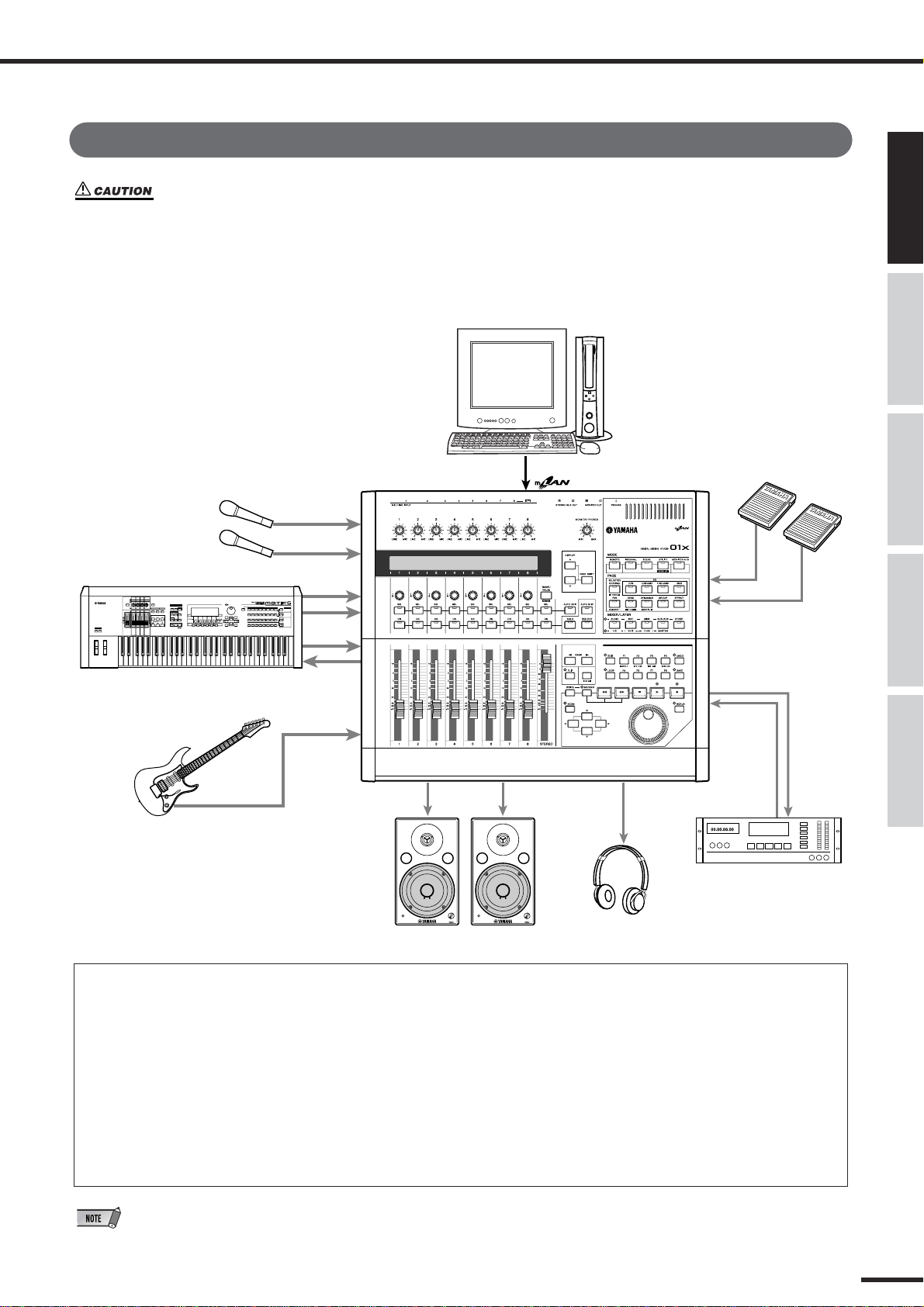
Connections
• Before connecting the 01X to other electronic components, turn off the power to all the components.
Before turning the power on or off to all components, set all volume levels to minimum (0). Otherwise,
electrical shock or damage to the components may occur.
The following diagram shows a typical example of connections to the 01X. Connect your microphones, instruments, and external devices as shown in this diagram.
IEEE 1394-equipped Computer
Foot Switch FC5 or FC4
Microphone
MIC/LINE INPUT
1
Connections
Before UsingBasics SectionAppendix Getting StartedReference
Synthesizer/Tone generator
Electric guitar/Electric bass
2
3 ~ 8
MIDI IN
MIDI OUT
MIC/LINE INPUT
8 (HI-Z)
MONITOR OUT
01X mLAN MUSIC PRODUCTION STUDIO
Copyright(c) Yamaha
Monitor system
PHONES
Headphones
FOOT
SWITCH
1
2
DIGITAL
STEREO OUT
DIGITAL
STEREO IN
DAT recorder, MD recorder, etc.
● Wordclock
Digital audio equipment must be synchronized when digital audio signals are transferred from one device to another. Even
if both devices use identical sampling rates, digital signals may not transfer correctly, or audible noise or unwanted clicks
may occur if the digital audio processing circuits inside each digital audio device are not synchronized with each other.
Wordclocks are signals that enable digital audio processing circuits to synchronize with each other. In a typical digital
audio system, one device operates as the wordclock master, transmitting wordclock signals, and the other devices operate
as wordclock slaves, synchronizing to the wordclock master. If you are digitally connecting the 01X to other equipment, you
must decide which device to use as the wordclock master and which devices to use as slaves, then set up all the devices
accordingly. The 01x can be used as the wordclock master running at either 44.1 kHz, 48kHz, 88.2 kHz (Macintosh only),
or 96 kHz, or slaved to an external wordclock source. When mLAN is used, the 01X’s mLAN Auto Wordclock must be set to
ENABLE (page 92).
•For information on installing the mLAN driver and connecting the 01X to your computer via mLAN as well as information
on necessary system requirements, refer to the separate Installation Guide.
01X Owner’s Manual
23
Page 24
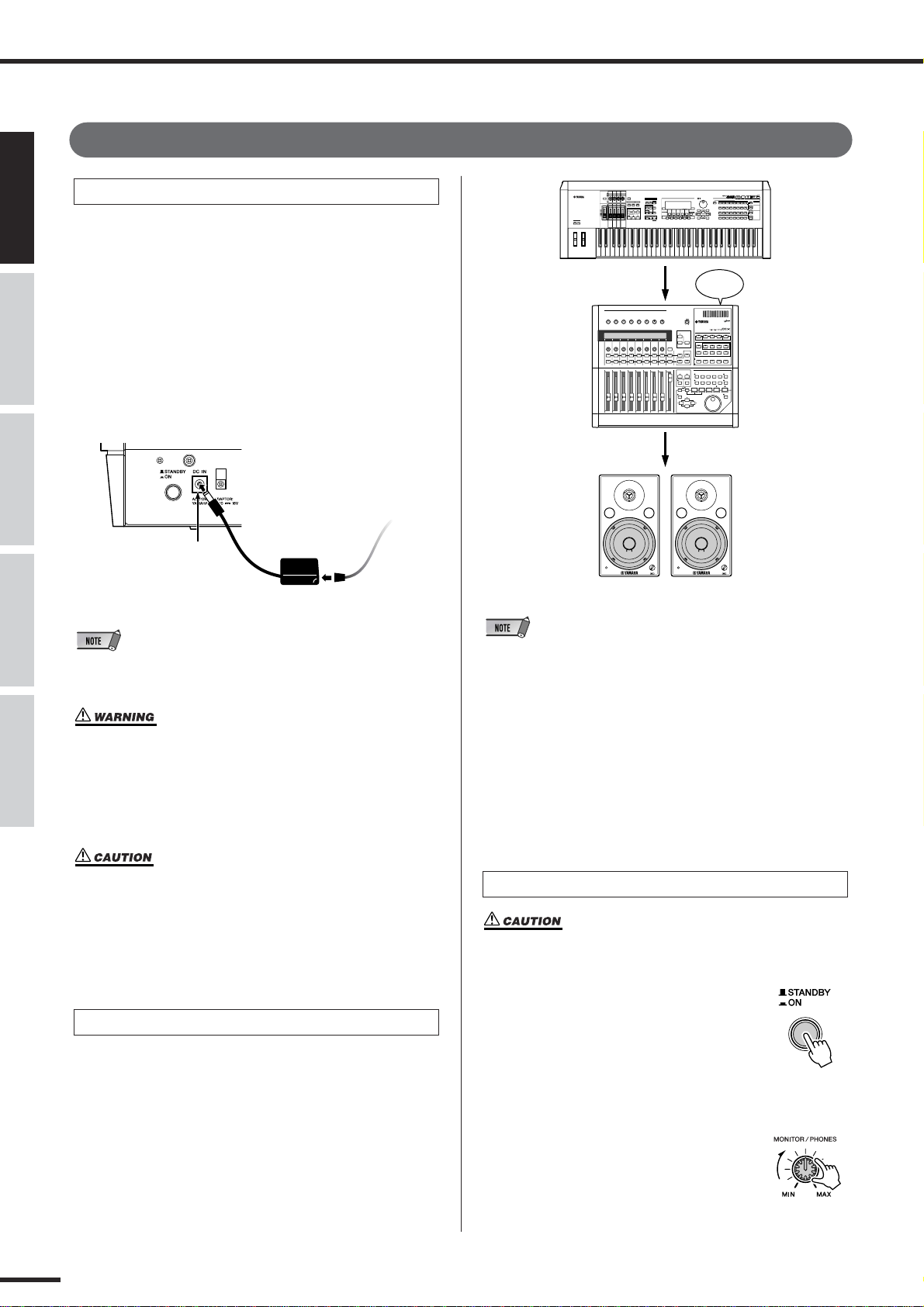
Setting Up
POWER
ON!!
Before Using Basics Section AppendixGetting Started Reference
Setting Up
Power Supply
Make sure that the 01X’s [STANDBY/ON] switch is set to
the STANDBY (off) position.
q Connect one end of the AC cable to the PA-300.
w Connect the PA-300’s DC plug to the 01X’s DC IN ter-
minal on the rear panel.
e Connect the other end (normal AC plug) to the nearest
electrical outlet.
Rear Panel
To electrical
outlet
e
w DC IN
PA-300
AC cable
q
• When unplugging the AC Adaptor, disconnect it in reverse order from
that above.
• Do not attempt to use an AC adaptor other than the Yamaha PA300 or an equivalent recommended by Yamaha. The use of an
incompatible adaptor may cause irreparable damage to the 01X,
and may even pose a serious shock hazard! ALWAYS UNPLUG
THE AC ADAPTOR FROM THE AC POWER OUTLET WHEN THE
01X IS NOT IN USE.
• Even when the switch is in the “STANDBY” position, electricity
is still flowing to the instrument at a minimum level. When not
using the 01X for an extended period of time, be sure to unplug
the AC power adaptor from the wall AC outlet.
Power-on Procedure
Once you’ve made all the necessary connections (page 23)
between your 01X and any other devices, make sure that
all volume settings are turned down all the way to zero,
then turn on the every device in your setup in the order of
MIDI masters (senders), MIDI slaves (receivers), then
audio equipment (mixers, amplifiers, speakers, etc.). This
ensures smooth signal flow from the first device to the last
(first MIDI, then audio).
• Before beginning installation of mLAN Driver for Windows, switch off
the power to the 01X (see the separate Installation Guide).
• When powering down the setup, first turn down the volume for each
audio device, then switch off each device in the reverse order (audio
devices first, then MIDI).
• Be sure to restart your DAW after restarting the 01X (turning the
power off and on again) or switching the DAW in the Remote Select
menu (page 87). (This applies when using SQ01, Cubase/Nuendo or
Digital Performer.)
Turning on the 01X
• Before you switch your 01X on or off, turn down the volume of
any connected audio equipment.
q Press the [STANDBY/ON] switch.
A splash screen is displayed. The
Internal mode (Home) screen
appears next.
w Raise the sound system volume to a
reasonable level.
e Turn the 01X’s MONITOR/
PHONES knob clockwise to set an
appropriate volume level.
01X Owner’s Manual
24
Page 25
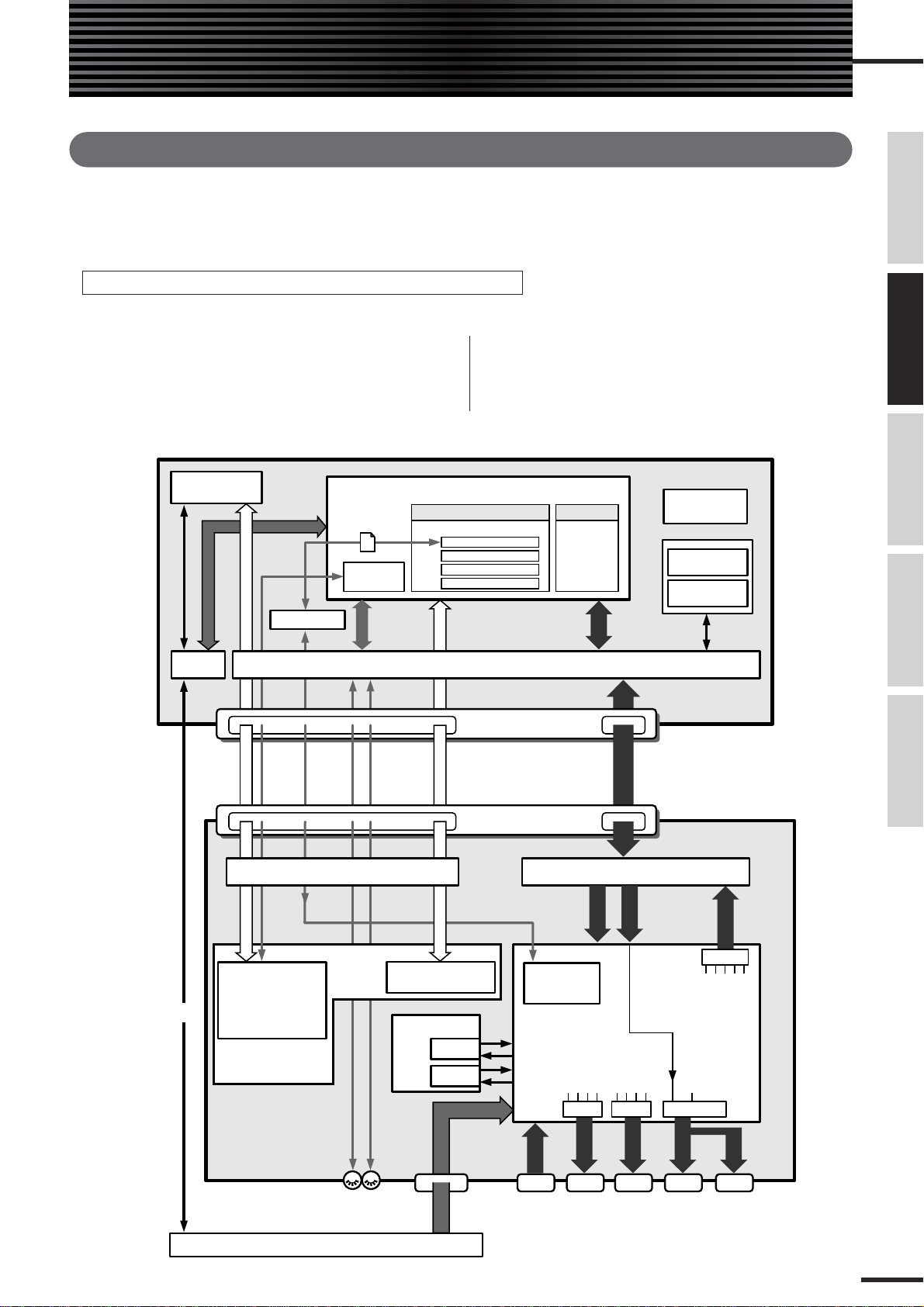
Basics Section
Overview of the 01X
This section gives you an overview of the 01X’s features. The following diagram shows the various component
sections or “blocks” of the 01X: mixer, effects and remote control. It also indicates the mLAN interface capabilities, both audio and MIDI.
Signal flow between the 01X and the DAW on the computer
● When using a DAW other than SQ01 V2
*1 On Macintosh, MIDI data is transfered between the drivers and the
applications by using OMS (Open Music System).
*2 Windows only.
*3 Figures in parentheses indicate the number of available channels when
the wordclock is set to 88.2kHz or 96kHz.
Computer
*4 You can monitor the output directly (monitor cascade) through the con-
nected speaker system/headphones (according to the [MONITOR A/B]
setting), if the stereo master output of the DAW is set to the last two
available channels (the last two numbered channels specified with
mLAN Auto Connector; refer to the separate Installation Guide).
Before UsingBasics SectionAppendix Getting StartedReference
01X
Multi Part Editor
for MOTIF-RACK
USB MIDI
Driver
Port
USB
*2
*1
MIDI
StudioManager
Port4Port
Remote Control
5
mLAN MIDI/MIDI conversion
Remote Control of
Multi Part Editor
or
Program Change/
Scene Selection
(Port 5)
Remote Control
File exchange
Program
Change
MIDI
Port
3
2
DAW (Digital Audio Workstation)
Software Effect
01X Channel Module
Pitch Fix
Vocal Rack
Final Master
mLAN Driver (MIDI & Audio)
mLAN
MIDI IN/OUT
IEEE 1394 Connectors
Port
Remote Control
1
mLAN
MIDI IN/OUT
Remote Control
of DAW (Port 1)
Effects
Effect 1
Effect 2
AUDIO
(Fire Wire, i.Link)
mLAN Connectors 1/2
Commercially
Audio IN/OUT
Audio IN/OUT
Audio IN/OUT
mLAN IN
1 - 16
(1 - 8)
Transfer with
Studio Manager
(Port 4)
Mixer
STI 1
AUX 3
STI 2
AUX 4
Plug-inPlug-in
available
Software
Synthesizer
AUDIO
mLAN
mLAN
mLAN
mLAN Audio/Audio conversion
AUDIO
RECBUS
AUX 1/2
AUX 3/4
STEREO
Select
STEREO
Select
(for PDF Manual)
mLAN AUDIO
*4
mLAN
AUDIO
STEREO IN
17,18 (9,10)
Input
Monitor
RECBUS
AUX 1/2
AUX 3/4
Mix Balance
Acrobat Reader
mLAN
Auto Connector
mLAN
Driver Setup
Select
STEREO
RECBUS
STEREO
*3 *3
mLAN OUT
1 - 24
AUDIO
(1 - 16)
AUX 1/2
AUX 3/4
Direct OUT 1 - 24
MIDI B
IN/OUT
MOTIF-RACK
MIDI A
IN/OUT
MIC/LINE
INPUT
1 - 8 (A/D IN)
AUDIO
DIGITAL
STEREO
IN
AUDIO
DIGITAL
STEREO
OUT
AUDIO
STEREO/
AUX OUT
AUDIO
MONITOR
OUT
AUDIO
PHONES
01X Owner’s Manual
25
Page 26
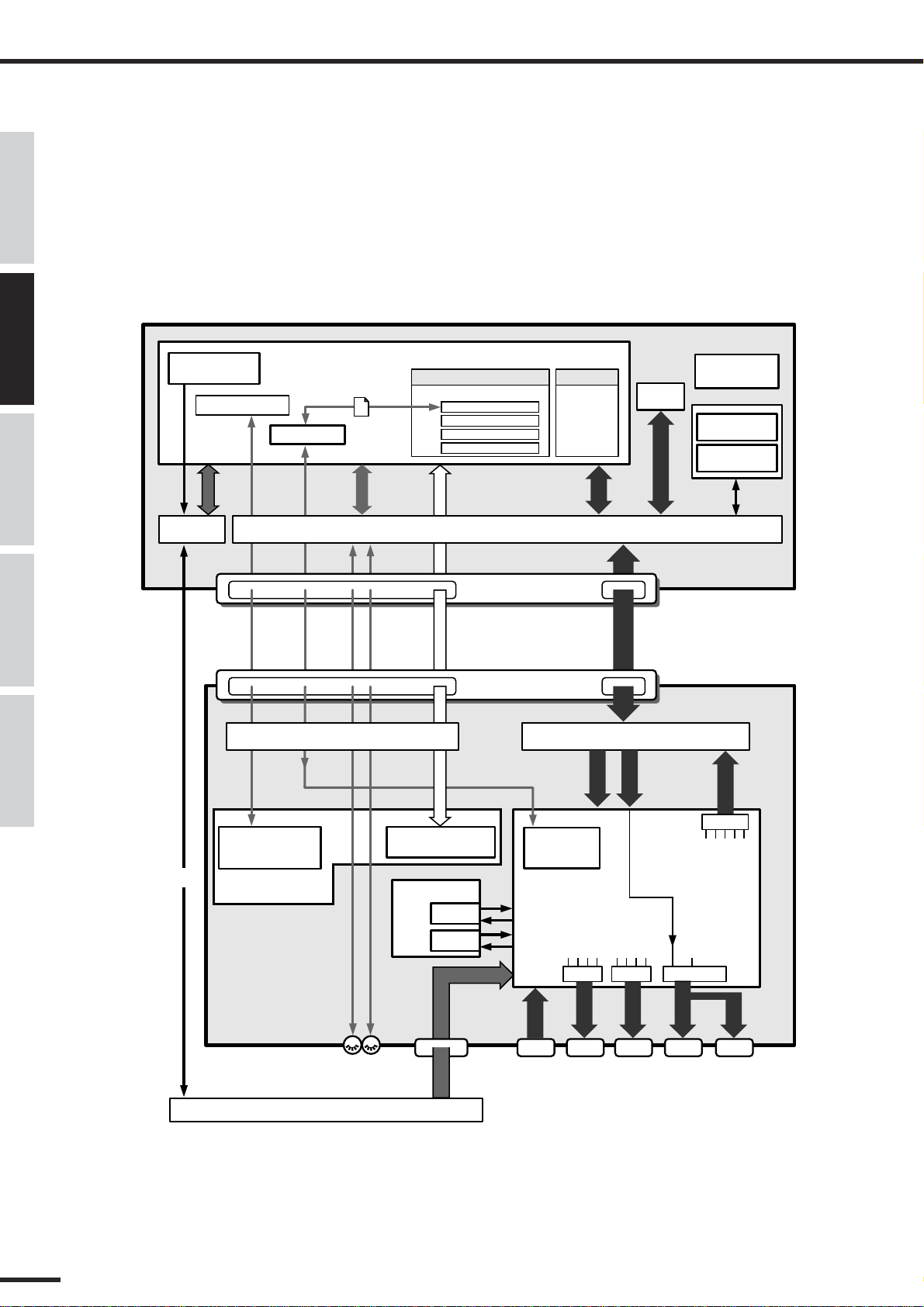
Before Using Basics Section AppendixGetting Started Reference
Overview of the 01X
● When using the included SQ01 V2
Computer
01X
Multi Part Editor
for MOTIF-RACK
Program Change
*1
MIDI
USB MIDI
Driver
USB
*2
StudioManager
Port
Program Change/
Port4Port
5
mLAN MIDI/MIDI conversion
Scene Selection
(Port 5)
Remote Control
File exchange
MIDI
Port
3
2
SQ01 V2
Software Effect
01X Channel Module
Pitch Fix
Vocal Rack
Final Master
mLAN Driver (MIDI & Audio)
mLAN
MIDI IN/OUT
IEEE 1394 Connectors
Port
Remote Control
1
mLAN
MIDI IN/OUT
Remote Control
of DAW (Port 1)
Effects
Effect 1
Effect 2
AUDIO
Plug-inPlug-in
Commercially
available
Software
Synthesizer
mLAN
Audio IN/OUT
(Fire Wire, i.Link)
mLAN Connectors 1/2
mLAN
mLAN
Audio IN/OUT
Audio IN/OUT
mLAN Audio/Audio conversion
mLAN IN
1 - 16
(1 - 8)
Transfer with
Studio Manager
(Port 4)
Mixer
STI 1
AUX 3
STI 2
AUX 4
STEREO
Select
AUDIO
AUDIO
RECBUS
AUX 1/2
AUX 3/4
TWE *2
mLAN AUDIO
*4
*3 *3 *3
mLAN
AUDIO
STEREO IN
17,18 (9,10)
Input
Monitor
STEREO
RECBUS
AUX 1/2
AUX 3/4
Select
Acrobat Reader
(for PDF Manual)
Auto Connector
Driver Setup
AUDIO (WDM)
Select
STEREO
STEREO
Mix Balance
mLAN
mLAN
mLAN OUT
1 - 24
AUDIO
(1 - 16)
AUX 1/2
AUX 3/4
RECBUS
Direct OUT 1 - 24
MIDI B
IN/OUT
MOTIF-RACK
01X Owner’s Manual
26
MIDI A
IN/OUT
MIC/LINE
INPUT
1 - 8 (A/D IN)
AUDIO
DIGITAL
STEREO
IN
AUDIO
DIGITAL
STEREO
OUT
AUDIO
STEREO/
AUX OUT
AUDIO
MONITOR
OUT
AUDIO
PHONES
Page 27

Overview of the 01X
INPUT 1(...8)
ST IN 1(...2)
+48V
MIC/LINE INPUT
AD
INPUT
1/2
PHANTOM
LINE MIC
INPUT
3-8
Hi-z
INPUT 8 ONLY
LINE MIC
AD
DIGITAL STEREO IN
2
COAXIAL
SRC
EFFECT 1
AUX3
INSERT SEND
24
*1
SELECT
EFFECT
EFFECT 2
AUX4
INSERT SEND
24
*1
SELECT
EFFECT
INPUT SELECT (INPUT PATCH)
2 2
22
(to BUS CASCADE)
AD
1/2
AD
3-8
DINL/R
FX1
FX2
METER
*3
(FX)
METER
*3
(FX)
EFFECT2 is available in
48kHz/44.1kHz mode only.
*1 Wordclock 96kHz/88.2kHz : 16
*3 Studio Manager only
Mixer
● Symbol Indications
.......... Amplifier stage
.......... Value change via knob
.......... Value change via fader
.......... On/off switch, button
.......... Phase
.......... Connected
.......... Unconnected
.......... AD (Analog/Digital) converter
AD
.......... DA (Digital/Analog) converter
DA
SRC
.......... Sampling rate converter
Getting Started (page 61)
Input patch Reference (page 88)
The Input Patch section allows assignment of input signals
to input channels 1 through 8 and stereo input channels
(STI) 1/2. The following types of input signals can be
selected.
•MIC/LINE INPUT 1-8
• DIGITAL STEREO IN
• EFFECT(FX)1/2
(Return signals from internal effects 1/2; ST IN only)
Before UsingBasics SectionAppendix Getting StartedReference
* Switches or faders connected with dotted line mean the set-
ting/value for one is linked to the other.
•For information on the entire signal flow of the 01X, refer to the Block
Diagram (at the end of this owner’s manual).
01X Owner’s Manual
27
Page 28

Overview of the 01X
Before Using Basics Section AppendixGetting Started Reference
Input channel
● Input channels 1 through 8
These are monaural input channels used mainly for input
of microphones or line-level instruments. The signals that
are input to input channels 1 through 8 pass through an
attenuator, phase switch, 4-band EQ, and dynamics processor, and are sent to the stereo bus, AUX buses 1 through 4
and Rec bus. Input channels 1 through 8 also have a direct
output (DIRECT OUT), which allows them to be sent
directly from mLAN outputs.
Input channels 9 through 24 (mL1 through mL16)
●
These are input channels for the signal from mLAN IN.
Each of these channels is structured the same as the input
channels. When the 01X is set to 88.2kHz (Macintosh
only)/96kHz operation, mLAN input (from computer to
the 01X) is limited to 8 channels (9-16: mL1-mL8).
•Faders and most parameters of adjacent odd-even channels are
linked for stereo operation (page 102).
● 01X Channel Module
The included “01X Channel Module” is a special plug-in
effect that reproduces the Dynamics and four-band EQ
processing of these input channels using the processing power of your computer (refer to the separate Installation Guide). You can use the 01X Channel Module on
your DAW independently from the 01X. For example
when recording, you can apply Dynamics and EQ to the
01X’s monitor sound only and record dry to the DAW,
then play back the track, processing it with the 01X
Channel Module as needed — all without the 01X.
(Refer to the “DIRECT OUT POSITION” on page 91
and the 01X Channel Module PDF manual.)
INPUT 1(...8)
ATT
INPUT SELECT (INPUT PATCH)
INPUT 9(...24*1) (mL1-mL16*2)
mLAN IN
1-16
mLAN INPUT
IEEE 1394
ATT
*2
INSERT
4BAND EQ
Mono in X 8
INSERT
4BAND EQ
Mono in X 16
(96kHz/88.2kHz: X 8)
*2
16
2
DY-
NAMICS
*3
METER
(Gain Reduction)
DY-
NAMICS
*3
METER
(Gain Reduction)
mLAN IN
mLAN STEREO IN
(MONITOR IN)
(to MONITOR CASCADE)
RECBUS (BUS) R
RECBUS (BUS) L
STEREO (STEREO BUS) L
AUX 2
AUX 3 (FX1)
AUX 4 (FX2)
STEREO (STEREO BUS) R
AUX 1
METER
LEVEL
ON
ON
LEVEL
PAN
PRE/POST ON
PAN
PRE/POST ON
AUX
DIRECT
OUT1(...8)
METER
AUX
DIRECT
*1
OUT9(...24
)
*1 Wordclock 96kHz/88.2kHz : 16
*2 Wordclock 96kHz/88.2kHz : 8
*3 Studio Manager only
01X Owner’s Manual
28
Page 29
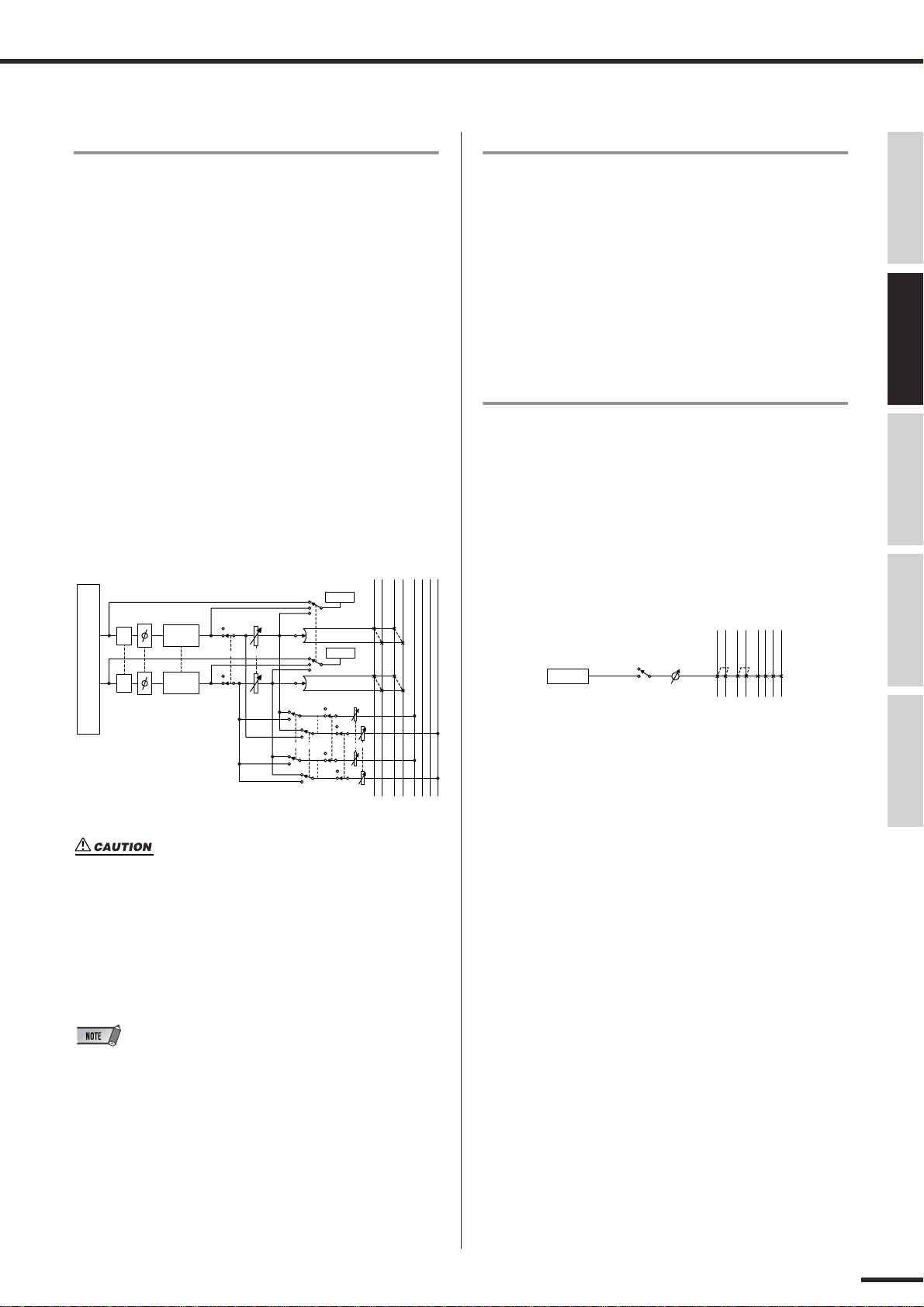
Overview of the 01X
RECBUS (BUS) L
RECBUS (BUS) R
STEREO (STEREO BUS) L
STEREO (STEREO BUS) R
AUX 1
AUX 2
AUX 3 (FX1)
AUX 4 (FX2)
OSCILLATOR
LEVEL
ON
Stereo input channels 1/2
These are stereo input channels used mainly for inputting
the return signal from internal effects 1/2. However, the
input signal assignment can be changed in the input patch
section, allowing these to be used as additional input channels.
The level (return level) of the stereo input channels can be
controlled by using the channel faders 7 (for Effect 1) and
8 (for Effect 2) when [MASTER] layer in the MIXER/
LAYER is seleced in Internal mode.
● Differences from input channels
• Stereo
• No dynamics processor
• No direct output
RECBUS (BUS) L
STEREO (STEREO BUS) L
AUX 2
STEREO (STEREO BUS) R
RECBUS (BUS) R
ST IN 1(...2)
METER
AUX 1
AUX 3 (FX1)
AUX 4 (FX2)
Digital cascade connection
The input signal from the rear panel DIGITAL STEREO
IN connector can be cascade-connected directly to the stereo bus, instead of being routed through the input patch
section and patched to an input channel. This is convenient
when you want to link an external digital mixer or similar
device with the mixer section of the 01X. (Refer to the
“Digital In Stereo Bus Cascade” on page 93.)
Oscillator
The 01X contains an oscillator that allows you to select
either sine wave (100Hz, 1kHz, 10kHz) or white noise.
The oscillator signal can be sent to rec bus, AUX buses 1
through 4, or the stereo bus. (Refer to the “Oscillator” on
page 93.)
Before UsingBasics SectionAppendix Getting StartedReference
LEVEL
PAN
PAN
METER
ON
AUXPRE/POST
ATT
ATT
INPUT SELECT (INPUT PATCH)
4BAND EQ
4BAND EQ
Stereo in X 2
(96kHz/88.2kHz: X 1)
ON
• When using an internal effect via the Aux Send, do NOT turn up
the send level to the corresponding AUX bus for the channel to
which the effect return signal is routed. Doing so will result in
loud feedback, and may damage your equipment. For example,
when the 01X is in the default condition, AUX 3 is routed to the
input of internal effect 1, and the L/R signals of the ST IN channel 1 are routed to the output. If you turn up the send level of ST
IN channel 1 to AUX 3, a feedback loop is created.
• Since stereo input channels 1/2 are stereo, adjacent odd-numbered/
even-numbered signals will be assigned to them when MIC/LINE
inputs are selected as the input signals. Also, if DIGITAL STEREO IN
is selected, both L and R signals will be assigned.
01X Owner’s Manual
29
Page 30

Overview of the 01X
AUX1(...4)
AUX 1
AUX 2
AUX 3 (FX1)
AUX 4 (FX2)
LEVEL
METER
-10dBV
L
R
STEREO/AUX OUT
DA
DA
DIGITAL STEREO OUT
COAXIAL
2
mLAN OUT
2
RECBUS
24
*1
DIRECT OUT1-24
*1
24
*1
IEEE 1394
DITHER
STEREO
2
2
RECBUS
2
AUX1/2
2
AUX3/4
STEREO
2
2
RECBUS
2
AUX1/2
2
AUX3/4
SELECT
(OUT PATCH)
2
AUX1/2
2
AUX3/4
STEREO
2
SELECT
(OUT PATCH)
SELECT
(OUT PATCH)
*1 Wordclock 96kHz/88.2kHz : 16
Before Using Basics Section AppendixGetting Started Reference
Output channel
● Stereo output channel
This is a stereo output channel that processes the signals
sent from each channel to the stereo bus. Stereo faders contorl the level of these outputs. It provides a 4-band EQ and
dynamics processor identical to those provided on the
input channels. The output signal of the stereo output channel is sent via the output patch section to the various output
jacks, and is also simultaneously output to the MONITOR
OUT jacks and PHONES jack.
METER
STEREO (STEREO BUS) L
AUX 2
AUX 3 (FX1)
AUX 4 (FX2)
STEREO (STEREO BUS) R
AUX 1
ATT
4BAND EQ
ATT
4BAND EQ
DY-
NAMICS
DY-
NAMICS
METER
(Gain Reduction)
● Rec bus output channel
This is a stereo output channel that processes the signals
sent from each channel to the rec bus. It provides a fourband EQ and dynamics processor identical to those provided on the input channels. The output signal of the rec
bus channel is sent via the master level/output patch section to the various output jacks.
INSERT
ON
BAL
LEVEL
*3
*3 Studio Manager only
STEREO L
METER
STEREO R
● AUX buses 1 through 4
The signals sent from each channel to AUX buses 1–6 pass
through a master level, and are sent to the output patch section.
The master level of AUX buses 1 through 4 can be controlled by using the channel faders 3 through 6 when
[MASTER] layer in the MIXER/LAYER is seleced in
Internal mode.
Getting Started (page 62)
Output patch Reference (page 90)
Output Patch is the section where output signals are
assigned to mLAN channels 1/2 through 23/24, DIGITAL
STEREO OUT jack, and STEREO/AUX OUT jack. The
following output signals can be selected.
• Stereo bus (The output signal of the stereo bus routed
through the stereo output channel.)
• Rec bus
•AUX bus 1/2
•AUX bus 3/4
The master level of the rec bus can be controlled by using
the channel 1 fader when [MASTER] layer in the MIXER/
LAYER is seleced in Internal mode.
RECBUS (BUS) R
RECBUS (BUS) L
STEREO (STEREO BUS) L
AUX 2
AUX 3 (FX1)
AUX 4 (FX2)
STEREO (STEREO BUS) R
AUX 1
30
01X Owner’s Manual
DY-
NAMICS
DY-
NAMICS
*3
METER
(Gain Reduction)
INSERT
*3 Studio Manager only
LEVEL
METER
RECBUS L
METER
RECBUS R
• In general, these output signals can be assigned to any output jack or
output channel. For the STEREO OUT jacks and DIGITAL STEREO
OUT jacks, two adjacent odd-numbered/even-numbered signals will
always be assigned.
• The direct out setting for a specific channel is cancelled if the corresponding output channel is assigned to stereo bus, rec bus or AUX
buses (page 90).
Page 31

Overview of the 01X
EFFECT 1
AUX3
INSERT SEND
24
*1
SELECT
EFFECT
EFFECT 2
AUX4
INSERT SEND
24
*1
SELECT
EFFECT
INPUT SELECT (INPUT PATCH)
2 2
22
EFFECT2 is available in
48kHz/44.1kHz mode only.
*1 Wordclock 96kHz/88.2kHz : 16
*3 Studio Manager only
FX1
FX2
METER
*3
(FX)
METER
*3
(FX)
Monitor output/headphone output
For monitoring purposes, the 01X provides MONITOR
OUT jacks and a PHONES jack. The MONITOR OUT
jacks and PHONES jack always output the same signal,
and is linked to the level adjustment. You can monitor the
output directly (monitor cascade) through the connected
speaker system/headphones (according to the [MONITOR
A/B] setting), if the stereo master output of the DAW is set
to the last two available channels (the last two numbered
channels specified with mLAN Auto Connector; refer to
the separate Installation Guide). (Refer to “Monitor” on
page 96.)
mLAN STEREO IN
(MONITOR IN)
mLAN STEREO IN
(MONITOR IN)
(MONITOR CASCADE)
STEREO L
STEREO R
L
R
BAL
MONITOR
A/B
(Mix Balance)
DA
DA
Min Max
MONITOR/
PHONES Knob
PHONES
MONITOR OUT
L
-10dBV
R
Internal effects 1/2
The two built-in effect units deliver a wide variety of
effects including spatial-type effects such as reverb and
delay, modulation type effects such as chorus and flanger,
and guitar-type effects such as distortion and amp simulation. These effects can be used via Aux send (the level corresponds to the master level of the stereo input channels),
or inserted into a desired channel.
Before UsingBasics SectionAppendix Getting StartedReference
• If 88.2kHz/96kHz operation is enabled, only one internal effect block
is available (Effect 1/Aux 3).
•For details about each Effect Type, refer to page 125; for details
about each Effect Parameter, refer to page 126.
•For an application example showing how to use the effects, see page
57.
01X Owner’s Manual
31
Page 32

Overview of the 01X
01X
01X
Use the faders to
record level changes
in the DAW channels.
During song playback, the faders on the
01X move in response
to the recorded level
changes.
Computer (DAW)
Computer (DAW)
Before Using Basics Section AppendixGetting Started Reference
Remote Control
With mLAN MIDI transfer, the 01X can be used to conrtol
DAW (digital audio workstation) software, such as Cubase
SX and Logic, as well as the Multi Part Editor for Yamaha
MOTIF ES or MOTIF-RACK program (contained on the
included CD-ROM). This powerful feature lets you control
software programs by using knobs, faders and buttons on
the panel of the 01X, rather than your computer’s mouse
and keyboard.
● Because of the bi-directional data flow between the
01X and the computer, the changes you make to levels
and parameter values are immediately mirrored in the
LCD of the 01X — giving you intuitive and instant
editing in real time, without having to check the computer display.
Drums- Drums- SteelG SteelG CleanG CleanG DistGt DistGt
PAN PAN PAN PAN PAN PAN PAN PAN
● Since control of the DAW mixer channels and 01X
channels is simultaneous and bi-directional, you can
record level changes in the song data and have them
reflected automatically in the 01X faders, providing
full mixer automation.
Remote
operation
Computer (DAW)
01X
Display information
(parameter names/values)
•For details on the functions in the Remote mode, see the Remote
Function List (page 104).
• Depending on your particular DAW, not all control features may be
implemented, and some buttons may be assigned different functions.
Refer to the owner’s manual of your particular DAW for specific
instructions and setups.
• Remote control is only possible when the version of your particular
DAW application and operating system conforms to the system
requirements. For details, refer to the separate Installation Guide.
•For information on the necessary setup for Remote Control, refer to
page 66 (Cubase SX/SL) or the “Demo Song Playback” in the separate Installation Guide (other than Cubase SX/SL).
01X Owner’s Manual
32
Page 33

mLAN Interface
The mLAN interface of the 01X also lets you connect
MIDI or audio devices that do not have mLAN connectors
or capability. The following conversion is possible:
• mLAN MIDI signal to/from MIDI signal (2 ports)
(mLAN MIDI IN/OUT Port 2/3 of mLAN connectors
to/from MIDI IN/OUT A/B jack)
• mLAN audio signal to/from analog audio signal
• mLAN audio signal to/from digital audio signal
• Analog audio signal to/from digital audio signal
Overview of the 01X
Before UsingBasics SectionAppendix Getting StartedReference
01X Owner’s Manual
33
Page 34

Application examples
Before Using Basics Section AppendixGetting Started Reference
Application examples
The 01X is one of the most versatile recording mixers available. Its all-in-one, fully digital operation makes it ideal for songwriters, producers, project studios, home recording, and virtually all post-production applications. Here are some of the ways
you can set up and use the 01X in your own system.
1) Recording mixer and monitor mixer
In this application example, vocals and instruments can be
recorded to computer while monitoring playback of MIDI
tone generators with the 01X.
Computer
01X
Mic
HDR
Gt
(Wave)
EQ, Dynamics
Synth
Audio Mixer
Synth/TG
Synth
• Soft EQ
• Soft Effect
Effect
Monitor Out
Recording mixer features
Naturally, the 01X gives you simultaneous eight-channel
input with full mixing control—level adjustment, Dynamics, and four-band EQ. Using the Channel Module software on your computer gives you onscreen display and
control of level, Dynamics, and the four-band EQ.
This application also takes advantage of the flexible routing options, letting you set up a separate stereo bus and
recording bus. Moreover, the individual vocals and instruments are recorded directly to computer as 24-bit digital
audio data—at up to 96kHz sampling rate, if desired.*
* When the 01X is set to 88.2kHz/96kHz operation, mLAN trans-
mission (from the computer) is limited to eight channels and only
one internal effect block can be used.
Here, the sequencer data drives the MIDI instruments
which come in stereo via two input channels and are processed with Dynamics, EQ and effects as needed. The signal is then routed to the MONITOR OUT bus for
monitoring. Vocals, guitar and keyboard are input to the
other channels and are sent (after Dynamics and EQ processing) directly to the computer.
This setup lets you record instruments in real time to existing sequence data, while hearing the previously recorded
MIDI tracks. Any audio tracks and plug-in synthesizers,
etc. can also be monitored.
Remote control features
Control your computer’s audio/MIDI sequencer from the
01X while tracking, alternately switching between
INTERNAL and REMOTE as needed. The 01X also gives
you control over the audio mixer in the sequencer (including the plug-in instruments), as well as detailed parameter
control over the plug-in effects.
Monitor mixer features
Another huge benefit of this setup is that the mixer inputs
recorded to the computer can be monitored directly from
the 01X—complete with all Dynamics, EQ and effect processing. You can also monitor the audio tracks on the computer with 01X effect processing as well, via the input
channels or the DIGITAL IN terminal.
01X Owner’s Manual
34
Page 35

Application examples
EQ, Dynamics
01X
Computer
HDR
(Wave)
Synth
Synth/TG
Mic
Gt
Synth
Effect
Studio Manager
EQ, Dynamics
Monitor Out
Audio Mixer
EQ, Dynamics
EQ, Dynamics
2) Digital mixer function
Here, the 01X functions simultaneously as a front-end/
audio interface for a computer system as well as a fully
digital mixer for your sequencer audio tracks.
Computer
01X
Mic
With the mLAN connection, this system allows you to
route up to sixteen independent audio channels (plus the
two-channel stereo master) from the computer to the input
channels of the 01X, and have the eight rear-panel inputs
available for your vocals and other instruments. Naturally,
all Dynamics, EQ and effect processing are available for
this 24-channel setup. Finally, you can also use this same
configuration for mixdown—returning the entire sound
with processing to the computer for mastering.
(Wave)
HDR
EQ, Dynamics
Synth/Instrument
Gt
EQ, Dynamics
Synth
Audio Mixer
Effect
Monitor Out
3) Recording mixer, monitor mixer —
with use of 01X Channel Module
software and Studio Manager
This advanced hardware/software hybrid system combines
the conveniences of computer-based mixing/processing
with the intuitive control surface and digital processing of
the 01X.
In this application, the 01X Channel Module plug-in and
the Studio Manager software (both included with the 01X)
are used to link mixing and processing operations between
the 01X and your computer. The result is a transparent,
exceptionally easy-to-use hardware/software combination.
The panel controls on the 01X and the controls of Studio
Manager on the computer are linked directly—adjusting a
parameter on one changes that of the other. The Studio
Manager has conventional channel strips that you can control from the 01X. It also has special windows for the
Dynamics processing, EQ, and effects. The EQ window,
for example, features a frequency response graph that
changes as you make the settings—very intuitive and very
easy.
Before UsingBasics SectionAppendix Getting StartedReference
With this configuration, you can use the channel processing on the 01X to hear the intended final sound, but record
dry to computer.
The 01X Channel Module plug-in can be used afterwards
to actually process the recorded sound as you wish. Moreover, you can copy settings from Studio Manager to the
01X Channel Module and adjust/tweak the mix using the
Channel Module plug-in. Settings you’ve made or
changed in the Channel Module can also be transferred
back to Studio Manager.
01X Owner’s Manual
35
Page 36

Memory (Library) Structure
Before Using Basics Section AppendixGetting Started Reference
Memory (Library) Structure
The 01X features several libraries (internal memory) that enable you to store Scene, Input Patch, Output Patch
and other data. You can also quickly recall this data from the libraries to restore previous parameter values. Furthermore, the Backup function lets you save your data including the Utility settings. The 01X offers the following
libraries:
■ Library
Scene : 100 page 85
Default
settings
00
01
. . .
99
Input Patch : 33 page 89
Default
settings
00
01
. . .
32
Output Patch : 33 page 91
Default
settings
00
01
. . .
32
EQ : 200 page 99
01 . . . 40 41
. . .
200
Dynamics : 128 page 100
01 . . . 40 41
. . .
128
Effect 1/2 : 128 page 103
(Settings that apply to both 1 and 2 effect units)
01 . . . 43 44
. . .
128
Channel : 129 page 103
Default settings
(-∞dB)
Default settings
(Nominal level : 0dB)
0100
02
. . .
■ System Backup
Backup : 1 page 86
Utility
Monitor settings
The current Scene, Channel,
+
EQ, Dynamics, Effect,
Input Patch, Output Patch
mLAN
Settings are compatible.
(See the Studio Manager
PDF manual.)
Studio Manager
Settings are compatible.
(See the 01X Channel
Module PDF manual.)
128
• The 01X Utility and Monitor settings are lost when
the power is turned off, unless System Backup is
performed. In order to ensure the settings here
are effective the next time you turn the 01X on,
perform System Backup by holding [SHIFT] and
pressing [UTILITY] (page 86).
Preset
Destination for Store
operation
*For details about each Preset
Library parameter, refer to the
Appendix section.
01X Owner’s Manual
36
01X Channel Module
Page 37

Basic Operations
Basic Operations
In this section, you’ll learn about the structure of the modes of the 01X, its panel display indications and its fundamental operations.
Modes
[REMOTE] button [INTERNAL] button [SCENE] button [UTILITY] button [MONITOR A/B] button
Before UsingBasics SectionAppendix Getting StartedReference
Display
Mode LED Operation/Settings
REMOTE
Mode
INTERNAL
Mode
LIBRARY SCENE ([SCENE] lights) Save (store) each Library data. — [SCENE] ➝ DISPLAY [ ] H 85
GENERAL (SQ01) [REMOTE] lights Remote Control of the computer software (DAW).
LOGIC [REMOTE] lights [REMOTE] 106
CUBASE [REMOTE] lights [REMOTE] 108
SONAR [REMOTE] lights [REMOTE] 110
DIGITAL PERFORMER [REMOTE] lights [REMOTE] 112
Multi Part Editor
(Stand Alone)
HOME [INTERNAL] lights Adjusts the input level for the currently selected chan-
SCENE [SCENE] lights Scene settings (Saving or recalling the mixer/effect
UTILITY [UTILITY] lights Global settings for the entire system/remote control. — [UTILITY] D 86
MONITOR [MONITOR]
PAGE EQ [EQ LOW] lights EQ settings Yes [INTERNAL] ➝ [EQ LOW] F 96
PA N[PAN] lights PAN settings Yes [INTERNAL] ➝ [PAN] 99
DYNAMICS [DYNAMICS] lights DYNAMICS settings Yes [INTERNAL] ➝ [DYNAMICS] 100
SEND [SEND] lights AUX sends settings Yes [INTERNAL] ➝ [SEND] 100
EFFECT [EFFECT] lights EFFECT settings — [INTERNAL] ➝ [EFFECT] G 102
INPUT PATCH ([UTILITY] lights) — [UTILITY] ➝ Channel knob 2 ➝
OUTPUT PATCH ([UTILITY] lights) — [UTILITY] ➝ Channel knob 2 ➝
EQ [EQ LOW] lights Yes
DYNAMICS ([SELECTED
EFFECT ([EFFECT] lights) — [INTERNAL] ➝ [EFFECT] ➝
CHANNEL [SELECTED
GROUP [GROUP] lights GROUP settings Yes [INTERNAL] ➝ [GROUP] 101
[REMOTE] flashes [SHIFT]+[REMOTE]
[SCENE] unlights
[UTILITY] unlights
lights / unlights
[EQ LOW-MID] lights [INTERNAL] ➝ [EQ LOW-MID] 97
[EQ HIGH-MID]
lights
[EQ HIGH] lights [INTERNAL] ➝ [EQ HIGH] 98
[EQ LOW-MID] lights
[EQ HIGH-MID]
lights
[EQ HIGH] lights
CHANNEL] lights
[DYNAMICS] lights)
CHANNEL] flashes
*For specific information on each of the DAW selec-
tions, see page 87.
nels in the MIXER/LAYER. Each channel’s level value/
level meter is displayed. To set the nominal level, press
the appropriate channel knob. To set the default value,
simultaneously hold down the [SHIFT] button and press
the appropriate channel knob.
parameters)
Switches between Monitor A and B. To sets the output
balance between the DAW audio and the audio of the
01X itself, hold down the [MONITOR] button and turn
knob [5] (for A) or [7] (for B).These settings can also be
made in the Monitor display of Utility mode.
Selected
Channel
(SELECTED
CHANNEL
only)
Selecting a mode (example)
— [REMOTE] A 104
(To exit from the Remote mode
for Multi Part Editor, press only
[REMOTE].)
— [INTERNAL] B —
— [SCENE] C 85
—E96
[INTERNAL] ➝ [EQ HIGH-MID] 97
DISPLAY [ / ]
DISPLAY [ / ]
[INTERNAL] ➝
[SELECTED CHANNEL] ➝
[EQ] ➝ DISPLAY [ ]
[INTERNAL] ➝
[SELECTED CHANNEL] ➝
[DYNAMICS] ➝ DISPLAY [ ]
DISPLAY [ / ]
— [SHIFT] +
[SELECTED CHANNEL]
Indications
(page 38)
Related
pages
100
103
103
87
89
91
99
01X Owner’s Manual
37
Page 38

Basic Operations
Mod
Before Using Basics Section AppendixGetting Started Reference
e selection and display indications
(A) Remote Mode
q
Drums- Drums- SteelG SteelG CleanG CleanG DistGt DistGt
L63 R63 R15 R63 L63 R63 L63 R63
y
Drums- Drums- SteelG SteelG CleanG CleanG DistGt DistGt
q
PAN PAN PAN PAN PAN PAN PAN PAN
t
Drums-0Drums-0SteelG0SteelG0CleanG0CleanG0DistGt0DistGt
q
-8.18 -7.73 -8.18 -8.18 -8.18 -8.18 -8.18 -8.18
w
t
PAN
y
L63 R63 R15 R63 L63 R63 L63 R63
FADER
w
-8.18 -7.73 -8.18 -8.18 -8.18 -8.18 -8.18 -8.18
Fader
Fader
(Ex. SQ01 V2)
[NAME/VALUE]
Channel knob
[INTERNAL]
[REMOTE]
[SCENE]
[REMOTE]
(B) Home
LEVEL LEVEL LEVEL LEVEL LEVEL LEVEL LEVEL LEVEL
w
-6.3 -3.05 -3.95 -6.6 -4.85 -3.05 -3.65 -3.6
Fader
e
CH1 CH2 CH3 CH4 CH5 CH6 CH7 CH8
-6.3 -3.05 -3.95 -6.6 -4.85 -3.05 -3.65 -3.6
w
[SCENE]
[INTERNAL]
(C) Scene
SCENE PATCH LIBRARY ASSIGN
SCENE LIBRARY
r
SCENE RECALL SAFE
ENABLE ENABLE ---- ---- ---- ENABLE ---- ----
y
!0
[UTILITY]
[EQ]
[PAN]
[DYNAMICS]
[SEND]
[GROUP]
[UTILITY]
[REMOTE]
(D) Utility
MENU SELECT
r
UTILITY MENU SELECT
REMOTE PATCH W.CLK D.I/O OSC. MIDI PREF. MONI.
u
Channel
knob 1
Channel
knob 2
Channel
knob 8
[UTILITY]
[UTILITY]
[UTILITY]
[UTILITY]
[SCENE]
UTILITY REMOTE AUTOMATION SETUP 3/3
GENERAL LOGIC CUBASE SONAR D.PERF
UTILITY SHIFT+REMOTE FUNCTION [GNRL RMT ] 2/3
UTILITY REMOTE SELECT [GENERAL] 1/3
r
GENERAL LOGIC CUBASE SONAR D.PERF
u
[PAGE SHIFT] + DISPLAY [ / ]
UTILITY INPUT PATCH (IN1-4) 1/8
r
[AD1 ]≥IN1 [AD2 ]≥IN2 [AD3 ]≥IN3 [AD4 ]≥IN4
y
!0
!0
(E) Monitor
r
UTILITY MONITOR A(LED-ON) B(LED-OFF) 1/1
INT> 0:126<DAW INT>126: 0<DAW
[INTERNAL]
DISPLAY [ / ]
io
DISPLAY [ / ]
i
t
y
[EFFECT]
i
01X Owner’s Manual
38
(H) Library
(Ex. Scene Library)
The current (last recalled) Library No.
SCENE LIBRARY SCENE No. [ 01]
02 [Initial Data ] RECALL/STORE CLEAR/PROTECT
Library No. / Name of desired selection
(Select this by using the Channel knobs 1-4)
RECALL : Source for Recall operation
STORE : Destination for Store operation
Channel
knob 1 - 4
u
knob 7/8
● Title Edit display (page 41)
SCENE LIBRARY SCENE No. [ 01]
Channel
02 [Initial Data ] CHAR INSERT EXIT/OK
u
Page 39

Basic Operations
[REMOTE]
[INTERNAL]
[SCENE]
[REMOTE]
(F) Page
(Ex. EQ-LOW)
Multi Channel
e
CH1 CH2 CH3 CH4 CH5 CH6 CH7 CH8
+ 2.1 + 0.4 - 0.4 - 0.4 0.0 + 0.4 + 1.2 0.0
y
Channel knob
CH1 CH2 CH3 CH4 CH5 CH6 CH7 CH8
e
EQL-G EQL-G EQL-G EQL-G EQL-G EQL-G EQL-G EQL-G
t
Fader
LEVEL LEVEL LEVEL LEVEL LEVEL LEVEL LEVEL LEVEL
w
-6.3 -3.05 -3.95 -6.6 -4.85 -3.05 -3.65 -3.6
[NAME/VALUE]
t
EQ LOW GAIN
+ 2.1 + 0.4 - 0.4 - 0.4 0.0 + 0.4 + 1.2 0.0
y
Fader
LEVEL LEVEL LEVEL LEVEL LEVEL LEVEL LEVEL LEVEL
w
-6.3 -3.05 -3.95 -6.6 -4.85 -3.05 -3.65 -3.6
[UTILITY]
(G) Effect
[EQ]
[PAN]
[DYNAMICS]
[SEND]
[GROUP]
[SELECTED
CHANNEL]
Selected Channel
t
EQ LOW SEL<CH1 >
OFF + 0.2 0.11 125 +2.1
y
Channel knob
EQ LOW SEL<CH1 >
t
EQ-ON ATT EQL-Q EQL-F EQL-G
Fader
LEVEL LEVEL LEVEL LEVEL LEVEL LEVEL LEVEL LEVEL
w
-6.3 -3.05 -3.95 -6.6 -4.85 -3.05 -3.65 -3.6
[NAME/VALUE]
t
EQ-ON ATT EQL-Q EQL-F EQL-G SEL<CH1 >
OFF + 0.2 0.11 125 +2.1
y
Fader
LEVEL LEVEL LEVEL LEVEL LEVEL LEVEL LEVEL LEVEL
w
-6.3 -3.05 -3.95 -6.6 -4.85 -3.05 -3.65 -3.6
[EFFECT]
SEL<CH3 >
SEL<CH2 >
Before UsingBasics SectionAppendix Getting StartedReference
e
[SEL]
e
e
DISPLAY [ / ]
[INTERNAL]
[SCENE]
[UTILITY]
EFFECT1 PATCH BYPASS MIX TYPE[REVERB HALL ]
AUX3 -- 100%
t
o
DISPLAY [ / ]
[EFFECT]
q Channel Module Name (Part/Track Name)
w Level (adjusted via Channel faders)
e Channel (channel name) or selected channel (channel
name) assigned to the respective module
CH1-8 : Input Channlel 1-8
mL1-16 : Input Channel 9-24 (mLAN Input Channel 1-16)
BUS:REC Bus
AUX1-4 : AUX Bus 1-4
ST1/2 : Stereo Input Channel 1/2
r Mode
t Parameter/function name
y Settings (selected by turning channel knobs)
u Function or operation (selected by pressing channel knobs)
i Page number
o Currently selected settings
!0 Display name
EFFECT2 PATCH BYPASS MIX TYPE[REVERB HALL ]
AUX4 -- 100%
t
o
DISPLAY [ / ]
•For information about UTILITY OSC. ASSIGN display,
also see page 93.
• Channel name can be edited by using the Studio Manager. (Refer to the PDF manual.)
01X Owner’s Manual
39
Page 40

Basic Operations
Before Using Basics Section AppendixGetting Started Reference
Layer selection/Channel selection
The Input Channels and Output Channels are arranged into layers, as illustrated below. There are four layers altogether.
Input Channel Layer
1 – 8
Input Channel Layer
9 – 16 (mLAN1 – mLAN8)
Input Channel Layer
17 – 24 (mLAN9 – mLAN16)
(48kHz/44.1kHz mode only)
Master Layer
The currently selected layer determines the function of the channel strip, [SEL] buttons, [ON] buttons, and faders. Use the
LAYER buttons to select a layer you wish to edit using the channel strip controls. The following table shows the layers that
you can access using the LAYER buttons, and the parameters you can control using the channel strips on each layer.
LAYER buttons Channel Strips Display Channels can be operated
[1-8] lights 1-8 CH1-CH8 Input Channels 1-8
[9-16] lights 1-8 mL1-mL8 Input Channels 9-16 (mLAN1-mLAN8)
[17-24] lights 1-8 mL9-mL16 Input Channels 17-24 (mLAN9-mLAN16)
1BUS REC Bus Out master
[MASTER] lights
• The STEREO [SEL] button, [ON] button, and STEREO fader always control the Stereo Out signal, regardless of the Layer
settings.
3-6 AUX1-4 AUX Bus 1-4 masters
7/8 STI1/2
Stereo Inputs 1/2
(Stereo Input 2 is 48kHz/44.1kHz mode only)
01X Owner’s Manual
40
Page 41

Basic Operations
SCENE LIBRARY SCENE No. [ 05]
05 [Initial Data ] CHAR INSERT EXIT/OK
● Selected Channel mode
To select a channel on the 01X, press the corresponding
[SEL] button. The channel is selected and the [SEL] button
lamp lights up.
● Stereo Input Channel
For stereo input channels, you can set the left and right
panpots individually. Repearedly pressing the STEREO
[SEL] button toggles between the left and right channels.
• L- : indicates the left channel pan settings of the stereo input channel.
• R- : indicates the right channel pan settings of the
stereo input channel.
PAN
L-L63 L-L63
Entering Characters (Title Edit)
You can freely name the stored Library. The following data
types can be named.
• Scene Library (page 85)
• Input Patch Library (page 89)
• Output Patch Library (page 91)
• EQ Library (page 99)
• Dynamics Library (page 100)
•Effect Library (page 103)
• Channel Library (page 103)
The instructions below apply to naming of any of the
Libraries.
• Library titles are named after the Libraries themselves have been
stored.
• This operation only saves the data of the Library name. Other setting
data is not saved until you actually store the Library (pages 50, 54).
Before UsingBasics SectionAppendix Getting StartedReference
PAN
R-R63 L-L63
q Turn any of the channel knobs [1]- [4] to select the
desired Library number for naming.
w Press any of the channel knobs [1]- [4] to edit the first
position of the name. The first character of the name
flashes.
•To cancel the operation, press channel knob [7] (EXIT).
e Turn any of the channel knobs [2] - [4] to move the cur-
sor to the desired position.
•Keep in mind that turning channel knob [1] exits from the title edit
operation.
01X Owner’s Manual
41
Page 42

Basic Operations
Do you want to initialize backup data? YES NO
Before Using Basics Section AppendixGetting Started Reference
r Enter the letters, numbers, or symbols by turning the
channel knob [5].
SCENE LIBRARY SCENE No. [ 05]
05 [Initial Eata ] CHAR INSERT EXIT/OK
t Turn any of the channel knobs [2] - [4] to move the cur-
sor to the position of the next character.
y Enter the other characters, by repeating steps r - t
above.
Insertion/Deletion of Characters
Channel knob [6] is assigned to Insertion (INSERT)
and Deletion (DELETE). Turn the channel knob [6]
to select the Insertion (INSERT) or Deletion
(DELETE) function.
To insert/delete a particular character, move the
cursor to the desired position (in steps e and t
above) and press channel knob [6]. Note that the
DELETE operation does not delete the character
before the cursor, but the flashing character on the
cursor.
Factory Set (Restore Factory Defaults)
This let you restore the 01X’s default settings. Once you
edit any settings, the corresponding factory defaults will be
overwritten and lost. Use the procedure below to restore
the factory default settings.
• When you restore the factory default settings, all the settings for
the all the Libraries and Utility will be overwritten with the factory defaults. Make sure you are not overwriting any important
data. You should backup any important data to your computer
beforehand by using Studio Manager. (For more details on using
Studio Manager, see page 47 and the Studio Manager PDF manual.)
q Turn the power of the 01X off. Then, while holding
down the [SCENE] and [UTILITY] buttons, turn the
power back on. The display prompts you for confirmation.
u After entering the characters, press channel knob
[8](OK) to execute the operation.
•Never attempt to turn off the power while data is being written to Flash ROM (while an “EXECUTING BACKUP. PLEASE
KEEP POWER ON...” message is shown). Turning the power
off in this state results in loss of all user data and may cause
the system to freeze (due to corruption of data in the Flash
ROM).
•To cancel the operation, press channel knob [8] (NO).
w Press channel knob [7] (YES) to execute the operation.
•Never attempt to turn off the power while data is being written to Flash ROM (while an “Initializing backup data, please
keep power on...” message is shown). Turning the power off
in this state results in loss of all user data and may cause
the system to freeze (due to corruption of data in the Flash
ROM).
01X Owner’s Manual
42
Page 43

Getting Started
■ Sound Mixing 101: The Fundamentals
Mixing is a skill, but it’s also an art. Making a good
recording and creating a good mix is more than simply
plugging in a microphone and moving a couple of faders.
In this section, you’ll learn some of the basics of mixing,
from setting up to tips on how to use effects and how to use
the 01X to create a well-balanced mix.
For absolute mixing neophytes, this is an invaluable guide
to the mixing/recording process. Even experienced pros
may find it useful as a refresher course, since it may help to
jog your memory on certain points. For all 01X users, it
shows you concisely how to get the most out of this versatile console.
■ Before Recording:
● Reset all controls
Very simple. Call up Scene (Library) number 00, which
instantly returns all settings to their zero or default values.
However, make sure to manually reset all Gain knobs for
the MIC/LINE INPUTs and turn the MONITOR/PHONES
level down.
● Connect your sources (page 21)
Plug in your microphones, keyboards, guitars and whatever to the rear panel, but make sure you use the right connector for each. Inputs 1 and 2 feature balanced XLR
connectors for microphones, with a phantom power
switch. Inputs 3 to 8 are TRS balanced phone jacks for
line sources, such as keyboards and tone generators.
There’s even a Hi-Z input on channel 8 for connecting an
electric guitar or bass.
● Set up your monitor
If you’re monitoring via headphones or the monitor outputs, turn up the MONITOR/PHONES knob. (Make sure
you’ve set up a suitable amp/speaker system, too.) Set the
STEREO fader to or near the maximum of 0 dB. The 01X
features two selectable (and adjustable) monitor settings,
switchable with the [MONITOR A/B] button or from the
Utility mode — allowing you to toggle monitoring
between the DAW’s sound via mLAN or the internal
sounds (pages 72, 96).
Before UsingBasics SectionAppendix Getting StartedReference
● Optimize the input levels (page 46)
This is a crucial operation, so take time and care in getting
these levels right. Listen to each channel separately, and
use the GAIN knobs (the top knobs on the console) to optimize the input signal level. In general, set the channel
fader to around 0 dB, and while singing into the microphone or playing the instrument, slowly bring up the GAIN
knob so that the sound is loud but not distorting. You can
visually monitor this with the meters in the display of 01X
and Studio Manager. (For details, see page 9 and the Studio Manager PDF manual.)
01X Owner’s Manual
43
Page 44

Getting Started
Before Using Basics Section AppendixGetting Started Reference
● Clean up sounds
Garbage in usually means garbage out. So make sure your
source sounds are as clean and noise-free as possible. Use
quality cabling, check microphone placement, turn off the
air conditioner or anything else causing hum, patch in a
noise gate, or change the pickups in your guitar if necessary.
● Apply EQ (page 48)
If you can’t eliminate noise problems at the source, you
can use the EQ on the 01X at this stage to cut it or minimize it. The EQ library (page 99) contains several preset
programs for reducing hum, hiss, and noise. If you’re after
a natural sound, go back to the last step—it’s always better
to try to correct the sound source itself rather than correcting with EQ. You’ll probably need to readjust the EQ
when listening to all sounds in the mix, anyway.
● Apply compression (page 52)
If your vocalist is alternately too loud and too soft, or the
bass fluctuates too wildly in level, or the guitar doesn’t
have enough presence—compression may be the answer.
The Dynamics library contains a wide variety of preset
programs for correcting, smoothing or enhancing the
sound during recording, or after.
■ After Recording:
● Set up stereo pairs (page 54)
This links adjacent input channels (1 and 2, 3 and 4,
etc.)—making it easy to unify level settings for both channels, as well as EQ, Dynamics, and other settings (except
pan and phase).
● Pan the sounds (page 55)
Not only does panning allow you to create a more interesting stereo sound field, it lets you create more sonic space
for each instrument in the mix. There are no hard and fast
guidelines here, but generally pan to center the bass (which
is non-directional anyway) and the lead vocal. Anything
you’ve tracked in stereo should obviously be panned hard
left and right (such as keyboards, overhead mics on drums,
etc.).
● Balance levels
Now you’re ready for the main task in mixdown—setting
levels for each channel and getting the optimum balance.
You may want to start with all faders at about 0 dB, and
work down from there. In other words, DECREASE the
level of backing instruments and backing vocals until they
blend well with the lead vocals and solo instruments. Start
loud and get softer—that’s better than engaging in an everescalating battle of the faders.
● Apply EQ—again (page 48)
Now that all instruments can be heard together, you may
need to redo some of your earlier EQ adjustments. EQ is
an effective way to clean up a mix and keep certain instruments from clashing and muddying the sound. For example, you may want to cut the bass of a keyboard to leave
more room for the bass guitar. On the other hand, you can
trim the high-end from the bass so that it doesn’t get in the
way of the drums and percussion. Also make sure that the
overall sound is tonally balanced— the low, mid, and high
bands of the audio spectrum should contain an equal
amount of sound energy.
01X Owner’s Manual
44
Page 45

Getting Started
● Use Solo and Mute (page 51)
When several instruments are mixed, it can be difficult to
make individual judgments about them. Solo allows you
to listen to channels in isolation, while Mute (on/off) lets
you turn off channels you don’t want to hear.
● Apply effects (page 56)
There’s so much you can do right inside the 01X itself—
with the two built-in effects units—we won’t even scratch
the surface here. For example, apply reverb to add ambience, use a short delay to “double” an instrument or vocal,
use chorus to fatten a sound, or put distortion on a guitar
track. The sky’s the limit, and if you need more effects,
you can patch in your own external processors (page 60).
● Fader groups and Mute groups (page 64)
The four fader groups of the 01X allow you to control several faders at the same time using just one fader. This can
be used to create submixes within the main mix—allowing
you to easily adjust all drum levels, keyboard levels, or
vocal levels. The 01X also has four mute groups as well,
letting you instantly turn several channels on or off
together.
● Computer recording and sequencing
The 01X is especially versatile in a sequencing environment. With the digital output, you can record up to 24-bit/
96 kHz audio to your computer (page 72). With the maximum 24 inputs (28, including the aux stereo inputs),
you’ve got plenty of mixing space for your computer’s
audio outs, plus your MIDI instruments (page 67). And
with the comprehensive control surface (page 104), you
can control virtually all important operations on your
favorite sequencer—right from the 01X.
That just about covers mixing basics and some of the more
important features of the 01X. Although not a complete
guide to audio mixing, it should be enough to get you
started. For more information, check out the publications
in your local music bookstore, or try a good technical
bookstore. Best yet, search the Internet — you’ll find it a
wonderful resource for recording and mixing.
Now, go on and explore the rest of the Guided Tour,
including the page references given above.
Before UsingBasics SectionAppendix Getting StartedReference
● Scenes (page 65)
This powerful feature, sometimes called ‘snapshot automation,’ lets you save all settings in a mix and call them up
whenever you need them. Not only is it ideal for instantly
switching between different projects and songs, it allows
you to create mixing templates for different recording
applications, and even set up different trial mixes for a single song and later choose the best one.
01X Owner’s Manual
45
Page 46

Mixing Tutorial
METER ST-L
ST-R
ST-L
ST-R
● Indicates input level for the stereo master output.
The signal level
is over (clipping).
METER
● Indicates input level for the input channels (horizontally).
INPUT METER POINT OUTPUT METER POINT PEAK HOLD
PRE-EQ PRE-FADER ON
● Selects the Input/Output Meter Point, or pre-EQ (Input meter only),
pre-fader or post-fader by using the channel knobs [1] and [4].
To turn the Peak Hold function on or off, use channel knob [7].
CH1 CH2 CH3 CH4 CH5 CH6 CH7 CH8
-0.7 -2.4 -2.9 1.75 -4.15 -3.1 -8.4 -6.4
● Indicates input level for the input channels (Vertically).
The signal level
is over (clipping).
Before Using Basics Section AppendixGetting Started Reference
• The example displays are generally taken from the Value mode.
• Be sure to enter the INTERNAL mode before you start the following tutorial.
Setting input levels and viewing the
meters
Setting the input levels is a straightforward process, but
we’ve included two separate sets of instructions here. The
first involves only the 01X , while the second shows how to
use your computer and the included Studio Manager software to set levels. With Studio Manager, you can see the
levels big and bright on your computer monitor—plus have
intuitive control over Dynamics processing and EQ as
well. (For more details on using Studio Manager, see page
9 and the Studio Manager PDF manual.)
Mixing Tutorial
On the 01X
q Set all level controls to minimum.
Make sure that the gain knob for the channel is set to
LINE and the channel fader and STEREO fader are at
minimum.
w Connect the input source(s).
e Turn on the meters.
Enable metering by holding down the [SHIFT] button
and pressing the [METER] ([NAME/VALUE]) button.
r Play the source and slowly bring up the levels, starting
with the gain.
Adjust the gain, then the STEREO master fader, and
finally the channel fader. Make sure that the level is
enough to make the meter bar move, but not so much
that the meter bar is pinned to the right.
● Adjust the level carefully so that the input level is
not distorting.
When “PRE-EQ” is selected as the INPUT METER
POINT (see the illustration at right), the over indication
of the meter indicates that distortion is occurring
because the input gain is too high. This can be used to
check for clipping of the input signal, even though there
is no clipping indicator. If this input is too high, turn the
gain knob slightly to the left or adjust the output volume
of the input source.
01X Owner’s Manual
46
Page 47

Mixing Tutorial
With Studio Manager
q Follow the basic procedure above, or at least the first
two steps—setting the controls to minimum and connecting the source(s).
w Make sure that the mLAN connection with your com-
puter is active.
For instructions on installing the mLAN driver and
connecting the 01X to your computer via mLAN, refer
to page 22 and the separate Installation Guide.
e Start Studio Manager.
r Studio Manager automatically detects the connected
01X and after a short pause prompts you to select the
type of link (synchronization) for your computer and
the 01X.
Click on “Console → PC” here.
t Set the levels on the 01X.
Follow the same procedure as you did in step 4 in the
previous instructions.
You can use the software controls to adjust the level
(with the exception of the gain). Notice that the faders
on the 01X move when you move the software faders.
Before UsingBasics SectionAppendix Getting StartedReference
•To use Studio Manager with the 01X, the mLAN port must be set
to 4. (See page 95.)
01X Owner’s Manual
47
Page 48

Mixing Tutorial
EQ-ON ATT EQHM-Q EQHM-F EQHM-G SEL<CH1 >
ON 0.0 0.70 4.00k 0.0
EQ HIGH-MID GAIN
+ 3.0 - 1.1 - 2.1 + 4.0 + 2.2 - 0.3 - 1.1 + 6.2
Before Using Basics Section AppendixGetting Started Reference
Applying EQ
EQ stands for “equalizer” or “equalization” and lets you
change the tonal characteristics of the audio. The 01X is
equipped with a four-band sweepable parametric EQ, for
maximum versatility and control.
● EQ Tips
Keep in mind, EQ has three main uses in recording and
mixing:
• Optimizing the sound for recording — reducing
unwanted noise and hum, compensating for poor frequency response, reducing leakage between instruments, etc.
• Optimizing the balance in mixdown — cutting the
low frequencies in a keyboard part to have it blend
better with a bass part, etc.
• Applying special effects or enhancements —
such as creating a ‘telephone’ voice, or boosting the
bass on a vocal to make it sound richer.
You may need to use EQ to get a good sound in recording. However, remember that some anomalies and
deficiencies in the sound can be corrected at the
source (e.g., changing microphone placement or microphones, etc.).
■ Operation
q Select the desired channel by pressing the correspond-
ing [SEL] button.
w Press the desired EQ button: [LOW], [LOW-MID],
[HIGH-MID], [HIGH].
This calls up the corresponding EQ parameters. The
four EQ bands are set by default to the following central frequencies:
LOW : 125 Hz
LOW-MID : 1.0 kHz
HIGH-MID : 4.0 kHz
HIGH : 10.0 kHz
e Press [SELECTED CHANNEL] to switch between the
Single Channel and Multi Channel modes.
Which you select depends on your preferences or the
application at hand.
The Selected Channel mode lets you see and edit all
EQ parameters for the selected channel.
Also, it’s tempting to use EQ liberally during mixdown.
However, applying a lot of EQ boost may cause distortion—especially if done on several channels at once.
Moreover, using too much EQ can make a mix sound
muddy or strident.
The moral of this story is: EQ can be overdone, so use
it sparingly.
The Multi Channel mode, on the other hand, lets you
see and edit one selected parameter for all channels.
For instructions on selecting the Display Modes, refer
to page 38.
01X Owner’s Manual
48
Page 49

r-a From the Selected Channel mode, adjust the desired
EQ parameter by turning the corresponding knob.
EQ-ON ATT EQHM-Q EQHM-F EQHM-G SEL<CH1 >
ON 0.0 0.70 4.00k 0.0
On/Off
Attenuation
(input signal level)
Q (bandwidth)
Frequency
Gain
Mixing Tutorial
● EQ parameters/ranges
Gain
Determines the amount of level boost or cut in the signal at the frequency specified below.
Range: -18.0 — +18
Frequency
Determines the central frequency at which the signal is
boosted or cut.
Range: 21.2 Hz — 20.0 kHz
Before UsingBasics SectionAppendix Getting StartedReference
r-b From the Multi Channel mode, press the same EQ
button (as in step 2 above) repeatedly to select the
desired parameter.
Adjust the parameter for each channel with the corresponding knob.
EQ HIGH-MID GAIN
+ 3.0 - 1.1 - 2.1
EQ HIGH-MID FREQUENCY
1.00k 4.50k 3.55k
EQ HIGH-MID Q
0.70 0.90 0.56
EQ ON
OFF ON ON
Q
Determines the bandwidth of the EQ processing. The
larger the value, the greater the range of affected frequencies (around the central frequency); the smaller
the value, the narrower the frequency range.
Range/Settings: 10.0 (wide) — 0.10 (narrow)
L.SHL, HPF (LOW band only)
H.SHL, LPF (HIGH band only)
•For details on the Range/Settings, see pages 96, 117.
• By using the included Studio Manager software, you can view
and edit all EQ parameters graphically. (See the Studio Manager
PDF manual.)
• If the current Display Mode doesn’t show the parameter values,
you can easily check each by pressing the [NAME/VALUE] button.
EQ HIGH-MID SEL<CH1 >
EQ-ON ATT EQHM-Q EQHM-F EQHM-G
To check the Q value,
press [NAME/VALUE] button.
EQ-ON ATT EQHM-Q EQHM-F EQHM-G SEL<CH1 >
ON 0.0 0.70 4.00k 0.0
01X Owner’s Manual
49
Page 50

Mixing Tutorial
Before Using Basics Section AppendixGetting Started Reference
● Hints on using EQ
• In general, cut rather than boost. For example, if you
want to make a sound brighter, try cutting the bass
first. This will not only emphasize the higher frequencies, overall it will give you a cleaner mix.
•We recommend that you use the HPF on every
sound source in your mix, except for kick drum, bass
guitar and synth bass. This will take out those bass
frequencies you don’t need to hear, and give the
ones you want to hear more sonic room—and make
them sound more crisp and punchy.
•You might also want to do the opposite — put LPF on
bass sounds to cut out unnecessary highs. Be careful to use your ears, though. You may rob a great
sounding bass of its character by doing this (for
example, slap bass or standup acoustic bass).
• Here’s an engineering trick you may want to try. If
there is some sound in a recorded track that bothers
you, such as a buzz or a high-pitched whistle-like
noise, you may be able eliminate it with the careful
use of EQ. Set Q to a relatively narrow value (0.80 or
less) and boost the Gain at or near the maximum.
Then, with the track playing, slowly adjust the Frequency value until the offending sound is heard loud
and clear. Now, reduce the Gain until the noise disappears and the track sounds the way you want it.
You can also use this trick— especially with the mid
frequencies—to improve any instrument or vocal
track that doesn’t sound quite right (but you’re not
sure why).
• Remember that the frequency parameter for all of the
EQ bands is FULLY adjustable. This means you can
use the ‘LOW’ EQ band as a second HIGH EQ, or
vice versa—or even use all four bands on the high
frequencies.
EQ Library
The four-band EQ gives you comprehensive control over
the tonal quality of the sound, yet unless you have a lot of
mixing experience, you may be unsure just how and when
to use EQ.
This is where the EQ Library comes in handy. It gives you
forty different preset EQ settings for a variety of common
recording applications. These include specific instruments—even specific drums, such as bass drum and
snare—as well as vocal applications and various guitar
sounds.
Pick a preset that comes closest to your particular application and see if it works. If it needs tweaking, change the
settings until you get the sound you want — you can then
save your custom settings to one of the available memory
space (see pages 36, 54).
The 01X features a variety of Libraries — Dynamics,
Scene, Patch, Channel and Effect — containing custom
settings for the mixer. The operations (selecting presets,
editing, saving, etc.) are the same for all the Libraries. For
details, see page 54.
01X Owner’s Manual
50
Page 51

Mixing Tutorial
Using Mute (On/Off) / Solo
Mute and Solo are two simple yet important functions in
monitoring your mixes. When you have guitars, vocals,
drums, bass, horns and keyboards coming into the mixer
through eight, sixteen or twenty-four channels—it’s crucial that you be able to isolate each signal and listen to it,
with or without the others.
Mute lets you turn off a channel, allowing you to hear what
the rest of the mix sounds like without it. Solo works the
opposite way—letting you instantly turn off all channels
except the selected one, allowing you to hear that channel
all by itself.
Remember that both Mute and Solo can be used with several channels, not just one. (The Solo function depends on
the SOLO MODE setting; page 96.) In other words, you
can solo two channels, to hear how they sound separate
from the mix, and hear how they sound together. Or if you
have drums on three different channels, you can mute all
three to hear a drum-less mix. Moreover, you can use
Mute with the Group feature (page 101) to instantly mute
several grouped channels all at the same time.
Mute
■ Operation
q Make sure that the [SOLO] button lamp is off.
Press [SOLO] if necessary to turn it off.
Before UsingBasics SectionAppendix Getting StartedReference
w Press the [ON] button of the desired channel,
The lamp turns off, indicating the channel is muted.
Continue to mute other channels as desired in the same
way.
e To un-mute the channel, press the [ON] button again.
Solo
■ Operation
q Press the [SOLO] button.
The lamp lights, and the [ON] button lamps all flash.
w Press the [ON] button of the desired channel, All other
channels are muted (their lamps turn off), except the
selected channel. Continue to add other channels to the
solo as desired in the same way.
• If while mixing you cannot hear one or more channels, make sure you
haven’t inadvertently used Mute or Solo. For a quick visual check,
make sure that all channel LEDs are lit and that the [SOLO] button is
off.
•You can select the Solo Mode (single channel or multiple channel) that suits your purpose or application (page 96).
e To cancel the Solo function for the channel, press the
[ON] button again.
01X Owner’s Manual
51
Page 52

Mixing Tutorial
DYN-ON THRESH RATIO ATTACK RELEAS GAIN KNEE
OFF - 8.0 2.5:1 60ms 229ms 0.0 2
DYNAMICS
OFF ON ON OFF OFF OFF OFF OFF
Threshold
DYNAMICS LIBRARY SEL<CH1 >
*01[Comp ] RECALL/STORE /CLEAR
DYN-ON THRESH RATIO ATTACK RELEAS GAIN KNEE
OFF - 8.0 2.5:1 60ms 229ms 0.0 2
● Example — Compressor
* Dynamics Parameter page (See pages 118 – 124.)
* Dynamics Library page (See pages 100, 118.)
Ratio Attack Release Gain Knee
Before Using Basics Section AppendixGetting Started Reference
Using Dynamics —
applying compression, etc.
The Dynamics effects of the 01X provide useful, powerful
ways to process the sound, both during and after recording.
They can be used to tame excessively wild sounds or
expand and enhance less lively sounds.
● About Dynamics and Compression
Of all the aspects of modern music production, compression is one of the least understood. This is mainly
because the sonic results are so subtle and hard to distinguish.
Compression is a type of dynamics (loudness) processing, and affects the dynamic range of a signal—in other
words, the difference between the softest and loudest
sounds of the signal. Other dynamics processors
include gates, expanders and limiters.
A compressor “squeezes” the dynamic range of a
sound—making the soft parts louder and the loud parts
softer. For this reason, it is ideal for smoothing out wild
fluctuations in level, such in a vocalist who both whispers and screams in the same song. Once the audio is
compressed, the level can be raised, so that the loud
parts are as loud as before (or even louder), and the
soft parts can be clearly heard (including your vocalist’s
breathing).
Since a smoother dynamic range is easier to record,
you’ll probably want to apply compression while recording. Don’t overdo it, though. You should only apply
compression to the source enough to tame the levels,
keeping the sound relatively natural and uncolored.
Process it later after it’s recorded, if necessary.
Compression also can be used to change and enhance
certain sounds—such as putting a mean attack on a
wimpy snare drum, adding crunch, bite and sustain to a
mild-mannered electric guitar, or making a soft lead
vocal sound urgent and up-close.
■ Operation
q Select the desired channel by pressing the correspond-
ing [SEL] button.
w Press the [DYNAMICS] button.
e Press [SELECTED CHANNEL] to switch between the
Single Channel and Multi Channel modes.
The Selected Channel mode lets you see and edit all
Dynamics parameters for the selected channel.
The Multi Channel mode, on the other hand, is for
viewing and changing the on/off status of Dynamics for
all channels.
r From the Selected Channel mode, press the [DYNAM-
ICS] button to select the desired displays. The first
contains the Dynamics parameters; the second contains
the Dynamics library (page 54).
•For the most natural, transparent sound, use compression on individual instruments rather than the overall mix. The effects will be less
audible.
01X Owner’s Manual
52
t Adjust the desired Dynamics parameter by turning the
corresponding knob.
Page 53

Mixing Tutorial
● Compressor parameters/ranges
Threshold
Determines the amount of signal necessary to trigger
compression. Any signal softer than this level passes
through unprocessed, while signals louder than the
Threshold are compresses at the specified Ratio
(below).
Range: -54.0 — 0.0
Ratio
Determines the amount of compression, or the change
in output relative to the change in input. A 1:1 ratio represents no compression or normal (unity) gain—output
is the same as input. A 2:1 ratio means that for a 10dB
change in input level, the output changes only by 5dB.
Higher ratios obviously result in greater level “squashing.” For vocals, piano and bass, a range between 2:1
and 6:1 is commonly used. Greater ratios are used on
drums and guitars and for special effects.
Range: 1:1 — ∞ :1
Attack
Determines the amount of time before compression is
applied to the signal. The smaller the value, the faster
the compression is applied.
Range: 0 — 120 ms
● About Compression settings
Keep in mind that all of these settings interact with one
another. This is another one of the reasons compression is widely misunderstood and misapplied.
Attack and Release are particularly interdependent.
Fast Attack settings allow you to compress transients
and initial peaks in the sound. Different Release times
allow you to create sustain effects and make the tails of
individual notes louder.
For example, if you want the compressor to do its work
and get out of the way quickly, set both fast Attack and
Release times. For a guitar solo sound that seems to
sustain forever, use a moderate Attack time with a long
Release. Note that if Release is too short, you may get
an unnatural pumping or “breathing” sound. If it’s too
long, the compressor may not return to normal in time
to properly “catch” the next high-level signal.
Since compression is a subtle effect, it may take time to
learn how to use it properly. Make sure to play with the
on/off controls, switching the compression in and out to
hear how it changes the sound. Listen especially for
how the compressed and uncompressed sounds “sit” in
the mix, and use the effect judiciously to get the balance right.
Before UsingBasics SectionAppendix Getting StartedReference
Release
Determines the amount of time before the compression
effect returns to normal (unity) gain.
Range: 5 ms — 42.3 sec
Gain
Determines the level of the compressed signal. Since
compression reduces the overall level, use this to raise
the level appropriately.
Range: 0.0 — +18.0
Knee
Determines how abruptly or smoothly compression is
applied. Keep in mind that this is related to yet different
from Attack (above). The “Hard” (hard-knee) setting
abruptly, while the settings 1 to 5 give smoother, logarithmic increases in processing (soft-knee)—resulting a
more natural and less obvious compression.
Range: Hard, 1 — 5
•For details on the Dynamics parameters including other Dynamics types, see pages 121–124.
01X Owner’s Manual
53
Page 54

Mixing Tutorial
DYN-ON THRESH RATIO ATTACK RELEAS GAIN KNEE
CH1 ≥CH2 CH1 ≤CH2 RESET-BOTH CANCEL
Copies the odd
channel parameter
values to the even
channel.
Copies the even
channel parameter
values to the odd
channel.
Before Using Basics Section AppendixGetting Started Reference
Dynamics Library
Here is another handy feature of the 01X that puts the realworld experience of professional engineers to work for
you. The Dynamics Library contains forty different
dynamics processing presets for a variety of common
recording applications, such as compressing drums, guitar
and vocals. It also includes some expansion presets for
enhancing the dynamics of certain types of sound.
Select preset for your specific application or instrument
and change the settings if needed. Remember you can save
your original settings as a User preset (see page 36).
■ Operation
q Press [SELECTED CHANNEL] to call up the Single
Channel display.
The button lights.
w Select the desired channel by pressing the correspond-
ing [SEL] button.
e Press the [DYNAMICS] button twice to call up the
Dynamics Library.
r Select the desired preset with knob 1.
For a full list of the available Dynamics Library presets, see page 118.
Pairing channels
This convenient function lets you link two adjacent channels as a stereo pair—ideal for stereo sources, such as a
synthesizer, rhythm machine or CD player. This links the
faders and most of the mix parameters for the channels,
including EQ, Dynamics, Group assignments and Effects.
(Parameters not affected by pairing include Input Patch,
Pan and Phase.)
q Hold down the [SEL] button of one of the channels and
simultaneously press the [SEL] button of the channel
next to it.
Notice that this only works for ‘logical’ odd/even pairs.
For example, channels 3 and 4 are a logical pair, but 4
and 5 are not. As a result, holding down the [SEL] button for channel 4 and pressing that of channel 5 has no
effect.
Stereo sources
• When connecting stereo sources, keep this logical system in
mind. Always connect the left signal to an odd-numbered input
(1, 3, 5, 7) and its right counterpart to the adjacent even-numbered input (2, 4, 6, 8).
w Select the control assignment for the pair by pressing
the appropriate knob.
t Press RECALL (knob 5) then YES (knob 8) to call up
the selected preset.
For details on using Recall, as well as Store and Clear
in the same menu, see page 100.
Use the preset as is on the channel or change the settings as desired.
• Make sure to turn DYN (Dynamics) on (with knob 1), otherwise
you won’t be able to hear any change in the sound.
Notice that when you move one of the faders, the other
moves with it. Also, any mix settings you make for one
channel are automatically made for the other channel
as well.
Don’t move both faders!
• Be careful to only move one fader in a channel pair. Moving
both at the same time may damage the motors.
To cancel the pair assignment:
• Simply repeat step 1 above, then at the “RELEASE PAIR?”
prompt, press knob 8 (YES).
01X Owner’s Manual
54
Page 55

Mixing Tutorial
Recording Bus
(See page 99.)
Phase
(See pages 21, 99.)
Pan position
PAN RECBUS ST-BUS PHASE ON/OFF LEVEL
CENTER
-- ON NORMAL ON -2.8
Level
This duplicates the channel fader.
Tu r ning the knob changes the level
of the channel and moves the fader
(including grouped channels).
On/Off
This duplicates the [ON]
button. Turning/pressing it
switches Mute status of
the channel (including
grouped channels).
Stereo Bus
(See page 99.)
Panning
Pan lets you set where the audio of a channel appears in the
stereo image. Normally, if you’ve connected a stereo
source to two adjacent channels—for example channels 1
and 2—you’ll want to to set channel 1 hard left and channel 2 hard right, to preserve the original stereo image.
Other channels can be directed left, center or right—or
anywhere in between—as desired.
■ Operation
q Select the desired channel by pressing the correspond-
ing [SEL] button.
w Press the [PAN] button.
e Press [SELECTED CHANNEL] to switch between the
Single Channel and Multi Channel modes.
Which you select depends on your preferences or the
application at hand.
The Selected Channel mode lets you see and edit all
Pan parameters for the selected channel.
r-a From the Selected Channel mode, adjust the desired
Pan parameter by turning the corresponding knob.
Before UsingBasics SectionAppendix Getting StartedReference
PAN RECBUS ST-BUS PHASE ON/OFF LEVEL
CENTER
-- ON NORMAL ON -2.8
The Multi Channel mode, on the other hand, lets you
see and edit one selected parameter for all channels.
PAN
L12 R03 CENTER CENTER L03 L19 R11 R05
The Recording Bus, Stereo Bus and Phase parameters do not concern us now in Panning. If you’re
interested, see the page references given.
01X Owner’s Manual
55
Page 56

Mixing Tutorial
Before Using Basics Section AppendixGetting Started Reference
r-b From the Multi Channel mode, press the [PAN] but-
ton, repeatedly if necessary, to select the Pan parameter.
Adjust the parameter for each channel with the corresponding knob.
PAN
L12 R03 CENTER
RECORDING BUS ASSIGN
ON -- --
STEREO BUS ASSIGN
ON ON ON
PHASE
NORMAL REVERS NORMAL
Using the Internal Effects
With fully digital four-band EQ and Dynamics processors
on every input channel, there’s an an enormous amount of
recording and mixing flexibility in this console. The 01X
doesn’t stop there, however. It also features two independent effect blocks—again fully digital and fully integrated.
Setting up and using the internal effects is essentially a
three stage process:
1) Set up the effect send routing
2) Select the effect type and edit it (if needed)
3) Set the master return level and adjust the send
level for each channel
Once you’ve determined what effects to use and how to
route them, step 3 is all you need to worry about during a
mix session. Applying the effect to a channel is a simple
matter of adjusting the channel send control.
In this section, we’ll take you through a simple and common example, one you’re likely to use in your own
mixes—applying a global reverb effect to the individual
channels.
• If the current Display Mode doesn’t show the parameter values,
you can easily check each by pressing the [NAME/VALUE] button.
PAN SEL<CH1 >
PAN RECBUS ST-BUS PHASE ON/OFF LEVEL
To check the Pan setting,
press [NAME/VALUE] button.
PAN RECBUS ST-BUS PHASE ON/OFF LEVEL
CENTER
-- ON NORMAL ON -2.8
01X Owner’s Manual
56
Page 57

Mixing Tutorial
EFFECT1 LIBRARY TYPE[REVERB HALL ]
*01[Reverb Hall ] RECALL/STORE /CLEAR
1) Effect send routing
The 01X features four separate effect send routings: AUX
1, AUX 2, AUX 3 and AUX 4. AUX 1 and 2 are used only
for external routing (to your favorite outboard effects, for
example). AUX 3 and 4 are used for the two internal effect
blocks, and those are the ones we’ll cover here.
Here, you’ll route Effect 1 to the AUX 3 bus and set an
appropriate level for the effect.
• If 88.2kHz/96kHz operation (page 92) is enabled, only one internal
effect block is available (Effect 1/Aux 3).
■ Operation
q Press the [EFFECT] button.
The button toggles between EFFECT 1 and EFFECT 2.
Select EFFECT 1 here (press DISPLAY [ ] (Up) button if necessary).
EFFECT1 PATCH BYPASS MIX TYPE[REVERB HALL ]
AUX3 -- 100%
2) Effect type and parameters
The Reverb Hall type is selected by default. There are several other reverb types among the presets; you may want to
explore these as well.
Before UsingBasics SectionAppendix Getting StartedReference
■ Operation
q Call up the Effect 1 Library page.
From the Effect display pages (press [EFFECT] if necessary), use the DISPLAY [ / ] (Up/Down) buttons
to call up Effect 1 Library.
Using the DISPLAY [ / ] (Up/Down) buttons
• This is the last page of the Effect 1 pages, and you’ll probably
have to press the DISPLAY [ ] (Down) button five times to get
there. You can also hold down [PAGE SHIFT] and press the DISPLAY [ ] (Down) button to jump through the ‘top’ pages in each
group—in which case, you can get to the Library page in two
DISPLAY [ ] (Down) button presses.
w Make sure that Patch is set to AUX 3, Bypass is off (--),
and Mix is set to 100%.
These are the default settings for Effect 1 (Effect 2 is
set to AUX 4), so you may not need to change them.
EFFECT1 PATCH BYPASS MIX TYPE[REVERB HALL ]
Patch
This determines where the
sound of Effect 1 will be sent
in the mix. Although this is
normally set to AUX 3, you
can also use it as a channel
insert effect (directly inserting the effect to a single
channel, before the EQ and
Dynamics processing), or
directly to the stereo buses.
AUX3 -- 100%
Mix
This determines the amount of the
effect in the mix. Generally, this
should be set at or near 100%.
You can control how much effect
each channel has with the channel
send level below.
Bypass
Tu r ns the effect sound on or off. (Remember that Bypass ON means the effect sound
is off; to hear the effect sound, use the “--”
setting.) Use this to listen to the mix with or
without the effect.
w Select the desired effect type.
Use knob 1 to select the type, then press RECALL
(knob 5) followed by YES (knob 8) to actually call it
up. There are 43 different preset effect types (see the
list on page 125). There’s also memory space in the
Library for 85 of your own custom settings (page 36).
01X Owner’s Manual
57
Page 58

Mixing Tutorial
AUX1 SEND LEVEL LEVEL LEVEL
0.0 0.0
• Don’t use knobs 7 or 8 here (AUX SEND
3 or 4) — you may get a howling noise!
These control the stereo AUX Send level
and could set up an undesired feedback
loop.
Adjusts the Stereo input 1 level.
Adjusts the Stereo input 2 level.
Before Using Basics Section AppendixGetting Started Reference
e Edit the effect if desired.
Press the DISPLAY [ ] (Up) button repeatedly to step
back through the effect parameter pages—Reverb Hall
has four of them. (To jump directly to the ‘top’ page,
hold down [PAGE SHIFT] and press the DISPLAY
[] (Up) button.)
REV TIME INI.DLY HI.RATIO LO.RATIO 1/4
3.2s 36.0ms 0.3 1.4 FX1
This is the first parameter page for Reverb Hall.
Use knobs 1, 3, 5, and 7 to edit the four parameters here.
■ No sound?
Edit away, but keep in mind that you won’t be able to hear
any changes to your edits unless one or more of input
channels are sent to the effect, and you set the return levels
properly (see the section below). For a list of the parameters in each effect type, see page 125.
3) Return and send levels
The final step is actually two-fold:
1. Set the amount of effect signal you want returned
to the stereo mix.
2. Adjust the amount of effect you want to apply to
each channel.
Once you’ve done that, you may want to go back to the
section above and tweak the effect settings or even select a
different effect type.
We’ll assume in these instructions that the [SELECTED
CHANNEL] button isn’t lit—in other words, you’ll be
viewing/editing all channels at once.
■ Operation
q Press the [MASTER] button in the MIXER/LAYER
section.
This selects the Master mixer (for the stereo master
output). The faders may move to reflect the Master settings.
w Raise faders 7 (for Effect 1) and 8 (for Effect 2) to
around 0 dB.
When the Master mixer is active, these faders control
the AUX 3/4 Return level regardless of the currently
selected page.
01X Owner’s Manual
58
Page 59

Mixing Tutorial
e Press the [SEND] button (several times, if necessary) to
call up the AUX 3 display below.
AUX3 SEND LEVEL
-oo -oo
r Go back to the input channels—press the MIXER/
LAYER [1-8] button.
AUX3 SEND LEVEL
-78.0 -68.0 -40.0 -76.0 -oo -oo -oo -oo
t Adjust the send level for the desired channel with the
corresponding channel knob.
While you’re adjusting this, listen to the change in the
sound. If you need to, go back to steps 2 and 3 above
and adjust the Return level to an appropriate value.
Remember that you can also select the other channels
(mLAN inputs 9 - 16, and 17 - 24) by pressing the
appropriate button in the MIXER/LAYER section.
(For more about the mLAN inputs, see page 28.)
•For step 5, try pressing the [FLIP] button and using the faders to
adjust the send levels instead of the knobs. (See page 19.)
• If you have little experience in mixing and using effects, you
should keep in mind that the settings you make in each section
above are interrelated—especially the Mix, Aux Return and
Channel Send levels. If any of these are set to –
hear any effect sound.
, you may not
∞
Before UsingBasics SectionAppendix Getting StartedReference
01X Owner’s Manual
59
Page 60

Mixing Tutorial
DIGITAL
INPUT
[Fig. 3]
Effect Unit
Before Using Basics Section AppendixGetting Started Reference
Using external effects
With all of the EQ, Dynamics and Effect processing available within the 01X itself, you can do all your recording
and mixing without ever having the need for an external
effect unit. Still you may have a favorite reverb, delay or
other effect device that you’d love to patch into the system.
Here’s how to do it:
■ Operation
q Connect the STEREO/AUX OUT jacks to the inputs on
your effect unit (Fig. 1).
If the effect unit has only one input, use just one of the
outputs on the 01X, or use a Y-adaptor to sum the stereo signals to mono (Fig. 2).
If your effect device has digital inputs you may want to
use these instead (to avoid sound degradation). Connect the DIGITAL STEREO OUT jack on the 01X to
the digital input on the device (Fig. 3).
[Fig. 1]
w Connect the output(s) of the effect unit to the MIC/
LINE input(s) on the 01X.
Again, if you are using a digital effect device, connect
the digital output on the device to the DIGITAL STEREO IN jack on the 01X.
e Route the desired channel(s) for applying effects to
AUX 1 or 2.
You should also set the send levels (see page 100).
r Route AUX 1 or 2 to the appropriate output(s)—DIGI-
TAL STEREO or STEREO/AUX in the OUTPUT
PATCH page of the UTILITY mode (see page 91).
[Fig. 2]
INPUT
LR
Effect Unit
or
INPUT INPUT
Effect Unit Effect Unit
• Make sure that the input channels from the effect unit are NOT
routed to AUX 1 or 2! Feedback may result.
t Set the levels of the input channels.
01X Owner’s Manual
60
Page 61

Mixing Tutorial
UTILITY INPUT PATCH (IN1-4) 1/8
[AD1 ]≥IN1 [AD2 ]≥IN2 [AD3 ]≥IN3 [AD4 ]≥IN4
Page number (current
page is 1 of 8 total)
Hardware
input
Channel
input
UTILITY INPUT PATCH (IN1-4) 1/8
[AD1 ]≥IN1 [AD2 ]≥IN2 [DIN-L]≥IN3 [DIN-R]≥IN4
Digital in left is routed
to input channel 3
Digital in right is routed
to input channel 4
Input and Output Patching
With all its ins and outs, the 01X is an exceptionally flexible mixer, adaptable to a wide range of applications and
setups. The key to tapping into all that flexibility and
power is in the Patch parameters. These let you manage
your ins and outs internally, within the 01X, and even let
you store your often used routings to the Patch Libraries.
Here are some examples to get you started.
Routing the digital stereo input to two channel
inputs
The 01X is an all-digital mixer, with all internal processing
done digitally. If you have a digital source you want to
record or mix—such as a CD/MD player or DAT deck — it
only makes sense to keep it in the digital realm throughout
the recording/mixing session.
Naturally, you can apply EQ, Dynamics and effects to the
audio, and you can also route it to the digital output (page
91) so that it stays in pristine digital form—even after leaving the 01X.
To do this, you’ll need to connect the source and route it to
the desired channel inputs.
To digitally connect the 01X to external devices, you must
specify the wordclock source for the system. For details,
see pages 23 and 92.
■ Operation
q Connect the digital source to the DIGITAL STEREO
IN jack on the rear panel.
The digital connectors on the 01X are S/PDIF; make
sure the source you are connecting is the same.
w Call up the Utility mode by pressing the [UTILITY]
button.
e Press knob 2 to call up the Patch parameters.
r Select page 1 or 2 with the DISPLAY [ / ] (Up/
Down) buttons.
Page 1 contains Input Patch settings for channel inputs
1 - 4, while page 2 contains inputs 5 - 8.
t Use the odd numbered knobs to change the input rout-
ing for the corresponding channels.
If you want to have the digital stereo signal routed to
channels 3 and 4, select page 1 and use knob 5 to select
“DIN-L” (digital in left) and knob 7 to select “DIN-R”
(digital in right).
Before UsingBasics SectionAppendix Getting StartedReference
As you’ll see below, the hardware inputs 1 - 8 are assigned
to the same numbered channel inputs by default. Normally, you won’t need to change these. However, here
we’ll set the digital stereo input to feed input channels 3
and 4.
If you intend to use this routing frequently (or even just
occasionally), you should save it to the Input Patch
Library so that you can call it up whenever you need it.
(See page 89.)
01X Owner’s Manual
61
Page 62

Mixing Tutorial
UTILITY OUTPUT PATCH (DIGI. ST/AUX OUT PORT) 6/8
[AUX1/2]≥D.OUT [ST-BUS]≥ST/AUX OUT
UTILITY OUTPUT PATCH (DIGI. ST/AUX OUT PORT) 6/8
[RECBUS]≥D.OUT [ST-BUS]≥ST/AUX OUT
Before Using Basics Section AppendixGetting Started Reference
Routing audio to the digital stereo output
In the section above you learned how to route digital audio
into the 01X.
In this section, we’ll see how to send it back out again.
One common routing would be to send the entire stereo
mix to the digital output for recording. Another would be
to use the digital output as an aux stereo send for external
effects.
■ Operation
q Connect the digital source to the DIGITAL STEREO
OUT jack on the rear panel.
If you are using the digital output as an aux send, make
sure your external effect processor has an appropriate
digital input. If you are recording the stereo mix, use
the digital input on your recorder (DAT deck, etc.). As
above, the 01X connectors are S/PDIF; make sure the
device you are connecting has the same.
w Call up the Utility mode by pressing the [UTILITY]
button.
t Use knob 1 to change the assignment to the DIGITAL
STEREO OUT jack.
If you want to use the digital output as an aux send, set
this to “AUX1/2.”
Using the Aux 1/2 sends for external effects lets you
retain the Aux 3/4 sends for the internal effects. You’ll
also need to make other settings, such as routing the
external effect signal back into the 01X (page 88). For
more details on using external effects, see page 60.
If you want to send the stereo mix to the digital output
for recording, set this to “RECBUS.”
e Press knob 2 to call up the Patch parameters.
r Select page 6 with the DISPLAY [ / ] (Up/Down)
buttons.
Page 6 contains Output Patch settings for the DIGITAL
STEREO OUT and STEREO/AUX OUT jacks.
UTILITY OUTPUT PATCH (DIGI. ST/AUX OUT PORT) 6/8
[ST-BUS]≥D.OUT [ST-BUS]≥ST/AUX OUT
DIGITAL STEREO
OUT
STEREO/AUX
OUT
Page number (current
page is 6 of 8 total)
Make sure to save your important Patch setups to the
Output Patch Library so that you can call them up in
the future. (See page 91.)
01X Owner’s Manual
62
Page 63

Mixing Tutorial
UTILITY INPUT PATCH LIBRARY 4/8
*00[Initial Data ] RECALL/STORE /CLEAR
Routing audio to specific mLAN outputs
You can use the following operation to send audio buses to
specific mLAN output pairs. For example, you can direct
the two Aux Out pairs (AUX 1/2, AUX 3/4) to separate
mLAN outputs. You can route the stereo bus and the
record bus (REC Bus) to independent mLAN outputs from
this page as well. Keep in mind, this all happens digitally
over the high-speed IEEE 1394 (Firewire/i.Link) connection, letting you directly feed digital audio to an mLANequipped device. For more information about mLAN and
related applications, see page 22 and the separate Installation Guide.
■ Operation
q Make sure your computer (mLAN device) is properly
connected to the 01X and configured for operation.
For details on using mLAN, see page 66 and the separate Installation Guide.
w Call up the Utility mode by pressing the [UTILITY]
button.
Storing your custom patch setups
Once you create a Patch setup, you’ll probably want to
save it for future use. That’s what the Input and Output
Patch Libraries are for. They let you store your custom
Input and Output settings, so that the next time you have a
same or similar recording situation, you can appropriately
reconfigure the entire console with just a few button
presses.
■ Operation
q Call up the Utility mode by pressing the [UTILITY]
button.
w Press knob 2 to call up the Patch parameters.
e Use the DISPLAY [ / ] (Up/Down) buttons to select
the Library page.
The Input Patch Library is on Page 4, while the Output
Patch Library is on Page 8.
Before UsingBasics SectionAppendix Getting StartedReference
e Press knob 2 to call up the Patch parameters.
r Select page 5 with the DISPLAY [ / ] (Up/Down)
buttons.
Page 5 contains four Output Patch sources: Stereo Bus,
Recording Bus, Aux Bus 1/2, and Aux Bus 3/4.
UTILITY OUTPUT PATCH (mLAN OUT CHANNEL) 5/8
ST-BUS≥[1/2 ] RECBUS≥[3/4 ] AUX1/2≥[5/6 ] AUX3/4≥[7/8 ]
Stereo
Bus
Recording
Bus
Aux Bus
1/2
mLAN destination pair
Aux Bus
3/4
t Use the even numbered knobs to change the mLAN
output channel pair for each audio bus.
For example, to send the Aux 1/2 signals to mLAN
channels 9 and 10, turn knob 6 until “9/10” is selected
for the Aux 1/2 settting.
r Use knob 1 to select the desired Library preset number.
t Press STORE (knob 6) followed by YES (knob 8) to
save the settings to the selected number.
y Name your new Library preset.
For details on naming, see page 41.
UTILITY OUTPUT PATCH (mLAN OUT CHANNEL) 5/8
ST-BUS≥[1/2 ] RECBUS≥[3/4 ] AUX1/2≥[9/10] AUX3/4≥[7/8 ]
If desired, save this setting also to the Output Patch
Library for future recall. (See page 91.)
01X Owner’s Manual
63
Page 64

Mixing Tutorial
GROUP ENABLE FADER(A-D)/MUTE(E-H)
A-ENA B-ENA C-ENA D-ENA E-ENA F-ENA G-ENA H-ENA
FADER GROUP
GRP-A GRP-A GRP-B GRP-B GRP-C ---- GRP-C ----
Before Using Basics Section AppendixGetting Started Reference
Groups
You can use the Group features to make mixdown chores
easier. For example, if you assign all of your drum channels to the same Fader Group, you can adjust the levels of
all the drums together just by moving one of the faders.
What’s more, the relative balance of all channels is preserved—even when fading out!
Channels can also be put in Mute Groups, leting you
instantly turn all assigned channels on/off. And remember
that Fader Groups and Mute Groups are completely independent—any channel can be assigned to either or both.
Fader Groups
Channels assigned to the same fader Group can all be
changed together simultaneously, simply by adjusting the
fader of one of the assigned channels.
■ Operation
q Press the [GROUP] button, repeatedly if necessary, to
call up the Group Enable display.
Mute Groups
Channels assigned to the same Mute Group can all be
turned on and off together simultaneously, simply by
pressing the [ON] button of one of the assigned channels.
■ Operation
q Press the [GROUP] button, repeatedly if necessary, to
call up the Group Enable display.
w Make sure that the Groups you intend to assign are all
enabled.
The four Mute Groups are labeled E, F, G and H. If
necessary, use the corresponding knobs (5 - 8) to set the
desired Groups to “ENA” (enable).
e Press the [GROUP] button repeatedly to call up the
Mute Group display.
GROUP ENABLE FADER(A-D)/MUTE(E-H)
A-ENA B-ENA C-ENA D-ENA E-ENA F-ENA G-ENA H-ENA
w Make sure that the Groups you intend to assign are all
enabled.
The four fader Groups are labeled A, B, C and D. If
necessary, use the corresponding knobs (1 - 4) to set the
desired Groups to “ENA” (enable).
e Press the [GROUP] button again (twice) to call up the
Fader Group display.
FADER GROUP
GRP-A GRP-A GRP-B GRP-B GRP-C ---- GRP-C ----
r Assign each channel to the desired Group (A - D) by
using the corresponding channel knob.
If the channel is one of a pair, the setting will automatically be made for both channels.
r Assign each channel to the desired Group (E - H) by
using the corresponding channel knob.
If the channel is one of a pair, the setting will automatically be made for both channels.
• The Group function can be a handy arranging tool or even a
composition technique—particularly with looped-based music or
long repeating sections. Assign similar tracks to the same
groups, and make sure one of each group is represented on the
current set of channels (ex., 1 - 8). Then work the four ‘master’
faders and [ON] buttons while the music is playing, and create an
arrangement in real time.
•Four is a good number for surround. Use Groups to create and
preview a surround sound mix. Assign the four groups separately to your front stereo pair, rear stereo pair, center channel,
and subwoofer signals.
• The Pair setting (described on page 54) can also be set from the
CHANNEL PAIR display in the Group pages here. (For details,
see page 102.)
01X Owner’s Manual
64
Page 65

Mixing Tutorial
SCENE LIBRARY SCENE No. [ 00]
*00[Initial Data ] _ RECALL/STORE /CLEAR/PROTECT
Creating and Recalling Scenes
Scenes are digital “snapshots” of your mixing work. They
allow you to save all settings in a mix—including EQ,
Dynamics, Effects, Groups, and more—and call them up
instantly whenever you need them. There are 99 Scene
memory locations for your custom mixes, and if you need
more, you can save them to your computer by using the
Studio Manager. (See page 9 and Studio Manager PDF
manual.)
Scenes are a great way to avoid ‘reinventing the wheel.’
Once you’ve got a perfect mix of a certain set of instruments for a certain type of music—ideal compression and
EQ for bass and drums, delay and reverb just right on the
vocals—save it! The next time you do a song in the same
style with the same instruments, simply call up your template and you’re ready to go. You can also use Scenes to
create alternate mixes of the same song, listening back to
each in turn and choosing the best one.
Make your life easier—coordinate the Scenes with your sequencer
songs. Here are some tips to get you started.
• Make sequencer templates for often-used song styles and instrument
combinations and create Scenes to match these templates.
• Use MIDI to control the 01X. If you make mixing changes within a
song, you can record program change messages in your sequencer
tracks and have each Scene change called up automatically as the
song plays. (See pages 87, 94.)
w Press the [SCENE] button to call up the Scene Library.
Before UsingBasics SectionAppendix Getting StartedReference
e Select the desired Scene number: 01 - 99.
Scene 00 is reserved for resetting the entire console to
the default settings, and cannot be overwritten.
• If an asterisk (*) is shown to the left of the Scene number, writeprotect is enabled and the data cannot be stored to that number.
Select a different number, or disable the write-protect by pressing
PROTECT (knob 8).
r Press STORE (knob 6) to store your settings to the
selected Scene number.
t Name the Scene.
You can give a descriptive, unique name to the Scene,
of up to sixteen characters in length. (For instructions
on naming, see page 41.)
• When recalling Scenes, keep in mind that volume levels may
change suddenly as channels are turned on and faders
moved. Unless you know exactly what changes are coming,
it’s best to turn down the MONITOR OUT control and any
connected amplifier/speaker system—to avoid damage to
your ears and your equipment!
■ Operation
q Make all the desired mixer settings.
Virtually every setting you make on the mixer can be
stored to a Scene. This includes the channel [ON] buttons, the level settings (including the fader positions),
EQ, Pan, Aux Send levels, Dynamics, Effects, Group
Fader and Mute assignments, Input/Output Patch settings and channel pairs. (For a detailed list of Scene
data, see page 85.)
• Remember that Scene data does not include the GAIN knob
settings. If you’ve made any changes to these, you will have
to reset them manually. For this reason, it may be a good
idea to keep notes on those settings—for example, writing
them down as clock settings to indicate the dial position
(10:00, 12:00, 2:00, etc.).
01X Owner’s Manual
65
Page 66

Recording/Playback/Remote Control
Before Using Basics Section AppendixGetting Started Reference
Recording/Playback/Remote Control
You’ve seen how the 01X is a full-featured stand-alone mixer and an exceptionally versatile front-end mixer for
recording and mixdown with a computer system. In this section, you’ll discover that it’s also a convenient, comprehensive control surface for your audio sequencer or DAW (digital audio workstation).
The 01X gives you tape recorder style transport controls, a wealth of buttons for navigating and controlling your song,
and most importantly, lets you use the faders, knobs and channel buttons ([SEL] buttons and [ON] buttons) for mixing
your sequencer tracks in real time. Full automation — with moving faders — is implemented, and you can even
change and automate EQ and effect settings for each track. In short, the 01X provides a completely transparent hardware link with your computer-based music production.
Templates are included for most major DAW applications and MIDI/audio sequencers, including Cubase SX/SL,
Nuendo, Logic, SONAR, and Digital Performer. Naturally, the Yamaha SQ01 V2 is supported as well.
Throughout this section, we’ve used Cubase SX for the examples, but most or all of these control features are available
for the other supported sequencers as well. If you’re familiar with the concepts and basic functions covered here, and
are aware how they apply to your own particular sequencer, you should have no problem learning from these instructions, no matter what sequencer you use.
•Keep in mind that not all control features are implemented on all of the compatible software programs. For example, the Scrub function is not available for Cubase SX/SL, but it can be used with Logic, SONAR, and Digital Performer.
• Remote control is only possible when the version of your particular DAW application and operating system matches the system
requirements. For details, see the separate Installation Guide.
• The latest information can be found at the website below.
http://www.yamahasynth.com
Setting up
Open or record a song in Cubase SX, and as you read
through this section, try out the controls with the song.
(Ideally, the song should have several tracks of audio and/
or MIDI data.)
Install the mLAN driver and connect your computer to the 01X
For details on setting up your computer and DAW application for use with the 01X, see the separate Installation
Guide.
Here, we’ll show you how to set up Cubase SX for mLAN
connection with the 01X.
• Remote control setup
Before you can use the 01X with Cubase SX, you’ll need
to specify the particular hardware control set that Cubase
recognizes.
q From the Devices menu, select “Device Setup...”
w Click on the Add/Remove tab.
01X Owner’s Manual
66
Page 67

Recording/Playback/Remote Control
e Select “Mackie Control” (or “Yamaha 01X”) from the
list and click Add.
r Select “Mackie Control” from the “Devices” list, then
click on the setup tab.
t Set the MIDI Input and Output ports.
Select the unnumbered mLAN MIDI port; this corresponds to Port 1 for the remote control functions.
•MIDI and audio setup
Since mLAN serves not only as a control surface for
Cubase SX but also as a MIDI and audio interface, you’ll
need to make the appropriate MIDI and audio settings in
Cubase SX.
MIDI setup
q From the Devices menu, select “Device Setup...”
w Select “Default MIDI Ports” from the list.
e Click on the Setup tab (if necessary).
r Set the MIDI Input and Output ports.
Click on the arrow to call up the pop-up menu. If you
wish to use the 01X as a MIDI interface as well, using
the separate MIDI A or B terminal on the rear panel, set
these to mLAN MIDI Port 2 or 3. You can also select a
USB MIDI port here, depending on your computer and
the particular USB device you are using.
Before UsingBasics SectionAppendix Getting StartedReference
y Click OK to finish.
•For details on which mLAN MIDI port numbers are available for
the 01X, see page 95.
•For details on which mLAN MIDI port numbers are available for
the 01X, see page 95.
01X Owner’s Manual
67
Page 68

Recording/Playback/Remote Control
Before Using Basics Section AppendixGetting Started Reference
• Do not select the unnumbered mLAN MIDI port; this corresponds
to Port 1 and is reserved for the remote control functions.
t Select “All MIDI Inputs” from the list at left.
y From the Setup tab, disable mLAN MIDI In Ports 1
and 4 - 8.
Audio setup
q From the Devices menu, select “Device Setup...”
w Select “VST Multitrack” from the list.
e Click on the Setup tab (if necessary).
Port 1 is the unnumbered selection. Make sure the settings correspond to the example above. Ports 2 and 3
should remain active (“Yes”), while Ports 1 and 4 - 8
should be inactive (“No”).
u Click OK to finish.
r Specify the ASIO Driver.
Click on the arrow to call up the pop-up menu. Select
“ASIO mLAN” from the list.
01X Owner’s Manual
68
Page 69

Recording/Playback/Remote Control
t If desired, click the Control Panel button and adjust the
latency (Preferred Buffer Size).
For details on setting the latency, refer to the separate
Installation Guide.
y Click OK to finish.
ASIO Driver Setup
q From the Devices menu, select “VST Inputs.”
Before UsingBasics SectionAppendix Getting StartedReference
w Activate all the inputs you intend to use.
Click on the [power] button to activate a desired input.
Up to 24 inputs (refer to the mLAN Auto Connector
explanation of the separate Installation Guide) can be
activated simultaneously.
• The channel numbers that are actually in effect mirror the settings of mLAN Auto Connector (see the separate Installation
Guide).
• When the 01X is set to 96kHz/88.2kHz operation, mLAN output
(from 01X to the computer) is limited to 16 channels. In this
case, the maximum number of input channels that can be activated is 16.
01X Owner’s Manual
69
Page 70

Recording/Playback/Remote Control
Before Using Basics Section AppendixGetting Started Reference
e From the Devices menu, select “VST Outputs.”
r Activate all the outputs buses you intend to use.
Click on the [power] button to activate a desired bus.
(Bus 1 is on by default and doesn’t have such a button.)
Up to nine buses can be activated. In these instructions, we’ll use the simplest routing system—only
using Bus 1—so leave all the other buses off. (For
instructions on how to use multiple buses and multiple
mLAN channels, see the box below.)
t From the Devices menu, select “Mixer.”
u Click the Show Master button (shown below) to display
the stereo master output channel strip.
i Set the master outputs to the last two available channels
(the last two numbered channels specified with mLAN
Auto Connector; refer to the separate Installation
guide).
For example, when you’ve specified sixteen channels
with mLAN Auto Connector, at the bottom of the fader
and select “mLAN 15.”
y Make sure all audio tracks are set to Bus 1. (This does
not apply to MIDI tracks.)
First, make sure the tracks are set to full width. Click
on the leftmost down arrow and select “Wide” from the
pop-up menu.
Click here
If any track is not set to Bus 1, click the [Bus] box at
the bottom of the channel strip, and select Bus 1 from
the pop-up menu.
In this setup, all tracks are set to Bus 1 (the default) and
Bus 1 is routed to the mLAN master outputs.
• It is possible to monitor without decreasing the number of input
channels (faders) by using the monitor input function of 01X
(direct monitor).
• When you are using WDM and ASIO simultaneously, refer to
Mode (page 12) in the separate Installation Guide.
o On the 01X, press the [MONITOR A/B] button so that
the lamp lights.
This enables monitoring of the master outputs from the
DAW/computer.
Keep in mind that this monitor setting can be changed
(page 96). The instructions here apply when the
default setting is used.
01X Owner’s Manual
70
Page 71

Recording/Playback/Remote Control
● Using multiple mLAN channels
In the instructions above, all tracks were routed to a
single mLAN output pair. Here, we’ll see how to assign
audio tracks to different buses (and hence, separate
mLAN output pairs).
1 From the Devices menu, select “VST Outputs.”
2 Activate all the the output buses you intend to use.
Click on the “power” button to activate a desired bus.
(Bus 1, the master bus, is on by default and doesn’t
have such a button.) Up to nine buses can be activated.
3 From the Devices menu, select “Mixer.”
6 Enable Monitor B. (Press the [MONITOR A/B] button
so that the lamp is off.)
This enables monitoring of the individual mLAN outputs from the DAW/computer. It also enables you to
independently mix and process the individual DAW
audio tracks from the 01X.
Keep in mind that this monitor setting can be
changed (page 96). The instructions here apply
when the default setting is used.
7 Use the MIXER/LAYER buttons on the 01X to select
the appropriate mLAN output group.
Press the [INST] (9-16; mL1-8) button to select
mLAN channels 9 - 16, and press [MIDI] (17-24;
mL9-16) button to select mLAN channels 17 - 24.
8 Use the appropriate faders to set the levels.
The mLAN outputs from the DAW/computer are now
routed to the input channels of the 01X (channels 9 -
24), and can be processed and mixed along with
channels 1 - 8.
Before UsingBasics SectionAppendix Getting StartedReference
4 Make the desired track/bus assignments.
Click the [Bus] box at the bottom of the channel strip
of the audio track, and select the desired bus from
the pop-up menu.
5 Set the 01X to Internal operation by pressing the
[INTERNAL] button (the lamp lights).
• When inputting stereo signals, use odd/even input channels
in stereo pair configuration (for example, 9 and 10). (See
page 102.)
01X Owner’s Manual
71
Page 72

Recording/Playback/Remote Control
Before Using Basics Section AppendixGetting Started Reference
● Recording audio
In this section, you’ll learn how to record an audio input
signal from the 01X to the computer.
1 Connect the instrument or microphone to the 01X
and set the level(s).
Make sure the 01X is set to Internal mode (press the
[INTERNAL] button so that it lights). Also, set the
[MONITOR A/B] switch to monitor the 01X sound. (In
the default condition, the button lamp should be off.)
For details on setting up the 01X for recording, see
page 68.
2 In Cubase SX, enable the inputs you intend to use.
From the Devices menu, select “VST Inputs,” and
click on the “power” buttons for the appropriate
inputs. Refer to the section “Setting input levels and
viewing the meters” on page 46, for details on setting
the input level to avoid distortion.
Also, set the desired output bus. If you are using the
same output scheme as the simple one described on
page 69, set this (or keep it set) to Bus 1.
5 For optimum ease in monitoring the input signal dur-
ing recording and playback, set the Internal/DAW
Monitor balance on the 01X to equal (63/63).
To do this, simultaneously hold down the [MONITOR
A/B] and press knob 5. (This sets the MONITOR A
setting.) Then during recording and playback, press
the [MONITOR A/B] button so that MONITOR A is
active (the lamp lights).
3 Set up Cubase SX for recording an audio track.
Use an existing audio track in the song or create a
new audio track if necessary.
4 Enable the desired input for the track.
Click on the Input box at the top of the channel fader
and select the desired channel from the pop-up
menu.
6 Select the track to be recorded and record as usual
from Cubase SX.
After recording, play back the song/track. If you’ve
made the proper setting in step #5 above, you should
be able to hear the new track without having to
change the Monitor setting for the track.
01X Owner’s Manual
72
Page 73

Recording/Playback/Remote Control
Pan Pan Left-Right Page:01/02
FullKi DrumLo Bass Guitar String Bass Percus Cello
Select the Remote setting to match your
sequencer
q Make sure your computer is on and the mLAN driver is
active.
Refer to the explanation in the separate Installation
Guide.
w Press the [UTILITY] button.
e Press knob 1 to select the REMOTE SELECT page.
r Select the appropriate sequencer.
Since we’ll be using Cubase SX throughout these
examples, press knob 3 (CUBASE/NUENDO). If you
are using another sequencer, press the appropriate
knob.
t Press knob 8 (YES) to actually change the setting.
Enable the Remote mode and start up your
sequencer
q Enable the Remote mode.
Press the [REMOTE] button. The 01X is set to
standby.
Working in the Project window
In Cubase SX, make sure the Project window is on top.
This is the main working area in the sequencer and shows
all tracks from top to bottom. You can call this up from the
01X by holding [SHIFT] and pressing [TRACK (F1)].
Notice that the names of the first eight tracks appear in the
display.
Before UsingBasics SectionAppendix Getting StartedReference
REMOTE MODE (CUBASE/NUENDO)
For details on how to start up each DAW application
for Remote Control, see the separate Installation
Guide.
w Start your sequencer program.
Once your sequencer is up and running and a song has
been loaded, the 01X reads the data of the song (track
names, level/pan settings, etc.) and reconfigures the
entire mixer accordingly. This means that the faders
may move into position and the track names (up to six
characters) appear in the display.
Pan Pan Left-Right Page:01/02
FullKi DrumLo Bass Guitar String Bass Percus Cello
If there are more than eight tracks in your song, use the
BANK [</>] (Left/Right) buttons to call up and display
the other tracks (in banks of eight).
01X Owner’s Manual
73
Page 74

Recording/Playback/Remote Control
Before Using Basics Section AppendixGetting Started Reference
Using the transport controls
These buttons let you control Cubase in the same way as
using a tape recorder.
Rewind Fast-forward Stop Play Record
Dial
This is like a jog/shuttle wheel on
a video deck, and gives you an
even faster way to move the song
position in the window.
No matter what window is active, you can use these to control song playback/recording and navigate through the
song. Also keep in mind that all of your computer shortcut
keys are active if you want to use them— even while using
the 01X as a remote control.
Programming markers
If you haven’t set up a marker or want to program a new
one, you can do this from the 01X, too. Move to the
desired song position, then press the [WRITE] button. A
new marker is set for the current postion.
Cycle playback
In Cubase SX, you can loop playback between the left and
right locators. To turn this on/off, press the [LOOP] button.
Selecting and arming tracks
There are two ways (below) to select a track remotely.
Notice that selecting a track also automatically arms
(enables) it for recording.
Using markers
Hold down [MARKER] and use the [r] (rewind)/[f]
(fast-forward) buttons. If you’ve set up markers in the
song, these can be used to jump among the marker points.
● Previous marker
● Next marker
• Use the [ / ] (Up/Down) cursor buttons.
Press these to select the previous or next track in the
Project window. (Note that the track is highlighted in
Cubase SX, and the corresponding channel [SEL] button
on the 01X lights.) These buttons serve the same function as the up/down keys on your computer keyboard.
• Press the [SEL] button of the appropriate track.
Use the BANK [</>] (Left/Right) buttons if necessary
to select the desired ‘bank’ of eight tracks, then press the
appropriate [SEL] button.
01X Owner’s Manual
74
Page 75

Recording/Playback/Remote Control
Zoom
The Zoom controls are another navigation convenience.
No longer do you have to mouse with the zoom sliders or
the magnifying glass tool or use the Zoom submenu in the
sequencer. You’ll soon appreciate how easy it is to navigate through your song and change the views of your song
data — right from the 01X.
In the Project window for example, you may want to zoom
out vertically and see more tracks at a time. Or you may
want to zoom in horizontally and see more detail in a few
number of measures. Zooming in and out can also help
you in the Sample Editor, letting you examine details in the
wave or seeing the ‘entire picture’ as needed.
q To use Zoom, simultaneously hold down the [ZOOM]
button and press one of the cursor buttons to zoom in
and out, vertically or horizontally, as desired.
Ver tical
Zoom out
Working in the Mixer window
Mixer control — using the faders and knobs
q Hold down [SHIFT] and press the [MIXER (F2)] but-
ton to call up the Mixer window.
Before UsingBasics SectionAppendix Getting StartedReference
Horizontal Horizontal
Zoom in
Ver tical
w Zoom can be used in the main Project view, or in any of
the editors.
w While the song is playing, move one of the faders.
Notice that the corresponding channel fader in Cubase
SX moves as well.
• The response of the fader in the display is immediate, but you
might hear a delay between a fader move and the resulting
change in sound. For details on optimizing your system and minimizing latency, refer to the documentation of your sequencer.
e Turn the knob on the channel to adjust the pan setting.
Flip
•Even though the knob is an intuitive, natural control for adjusting
pan, you may want to use the fader instead. To do this, press the
[FLIP] button (the LED lights). This “flips” the assignment of the
faders and the knobs — letting you control pan with the faders
and volume with the knobs. The Flip feature works in any parameter page that has both fader and knob controls.
01X Owner’s Manual
75
Page 76

Recording/Playback/Remote Control
Before Using Basics Section AppendixGetting Started Reference
Using Mute/Solo
First make sure the [AUTO R/W], [SOLO] and [REC
RDY] buttons are off, and use the BANK [</>] (Left/
Right) buttons (if needed) to call up the desired set of
tracks on the 01X.
•To Mute a track:
Press the [ON] button of the channel you want to mute
(or un-mute).
•To Solo a track:
First press the [SOLO] button (the button lights), then
press the [ON] button of the channel you want to solo.
Working in an Editor window
For this section, you should have one or more MIDI tracks,
and preferably at least one drum or percussion track in
your song. Here, you’ll learn how to call up the Editor
window for a part and use the 01X to navigate and make
simple changes.
MIDI parts — Key Editor window
q Use the [ / ] (Up/Down) cursor buttons to select one
of the MIDI tracks in the song.
For this example, we’ll select a drum track.
w Use the [ / ] (Left/Right) cursor buttons to select a
part in the track.
These buttons let you jump between the Track list and
the event display (showing the recorded parts). Notice
that as you press the buttons, each successively selected
part is highlighted.
• Once you’ve selected a part in this way, you can also move vertically through the parts of other tracks by using the [ / ] (Up/
Down) cursor buttons.
e Press the [EDIT] button.
This calls up the Editor window for the selected part —
in this case, the Key Editor window.
r Use the [ / ] (Left/Right) cursor buttons to select
notes in the part.
Each press of a button not only selects the previous/
next note, it plays it as well, letting you check the
sound.
t Use the [ / ] (Up/Down) cursor buttons to move the
note up or down in pitch.
This is a convenient and quick way to change the pitch
of individual notes. It’s also especially useful in drum
tracks, letting you hear the change in sound as you
make it.
y To close the Editor, hold down [SHIFT] and press
[CLOSE (F4)].
Alternately, you could call up another window (using
the [TRACK] or [MIXER] buttons), if you want to
keep the Editor window active in the background.
01X Owner’s Manual
76
Page 77

Recording/Playback/Remote Control
Audio parts — Sample Editor window
You can also call up the Sample Editor window for audio
parts in the same way. Use the cursor buttons as described
above to select the desired audio part, then press the
[EDIT] button to call up the Sample Editor.
• Although all transport controls function normally, no actual wave editing can be done from the 01X panel. Also, keep in mind that the
[SCRUB] button is not implemented for Cubase SX remote control.
Automation
Continuous automation — using Auto Read/
Write
This is one of the most powerful of the control surface features of the 01X. Not only does it let you automate your
sequencer mixes in coordination with the 01X, all physical
fader moves are completely automated as well, moving
along with the song playback.
The following is a brief explanantion on how to use the
01X to record and play back volume automation on a specific track. Except where indicated, all control/button references are to the 01X panel.
What parameters can I automate?
• All automation parameters available for a track are directly controllable from the 01X. In Cubase SX, click the small [+] button (Show/
Hide Automation) at the bottom left of the track to display the automation track(s). Then click on the arrow button next to the current
parameter (at top right) to show available parameters. Then click on
“More...” from the menu to display the Add Parameter list. You can
control any and all of these track parameters from the 01X!
Before UsingBasics SectionAppendix Getting StartedReference
01X Owner’s Manual
77
Page 78

Recording/Playback/Remote Control
Before Using Basics Section AppendixGetting Started Reference
■ Operation
q Select the desired channel/track.
Press the appropriate [SEL] button or use the [ / ]
(Up/Down) cursor buttons.
w Activate Read/Write automation.
Press [AUTO R/W] (the button lights), then press the
[ON] button of the channel, repeatedly if necessary,
until both “R” (Read) and “W” (Write) are on in
Cubase SX.
Keep in mind that while the [AUTO R/W] button is lit,
all channel [ON] buttons are used for Automation
Read/Write. (If you want to mute channels with the
[ON] buttons, turn [AUTO R/W] off.)
You can also switch the Read/Write status for all tracks
simultaneously. With [AUTO R/W] on, hold down the
[SHIFT] button and press the [ON] button of one of the
eight input channels.
t Move the fader to change the volume.
As soon as you move the fader, automation is recorded.
You’ll see in the Cubase SX display that any volume
automation recorded previously is replaced with your
current moves. Keep in mind that you can also adjust
the pan setting at the same time by using the channel
knob.
If you want, you can record automation for any of the
other parameters. For example, pressing one of the EQ
buttons calls up the EQ parameters, from which you
can change (and write) settings. (See page 79.) Just
remember to select the desired parameter page
BEFORE starting playback in step 3 above.
y As soon as you’re finished recording and while the
[SEL] button is flashing, press the [SEL] button of the
channel to stop Write automation of the fader.
If any previous automation data exists past this point, it
will be kept. This lets you punch-in and punch-out
fader moves (or, more accurately, “touch-in” and
“touch-out”), and maintain the previous fader settings
before and after the latest changes.
Each press of the button toggles among the settings,
and the button lights to indicate the Read/Write status:
Off — Both Read and Write are off.
Red — Write is enabled.
Orange — Both Read and Write are enabled.
Green — Read is enabled.
e Display the Volume parameter for the track.
This step isn’t necessary for writing, but it conveniently
lets you see the changes you make in Cubase SX — as
you make them. Click the small [+] button (Show/Hide
Automation) at the bottom left of the track, then select
Volume at the top right.
You can display other parameters in the same way
(such as Pan), and have them all shown at the same
time.
About touch-in and touch-out
•Moving a fader during automation-write automatically sends data
(touch-in), but stopping the fader at a point does not instantly
stop the data write process (touch-out). If you are using a mouse
to move the faders, the computer will recognize when you stop
(when the mouse button is released). With the 01X controls, the
computer has no idea when you release the fader, so you’ll need
to “tell” it when you want to stop (by pressing the [SEL] button
above). Alternately, you could just do nothing and after a certain
amount of time, the 01X will tell the computer to stop writing.
The Fader Touch Timeout parameter (page 88) sets the amount
of time of fader inaction before writing is stopped. When the
[SEL] button is flashing, pressing the [SEL] button stops data
writing before Timeout elapses.
u Stop playback.
i Activate Read automation.
With [AUTO R/W] on (the button is lit), press the [ON]
button of the channel, repeatedly if necessary, until
only “R” (Read) is on in Cubase SX.
o Play back the section to hear the newly edited changes.
r Start playback.
01X Owner’s Manual
78
Page 79

Recording/Playback/Remote Control
Freq1 Gain1 Freq2 Gain2 Freq3 Gain3 Freq4 Gain4
EQ's Full Kit Page:01/02
Enabl1 Q1 Enabl2 Q2 Enabl3 Q3 Enabl4 Q4
EQ's Full Kit Page:02/02
Freq1 Gain1 Freq2 Gain2 Freq3 Gain3 Freq4 Gain4
EQ's Full Kit Page:01/02
Editing EQ settings
In this section, we’ll be making edits to individual tracks
again — but this time from the Channel Settings window.
This window not only has a volume fader and pan control,
it also features a complete EQ control window, and gives
you basic controls for all your effects. Keep in mind that
EQ can only be used on audio tracks.
q Call up the Project window.
w Select the desired audio track.
Do this within Cubase SX or press the [SEL] button of
the corresponding channel.
e Click on the “e” button in the selected track box.
This calls up the Channel Settings window for the
channel.
r Press one of the EQ buttons to call up EQ control.
Pressing any one of the EQ buttons will call up the
same menu.
Before UsingBasics SectionAppendix Getting StartedReference
t Use the DISPLAY [ / ] (Up/Down) buttons to
change display pages.
Page 1 contains the Frequency and Gain knobs for
bands 1 - 4, and Page 2 contains the Enable (on/off)
and Q (bandwidth) controls.
“e” button
Naturally, you can use the corresponding fader and
knob on the 01X here to control volume and pan,
respectively.
y Adjust the parameters.
Use the knobs to change the settings, or turn [FLIP] on
and use the faders.
Notice the EQ response curve in the window, and
watch how it mirrors the changes you make. If the
curve does not change, make sure you’ve enabled the
EQ band in display Page 2 (or in Cubase SX).
•Any changes you make from your computer keyboard or mouse
will automatically be reflected in the 01X as well — in other
words, the values will change, and if FLIP is on, the faders will
move.
• Notice that you can select different tracks here by pressing the
appropriate [SEL] button — without having to leave the Channel
Settings window.
•You can also select plug-in instrument channels for EQ processing. (See the Hint, “Controlling effects for plug-in instruments” on
page 81.)
01X Owner’s Manual
79
Page 80

Recording/Playback/Remote Control
Edit button
On/off (‘power’) button
Before Using Basics Section AppendixGetting Started Reference
Editing Effect settings
The 01X can also be used to edit the plug-in effects in
Cubase SX.
Using the 01X to control the effects in Cubase SX is essentially a three-stage operation: 1) setting up, 2) adjusting the
send levels, and 3) changing the effect settings.
1) Setup
q Select an audio track and call up the Channel Settings
window.
Click on the track, then click the “e” button in the
track’s box.
“e” button
w Select the desired effects.
Do this within Cubase. Press [F6] for the Send Effects,
or press [F7] for the Master Effects, then click the
black box in the effect slot to call up the pop-up menu
of the effect types and select the desired effect. Also,
click the ‘power’ button to turn on the effect and click
the “e” (Edit) button to call up the edit window for the
effect.
Insert Effects EQ controls
• The Master Effects apply to the overall mix, and do not appear in
the Channel Settings window.
•You can also turn on the effect from the 01X in the Send parameters (see below).
Send Effects
01X Owner’s Manual
80
Page 81

Recording/Playback/Remote Control
FX#1 On Karlette
Send FX1 Page:01/07
2) Adjust the send levels
q Select the desired audio channel.
Use the [SEL] buttons (and the BANK [</>] (Left/
Right) buttons, if necessary). Note that the display
windows in Cubase SX change as well — letting you
directly select the Channel Settings window for any
track.
• Only audio channels can be controlled from the 01X. MIDI channels (and MIDI effects) can be called up, but effect control is not
implemented. However, keep in mind that you CAN control EQ
and effects of the plug-in instruments (see below).
Controlling effects for plug-in instruments
•Even though the plug-in instruments (plug-in synthesizers, drum
machines, samplers, etc.) are technically MIDI instruments, their
audio signals are fair game for processing with the EQ and
effects. To control these from the 01X, use the BANK [
(Left/Right) buttons (if necessary) and the [SEL] buttons to select
the appropriate plug-in audio channel. (Make sure NOT to select
the normal MIDI track channel here.)
</>
3) Change the effect settings
q Press the [EFFECT] button.
Each press of the [EFFECT] button toggles between
MFX (Master) and FX (Send).
Before UsingBasics SectionAppendix Getting StartedReference
w Use the channel 1 knob to select the desired effect, 1 -
8.
The effect name is shown at the top of the LCD. If the
effect slot has no effect, “Off No Effect” is shown.
e Use the DISPLAY [ / ] (Up/Down) buttons to select
the effect parameter pages.
Some effects have few pages (3 or 4), others have
many. (Step Filter has a total of 68!)
]
r Use the knobs to adjust the parameters.
w Call up the Send parameters by pressing the [SEND]
button.
e From Page 1, use the knobs to adjust the effect send
level for each effect (1 - 8).
Level1 Level2 Level3 Level4 Level5 Level6 Level7 Level8
FX Send Full Kit Page:01/04
r If necessary, turn the desired effect on or off.
Call up Page 2 of the Send parameters with the DISPLAY [ / ] (Up/Down) buttons, then use the corresponding knob to turn the effect (1 - 8) for the channel
on or off.
FXOn1 FXOn2 FXOn3 FXOn4 FXOn5 FXOn6 FXOn7 FXOn8
FX Send Full Kit Page:02/04
•You can also select plug-in instrument channels for audio processing (EQ, and effects). (See the Hint above, “Controlling
effects for plug-in instruments.”)
•For ease in editing, you may want to call up the particular effect
edit window so that you can see the parameters in Cubase SX as
you tweak them. For the Send Effects, click the appropriate “e”
button in the right column of effects in the Channel Settings window. For the Master Effects, press F6, then click the appropriate
“e” button.
Select other pages in the Send parameters with the
DISPLAY [ / ] (Up/Down) buttons and make the
appropriate settings as needed:
Page 3: Pre/Post
Page 4: FX bus
01X Owner’s Manual
81
Page 82

Recording/Playback/Remote Control
Before Using Basics Section AppendixGetting Started Reference
Other control features
Using the Function buttons
The eight Function buttons [F1] - [F8] provide a powerful
and versatile way to customize DAW control and streamline your recording, editing and mixing work. Just as with
the Key Commands, these buttons can be assigned to any
desired function, operation or command. Used in conjunction with the [SHIFT] button, you can program up to thirteen different key commands for instant, one-touch control
from the 01X. What’s more, the two FOOT SWITCH
jacks can also be assigned, letting you control two separate
functions with connected footswitches.
3 In the chart next to the button you wish to assign,
click the Category cell. From the pop-up menu,
select the desired Category.
For details on the available Categories and Commands, refer to the Cubase SX documentation.
● Assigning the Function buttons
1 From the Devices menu, select “Device Setup...”
2 Select “Mackie Control” from the list.
4 Next, click the Command cell for the button, and
select the desired Command from the pop-up menu.
5 Repeat steps 3 and 4 above to program the other
Function buttons and their [SHIFT] combinations.
Also, program the footswitches if desired (User A and
B correspond to FOOT SWITCH jacks A and B,
respectively.)
• The [SHIFT] combinations with [F1], [F2] and [F4] are
reserved for other functions (TRACK, MIXER and CLOSE),
and cannot be programmed.
6 Click [Apply] to enter the settings, then click [OK].
01X Owner’s Manual
82
Page 83

Undo
The [UNDO] button performs the same function as Undo
in the sequencer — allowing you to cancel the last edit
made and restore the previous condition of the song.
You can also execute Redo from the 01X. Simply hold
down the [SHIFT] button and press [UNDO]. The last edit
you made will be repeated, cancelling the just-made Undo.
Saving your song
You can also conveniently save your song from the 01X
panel, by simply pressing the [SAVE] button.
•For more information on the Remote Functions, refer to the Remote
Function List (page 104).
Recording/Playback/Remote Control
Before UsingBasics SectionAppendix Getting StartedReference
01X Owner’s Manual
83
Page 84

Reference
Before Using Basics Section AppendixGetting Started Reference
Function Tree/Function List
This chart shows the names, ranges and explanations of all settable parameters in the Internal mode, listed in order according
to the function tree. These parameters can be set not only from the 01X itself, but also conveniently from a computer—using
the included software program “Studio Manager” (see separate Installation Guide and PDF documentation).
• Operation procedures for calling up each parameter display are indicated in the chart ([button] → [button]).
•For information on the Display Indication and mode selection, see pages 37, 38.
•For information on the Remote mode, see page 104. For information on the “Home” operation, see page 37.
•To restore the default value of the selected parameter, simultaneously hold down the [SHIFT] button and press the appropriate channel knob ([1] – [8]).
•Never attempt to turn off the power while data is being written to Flash ROM (while an “EXECUTING BACKUP. PLEASE
KEEP POWER ON...” message is shown). Turning the power off in this state results in loss of all user data and may
cause the system to freeze (due to corruption of data in the Flash ROM).
Chart Indications
The example below shows and describes the various indications in the Reference chart.
* These indications are for example purposes only, and differ from the actual chart.
Knob
SCENE MODE [SCENE] → DISPLAY [ / ]
(or [SCENE] → [SCENE] → [SCENE])
q – i
(y)
AB C DEF
A: These pages can be selected by using the DISPLAY [ / ] buttons.
B: Indicates the channel knob button to be used. For circled numbers (ex., q), turn the knob to change the parameter.
C: Display indication (parameter ranges/settings).
D: Indicates whether a confirmation prompt is used or not. If “No” is shown here, the setting made takes place immedi-
E: Indicates page numbers for relevant operations and details regarding the parameter.
F: Indicates the portion in the Block Diagram (at the end of the manual) to which the parameter applies.
Function name/
settings
1 SCENE LIBRARY
Determines the Library number. Preset Scene numbers and write-protected
Scenes are indicated by asterisks (*) in the display and cannot be changed.
00 – 99
q
(Library number)
-18.0dB – +18.0dB
[PAGE SHIFT] + DISPLAY [ / ]
For boxed numbers (ex., z), press the knob to change the parameter. In some cases, both operations can be used.
The knob indicated in parentheses is used to change the parameter when the SELECTED CHANNEL lamp is lit.
ately. For certain parameters, the confirmation prompt can be enabled or disabled as desired; see page 95.
Library number 00 is read-only and contains the default settings for all parameters. By using Recall (below) to call up this Scene, you can restore all 01X settings to their initial default state. This Scene can also be called up via an
external MIDI device by sending an appropriate program change message
(according to the setting in Program Change Assign Table; see page 94).
Adjusts the gain level. When Q is set to HPF, this turns the filter on or off.
Pressing the [EQ LOW] and [EQ HIGH] buttons simultaneously resets all band
parameters (gain, frequency and Q) for the selected channel.
...... Shows the pages (such as the first in a particular parameter category) that
can be jumped to by holding down the [PAGE SHIFT] button and pressing
DISPLAY [ ] or [ ].
Explanation Prompt
[PAGE SHIFT] + DISPLAY [ / ]
Related
No
Ye s w
pages
36
65
Block
diagram
q
01X Owner’s Manual
84
Page 85

■ INTERNAL MODE [INTERNAL]
Function Tree/Function List
Knob
Function name/
settings
SCENE MODE [SCENE] → DISPLAY [ / ]
(or [SCENE] → [SCENE] → [SCENE])
1 SCENE LIBRARY
Determines the Library number. Preset Scene numbers and write-protected
Scenes are indicated by asterisks (*) in the display and cannot be changed (see
“Protect” on page 86). Library number 00 is read-only and contains the
q – r
00 – 99
(Library number)
default settings for all parameters. By using Recall (below) to call up this
Scene, you can restore all 01X settings to their initial default state. This Scene
can also be called up via an external device by sending an appropriate program
change message (according to the setting in Program Change Assign Table;
see page 94).
z – v (Title Edit)
Determines the title (name) of the Library Scene (page 36).
For calling up the selected Scene. When recalling a Scene, the corresponding
b RECALL
MIDI program change message is transmitted (page 94). The confirmation
prompt can be turned on/off as desired. (See “Recall Confirmation” on page
95.)
For saving 01X settings collectively as a Scene. A Scene contains mixing settings and internal effect parameter settings for all channels, and is stored to
internal memory in the Scene Library. Up to 99 Scenes can be stored. The
confirmation prompt can be turned on/off as desired. (See “Store Confirmation” on page 95.)
Explanation Prompt
No
Ye s 6 5
Related
pages
36
65
41
Block
diagram
Before UsingBasics SectionAppendix Getting StartedReference
n STORE
•You can turn write-protect on for specific important Scenes that you wish to
keep from inadvertently overwriting or deleting. (See “Protect” on page 86.)
•Any and all data in the destination Scene will be lost when executing
Store. Make sure to save and archive important data to computer using
the Studio Manager program (page 9).
Parameters stored in a Scene:
• All channel fader settings (level)
• Send level from each channel to Aux Outs 1 – 4
• Aux Outs 1 – 4, Level settings for Rec bus
• [ON] button settings for all channels
• Phase settings for all channels
• Attenuation settings for all channels
• Dynamics settings for all channels (excepting Stereo In)
• EQ settings for all channels
•Pan settings for all channels
• Bus Out settings for all channels
•Fader group and Mute group settings
•Pair settings for all channels
•Effect type and parameter settings for Effects 1 and 2
• Library number of currently used Input Patch Scene
• Library number of currently used Output Patch Scene
• If changes made to the Input Patch or Output Patch settings are not stored to
the Patch Library, Patch settings may not be appropriate when calling up the
stored Scene. This applies also when changing the Input Patch/Output Patch
data assigned to the Scene after the Scene has been stored.
Ye s 6 5
01X Owner’s Manual
85
Page 86

Function Tree/Function List
Before Using Basics Section AppendixGetting Started Reference
Knob
Function name/
settings
m CLEAR
, PROTECT
2PATCH LIBRARY ASSIGN
IN-PATCH
(Input Patch)
n / ,
00 – 32
OUT-PATCH
(Output Patch)
00 – 32
3 RECALL SAFE
z – ,
ENABLE
---- (disable)
Explanation Prompt
This deletes the selected Scene.
•You can turn write-protect on for specific important Scenes that you wish to
keep from inadvertently overwriting or deleting. (See “Protect” below.)
This turns write-protect on for Scenes that you wish to keep from inadvertently overwriting or deleting. The protected Scenes are indicated by asterisks
(*) in the display and cannot be selected for the Store destination or Clear
source.
This determines the Library numbers of the specific Input Patch and Output
Patch settings you wish to recall with the Scene. Select the desired number by
turning the appropriate channel knob, [6] or [8]. (The display indication
flashes.) To revert to the original value without changing it, hold down
[SHIFT] and press the knob. To actually assign the desired number, press the
knob. The Patch assignments are stored with the Scene.
This function allows you to exempt certain channels from being changed when
recalling a Scene. Set the channel(s) you wish to keep unchanged to
“ENABLE.” To set the stereo master channel, press the [SEL] button of the
STEREO channel and press knob [8]. (To return to normal selection, press any
one of the channel [SEL] buttons.) The Recall Safe settings are stored with
the Scene.
The parameters affected by Recall Safe are: channel fader (level), channel on/
off, pan, EQ, Dynamics, Aux Send on/off, Aux Send Pre/Post, and Aux Send
level.
Ye s
Ye s
No
No
Related
pages
65
88
90
Block
diagram
UTILITY MODE [UTILITY]
BACKUP [SHIFT] + [UTILITY]
This operation saves the current settings of the 01X to internal memory so that
when the device is turned on again, all previous settings are restored automatically.
m NO
The following settings are NOT memorized by Backup:
• The parameter display status (NAME/VALUE setting or meter indication)
• The channel display status (Selected Channel or Multi Channel)
• The Flip status
• Remote mode status and all Remote mode settings
•Parameters that cannot be stored in Libraries and parameters that you
have not yet saved can be memorized by the Backup function. If not
memorized, they will be lost when turning off the power. Make sure to
, YES Ye s
save or back up important data.
•Any and all previous backup data will be lost when executing Backup.
Make sure to save and archive important data to computer using the Studio Manager program (page 9).
Ye s
01X Owner’s Manual
86
Page 87

Function Tree/Function List
Knob
Function name/
settings
MENU SELECT [UTILITY] (or [UTILITY] in Utility mode)
z REMOTE
x PATCH
c W.CLK (Wordclock)
v DIO (Digital In/Out)
b OSC (Oscillator)
n MIDI
m PREFER (Preference)
, MON (Monitor)
Pressing this jumps to the first page of the Remote Control menu (see below).
Pressing this jumps to the first page of the Patch menu (page 88).
Pressing this jumps to the first page of the Wordclock menu (page 92).
Pressing this jumps to the first page of the Digital In/Out menu (page 93).
Pressing this jumps to the first page of the Oscillator menu (page 93).
Pressing this jumps to the first page of the MIDI menu (page 94).
Pressing this jumps to the first page of the Preference menu (page 95).
Pressing this jumps to the page of the Monitor menu (page 96).
REMOTE [UTILITY] → Channel knob 1
1 REMOTE SELECT
z
GENERAL
x LOGIC
c CUBASE
Selects the Yamaha sequencer software SQ01 for remote control.
Selects the sequencer software Logic for remote control.
Selects the sequencer software Cubase/Nuendo for remote control.
Explanation Prompt
No
No
No
No
No
No
No
No
[PAGE SHIFT] + DISPLAY [ / ]
Ye s 104
Ye s 106
Ye s 108
Related
pages
Block
diagram
Before UsingBasics SectionAppendix Getting StartedReference
v SONAR
b DP (Digital Performer)
Selects the sequencer software SONAR for remote control.
Selects the sequencer software Digital Performer for remote control.
Ye s 110
Ye s 112
2 SHIFT + REMOTE FUNCTION
The 01X lets you maintain Remote Control over a selected sequencer over
mLAN Port 1, yet still be able to switch to General Remote mode for control-
x / c GENERAL REMOTE
ling Yamaha software (such as the SQ01 and the Multi Part Editor) over
Ye s
mLAN MIDI Port 5. To switch to General Remote control, hold down
[SHIFT] and press the [REMOTE] button (the lamp flashes). To return to normal Remote Control, press the [REMOTE] button again (the lamp stays lit).
If you wish to enable selection of Scenes via program change messages (see
v / b NO ASSIGN Ye s 9 4
“Program Change Assign Table” on page 94), use knob 4 or 5 in this page to
turn the “NO ASSIGN” setting on. To turn on GENERAL REMOTE, use
knob 2 or 3.
01X Owner’s Manual
87
Page 88

Function Tree/Function List
Before Using Basics Section AppendixGetting Started Reference
Knob
Function name/
settings
3 REMOTE AUTOMATION SETUP
Determines the amount of time that the 01X “waits” for fader movement
before turning off automation recording. This can be set over a range of 100
ms – 5000 ms, in 100 ms units. When a fader has not been moved for more
than the time set here, the 01X stops writing automation data. (This is also
referred to as “touch-out”; see page 15.) The [SEL] button flashes while automation writing is active (touch-in). When this parameter is set to “ ” (infin-
u
FADER TOUCH
TIMEOUT
100 msec –
∞
ity), there is no “time out” and writing continues indefinitely. You can
manually stop automation writing by pressing the [SEL] button when it is
flashing (page 17).
PATCH [UTILITY] → Channel knob 2
1 INPUT PATCH (IN1-4) (Input Channels 1 – 4)
2 INPUT PATCH (IN5-8) (Input Channels 5 – 8)
Determines the input signal routing for input channels 1 – 8. This allows you
to route a specific hardware source (MIC/LINE INPUTS 1 – 8, or DIGITAL
STEREO IN L/R) to a desired channel input. Turning the knob immediately
q
changes the routing. The settings “AD1” – “AD8” correspond to MIC/LINE
INPUTS 1 – 8, while “DIN-L” and “DIN-R” correspond to the DIGITAL
STEREO IN signals. To disable input for the desired channel, select “NONE.”
• As the default setting, MIC/LINE INPUTS 1 – 8 are assigned to input
channels 1 – 8, respectively.
• The same input signal can be simultaneously routed to several different
input channels.
• The Input Patch settings made here can be stored to the Input Patch
Library (page 89).
e
Explanation Prompt
No 15
[PAGE SHIFT] + DISPLAY [ / ]
No
No
Related
pages
Block
diagram
INPUT PATCH
NONE/AD1 – 8/
DIN-L/DIN-R → IN1 – 8
t
u No
MIC/LINE INPUT jack
(AD1)
MIC/LINE INPUT jack
(AD2)
MIC/LINE INPUT jack
(AD3)
MIC/LINE INPUT jack
(AD4)
MIC/LINE INPUT jack
(AD5)
MIC/LINE INPUT jack
(AD6)
MIC/LINE INPUT jack
(AD7)
MIC/LINE INPUT jack
(AD8)
Input Channel 1
(IN1)
Input Channel 2
(IN2)
Input Channel 3
(IN3)
Input Channel 4
(IN4)
Input Channel 5
(IN5)
Input Channel 6
(IN6)
Input Channel 7
(IN7)
Input Channel 8
(IN8)
No
27
61
e
01X Owner’s Manual
88
Page 89

Function Tree/Function List
Knob
Function name/
settings
3 INPUT PATCH (ST1/2) (Input Channel Stereo 1/2)
Determines the input signal routing for Stereo Input channels (STI1/2). The
NONE, AD1/2 – AD7/8,
q
D.IN/FX1 → STI1
settings “FX1”and “FX2” correspond to the outputs of internal effects. The
settings “AD1/2” – “AD7/8” correspond to MIC/LINE INPUTS 1 – 8, while
“DIN” corresponds to the DIGITAL STEREO IN signals. Turning the knob
immediately changes the routing. To disable input for the desired channel,
select “NONE.”
NONE, AD1/2 – AD7/8,
D.IN/FX2 → STI2
e
(44.1kHz/48kHz mode
only)
• The same input signal can be simultaneously routed to several different
input channels.
• The Input Patch settings made here can be stored to the Input Patch
Library (see below).
4 INPUT PATCH LIBRARY
Determines the Library number. Preset Patch numbers are indicated by aster-
q – r
00 – 32
(Library number)
isks (*) in the display and cannot be changed. Library number 00 is read-only
and contains the default settings for the Patch. By using Recall (below) to call
up this Patch, you can restore Input Patch settings to their initial default state.
z – v (Title Edit)
b RECALL
Determines the title (name) of the Patch Library.
For calling up the selected Patch. The confirmation prompt can be turned on/
off as desired. (See “Recall Confirmation” on page 95.)
An Input Patch is stored to internal memory in the Input Patch Library. Up to
32 Input Patch can be stored. The confirmation prompt can be turned on/off as
desired. (See “Store Confirmation” on page 95.)
n STORE
•Any and all data in the Store destination will be lost when executing the
Store operation. Make sure to save and archive important data to computer using the Studio Manager program (page 9).
Explanation Prompt
No
No
No
No
Ye s 5 4
Ye s 6 5
Related
pages
27
61
Block
diagram
Before UsingBasics SectionAppendix Getting StartedReference
r
m CLEAR
This deletes the selected Input Patch.
Ye s
01X Owner’s Manual
89
Page 90

Function Tree/Function List
Before Using Basics Section AppendixGetting Started Reference
Knob
Function name/
settings
5 OUTPUT PATCH (mLAN OUT CHANNEL)
The 01X’s Stereo Out, Rec Bus Out, Aux Out 1 through 4 signals can be
patched to any mLAN output channels by using these Output Patch parameters
(also see page 30). Turning the knob immediately changes the routing. The
ST-BUS → 1/2 – 23/24
(17/18 – 23/24 are
w
available in 48kHz/
same output signal cannot be simultaneously routed to multiple mLAN output
channels. In the default settings, the direct out signal of the input channel is
assigned to the corresponding mLAN output channel.
44.1kHz mode only)
ST BUS
RECBUS →
REC BUS
1/2 – 23/24
(17/18 – 23/24 are
r
available in 48kHz/
44.1kHz mode only)
AUX 1/2
AUX 3/4
AUX1/2 → 1/2 – 23/24
(17/18 – 23/24 are
y
available in 48kHz/
44.1kHz mode only)
• The direct out setting for a specific channel (see chart below) is cancelled
if the corresponding output channel is assigned to a bus here.
Direct out settings (when Stereo Out, Rec Bus Out
and Aux Out are not assigned to an mLAN pair)
Hardware Input mLAN Output Channel
AUX3/4 → 1/2 – 23/24
(17/18 – 23/24 are
i
available in 48kHz/
44.1kHz mode only)
Explanation Prompt
OUTPUT PATCH
mLAN Channel (sequence)
1/2
mLAN Channel (sequence)
3/4
mLAN Channel (sequence)
5/6
mLAN Channel (sequence)
7/8
mLAN Channel (sequence)
23/24
AD1 mL1
::
AD8 mL8
mL1 mL9
::
mL8 mL16
mL9 mL17
::
mL16 mL24
Wordclock =
48kHz/44.1kHz only
No
No
No
No
Related
pages
8
30
62
8
30
62
8
30
62
8
30
62
Block
diagram
@3
• The Output Patch settings made here can be stored to the Output Patch
Library (page 91).
01X Owner’s Manual
90
Page 91

Function Tree/Function List
Knob
Function name/
settings
6 OUTPUT PATCH (DIGI. ST/AUX OUT PORT)
The 01X’s Stereo Bus Out, Rec Bus Out, Aux Out 1 through 4 signals can be
patched to any output jacks by using these Output Patch parameters (also see
page 30). Select the signals for Digital Out or STEREO AUX/OUT here.
Turning the knob immediately changes the routing.
ST-BUS, RECBUS,
AUX1 – 4 →
q
D. OUT (Digital Out)
ST-BUS, RECBUS,
r
AUX1 – 4 →
ST/AUXOUT
•To set stereo pairs for AUX 1 – 4, simultaneously hold down the [SEL] button
corresponding to one of the desired AUX numbers and press the [SEL] button
of the intended pair (odd/even numbers). This links the parameters and lets
you use the AUX outs in stereo (page 102).
ST BUS
REC BUS
AUX OUT 1/2
AUX OUT 3/4
Explanation Prompt
OUTPUT PATCH
STEREO/AUX OUT
DIGITAL STEREO OUT L/R
Related
pages
No
No @5
Block
diagram
30
62
Before UsingBasics SectionAppendix Getting StartedReference
@4
• The same output signal can be simultaneously routed to multiple output
channels/jacks.
• The Output Patch settings made here can be stored to the Output Patch
Library (page 91).
7 OUTPUT PATCH (DIRECT OUT POSITION)
Determines the Direct Out signal source position for mLAN Out from the following three options.
• PRE EQ: Immediately before Input Channel EQ
• PRE FADER: Immediately before Input Channel fader
u / i
PRE EQ
PRE FADER
POST FADER
• POST FADER: Immediately after Input Channel fader
8 OUTPUT PATCH LIBRARY
Determines the Library number. Preset Patch numbers are indicated by aster-
q
00 – 32
(Library number)
isks (*) in the display and cannot be changed. Library number 00 is read-only
and contains the default settings for the Patch. By using Recall (below) to call
up this Patch, you can restore Output Patch settings to their initial default state.
z – v (Title Edit)
b RECALL
Determines the title (name) of the Patch Library (page 41).
For calling up the selected Patch. The confirmation prompt can be turned on/
off as desired. (See “Recall Confirmation” on page 95.)
No 28 !5
No
No 41
Ye s 5 4
01X Owner’s Manual
91
Page 92

Function Tree/Function List
Before Using Basics Section AppendixGetting Started Reference
Knob
Function name/
settings
Explanation Prompt
An Output Patch is stored to internal memory in the Output Patch Library. Up
to 32 Output Patches can be stored. The confirmation prompt can be turned
on/off as desired. (See “Store Confirmation” on page 95.)
n STORE
•Any and all data in the Store destination will be lost when executing the
Store operation. Make sure to save and archive important data to computer using the Studio Manager program (page 9).
m CLEAR
This deletes the selected Output Patch.
W.CLK (Wordclock) [UTILITY] → Channel knob 3
1 mLAN AUTO W.CLK (mLAN Auto Wordclock)
[PAGE SHIFT] + DISPLAY [ / ]
When “ENABLE” is selected, the 01X automatically switches its wordclock
status to master or slave, depending on the setting of the connected computer.
z
ENABLE
The current status is shown at the top right of the display. The indication
“**kHz” is shown when the system is “unlocked” (no signal present). When
the 01X is set to “master” (either automatically or manually), use the next
page, W.CLK SELECT, to specify the wordclock setting. When the 01X is set
to “slave,” the wordclock is set automatically to “mLAN.”
x DISABLE Ye s
• When mLAN is used, make sure to set this to “ENABLE.” Select the
wordclock (sample rate) with the Auto Connector application. (Refer to
the separate Installation Guide.)
Related
pages
Ye s 6 5
Ye s
Ye s
Block
diagram
23
2W.CLK SELECT (Wordclock Select)
• Changing the wordclock settings on any of the devices in your digital
audio system may produce noise in some of the devices For this reason,make sure to turn down the level of your amp/speaker system to
INTERNAL
(Internal clock)
avoid damage to your speakers (and ears).
With this setting, the 01X uses its own internal clock. Press the appropriate
knob (below) to enter the display for selecting the desired sampling frequency.
z
If you set this to “INT96kHz/88.2kHz” when the current layer is 17 – 24
(mLAN), layer 1 – 8 is automatically called up and channel 1 becomes the currently selected channel. These settings are not available when wordclock is set
to “EXT-mLAN.”
z INT44.1kHz
c INT48kHz
b INT88.2kHz
m INT96kHz
Determines the frequency of the wordclock (sampling rate).
With this setting, the 01X is used as the wordclock master (page 23) by synchronizing to the signal received via STEREO DIGITAL IN. This setting is
not available when wordclock is set to “EXT-mLAN.” The following indica-
c
EXT-D.IN
(External clock:
digital in)
tions may appear in the display.
EXT-D.IN: Can be used.
xEXT-D.IN: System is “unlocked” (no signal present). Cannot be selected.
*EXT-D.IN: Cannot be synchronized because of some error (phase differ-
No 23
Ye s
Ye s 2 3
ence, etc.)
This is for display purposes only and cannot be changed.
EXT-mLAN
b
(External clock: mLAN)
EXT-mLAN: This (external mLAN) is the currently-selected wordclock
xEXT-mLAN: System is “unlocked” (no signal present).
*EXT-mLAN: Cannot be synchronized because of some error (phase dif-
01X Owner’s Manual
92
source.
ference, etc.)
No 23
Page 93

Function Tree/Function List
Knob
Function name/
settings
DIO (Digital In/Out) [UTILITY] → Channel knob 4
1D.IN ST-BUS CASCADE (Digital In Stereo Bus Cascade)
b
ON/OFF
y ATT (Attenuate)
SRC (Sampling rate
m
converter)
Determines whether cascade connection to the stereo bus is enabled or not for
the external device connected to the DIGITAL STEREO IN terminal.
This control is used to attenuate Cascade Input signals.
Turns the sampling rate converter for DIGITAL STEREO IN on and off.
2D.OUT DITHER (Digital Out Dither)
When digital audio is transferred to lower-resolution systems, truncated bits
may generate undesirable noise. To cancel the audible effect of this noise, a
small complement of noise is intentionally added to the digital outputs. This
process is called “dithering.” On the 01X, you can dither the Digital Stereo
Out. For example, you can apply dithering to the 01X stereo mix data and
record to a 16-bit DAT recorder.
Dithering is effective only when the resolution of the receiving device is lower
r / t
OFF
16bit
20bit
24bit
than that of the 01X.
The sound quality may be less than optimum if this is not set properly.
OSC (Oscillator) [UTILITY] → Channel knob 5
1 OSCILLATOR
Explanation Prompt
[PAGE SHIFT] + DISPLAY [ / ]
No !6
No !7
No w
No @6
[PAGE SHIFT] + DISPLAY [ / ]
Related
pages
Block
diagram
Before UsingBasics SectionAppendix Getting StartedReference
The 01X features an Oscillator you can use for sound check and testing purposes. This turns the Oscillator on or off.
b ON/OFF
LEVEL
y
-96dB – 0dB
u WAVEFORM
•To prevent any sudden tone bursts in your monitors or headphones, set
the LEVEL parameter to minimum (-96dB) before turning on the Oscillator.
Determines the Oscillator output level.
Select the Oscillator waveforms: SINE 100Hz, SINE 1kHz, SINE 10kHz or
WHITE NOISE.
No !9
No @0
No !8
2 OSC. ASSIGN (Oscillator Assign)
z RECBUS
No
Determines the transmission destination of the Oscillator. The selected bus is
indicated in brackets (for example: <RECBUS>).
, ST-BUS No
@2c – n AUX1 – 4 No
01X Owner’s Manual
93
Page 94

Function Tree/Function List
Before Using Basics Section AppendixGetting Started Reference
Knob
Function name/
settings
MIDI [UTILITY] → Channel knob 6
1 STUDIO MANAGER ID
u
1 – 8
Determines the Studio Manager ID. This number must match the Console
Device ID of the Studio Manager (page 9) when transferring the data.
2 MIDI CHANNEL
TX CH
t
(Transmit Channel)
1 – 16
RX CH
y
(Receive Channel)
1 – 16
Determines the MIDI Transmit channel for transmitting MIDI (program
change) messages.
Determines the MIDI Receive channel for receiving MIDI (program change)
messages.
3PROGRAM CHANGE
TX ON/OFF
b
(Transmit On/Off)
RX ON/OFF
n
(Receive On/Off)
m OMNI ON/OFF
Enables (ON) or disables (OFF) transmission of Program Change messages
from the 01X. (Also see “Program Change Assign Table” below.)
Enables (ON) or disables (OFF) reception of Program Change messages on
the 01X from an external device. (Also see “Program Change Assign Table”
below.)
Determines whether program change messages are received over all MIDI
channels or not. (Also see “Program Change Assign Table” below.)
Explanation Prompt
[PAGE SHIFT] + DISPLAY [ / ]
No
No 87
No 87
No 87
No 87
No 87
Related
pages
Block
diagram
4PROGRAM CHANGE ASSIGN TABLE
This determines the assignment of program change number to Scene number.
In other words, it allows you to specify which MIDI program change number
PGM (Program Change
Number)
w
1 – 128
(sent via an external device) selects which Scene on the 01X. When a Scene is
recalled on the 01X, the Program Change number assigned to that Scene is
transmitted. Program change messages are sent and received over mLAN Port
5.
• Make sure to set the SHIFT + REMOTE function to “NO ASSIGN” when
transmitting/receiving program change data.
• Scenes 01 – 99 are assigned by default to program change numbers 1 – 99
in order, and Scene 00 (initial setting) is assigned to program change num-
SCENE
r
(Scene Number)
NO ASSIGN/00 – 99
ber 100.
• These program change/Scene number assignments can be stored to external devices (such as a computer) by using the included Studio Manager
software.
• When the same Scene is assigned to more than one program change number, the lowest program change number takes precedence.
, INIT (Initialize)
Initializes or resets the Scene/Program Change assignments to their default
values.
No 87
No 87
Ye s
01X Owner’s Manual
94
Page 95

Function Tree/Function List
Knob
Function name/
settings
Explanation Prompt
5 mLAN MIDI INFORMATION
1 : GENERAL
1 : LOGIC
1 : CUBASE
z
1 : SONAR
1 : DP (DIGITAL PER-
FORMER)
x 2 : MIDI-A No
c 3 : MIDI-B No
4 : STUDIO.M
v
b
(Studio Manager)
5 : SCENE-CTR
(Scene Control)
5 : GNRL-RMT
(General-Remote)
This page is for display only and the parameters cannot be changed here.
This display shows the settings for each mLAN port. The 01X features five
independent MIDI ports, and the assigned functions are shown here. The settings made in “Remote Select” (page 87) are mirrored here for Port 1, and the
settings made in SHIFT + REMOTE function are mirrored here for Port 5.
1: Remote control of DAW software
2: Direct mLAN connection to MIDI A terminal
3: Direct mLAN connection to MIDI B terminal
4: Data transfer with Studio Manager software
5: SCENE-CTR setting.....For recalling Scenes via program change mes-
sages from an external device, and for transmitting Program Change messages from the 01X
GNRL-RMT .................For remote control of Multi Part Editor software
PREFER (Preference) [UTILITY] → Channel knob 7
1STORE/RECALL CONFIRMATION
ON/OFF
v
Determines whether a confirmation prompt is shown or not for the Store and
[PAGE SHIFT] + DISPLAY [ / ]
Recall operations. When this is set to “OFF,” the corresponding operation is
, ON/OFF No
executed immediately without confirmation.
No
No
No
No
Related
pages
Block
diagram
Before UsingBasics SectionAppendix Getting StartedReference
2 DIGITAL OUT COPYRIGHT
, ON/OFF
3 DISPLAY SETTINGS
PARAM DISP TIME
(Parameter Display
r
Time)
1 – 5sec
FADER LEVEL DISP
,
(Fader Level Display)
This setting specifies whether SCMS (Serial Copy Management System) copy
protect data will be enabled (ON) or not (OFF) for the digital signal output
from the DIGITAL STEREO OUT jack. Even if this is set to ON, it will be
possible to digitally record onto a DAT/MD recorder connected to the DIGITAL STEREO OUT jack, but it will not be possible to make second-generation digital copies.
When “Name/Value” (page 17) is set to “NAME,” this determines the amount
of time the currently adjusted parameter value is shown in the display. When
Fader Level Display (below) is set to on, this also determines the time the
Level display is shown.
Determines whether the Level value is shown or not when a channel fader is
moved.
No
No 38
No 38
01X Owner’s Manual
95
Page 96

Function Tree/Function List
Before Using Basics Section AppendixGetting Started Reference
Knob
Function name/
settings
4 SOLO MODE
When using the Solo function with the [ON] button ([SOLO] button is on),
this determines whether multiple channels can be soloed (MIX SOLO) or only
the last selected channel is soloed (LAST SOLO).
u
/ i
MIX SOLO/
LAST SOLO
5 SOLO SAFE
Input Channels can be configured individually so that they are not muted when
z – , ENABLE
other Input Channels are soloed (Solo Safe function). Signals from Input
Channels that are set to ENABLE are always fed to the Stereo bus, regardless
of the channels’ Solo function status.
MON (Monitor) [UTILITY] → Channel knob 8
1 MONITOR (Monitor Mix Balance)
The audio signals of the last two available channels (the last two numbered
channels specified with mLAN Auto Connector; refer to the separate Installa-
A (LED-ON)
“INT>0: 126<DAW” –
r
“INT>126: 0<DAW”
tion Guide) from the DAW which are input to the 01X mLAN channels 17/18
(or 9/10 when set to 96kHz/88.2kHz operation) are output directly to the monitor/headphones output without processing. The settings here let you set the
output balance between the DAW audio and the audio of the 01X itself, and let
you switch between two of these assignments using the [MONITOR] button
—Monitor A (the lamp lights) or Monitor B (the lamp is off). These settings
can also be made by holding the [MONITOR] button and turning the knob [5]
(for A) or [7] (for B).
B (LED-OFF)
y
“INT>0: 126<DAW” –
“INT>126: 0<DAW”
INT> 0: 126<DAW .....100% DAW audio (no audio from internal mixer)
INT>126: 0<DAW .....100% internal mixer audio (no audio from DAW)
• Pressing the knob sets the balance to 50%-50%
•To restore the default setting (shown above), simultaneously hold down
[SHIFT] and press the corresponding knob.
Explanation Prompt
No
No
[PAGE SHIFT] + DISPLAY [ / ]
No 37 @7
Related
pages
Block
diagram
PAGE [INTERNAL] → ([SELECTED CHANNEL] → [SEL]) → [EQ] / [PAN] / [SEND] / [DYNAMICS] / [GROUP] / [EFFECT]
EQ LOW [INTERNAL] → ([SELECTED CHANNEL]) → [EQ LOW]
EQ LOW GAIN/EQL-G
q – i
-18.0dB – +18.0dB
(y)
Adjusts the gain level. When Q is set to HPF, this turns the filter on or off.
Pressing the [EQ LOW] and [EQ HIGH] buttons simultaneously resets all
band parameters (gain, frequency and Q) for the selected channel.
[PAGE SHIFT] + DISPLAY [ / ]
No
EQ LOW FREQUENCY/EQL-F
q – i
(t)
21.2Hz – 20.0kHz
Adjusts the frequency.
No
EQ LOW Q/EQL-Q
q – i
(r)
HPF, 10.0 – 0.10,
L.SHELF
Determines the bandwidth of the EQ processing. When Q is set to HPF, the
gain control turns the filter on or off.
No
01X Owner’s Manual
96
Page 97

Function Tree/Function List
Knob
Function name/
settings
Explanation Prompt
EQ ON/OFF
Turns the EQ on or off. The LOW-band EQ functions as a high-pass filter
z – ,
(z)
ON/OFF
when the Q parameter is set to HPF. It functions as a shelving-type EQ when
the Q parameter is set to L.SHELF. The L and R settings of the ST IN chan-
No u
nel’s EQ are linked together.
ATT (Attenuate) (Selected Channel only)
(w)- 96.0dB – +12.0dB
Determines the amount of pre-EQ signal attenuation in dB.
No t
■ EQ LIBRARY (Selected Channel only)
(This can be called up by pressing the same EQ button twice in a row. For example: [EQ LOW] → [EQ LOW])
See EQ High (page 98)
No
EQ LOW-MID [INTERNAL] → ([SELECTED CHANNEL]) → [EQ LOW-MID]
EQ LOW-MID GAIN/EQLM-G
q – i
-18.0dB – +18.0dB
(y)
Adjusts the gain level. Pressing the [EQ LOW] and [EQ HIGH] buttons
simultaneously resets all band parameters (gain, frequency and Q) for the
selected channel.
[PAGE SHIFT] + DISPLAY [ / ]
No
EQ LOW-MID FREQUENCY/EQML-F
q – i
(t)
21.2Hz – 20.0kHz
Adjusts the frequency.
No
Related
pages
Block
diagram
Before UsingBasics SectionAppendix Getting StartedReference
EQ LOW Q/EQL-Q
q – i
(r)
10.0 – 0.10
Determines the bandwidth of the EQ processing.
No
EQ ON/OFF
z – ,
(z)
ON/OFF
Turns the EQ on or off. The L and R settings of the ST IN channel’s EQ are
linked together.
No u
ATT (Attenuate) (Selected Channel only)
(w)- 96.0dB – +12.0dB
Determines the amount of pre-EQ signal attenuation in dB.
No t
■ EQ LIBRARY (Selected Channel only)
(This can be called up by pressing the same EQ button twice in a row. For example: [EQ LOW] → [EQ LOW])
See EQ High (page 98)
No
EQ HIGH-MID [INTERNAL] → ([SELECTED CHANNEL]) → [EQ HIGH-MID]
EQ HIGH-MID GAIN/EQHM-G
q – i
-18.0dB – +18.0dB
(y)
Adjusts the gain level. Pressing the [EQ LOW] and [EQ HIGH] buttons
simultaneously resets all band parameters (gain, frequency and Q) for the
selected channel.
[PAGE SHIFT] + DISPLAY [ / ]
No
01X Owner’s Manual
97
Page 98

Function Tree/Function List
Before Using Basics Section AppendixGetting Started Reference
Knob
Function name/
settings
Explanation Prompt
EQ HIGH-MID FREQUENCY/EQHL-F
q
– i
(t)
21.2Hz – 20.0kHz
Adjusts the frequency.
No
EQ LOW Q/EQL-Q
q – i
(r)
10.0 – 0.10
Determines the bandwidth of the EQ processing.
No
EQ ON/OFF
z – ,
(z)
ON/OFF
Turns the EQ on or off. The L and R settings of the ST IN channel’s EQ are
linked together.
No u
ATT (Attenuate) (Selected Channel only)
(w)- 96.0dB – +12.0dB
Determines the amount of pre-EQ signal attenuation in dB.
No t
■ EQ LIBRARY (Selected Channel only)
(This can be called up by pressing the same EQ button twice in a row. For example: [EQ LOW] → [EQ LOW])
See EQ High (see below)
No
EQ HIGH [INTERNAL] → ([SELECTED CHANNEL]) → [EQ HIGH]
EQ HIGH GAIN/EQH-G
[PAGE SHIFT] + DISPLAY [ / ]
Related
pages
Block
diagram
q – i
(y)
-18.0dB – +18.0dB
Adjusts the gain level. When Q is set to LPF, this turns the filter on or off.
Pressing the [EQ LOW] and [EQ HIGH] buttons simultaneously resets all
band parameters (gain, frequency and Q) for the selected channel.
EQ HIGH FREQUENCY/EQH-F
q – i
(t)
21.2Hz – 20.0kHz
Adjusts the frequency.
EQ HIGH Q/EQH-Q
q – i
(r)
LPF, 10.0 – 0.10,
H.SHELF
Determines the bandwidth of the EQ processing. When Q is set to LPF, the
gain control turns the filter on or off.
EQ ON/OFF
Turns the EQ on or off. The HIGH-band EQ functions as a low-pass filter
z – ,
(z)
ON/OFF
when the Q parameter is set to LPF. It functions as a shelving-type EQ when
the Q parameter is set to H.SHELF. The L and R settings of the ST IN channel’s EQ are linked together.
ATT (Attenuate) (Selected Channel only)
(w)- 96.0dB – +12.0dB
Determines the amount of pre-EQ signal attenuation in dB.
No
No
No
No u
No t
01X Owner’s Manual
98
Page 99

Function Tree/Function List
Knob
■ EQ LIBRARY (Common to 4 bands) (Selected Channel only)
Function name/
settings
Explanation Prompt
[PAGE SHIFT] + DISPLAY [ / ]
(This can be called up by pressing the same EQ button twice in a row. For example: [EQ LOW] → [EQ LOW])
q – r
01 – 200
(Library number)
z – v (Title Edit)
b RECALL
Determines the Library number. Preset EQ numbers (01 – 40; see page 115)
are indicated by asterisks (*) in the display and cannot be changed.
Determines the title (name) of the EQ Library.
For calling up the selected EQ Library. The confirmation prompt can be
turned on/off as desired. (See “Recall Confirmation” on page 95.)
No 36
No 41
Ye s 5 4
EQ settings are stored to internal memory in the EQ Library. Up to 160 settings can be stored. The confirmation prompt can be turned on/off as desired.
(See “Store Confirmation” on page 95.)
n STORE
m CLEAR
•Any and all data in the Store destination will be lost when executing the
Store operation. Make sure to save and archive important data to computer using the Studio Manager program (page 9).
This deletes the selected EQ Library.
Ye s 6 5
Ye s
PAN [INTERNAL] → ([SELECTED CHANNEL]) → [PAN]
PAN/BALANCE
[PAGE SHIFT] + DISPLAY [ / ]
Enables adjustment of the pan setting of the signals routed from the Input
q – i
(q)
L63 – CENTER – R63
Channels to the Stereo Bus. Pressing the [SEL] button of ST IN channels
repeatedly toggles between the left and right channels, for independent operation. You can also apply the pan setting to a pair of Bus channels. When the
No !1
Stereo Out (ST) is selected, it is used to set the balance.
Related
pages
Block
diagram
Before UsingBasics SectionAppendix Getting StartedReference
RECBUS (REC bus assign)
q – i
(e)
ON/--
ST-BUS (Stereo bus assign)
q – i
(r)
ON/--
PHASE
– i
q
NORMAL/REVERS
(t)
ON/OFF (Selected Channel only)
(u) ON/OFF
LEVEL (Selected Channel only)
-∞ – +6.0
(i)
(BUS/AUX/ST:
-∞ – +0.0)
[PAGE SHIFT] + DISPLAY [ / ]
When this is set to on, the corresponding input channel signal is sent to the
Rec Bus.
[PAGE SHIFT] + DISPLAY [ / ]
When this is set to on, the corresponding input channel signal is sent to the
Stereo Bus.
[PAGE SHIFT] + DISPLAY [ / ]
Switch the corresponding Input Channel phase. NORMAL indicates normal
phase, and REVERS indicates reversed phase. You can set the phase separately for ST IN channel L/R or each channel in a channel pair. Pressing the
[SEL] buttons repeatedly toggles between L and R.
Determines whether the channel is on or off. The channel is muted with the
Off setting. This works in unison with the [ON] button on the panel.
Enables adjustment of the input level of the Input Channel signal and the output level of the Output Channel. When the channel knob 8 is pressed, the level
is set to nominal (0dB). This works in unison with the channel fader on the
panel.
No @1
No @1
No 21 y
No o
No !0
01X Owner’s Manual
99
Page 100

Function Tree/Function List
Before Using Basics Section AppendixGetting Started Reference
Knob
Function name/
settings
SEND [INTERNAL] → ([SELECTED CHANNEL]) → [SEND]
SEND 1 – 4 (AUX Send Level 1 – 4 )
Determines the Aux Send level of the Input Channels. When the channel knob
is pressed, the level is set to nominal (0dB).
•To assign a pair, simultaneously press and hold down the [SEL] button for one
AUX bus and press the [SEL] button of the adjacent AUX (paired numbers
should be odd/even and in order). (See page 102.)
q – i
(w/y)
-∞ – +6.0
• When using an internal effect via the Aux Send, do NOT turn up the send
level to the corresponding AUX bus for the channel to which the effect
return signal is routed. Doing so will result in loud feedback, and may
damage your equipment. For example, when the 01X is in the default
condition, AUX 3 is routed to the input of internal effect 1, and the L/ R
signals of the ST IN channel 1 are routed to the output. If you turn up the
send level of ST IN channel 1 to AUX 3, a feedback loop is created.
AX 1 – 4-PP/AUX 1 – 4PREPOST (AUX1 – 4 PRE/POST)
q – i
(e/u)
PRE/POST
Determines the Aux Sends signal source points. The PRE sends pre-fader signals, and the POST sends post-fader signals.
ON/OFF (Selected Channel only)
Explanation Prompt
[PAGE SHIFT] + DISPLAY [ / ]
No !4
No !2
Related
pages
Block
diagram
(q/t) ON/OFF
Determines whether Aux Send is on or off. The channel is muted with the Off
setting.
DYNAMICS [INTERNAL] → ([SELECTED CHANNEL]) → [DYNAMICS]
ON/OFF
Determines whether Dynamics is on or off. Parameters depend on the
Dynamics Types selected in the Library as follows. Dynamics is not available
for the ST IN channels.
q – i
(q)
Dynamics
Type
Parameter 1 THRESH THRESH THRESH 3
Parameter 2 RATIO RATIO RANGE 4
Parameter 3 ATTACK ATTACK ATTACK 5
Parameter 4 RELEASE RELEASE DECAY 6
Parameter 5 GAIN GAIN HOLD 7
Parameter 6 KNEE WIDTH KEY-IN 8
Compressor/
Expander
Compander
Parameters 1 – 6 (Selected Channel only)
(e – i)
For adjusting the Dynamics parameters 1 through 6 individually.
DYNAMICS LIBRARY (Selected Channel only)
q – r 01 – 128
z – v (Title Edit)
Determines the Library number. Preset Dynamics numbers are indicated by
asterisks (*) in the display and cannot be changed.
Determines the title (name) of the Dynamics Library.
Gate
Ducking
No !3
[PAGE SHIFT] + DISPLAY [ / ]
Knob
No i
No
[PAGE SHIFT] + DISPLAY [ / ]
No 118
No 41
100
01X Owner’s Manual
 Loading...