

Page 1
Owner’s Manual
Keep This Manual For Future Reference.
E
Page 2

FCC INFORMATION (U.S.A.)
1. IMPORTANT NOTICE: DO NOT MODIFY THIS UNIT!
This product, when installed as indicated in the instructions contained in this manual, meets FCC requirements. Modifications not
expressly approved by Yamaha may void your authority, granted by
the FCC, to use the product.
2. IMPORTANT:
or another product use only high quality shielded cables. Cable/s
supplied with this product MUST be used. Follow all installation
instructions. Failure to follow instructions could void your FCC
authorization to use this product in the USA.
3. NOTE:
requirements listed in FCC Regulations, Part 15 for Class “B” digital
devices. Compliance with these requirements provides a reasonable level of assurance that your use of this product in a residential
environment will not result in harmful interference with other electronic devices. This equipment generates/uses radio frequencies
and, if not installed and used according to the instructions found in
the users manual, may cause interference harmful to the operation
of other electronic devices. Compliance with FCC regulations does
* This applies only to products distributed by YAMAHA CORPORATION OF AMERICA. (class B)
When connecting this product to accessories and/
This product has been tested and found to comply with the
not guarantee that interference will not occur in all installations. If
this product is found to be the source of interference, which can be
determined by turning the unit “OFF” and “ON”, please try to eliminate the problem by using one of the following measures:
Relocate either this product or the device that is being affected by
the interference.
Utilize power outlets that are on different branch (circuit breaker or
fuse) circuits or install AC line filter/s.
In the case of radio or TV interference, relocate/reorient the
antenna. If the antenna lead-in is 300 ohm ribbon lead, change the
lead-in to co-axial type cable.
If these corrective measures do not produce satisfactory results,
please contact the local retailer authorized to distribute this type of
product. If you can not locate the appropriate retailer, please contact Yamaha Corporation of America, Electronic Service Division,
6600 Orangethorpe Ave, Buena Park, CA90620
The above statements apply ONLY to those products distributed by
Yamaha Corporation of America or its subsidiaries.
ADVARSEL!
Lithiumbatteri—Eksplosionsfare ved fejlagtig håndtering. Udskiftning
må kun ske med batteri af samme fabrikat og type. Levér det brugte
batteri tilbage til leverandoren.
VARNING
Explosionsfara vid felaktigt batteribyte. Använd samma batterityp eller
en ekvivalent typ som rekommenderas av apparattillverkaren.
Kassera använt batteri enligt fabrikantens instruktion.
VAROITUS
Paristo voi räjähtää, jos se on virheellisesti asennettu. Vaihda paristo
ainoastaan laitevalmistajan suosittelemaan tyyppiin. Hävitä käytetty
paristo valmistajan ohjeiden mukaisesti.
(lithium caution)
NEDERLAND / THE NETHERLANDS
• Dit apparaat bevat een lithium batterij voor geheugen back-up.
• This apparatus contains a lithium battery for memory back-up.
• Raadpleeg uw leverancier over de verwijdering van de batterij op het
moment dat u het apparaat ann het einde van de levensduur afdankt
of de volgende Yamaha Service Afdeiing:
Yamaha Music Nederland Service Afdeiing
Kanaalweg 18-G, 3526 KL UTRECHT
Tel. 030-2828425
•For the removal of the battery at the moment of the disposal at the
end of the service life please consult your retailer or Yamaha Service
Center as follows:
Yamaha Music Nederland Service Center
Address : Kanaalweg 18-G, 3526 KL UTRECHT
Te l: 030-2828425
• Gooi de batterij niet weg, maar lever hem in als KCA.
• Do not throw away the battery. Instead, hand it in as small chemical
waste.
IMPORTANT NOTICE FOR THE UNITED KINGDOM
Connecting the Plug and Cord
WARNING: THIS APPARATUS MUST BE EARTHED
IMPORTANT. The wires in this mains lead are coloured in accordance
with the following code:
GREEN-AND-YELLOW : EARTH
BLUE : NEUTRAL
BROWN : LIVE
As the colours of the wires in the mains lead of this apparatus may not
correspond with the coloured markings identifying the terminals in
your plug proceed as follows:
The wire which is coloured GREEN-and-YELLOW must be connected
to the terminal in the plug which is marked by the letter E or by the
safety earth symbol or colored GREEN or GREEN-and-YELLOW.
The wire which is coloured BLUE must be connected to the terminal
which is marked with the letter N or coloured BLACK.
The wire which is coloured BROWN must be connected to the terminal which is marked with the letter L or coloured RED.
• This applies only to products distributed by Yamaha-Kemble Music (U.K.) Ltd. (3 wires)
(lithium disposal)
Page 3
• Explanation of Graphical Symbols
The lightning flash with arrowhead symbol
CAUTION
RISK OF ELECTRIC SHOCK
DO NOT OPEN
CAUTION: TO REDUCE THE RISK OF
ELECTRIC SHOCK, DO NOT REMOVE
COVER (OR BACK). NO USER-SERVICEABLE
PARTS INSIDE. REFER SERVICING TO
QUALIFIED SERVICE PERSONNEL.
The above warning is located on the side
of the unit
within an equilateral triangle is intended to
alert the user to the presence of uninsulated
“dangerous voltage” within the product’s
enclosure that may be of sufficient magnitude
to constitute a risk of electric shock to persons.
The exclamation point within an equilateral
triangle is intended to alert the user to the
presence of important operating and maintenance (servicing) instructions in the literature
accompanying the product.
IMPORTANT SAFETY INSTRUCTIONS
1 Read these instructions.
2Keep these instructions.
3 Heed all warnings.
4 Follow all instructions.
5 Do not use this apparatus near water.
6 Clean only with dry cloth.
7 Do not block any ventilation openings. Install in
accordance with the manufacturer’s instructions.
8 Do not install near any heat sources such as
radiators, heat registers, stoves, or other apparatus (including amplifiers) that produce heat.
9 Do not defeat the safety purpose of the polar-
ized or grounding-type plug. A polarized plug
has two blades with one wider than the other. A
grounding type plug has two blades and a third
grounding prong. The wide blade or the third
prong are provided for your safety. If the provided plug does not fit into your outlet, consult
an electrician for replacement of the obsolete
outlet.
10 Protect the power cord from being walked on or
pinched particularly at plugs, convenience
receptacles, and the point where they exit from
the apparatus.
11 Only use attachments/accessories specified by
the manufacturer.
12 Use only with the cart, stand,
tripod, bracket, or table specified by the manufacturer, or
sold with the apparatus.
When a cart is used, use caution when moving the cart/
apparatus combination to
avoid injury from tip-over.
13 Unplug this apparatus during lightning storms
or when unused for long periods of time.
14 Refer all servicing to qualified service person-
nel. Servicing is required when the apparatus
has been damaged in any way, such as powersupply cord or plug is damaged, liquid has been
spilled or objects have fallen into the apparatus,
the apparatus has been exposed to rain or moisture, does not operate normally, or has been
dropped.
WARNING
TO REDUCE THE RISK OF FIRE OR ELECTRIC SHOCK,
DO NOT EXPOSE THIS APPARATUS TO RAIN OR MOISTURE.
Page 4

PRECAUTIONS
PLEASE READ CAREFULLY BEFORE PROCEEDING
* Please keep this manual in a safe place for future reference.
WARNING
Always follow the basic precautions listed below to avoid the possibility of serious injury or even death from electrical
shock, short-circuiting, damages, fire or other hazards. These precautions include, but are not limited to, the following:
Power supply/Power cord
• Only use the voltage specified as correct for the device. The required voltage is
printed on the name plate of the device.
• Use only the specified power code.
• Do not place the power cord near heat sources such as heaters or radiators, and
do not excessively bend or otherwise damage the cord, place heavy objects on
it, or place it in a position where anyone could walk on, trip over, or roll anything
over it.
Do not open
• Do not open the device or attempt to disassemble the internal parts or modify
them in any way. The device contains no user-serviceable parts. If it should
appear to be malfunctioning, discontinue use immediately and have it inspected
by qualified Yamaha service personnel.
Water warning
• Do not expose the device to rain, use it near water or in damp or wet conditions,
or place containers on it containing liquids which might spill into any openings.
• Never insert or remove an electric plug with wet hands.
If you notice any abnormality
• If the power cord or plug becomes frayed or damaged, or if there is a sudden
loss of sound during use of the device, or if any unusual smells or smoke
should appear to be caused by it, immediately turn off the power switch,
disconnect the electric plug from the outlet, and have the device inspected by
qualified Yamaha service personnel.
• If this device should be dropped or damaged, immediately turn off the power
switch, disconnect the electric plug from the outlet, and have the device
inspected by qualified Yamaha service personnel.
CAUTION
Always follow the basic precautions listed below to avoid the possibility of physical injury to you or others, or damage
to the device or other property. These precautions include, but are not limited to, the following:
Power supply/Power cord
• Remove the electric plug from the outlet when the device is not to be used for
extended periods of time, or during electrical storms.
• When removing the electric plug from the device or an outlet, always hold the
plug itself and not the cord. Pulling by the cord can damage it.
Location
• Before moving the device, remove all connected cables.
•Avoid setting all equalizer controls and faders to their maximum. Depending on
the condition of the connected devices, doing so may cause feedback and may
damage the speakers.
• Do not expose the device to excessive dust or vibrations, or extreme cold or heat
(such as in direct sunlight, near a heater, or in a car during the day) to prevent
the possibility of panel disfiguration or damage to the internal components.
• Do not place the device in an unstable position where it might accidentally fall
over.
• Do not block the vents. This device has ventilation holes at the top/front/rear/
sides to prevent the internal temperature from rising too high. In particular, do
not place the device on its side or upside down, or place it in any poorlyventilated location, such as a bookcase or closet.
• Do not use the device in the vicinity of a TV, radio, stereo equipment, mobile
phone, or other electric devices. Otherwise, the device, TV, or radio may
generate noise.
Connections
• Before connecting the device to other devices, turn off the power for all devices.
Before turning the power on or off for all devices, set all volume levels to
minimum.
• Be sure to connect to a properly grounded power source. A ground screw
terminal is provided on the rear panel for safely grounding the device and
preventing electrical shock.
(5)-1
1/2
Page 5

Handling caution Backup battery
• Do not insert your fingers or hand in any gaps or openings on the device (vents,
etc.).
•Avoid inserting or dropping foreign objects (paper, plastic, metal, etc.) into any
gaps or openings on the device (vents, etc.) If this happens, turn off the power
immediately and unplug the power cord from the AC outlet. Then have the
device inspected by qualified Yamaha service personnel.
• Do not use headphones for a long period of time at a high or uncomfortable
volume level, since this can cause permanent hearing loss. If you experience
any hearing loss or ringing in the ears, consult a physician.
• Do not rest your weight on the device or place heavy objects on it, and avoid use
excessive force on the buttons, switches or connectors.
• This device has a rear-panel slot for installing mini-YGDAI cards. For technical
reasons, certain card combinations are not supported. Before installing any
cards, check the Yamaha web site (see page 6) to see whether your card is
compatible.
Installing cards that are not endorsed by Yamaha may cause electrical shock,
fire, or damage to the unit.
• This device has a built-in backup battery. When you unplug the power cord from
the AC outlet, the internal data is retained. However, if the backup battery fully
discharges, this data will be lost. If the backup battery is running low, when you
turn on the device the display indicates “WARNING Low Battery!.” In this case,
immediately save the data to an external media using MIDI Bulk Dump, then
have qualified Yamaha service personnel replace the backup battery.
• Using a mobile telephone near this unit may induce noise. If noise occurs, use the telephone away from the unit.
• The digital circuits of this unit may induce a slight noise into nearby radios and TVs. If noise occurs, relocate the affected equipment.
• When you change the wordclock settings on any device in your digital audio system, some devices may output noise, so turn down your power amps beforehand,
otherwise your speakers may be damaged.
XLR-type connectors are wired as follows (IEC60268 standard): pin 1: ground, pin 2: hot (+), and pin 3: cold (-).
Insert TRS phone jacks are wired as follows: sleeve: ground, tip: send, and ring: return.
Yamaha cannot be held responsible for damage caused by improper use or modifications to the device, or data that is lost or destroyed.
Always turn the power off when the device is not in use.
The performance of components with moving contacts, such as switches, volume controls, and connectors, deteriorates over time. Consult qualified Yamaha service
personnel about replacing defective components.
* The illustrations and screen displays as shown in this Owner’s Manual are for instructional purposes only, and may be different from the ones on your device.
* The company names and product names in this Owner’s Manual are the trademarks or registered trademarks of their respective companies.
(5)-1
2/2
Page 6

6
Yamaha Pro Audio global website
Yamaha Pro Audio global website
http://www.yamahaproaudio.com/
Package Contents
• 01V96 Digital Mixing Console
• CD-ROM
•Power cord
•This manual
•Studio Manager Installation Guide
Optional Extras
• RK1 Rack Mount Kit
• mini YGDAI I/O cards
About this Owner’s Manual
This Owner’s Manual explains how to operate the 01V96 Digital Mixing Console.
The Table of Contents can help you to familiarize yourself with the manual’s organization
and to locate tasks and topics. The index can help you locate specific information.
Before diving in, it’s recommend that you read the “Operating Basics” chapter, starting on
page 27.
Each chapter in this manual discusses a specific section or function of the 01V96. The Input
and Output Channels are explained in the following chapters: “Input Channels,” “Bus
Outs,” and “Aux Outs.” Where possible, these chapters have been organized in order of signal flow, from input to output.
Conventions Used in this Manual
The 01V96 features two types of buttons: physical buttons that you can press (e.g., ENTER
and DISPLAY) and buttons that appear on the display pages. References to physical buttons
are enclosed in square brackets, for example, “press the [ENTER] button.”
References to display page buttons are not emphasized, for example, “move the cursor to the
ON button.”
You can select display pages by using the [DISPLAY] buttons or the Left Tab Scroll, Right
Tab Scroll, and F1–4 buttons below the display. In order to simplify explanations, the procedures reference only the [DISPLAY] button method.
See “Selecting Display Pages” on page 28 for details on all the ways in which you can select
pages.
01V96 Version 2—Owner’s Manual
Page 7

→
→
→
New Functions in 01V96 Version 2
New Functions in 01V96 Version 2
The following functions have been added to the 01V96 as part of the upgrade of the system
software from version 1.0 to version 2.0.
Aux Sends
•If an Aux Send is set to pre-fader, you can set the Pre point before or after channel mute.
page 114
Monitor
•You can select whether the Input Channel’s Pan setting is used when the Input Channel Solo
signal is set to Pre Fader. → page 132
•Raising the channel faders for soloed Channels from – ∞ can unsolo the Channels.
page 132
Surround Pan
•The on/off status of the Follow Pan button is reflected in the pan and Surround Pan
settings. → page 135
7
Group/Link
•The Fader Group Master function enables you to control the overall level of the Fader group
channels simultaneously while maintaining the relative level balance of each channel.
page 152
•The Mute Group Master function enables you to mute all channels in a Mute group
simultaneously. → page 153
Internal Effects
•You can add optional Add-On Effects to the preset effects. → page 162
Scene Memory
•Any channel or parameter settings in the current scene can be copied and pasted into other
scenes. → page 173
•You can select additional parameters for the Recall Safe function. → page 172
Remote Control
•Cubase SX has been added as a target of the Remote layer. → page 189
•Yamaha’s proprietary Advanced DAW protocol has been added to Nuendo, Cubase SX, and
General DAW. This enables you to control these devices using the 01V96’s SELECTED
CHANNEL section. (Controllable functions vary depending on the DAW software and version you are using.)
Other Functions
•You can set the Routing ST Pair Link so that the routing from paired channels to the Stereo
Bus is linked. → page 232
•You can assign the selected channels to a Fader or Mute group using the USER DEFINED
KEYS. → page 247
•You can switch the windows of the included Studio Manager software application using the
USER DEFINED KEYS. → page 247
01V96 Version 2—Owner’s Manual
Page 8

8
Contents
Contents
1 Welcome . . . . . . . . . . . . . . . . . . . . . . . . . . . . . . . . . . . . . . . 11
2 Control Surface & Rear Panel . . . . . . . . . . . . . . . . . . . . . . . 13
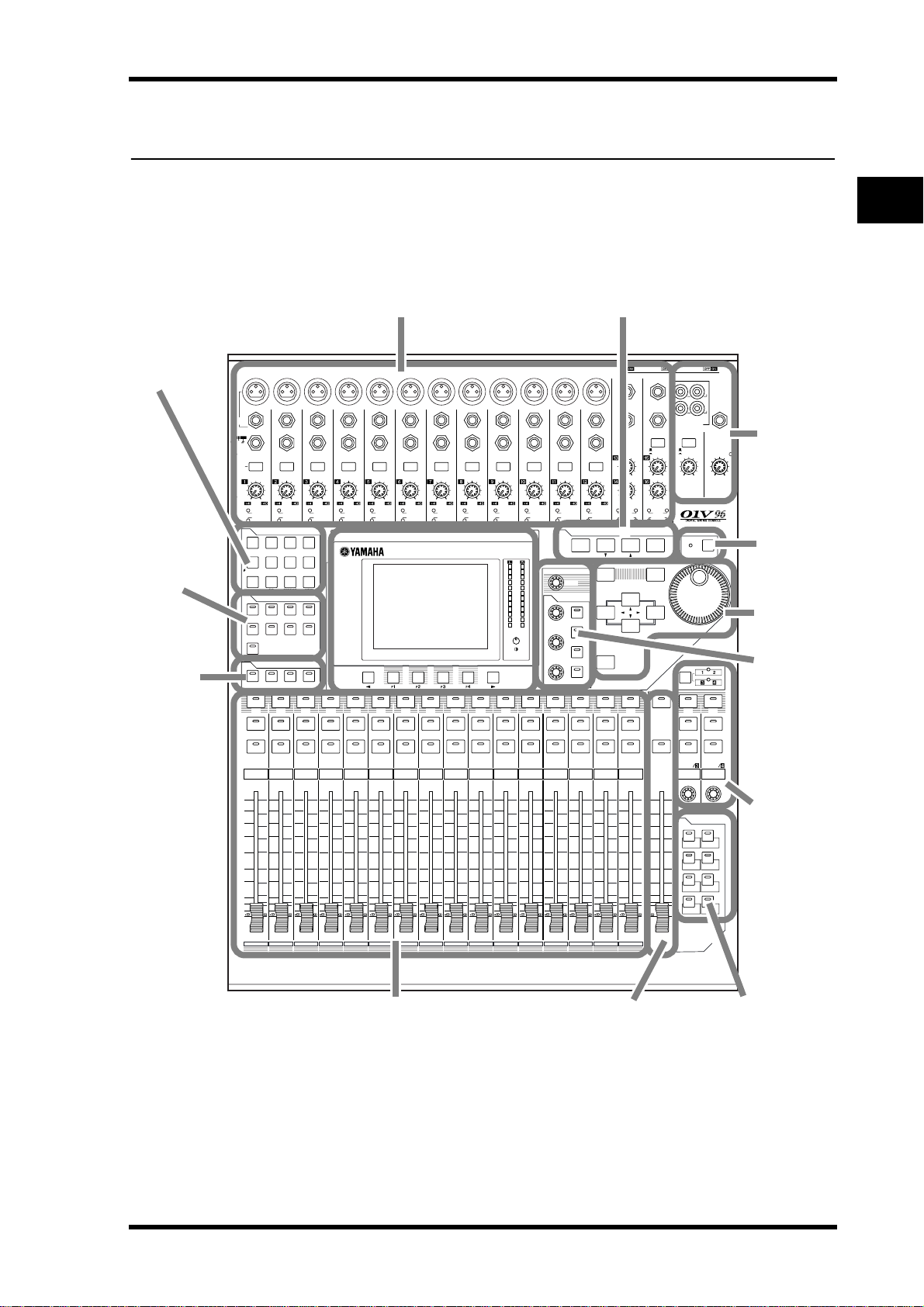
Control Surface . . . . . . . . . . . . . . . . . . . . . . . . . . . . . . . . . . . . . . . . . . . . . . . . . . . . . 13
Rear Panel . . . . . . . . . . . . . . . . . . . . . . . . . . . . . . . . . . . . . . . . . . . . . . . . . . . . . . . . . 23
Installing an Optional Card . . . . . . . . . . . . . . . . . . . . . . . . . . . . . . . . . . . . . . . . . . . 26
3 Operating Basics . . . . . . . . . . . . . . . . . . . . . . . . . . . . . . . . . 27
About the Display . . . . . . . . . . . . . . . . . . . . . . . . . . . . . . . . . . . . . . . . . . . . . . . . . . . 27
Selecting Display Pages . . . . . . . . . . . . . . . . . . . . . . . . . . . . . . . . . . . . . . . . . . . . . . . 28
Display Interface . . . . . . . . . . . . . . . . . . . . . . . . . . . . . . . . . . . . . . . . . . . . . . . . . . . . 29
Selecting Layers . . . . . . . . . . . . . . . . . . . . . . . . . . . . . . . . . . . . . . . . . . . . . . . . . . . . . 31
Selecting Channels . . . . . . . . . . . . . . . . . . . . . . . . . . . . . . . . . . . . . . . . . . . . . . . . . . 32
Selecting Fader Modes . . . . . . . . . . . . . . . . . . . . . . . . . . . . . . . . . . . . . . . . . . . . . . . 33
Metering . . . . . . . . . . . . . . . . . . . . . . . . . . . . . . . . . . . . . . . . . . . . . . . . . . . . . . . . . . 34
4 Connections and Setup . . . . . . . . . . . . . . . . . . . . . . . . . . . . 37
Connections . . . . . . . . . . . . . . . . . . . . . . . . . . . . . . . . . . . . . . . . . . . . . . . . . . . . . . . 37
Wordclock Connections and Settings . . . . . . . . . . . . . . . . . . . . . . . . . . . . . . . . . . . 40
Input and Output Patching . . . . . . . . . . . . . . . . . . . . . . . . . . . . . . . . . . . . . . . . . . . 43
5 Tutorial . . . . . . . . . . . . . . . . . . . . . . . . . . . . . . . . . . . . . . . . 47
Connections and Setup . . . . . . . . . . . . . . . . . . . . . . . . . . . . . . . . . . . . . . . . . . . . . . 47
Initial Track Recording . . . . . . . . . . . . . . . . . . . . . . . . . . . . . . . . . . . . . . . . . . . . . . 49
Overdubbing to Other Tracks . . . . . . . . . . . . . . . . . . . . . . . . . . . . . . . . . . . . . . . . . 60
Mixing Recorded Tracks into Stereo (Mixdown) . . . . . . . . . . . . . . . . . . . . . . . . . 63
6 Analog I/O & Digital I/O . . . . . . . . . . . . . . . . . . . . . . . . . . . 69
Analog Inputs & Outputs . . . . . . . . . . . . . . . . . . . . . . . . . . . . . . . . . . . . . . . . . . . . . 69
Digital Inputs & Outputs . . . . . . . . . . . . . . . . . . . . . . . . . . . . . . . . . . . . . . . . . . . . . 71
Converting Sampling Rates of Signals Received at I/O Card Inputs . . . . . . . . . . 72
Monitoring Digital Input Channel Status . . . . . . . . . . . . . . . . . . . . . . . . . . . . . . . 73
Dithering Digital Outputs . . . . . . . . . . . . . . . . . . . . . . . . . . . . . . . . . . . . . . . . . . . . 74
Setting the Transfer Format for Higher Sampling Rates . . . . . . . . . . . . . . . . . . . . 75
7 Input Channels . . . . . . . . . . . . . . . . . . . . . . . . . . . . . . . . . . 77
About Input Channels . . . . . . . . . . . . . . . . . . . . . . . . . . . . . . . . . . . . . . . . . . . . . . . 77
Setting the Input Channels from the Display . . . . . . . . . . . . . . . . . . . . . . . . . . . . . 79
Setting the Input Channels from the Control Surface . . . . . . . . . . . . . . . . . . . . . . 90
Pairing Input Channels . . . . . . . . . . . . . . . . . . . . . . . . . . . . . . . . . . . . . . . . . . . . . . 92
Naming Input Channels . . . . . . . . . . . . . . . . . . . . . . . . . . . . . . . . . . . . . . . . . . . . . . 94
8 Bus Outs . . . . . . . . . . . . . . . . . . . . . . . . . . . . . . . . . . . . . . . . 97
About Stereo Out . . . . . . . . . . . . . . . . . . . . . . . . . . . . . . . . . . . . . . . . . . . . . . . . . . . 97
Bus Out 1–8 . . . . . . . . . . . . . . . . . . . . . . . . . . . . . . . . . . . . . . . . . . . . . . . . . . . . . . . . 98
Setting the Stereo Out and Bus Out 1–8 from the Display . . . . . . . . . . . . . . . . . . 99
Setting the Stereo Out and Bus Out 1–8 from the Control Surface . . . . . . . . . . . 104
Pairing Buses or Aux Sends . . . . . . . . . . . . . . . . . . . . . . . . . . . . . . . . . . . . . . . . . . . 105
Attenuating Output Signals . . . . . . . . . . . . . . . . . . . . . . . . . . . . . . . . . . . . . . . . . . . 106
Naming the Stereo Out and Bus Outs . . . . . . . . . . . . . . . . . . . . . . . . . . . . . . . . . . 107
9 Aux Outs . . . . . . . . . . . . . . . . . . . . . . . . . . . . . . . . . . . . . . . 109
Aux Out 1–8 . . . . . . . . . . . . . . . . . . . . . . . . . . . . . . . . . . . . . . . . . . . . . . . . . . . . . . . 109
Setting Aux Out 1–8 from the Display . . . . . . . . . . . . . . . . . . . . . . . . . . . . . . . . . . 110
Viewing Aux Out Settings . . . . . . . . . . . . . . . . . . . . . . . . . . . . . . . . . . . . . . . . . . . . 112
Setting Aux Out 1–8 from the Control Surface . . . . . . . . . . . . . . . . . . . . . . . . . . . 113
01V96 Version 2—Owner’s Manual
Page 9

Contents
Setting Aux Send Levels . . . . . . . . . . . . . . . . . . . . . . . . . . . . . . . . . . . . . . . . . . . . . . 113
Viewing Aux Send Settings for Multiple Channels . . . . . . . . . . . . . . . . . . . . . . . . 117
Panning Aux Sends . . . . . . . . . . . . . . . . . . . . . . . . . . . . . . . . . . . . . . . . . . . . . . . . . . 119
Copying Channel Fader Positions to Aux Sends . . . . . . . . . . . . . . . . . . . . . . . . . . 120
10 Input & Output Patching . . . . . . . . . . . . . . . . . . . . . . . . . . 121
Input Patching . . . . . . . . . . . . . . . . . . . . . . . . . . . . . . . . . . . . . . . . . . . . . . . . . . . . . . 121
Output Patching . . . . . . . . . . . . . . . . . . . . . . . . . . . . . . . . . . . . . . . . . . . . . . . . . . . . 123
Patching Direct Outs . . . . . . . . . . . . . . . . . . . . . . . . . . . . . . . . . . . . . . . . . . . . . . . . . 125
Insert Patching . . . . . . . . . . . . . . . . . . . . . . . . . . . . . . . . . . . . . . . . . . . . . . . . . . . . . . 127
11 Monitoring . . . . . . . . . . . . . . . . . . . . . . . . . . . . . . . . . . . . . 131
Monitor . . . . . . . . . . . . . . . . . . . . . . . . . . . . . . . . . . . . . . . . . . . . . . . . . . . . . . . . . . . 131
Monitor and Solo Setup . . . . . . . . . . . . . . . . . . . . . . . . . . . . . . . . . . . . . . . . . . . . . . 132
Using the Monitor . . . . . . . . . . . . . . . . . . . . . . . . . . . . . . . . . . . . . . . . . . . . . . . . . . . 133
Using the Solo Function . . . . . . . . . . . . . . . . . . . . . . . . . . . . . . . . . . . . . . . . . . . . . . 134
12 Surround Pan . . . . . . . . . . . . . . . . . . . . . . . . . . . . . . . . . . . 135
About Surround Pan . . . . . . . . . . . . . . . . . . . . . . . . . . . . . . . . . . . . . . . . . . . . . . . . . 135
Setting Up and Selecting Surround Pan Modes . . . . . . . . . . . . . . . . . . . . . . . . . . . 136
Surround Panning . . . . . . . . . . . . . . . . . . . . . . . . . . . . . . . . . . . . . . . . . . . . . . . . . . . 142
9
13 Grouping Channels & Linking Parameters . . . . . . . . . . . . . 149
Grouping & Linking . . . . . . . . . . . . . . . . . . . . . . . . . . . . . . . . . . . . . . . . . . . . . . . . . 149
Using Fader Groups and Mute Groups . . . . . . . . . . . . . . . . . . . . . . . . . . . . . . . . . . 150
Using Fader Group Master . . . . . . . . . . . . . . . . . . . . . . . . . . . . . . . . . . . . . . . . . . . . 152
Using Mute Group Master . . . . . . . . . . . . . . . . . . . . . . . . . . . . . . . . . . . . . . . . . . . . 153
Linking EQ and Compressor Parameters . . . . . . . . . . . . . . . . . . . . . . . . . . . . . . . . 154
14 Internal Effects . . . . . . . . . . . . . . . . . . . . . . . . . . . . . . . . . . 157
About the Internal Effects . . . . . . . . . . . . . . . . . . . . . . . . . . . . . . . . . . . . . . . . . . . . . 157
Using Effects Processors via Aux Sends . . . . . . . . . . . . . . . . . . . . . . . . . . . . . . . . . . 158
Inserting the Internal Effects into Channels . . . . . . . . . . . . . . . . . . . . . . . . . . . . . . 160
Editing Effects . . . . . . . . . . . . . . . . . . . . . . . . . . . . . . . . . . . . . . . . . . . . . . . . . . . . . . 161
About Add-On Effects . . . . . . . . . . . . . . . . . . . . . . . . . . . . . . . . . . . . . . . . . . . . . . . 162
About Plug-Ins . . . . . . . . . . . . . . . . . . . . . . . . . . . . . . . . . . . . . . . . . . . . . . . . . . . . . 163
15 Scene Memories . . . . . . . . . . . . . . . . . . . . . . . . . . . . . . . . . . 165
About Scene Memories . . . . . . . . . . . . . . . . . . . . . . . . . . . . . . . . . . . . . . . . . . . . . . . 165
What is Stored in a Scene? . . . . . . . . . . . . . . . . . . . . . . . . . . . . . . . . . . . . . . . . . . . . 165
About Scene Numbers . . . . . . . . . . . . . . . . . . . . . . . . . . . . . . . . . . . . . . . . . . . . . . . 166
Storing and Recalling Scenes . . . . . . . . . . . . . . . . . . . . . . . . . . . . . . . . . . . . . . . . . . 167
Auto Scene Memory Update . . . . . . . . . . . . . . . . . . . . . . . . . . . . . . . . . . . . . . . . . . 169
Fading Scenes . . . . . . . . . . . . . . . . . . . . . . . . . . . . . . . . . . . . . . . . . . . . . . . . . . . . . . . 170
Recalling Scenes Safely . . . . . . . . . . . . . . . . . . . . . . . . . . . . . . . . . . . . . . . . . . . . . . . 172
Sorting Scenes . . . . . . . . . . . . . . . . . . . . . . . . . . . . . . . . . . . . . . . . . . . . . . . . . . . . . . 173
Copying and Pasting a Scene (Global Paste) . . . . . . . . . . . . . . . . . . . . . . . . . . . . . 173
16 Libraries . . . . . . . . . . . . . . . . . . . . . . . . . . . . . . . . . . . . . . . 175
About the Libraries . . . . . . . . . . . . . . . . . . . . . . . . . . . . . . . . . . . . . . . . . . . . . . . . . . 175
General Library Operation . . . . . . . . . . . . . . . . . . . . . . . . . . . . . . . . . . . . . . . . . . . . 175
Using Libraries . . . . . . . . . . . . . . . . . . . . . . . . . . . . . . . . . . . . . . . . . . . . . . . . . . . . . . 177
17 Remote Control . . . . . . . . . . . . . . . . . . . . . . . . . . . . . . . . . . 189
About Remote Function . . . . . . . . . . . . . . . . . . . . . . . . . . . . . . . . . . . . . . . . . . . . . . 189
Pro Tools Remote Layer . . . . . . . . . . . . . . . . . . . . . . . . . . . . . . . . . . . . . . . . . . . . . . 190
Nuendo/Cubase SX Remote Layer . . . . . . . . . . . . . . . . . . . . . . . . . . . . . . . . . . . . . . 206
Other DAW Remote Layer . . . . . . . . . . . . . . . . . . . . . . . . . . . . . . . . . . . . . . . . . . . . 206
MIDI Remote Layer . . . . . . . . . . . . . . . . . . . . . . . . . . . . . . . . . . . . . . . . . . . . . . . . . 207
Machine Control Function . . . . . . . . . . . . . . . . . . . . . . . . . . . . . . . . . . . . . . . . . . . . 212
01V96 Version 2—Owner’s Manual
Page 10

10
Contents
18 MIDI . . . . . . . . . . . . . . . . . . . . . . . . . . . . . . . . . . . . . . . . . . . 215
MIDI & the 01V96 . . . . . . . . . . . . . . . . . . . . . . . . . . . . . . . . . . . . . . . . . . . . . . . . . . 215
MIDI Port Setup . . . . . . . . . . . . . . . . . . . . . . . . . . . . . . . . . . . . . . . . . . . . . . . . . . . . 216
Assigning Scenes to Program Changes for Remote Recall . . . . . . . . . . . . . . . . . . 219
Assigning Parameters to Control Changes for Real-time Control . . . . . . . . . . . . 220
Controlling Parameters by Using Parameter Changes . . . . . . . . . . . . . . . . . . . . . 225
Transmitting Parameter Settings via MIDI (Bulk Dump) . . . . . . . . . . . . . . . . . . 226
19 Other Functions . . . . . . . . . . . . . . . . . . . . . . . . . . . . . . . . . . 229
Changing the Input and Output Channel Names . . . . . . . . . . . . . . . . . . . . . . . . . 229
Setting Preferences . . . . . . . . . . . . . . . . . . . . . . . . . . . . . . . . . . . . . . . . . . . . . . . . . . 230
Creating a Custom Layer by Combining Channels (User Assignable Layer) . . . 233
Using the Oscillator . . . . . . . . . . . . . . . . . . . . . . . . . . . . . . . . . . . . . . . . . . . . . . . . . 234
Using the User Defined Keys . . . . . . . . . . . . . . . . . . . . . . . . . . . . . . . . . . . . . . . . . . 235
Using Operation Lock . . . . . . . . . . . . . . . . . . . . . . . . . . . . . . . . . . . . . . . . . . . . . . . 237
Cascading Consoles . . . . . . . . . . . . . . . . . . . . . . . . . . . . . . . . . . . . . . . . . . . . . . . . . 238
Checking the Battery and the System Version . . . . . . . . . . . . . . . . . . . . . . . . . . . . 242
Initializing the 01V96 . . . . . . . . . . . . . . . . . . . . . . . . . . . . . . . . . . . . . . . . . . . . . . . . 243
Calibrating the Faders . . . . . . . . . . . . . . . . . . . . . . . . . . . . . . . . . . . . . . . . . . . . . . . 244
Appendix A: Parameter Lists . . . . . . . . . . . . . . . . . . . . . . . . . . . 247
USER DEFINED KEYS . . . . . . . . . . . . . . . . . . . . . . . . . . . . . . . . . . . . . . . . . . . . . . . 247
USER DEFINED KEYS Initial Assignments . . . . . . . . . . . . . . . . . . . . . . . . . . . . . . 249
Input Patch Parameters . . . . . . . . . . . . . . . . . . . . . . . . . . . . . . . . . . . . . . . . . . . . . . 249
Initial Input Patch Settings . . . . . . . . . . . . . . . . . . . . . . . . . . . . . . . . . . . . . . . . . . . 251
Output Patch Parameters . . . . . . . . . . . . . . . . . . . . . . . . . . . . . . . . . . . . . . . . . . . . . 253
Initial Output Patch Settings . . . . . . . . . . . . . . . . . . . . . . . . . . . . . . . . . . . . . . . . . . 255
User Defined Remote Layer Initial Bank Settings . . . . . . . . . . . . . . . . . . . . . . . . . 256
Effects Parameters . . . . . . . . . . . . . . . . . . . . . . . . . . . . . . . . . . . . . . . . . . . . . . . . . . . 260
Effects and tempo synchronization . . . . . . . . . . . . . . . . . . . . . . . . . . . . . . . . . . . . . 270
Preset EQ Parameters . . . . . . . . . . . . . . . . . . . . . . . . . . . . . . . . . . . . . . . . . . . . . . . . 271
Preset Gate Parameters (fs = 44.1 kHz) . . . . . . . . . . . . . . . . . . . . . . . . . . . . . . . . . 272
Preset Compressor Parameters (fs = 44.1 kHz) . . . . . . . . . . . . . . . . . . . . . . . . . . . 273
Dynamics Parameters . . . . . . . . . . . . . . . . . . . . . . . . . . . . . . . . . . . . . . . . . . . . . . . . 275
Appendix B: Specifications . . . . . . . . . . . . . . . . . . . . . . . . . . . . 280
General Spec . . . . . . . . . . . . . . . . . . . . . . . . . . . . . . . . . . . . . . . . . . . . . . . . . . . . . . . 280
Libraries . . . . . . . . . . . . . . . . . . . . . . . . . . . . . . . . . . . . . . . . . . . . . . . . . . . . . . . . . . . 285
Analog Input Spec . . . . . . . . . . . . . . . . . . . . . . . . . . . . . . . . . . . . . . . . . . . . . . . . . . . 286
Analog Output Specs . . . . . . . . . . . . . . . . . . . . . . . . . . . . . . . . . . . . . . . . . . . . . . . . 286
Digital Input Spec . . . . . . . . . . . . . . . . . . . . . . . . . . . . . . . . . . . . . . . . . . . . . . . . . . . 287
Digital Output Spec . . . . . . . . . . . . . . . . . . . . . . . . . . . . . . . . . . . . . . . . . . . . . . . . . 287
I/O SLOT Spec . . . . . . . . . . . . . . . . . . . . . . . . . . . . . . . . . . . . . . . . . . . . . . . . . . . . . 287
CONTROL I/O Spec . . . . . . . . . . . . . . . . . . . . . . . . . . . . . . . . . . . . . . . . . . . . . . . . . 288
Dimensions . . . . . . . . . . . . . . . . . . . . . . . . . . . . . . . . . . . . . . . . . . . . . . . . . . . . . . . . 288
Appendix C: MIDI . . . . . . . . . . . . . . . . . . . . . . . . . . . . . . . . . . . . 289
Scene Memory to Program Change Table . . . . . . . . . . . . . . . . . . . . . . . . . . . . . . . 289
Initial Parameter to Control Change Table . . . . . . . . . . . . . . . . . . . . . . . . . . . . . . 290
MIDI Data Format . . . . . . . . . . . . . . . . . . . . . . . . . . . . . . . . . . . . . . . . . . . . . . . . . . 306
Appendix D: Options . . . . . . . . . . . . . . . . . . . . . . . . . . . . . . . . . 318
Index . . . . . . . . . . . . . . . . . . . . . . . . . . . . . . . . . . . . . . . . . . . . . 319
MIDI Implementation Chart . . . . . . . . . . . . . . . . . . . . End of Manual
01V96 Block Diagram . . . . . . . . . . . . . . . . . . . . . . . . . End of Manual
01V96 Level Diagram . . . . . . . . . . . . . . . . . . . . . . . . . End of Manual
01V96 Version 2—Owner’s Manual
Page 11

1 Welcome
Thank you for choosing the Yamaha 01V96 Digital Mixing Console.
The compact 01V96 Digital Console features 24-bit/96 kHz digital audio processing with-
out compromise, as well as 40-channel simultaneous mixing. The 01V96 covers a broad
range of needs and applications, including multi-track recording, 2-channel mixdown, and
cutting-edge surround sound production. This integrated, comprehensive audio system
features remote control function for DAWs (Digital Audio Workstations) as popularized by
the DM2000 and 02R96 Digital Mixing Consoles.
The 01V96 offers the following features:
Hardware Features
• 100-mm motorized faders x 17
•Faders can set levels for Input Channels, Aux send levels, and Bus Outs.
•Four selectable software layers determine the function of channel faders.
• 320 x 240 dot LCD display
•Buttons and controls in the SELECTED CHANNEL section enable direct editing of
channel EQ parameters.
•8 USER-DEFINED KEYS enable you to assign functions to control 01V96 internal
parameters.
•ADAT optical connectors
•Expansion slot for optional digital I/O, AD, and DA cards.
Welcome
11
1
Welcome
■
■
■
Sonic Specifications
• Linear 24-bit, 128-times oversampling A/D converters
• Linear 24-bit, 128-times oversampling D/A converters
• 20 Hz through 40 kHz frequency response at 96 kHz sampling rate.
• 106 dB typical dynamic range
• 32-bit internal signal processing (58-bit accumulator)
Inputs and Outputs
• 12 mic/line inputs with switchable +48 V phantom power and 4 line inputs
• 12 analog inserts
•Any Bus Outs or Channel Inserts can be routed to four Omni Outs.
•Individual outputs for Stereo Out and Monitor Out
•Analog 2TR In and Out for use with Tape In and Out signals
•An optional card installed in the slot permits a maximum of 16 inputs/outputs.
•Digital 2TR In and Out for consumer-format digital audio signals
•Double Channel support for recording and playing at 88.2/96 kHz on 44.1/48 kHz legacy multi-track digital recorders.
•You can cascade two 01V96s while remaining in the digital domain.
•Input patches enable assignment of input signals to desired signal paths.
•Output patches enable assignment of Bus Out signals and Input Channel Direct Outs to
desired output jacks.
01V96 Version 2—Owner’s Manual
Page 12

12
Chapter 1—Welcome
Channel Configuration
• 32 Input Channels and four ST IN channels can be mixed at a time. Group multiple
channels and pair channels for stereo.
•Eight Bus Outs and eight Aux Sends. Bus Outs 1-8 can be routed to Stereo Buses for use
as Group Buses.
•Channel library for storing and recalling the channel settings for each Input Channel
and Output Channel
•Four-band EQ on each channel
•Dynamics processors on all channels (excluding ST IN channels)
•Dynamics processor settings and EQ settings can be stored in libraries and recalled.
Effects
•Four high-quality multi-channel effects (Apply effects via Aux Sends or Channel
Inserts)
• Effect library for storing and recalling effect settings.
•Optional Add-On Effects packages for adding effects that utilize a variety of new algorithms.
■ Scene Memory
•Scene memories for storing and recalling mix settings as Scenes
■ Surround Sound
•Supports 3-1, 5.1, and 6.1 channel surround sound production
•Surround channel outputs can be assigned to suit connected devices.
■ Remote Control
•Control and manage your 01V96 from your Mac or PC using bundled Studio Manager
software.
•Remote Layer for remote control of Pro Tools, Nuendo, Cubase SX, and other DAWs
that support the Pro Tools protocol
•Control an external recorder via MMC commands.
■ MIDI
•Equipped with MIDI ports and a USB port for computer connection
•Scene recall and mix parameter changes via MIDI
■
■
01V96 Version 2—Owner’s Manual
Page 13
Control Surface & Rear Panel 13
SOLO SOLO
ON ON
SOLOONSOLOONSOLOONSOLOONSOLOONSOLOONSOLOONSOLOONSOLOONSOLOONSOLOONSOLOONSOLOONSOLO
ON
SOLOONSOLO
ONON
PEAK
SIGNAL
PEAK
SIGNAL
PEAK
SIGNAL
PEAK
SIGNAL
PEAK
SIGNAL
PEAK
SIGNAL
PEAK
SIGNAL
PEAK
SIGNAL
PEAK
SIGNAL
PEAK
SIGNAL
PEAK
SIGNAL
PEAK
SIGNAL
PEAK
SIGNAL
PEAK
SIGNAL
1-16 17-32 MASTER REMOTE
LAYER
SEL SEL SEL SEL SEL SEL SEL SEL SEL SEL SEL SEL SEL SEL SEL SEL SEL SELSEL
ST IN
ENTER
EQUALIZER
HIGH
HIGH-MID
LOW-MID
LOW
Q
FREQUENCY
GAIN
STEREO
SELECTED CHANNEL
PAN
DEC INC
SOLO CLEAR
RECALL
STORE
SCENE MEMORY
PHONES
MONITOR
OUT
MONITOR
2TR IN
CH15
/
16
2TR IN
LEVEL
PHONES
LEVEL
0
10
0
10
+4
-26
GAIN
+4
-26
GAIN
+4
-26
GAIN
GAIN
+4
-26
GAIN
20dB
-16
-60
GAIN
20dB
-16
-60
GAIN
20dB20dB20dB20dB20dB20dB20dB20dB20dB20dB
-16
-60
GAIN
-16
-60
GAIN
-16
-60
GAIN
-16
-60
GAIN
-16
-60
GAIN
-16
-60
GAIN
-16
-60
GAIN
-16
-60
GAIN
-16
-60
GAIN
-16
-60
PAD
FADER MODE
DISPLAY ACCESS
AUX 1
AUX 1 AUX 2 AUX 3 AUX 4 AUX 5 AUX 6 AUX 7 AUX 8 BUS 1 BUS 2 BUS 3 BUS 4 BUS 5 BUS 6 BUS 7 BUS 8
AUX 2 AUX 3 AUX 4
AUX 8AUX 7AUX 6AUX 5
HOME (METER)
DYNAMICS
EQ EFFECT VIEW
PATCH
UTILITYMIDISCENE
DIO/SETUP
/ INSERT/
DELAY
PAN/
ROUTING
PAIR/
GROUP
ABABABABABABABABABABABA
B
16
1513
121110987643215
14
INSERT I
/
O INSERT I/O INSERT I/O INSERT I/O INSERT I/O INSERT I/O INSERT I/O INSERT I/O INSERT I/O INSERT I/OINSERT I/O INSERT I/O
L
R
IN OUT
2TR
-10dBV (UNBAL)
PHANTOM +48V
CH9-12CH5-8CH1-4
INPUT
(BAL)
INSERT
OUTIN
(UNBAL)
ST IN 1 ST IN 2
USER DEFINED
KEYS
12
34
56
78
55
5
+10
5
1010
10
1515
15
2020
20
303030
30
4040
40
5050
50
6060
7070
20
30
40
40
50
50
60
70
00
5
10
15
20
0
0
5
+10
5
10
15
30
20
30
40
40
50
50
60
70
20
30
40
40
50
50
60
70
20
30
40
40
50
50
60
70
20
30
40
40
50
50
60
70
20
30
40
40
50
50
60
70
15
0
5
10
15
20
0
5
+10
5
10
0
30
15
5
10
15
20
0
5
+10
5
10
0
30
15
5
10
15
20
0
5
+10
5
10
0
30
15
5
10
15
20
0
5
+10
5
10
0
30
15
20
30
40
40
50
50
60
70
30
15
20
30
40
40
20
30
40
20
30
40
20
30
40
50
50505050
20
30
40
50
20
30
40
50
60
70
40
50
60
70
40
50
60
70
40
50
60
70
40
50
60
70
40
50
60
70
40
50
60
70
40
50
60
70
30
15
5
10
15
20
0
5
+10
5
10
0
5
10
15
20
0
5
+10
5
10
0
5
10
15
20
0
30
5
10
15
20
0
30
5
10
15
20
0
30
5
10
15
20
0
30
5
10
15
20
0
303030
5
10
15
20
0
5
10
15
20
0
5
10
15
20
0
5
+10
5
10
0
15
5
+10
5
10
0
15
5
+10
5
10
0
15
5
+10
5
10
0
15
20
30
40
50
15 15
20
30
40
50
15
5
+10
5
10
0
5
+10
5
10
0
5
+10
5
10
0
5
+10
5
10
0
123456
123456
7
891011 12
7
891011 12
13 14 15 16
13 14 15 16
32313029282726252423222120191817
STEREO
13 14 15 16
OVER
0
-3
-6
-9
-12
-15
-18
-24
-30
-36
-48
AD Input Section (p. 14)
SELECTED
CHANNEL
Section (p. 20)
Monitor Out
& Headphones Section (p. 15)
SOLO Section
(p. 22)
Channel Strip Section (p. 16) STEREO Section (p. 16) USER DEFINED KEYS
Section (p. 21)
Data Entry
Section (p. 22)
LAYER Section
(p. 19)
SCENE MEMORY Section (p. 21)
Display Section
(p. 19)
DISPLAY ACCESS
Section (p. 18)
ST IN Section
(p. 17)
FADER MODE
Section (p. 17)
2 Control Surface & Rear Panel
Control Surface
2
Control Surface & Rear Panel
01V96 Version 2—Owner’s Manual
Page 14
14 Chapter 2—Control Surface & Rear Panel
AD Input Section
CH1-4
121110943215
1513
1
3
4
5
6
7
OUTIN
(UNBAL)
A
A
B
INPUT
(BAL)
INSERT
/
O INSERT I/O INSERT I/O INSERT I/O INSERT I/O INSERT I/O INSERT I/O INSERT I/O INSERT I/O
INSERT I
PAD
-60
-16
GAIN
PEAK
SIGNAL
A
B
B
-60
-16
GAIN
PEAK
SIGNAL
A
A
B
B
-60
-60
-60
-16
GAIN
PEAK
SIGNAL
-16
-16
GAIN
PEAK
SIGNAL
GAIN
PEAK
SIGNAL
A
A
B
B
20dB20dB20dB20dB20dB20dB20dB
-60
-16
GAIN
PEAK
SIGNAL
-16
GAIN
PEAK
SIGNAL
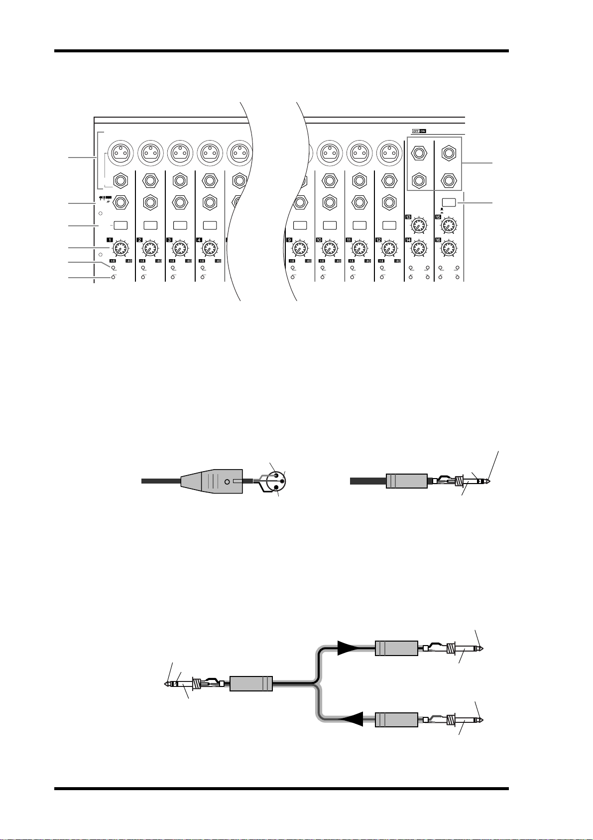
A INPUT connectors A/B
INPUT A connectors are balanced XLR-3-31-type connectors that accept line-level and
microphone signals. Each of the phantom [+48V] switches on the rear panel turns on or off
the +48V phantom power feed to the corresponding input. INPUT B connectors are balanced TRS phone-type connectors that accept line-level and microphone signals. The nominal signal level of both types of connectors ranges from –60 dB to +4 dB. Phantom power
is not supplied to these connectors.
If you connect cables to INPUT A and INPUT B connectors of the same number, only the
signal from INPUT B is effective.
Male XLR plug
1 (ground)
3 (cold)
A
B
-60
A
B
20dB
-16
GAIN
PEAK
SIGNAL
20dB
-60
-16
GAIN
PEAK
SIGNAL
1/4" TRS phone plug
14
-26
+4
GAIN
-26
-60
+4
GAIN
PEAK
13 14 15 16
SIGNAL
16
CH15/16
2TR IN
-26
+4
GAIN
-26
+4
GAIN
PEAK
SIGNAL
Ring (cold)
2
8
Tip (hot)
2 (hot)
Sleeve (ground)
B INPUT connectors 13–16
These balanced TRS phone-type connectors accept line-level signals. The nominal signal
level ranges from –26 dB to +4 dB. INPUT 15 & 16 connectors are available only when the
AD 15/16 button is turned off (page 15).
C INSERT I/O connectors
These unbalanced TRS phone-type connectors are used for channel insert ins and outs. Use
a split cable to insert an external effects processor to AD input channels.
Tip (send)
Sleeve
(ground)
Tip (return)
Tip (send)
Ring (return)
Sleeve (ground)
Connect to INSERT jack
1/4" phone plug
1/4" phone plug
To processor’s input
1/4" phone plug
Sleeve (ground)
From processor’s output
01V96 Version 2—Owner’s Manual
Page 15
Control Surface 15
D PAD switches
These switches turn on or off the 20 dB pad (attenuator) for each AD Input.
E GAIN controls
These controls adjust input sensitivity for each AD Input. Input sensitivity is –16 dB to
–60 dB when the Pad is off, and +4 dB to –40 dB when the Pad is on.
F PEAK indicators
These indicators light up when the input signal level is 3 dB below clipping. Adjust the Pad
switch and GAIN control so that the indicator rarely lights up at signal peak.
G SIGNAL indicators
These indicators light up when the input signal level exceeds –34 dB.
H AD15/16 selector
This button selects AD Input Channel 15 and 16 signals. When the button is turned on
(pushed in), the 2TR IN signals (page 24) are selected. When the button is turned off
(raised), the INPUT 15 and 16 signals are selected.
Monitor Out & Headphones Section
CH9-12CH5-8
PHANTOM +48V
L
1
2
3
IN OUT
2TR
-10dBV (UNBAL)
MONITOR
2TR IN
0
LEVEL
MONITOR
OUT
R
5
PHONES
0
10
10
LEVEL
PHONES
4
2
Control Surface & Rear Panel
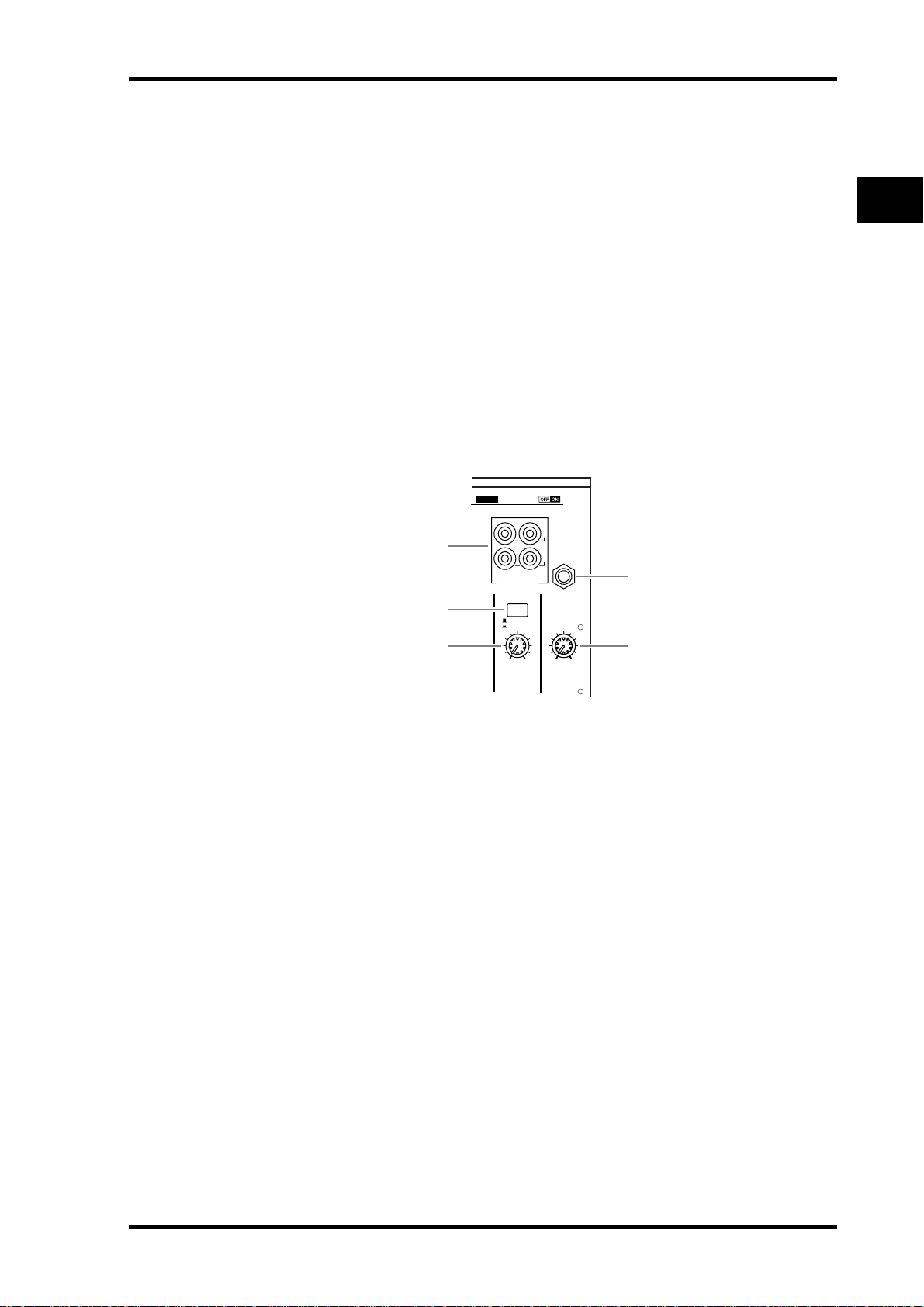
A 2TR IN/OUT connectors
These unbalanced RCA phono connectors input and output line-level signals, and are typically used to connect a master recorder.
When the AD15/16 selector in the AD Input section (8) is turned on (pushed in), the signals input at the 2TR IN connectors are routed to AD Input Channels 15 and 16. When the
Monitor Source selector (2) is turned on (pushed in), you can monitor the 2TR IN signals
from the MONITOR OUT connectors.
The 2TR OUT signals are always the same as the STEREO OUT signals.
B Monitor Source selector
This button selects the signals output from the MONITOR OUT connectors on the rear
panel. When this button is turned on (pushed in), you can monitor the signals input from
the 2TR IN connectors. When the button is turned off (raised), you can monitor the Stereo
Out signals or soloed channel signals.
C MONITOR LEVEL control
This control adjusts the monitoring level of the signals output from the MONITOR OUT
connectors.
D PHONES LEVEL control
This control sets the level of the PHONES. (See page 131 for more information on monitoring through the headphones.)
E PHONES jack
You can connect a set of stereo headphones to this stereo phone jack. The signals output
from the MONITOR OUT connectors are also output from this jack.
01V96 Version 2—Owner’s Manual
Page 16
16 Chapter 2—Control Surface & Rear Panel
Channel Strip Section
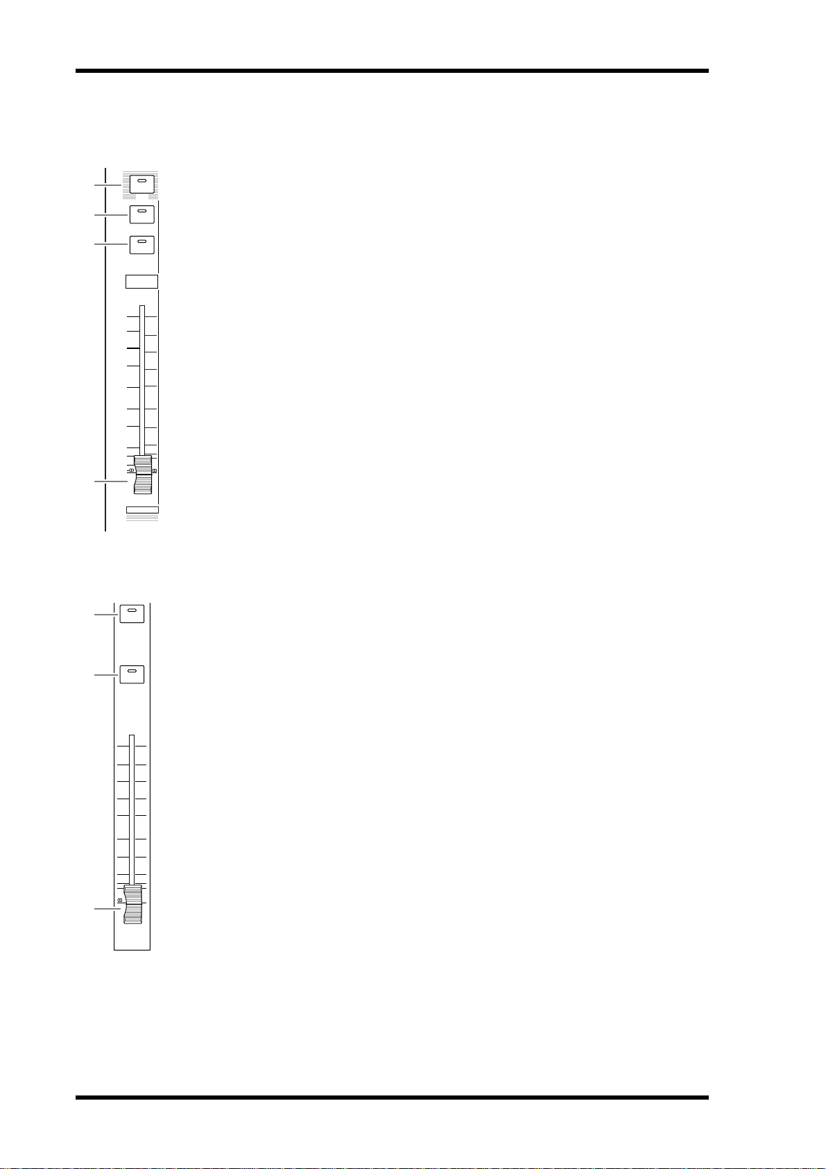
A [SEL] buttons
These buttons enable you to select desired channels. The [SEL] button indicator for the cur-
1
2
3
4
SEL
SOLO
ON
1
+10
0
5
5
0
10
5
15
20
10
15
30
20
40
50
30
60
40
70
50
1
17
AUX 1
rently-selected channel lights up. The channel selected by each [SEL] button depends on the
layer selected in the LAYER section (see page 19).
These buttons also allow you to create or cancel channel pairs, and add channels to (or
remove them from) Fader, Mute, EQ, and Compressor groups.
B [SOLO] buttons
These buttons solo the selected channels. The [SOLO] button indicator of the currently-soloed channel lights up.
C [ON] buttons
These buttons turn the selected channels on or off. The [ON] button indicators for On
channels light up.
D Channel faders
Depending on the button selected in the FADER MODE section (see page 17), these faders
adjust the selected channel input levels or the Bus Out or Aux Out levels.
1
2
3
STEREO Section
A [SEL] button
SEL
ON
0
5
10
15
20
30
40
50
60
70
STEREO
Selects the Stereo Out.
B [ON] button
Tu r ns the Stereo Out on or off.
C [STEREO] fader
This 100mm motorized fader adjusts the final output level of the Stereo Out.
01V96 Version 2—Owner’s Manual
Page 17
ST IN Section
Control Surface 17
1
2
3
4
ST IN
SEL SEL
SOLOONSOLO
ON
ST IN 1 ST IN 2
5
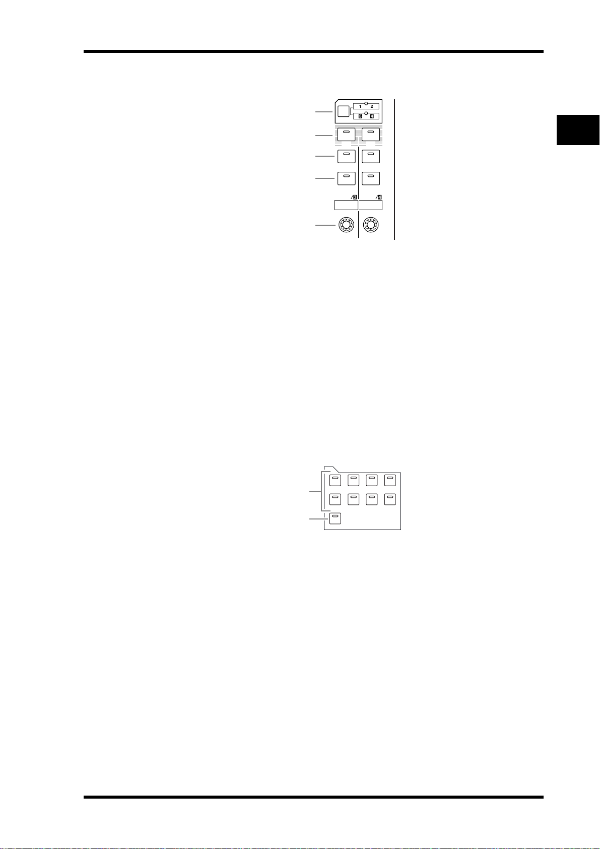
A [ST IN] button
This button selects an ST IN channel pair (ST IN Channels 1 & 2 or 3 & 4) which you can
control using the buttons and controls in the ST IN section. The indicators to the right of
the button indicate the available ST IN channels.
B [SEL] buttons
These buttons select the ST IN channel you want to control.
C [SOLO] buttons
These buttons solo the selected ST IN channels.
D [ON] buttons
These buttons turn the ST IN channels on or off.
2
Control Surface & Rear Panel
E Level controls
These controls adjust the ST IN channel levels.
FADER MODE Section
FADER MODE
1
2
A [AUX 1]–[AUX 8] buttons
These buttons enable you to select the Aux Send you wish to control. Pressing one of these
buttons switches the Fader mode (see page 33), and displays the corresponding Aux page.
(The selected button’s indicator lights up.)
You can now adjust the send level of signals routed from Input Channels to the corresponding Aux buses by using the faders.
B [HOME] button
This button recalls Meter pages that display Input Channel levels or Output Channel (Bus
Out, Aux Out, Stereo Out) levels (see page 34).
AUX 1 AUX 2 AUX 3 AUX 4
AUX 8AUX 7AUX 6AUX 5
HOME (METER)
01V96 Version 2—Owner’s Manual
Page 18

18 Chapter 2—Control Surface & Rear Panel
DISPLAY ACCESS Section
6
5
1 2 3
DISPLAY ACCESS
DIO/SETUP
DIO/SETUP
PAN/
/ INSERT/
ROUTING
DELAY
EQ EFFECT VIEW
DYNAMICS
PAIR/
GROUP
4
UTILITYMIDISCENE
UTILITYMIDISCENE
PATCH
7
8
9 J K L
A [SCENE] button
This button displays a Scene page, enabling you to store and recall Scenes (see page 165).
B [DIO/SETUP] button
This button displays a DIO/Setup page, enabling you to set up the 01V96, including digital
input and output setup and remote control setup (see pgaes 72, 192).
C [MIDI] button
This button displays a MIDI page, enabling you to make MIDI settings (see page 219).
D [UTILITY] button
This button displays a Utility page, enabling you to use the internal oscillators and view
information about installed optional cards.
E [ /INSERT/DELAY] button
This button displays a /INS/DLY page, enabling you to switch the signal phase, set the
signal to be inserted, or set the delay parameters (see pages 79, 127).
F [PAN/ROUTING] button
This button displays a Pan/Route page, enabling you to select a Bus to which the selected
channel signal is routed, adjust the selected channel pan settings, adjust the level of signals
routed from Buses 1–8 to the Stereo Bus, and adjust the stereo or surround pan settings (see
pages 85, 135).
G [PAIR/GROUP] button
This button displays a Pair/Grup page, enabling you to create or cancel channel pairs and
group multiple channel faders or [ON] buttons (see pages 93, 149).
H [PATCH] button
This button displays a Patch page, enabling you to patch input signals and Bus Out signals
to Input channels, or patch signals to the desired output connectors (see page 121).
I [DYNAMICS] button
This button displays a Dynamics page, enabling you to control channel gates and compressors (see page 81).
J [EQ] button
This button displays an EQ page, enabling you to set the equalizer and attenuator of the
selected channel (see page 84).
K [EFFECT] button
This button displays an Effect page, enabling you to edit the internal effects processors and
use optional plug-in cards (see page 161).
L [VIEW] button
This button displays a View page, enabling you to view and set mix parameters for a specific
channel (see page 87).
01V96 Version 2—Owner’s Manual
Page 19
Control Surface 19
LAYER Section
LAYER
1-16 17-32 MASTER REMOTE
1 2 3
A [1–16]/[17–32] buttons
These buttons select an Input Channel layer as the layer controlled in the Channel Strip section. When the [1–16] button is turned on, you can control Channels 1–16. When the
[17–32] button is turned on, you can control Channels 17–32. (See page 31 for more information on the Input Channel layers.)
B [MASTER] button
This button selects the Master Layer as the layer controlled in the Channel Strip section. You
can use this layer to control Bus Outs and AUX Sends. (See page 31 for more information
on the Master layer.)
C [REMOTE] button
This button selects the Remote Layer as the layer controlled in the Channel Strip section.
You can use this layer to control external MIDI devices or computer-based DAWs. (See
page 189 for more information on the Remote layer.)
2
Control Surface & Rear Panel
Tip: The ST IN section is not affected by the layer settings.
Display Section
1
STEREO
5
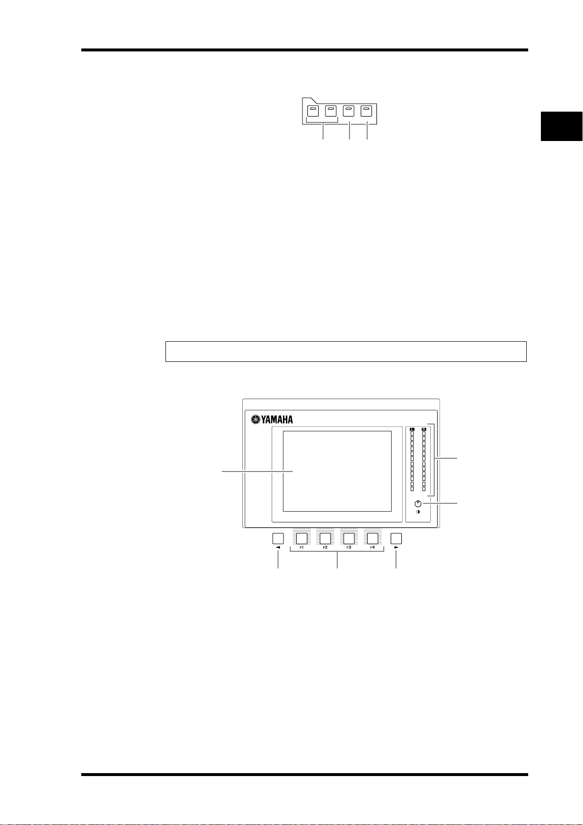
A Display
This is a 320 x 240 dot LCD display with a backlight.
B Stereo meters
These 12-segment level meters display the final output level of the Stereo Bus.
4
6
OVER
0
-3
-6
-9
-12
-15
-18
-24
-30
-36
-48
2
3
C Contrast control
This control adjusts the display contrast.
D [F1]–[F4] buttons
These buttons select a page from a multi-page screen. Selecting a tab at the bottom of the
screen using one of these buttons displays the corresponding page. (See page 28 for more
information on displaying a page.)
01V96 Version 2—Owner’s Manual
Page 20
20 Chapter 2—Control Surface & Rear Panel
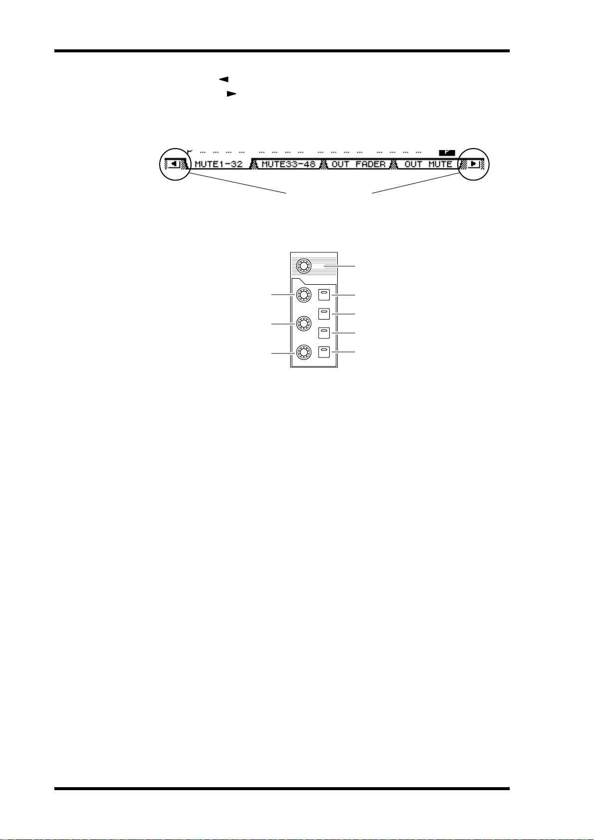
E Left Tab Scroll [ ] button
F Right Tab Scroll [ ] button
If there are more pages available than the four whose tabs are currently displayed, use these
buttons to display the additional tabs. These buttons are available only when the left or right
Tab Scroll arrow appears.
SELECTED CHANNEL Section
6
7
8
Tab Scroll arrow
SELECTED CHANNEL
PAN
EQUALIZER
HIGH
Q
HIGH-MID
FREQUENCY
LOW-MID
LOW
GAIN
1
2
3
4
5
A [PAN] control
This control adjusts the pan of the channel selected by the [SEL] button.
B [HIGH] button
C [HIGH-MID] button
D [LOW-MID] button
E [LOW] button
These buttons select the EQ band (HIGH, HIGH-MID, LOW-MID, LOW) of the channel
selected by the [SEL] button. The corresponding button indicator of the currently-selected
band lights up.
F [Q] control
This control adjusts the currently-selected band Q.
G [FREQUENCY] control
This control adjusts the currently-selected band frequency.
H [GAIN] control
This control adjusts the currently-selected band gain.
01V96 Version 2—Owner’s Manual
Page 21
SCENE MEMORY Section
Control Surface 21
SCENE MEMORY
STORE
1 3
2
RECALL
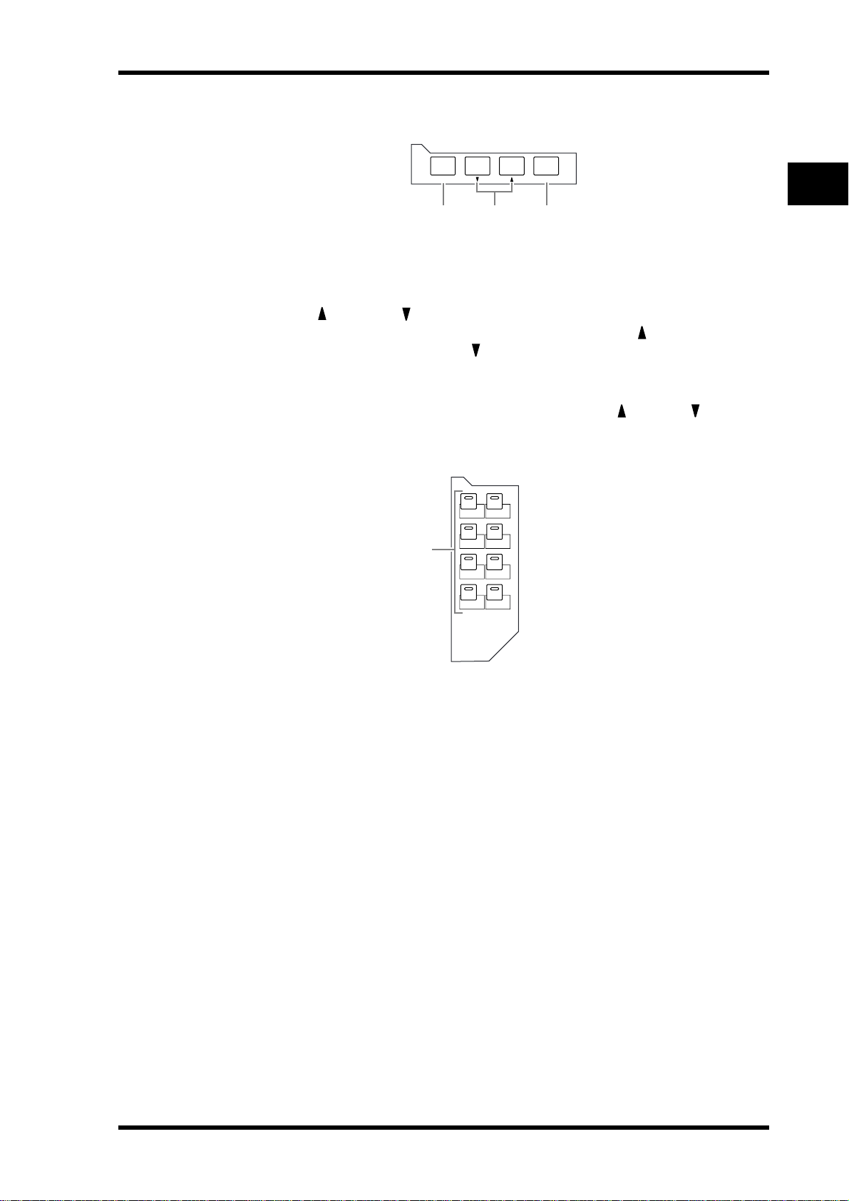
A [STORE] button
This button enables you to store the current mix settings. (See page 165 for more information on Scene Memories.)
B Scene Up [ ] / Down [ ] buttons
These buttons select a Scene to store or recall. Pressing the Scene Up [ ] button increments
the selection; pressing the Scene Down [ ] button decrements the selection. Holding down
either key increments or decrements the selection continuously.
C [RECALL] button
This button recalls the Scene memory selected by the Scene Up [ ] / Down [ ] buttons.
USER DEFINED KEYS Section
USER DEFINED
KEYS
12
34
1
56
2
Control Surface & Rear Panel
78
A [1]–[8] buttons
You can assign any of the 167 functions to these User Defined buttons.
01V96 Version 2—Owner’s Manual
Page 22

22 Chapter 2—Control Surface & Rear Panel
Data Entry Section
DEC INC
4
3
1
2
ENTER
A Parameter wheel
This control adjusts the parameter values shown on the display. Turning it clockwise
increases the value; turning it counterclockwise decreases the value. This wheel also enables
you to scroll a displayed list and select a character for entry (see page 30).
B [ENTER] button
This button activates a selected (highlighted) button on the display, and confirms the edited
parameter values.
C [DEC] & [INC] buttons
These buttons increment or decrement a parameter value by one. Pressing the [INC] button increments the value; pressing the [DEC] button decrements the value. Holding down
either key increments or decrements the value continuously.
D Left, Right, Up, Down ([ ]/[ ]/[ ]/[ ]) cursor buttons
These buttons move the cursor around the display pages, or select parameters and options.
Holding down a cursor button moves the cursor continuously in the corresponding direction.
SOLO Section
1
SOLO CLEAR
2
A [SOLO] indicator
This indicator flashes when single or multiple channels are soloed.
B [CLEAR] button
This button “unsolos” all soloed Channels.
01V96 Version 2—Owner’s Manual
Page 23
Rear Panel
Rear Panel 23
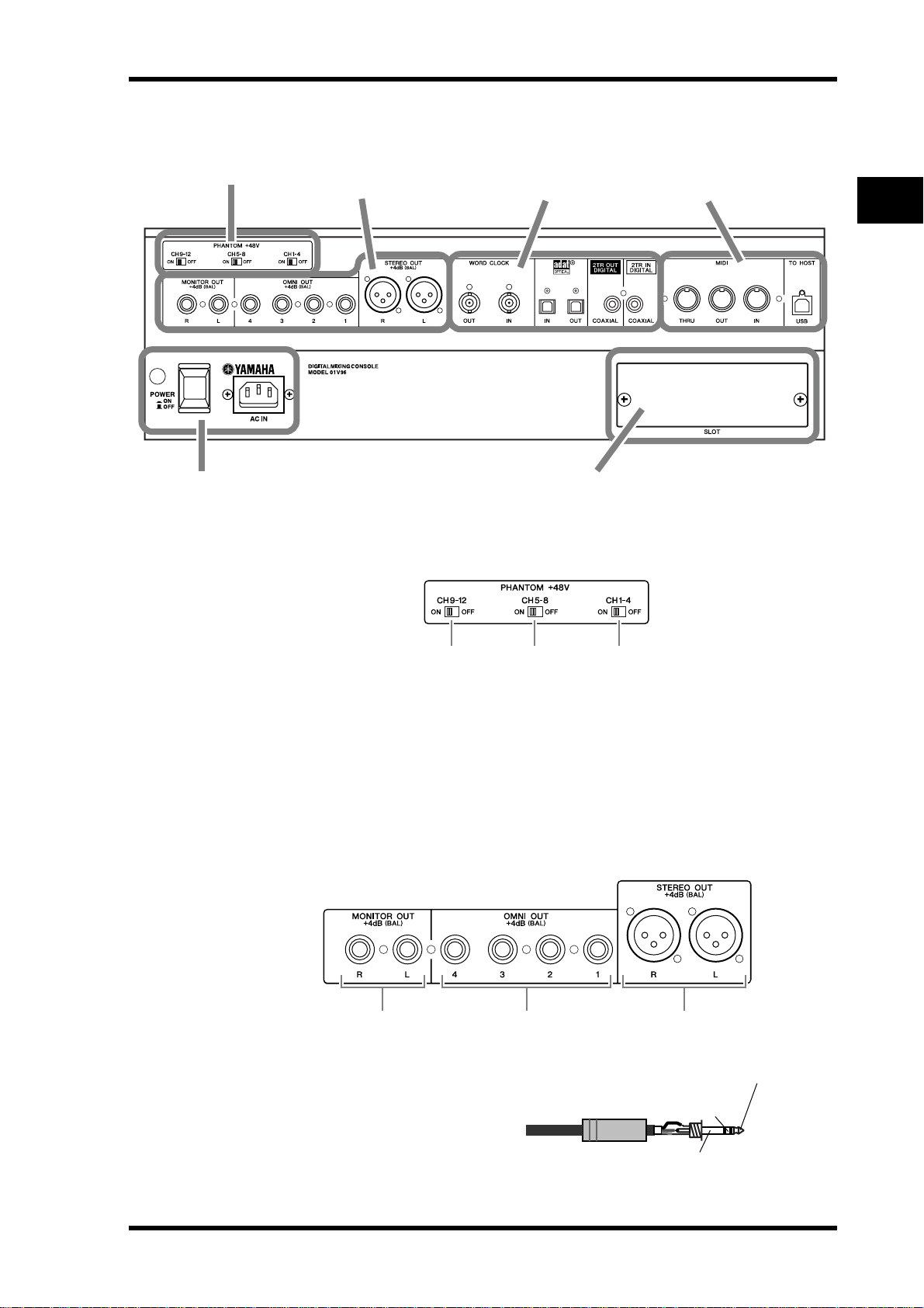
PHANTOM +48V (p. 23)
Power Section (p. 25)
PHANTOM +48V
AD Output Section
(p. 23)
Digital I/O Section
(p. 24)
SLOT Section (p. 25)
MIDI/Control Section
(p. 25)
2
Control Surface & Rear Panel
3 2 1
A CH1–4 ON/OFF switch
B CH5–8 ON/OFF
switch
C CH9–12 ON/OFF switch
Each of these switches turns on or off the +48V phantom power feed to four corresponding
inputs. When the switches are on, +48V phantom power is supplied to the INPUT A connectors.
AD Output Section
321
A MONITOR OUT connectors L/R
These balanced TRS phone-type connectors output monitoring signals or
2TR IN signals. The nominal signal
level is +4 dB.
You can select signals using the Monitor Source selector.
1/4" TRS phone plug
Ring
(cold)
Sleeve (ground)
Tip (hot)
01V96 Version 2—Owner’s Manual
Page 24
24 Chapter 2—Control Surface & Rear Panel
B OMNI OUT connectors 1–4
These balanced TRS phone-type connectors output any Bus signals or
channel Direct Out signals. The nominal signal level is +4 dB.
C STEREO OUT connectors L/R
These balanced XLR-3-32-type connectors output the Stereo Out signals.
The nominal signal level is +4 dB.
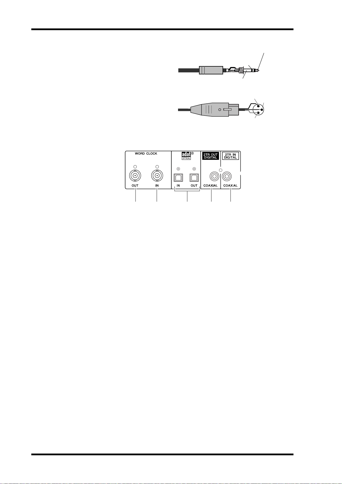
Digital I/O Section
1/4" TRS phone plug
Female XLR plug
421 53
Tip (hot)
Ring
(cold)
Sleeve (ground)
2 (hot)
3 (cold)
1 (ground)
A WORD CLOCK OUT connector
This BNC connector outputs a wordclock signal from the 01V96 to a connected external
device.
B WORD CLOCK IN connector
This BNC connector inputs a wordclock signal from a connected external device to the
01V96.
C ADAT IN/OUT connectors
These optical TOSLINK connectors input and output ADAT digital audio signals.
D 2TR OUT DIGITAL COAXIAL
This RCA phono connector outputs consumer format (IEC-60958) digital audio. The connector is typically used to connect the digital stereo input (consumer format) of a DAT
recorder, MD recorder, or CD recorder.
E 2TR IN DIGITAL COAXIAL
This RCA phono connector accepts consumer format (IEC-60958) digital audio. The connector is typically used to connect the digital stereo output (consumer format) of a DAT
recorder, MD recorder, or CD recorder.
01V96 Version 2—Owner’s Manual
Page 25
Rear Panel 25
MIDI/Control Section
21
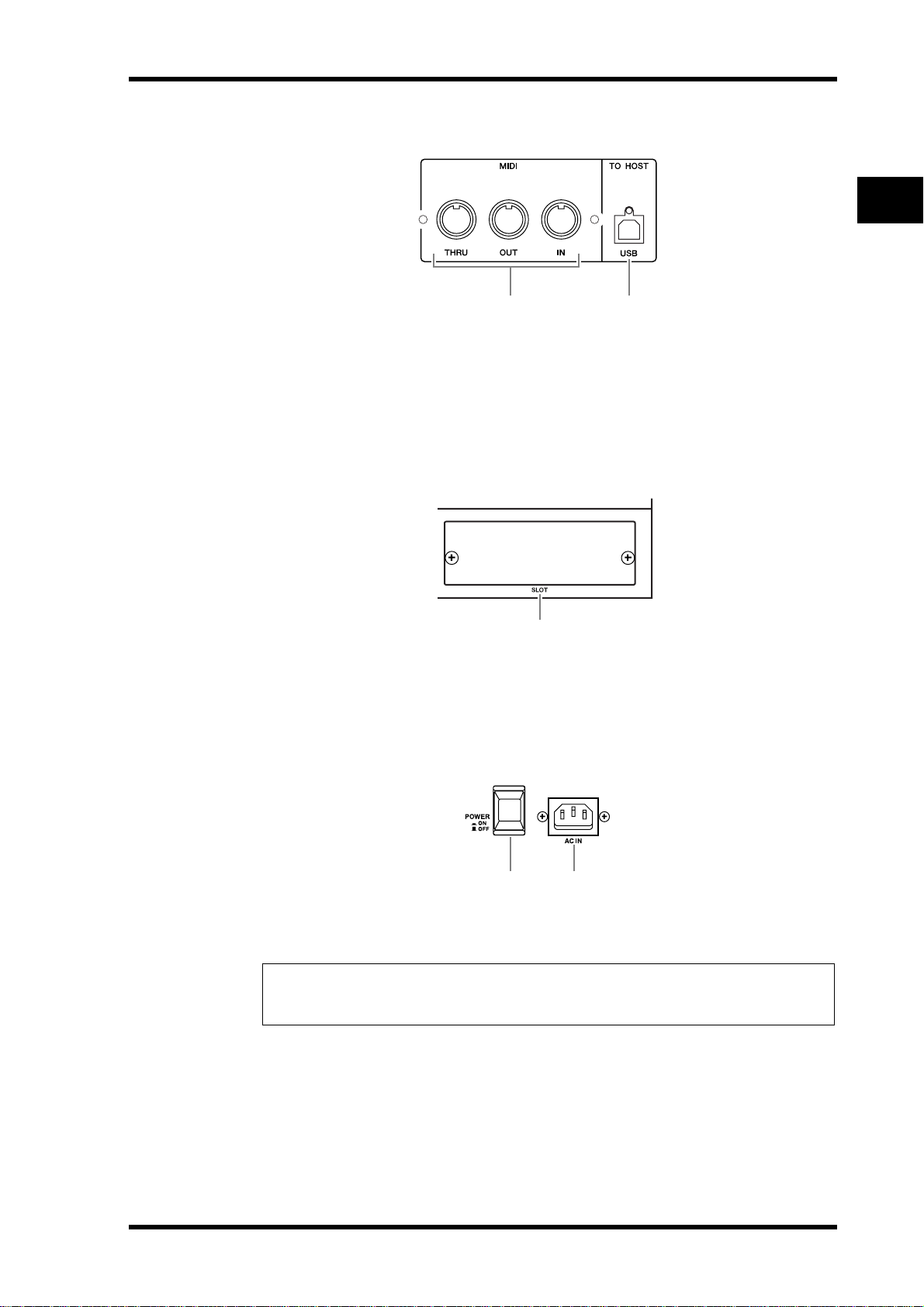
A MIDI IN/THRU/OUT ports
These standard MIDI IN, OUT and THRU ports enable you to connect the 01V96 to other
MIDI equipment.
B TO HOST USB port
This USB port enables you to connect a computer equipped with a USB port.
SLOT Section
2
Control Surface & Rear Panel
1
A SLOT
You can insert optional mini-YGDAI cards into this slot. (See page 26 for information on
installing these cards.)
Power Section
21
A POWER ON/OFF switch
This switch turns the power to the 01V96 on or off.
Note: To prevent loud clicks and thumps in your speakers, turn on your audio equipment in
the following order (reverse this order when turning the equipment off )—sound sources, multitrack and master recorders, 01V96, monitoring power amplifiers.
B AC IN connector
This connector enables you to connect the 01V96 to an AC outlet via the supplied power
cord.
01V96 Version 2—Owner’s Manual
Page 26
26 Chapter 2—Control Surface & Rear Panel
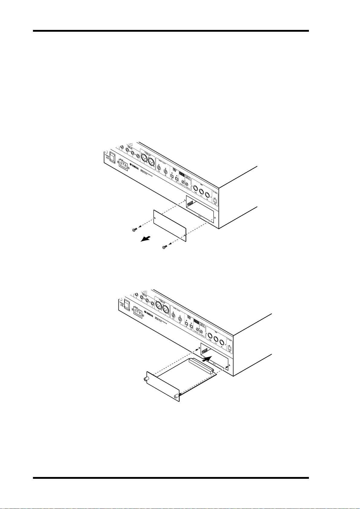
Installing an Optional Card
Visit the following Yamaha Pro Audio web site to ensure that the card you are installing is
supported by the 01V96.
<http://www.yamahaproaudio.com/>.
Follow the steps below to install an optional mini-YGDAI card.
1 Make sure that the power to the 01V96 is turned off.
2 Undo the two fixing screws and remove the slot cover, as shown below.
Keep the cover and fixing screws in a safe place for future use.
3 Insert the card between the guide rails and slide it all the way into the slot,
as shown below.
You may have to push firmly to fully insert the card into the internal connector.
4 Secure the card using the attached thumbscrews.
Tighten the screws firmly to secure the card. Otherwise, the card may not be grounded correctly.
01V96 Version 2—Owner’s Manual
Page 27
3 Operating Basics
This chapter describes basic operations on the 01V96, including how to use the display and
operate the controls on the top panel.
Operating Basics 27
About the Display
The top panel display indicates various parameters that you must set before you can operate
the 01V96. The display indicates the following items:
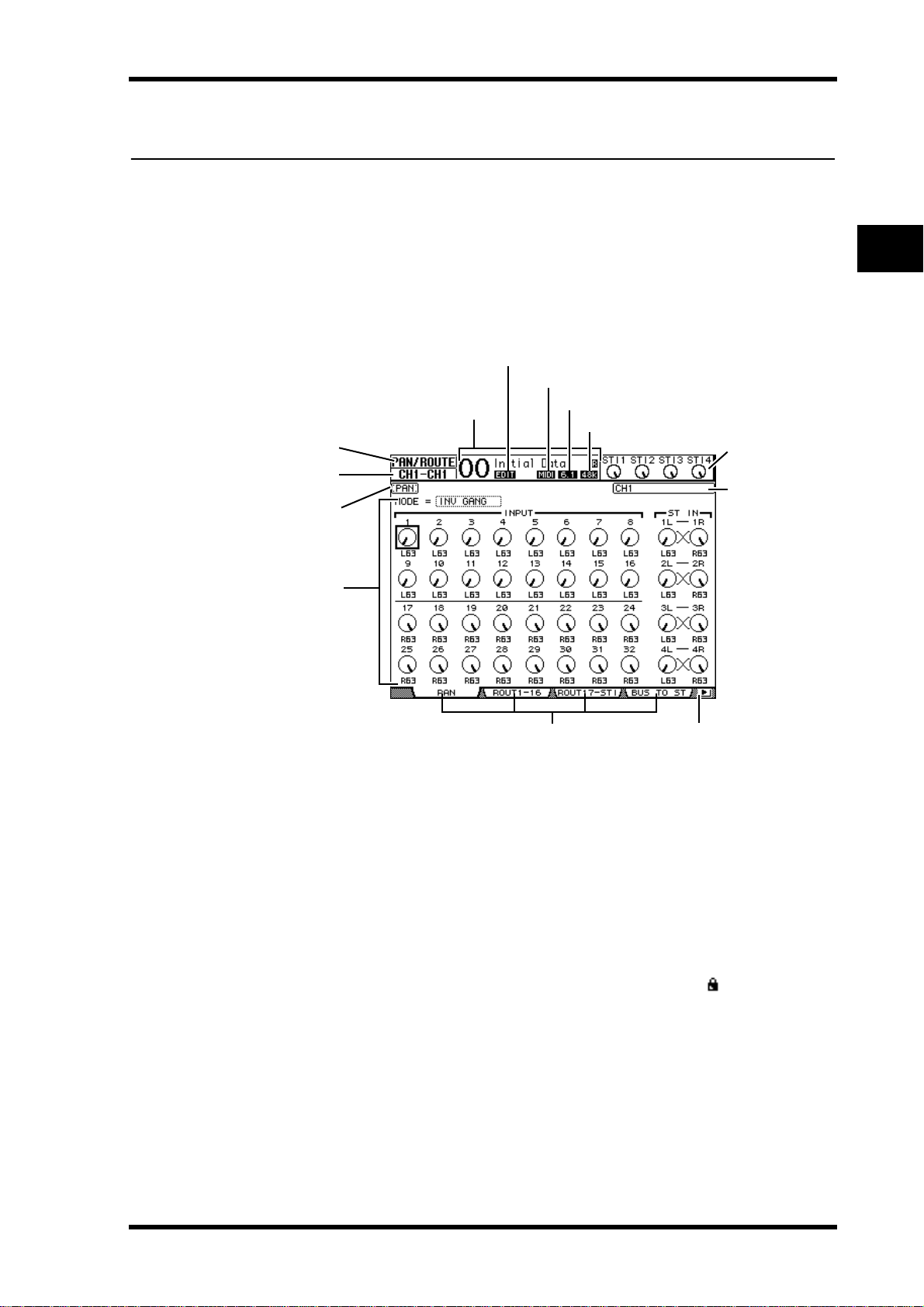
1Selected
DISPLAY
2Selected
channel
9Page title
KPage area
3Current Scene
3
Operating Basics
4EDIT indicator
5MIDI indicator
6Surround mode indicator
7Sampling rate indicator
8ST IN channel
levels
JChannel name
MTab Scroll arrowsLPage tabs
A Selected DISPLAY
This section indicates the currently-selected display page group.
B Selected channel
This section indicates the Input or Output Channel currently selected by its corresponding [SEL] button. The first four characters are the Channel ID (e.g., CH1–CH32,
BUS1–BUS8, AUX1–AUX8, ST-L, ST-R). The second four characters are the channel’s
Short name. You can edit the channel’s Short name if you desire (see page 229).
C Current Scene
This section indicates the number and title of the currently-selected Scene memory (see
page 166). If the selected Scene is write-protected, a padlock icon ( ) appears.
D EDIT indicator
This indicator appears when the current mix settings no longer match those of the Scene
that was most-currently recalled.
E MIDI indicator
This indicator appears when the 01V96 is receiving MIDI data via the MIDI IN port,
USB port, or an installed MY8-mLAN card.
F Surround mode indicator
This indicator identifies the currently-selected Surround mode (ST=stereo, 3-1, 5.1, or
6.1) (see page 135).
01V96 Version 2—Owner’s Manual
Page 28

28 Chapter 3—Operating Basics
G Sampling rate indicator
This indicator identifies the 01V96’s current sampling rate: 44.1 kHz (44k), 48 kHz
(48k), 88.2 kHz (88k), or 96 kHz (96k).
H ST IN channel levels
These level controls indicate the level of ST IN channels 1–4.
I Page title
This section indicates the title of the current page.
J Channel name
On certain pages, this area displays the Long name of the currently-selected channel.
K Page area
This page area displays various page contents.
L Page tabs
These tabs enable you to select a display page.
M Tab Scroll arrows
These arrows indicate that more pages are available.
Selecting Display Pages
To select a display page:
1 Press the corresponding button on the top panel to select the desired page
group.
Display pages are grouped by function. To select a page group, press the desired button in
the DISPLAY ACCESS section.
2You can select pages that have currently-displayed tabs by pressing the
[F1]–[F4] buttons.
If the selected display page group contains multiple pages, press the [F1]–[F4] buttons
below the corresponding tab to select a specific page.
3To select a page for which a tab is not currently displayed, press either the
Left or Right [ ]/[ ] Tab Scroll button (depending on where the page is
located) to display the page tab, then press the corresponding [F1]–[F4] button.
If display page groups contain more than four pages, either the left or right arrow appears.
To display the currently-hidden tabs, press the Right or Left [ ]/[ ] Tab Scroll button.
You can also select a page from a page group as follows:
• Selecting the next page in a page group:
Press the button you selected in Step 1 repeatedly. This enables you to select a page that has
a hidden tab.
•To select the previous page in a page group:
Press and hold down the button you selected in Step 1. The screen steps back through the
pages one by one. Release the button when the desired page is displayed. This enables you
to select a page that has a hidden tab.
•To select the first page in the group:
Double-click the button you selected in Step 1.
01V96 Version 2—Owner’s Manual
Page 29
4 Press the cursor buttons to move the cursor (a bold frame) to a button,
parameter box, rotary control, or fader so that you can change the value.
Tip: The 01V96 remembers the current page and parameter when you select a new page group.
If you return to the previous page group, the 01V96 displays the correct page, with the same
parameter selected. You can also select a page by using the controls or buttons on the top panel
(see page 230).
Display Interface
This section describes how to use the display interface.
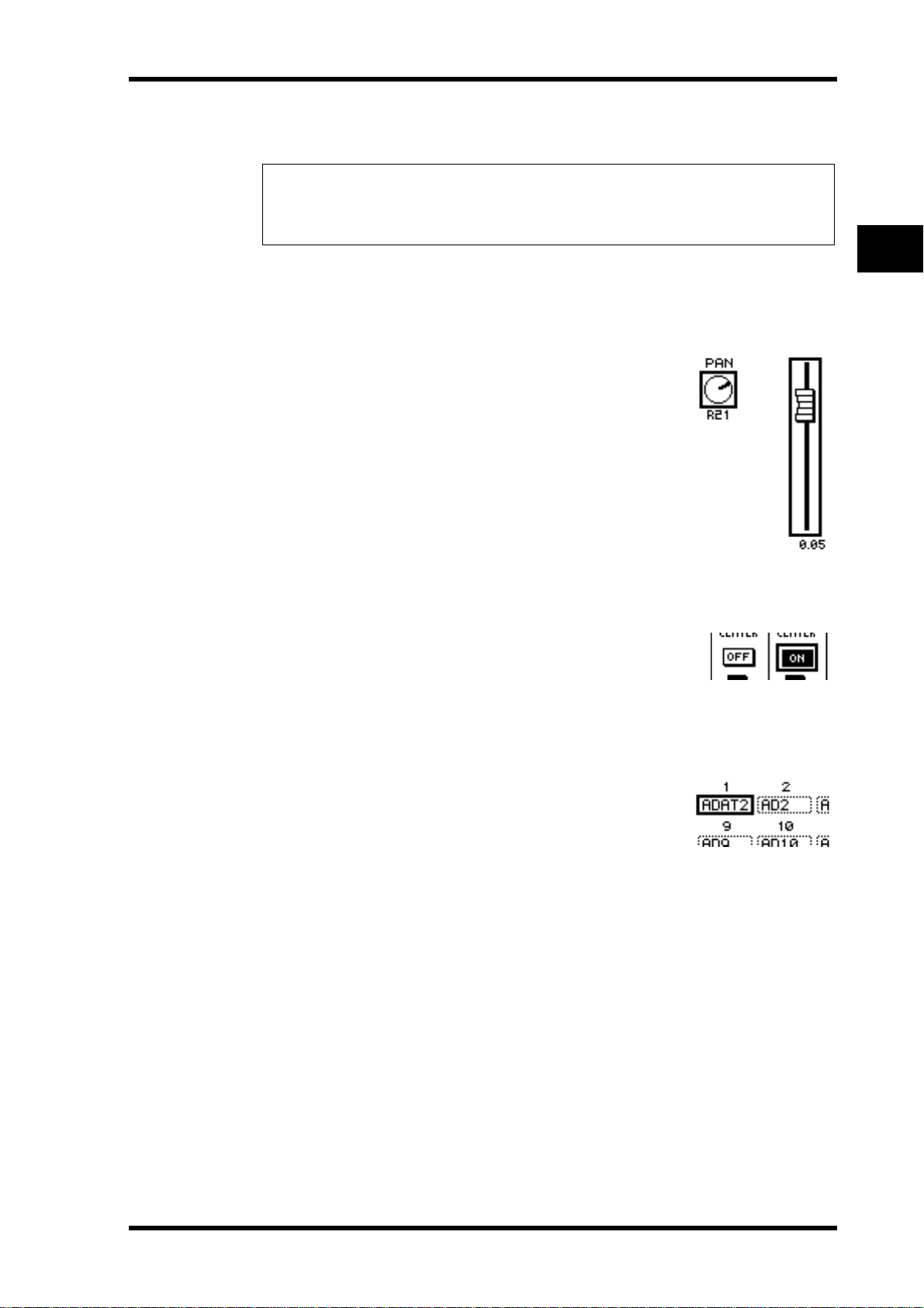
Rotary Controls & Faders
The rotary controls and faders enable you to adjust the continuously variable parameter values, including Input Channel levels and effects parameters. Press the cursor buttons to move the
cursor to a rotary control or fader you want to adjust, then
rotate the Parameter wheel or press the [INC]/[DEC] buttons
to modify the value.
Display Interface 29
3
Operating Basics
Buttons
The buttons enable you to turn certain functions on
(enabled) or off (disabled). Move the cursor to the appropriate button, then press the [ENTER] button to turn the function on (highlighted) or off. The buttons also enable you to
select one of two options or to execute certain functions.
Parameter Boxes
The parameter boxes enable you to select one of multiple
options. Press the cursor buttons to move the cursor to a
parameter box, then rotate the Parameter wheel or press the
[INC]/[DEC] buttons to select the setting.
You may need to press the [ENTER] button to confirm a
change in certain parameter boxes. If you edit a value in this
type of parameter box, the value flashes. Press the [ENTER]
button to confirm the change, and the flashing stops. If you
move the cursor to other parameters while the edited value is
flashing, the edit is cancelled.
01V96 Version 2—Owner’s Manual
Page 30
30 Chapter 3—Operating Basics
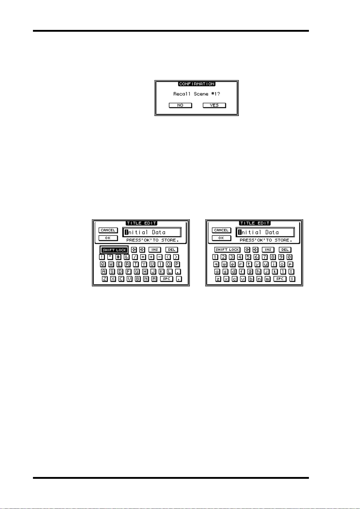
Confirmation Messages
For certain functions, the 01V96 prompts you for confirmation before executing the functions, as shown here.
Move the cursor to YES and press [ENTER] to execute the function, or move the cursor to
NO and press [ENTER] to cancel.
If you take no action for awhile, the confirmation window closes automatically and the
function is not executed.
Title Edit Window
The Title Edit window enables you to enter titles for Scene and library memories. You can
enter 4, 12, or 16 characters, depending on the item.
The figure on the left shows uppercase characters and various punctuation marks. The figure on the right shows lowercase characters and numbers.
Use the cursor buttons to select characters, and press the [ENTER] button to enter them
into the title. The cursor moves to the right automatically as each character is entered. Use
the Parameter wheel to move the cursor within the title.
Use the SHIFT LOCK button to select uppercase or lowercase characters, and use the SPC
button to enter a space.
To insert a space at the cursor position and move subsequent characters to the right, move
the cursor to the INS button and press [ENTER].
To delete the character at the cursor position and move subsequent characters to the left,
move the cursor to the DEL button and press [ENTER].
When you have finished, move the cursor to the OK button, then press [ENTER] to confirm
the title. To cancel the title entry, move the cursor to the CANCEL button, then press
[ENTER].
01V96 Version 2—Owner’s Manual
Page 31

Selecting Layers
Input Channels and Output Channels (Bus Outs & Aux Outs) are arranged into layers, as
illustrated below. There are four layers altogether.
Selecting Layers 31
3
Operating Basics
Input Channel Layer 1–16
Input Channel Layer 17–32
Master Layer
Remote Layer
The currently-selected layer determines the function of
the channel strip, [SEL] buttons, [SOLO] buttons,
LAYER
[ON] buttons, and faders. Use the LAYER buttons to
select a layer you wish to edit using the channel strip
1-16 17-32 MASTER REMOTE
controls.
The following table shows the layers that you can access using the LAYER buttons, and the
parameters you can control using the channel strips on each layer.
LAYER buttons Layers
[1–16] button
[17–32] button
[REMOTE] button
[MASTER] button
Input Channel Layer 1–16 Input Channels 1–16
Input Channel Layer 17–32 Input Channels 17–32
Remote Layer
Master Layer
Operation depends on the selected
target (see page 189).
Aux Send masters
1–8
Channel Strips
1–8 9–16
Bus Out masters
1–8
Tip:
• The function of each channel strip fader depends on the currently-selected Fader mode (see
page 33).
• The STEREO [SEL] button, [ON] button, and [STEREO] fader always control the Stereo
Out signal, regardless of the Layer settings.
• The ST IN [SEL] buttons, [SOLO] buttons, [ON] buttons, and level control knobs always
adjust the ST IN channels selected via the [ST IN] button regardless of the Layer settings.
01V96 Version 2—Owner’s Manual
Page 32

32 Chapter 3—Operating Basics
Selecting Channels
To select a channel on the 01V96, press the corresponding [SEL]
SELECTED CHANNEL
button. To adjust the Pan and EQ settings, use the rotary controls
in the SELECTED CHANNEL section. To select a channel on pages
PAN
that cover multiple channels, press the corresponding [SEL] button.
EQUALIZER
1 Press the corresponding LAYER button to select a layer
that includes the desired channel (see page 31).
Q
To select ST IN channels, press the ST IN [ST IN] button.
2 Use the corresponding [SEL] button to select the desired
channel.
The channel is selected and the [SEL] button indicator lights up.
FREQUENCY
HIGH-MID
LOW-MID
The Channel’s ID and Short name appear in the upper-left corner
of the display. If the currently-displayed page contains a relevant
GAIN
channel parameter, the cursor moves to that parameter automatically. If the currently-displayed page contains no such parameter, a
page that does contain such a parameter is selected automatically.
Tip: For paired Input or Output Channels, the channel for which you pressed the [SEL] button
is selected, and its indicator lights up. The [SEL] button indicator of the paired partner flashes.
3To select the Stereo Out, press the STEREO [SEL] button.
Repeatedly pressing the STEREO [SEL] button toggles between the Stereo Out left and Stereo Out right channels.
If the currently-displayed page contains a relevant Stereo Out parameter, the cursor moves
to that parameter automatically. If the currently-displayed page contains no such parameter, a page that does contain such a parameter is selected automatically.
HIGH
LOW
01V96 Version 2—Owner’s Manual
Page 33

Selecting Fader Modes
The function of channel faders (1–16) depends on the selected Layer and Fader mode.
1 Select a layer that includes the desired channel (see page 31).
Selecting Fader Modes 33
2 Press the FADER MODE buttons to select a Fader
FADER MODE
mode.
The button indicators identify the following Fader modes:
AUX 1 AUX 2 AUX 3 AUX 4
•When the [HOME] button indicator lights up:
You can use channel faders to control Input Channels
and ST IN Channel levels or Output Channels (Aux
Out 1–8, Bus Out 1–8) master levels.
HOME (METER)
•When one of the [AUX1]–[AUX8] button indicators
light up:
You can use channel faders to control the corresponding Aux Send level.
The following table shows the channel fader functions for each Layer and Fader mode.
LAYER buttons Fader Mode
[1–16] button
[17–32] button
[REMOTE] button
[MASTER] button
[HOME] button
[AUX1]–[AUX8] buttons
[HOME] button
[AUX1]–[AUX8] buttons
[HOME] button
[AUX1]–[AUX8] buttons
[HOME] button
[AUX1]–[AUX8] buttons
Input Channel 1–16 level
Input Channel 1–16 Aux Send level
Input Channel 17–32 level
Input Channel 17–32 Aux Send level
Operation depends on the selected target (see
page 189).
Aux Send master 1–8
output level
No operation
Channel Strip Fader
1–8 9–16
Bus Out master1–8
output level
3
Operating Basics
AUX 8AUX 7AUX 6AUX 5
Note: You cannot select the [AUX1]–[AUX8] buttons while the Master layer is selected. If you
switch to the Master layer while one of the [AUX1]–[AUX8] button indicators is lit, the indicator automatically turns off and the [HOME] button indicator lights up.
01V96 Version 2—Owner’s Manual
Page 34

34 Chapter 3—Operating Basics
Metering
This section describes how to check Input and Output Channel levels using the Meter
pages.
1 Press the FADER MODE [HOME] button repeatedly until the Meter | Position
page appears.
This page enables you to set the metering position for Input and Output Channels.
1
2
A INPUT section
This section enables you to select the metering position for Input Channel and ST IN
Channel signals.
B OUTPUT section
This section enables you to select the metering position for Output Channel (Aux Out
1–8, Bus Out 1–8, Stereo Out) signals.
2 Move the cursor to the desired parameter button in the INPUT or OUTPUT
section, then press [ENTER].
You can select one of the following three positions in each section.
• PRE EQ..........................Immediately before EQ.
• PRE FADER..................Immediately before the fader.
• POST FADER...............Immediately after the fader.
3 Press the FADER MODE [HOME] button repeatedly until the page listed
below that contains the desired channels appears.
- CH1-32 page
This page displays the Input Channel 1–32 levels respectively.
01V96 Version 2—Owner’s Manual
Page 35

Metering 35
- ST IN page
This page displays the left and right ST IN Channel 1–4 levels separately.
-Master page
This section displays the Output Channel (Aux Out 1–8, Bus Out 1–8, Stereo Out) levels
altogether.
3
Operating Basics
-Effect page
This page displays the internal effects processor 1–4 input and output levels altogether.
01V96 Version 2—Owner’s Manual
Page 36

36 Chapter 3—Operating Basics
-Stereo page
This page displays the Stereo Out output level.
If you selected the CH1-32 page or the Master page, use the MASTER MODE parameter to
select one of the following three metering signal types:
• GATE GR....................... The amount of gain reduction for the gate (only for CH1-32)
• COMP GR.....................The amount of gain reduction for the compressor
• LEVEL ........................... Input Channel input level, or Output Channel output level
Tip: These pages also allow you to change the metering position using the POSITION parameter. This parameter setting operates in unison with the Meter | Position page setting.
4To activate the Peak Hold function, move the cursor to the PEAK HOLD but-
ton, then press [ENTER].
The PEAK HOLD button turns on, and the peak level is held on the meters on the page. To
cancel the Peak Hold function, turn the PEAK HOLD button off.
01V96 Version 2—Owner’s Manual
Page 37

4 Connections and Setup
This chapter explains how to connect and set up your 01V96.
Connections
The following section explains three typical ways to connect the 01V96 to external equipment, although there are numerous others.
■ Configuring an analog 24-channel mixing system
Synthesizer Synthesizer
MUSIC
SYNTHESIZER
PRODUCTION
Sequencer
Sampling
Integrated
Real-timeExternalControl
Surface
Modular
SynthesisPlug-in
SONG SCENE
REC
System
SONG SCENE
REC
MUSIC
Connections and Setup 37
SYNTHESIZER
PRODUCTION
Sequencer
Sampling
Integrated
Real-timeExternalControl
Surface
Modular
SynthesisPlug-in
System
4
Connections and Setup
Effects processor
88
Guitar
MY8-AD96
Master recorder
etc.
INPUT connector
OMNI OUT connector
INPUT connector
INPUT connector
SLOT
ABABABABABABABABABABABA
INPUT
(BAL)
INSERT
OUTIN
(UNBAL)
/
O INSERT I/O INSERT I/O INSERT I/O INSERT I/O INSERT I/O INSERT I/O INSERT I/O INSERT I/O INSERT I/O INSERT I/OINSERT I/O
INSERT I
PAD
-16 -60
-16 -60
-16 -60
-16 -60
GAIN
GAIN
GAIN
GAIN
PEAK
PEAK
PEAK
PEAK
SIGNAL
SIGNAL
SIGNAL
SIGNAL
DISPLAY ACCESS
DIO/SETUP
UTILITYMIDISCENE
PAN/
PAIR/
/ INSERT/
PATCH
ROUTING
GROUP
DELAY
EQ EFFECT VIEW
DYNAMICS
FADER MODE
AUX 1
AUX 2 AUX 3 AUX 4
AUX 8AUX 7AUX 6AUX 5
HOME (METER)
LAYER
1-16 17-32 MASTER REMOTE
SEL SEL SEL SEL SEL SEL SEL SEL SEL SEL SEL SEL SEL SEL SEL SEL SEL SELSEL
SOLO SOLO
SOLOONSOLOONSOLOONSOLOONSOLOONSOLOONSOLOONSOLOONSOLOONSOLOONSOLOONSOLOONSOLOONSOLOONSOLOONSOLO
ON ON
123456
+10
+10
+10
+10
+10
0
0
0
0
5
5
5
5
5
5
5
5
5
0
0
0
0
0
10
10
10
10
5
5
5
5
5
15
15
15
15
20
20
20
20
10
10
10
10
10
15
15
15 15
15
30
303030
20
20
20
20
20
40
40
40
40
50
50
50
50
30
30
30
30
30
60
60
60
60
40
40
40
40
40
70
70
70
70
50
50
50
50
123456
AUX 1 AUX 2 AUX 3 AUX 4 AUX 5 AUX 6 AUX 7 AUX 8 BUS 1 BUS 2 BUS 3 BUS 4 BUS 5 BUS 6 BUS 7 BUS 8
-16 -60
+10
0
5
5
0
10
5
15
20
10
15
30
20
40
50
30
60
40
70
GAIN
PEAK
SIGNAL
+10
0
5
5
0
10
5
15
20
10
15
30
20
40
50
30
60
40
70
-16 -60
-16 -60
GAIN
GAIN
PEAK
PEAK
SIGNAL
SIGNAL
891011 12
7
+10
+10
0
0
5
5
5
5
0
0
10
10
5
5
15
15
20
20
10
10
15
15
30
30
20
20
40
40
50
50
30
30
60
60
40
40
70
70
50
50505050
891011 12
7
-16 -60
GAIN
PEAK
SIGNAL
+10
0
0
5
5
5
0
10
10
5
15
15
20
20
10
15
30
30
20
40
40
50
50
30
60
60
40
70
70
50
121110987643215
B
20dB
20dB
20dB20dB20dB20dB20dB20dB20dB20dB20dB20dB
-16 -60
-16 -60
-16 -60
-16 -60
GAIN
GAIN
GAIN
GAIN
PEAK
PEAK
PEAK
SIGNAL
SIGNAL
SIGNAL
SCENE MEMORY
STORE
SELECTED CHANNEL
OVER
0
-3
-6
PAN
-9
-12
-15
EQUALIZER
-18
-24
-30
-36
HIGH
Q
-48
STEREO
HIGH-MID
FREQUENCY
LOW-MID
LOW
GAIN
13 14 15 16
+10
+10
+10
+10
+10
0
0
0
0
5
5
5
5
5
5
5
5
0
0
0
0
10
10
10
10
5
5
5
5
15
15
15
15
20
20
20
20
10
10
10
10
10
15
15
15
15
15
30
30
30
30
20
20
20
20
40
40
40
40
50
50
50
50
30
30
30
30
60
60
60
60
40
40
40
40
70
70
70
70
50
50
50
50
13 14 15 16
PEAK
SIGNAL
ENTER
5
0
5
20
30
40
50
14
+4
GAIN
+4
GAIN
PEAK
13 14 15 16
SIGNAL
DEC INC
+10
0
5
5
0
10
5
15
20
10
15
20
40
50
30
60
40
70
50
32313029282726252423222120191817
CH9-12CH5-8CH1-4
PHANTOM +48V
1513
L
16
R
IN OUT
2TR
2TR IN connector
-10dBV (UNBAL)
PHONES
/
16
MONITOR
CH15
2TR IN
2TR IN
0100
-26
-26
10
+4
GAIN
LEVEL
LEVEL
PHONES
MONITOR
OUT
-26
-26
+4
GAIN
2TR OUT connector
PEAK
SIGNAL
SOLO CLEAR
RECALL
MONITOR OUT
ST IN
connectors
ONON
ST IN 1 ST IN 2
00
55
USER DEFINED
KEYS
1010
1515
12
2020
34
303030
4040
5050
6060
7070
STEREO
PHONES jack
56
78
VOL VOL
Monitoring system
In this system, the 01V96, with an optional AD card (MY8-AD, MY8-AD96, etc.) installed
in the slot, is used as a keyboard mixer or sound re-enforcement mixer. Up to 24 analog
channels, including Inputs 1–16 and slot channels, are available for mixing.
Tip: You can adjust the gain of the AD card channels by setting the DIP switches on the card.
For more information, see your AD card documentation.
01V96 Version 2—Owner’s Manual
Page 38

38 Chapter 4—Connections and Setup
■ Configuring a recording system with a hard disk recorder
Effects processor
88
Synthesizer
REC
INPUT connector
OMNI OUT connector
MUSIC
SYNTHESIZER
PRODUCTION
Sequencer
Sampling
Integrated
Real-timeExternalControl
Surface
Modular
SynthesisPlug-in
SONG SCENE
System
INPUT connector
INPUT connector
HDR (Hard Disk Recorder)
MIDI OUT
WORD CLOCK OUT
INOUT INOUT
MY8-AT
etc.
SLOT
ABABABABABABABABABABABA
INPUT
(BAL)
INSERT
OUTIN
(UNBAL)
/
O INSERT I/O INSERT I/O INSERT I/O INSERT I/O INSERT I/O INSERT I/O INSERT I/O INSERT I/O INSERT I/O INSERT I/O INSERT I/O
INSERT I
PAD
-16 -60
-16 -60
GAIN
GAIN
PEAK
PEAK
SIGNAL
SIGNAL
DISPLAY ACCESS
DIO/SETUP
PAN/
/ INSERT/
ROUTING
GROUP
DELAY
EQ EFFECT VIEW
DYNAMICS
FADER MODE
AUX 1
AUX 2 AUX 3 AUX 4
HOME (METER)
LAYER
1-16 17-32 MASTER REMOTE
SEL SEL SEL SEL SEL SEL SEL SEL SEL SEL SEL SEL SEL SEL SEL SEL SEL SELSEL
SOLO SOLO
ON ON
123456
+10
+10
0
5
5
5
0
0
10
5
5
15
20
10
10
15 15
15
20
20
40
50
30
30
60
40
40
70
50
50
123456
AUX 1 AUX 2 AUX 3 AUX 4 AUX 5 AUX 6 AUX 7 AUX 8 BUS 1 BUS 2 BUS 3 BUS 4 BUS 5 BUS 6 BUS 7 BUS 8
ADAT IN
-16 -60
-16 -60
-16 -60
-16 -60
GAIN
GAIN
GAIN
GAIN
PEAK
PEAK
PEAK
PEAK
SIGNAL
SIGNAL
SIGNAL
SIGNAL
UTILITYMIDISCENE
PAIR/
PATCH
AUX 8AUX 7AUX 6AUX 5
SOLOONSOLOONSOLOONSOLOONSOLOONSOLOONSOLOONSOLOONSOLOONSOLOONSOLOONSOLOONSOLOONSOLOONSOLOONSOLO
+10
0
5
5
0
10
5
15
20
10
20
40
50
30
60
40
70
50
7
0
5
10
15
20
303030
40
50
60
70
5
5
5
5
5
5
5
5
5
0
0
0
0
0
10
10
10
10
5
5
5
5
5
15
15
15
15
20
20
20
20
10
10
10
10
10
15
15
15
15
15
30
30
30
30
20
20
20
20
20
40
40
40
40
50
50
50
50
30
30
30
30
30
60
60
60
60
40
40
40
40
40
70
70
70
70
50
50505050
+10
+10
+10
+10
+10
0
0
0
0
7
MIDI IN
ADAT OUT
-16 -60
-16 -60
-16 -60
GAIN
GAIN
GAIN
PEAK
PEAK
PEAK
SIGNAL
SIGNAL
SIGNAL
891011 12
+10
+10
+10
0
0
0
5
5
5
5
5
5
0
0
0
10
10
10
5
5
5
15
15
15
20
20
20
10
10
10
15
15
15
30
30
30
20
20
20
40
40
40
50
50
50
30
30
30
60
60
60
40
40
40
70
70
70
50
50
50
891011 12
WORD CLOCK IN connector
121110987643215
B
20dB
20dB20dB20dB20dB20dB20dB20dB20dB20dB20dB
20dB
-16 -60
-16 -60
-16 -60
GAIN
GAIN
GAIN
PEAK
PEAK
PEAK
SIGNAL
SIGNAL
SIGNAL
SCENE MEMORY
STORE
SELECTED CHANNEL
OVER
0
-3
-6
PAN
DEC INC
-9
-12
-15
EQUALIZER
-18
-24
-30
-36
HIGH
Q
-48
STEREO
HIGH-MID
FREQUENCY
LOW-MID
ENTER
LOW
GAIN
13 14 15 16
+10
+10
+10
+10
0
0
0
0
5
5
5
5
5
5
5
5
0
0
0
0
10
10
10
10
5
5
5
5
15
15
15
15
20
20
20
20
10
10
10
10
15
15
15
15
30
30
30
30
20
20
20
20
40
40
40
40
50
50
50
50
30
30
30
30
60
60
60
60
40
40
40
40
70
70
70
70
50
50
50
50
13 14 15 16
14
-26
+4
GAIN
-26
+4
GAIN
PEAK
13 14 15 16
SIGNAL
+10
0
5
5
0
10
5
15
20
10
15
20
40
50
30
60
40
70
50
32313029282726252423222120191817
CH9-12CH5-8CH1-4
PHANTOM +48V
1513
L
16
R
IN OUT
2TR
-10dBV (UNBAL)
PHONES
/
16
MONITOR
CH15
2TR IN
2TR IN
0100
-26
10
+4
GAIN
LEVEL
LEVEL
PHONES
MONITOR
OUT
-26
+4
GAIN
PEAK
SIGNAL
SOLO CLEAR
RECALL
ST IN
ONON
ST IN 1 ST IN 2
00
55
USER DEFINED
KEYS
1010
1515
12
2020
34
303030
4040
56
5050
6060
7070
78
STEREO
MIDI OUT
MIDI IN
Computer
Master recorder
TO HOST USB port
2TR IN connector
2TR OUT connector
MONITOR OUT
connectors
VOL VOL
Monitoring system
PHONES jack
In this system, the 01V96 is one component in a system that includes a digital MTR, such
as a hard disk recorder, that is connected to the 01V96 via the ADAT IN and OUT connectors on the rear panel and via an optional I/O card (MY8-AT, MY16-AT, MY8-TD, etc.)
installed in the slot. This system will support track recording, overdubbing, track bouncing,
and mixdown. You can also control the hard disk recorder’s transport section by sending
MMC commands from the 01V96 to the recorder.
01V96 Version 2—Owner’s Manual
Page 39

Connections 39
■ Configuring a recording system that uses a DAW (Digital Audio
Workstation)
Computer
MIDI interface
MIDI IN
MIDI OUT
Audio interface
WORD CLOCK OUT
INOUT INOUT
4
Connections and Setup
Effects processor
88
Synthesizer
REC
MY-16AT
Master recorder
etc.
ADAT OUT
ADAT IN
-16 -60
-16 -60
-16 -60
-16 -60
GAIN
GAIN
GAIN
GAIN
PEAK
PEAK
PEAK
PEAK
SIGNAL
SIGNAL
SIGNAL
SIGNAL
UTILITYMIDISCENE
PAIR/
PATCH
GROUP
AUX 8AUX 7AUX 6AUX 5
SOLOONSOLOONSOLOONSOLOONSOLOONSOLOONSOLOONSOLOONSOLOONSOLOONSOLOONSOLOONSOLOONSOLOONSOLOONSOLO
+10
+10
+10
+10
0
0
0
0
0
5
5
5
5
5
5
10
15
20
40
50
60
70
5
5
5
0
0
0
0
10
10
10
10
5
5
5
5
15
15
15
15
20
20
20
20
10
10
10
10
15
15
15
30
30
303030
30
20
20
20
20
40
40
40
40
50
50
50
50
30
30
30
30
60
60
60
60
40
40
40
40
70
70
70
70
50
50
-16 -60
GAIN
GAIN
PEAK
PEAK
SIGNAL
SIGNAL
891011 12
7
+10
+10
0
0
5
5
5
5
0
0
10
10
5
5
15
15
20
20
10
10
15
15
30
30
20
20
40
40
50
50
30
30
60
60
40
40
70
70
50505050
891011 12
7
-16 -60
-16 -60
GAIN
GAIN
PEAK
PEAK
SIGNAL
SIGNAL
OVER
STEREO
+10
+10
+10
0
0
5
5
5
5
5
0
0
0
10
10
10
5
5
5
15
15
15
20
20
20
10
10
10
15
15
15
30
30
30
20
20
20
40
40
40
50
50
50
30
30
30
60
60
60
40
40
40
70
70
70
50
50
50
MIDI IN
WORD CLOCK IN connector
121110987643215
1513
14
16
B
CH15
2TR IN
20dB
20dB20dB20dB20dB20dB20dB20dB20dB20dB20dB
20dB
-26
+4
+4
GAIN
GAIN
-26
-16 -60
-16 -60
GAIN
PEAK
SIGNAL
SELECTED CHANNEL
0
-3
-6
-9
-12
-15
-18
-24
-30
-36
-48
FREQUENCY
+4
+4
-16 -60
GAIN
GAIN
GAIN
GAIN
PEAK
PEAK
PEAK
PEAK
13 14 15 16
SIGNAL
SIGNAL
SIGNAL
SIGNAL
SCENE MEMORY
STORE
RECALL
PAN
DEC INC
EQUALIZER
HIGH
Q
HIGH-MID
LOW-MID
ENTER
LOW
GAIN
13 14 15 16
+10
+10
+10
+10
+10
0
0
5
5
5
5
0
0
10
5
5
15
20
10
10
15
15
30
20
20
40
50
30
30
60
40
40
70
50
50
0
0
5
5
5
5
0
0
10
10
5
5
15
15
20
20
10
10
15
15
30
30
20
20
40
40
50
50
30
30
60
60
40
40
70
70
50
50
13 14 15 16
00
0
5
55
5
0
1010
10
5
1515
15
2020
20
10
15
303030
20
4040
40
5050
50
30
6060
60
40
7070
70
50
32313029282726252423222120191817
STEREO
TO HOST USB port
MIDI OUT
CH9-12CH5-8CH1-4
PHANTOM +48V
L
R
IN OUT
2TR
-10dBV (UNBAL)
PHONES
/
16
MONITOR
2TR IN
0100
-26
10
LEVEL
LEVEL
PHONES
MONITOR
OUT
-26
SOLO CLEAR
ST IN
ONON
ST IN 1 ST IN 2
USER DEFINED
KEYS
12
34
56
78
2TR IN connector
2TR OUT connector
MONITOR OUT
connectors
Monitoring system
PHONES jack
INPUT connector
OMNI OUT connector
MUSIC
SYNTHESIZER
PRODUCTION
Sequencer
Sampling
Integrated
Real-timeExternalControl
Surface
Modular
SynthesisPlug-in
SONG SCENE
System
INPUT connector
INPUT connector
SLOT
ABABABABABABABABABABABA
INPUT
(BAL)
INSERT
OUTIN
(UNBAL)
/
O INSERT I/O INSERT I/O INSERT I/O INSERT I/O INSERT I/O INSERT I/O INSERT I/O INSERT I/O INSERT I/O INSERT I/OINSERT I/O
INSERT I
PAD
-16 -60
-16 -60
GAIN
PEAK
SIGNAL
DISPLAY ACCESS
DIO/SETUP
PAN/
/ INSERT/
ROUTING
DELAY
EQ EFFECT VIEW
DYNAMICS
FADER MODE
AUX 1
AUX 2 AUX 3 AUX 4
HOME (METER)
LAYER
1-16 17-32 MASTER REMOTE
SEL SEL SEL SEL SEL SEL SEL SEL SEL SEL SEL SEL SEL SEL SEL SEL SEL SELSEL
SOLO SOLO
ON ON
123456
+10
+10
0
5
5
5
0
0
10
5
5
15
20
10
10
15
15 15
20
20
40
50
30
30
60
40
40
70
50
50
123456
AUX 1 AUX 2 AUX 3 AUX 4 AUX 5 AUX 6 AUX 7 AUX 8 BUS 1 BUS 2 BUS 3 BUS 4 BUS 5 BUS 6 BUS 7 BUS 8
In this system, the 01V96, with an optional I/O card (MY8-AT, MY16-AT, MY8-AE, etc.)
installed in the slot, is connected to a computer-based DAW (Digital Audio Workstation).
The 01V96 can provide audio input and output for the DAW. If you connect the 01V96 and
the computer via USB, the 01V96’s Remote function enables you to control the DAW’s
locate and transport functions and change the parameters.
VOL VOL
01V96 Version 2—Owner’s Manual
Page 40

40 Chapter 4—Connections and Setup
Wordclock Connections and Settings
About Wordclock
Digital audio equipment must be synchronized when digital audio signals are transferred
from one device to another. Even if both devices use identical sampling rates, digital signals
may not transfer correctly, or audible noise or unwanted clicks may occur if the digital
audio processing circuits inside each digital audio device are not synchronized with each
other.
Wo rdclocks are signals that enable digital audio processing circuits to synchronize with each
other. In a typical digital audio system, one device operates as the wordclock master, transmitting wordclock signals, and the other devices operate as wordclock slaves, synchronizing
to the wordclock master.
If you are digitally connecting the 01V96 to other equipment, you must decide which device
to use as the wordclock master and which devices to use as slaves, then set up all the devices
accordingly. The 01V96 can be used as the wordclock master running at either 44.1 kHz, 48
kHz, 88.2 kHz, or 96 kHz, or slaved to an external wordclock source.
Wordclock Connections
To establish wordclock synchronization between the 01V96 and external devices, you can
distribute wordclock signals independently via dedicated cables, or you can use clock information derived from digital audio connections.
The WORD CLOCK IN and OUT connectors transmit and receive wordclock signals independently on the 01V96. The following examples show two ways in which wordclock signals can be distributed and received via the WORD CLOCK IN and OUT connectors.
• Daisy Chain Distribution
In this example, the wordclock signal is distributed in a “daisy-chain” fashion, with each
device feeding the wordclock signal from the wordclock out connector on to the wordclock
in connector of the next device. This method of distribution is not recommended for larger
systems.
Wordclock
master
WC OUT (BNC)
WC IN
(BNC)
Device A
Wordclock slave
WC OUT
(BNC)
WC IN
(BNC)
Device B
Wordclock slave
WC OUT
(BNC)
WC IN
(BNC)
Device C
Wordclock slave
• Star Distribution
In this example, a dedicated wordclock distribution box is used to supply wordclock signals
from the wordclock master to each wordclock slave individually.
Wordclock
master
WC IN (BNC) WC IN (BNC) WC IN (BNC) WC IN (BNC)
Device A
Wordclock slave
01V96 Version 2—Owner’s Manual
WC OUT
(BNC)
Device B
Wordclock slave
Wordclock
distribution box
Device C
Wordclock slave
Device D
Wordclock slave
Page 41

Wordclock Connections and Settings 41
If the external devices do not have wordclock in and out connectors, you can use the clock
information included in the digital audio signals. In this case, digital audio signals and
wordclock signals are transferred via the 2TR OUT DIGITAL and 2TR IN DIGITAL jacks
or via the digital I/O card installed in the rear panel slot.
Digital audio signal
+
Wordclock signal
External device
Digital I/O
card
14
-26
+4
GAIN
-26
+4
GAIN
PEAK
13 14 15 16
SIGNAL
+10
0
5
5
0
10
5
15
20
10
15
20
40
50
30
60
40
70
50
32313029282726252423222120191817
CH9-12CH5-8CH1-4
PHANTOM +48V
1513
L
16
R
IN OUT
2TR
-10dBV (UNBAL)
PHONES
/
16
MONITOR
CH15
2TR IN
2TR IN
0100
-26
10
+4
GAIN
LEVEL
LEVEL
PHONES
MONITOR
OUT
-26
+4
GAIN
PEAK
SIGNAL
SOLO CLEAR
RECALL
ST IN
ONON
ST IN 1 ST IN 2
00
55
USER DEFINED
KEYS
1010
1515
12
2020
34
303030
4040
56
5050
6060
7070
78
STEREO
ABABABABABABABABABABABA
INPUT
(BAL)
INSERT
OUTIN
(UNBAL)
/
O INSERT I/O INSERT I/OINSERT I/OINSERT I/O INSERT I/OINSERT I/O INSERT I/O INSERT I/O INSERT I/O INSERT I/O INSERT I/O
INSERT I
PAD
-16 -60
-16 -60
GAIN
GAIN
PEAK
PEAK
SIGNAL
SIGNAL
DISPLAY ACCESS
DIO/SETUP
PAN/
PAIR/
/ INSERT/
ROUTING
GROUP
DELAY
EQ EFFECT VIEW
DYNAMICS
FADER MODE
AUX 1
AUX 2 AUX 3 AUX 4
HOME (METER)
LAYER
1-16 17-32 MASTER REMOTE
SEL SEL SEL SEL SEL SEL SEL SEL SEL SEL SEL SEL SEL SEL SEL SEL SEL SELSEL
SOLO SOLO
SOLOONSOLOONSOLOONSOLOONSOLOONSOLOONSOLOONSOLOONSOLOONSOLOONSOLOONSOLOONSOLOONSOLOONSOLOONSOLO
ON ON
123456
+10
+10
+10
0
0
5
5
5
5
5
0
0
0
10
10
5
5
5
15
15
20
20
10
10
10
15 15
15
20
20
20
40
40
50
50
30
30
30
60
60
40
40
40
70
70
50
50
50
123456
AUX 1 AUX 2 AUX 3 AUX 4 AUX 5 AUX 6 AUX 7 AUX 8 BUS 1 BUS 2 BUS 3 BUS 4 BUS 5 BUS 6 BUS 7 BUS 8
-16 -60
-16 -60
-16 -60
-16 -60
GAIN
GAIN
PEAK
PEAK
SIGNAL
SIGNAL
UTILITYMIDISCENE
PATCH
AUX 8AUX 7AUX 6AUX 5
+10
+10
0
0
5
5
5
5
0
0
10
10
5
5
15
15
15
20
20
20
10
10
15
15
30
30
303030
20
20
40
40
40
50
50
50
30
30
60
60
60
40
40
70
70
70
50
GAIN
PEAK
SIGNAL
+10
0
5
5
0
10
5
10
15
20
30
40
GAIN
PEAK
SIGNAL
7
+10
+10
0
0
5
5
5
5
0
0
10
10
5
5
15
15
20
20
10
10
15
15
30
30
20
20
40
40
50
50
30
30
60
60
40
40
70
70
50505050
7
-16 -60
-16 -60
GAIN
GAIN
PEAK
PEAK
SIGNAL
SIGNAL
891011 12
+10
+10
0
0
5
5
5
5
0
0
10
10
5
5
15
15
20
20
10
10
15
15
30
30
20
20
40
40
50
50
30
30
60
60
40
40
70
70
50
50
891011 12
B
20dB
20dB
20dB20dB20dB20dB20dB20dB20dB20dB20dB20dB
-16 -60
-16 -60
-16 -60
-16 -60
GAIN
GAIN
GAIN
GAIN
PEAK
PEAK
PEAK
PEAK
SIGNAL
SIGNAL
SIGNAL
SIGNAL
SCENE MEMORY
STORE
SELECTED CHANNEL
OVER
0
-3
-6
PAN
-9
-12
-15
EQUALIZER
-18
-24
-30
-36
HIGH
Q
-48
STEREO
HIGH-MID
FREQUENCY
LOW-MID
LOW
GAIN
13 14 15 16
+10
+10
+10
+10
0
0
0
0
0
5
5
5
5
5
5
5
5
5
0
0
0
0
10
10
10
10
10
5
5
5
5
15
15
15
15
15
20
20
20
20
20
10
10
10
10
15
15
15
15
30
30
30
30
30
20
20
20
20
40
40
40
40
40
50
50
50
50
50
30
30
30
30
60
60
60
60
60
40
40
40
40
70
70
70
70
70
50
50
50
50
13 14 15 16
121110987643215
DEC INC
ENTER
+10
5
0
5
10
15
20
30
40
50
Specifying the Wordclock Source
To digitally connect the 01V96 to external devices, you must specify the wordclock source
for the system. Follow the steps below.
4
Connections and Setup
Note: When you change the wordclock settings on any device in your digital audio system,
some devices may output noise due to being out of synchronization. Be sure to turn down your
monitoring device before changing wordclock settings.
1 Press the DISPLAY ACCESS [DIO/SETUP] button repeatedly until the
DIO/Setup | Word Clock page appears.
On this page, you can view the current synchronization status of input signals at each slot
and connector.
01V96 Version 2—Owner’s Manual
Page 42

42 Chapter 4—Connections and Setup
The source select button indicators are explained below:
A usable wordclock signal is present at this input, and it is in sync with the current
01V96 internal clock.
No wordclock signal is present at this input.
A usable wordclock signal is present at this input, but it is out of sync with the current
01V96 internal clock.
This input is the currently-selected wordclock source.
This input was selected as the wordclock source, but no usable signal was received.
Either this input is not receiving wordclock, or else it cannot be used with the cur-
rently-installed I/O card.
Tip:
• The FS box displays the sampling frequency at which the 01V96 is currently operating.
• The SLOT TYPE column displays the names of any installed I/O card.
• The IN and OUT columns indicate the number of input and output channels available for
each installed I/O card.
2 Use the cursor buttons to move the cursor to a source, then press [ENTER].
The following are possible wordclock sources:
• SLOT.............................. These buttons select the inputs from the digital I/O card
• adat ................................These buttons select the inputs from the ADAT IN connector
• WC IN............................This button selects the wordclock signal input at the WORD
• 2TRD .............................This button selects the 2TR IN DIGITAL input as the word-
• INT 44.1k, INT 48k
INT 88.2k, INT 96k .....These buttons select the internal clock generator as the word-
installed in the slot as the wordclock source. Inputs are selected
in pairs (odd and even numbers in this order). The SLOT TYPE
column displays the names of any installed I/O card. The number of pairs depends on the type of I/O card installed.
on the rear panel. Inputs are selected in pairs (odd and even
numbers in this order).
CLOCK IN connector on the rear panel.
clock source.
clock source. The 01V96 will function as the wordclock master.
Note: To transfer data at higher sampling frequencies (88.2 kHz or 96 kHz) between the
01V96 and connected external devices, you need to set the data transfer format. For more information, see page 72.
Tip: If wordclock transfer is interrupted while the 01V96 (being used as a slave unit) is receiving the clock signal, the unit will automatically switch to an internal clock (INT 44.1k/ INT
48k/INT 88.2k/INT 96k) that is closest to the interrupted clock.
01V96 Version 2—Owner’s Manual
Page 43

Input and Output Patching
The 01V96 is designed to enable you to patch (assign) signals to Inputs and Outputs. This
section explains how to view the signals patched to Inputs and Outputs and change the
assignment.
Tip: If the data from a connected instrument fails to be input, or if you are unable to monitor
the signal at the desired output, check the I/O patching, as explained below:
Input and Output Patching 43
Patching Input Channels
By default, the Input Channels are patched as follows:
• INPUT connectors 1–16 .................... Input Channels 1–16
• ADAT IN channels 1–8....................... Input Channels 17–24
• Slot channels 1–8 ................................Input Channels 25–32
•Outputs 1–2 of Internal Effects
Processor 1–4 ...................................... ST IN Channels 1–4
Follow the steps below to view or change the patching.
1 Press the DISPLAY ACCESS [PATCH] button repeatedly until the following
page appears.
1
4
Connections and Setup
Inputs and Slot channels that are currently assigned to Input Channels are shown in the
parameter boxes (
explained below:
• - ......................................No assignment
• AD1–AD16....................INPUT connectors 1–16
• ADAT1–ADAT8 ............ADAT IN channels 1–8
• SL-01–SL-16..................Slot channels 1–16
• FX1-1–FX1-2 ................Outputs 1–2 of Internal Effects Processor 1
• FX2-1–FX2-2 ................Outputs 1–2 of Internal Effects Processor 2
• FX3-1–FX3-2 ................Outputs 1–2 of Internal Effects Processor 3
• FX4-1–FX4-2 ................Outputs 1–2 of Internal Effects Processor 4
• 2TD-L/R ........................2TR IN DIGITAL L/R connectors
Follow the steps below to view or change the patching.
2 Use the cursor buttons to move the cursor to a patch parameter (
which you want to change the assignment, and rotate the Parameter wheel
or press the [INC]/[DEC] buttons to modify the patching.
1) beneath the channel numbers. The parameter indicators are
1) for
01V96 Version 2—Owner’s Manual
Page 44

44 Chapter 4—Connections and Setup
3 Press [ENTER] to confirm the change.
Tip: To restore the default patching, recall Input Patch memory #00 (see page 178).
Patching Omni Outs
By default, the output connectors are patched as follows:
• OMNI OUT connectors 1–4 ..............Aux Out 1–4
• ADAT OUT channels 1–8 ...................Bus Out 1–8
• Slot channels 1–8.................................Bus Out 1–8
• Slot channels 9–16...............................Bus Out 1–8
• 2TR DIGITAL connectors..................Stereo Out L & R
Tip:
• The STEREO OUT connectors always output the Stereo Bus signals.
• The MONITOR OUT connectors output monitor signals or the 2TR IN signals, depending
on the Monitor Source selector setting.
Follow the steps below to view or change the patching.
1 Press the DISPLAY ACCESS [PATCH] button repeatedly until the following
page appears.
1
Signals that are currently assigned to the output connectors are shown in the parameter
boxes (1) underneath the connector numbers. The parameter indicators are explained
below:
• - ..............................................................No assignment
• BUS1–BUS8..........................................Bus Out 1–8 signals
• AUX1–AUX8 ........................................Aux Out 1–8 Signals
• ST L/R....................................................Stereo Out signals
• INS CH1–INS CH32 ...........................Input Channels 1–32 Insert Outs
• INS BUS1–INS BUS8 ..........................Bus Out 1–8 Insert Outs
• INS AUX1–INS AUX8 .........................Aux Out 1–8 Insert Outs
• INS ST-L/ST-R......................................Stereo Out Insert Outs
• CAS BUS1–BUS8.................................Bus Out 1–8 Cascade Outs
• CAS AUX1–AUX8................................Aux Out 1–8 Cascade Outs
• CAS ST-L/ST-R.....................................Stereo Out Cascade Outs
• CASSOLOL/CASSOLOR....................Solo Channel Cascade Outs
01V96 Version 2—Owner’s Manual
Page 45

Input and Output Patching 45
2 Use the cursor buttons to move the cursor to a patch parameter (1) you
wish to change, and rotate the Parameter wheel or press the [INC]/[DEC]
buttons to modify the patching.
3 Press [ENTER] to confirm the change.
Tip: To restore the default patching, recall Output Patch memory #00 (see page 179).
4
Connections and Setup
01V96 Version 2—Owner’s Manual
Page 46

46 Chapter 4—Connections and Setup
01V96 Version 2—Owner’s Manual
Page 47

5 Tutorial
This chapter describes how to use the 01V96 for multitrack recording and mixdown, using
an example in which the 01V96 is connected to a digital multitrack recorder. A rhythm
machine, guitar, bass, and keyboard are recorded.
Connections and Setup
1 Connect a digital MTR, musical instruments and a microphone to the 01V96.
In this example, a 16-track hard disk recorder is connected to the ADAT IN and OUT connectors on the rear panel, and the ADAT IN and OUT connectors on an installed MY8-AT
card. (See page 38 for connection details.)
Hard disk recorder
Tutorial 47
5
Tutorial
Guitar or
bass
INPUT connector
Synthesizer or rhythm machine
MUSIC
SYNTHESIZER
PRODUCTION
Sampling
Integrated
Real-timeExternalControl
Modular
SONG SCENE
REC
SynthesisPlug-in
INPUT connector
INPUT connector
Track
9–16
Track
1–8
INOUT INOUT
Headphone amplifier
MY8-AT
SLOT
ABABABABABABABABABABABA
INPUT
(BAL)
INSERT
OUTIN
(UNBAL)
/
O INSERT I/O INSERT I/O INSERT I/O INSERT I/O INSERT I/OINSERT I/O INSERT I/O INSERT I/O INSERT I/O INSERT I/O INSERT I/O
INSERT I
PAD
-16 -60
GAIN
PEAK
SIGNAL
DISPLAY ACCESS
DIO/SETUP
PAN/
/ INSERT/
ROUTING
Sequencer
Surface
System
DELAY
DYNAMICS
FADER MODE
AUX 1
AUX 2 AUX 3 AUX 4
HOME (METER)
LAYER
1-16 17-32 MASTER REMOTE
SEL SEL SEL SEL SEL SEL SEL SEL SEL SEL SEL SEL SEL SEL SEL SEL SEL SELSEL
SOLO SOLO
ON ON
123456
+10
0
5
5
0
10
5
15
20
10
15
20
40
50
30
60
40
70
50
123456
AUX 1 AUX 2 AUX 3 AUX 4 AUX 5 AUX 6 AUX 7 AUX 8 BUS 1 BUS 2 BUS 3 BUS 4 BUS 5 BUS 6 BUS 7 BUS 8
-16 -60
-16 -60
-16 -60
-16 -60
EQ EFFECT VIEW
+10
5
0
5
10
15 15
20
30
40
50
GAIN
GAIN
GAIN
GAIN
PEAK
PEAK
PEAK
PEAK
SIGNAL
SIGNAL
SIGNAL
SIGNAL
UTILITYMIDISCENE
PAIR/
PATCH
GROUP
AUX 8AUX 7AUX 6AUX 5
SOLOONSOLOONSOLOONSOLOONSOLOONSOLOONSOLOONSOLOONSOLOONSOLOONSOLOONSOLOONSOLOONSOLOONSOLOONSOLO
+10
+10
+10
+10
0
0
0
0
5
5
5
5
5
5
5
5
0
0
0
0
10
10
10
10
5
5
5
5
15
15
15
15
20
20
20
20
10
10
10
10
15
15
15
30
30
303030
20
20
20
20
40
40
40
40
50
50
50
50
30
30
30
30
60
60
60
60
40
40
40
40
70
70
70
70
50
50
ADAT OUT
-16 -60
-16 -60
GAIN
GAIN
PEAK
PEAK
SIGNAL
SIGNAL
891011 12
+10
+10
+10
0
0
0
5
5
5
5
5
5
0
0
0
10
10
10
5
5
5
15
15
15
20
20
20
10
10
10
15
15
15
30
30
30
20
20
20
40
40
40
50
50
50
30
30
30
60
60
60
40
40
40
70
70
70
50
50
50505050
891011 12
connector
-16 -60
GAIN
PEAK
SIGNAL
OVER
0
-3
-6
-9
-12
-15
-18
-24
-30
-36
-48
STEREO
+10
0
0
5
5
5
0
10
10
5
15
15
20
20
10
15
30
30
20
40
40
50
50
30
60
60
40
70
70
50
ADAT IN connector
-16 -60
GAIN
PEAK
SIGNAL
7
+10
0
5
5
0
10
5
15
20
10
15
30
20
40
50
30
60
40
70
7
20dB20dB20dB20dB20dB20dB20dB20dB20dB20dB
-16 -60
GAIN
PEAK
SIGNAL
+10
5
0
10
5
15
20
10
15
30
20
40
50
30
60
40
70
50
B
20dB
-16 -60
-16 -60
GAIN
PEAK
SIGNAL
SCENE MEMORY
STORE
SELECTED CHANNEL
PAN
EQUALIZER
HIGH
Q
HIGH-MID
FREQUENCY
LOW-MID
LOW
GAIN
13 14 15 16
+10
+10
0
0
5
5
5
5
0
0
10
10
5
5
15
15
20
20
10
10
15
15
30
30
20
20
40
40
50
50
30
30
60
60
40
40
70
70
50
50
13 14 15 16
121110987643215
20dB
GAIN
PEAK
SIGNAL
DEC INC
ENTER
+10
0
5
5
0
5
10
15
20
30
40
50
14
-26
+4
GAIN
-26
+4
GAIN
PEAK
13 14 15 16
SIGNAL
+10
0
5
5
0
10
5
15
20
10
15
20
40
50
30
60
40
70
50
32313029282726252423222120191817
CH9-12CH5-8CH1-4
PHANTOM +48V
1513
L
16
R
IN OUT
2TR
-10dBV (UNBAL)
PHONES
/
16
MONITOR
CH15
2TR IN
2TR IN
0100
-26
10
+4
GAIN
LEVEL
LEVEL
PHONES
MONITOR
OUT
-26
+4
GAIN
PEAK
SIGNAL
SOLO CLEAR
RECALL
MONITOR OUT
ST IN
connectors
ONON
ST IN 1 ST IN 2
00
55
USER DEFINED
KEYS
1010
1515
12
2020
34
303030
4040
5050
6060
7070
STEREO
56
78
PHONES jack
VOL VOL
Monitoring system
Microphone
2 Press the DISPLAY ACCESS [DIO/SETUP] button repeatedly until the
DIO/Setup | Word Clock page appears. On this page, specify the wordclock
source.
The best wordclock source depends on the system and environment.
In the following example, a hard disk recorder operating at a sampling frequency of
44.1kHz is used as the wordclock master. The wordclock source is derived from the signal
input at the ADAT IN Channels 1 and 2.
01V96 Version 2—Owner’s Manual
Page 48

48 Chapter 5—Tutorial
Tip:
• See page 40 for more information on wordclock.
• See page 75 for more information on 01V96s running at higher sampling frequencies
(88.2 kHz or 96 kHz).
Note:
•You can select the 01V96 internal clock as the wordclock source. In this case, you must set
the hard disk recorder so that it will synchronize to an external clock.
•If the 01V96 and a connected device are not synching to each other, the 01V96 displays the
message “Sync Error!” If this happens, check the ADAT IN and OUT connections, digital
I/O card connection, and the sampling frequency setting on each device.
3 Press the DISPLAY ACCESS [PATCH] button repeatedly until the Patch | In
Patch page appears. On this page, make sure that the Input Patch settings
remain set to default values, as shown below.
By default (as shown in this example), the signals input at INPUT connectors 1–16 are
routed to Input Channels 1–16.
The signals input at the ADAT IN connector (the Track 1–8 signals from the hard disk
recorder in this example) are routed to Input Channels 17–24, and the signals input from
the slot (the Track 9–16 signals from the hard disk recorder) are routed to Input Channels
25–32.
If the Input Patch settings have been changed from the default settings, recall Input Patch
memory #00 from the Input Patch library (page 175).
01V96 Version 2—Owner’s Manual
Page 49

Initial Track Recording 49
4 Press the [PATCH] button repeatedly until the Patch | Out Patch page
appears. On this page, make sure that the Output Patch settings remain set
to default values, as shown below.
By default (as shown in this example), the signals output from Bus Outs 1–8 are routed to
the ADAT OUT connector (Tracks 1–8 of the hard disk recorder in this example), and to the
slot output channels (Tracks 9–16 of the hard disk recorder in this example).
5
Tutorial
If the Output Patch settings have been changed from the default settings, recall Output
Patch memory #00 from the Output Patch library (page 175).
Initial Track Recording
This section explains how to make an initial recording to the hard disk recorder’s tracks of
a rhythm machine, synthesizer, bass, guitar, and microphone that are connected to INPUT
connectors 1–12.
Setting the Input Levels
1 Cue the musicians to play the musical instru-
ments connected to INPUT connectors 1–12
while adjusting the corresponding [PAD]
switches and [GAIN] controls so that the
[PEAK] indicators temporarily flash at the
highest volumes.
Tip: The [GAIN] controls adjust the analog input sensitivity. To make a high-quality recording with a wide dynamic range and little noise, set the [GAIN] controls as high as possible
while avoiding clipping.
2 Press the LAYER [1–16] button.
Input Channel Layer 1–16 is now available for control from the channel strip section.
PAD
20dB
-60
-16
GAIN
PEAK
[PAD] switch
[GAIN] control
[PEAK] indicator
Tip: Since the fader and [ON] button positions of each layer are memorized, those positions
for the corresponding layer are restored when you switch to that layer.
3 Press the FADER MODE [HOME] button, then press the [F1] button to display
the Meter | CH1-32 page.
Meter pages are the start point for mixing and recording. They display channel input and
output levels, and compressor and gate gain reduction amounts.
01V96 Version 2—Owner’s Manual
Page 50

50 Chapter 5—Tutorial
The CH1-32 page enables you to view Input Channel 1–32 levels and compressor and gate
gain reduction amounts.
4 Make sure that the LEVEL button (1) is turned on in the METER MODE sec-
tion.
The METER MODE section enables you to select the type of signals displayed on the
meters. If any button other than the LEVEL button is turned on, move the cursor to the
LEVEL button, then press [ENTER].
2
1
5 Move the cursor to the POSITION parameter box (
LEVEL button, rotate the Parameter wheel or press the [INC]/[DEC] buttons
to select “POST FADER,” then press [ENTER].
The POSITION parameter indicates the metering position. When “POST FADER” is
selected, the meters indicate the post-fader signal levels.
Tip: If you set the POSITION parameter to “PRE EQ,” the pre-EQ input levels are metered.
If you set the parameter to “PRE FADER,” the post-EQ and pre-fader input levels are metered.
6 Make sure that [ON] button indicators 1–12 are lit, then raise faders 1–12 to
0dB.
7 While the musicians play the musical instruments, check the input channel
levels using the level meters on the display.
Tip: If the meters reach the “OVER” level, make sure that the faders are set to 0dB, then lower
the corresponding [GAIN] controls.
2) to the right of the
Pairing Channels
On the 01V96, you can pair adjacent odd-even channels for stereo operation. Faders and
most mix parameters of paired channels (excluding the Input Patch, phase, routing, and
pan parameters) are linked. Pairing Input Channels is useful when you are connecting stereo sources, such as a rhythm machine or synthesizer.
1To pair adjacent odd-even Input Channels, press and hold the [SEL] button
for one of the channels you wish to pair, and press the [SEL] button for the
adjacent channel.
The corresponding two channels are paired, and the settings (such as faders, channel on/off,
etc.) of the first channel are copied to the second channel. Subsequently, adjusting the
linked parameters of one of the paired channels will adjust the parameters of its partner in
the same way.
01V96 Version 2—Owner’s Manual
Page 51

Initial Track Recording 51
Parameters are copied.
SEL SEL SEL SEL SEL SEL
Tip:
•You can still select one of the paired channels for control by pressing the corresponding [SEL]
button. When you select the channel, the [SEL] button indicator lights up, and the [SEL]
button for the paired partner flashes.
•You can also determine how to copy the parameter settings to the paired partner by using a
special window (see page 230).
•You can create or cancel pairs on the Pair/Grup pages (see page 93).
•You can also group the faders, [ON] buttons, EQs, or compressors of multiple channels (see
page 149).
2To cancel a pair, press and hold the [SEL] button for one of the paired chan-
nels, and press the [SEL] button for the other channel.
Note: If you want to operate the faders of paired channels, make sure you operate only one
fader for the pair. If you try to operate the faders for both channels in the pair, an excessive
load will be applied to the fader motor, causing malfunction.
5
Tutorial
Routing Signals
To record the 01V96 input signals to an external digital multitrack recorder, you must specify the destination of the signals for each Input Channel. This process is called “routing.”
There are two routing methods.
• Using Bus Outs 1–8
Input Channel signals are first routed to Buses 1–8, then through Bus Outs 1–8 to the output connectors or channels. Use this method to mix multiple Input Channel signals and
record them to the MTR’s tracks. If you desire, you can process the signals using the Bus Out
1–8 compressors and EQs.
In the following example, Input Channel signals are routed through Bus Outs 1 and 2 to
ADAT OUT connectors 1 and 2.
INPUT connector 1
INPUT connector 2
INPUT connector 3
INPUT connector 4
INPUT connector 5
Input
Patch
Input Channels 1
Input Channels 2 Bus Out 2
Input Channels 3 Bus Out 3
Input Channels 4
Input Channels 5 Bus Out 5
Bus Out 1
Bus Out 4
ADAT OUT
connector
CH 1
CH 2
01V96 Version 2—Owner’s Manual
Page 52

52 Chapter 5—Tutorial
• Using Direct Outs
Each Input Channel signal is directly routed to and output from the specified output connectors and channels. Use this method to patch each Input Channel directly to each MTR
track.
The following example illustrates the signals directly output from ADAT OUT channels
1–5.
INPUT connector 1
Input Channels 1
ADAT OUT
connector
CH 1
INPUT connector 2
INPUT connector 3
INPUT connector 4
INPUT connector 5
Input Channels 2
Input Channels 3
Input Channels 4
Input Channels 5
Input
Patch
CH 2
CH 3
CH 4
CH 5
This section describes how to route signals by combining the above two routing methods.
1 Press the DISPLAY ACCESS [PAN/ROUTING] button repeatedly to display the
Pan/Route | Rout1-16 page.
This page enables you to select a Bus Out as the signal destination for each channel.
1
2
3
This page contains the following buttons:
A 1–8 buttons
These buttons route Input Channel signals to Buses 1–8. You can select multiple buttons.
B S button
This button routes Input Channel signals to the Stereo Bus.
C D button
This button routes Input Channel signals to the specified output connectors and channels directly.
01V96 Version 2—Owner’s Manual
Page 53

Initial Track Recording 53
2 Move the cursor to the S button for the Input Channel to
which the musical instrument or microphone is connected,
then press [ENTER] to turn it off.
By default, each Input Channel is routed to the Stereo Bus, which enables
you to monitor the signals from the MONITOR OUT connectors and the
PHONES jack.
However, during multitrack recording you may usually want to monitor
the signals returned from the connected digital MTR, rather than monitoring the Input Channel signals. To do so, you must turn off the S button so that the particular Input Channel signals will not be routed to the Stereo Bus.
3To route Input Channel signals to the connected digital MTR via Buses 1–8,
use the 1–8 buttons to specify a Bus Out as the destination for each of the
Input Channels to which the musical instruments and microphone are connected.
In this example, Input Channels 1–4 are assigned to Buses 1 and 2, and Input Channels
5–8 are assigned to Buses 3 and 4.
4 Press the [PAN/ROUTING] button repeatedly to display the Pan/Route | Pan
page.
This page enables you to set the panpots for signals routed from the Input Channels to the
Stereo Bus, and for signals routed from the Input Channels to the odd-even buses.
5 Move the cursor to the PAN parameter controls for the Input Channels that
are assigned to the odd-even buses, then rotate the Parameter wheel or
press the [INC]/[DEC] buttons to set the pan.
5
Tutorial
Tip: You can also use the [SEL] buttons to select Input Channels, and the SELECTED CHANNEL [PAN] control to adjust the pan setting.
6To route Input Channel signals to Direct Outs, press the DISPLAY ACCESS
[PATCH] button repeatedly until the Patch | Direct Out page appears.
The Direct Out page enables you to specify the output connectors or channels to which each
Input Channel is directly patched.
7 Move the cursor to the parameter box for the Input Channels you want to
route to Direct Outs, then specify the output connectors or channels.
Cursor on the
PAN parameter
control
01V96 Version 2—Owner’s Manual
Page 54

54 Chapter 5—Tutorial
In this example, Input Channel 9–12 signals are routed to ADAT OUT channels 5–8.
8 Press the DISPLAY ACCESS [PAN/ROUTING] button repeatedly until the
Pan/Route | Rout1-16 page appears.
9 Move the cursor to the D button for the Input Channels you want to route
to Direct Outs, then press [ENTER].
The Input Channels for which the D buttons are turned on
are directly patched to the output connectors or channels
specified in Step 7.
Adjusting the Monitoring Level
You can monitor the recording signals by placing the digital MTR in record ready mode,
routing the signals sent to Tracks 1–8 of the digital MTR back to the 01V96’s Input Channels
17–24, then patching them to the MONITOR OUT connectors and the PHONES jack.
1 Arm the connected digital MTR’s tracks for recording.
At this time, set the monitor mode on the digital MTR accordingly so that you can monitor
the input signals on the armed tracks. (Refer to the owner’s manual for the digital MTR for
more information.) In this way, signals sent to Tracks 1–8 of the digital MTR are returned
to the 01V96’s Input Channels 17–24.
2 Press the LAYER [17–32] button.
Input Channel Layer 17–32 is now available for control from the channel strip section.
3 Press the DISPLAY ACCESS [PAN/ROUTING] button repeatedly until the
Pan/Route | Rout17-STI page appears.
01V96 Version 2—Owner’s Manual
Page 55

Initial Track Recording 55
4 Make sure that the S buttons for Input Channels 17–24 are turned on and
the 1–8 buttons are turned off, then use the PAN control to pan the monitoring signal.
Tip: Controlling Input Channel 17–32 Pan settings, faders, and the [ON] buttons will affect
the monitoring signal, but will not affect the signal recorded to the digital MTR.
5
Tutorial
5 Press the DISPLAY ACCESS [HOME] button, then press the [F1] button to dis-
play the Meter | CH1-32 page.
6 Make sure that [ON] button indicators 1–8 are steadily lit, then raise the [STE-
REO] fader to 0 dB.
7 While the musicians play the musical instruments, adjust faders 1–8, [MON-
ITOR OUT] control, and [PHONES] control to set the appropriate monitoring
level.
Now you can monitor via the monitoring system and headphones the signals sent from
Input Channels 17–24 to the Stereo Bus.
Note: If the L & R level meters reach the “OVER” position, lower the [STEREO] fader.
01V96 Version 2—Owner’s Manual
Page 56

56 Chapter 5—Tutorial
EQ’ing the Input Signals
The 01V96’s Input Channels feature 4-band full parametric EQ. This section describes how
to apply EQ to the signals before they are recorded to the tracks.
1 Press the LAYER [1–16] button.
Input Channel Layer 1–16 is now available for control from the channel strip section.
2 Press the [SEL] button for the Input Channel to which you want to apply EQ.
3 Press the [EQ] button, then the [F1] button to display the EQ | EQ Edit page.
The EQ Edit page enables you to adjust the EQ parameters for the currently-selected channel.
4 Make sure that the EQ ON button (in the upper-left corner) is turned ON.
The EQ ON/OFF button turns the currently-selected Input Channel’s EQ on or off. If the
button is off, press the [ENTER] button to turn it on.
5 While a musician plays the musical instrument, adjust the EQ parameters.
To do so, move the cursor to the parameters in the lower half of the page, then rotate the
Parameter wheel to change the values. You can adjust the following parameters for the
LOW, L-MID, H-MID, and HIGH bands individually.
01V96 Version 2—Owner’s Manual
Page 57

Initial Track Recording 57
•Q
This parameter control specifies the Q (slope) for cut/boost of the center frequency set via
the F parameter control. The setting range is between 10 and 0.10. The higher the value, the
steeper the slope becomes. This parameter control also selects the type of EQ for the LOW
and HIGH band.
•F (Frequency)
This parameter control specifies the center frequency for cut/boost, with a setting range of
21.2 Hz to 20.0 kHz.
•G (Gain)
This parameter control specifies the cut/boost amount in the range of –18.0 dB to +18.0 dB.
The LOW and HIGH GAIN controls function as filter on/off controls when Q is set to HPF
and LPF respectively.
5
Tutorial
You can also press the buttons ([HIGH], [HIGH-MID],
SELECTED CHANNEL
[LOW-MID], [LOW]) in the SELECTED CHANNEL section to
select the desired band and use the rotary controls ([Q], [FREQUENCY], [GAIN]) to directly edit the Q, F, and G parameters.
Tip:
EQUALIZER
•Turn the Q parameter control for the LOW band clockwise all the
way to set the LOW-band EQ to “L. SHELF” (low-shelving), and
Q
counter-clockwise all the way to set it to “HPF” (high-pass filter).
•Turn the Q parameter control for the HIGH band clockwise all
the way to set the HIGH-band EQ to “H. SHELF” (high-shelving), and counter-clockwise all the way to set it to “LPF” (low-pass
FREQUENCY
filter).
•By default, the LOW band is set to “L. SHELF,” and the HIGH
band is set to “H. SHELF.”
GAIN
6 In the same way, adjust the EQ for the other channels.
Tip:
• The meters in the upper-right corner of the page indicate the post-EQ signal levels of the
currently-selected Input Channel. If these meters reach the “OVER” position, lower the
pre-EQ signal level using the ATT. parameter control located in the upper-left on the page.
•You can also apply EQ to the Input Channel signals returned from the recorder. In this way,
you can process only the monitoring signals, without affecting the signals being recorded to
the recorder.
•You can use the EQ settings (programs) in the provided EQ library for various applications
and instruments.
PAN
HIGH
HIGH-MID
LOW-MID
LOW
Compressing the Input Signals
The 01V96’s Input Channels 1–32 feature individual channel compressors. This section
describes how to compress the signals before they are recorded to the tracks.
1 Press the LAYER [1–16] button.
Input Channel Layer 1–16 is now available for control from the channel strip section.
2 Press the [SEL] button of the Input Channel to which you want to apply com-
pression.
01V96 Version 2—Owner’s Manual
Page 58

58 Chapter 5—Tutorial
3 Press the [DYNAMICS] button, then press the [F4] button.
The Dynamics | Comp Lib page appears. This page enables you to store compressor settings
(programs) to the Compressor library, and recall compressor programs from the library.
This example uses one of the compressor programs 1–36 from the Compressor library.
4 Rotate the Parameter wheel to scroll the library title list, and select a pro-
gram that you want to recall.
The selected program appears inside
the dotted box.
5 Move the cursor to the RECALL button located to the left of the library title
list, then press [ENTER].
The selected program is recalled.
6 Press the [F3] button.
The 01V96 displays the Dynamics | Comp Edit page, which enables you to adjust compressor parameters.
01V96 Version 2—Owner’s Manual
Page 59

Initial Track Recording 59
Tip:
• The 01V96 features four types of dynamics processors: COMP (Compressor), EXPAND
(Expander), COMP. (S) (Compander Soft), and COMP. (H) (Compander Hard). These
processors feature different parameters. (See page 272 for the parameters for each compressor type.)
•You cannot change the compressor type on the Comp Edit page. To change the compressor
type, recall a program that uses the desired compressor type from the Compressor library,
then adjust the parameters as desired.
5
Tutorial
7 Press the [ENTER] button to turn on the ON/OFF button located in the
lower-left corner of the page.
The ON/OFF button turns the currently-selected Input Channel’s compressor on or off.
8 While a musician plays the musical instrument, adjust the compressor
parameters.
To do so, move the cursor to the desired parameter in the PARAMETER section on the page,
then rotate the Parameter wheel or press the [INC]/[DEC] buttons.
Input Channels 1–32 feature a gate that can be used independently of the compressor. To
use the gate, first press the [DYNAMICS] button, then the [F2] button to access the Gate
library. After you recall a gate program, press the [Dynamics] button, then the [F1] button
to display the Gate Edit page, which enables you to adjust gate parameters.
Recording
When you finish setting up each channel, you can start recording on the digital MTR as follows:
1 Start recording on the digital MTR, and cue the musicians to start playing
the musical instruments.
During recording, press the [HOME] button to display the Meter | CH1-32 page or the
Master page, and check to confirm that the Input Channel levels and Bus 1–8 output levels
are not clipping.
2 When you finish playing, stop the digital MTR.
3To check the recording, play the digital MTR from the beginning.
4 If you are satisfied with the recording, stop the playback and disarm Tracks
1–8 on the recorder.
Tip: If the digital MTR supports MMC (MIDI Machine Control) commands, you can use
the 01V96’s Machine Control function to select tracks or locate a position on the recorder from
the 01V96 (see page 212).
01V96 Version 2—Owner’s Manual
Page 60

60 Chapter 5—Tutorial
Overdubbing to Other Tracks
This section describes how to overdub the musical instruments or microphone connected
to the INPUT connectors 1 and 2 to the digital MTR’s Tracks 9 and 10, while listening to the
performance recorded on Tracks 1–8.
Setting the Input Levels
1 Connect the musical instruments to INPUT
connectors 1 and 2, and adjust the corresponding [PAD] switches and [GAIN] controls so that the [PEAK] indicators
temporarily flash at the highest volumes.
PAD
20dB
-60
-16
GAIN
PEAK
[PAD] switch
[GAIN] control
[PEAK] indicator
2 Press the LAYER [1–16] button.
Input Channel Layer 1–16 is now available for control from the channel strip section.
3 Press the DISPLAY ACCESS [HOME] button, then press the [F1] button to dis-
play the Meter | CH1-32 page.
4 Make sure that [ON] button indicators for the channels to which the instru-
ments or microphone are connected are lit, then raise the corresponding
faders to 0dB.
Tu rn off the [ON] buttons for the channels not in use.
5 While the musicians play the musical instruments, check the input channel
levels using the level meters on the display.
01V96 Version 2—Owner’s Manual
Page 61

Overdubbing to Other Tracks 61
Routing Signals
Follow the steps below to route the Input Channel 1 and 2 signals to Slot Channels 1 and 2
directly so that the signals will be recorded to Tracks 9 and 10 on the digital MTR.
1 Press the DISPLAY ACCESS [PATCH] button repeatedly until the Patch | Direct
Out page appears.
2 Move the cursor to the parameter box for the Input Channels you want to
route to Direct Outs, then specify the output connectors or channels.
In this example, Input Channel 1 and 2 signals are patched to Slot output channels 1 and 2.
5
Tutorial
3 Press the DISPLAY ACCESS [PAN/ROUTING] button repeatedly until the
Pan/Route | Rout1-16 page appears.
4 Move the cursor to the D buttons for Input Channels 1 and 2,
then press [ENTER]. Turn off the S buttons and 1–8 buttons.
The Input Channel 1 and 2 signals are now routed to Slot output channels
1 and 2, then output to Tracks 9 and 10 on the digital MTR.
Adjusting the Monitoring Level
Follow the steps below to place the digital MTR in record ready mode and monitor the signals (that are sent from Tracks 9 and 10 of the digital MTR back to the 01V96’s Input Channels 25 and 26) through the MONITOR OUT connectors and the PHONES jack.
1 Arm the connected digital MTR’s Tracks 9 and 10.
At this time, set the monitor mode on the digital MTR accordingly so that you can monitor
the input signals on the armed tracks, and monitor playback signals from the other tracks.
(Refer to the owner’s manual for the digital MTR for more information.)
2 Press the LAYER [17–32] button.
Input Channel Layer 17–32 is now available for control from the channel strip section.
3 Press the DISPLAY ACCESS [PAN/ROUTING] button repeatedly until the
Pan/Route | Rout17–STI page appears.
4 Make sure that the S buttons for Input Channels 25 and 26 are turned on
and the 1–8 buttons are turned off.
01V96 Version 2—Owner’s Manual
Page 62

62 Chapter 5—Tutorial
5 Press the [F1] button to display the Pan/Route | Pan page, then use the PAN
parameter controls on the page to pan channel signals.
6 Press the DISPLAY ACCESS [HOME] button, then press the [F1] button to dis-
play the Meter | CH1-32 page.
7 Make sure that [ON] button indicators 9 and 10 are steadily lit.
8 While the musicians play the musical instruments, raise faders 9 and 10 to
set the appropriate monitoring level.
If necessary, play back the recording on the digital MTR and adjust the volume balance
between the recorded and recording signals.
Recording
1 Start recording on the digital MTR, and cue the musicians to start playing
the musical instruments while monitoring the recorded tracks.
During recording, display the Meter | CH1-32 page, and confirm that the Input Channel
levels are not clipping.
2 When the musicians finish playing, stop the digital MTR.
3To check the recording, play the digital MTR from the beginning.
4 If you are satisfied with the recording, stop the playback and disarm Tracks
9 and 10 on the recorder.
01V96 Version 2—Owner’s Manual
Page 63

Mixing Recorded Tracks into Stereo (Mixdown) 63
Mixing Recorded Tracks into Stereo (Mixdown)
“Mixdown” is the process of mixing recorded tracks into stereo and recording the stereo signal to an external master recorder. This section describes how to mix signals recorded on
Tr acks 1–16 into a stereo signal, then apply the 01V96’s internal effects to the signal, then
record it to an external master recorder.
Connecting and Setting Up the Master Recorder
Follow the steps below to connect a DAT recorder, MD recorder, CD recorder or other master recorder to the 01V96. Change the 01V96’s internal patch so that you can monitor the
playback signal on the master recorder through ST IN Channel 2.
1 Connect a master recorder to the 01V96.
In the following example, the 01V96 2TR OUT DIGITAL connector is connected to the
master recorder’s digital input, and the 01V96 2TR IN DIGITAL connector is connected to
the master recorder’s digital output.
ABABABABABABABABABABABA
INPUT
(BAL)
INSERT
OUTIN
(UNBAL)
INSERT I/O INSERT I/O INSERT I/O INSERT I/O INSERT I/O INSERT I/O INSERT I/O INSERT I/O INSERT I/O INSERT I/O INSERT I/O INSERT I/O
PAD
-16 -60
-16 -60
GAIN
GAIN
PEAK
PEAK
SIGNAL
SIGNAL
DISPLAY ACCESS
DIO/SETUP
UTILITYMIDISCENE
PAN/
PAIR/
/ INSERT/
ROUTING
GROUP
DELAY
EQ EFFECT VIEW
DYNAMICS
FADER MODE
AUX 1
AUX 2 AUX 3 AUX 4
HOME (METER)
LAYER
1-16 17-32 MASTER REMOTE
SEL SEL SEL SEL SEL SEL SEL SEL SEL SEL SEL SEL SEL SEL SEL SEL SEL SELSEL
SOLO SOLO
SOLOONSOLOONSOLOONSOLOONSOLOONSOLOONSOLOONSOLOONSOLOONSOLOONSOLOONSOLOONSOLOONSOLOONSOLOONSOLO
ON ON
123456
+10
+10
+10
0
0
5
5
5
5
5
0
0
0
10
10
5
5
5
15
15
20
20
10
10
10
15
15 15
20
20
20
40
40
50
50
30
30
30
60
60
40
40
40
70
70
50
50
50
123456
AUX 1 AUX 2 AUX 3 AUX 4 AUX 5 AUX 6 AUX 7 AUX 8 BUS 1 BUS 2 BUS 3 BUS 4 BUS 5 BUS 6 BUS 7 BUS 8
-16 -60
-16 -60
-16 -60
-16 -60
GAIN
GAIN
PEAK
PEAK
SIGNAL
SIGNAL
PATCH
AUX 8AUX 7AUX 6AUX 5
+10
+10
0
0
5
5
5
5
0
0
10
10
5
5
15
15
20
20
10
10
15
15
303030
30
20
20
40
40
50
50
30
30
60
60
40
40
70
70
50
GAIN
+10
0
5
5
0
10
5
15
20
10
15
30
20
40
50
30
60
40
70
PEAK
SIGNAL
7
+10
0
5
5
0
10
5
15
20
10
15
30
20
40
50
30
60
40
70
7
-16 -60
-16 -60
GAIN
GAIN
PEAK
PEAK
SIGNAL
SIGNAL
891011 12
+10
+10
0
0
0
5
5
5
5
5
0
0
10
10
10
5
5
15
15
15
20
20
20
10
10
15
15
30
30
30
20
20
40
40
40
50
50
50
30
30
60
60
60
40
40
70
70
70
50
50505050
891011 12
GAIN
PEAK
SIGNAL
+10
5
0
5
10
15
20
30
40
50
B
20dB
20dB
20dB20dB20dB20dB20dB20dB20dB20dB20dB20dB
-16 -60
-16 -60
-16 -60
-16 -60
GAIN
GAIN
GAIN
GAIN
PEAK
PEAK
PEAK
PEAK
SIGNAL
SIGNAL
SIGNAL
SIGNAL
SCENE MEMORY
STORE
SELECTED CHANNEL
OVER
0
-3
-6
PAN
-9
-12
-15
EQUALIZER
-18
-24
-30
-36
HIGH
Q
-48
STEREO
HIGH-MID
FREQUENCY
LOW-MID
LOW
GAIN
13 14 15 16
+10
+10
+10
+10
0
0
0
0
0
5
5
5
5
5
5
5
5
5
0
0
0
0
10
10
10
10
10
5
5
5
5
15
15
15
15
15
20
30
40
50
60
70
20
20
20
20
10
10
10
10
15
15
15
15
30
30
30
30
20
20
20
20
40
40
40
40
50
50
50
50
30
30
30
30
60
60
60
60
40
40
40
40
70
70
70
70
50
50
50
50
13 14 15 16
121110987643215
13 14 15 16
DEC INC
ENTER
+10
0
5
5
0
10
5
15
20
10
15
20
40
50
30
60
40
70
50
CH9-12CH5-8CH1-4
PHANTOM +48V
1513
L
-26
-26
IN OUT
2TR
-10dBV
MONITOR
2TR IN
LEVEL
MONITOR
OUT
ST IN
ST IN 1 ST IN 2
(UNBAL)
SOLO CLEAR
USER DEFINED
10
12
34
56
78
R
PHONES
0100
LEVEL
PHONES
ONON
KEYS
2TR OUT DIGITAL
connector
2TR IN DIGITAL
connector
14
16
CH15/16
2TR IN
-26
+4
+4
GAIN
GAIN
-26
+4
+4
GAIN
GAIN
PEAK
PEAK
SIGNAL
SIGNAL
RECALL
+10
00
5
55
0
1010
5
1515
2020
10
15
303030
20
4040
5050
30
6060
40
7070
50
32313029282726252423222120191817
STEREO
DIGITAL
connector
DIGITAL
OUT
connector
IN
Master recorder
5
Tutorial
Tip: To monitor the master recorder’s playback signals, you can also connect the analog output
of the master recorder to the 01V96 2TR IN connector. In this way, you can quickly switch the
monitoring signal using the Monitor Source selector in the MONITOR OUT section.
2 Press the DISPLAY ACCESS [PATCH] button repeatedly until the Patch | In
Patch page appears.
01V96 Version 2—Owner’s Manual
Page 64

64 Chapter 5—Tutorial
3 Move the cursor to the 2L parameter box in the STEREO INPUT section,
rotate the Parameter wheel or press the [INC]/[DEC] buttons to select “2TD
L,” then press [ENTER].
4 In the same way, move the cursor to the 2R parameter box in the STEREO
INPUT section, then select “2TD R.”
The signals input at the 2TR IN DIGITAL connector are now routed to ST IN Channel 2 L
and R.
5 Use the ST IN [ST IN] button to select ST IN Channels 1 and 2.
The ST IN [ST IN] button selects an ST IN channel pair (ST
IN Channels 1 and 2 or 3 and 4) which you can control using
the buttons and controls in the ST IN section. The indicators
to the right of the button indicate which ST IN channels are
currently selected.
ST IN
6Turn off the [ON] button for ST IN Channel 2.
The button indicator turns off.
This [ON] button should be turned on only when you monitor the playback signal of the
master recorder.
Adjusting the Track Mix Balance
Follow the steps below to adjust the mix balance among Tracks 1–16 and process the signals
using the EQ, compressor and gate.
1 Make sure that Tracks 1–16 on the digital MTR are all disarmed and the
recorder is in a mode that enables you to monitor the track playback signals.
2 Press the LAYER [1–16] button, then turn off the [ON] buttons for Input
Channels 1–16.
3 Press the LAYER [17–32] button and make sure that the [ON] buttons for
Input Channels 17–32 are turned on.
Lights up.
4 Press the DISPLAY ACCESS [PAN/ROUTING] button repeatedly until the
Pan/Route | Rout17–STI page appears. On this page, make sure that the S
buttons for Input Channels 17–32 are turned on, and the 1–8 buttons are
turned off.
01V96 Version 2—Owner’s Manual
Page 65

Mixing Recorded Tracks into Stereo (Mixdown) 65
Input Channel 17–32 signals input from Tracks 1–16 of the digital MTR are now routed
through the Stereo Bus, to the STEREO OUT and 2TR OUT DIGITAL connectors.
5 Use the PAN parameter controls for Input Channels 17–32 on the page to
adjust the panpot for each track.
Tip: Alternatively, you can adjust the pan settings by selecting the Input Channels via the corresponding [SEL] button, then rotating the SELECTED CHANNEL [PAN] control.
5
Tutorial
6 Raise the [STEREO] fader to 0 dB.
7 While playing back the recording on the digital MTR from the beginning,
operate faders 1–16 to adjust the mix balance among the tracks.
• EQ’ing the track signals
Select the desired channel by pressing the corresponding [SEL] button, press the [EQ] button, then press the [F1] button to display the EQ Edit page (see page 84). Alternatively,
adjust the EQ parameters using the buttons and controls in the SELECTED CHANNEL section.
• Compressing the track signals
Select the desired channel by pressing the corresponding [SEL] button, press the [DYNAMICS] button, then press the [F4] button to display the Dynamics | Comp Lib page and recall
the desired compressor program (see page 82). Press the [DYNAMICS] button, then press
the [F3] button to display the Comp Edit page, then edit the compressor parameters.
• Gating the track signals
Select the desired channel by pressing the corresponding [SEL] button, press the [DYNAMICS] button, then press the [F2] button to display the Dynamics | Gate Lib page. Then, recall
the desired gate program. Press the [DYNAMICS] button, then press the [F1] button to display the Gate Edit page, then edit the gate parameters.
01V96 Version 2—Owner’s Manual
Page 66

66 Chapter 5—Tutorial
Using the Internal Effects
The 01V96 features four internal multi-effects processors that can be used via Aux Sends
and Returns or by inserting them into specific channels. This section describes how to use
internal Effects processor 1 via Aux Send 1, and apply reverb to the track signals.
1 Press the DISPLAY ACCESS [PATCH] button repeatedly until the Patch | Effect
page appears.
This page enables you to patch the inputs and outputs of Effects processors 1–4. By default,
Aux Send 1 is patched to the input of Effects processor 1, and the output of Effects processor
1 is patched to ST IN Channel 1 L and R, as shown in the diagram above.
Tip: If the patch for internal Effects processor 1 is different from the above, use the Parameter
wheel or [INC]/[DEC] buttons, and the [ENTER] button to change the patch.
2 Make sure that the [ON] button for ST IN Channel 1 in the ST IN section is
turned on.
3 Press the DISPLAY ACCESS [EFFECT] button repeatedly until the Effect | FX1
Lib page appears.
The Effect | FX1 Lib page enables you to recall effect programs to be used by Effects processor 1 from the Effects library, and store the current effects settings of Effects processor 1 to
the Effects library.
Select from the list in the center column a program memory to which you wish to store the
effects settings, or a program memory that you wish to recall. The selected program appears
inside the dotted box.
01V96 Version 2—Owner’s Manual
Page 67

Mixing Recorded Tracks into Stereo (Mixdown) 67
4 Rotate the Parameter wheel and select “2. Reverb Room”
For purposes of this tutorial, select this room reverb program.
5 Move the cursor to the RECALL button located to the left of the list, then
press [ENTER].
Effect program “Reverb Room” is loaded into Effects processor 1.
Tip: To edit the effect parameters, press the [EFFECT] button
repeatedly until the Effect | FX1 Edit page appears (see page 161).
6 Press the LAYER [17–32] button.
Input Channel Layer 17–32 is selected for control from the channel
strip section.
7 Press the FADER MODE [AUX1] button.
The button indicator lights up.
While the [AUX 1]–[AUX 8] button indicators are lit, faders 1–16 control the Aux 1–8 send
levels.
In this example, the faders control the send level of the signals routed from Input Channels
17–32 to Aux 1 (Effects processor 1 input).
Tip: To reset the fader 1–16 function to normal mode, press the FADER MODE [HOME]
button.
8 While playing back the recording on the digital MTR from the beginning,
operate faders 1–16 to adjust the send level of the signals routed from Input
Channels to Effects processor 1.
5
Tutorial
9To adjust the effect return level, use the rotary level control located on the
left side of the ST IN section on the top panel.
You can view the current level in the upper-right corner of the display.
01V96 Version 2—Owner’s Manual
Page 68

68 Chapter 5—Tutorial
Recording to the Master Recorder
Follow the steps below to record the mixed stereo signal from the 01V96 to the connected
master recorder.
1 Start recording on the master recorder, then start playing back on the digital
MTR.
During recording, observe the stereo meter on the right of the display and confirm that the
stereo output level is not clipping.
2 When the playback is finished, stop the master recorder, then stop the digital
MTR.
3Turn on the [ON] button for ST IN Channel 2 in the ST IN section. The button
indicator lights up.
4 Play back the recording on the master recorder.
The playback signal is input at the 01V96’s 2TR IN DIGITAL connector, then routed
through ST IN Channel 2 to the Stereo bus.
Note: Most consumer-type DAT recorders and MD recorders are unable to synchronize to
external wordclock during playback (that is, they cannot be wordclock slaves). If this type of
master recorder is connected to the 01V96’s 2TR IN DIGITAL connector, access the DIO/Setup
| Word Clock page and select “2TRD” (2TR IN DIGITAL) as the wordclock source.
When the master recorder finishes playing back, turn off the [ON] button for ST IN Channel 2.
Tip: If you desire, you can store the current mix settings to memory as a Scene (see page 165).
01V96 Version 2—Owner’s Manual
Page 69

6 Analog I/O & Digital I/O
A
A
This chapter describes the 01V96’s analog and digital input/output connectors as well as the
basic operations involving the digital I/Os.
Analog Inputs & Outputs
Input Section
The 01V96’s top panel features input connectors, which enable you to connect microphone
and line-level sources.
Analog I/O & Digital I/O 69
• INPUT connectors A 1–12
21
These balanced TRS-type phone connectors accept line-level and
microphone signals. The nominal input range is –60 dB through
+4 dB. The phantom [+48V] switches on the rear panel turn on or
AA
off the +48V phantom power feed to these inputs.
• INPUT connectors B 1–12
INPUT
(BAL)
B
B
These balanced TRS-type connectors accept line-level and microphone signals. The nominal input range is –60 dB through +4 dB.
You cannot use same-numbered INPUT A and INPUT B connectors
simultaneously. (For example, you cannot use INPUT A-2 and
INPUT B-2 at the same time.) If you connect cables to A and B connectors of the same number, only the signal from INPUT B is effective (e.g., B-2 takes priority over A-2).
• INPUT connectors 13–16
1513
These balanced TRS-type phone connectors accept line-level signals.
When the AD 15/16 source selector is turned on (pushed in), signals
14
16
from INPUT 15 and 16 are ignored. Instead, signals from the 2TR IN
connector will be routed to AD Input Channels 15 and 16.
Tip: You can patch signals input from the INPUT connectors to any Input Channels. (See
page 121 for information on patching input signals to Input Channels.)
6
Analog I/O & Digital I/O
• INSERT I/O connectors
INSERT
OUTIN
(UNBAL)
INSERT I/O INSERT I/O
• Phantom Power
•PAD switches
PAD
20dB
These TRS-type phone connectors are used to insert external
devices, such as effects processors, into AD Input Channels.
Inputs 1 through 12 feature switchable +48V phantom
powering for use with condenser-type microphones
and direct boxes. The phantom [+48V] switches on
the rear panel turn on or off the +48V phantom power
feed to the corresponding inputs.
Inputs 1 through 12 feature pad switches, which attenuate input signals by 20 dB. These switches are effective on both INPUT A and B
signals.
01V96 Version 2—Owner’s Manual
Page 70

70 Chapter 6—Analog I/O & Digital I/O
GAIN
• GAIN controls
Inputs 1 through 16 feature rotary gain controls that adjust input
sensitivity. Input sensitivity for INPUT connectors 1–12 ranges from
-60
-16
GAIN
PEAK
SIGNAL
• PEAK & SIGNAL Indicators
PEAK
SIGNAL
• 2TR IN connectors
L
R
IN OUT
2TR
-10dBV (UNBAL)
–16 dB to –60 dB when the Pad is off, and from +4 dB to –40 dB
when the Pad is on. Input sensitivity for INPUT connectors 13–16
ranges from +4 dB to –26 dB.
The SIGNAL indicator lights up when the input signal level at
INPUTs 1–16 exceeds –34 dB. The PEAK indicator lights up when
the input signal level is 3 dB below clipping.
These unbalanced RCA phono connectors accept line-level signals
from master recorders.
When the AD 15/16 source selector is turned on (pushed in), signals
input at these conductors are routed to AD Inputs 15 and 16. When
the Monitor source selector is turned on (pushed in), you can monitor these signals from the MONITOR OUT connectors.
Output Section
The 01V96 top and rear panels feature output connectors that enable you to connect a monitoring system, master recorder, effects processors and other line-level devices.
• MONITOR OUT connectors L/R
These balanced TRS-type phone connectors output monitoring signals or input signals routed from the 2TR IN connectors. The nominal output level is +4 dB.
Use the Monitor source selector in the AD Input section to select the
signal output from these connectors.
• OMNI OUT connectors 1–4
These balanced TRS-type phone connectors output any
Bus Outs or Input Channel Direct Outs. The nominal output level is +4 dB.
Tip: Any signal path can be patched to the OMNI OUT connectors. (See page 124 for more
information on patching signals to the OMNI OUT connectors.)
• STEREO OUT connectors L/R
These balanced XLR-3-32-type connectors output the Stereo Out
signals. The nominal output level is +4 dB.
• 2TR OUT connectors
L
R
IN OUT
2TR
-10dBV (UNBAL)
01V96 Version 2—Owner’s Manual
These unbalanced RCA phono connectors output line-level signals
to a connected master recorder or other external device. These
connectors always output the Stereo Out signals.
Page 71

Digital Inputs & Outputs
The 01V96 rear panel features digital input and output connectors that enable you to connect external digital devices. Any signal path can be patched to these digital inputs and outputs.
You can also add analog and digital I/Os by installing an optional I/O card in the slot.
Digital I/O Connectors
• 2TR IN DIGITAL connector
2TR IN DIGITAL is an RCA phono connector and accepts consumer
format (IEC-60958) digital audio. You can patch digital signals input
at this connector to any Input Channel (page 121).
• 2TR OUT DIGITAL connector
This RCA phono connector outputs consumer format (IEC-60958)
digital audio. You can patch any Bus outs or Input channel Direct
Outs to this output (page 125).
Digital Inputs & Outputs 71
6
Analog I/O & Digital I/O
• ADAT IN connector
This TOSLINK connector accepts 8-channel ADAT optical format signals, which can be
patched to any Input Channel (page 121).
• ADAT OUT connector
This TOSLINK connector outputs an 8-channel ADAT optical format signal. You can patch
any Bus Outs or Input Channel Direct outs to this output (page 123).
SLOT
This slot allows you to install an optional mini-YGDAI (Yamaha General Digital Audio
Interface) I/O card. This card offers AD/DA conversion, and various analog I/O options and
digital I/O interfaces in all the popular digital audio interconnect formats, including
AES/EBU, ADAT, and Tascam. You can patch signals input at these card connectors to any
Input Channels or Insert Ins (see page 122).
You can patch the card outputs to Bus Outs or Input Channel Direct Outs (see page 125).
The following mini-YGDAI I/O cards are currently available.
Card Format In Out Resolution/Sampling Rate Connectors
MY8-AD
MY8-AD24
MY4-AD
MY8-AD96
MY4-DA
MY8-DA96
2
MY8-AE
MY16-AE
MY8-AE96
MY8-AE96S
2
1
Analog in
Analog out —
AES/EBU I/O
3
8
4 XLR-3-31 type (balanced) x4
8 24-bit, 44.1/48/88.2/96 kHz D-sub 25-pin
88
16 16
8824-bit, 44.1/48/88.2/96 kHz
20-bit, 44.1/48 kHz
—
24-bit, 44.1/48 kHz
4 20-bit, 44.1/48 kHz XLR-3-32 type (balanced) x4
8 24-bit, 44.1/48/88.2/96 kHz
24-bit, 44.1/48 kHz
Phone jack (balanced) x8
D-sub 25-pin
01V96 Version 2—Owner’s Manual
Page 72

72 Chapter 6—Analog I/O & Digital I/O
Card Format In Out Resolution/Sampling Rate Connectors
2
MY8-AT
MY16-AT
MY8-TD
MY16-TD
MY8-mLAN
1. This card is a substitution for a 20-bit MY8-AD card.
2. These cards support 24-bit/96 kHz in Double Channel mode. (Separate 96 kHz wordclock required.)
3. This card is identical to the MY8-AE96, except that it features a sampling rate converter.
ADAT I/O
2
2
Tascam
2
2
IEEE1394 8 8 6-pin 1394 connector x2
88
16 16 Optical x4
88
16 16 D-sub 25-pin
24-bit, 44.1/48 kHz
Optical x2
D-sub 25-pin
BNC wordclock output
See the Yamaha Professional Audio Web site at the following URL for up-to-date news on
I/O cards:
<http://www.yamahaproaudio.com/>.
Converting Sampling Rates of Signals Received at I/O Card Inputs
An optional MY8-AE96S Digital I/O card features sampling rate converters, so you can easily convert the sampling frequency of digital inputs to the current 01V96 sampling rate.
1 Press the DISPLAY ACCESS [DIO/SETUP] button repeatedly until the
DIO/Setup | Format page appears.
Use the buttons in the SRC sections to turn the sampling rate converters on and off. You can
turn the sampling rate converters of the digital I/O card on or off in pairs (odd & even channels, in this order).
Tip: The FS box on the Word Clock page displays the sampling frequency at which the 01V96
is currently operating.
Note: The sampling rate converter is available only on the Yamaha MY8-AE96S Digital I/O
card. If you have installed another type of I/O card in the slot, or if no card is installed in the
01V96, the buttons in the SRC sections are disabled.
2 Use the cursor buttons to move the cursor to any two-channel button in the
SRC sections, then press [ENTER].
The sampling rate converter for the selected 2-channel input turns on or off. When on, the
sampling rate of the received digital audio is converted to the 01V96’s current sampling rate.
01V96 Version 2—Owner’s Manual
Page 73

Monitoring Digital Input Channel Status 73
Monitoring Digital Input Channel Status
You can view and monitor the Channel Status (sampling rate, emphasis, etc.) of digital
audio signals connected to the 2TR Digital Inputs and Slot Inputs as follows.
1 Press the DISPLAY ACCESS [UTILITY] button, then press the [F2] button.
The Utility / CH Status page appears.
1
2
3
4
5
6
On this page, use the following buttons to select a slot or connector for which you want to
view the channel status.
A 2TR IN
This button enables you to view the Channel Status of input signals connected to the
2TR Digital Inputs.
B SLOT
These buttons enable you to view the Channel Status of each two adjacent (odd and
even, in this order) channel signals connected to the digital I/O card installed in the slot.
2 Move the cursor to the desired input or slot button, then press [ENTER].
Channel Status information for the selected input is displayed. Channel Status information
includes the following items:
C FS
Indicates the sampling rate. If no signal is being input, or if the incoming wordclock is
not synching to the internal clock, “Unlock” appears.
6
Analog I/O & Digital I/O
D EMPHASIS
Indicates the Emphasis on/off status.
E CATEGORY
Indicates the status of “Category Code Bit” included in the IEC958 Part 2 (S/PDIF-Consumer) format. This parameter can display the following values:
Parameter value Description
General
Laser Optical
D/D Conv
Magnetic
D.Broadcast
Instruments
A/D Conv
A/D Conv with (C)
Temporarily used
Laser optical device
Digital - Digital converter and signal processing device
Magnetic tape device and magnetic disk device
Digital broadcast reception
Musical instrument, microphone, and sources that
generate string signals
A/D converter (without copyright information)
A/D converter (with copyright information)
01V96 Version 2—Owner’s Manual
Page 74

74 Chapter 6—Analog I/O & Digital I/O
Parameter value Description
Solid Memory
Experimental
Unknown
Solid memory device
Experimental device
Unknown
Note: “AES/EBU” appears in the Category row when you are monitoring IEC958 Part 3
(AES/EBU-Professional) format signals (that do not include Category Code Bit).
F COPY
Indicates the status of copy protection information included in the IEC958 Part2
(S/PDIF-Consumer) format signals. “OK” appears if copying is allowed. “Prohibit”
appears if copy-protected.
3 If you select the SLOT button for a slot that has an
MY16-AE card installed, use the 01–08 and 09–16 buttons located in the lower-right corner of the screen
to select a channel group you wish to display.
Dithering Digital Outputs
When digital audio is transferred to lower-resolution systems, truncated bits may generate
unpleasant noise. To cancel the audible effect of this noise, a small complement of noise is
intentionally added to the digital outputs. This process is called “dithering.”
On the 01V96, you can dither the 2TR Digital Outputs and Slot Outputs. For example, you
can apply dithering to the 01V96 stereo mix data and record to a 16-bit DAT recorder.
1 Press the DISPLAY ACCESS [DIO/SETUP] button repeatedly until the
DIO/Setup | Format page appears.
The dithering settings are displayed at the bottom of the page.
2 Move the cursor to the output or channel to which you want to apply dith-
ering, then rotate the Parameter wheel or press the [INC]/[DEC] buttons to
select the value that matches the resolution of the receiving device.
Note:
•You cannot apply dithering to outputs or channels that are set to “OFF.”
•Dithering is effective only when the resolution of the receiving device is lower than that of
the 01V96.
Tip: To copy the currently-selected setting to all channels, double-click the [ENTER] button.
The copy confirmation window is displayed.
01V96 Version 2—Owner’s Manual
Page 75

Setting the Transfer Format for Higher Sampling Rates
Setting the Transfer Format for Higher Sampling Rates
To operate the 01V96 at higher sampling frequencies (88.2 kHz or 96 kHz) and transfer digital audio signals to and from connected external devices, you must set the data transfer format in accordance with the sampling frequencies supported by the external devices.
1 Press the DISPLAY ACCESS [DIO/SETUP] button repeatedly until the
DIO/Setup | Word Clock page appears.
2 Select INT88.2k or INT96k as the wordclock source.
Note: When the 01V96 operates at a high sampling rate (88.2 kHz or 96 kHz), only two inter-
nal effects processors are available.
3 Press the DISPLAY ACCESS [DIO/SETUP] button repeatedly until the
DIO/Setup | Format page appears.
1
75
6
Analog I/O & Digital I/O
4 Use the cursor buttons to move the cursor to an IN/OUT parameter field
(
1
), then rotate the Parameter wheel or press the [INC]/[DEC] buttons to
set the data transfer format.
The IN/OUT parameters are used to set one of the following data transfer formats for each
slot input and output.
• DOUBLE CHANNEL
In Double Channel mode, digital audio data is received and transmitted as mono signals at
a sampling rate that is exactly half (44.1/48 kHz) the current higher sampling rate. Data is
handled by two channels. This is useful when you wish to transfer data between the 01V96
running at a higher sampling rate and legacy 44.1/48 kHz digital MTRs or HDRs.
Note: Double Channel mode reduces the total number of inputs or outputs on the correspond-
ing slot. The even-numbered channels are disabled.
• DOUBLE SPEED
In Double Speed mode, digital audio data is received and transmitted at the current high
sampling rate (i.e., 88.2 kHz or 96 kHz). Select this mode if the devices that support the
higher sampling rates transmit or receive data.
Note: Yo u can select this setting only for slots in which a digital I/O card that inputs/outputs
double-speed digital audio data (e.g., MY8-AE96, MY8-AE96S) is installed.
01V96 Version 2—Owner’s Manual
Page 76

76
Chapter 6—Analog I/O & Digital I/O
• SINGLE
In Single mode, digital audio data is received and transmitted at a sampling rate that is half
(44.1/48 kHz) the current higher sampling rate of the 01V96. For example, this is useful
when you wish to send 44.1 kHz digital signals from an external HDR to the 01V96 running
at 88.2 kHz.
Note: Yo u cannot select this setting for slots in which a digital I/O card that inputs/outputs
double-speed digital audio data (e.g., MY8-AE96, MY8-AE96S) is installed.
Tip: The parameter fields display “–” if the slot contains no I/O card or if an AD/DA card or
other I/O card that does not allow you to set the transfer format has been installed.
01V96 Version 2—Owner’s Manual
Page 77

7 Input Channels
This chapter describes how to adjust the 01V96’s Input Channel parameters.
About Input Channels
The input Channel section enables you to adjust the level and tone of the signals input to
the 01V96 (and the signals output from the internal Effects processors 1–4), and route the
signals to Buses 1–8, the Stereo Bus, and Aux Sends 1–8. There are two types of Input Channels, each featuring slightly different functions: monaural Input Channels 1–32 and stereo
ST IN Channels 1–4.
Input Channels 1–32
Each of these monaural Input Channels features a phase effect, gate, compressor, attenuator, and EQ for signal processing. The following diagram illustrates the Input Channel 1–32
signal flow.
Input Channels 77
7
Input Channels
INPUT PATCH
Input Channels 1–32 feature the following parameters:
• (Phase)
This section switches the phase of input signals.
•GATE
This dynamics processor can be used as a gate or for ducking.
• COMP (Compressor)
This dynamics processor can be used as compressor, expander or limiter. The compressor
can be pre-EQ, pre-fader, or post-fader.
•ATT (Attenuator)
This section enables you to attenuate or amplify the level of signals that will be input to the
EQ. The attenuator enables you to prevent post-EQ signals from clipping and to correct signal levels that are too low.
•4 BAND EQ (4-band equalizer)
This parametric EQ features four bands (high, high-mid, low-mid, and low).
• INPUT DELAY (Input delay)
This section enables you to delay input signals. You can use this delay to fine-tune the timing
between channels, or as a delay effect with feedback.
01V96 Version 2—Owner’s Manual
Page 78

78 Chapter 7—Input Channels
• ON (On/Off)
This section enables you to turn the channel on or off. The channel is muted with the Off
setting.
• LEVEL
This section enables you to adjust the input level of the Input Channel signal.
•PAN
This section enables you to adjust the pan setting of the signals routed from the Input Channels to the Stereo Bus. You can also apply the pan setting to a pair of Bus channels.
• AUX (Aux Send level)
This section enables you to adjust the level of signals routed to Aux Sends 1–8. The signals
can be routed to Aux Sends from either the pre-fader or post-fader position.
• INSERT
This section enables you to patch input signals to external devices via the on-board I/O connectors or I/O card, or insert the internal effect processors. You can patch any inputs, outputs, or I/O card channels. (Note that this is different from the INSERT I/O connectors in
the AD Input section.)
• METER
This section enables you to switch the metering position of the signal levels that are displayed in the Meter page. (See page 34 for more information on selecting the metering position.)
ST IN Channels 1–4
These stereo channels enable you to process stereo signals using the phase effect, attenuator,
and EQ. The following diagram illustrates the ST IN Channel 1–4 signal flow.
INPUT PATCH
ST IN Channels 1–4 feature the following parameters:
• (Phase)
•ATT (Attenuator)
•4 BAND EQ (4-band equalizer)
• ON (On/Off)
• LEVEL
•PAN
• AUX (Aux Send level)
• METER
01V96 Version 2—Owner’s Manual
Page 79

Setting the Input Channels from the Display 79
Refer to the description of Input Channels for more information on these parameters
(page 77).
Tip: You can store these channel parameter settings in the Channel library. You can also store
the Gate, Compressor, and EQ parameter settings to the corresponding libraries.
Setting the Input Channels from the Display
To set the Input Channel parameters, you can either move the cursor to the desired parameter on the display and change the value, or operate the desired button or control on the top
panel to directly change the setting.
This section explains how to set the parameters via the display.
Switching the Signal Phase
To switch the phase of each Input Channel, press the [ /INSERT/DELAY] button repeatedly until the following /INS/DLY | Phase page appears.
Move the cursor to the NOR/REV button of the channel for which you want to change the
phase, then press the [ENTER] or [INC]/[DEC] buttons to change the setting.
7
Input Channels
1
2
A NOR/REV
These buttons switch the corresponding Input Channel phase. NOR buttons indicate
normal phase, and REV buttons indicate reversed phase.
B GLOBAL
The GLOBAL NOR/REV buttons allow you to set the phase for all Input Channels
simultaneously.
Tip:
• The name of the currently-selected channel is indicated in the upper-right corner of the
screen.
•You can set the phase separately for each of the ST IN Channels or for each channel in a
channel pair. If you selected the desired ST IN Channel using the corresponding [SEL] button, pressing the same [SEL] button repeatedly will toggle between channels L and R.
01V96 Version 2—Owner’s Manual
Page 80

80 Chapter 7—Input Channels
Delaying Input Channels
To set the delay for each channel, press the [ /INSERT/DELAY] button repeatedly until
the page listed below that contains the desired channels appears.
-DLY 1-16 page
This page enables you to set the Delay function for Input Channels 1–16.
-DLY 17-32 page
This page enables you to set the Delay function for Input Channels 17–32.
The parameters on these two pages (and the procedure for setting them) are the same.
1
2
3
A DELAY SCALE
The following buttons determine the units of the delay value shown below the msec
value.
• meter ............................. Units are set to meters.
• feet ................................. Units are set to feet.
• sample ...........................Units are set to samples.
• beat ................................ Units are set to beats.
• frame ............................. Units are set to timecode frames.
B GANG button
When this button is turned on (highlighted), the delay time for each channel in a channel pair can be set simultaneously. When this option is turned off, the delay time can be
set for each channel in a channel pair individually.
C Channel section
You can set individual delay parameters here. The delay parameters include the following items:
• ON/OFF ........................This button switches the corresponding channel delay on or
• msec............................... This parameter sets the delay time in milliseconds.
•meter/feet/sample/
beat/frame ....................The delay time can be set using units of meters, feet, samples,
• MIX................................ This parameter sets the mix balance of dry (Input Channel)
• FB.GAIN ....................... This parameter sets the amount of delay feedback.
01V96 Version 2—Owner’s Manual
off.
beats, or frames, which you select by using the DELAY SCALE
buttons.
and wet (delayed) signals.
Page 81

Setting the Input Channels from the Display 81
Tip:
• This function is unavailable for the ST IN Channels.
• The delay time range depends on the sampling rate at which the 01V96 is operating. (For
example, at 44.1 kHz, the range is 0 through 984.1 msec.)
•If you select the DELAY SCALE meter or feet button, the distance value can be converted to
the delay time based on sonic speeds (about 340 m/sec at 15 degrees Celsius). This option is
useful if you wish to correct the timing difference between two sound sources that are far
apart.
•If you select the DELAY SCALE beat button, a parameter box for setting a note that represents the beat and a parameter box for a tempo (BPM) setting appear below the DELAY
SCALE parameter. Setting the note and BPM settings in these parameter boxes enables you
to set a delay time that synchronizes to the song tempo.
Gating Input Channels
To set the Input Channel gates, use the [SEL] buttons to select the desired Input Channel,
then press the DISPLAY ACCESS [DYNAMICS] button, then press the [F1] button. The
Dynamics | Gate Edit page appears.
2
3
7
Input Channels
1
4
5
6
7
A KEYIN SOURCE
Select one of the following buttons to determine the trigger source for the currently-selected Input Channel’s gate.
• SELF ...............................The selected channel’s own input signal is the trigger source.
• CHANNEL ....................Another Channel’s input signal is the trigger source. Select the
desired channel in the parameter box below the CHANNEL
button.
• AU X................................An Aux Send signal is the trigger source. Select the desired bus
in the parameter box below the AUX button.
B STEREO LINK
This parameter’s ON/OFF button enables you to pair gates for stereo operation even
when the Input Channels are not paired.
C CURVE
This area displays the current gate curve.
D TYPE
This area displays the current gate type (GATE or DUCKING).
Note: Yo u cannot change the gate type on this page. To change the gate type, recall a program
that uses the desired gate type from the Gate library.
01V96 Version 2—Owner’s Manual
Page 82

82 Chapter 7—Input Channels
E Meters
These meters indicate the levels of the post-gate signals and the amount of gain reduction.
F ON/OFF
The ON/OFF button turns the currently-selected Input Channel’s gate on or off.
G PARAMETER
These controls enable you to set the gate parameters. (See page 272 for more information on the parameters.)
Tip:
• This function is unavailable for the ST IN Channels.
•You can store the gate settings in the Gate library, which features preset programs that can
be used for various applications (see page 183).
Compressing Input Channels
To set the Input Channel compressors, use the [SEL] buttons to select the desired Input
Channel, then press the DISPLAY ACCESS [DYNAMICS] button, then press the [F3] button to display the Dynamics | Comp Edit page.
2
3
4
1
5
6
7
A POSITION
Use the Parameter wheel, or the [INC]/[DEC] buttons to select the position of the compressor within the channel from the following options:
• PRE EQ.......................... Immediately before EQ (default)
• PRE FADER.................. Immediately before the fader
• POST FADER............... Immediately after the fader
B STEREO LINK
This ON/OFF button enables you to pair compressors for stereo operation even when
channels are not paired.
C CURVE
This area displays the current compressor curve.
D TYPE
This field indicates the compressor type used by the currently-selected channel’s compressor (COMP/EXPAND/COMP (H)/COMP (S)).
Note: Yo u cannot change the Compressor type on this page. To change the compressor type,
recall a program that uses the desired compressor type from the compressor library.
01V96 Version 2—Owner’s Manual
Page 83

Setting the Input Channels from the Display 83
E Meters
These meters indicate the levels of the post-compressor signals and the amount of gain
reduction.
F ON/OFF
The ON/OFF button turns the currently-selected Input Channel’s compressor on or off.
G PARAMETER section
These controls enable you to set the compressor parameters. (See page 273 for more
information on the parameters of each compressor type.)
Tip:
• This function is unavailable for the ST IN Channels.
•You can store the compressor settings in the compressor library, which features preset programs that can be used for various applications (see page 185).
Attenuating Input Channels
To set the attenuator for each Input Channel, press the DISPLAY ACCESS [EQ] button,
then press the [F3] button to display the EQ | In Att page.
Move the cursor to the knob for the desired Input Channel, then rotate the Parameter wheel
to set the amount of attenuation in the range of –96 dB to +12 dB.
Tip: You can also set the attenuation amount (in dB) for the currently-selected channel on
the EQ | EQ Edit page.
7
Input Channels
01V96 Version 2—Owner’s Manual
Page 84

84 Chapter 7—Input Channels
EQ’ing Input Channels
The 01V96’s Input Channels feature 4-band (LOW, LOW-MID, HIGH-MID, HIGH) parametric EQ. The LOW-MID and HIGH-MID bands are a peaking type of EQ. The LOW and
HIGH bands can be set to shelving, peaking, or HPF and LPF respectively.
1 Press the [SEL] button of the channel for which you want to adjust EQ.
2 Press the DISPLAY ACCEESS [EQ] button, then press the [F1] button to dis-
play the EQ | EQ Edit page.
1
32
4
5
6
The parameters on this page are described below:
A EQ ON
The ON/OFF button turns the currently-selected Input Channel’s EQ on or off. You can
press the [ENTER] button to turn the EQ on or off as long as the cursor is located on
any parameter other than TYPE.
B TYPE
Selects the type of EQ. TYPE I is the EQ type used on legacy Yamaha 02R series digital
mixing consoles. TYPE II is a newly developed algorithm.
C ATT
Determines the amount of pre-EQ signal attenuation in dB. It is the same Attenuator
parameter that appears on the EQ | ATT In page.
D CURVE
This area displays the current EQ curve.
E Meters
These meters indicate the post-EQ signal levels of the currently-selected Input Channel
and its available pair partner.
F LOW, L-MID, H-MID, HIGH sections
These sections contain the Q, Frequency (F), and Gain (G) parameters for the four
bands. These parameter values range as follows:
Parameter LOW LOW-MID HIGH-MID HIGH
Q
Frequency
Gain
1. The LOW and HIGH GAIN controls function as filter on/off controls when Q is set to HPF or LPF
respectively.
01V96 Version 2—Owner’s Manual
HPF, 10.0 to 0.10
(41 steps), L.SHELF
10.0 to 0.10 (41 steps)
21.2 Hz to 20.0 kHz (120 steps per 1/12 octave)
–18.0 dB to +18.0 dB (0.1 dB steps)
1
LPF, 10.0 to 0.10
(41 steps), H.SHELF
Page 85

Setting the Input Channels from the Display 85
Tip:
• The LOW-band EQ functions as a high-pass filter when the Q parameter in the LOW section
is set to HPF. It functions as a shelving-type EQ when the Q parameter is set to L.SHELF.
• The HIGH-band EQ functions as a low-pass filter when the Q parameter in the HIGH section is set to LPF. It functions as a shelving-type EQ when the Q parameter is set to H.SHELF.
3 Move the cursor to the desired parameter, then rotate the Parameter wheel
to change the value.
Tip:
• The EQ settings for the ST IN Channels L & R are linked to each other.
•You can also press the buttons in the SELECTED CHANNEL section to select the desired
band and use the rotary controls to directly edit the Q, F, and G parameters (see page 91).
•You can store the EQ settings in the EQ library, which features preset programs that can be
used for various applications (see page 271).
Panning Input Channels
Input Channels can be panned in the range of L63 through CENTER to R63. To pan each
channel, press the [PAN/ROUTING] button repeatedly until the Pan/Route | Pan page
appears.
7
Input Channels
2
1
Move the cursor to the desired Pan control, then rotate the Parameter wheel to set the value.
A Pan controls
These knobs adjust the channel pan settings.
Press the [ENTER] button to reset the currently-selected Pan control to center.
B MODE
The MODE parameter determines how paired Input Channels are panned. There are
three Pan modes as follows:
• INDIVIDUAL...............In Individual mode, paired Input Channel
pan controls operate independently.
• GANG ............................In Gang mode, paired Input Channel pan
• INV GANG....................In Inverse Gang mode, paired Input Channel
controls operate in unison, maintaining the
current pan range.
pan controls operate in unison but move in
opposite directions.
01V96 Version 2—Owner’s Manual
Page 86

86 Chapter 7—Input Channels
Tip:
•You can adjust the pan setting for the ST IN Channels L & R separately.
•You can also adjust the pan setting for the Input Channels using the PAN control in the
SELECTED CHANNEL section.
•Surround Pan is available when the 01V96 is in Surround mode. Refer to Chapter 12 for
more information on Surround Pan.
Routing Input Channels
You can route each Input Channel to the Stereo Bus, Bus 1–8, or its own Direct Out. With
the default setting, signals are routed only to the Stereo Bus. However, you can patch signals
to a single or multiple destinations, if necessary.
1 Press the DISPLAY ACCESS [PAN/ROUTING] button repeatedly until the
page listed below that contains the desired channels appears.
-ROUT1-16 page
This page enables you to change the routing for Input Channels 1–16.
-ROUT17-ST1 page
This page enables you to change the routing for Input Channels 17–32 and ST IN Channels 1-4.
The parameters on these two pages (and the procedure for setting them) are the same.
1
5
6
2
7
3
4
8
A PAN buttons
These buttons determine whether the channel’s Pan setting is applied to the Bus outs. In
surround mode, they also determine whether the Surround Pan setting is applied to the
Bus Outs.
B Bus buttons 1–8
These buttons route the currently-selected Input Channel to the Bus Outs. If the 01V96
is in Surround mode, the button indicators change as follows, depending on the selected
Surround mode:
Bus buttons 12345678
Surround mode: 3-1
Surround mode: 5.1
Surround mode: 6.1
L=Left, R=Right, C=Center, S=Surround, Ls=Left Surround
Rs=Right Surround, E=Low Frequency Effect, Bs=Back Surround
The above table shows the default assignment. The actual assignment may vary, depending on the settings on the DIO/Setup | Surround Bus Setup page.
LRCS 5678
LRLsRs C E 7 8
LRLsRs C Bs E 8
01V96 Version 2—Owner’s Manual
Page 87

Setting the Input Channels from the Display 87
C S
When this button is turned on, the currently-selected Input Channel is routed to the
Stereo Bus.
D D
When this button is turned on, the currently-selected Input Channel is routed to its
Direct Out. See page 125 for more information on the Direct Out.
E ALL STEREO
This button turns on the S button for all channels on the page.
F ALL BUS
This button turns on the Bus buttons 1–8 for all channels on the page.
G ALL CLEAR
This button clears all routing assignments on the page.
H SURROUND MODE
This field displays the current Surround mode.
Tip: The routings of the ST IN Channels L & R are linked. The D button is unavailable for
the ST IN Channels.
7
Input Channels
Viewing Input Channel Settings
You can view and adjust parameter settings for the currently-selected Input Channel on the
View | Parameter or Fader pages.
■ Viewing the Gate, Compressor, and EQ Settings
To display the View | Parameter page for a specific Input Channel, use the corresponding
[SEL] button to select the desired channel, then press the DISPLAY ACCESS [VIEW] button repeatedly.
Move the cursor to a parameter you wish to change, then rotate the Parameter wheel or
press the [INC]/[DEC] buttons or [ENTER] button to modify the setting.
34
1
2
5
6
7
The following parameters are available (sections marked with an asterisk (*) are unavailable
for the ST IN Channels).
A GATE section (*)
This section enables you to turn the gate-type dynamics processor on or off and set the
parameters. (See page 81 for more information.)
8
01V96 Version 2—Owner’s Manual
Page 88

88 Chapter 7—Input Channels
B COMP section (*)
This section enables you to turn the compressor-type dynamics processor on or off and
set the parameters. (See page 82 for more information.)
C INSERT section (*)
This section enables you to turn the Insert on or off and patch the Insert In and Out.
(See page 127 for more information.)
D EQ section
This section enables you to set various EQ parameters. (See page 84 for more information.)
E Meters
These meters indicate the signal levels of the currently-selected Input Channel and its
available pair partner.
F (Phase) section
You can reverse the signal phase of the currently-selected Input Channel. (See page 79
for more information.)
G DELAY section (*)
This section enables you to set the currently-selected channel’s Delay function. (See
page 80 for more information.)
H PAIR section (*)
This section indicates whether or not channels are paired. The heart icon ( ) is in one
piece when channels are paired. The heart icon is broken ( ) when channels are not
paired. (See page 92 for more information.)
■ Viewing the Pan, Fader, and Aux Send Level Settings
To display the View | Fader page of a certain Input Channel, use the corresponding [SEL]
button to select the desired channel, then press the DISPLAY ACCESS [VIEW] button
repeatedly.
Move the cursor to a parameter you wish to change, then rotate the Parameter wheel or
press the [INC]/[DEC] buttons to modify the setting.
321 4
5
A PAN/ON/Fader section
• PAN control.................. This control adjusts the currently-selected Input Channel’s Pan
01V96 Version 2—Owner’s Manual
6
parameter.
Press the [ENTER] button to reset the Pan control to Center.
Page 89

Setting the Input Channels from the Display 89
• ON/OFF button ...........This button turns on or off the currently-selected Input Chan-
nel.
• Fader ..............................This parameter sets the fader position of the currently-selected
Input Channel. The fader knob is highlighted when the fader is
set to 0.0 dB.
Press the [ENTER] button to reset the Fader to 0.0 dB.
B SURROUND PAN section
• SURROUND PAN........The Surround pan parameters for the currently-selected Input
Channel are displayed only when a Surround mode is selected.
See page 135 for more information on Surround pan.
C BUS ROUTING/FOLLOW PAN section
• BUS ROUTING............This section enables you to select a destination Bus for the
selected channel. When the D button is turned on, the channel
signal is patched to the Direct Out selected in the parameter
box below the button. (The D button is unavailable for the ST
IN Channels.)
• FOLLOW PAN..............This button determines whether the Input Channel’s Pan set-
ting is applied to the paired Bus Outs (Follow Pan function).
When the button is turned off, the Follow Pan function is disabled and an identical signal is sent to the paired Bus Outs. In
surround mode, it also determines whether the Surround Pan
setting is applied to the Bus Outs.
7
Input Channels
D AUX section
• AU X................................These controls set the currently-selected Input Channel’s Aux
Send 1–8 levels and positions. (See page 109 for more information on Aux Sends.)
E Meter section
• Meters ............................These meters indicate the levels of the currently-selected Input
Channel.
• PRE EQ/PRE FADER/POST FADER ...........The metering position is displayed below
the meters.
F GROUP section
• FADER/MUTE/EQ/COMP ............... These buttons indicate which Fader, Mute, EQ,
or Comp group, if any, the currently-selected
Input Channel is in. If the channel is in a group,
the group number appears. If the channel is not
in a group, “—” appears. (The compressor is
unavailable for the ST IN Channels.)
01V96 Version 2—Owner’s Manual
Page 90

90 Chapter 7—Input Channels
Setting the Input Channels from the Control Surface
You can use the faders, [SEL] buttons, and various buttons and controls in the SELECTED
CHANNEL section on the top panel to directly control most parameters for Input Channels.
Setting Input Channel Levels and Panning the Channels
■ Input Channels 1–32
1 Press the LAYER [1–16] or [17–32] button to select a layer.
2 Press the [SEL] button of the channel for which you want to adjust the input
level and/or pan settings.
3 Use the faders to set the Input Channel levels.
4 Rotate the SELECTED CHANNEL [PAN] control to adjust the pan settings.
When you rotate the [PAN] control, the Pan/Route | Pan page is displayed automatically.
■ ST IN Channels 1–4
1 Use the ST IN [ST IN] button to select the desired ST IN Channels.
The indicators next to the [ST IN] button display the ST IN Channels currently selected for
control by the ST IN section.
2 Press the [SEL] button for the channel for which you want to adjust the level
and/or pan settings.
3 Rotate the level control of the desired channel to set the level.
You can always view the current channel level at the top of the display.
4 Rotate the SELECTED CHANNEL [PAN] control to adjust the pan setting.
The pan setting can be applied to either ST IN channel L or R. To switch between channels
L and R for the pan setting, press the same [SEL] button repeatedly. (The channel currently
being controlled is indicated in the upper-left corner of the display.)
01V96 Version 2—Owner’s Manual
Page 91

Setting the Input Channels from the Control Surface 91
EQ’ing Input Channels
1 Press the [SEL] button or move the fader for the channel you wish to control.
2To control EQ for the currently-selected channel, press one of the following
buttons to select the band you wish to adjust:
• [HIGH] button.............HIGH band
• [H-MID] button...........HIGH-MID band
• [L-MID] button............LOW-MID band
• [LOW] button ..............LOW band
3 Use the SELECTED CHANNEL [Q], [FREQUENCY], and [GAIN] controls to
adjust the Q, frequency, and gain of the band selected in Step 2.
When the Auto EQUALIZER Display (page 231) check box is on, the 01V96 displays the
EQ/EQ Edit page.
7
Input Channels
If the check box is off, the parameter value currently being adjusted pops up.
See page 84 for more information on EQ.
Tip:
•Pressing and holding down the button selected in Step 2 resets the corresponding band gain.
•Pressing the SELECTED CHANNEL [HIGH] and [LOW] buttons simultaneously rese ts the
Q, frequency and gain for each band.
01V96 Version 2—Owner’s Manual
Page 92

92 Chapter 7—Input Channels
Pairing Input Channels
On the 01V96, you can pair adjacent odd-even Input Channels or counterpart channels on
Layer 1 and Layer 2 that share the same physical fader. Faders and most parameters of paired
channels are linked for stereo operation. Paired channels’ linked parameters and non-linked
parameters (that are available for independent control) are listed below:
Linked parameters
[SEL] buttons
Faders
Channel on/off
Insert on/off
Solo on/off
Solo Safe
Aux on/off
Aux Send level
Aux Sends as Pre or Post
Gate
Comp settings
EQ settings
Fader group
Mute group
Fade time
Recall Safe
Non-linked parameters
Input patches
Insert patches
Output patches
Comp insert position
Phase
Delay on/off
Delay time
Delay feedback
Delay mix
Routing
Pan, Follow Pan
Surround pan
Aux Send pan
Balance
Attenuators
* You can set this parameter for each channel independent-
ly if the GANG button is turned off on the /INS/DLY |
DLY page.
** You can set this parameter for each channel independent-
ly on the EQ | ATT page, but the paired channel settings
are linked on the EQ | Edit and View pages.
*
**
Note: Yo u cannot pair an ST IN channel 1–4 with an Input Channel.
To pair channels, or to cancel channel pairs, you can use the [SEL] buttons on the top panel
or access the Pair/Grup pages.
■ Pairing Channels by Using the [SEL] Buttons
1 While pressing and holding down the [SEL] button for one of the channels
you wish to pair, press the [SEL] button for the adjacent channel. (The paired
channel numbers should be odd and even in this order).
When the Pair Confirmation check box is on, the Channel Pairing window appears.
Note: You can pair only channels that are adjace nt, odd-even (in this order) channels. Pressing
the [SEL] button for a non-adjacent channel will be ignored. You cannot create or cancel a
pair of vertical partners.
01V96 Version 2—Owner’s Manual
Page 93

Pairing Input Channels 93
2 Move the cursor to the desired button in the Channel Pairing window, then
press [ENTER].
The following buttons are available in this window:
• CANCEL
Cancels the operation.
• CH x ➔ y
Copies the odd channel parameter values to the even channel.
• CH y ➔ x
Copies the even channel parameter values to the odd channel.
• RESET BOTH
Resets both channel parameters to the default settings (same as when Channel memory #01
is recalled).
Move the cursor to the desired button, then press [ENTER] to confirm the pair.
Tip: Pressing and holding down the first [SEL] button of the paired channels and pressing
the second [SEL] button cancels the pair.
7
Input Channels
■ Pairing Input Channels Using the Display
1 Press the [PAIR/GROUP] button repeatedly until the Pair/Grup | Input page
appears.
1
2
The parameters on this page are described below:
A PAIR MODE
Determines how channels are paired.
B STEREO/MONO x2 buttons
These buttons turn pairs on or off.
2 Move the cursor to the PAIR MODE parameter field (1), then select the
HORIZONTAL or VERTICAL button.
The function of each mode is described below:
• HORIZONTAL.............This button pairs adjacent odd-even channels (default).
• VERTICAL....................This button pairs counterpart channels on Layer 1 and Layer 2
that share the same physical fader (e.g., CH1 & CH17, CH16 &
CH32, etc.). This mode is useful when you wish to use one
fader to control both stereo channels.
01V96 Version 2—Owner’s Manual
Page 94

94 Chapter 7—Input Channels
When you switch the Pair Mode, the combinations of channel numbers displayed on the
page also change.
Note:
• When Pair mode is switched, only the channel numbers change. The mix parameters of the
paired partners do not change.
•For example, if you change Pair mode from Horizontal to Vertical, the Input Channel “2”
indication changes to Input Channel “17.” However, its parameters do not change. (If Channels 1 and 2 have been paired, switching the mode will pair Channels 1 and 17.)
3 Move the cursor to the desired channel’s MONOx2 button (2), then press
[ENTER].
The channels are paired.
4To cancel a pair, move the cursor to the desired channel’s STEREO button,
then press [ENTER].
Tip: You can also create or cancel a pair of Output Channels in the same way on the Pair/Grup
| Output page (see page 105).
Naming Input Channels
By default, Input Channels are named CH1, CH2, etc. You can change these names if
desired. For example, it may be helpful for mixdown if you name a particular Input Channel with the type of musical instrument connected to the corresponding input jack.
1 Press the DISPLAY ACCESS [PATCH] button repeatedly until the Patch | IN
Name page appears.
1 2
3
You can specify Short names in the center column (1) and Long (full) names in the right
column (2).
When the Name Input Auto Copy check box (3) is on, the first four characters of a
newly-entered Long name are automatically copied to the Short name. On the other hand,
a newly-entered Short name is automatically added to the beginning of the Long name.
You can reset all channel names to their default names by moving the cursor to the INITIALIZE button, then pressing [ENTER].
01V96 Version 2—Owner’s Manual
Page 95

Naming Input Channels 95
2 Move the cursor to a name you wish to change, then press [ENTER].
The Title Edit window appears, enabling you to enter a name.
3 Edit the name, move the cursor to the OK button, then press [ENTER].
The new name is now effective.
Tip: The edited name is stored in the Input Patch library.
7
Input Channels
01V96 Version 2—Owner’s Manual
Page 96

96 Chapter 7—Input Channels
01V96 Version 2—Owner’s Manual
Page 97

8 Bus Outs
This chapter describes how to adjust the 01V96’s Stereo Out and Bus Out 1–8 parameters.
About Stereo Out
The Stereo Out section receives Input Channel and Bus Out 1–8 signals, mixes them into
two channels, processes them using on-board EQ, compressor, etc., then routes them to the
STEREO OUT and 2TR OUT connectors. The following diagram illustrates the Stereo Out
signal flow.
Bus Outs 97
STEREO R
STEREO L
INSERT
AT T
(Gain Reduction)
METER
4BAND
EQ
Same as stereo master L
METER
COMP
INSERT
(Out Meter)
METER
ON
LEVEL
INSERT
BAL
OUTPUT
DELAY
METER
DA
DA
L
(-10dBV)
R
L
(+4dBu)
R
[2TR OUT]
[STEREO OUT]
OUTPUT PATCH
• INSERT
This section enables you to route the Stereo Out signals to external devices via the on-board
connectors or I/O card, or insert internal effects processors.
•ATT (Attenuator)
This section enables you to attenuate or amplify the level of signals to be input to the EQ.
The attenuator prevents post-EQ signals from clipping or corrects signal levels that are too
low.
•4 BAND EQ (4-band equalizer)
This parametric EQ features four bands (HIGH, HIGH-MID, LOW-MID, and LOW).
8
Bus Outs
• COMP (Compressor)
This dynamics processor can be used as compressor, expander, or limiter. The processor can
be located pre-EQ, pre-[STEREO] fader, or post-[STEREO] fader.
• ON (On/Off)
This button turns the Stereo Out on or off.
• LEVEL
The [STEREO] fader adjusts the Stereo Out output levels.
• Balance
This section enables you to adjust the level balance between the L and R channels of the Stereo Out.
• OUTPUT DELAY (Output delay)
This section delays the output signals. It is mainly used to fine-tune the signal timing.
01V96 Version 2—Owner’s Manual
Page 98

98 Chapter 8—Bus Outs
• METER
This section enables you to switch the metering position of signal levels that are displayed
on the Meter page or by the stereo meter to the right of the screen. (See page 34 for more
information on selecting the metering position.)
Note: Yo u can also patch the Stereo Out signals to other output connectors or the I/O card by
using the Patch | Out Patch pages.
Bus Out 1–8
The Bus Out 1–8 section mixes signals routed from Input Channels to the specified buses,
processes them using on-board EQ, compressor, etc., then routes them to the specified output connectors or I/O card.
The following diagram illustrates the Bus Out signal flow.
BUS1
BUS5
BUS6
BUS7
BUS8
INSERT
AT T
STEREO R
STEREO L
BUS4
BUS3
BUS2
• INSERT
•ATT (Attenuator)
•4 BAND EQ (4-band equalizer)
• COMP (Compressor)
• ON (On/Off)
• LEVEL
• OUTPUT DELAY (Output delay)
• METER
The parameters and sections listed above are identical to those for the Stereo Out. For more
information, refer to the explanation of the Stereo Out (see page 97).
METER
4BAND
EQ
(Gain Reduction)
METER
COMP
INSERT
PA N
(Out Meter)
METER
ON
LEVEL
INSERT
ON
OUTPUT
LEVEL
DELAY
METER
BUS 1(...8)
BUS to STEREO
OUTPUT PATCH
• Bus to Stereo
Bus Out 1–8 signals are also routed to the Stereo Bus. In addition to the ON, LEVEL, and
other parameters, you can also set the Send Level, On/Off, Pan, and other parameters.
Tip:
•You can also pair adjacent odd-even buses for stereo operation (see page 105).
•By default, Slot channels 1–8 and 9–16 and ADAT OUT channels 1–8 are patched to the
Bus Out 1–8 outputs. However, you can change this patching on the Patch | Out Patch page
(see page 123).
01V96 Version 2—Owner’s Manual
Page 99

Setting the Stereo Out and Bus Out 1–8 from the Display 99
Setting the Stereo Out and Bus Out 1–8 from the Display
To set the Stereo Out and Bus Out 1–8 parameters, you can either move the cursor to the
desired parameter on the display and change the value, or operate the desired button or
control on the top panel.
This section explains how to set the parameters on the display.
Tip: Refer to Chapter 10 “Input & Output Patching” on page 121 for more information on
how to set inserts.
Attenuating the Stereo Out and Bus Out
To attenuate the Stereo Out and Bus Out signals, press the DISPLAY ACCESS [EQ] button,
then press the [F4] button to display the EQ | Out Att page. On this page, you can attenuate
the Bus Out 1–8, Aux Out 1–8, and Stereo Out signals.
8
Bus Outs
The parameters on this page (and the procedure for setting them) are the same as for Input
Channels (see page 83).
Delaying the Stereo Out and Bus Outs
To delay the Stereo Out and Bus Out 1–8 signals, press the [ /INSERT/DELAY] button
repeatedly until the /INS/DLY | Out Dly page appears.
The parameters on this page (and the procedure for setting them) are the same as for Input
Channels, except that this page does not include the MIX/FB.GAIN parameters (see
page 80).
Tip: You can also display the Out Dly page by pressing the [ /INSERT/DELAY] button once,
then press the [SEL] button to select the Stereo Out or Bus Out 1–8.
01V96 Version 2—Owner’s Manual
Page 100

100 Chapter 8—Bus Outs
Compressing the Stereo Out and Bus Outs
To set the Stereo Out and Bus Out 1–8 compressors, press the [DYNAMICS] button, then
the [F3] button to display the Dynamics | Comp Edit page, and use the [SEL] buttons to
select the Stereo Out or Bus Out 1–8.
The parameters on this page (and the procedure for setting them) are the same as for Input
Channels (see page 82).
EQ’ing the Stereo Out and Bus Outs
To set the EQ for the Stereo Out and Bus Out 1–8 EQ, press the DISPLAY ACCESS [EQ]
button, then press the [F1] button to display the EQ | EQ Edit page, and use the [SEL] buttons to select the Stereo Out or Bus Out 1–8.
The parameters on this page (and the procedure for setting them) are the same as for Input
Channels (see page 84). Note that the Stereo Out does not feature the STEREO LINK
parameter.
01V96 Version 2—Owner’s Manual
 Loading...