

YAMAHA Z250D, LZ250D PARTS CATALOGUE

Z250D
LZ250D
290484
SERVICE MANUAL
60V-28197-3E-11

NOTICE
This manual has been prepared by Yamaha primarily for use by Yamaha dealers and their trained
mechanics when performing maintenance procedures and repairs to Yamaha equipment. It has
been written to suit the needs of persons who have a basic understanding of the mechanical and
electrical concepts and procedures inherent in the work, for without such knowledge attempted
repairs or service to the equipment could render it unsafe or unfit for use.
Because Yamaha has a policy of continuously improving its products, models may differ in detail
from the descriptions and illustrations given in this publication. Use only the latest edition of this
manual. Authorized Yamaha dealers are notified periodically of modifications and significant
changes in specifications and procedures, and these are incorporated in successive editions of this
manual.
Important information
Particularly important information is distinguished in this manual by the following notations:
The Safety Alert Symbol means ATTENTION! BECOME ALERT! YOUR SAFETY IS
INVOLVED!
WARNING
Failure to follow WARNING instructions could result in severe injury or death to the machine
operator, a bystander, or a person inspecting or repairing the outboard motor.
CAUTION:
A CAUTION indicates special precautions that must be taken to avoid damage to the outboard motor.
NOTE:
A NOTE provides key information to make procedures easier or clearer.
CAUTION:
USE UNLEADED STRAIGHT GASOLINE ONLY
• Gasoline containing lead can cause performance loss and engine damage.
• Do not use gasoline mixed with oil during the break-in period or anytime thereafter.
YAMALUBE 2-STROKE OUTBOARD OIL IS RECOMMENDED.
1
Z250D, LZ250D
SERVICE MANUAL
©2002 by Yamaha Motor Co., Ltd.
1st Edition, August 2002
All rights reserved.
Any reprinting or unauthorized use
without the written permission of
Yamaha Motor Co., Ltd.
is expressly prohibited.
Printed in the Netherlands
Contents
General information
Specifications
Periodic checks and adjustments
Fuel system
Power unit
GEN
INFO
SPEC
CHK
ADJ
FUEL
POWR
1
2
3
4
5
Lower unit
Bracket unit
Electrical systems
Troubleshooting
Index
LOWR
BRKT
– +
ELEC
TRBL
SHTG
6
7
8
9

GEN
INFO
General information
How to use this manual.................................................................................1-1
Manual format............................................................................................1-1
Symbols.....................................................................................................1-2
Safety while working......................................................................................1-3
Fire prevention...........................................................................................1-3
Ventilation..................................................................................................1-3
Self-protection ...........................................................................................1-3
Parts, lubricants, and sealants ..................................................................1-3
Good working practices .............................................................................1-4
Disassembly and assembly .......................................................................1-4
Identification...................................................................................................1-5
Applicable models .....................................................................................1-5
Serial number ............................................................................................1-5
Features and benefits....................................................................................1-6
Cylinder body and cylinder head ...............................................................1-6
Pistons and connecting rods .....................................................................1-7
Fuel injection pumps..................................................................................1-8
Flywheel magnet .......................................................................................1-9
ECM (Electronic Control Module) ............................................................1-10
Injector drivers .........................................................................................1-12
Idle silencer .............................................................................................1-13
Power unit mounting bolts .......................................................................1-14
Cooling water inlet ...................................................................................1-15
Transmission components.......................................................................1-16
Technical tips ...............................................................................................1-17
Electronic control system.........................................................................1-17
Partial cylinder operation .........................................................................1-18
Fail-safe control .......................................................................................1-19
Warning control .......................................................................................1-20
Over-revolution control ............................................................................1-20
Shift cut control........................................................................................1-20
Propeller selection.......................................................................................1-21
Propeller size...........................................................................................1-21
Selection..................................................................................................1-21
60V3E11

Predelivery checks ......................................................................................1-22
Checking the fuel system ........................................................................1-22
Checking the gear oil level ......................................................................1-22
Checking the engine oil level...................................................................1-22
Checking the battery................................................................................1-23
Checking the outboard motor mounting height........................................1-23
Checking the remote control cables ........................................................1-23
Checking the steering system .................................................................1-24
Checking the gear shift and throttle operation.........................................1-24
Checking the power trim and tilt system..................................................1-24
Checking the engine start switch and engine shut-off switch..................1-24
Checking the cooling water pilot hole ......................................................1-25
Test run ...................................................................................................1-25
Break-in ...................................................................................................1-25
After test run ............................................................................................1-25
1
2
3
4
5
6
7
8
9
60V3E11
GEN
INFO
General information
How to use this manual
Manual format
The format of this manual has been designed to make service procedures clear and easy to understand. Use the information below as a guide for effective and quality service.
1
Parts are shown and detailed in an exploded diagram and are listed in the components list.
2
Tightening torque specifications are provided in the exploded diagrams and after a numbered
step with tightening instructions.
3
Symbols are used to indicate important aspects of a procedure, such as the grade of lubricant
and lubrication point.
4
The components list consist of part names and part quantities, as well as bolt and screw dimensions.
5
Service points regarding removal, checking, and installation are shown in individual illustrations
to explain the relevant procedure.
NOTE:
For troubleshooting procedures, see Chapter 9, “Troubleshooting.”
1
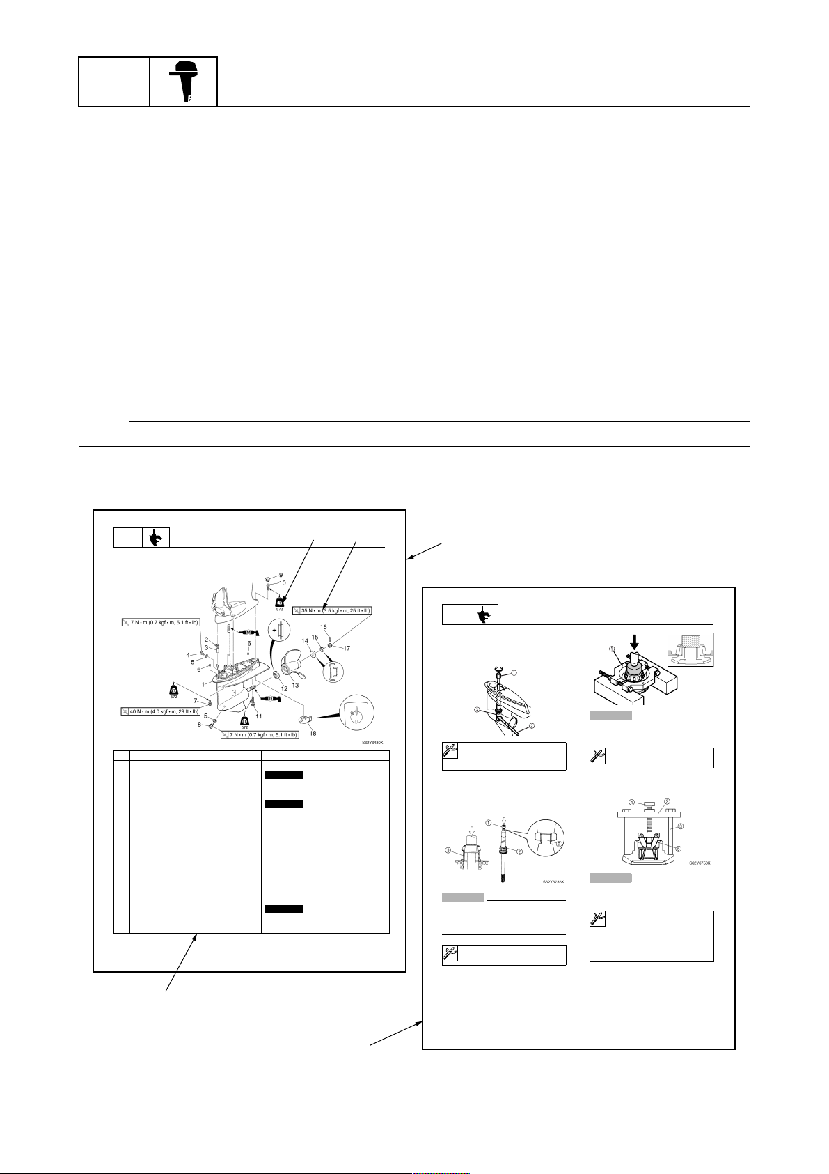
LOWR
Lower unit
No. Part name Q’ty Remarks
1 Lower unit 1
2 Plastic tie 1
3Hose 1
4 Check screw 1
5 Gasket 2
6 Dowel pin 2
7 Bolt 4 M10 40 mm
8 Drain screw 1
9Grommet 1
10 Bolt 1 M10 45 mm
11 Bolt 1 M8 60 mm
12 Thrust washer 1
13 Propeller 1
14 Washer 1
15 Washer 1
16 Cotter pin 1
17 Propeller nut 1
18 Trim tab 1
6-5
Lower unit
Not reusable
Not reusable
Not reusable
3
4
2
62Y5A11
1
LOWR
Removing the drive shaft
1. Remove the drive shaft assembly and
pinion, and then pull out the forward
gear.
Disassembling the drive shaft
1. Install the pinion nut 1, tighten it finger
tight, and then remove the drive shaft
bearing 2 using a press.
CAUTION:
• Do not press the drive shaft threads
directly.
• Do not reuse the bearing, always
replace it with a new one.
Disassembling the forward gear
1. Remove the taper roller bearing from the
forward gear using a press.
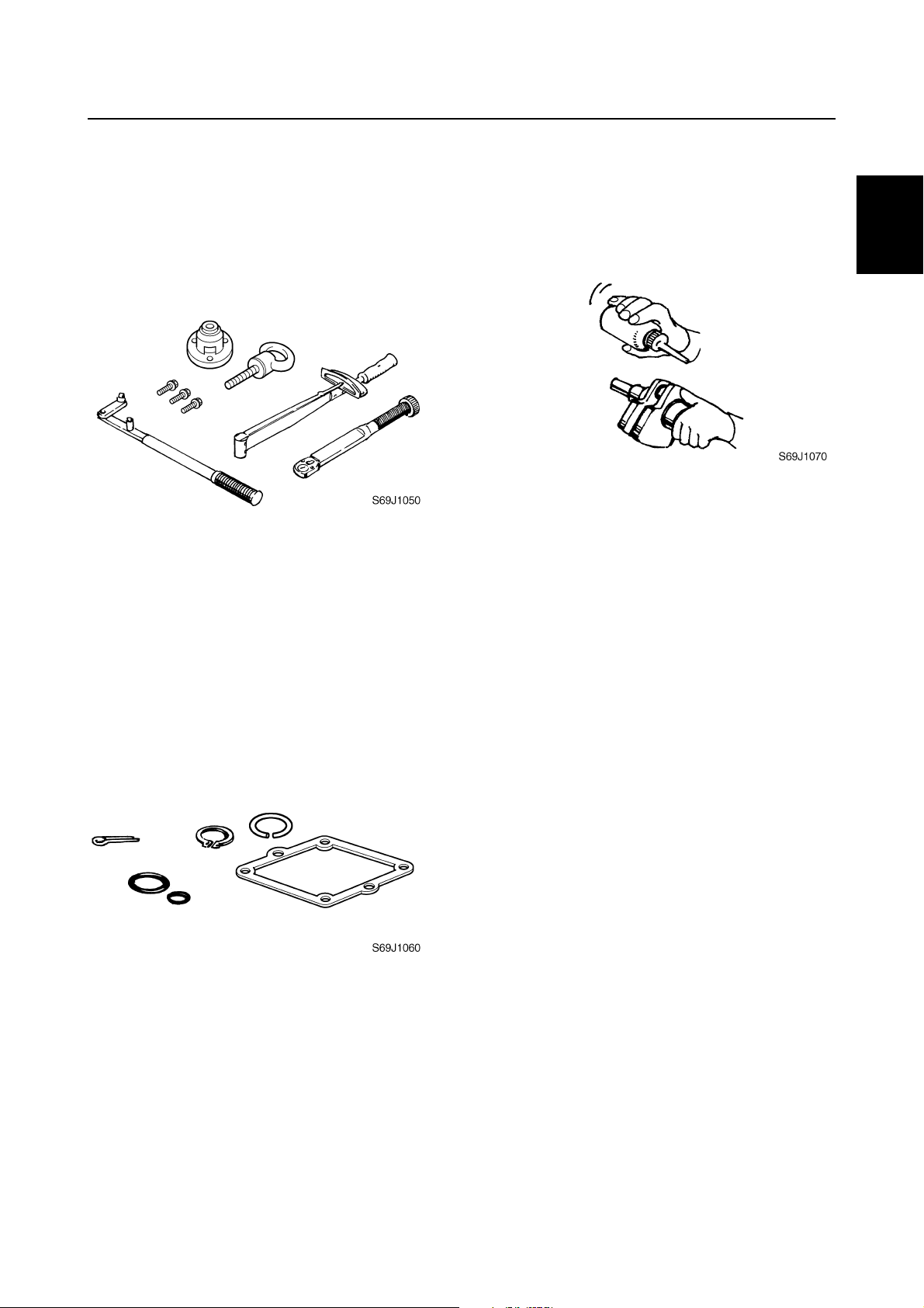
Lower unit
S62Y6850K
Drive shaft holder 4 1: 90890-06518
Pinion nut holder 2: 90890-06505
Socket adapter 2 3: 90890-06507
Bearing inner race attachment 3:
90890-06639
CAUTION:
Do not reuse the bearing, always replace
it with a new one.
Bearing separator 1: 90890-06534
2. Remove the needle bearing from the forward gear.
CAUTION:
Do not reuse the bearing, always replace
it with a new one.
a
Stopper guide plate 2: 90890-06501
Stopper guide stand 3:
90890-06538
Bearing puller 4: 90890-06535
Bearing puller claw 1 5:
90890-06536
S62Y6740K
1-1
5
6-19
62Y5A11
60V3E11
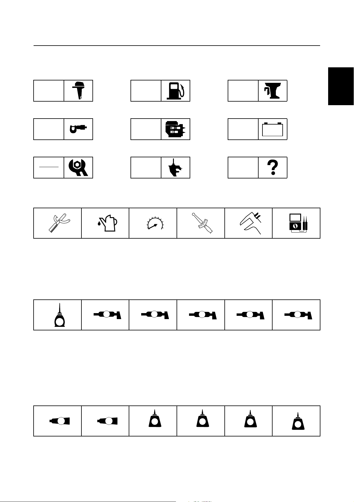
Symbols
T
R
.
.
D
The symbols below are designed to indicate the content of a chapter.
How to use this manual
General information
GEN
INFO
Specifications
SPEC
Periodic checks and adjustments
CHK
ADJ
Symbols 1 to 6 indicate specific data.
123456
Fuel system
FUEL
Power unit
POWR
Lower unit
LOWR
Bracket unit
BRKT
Electrical systems
ELEC
Troubleshooting
– +
TRBL
SHTG
1
2
3
4
Special tool
1
Specified oil or fluid
2
Specified engine speed
3
Specified tightening torque
4
Symbols 7 to B in an exploded diagram indicate the grade of lubricant and the lubrication point.
7890AB
A M
E
Apply 2-stroke outboard motor oil
7
Apply water resistant grease (Yamaha grease A)
8
Apply molybdenum disulfide grease
9
Apply corrosion resistant grease
0
(Yamaha grease D)
Symbols C to H in an exploded diagram indicate the type of sealant or locking agent and the application point.
CDEFGH
GM
4
LT
271
Specified measurement
5
Specified electrical value
6
(resistance, voltage, electric current)
C I
Apply low temperature resistant grease
A
(Yamaha grease C)
Apply injector grease
B
LT
242
LT
572
SS
5
6
7
8
9
Apply Gasket Maker
C
Apply Yamabond No. 4
D
Apply LOCTITE 271 (red)
E
60V3E11
Apply LOCTITE 242 (blue)
F
Apply LOCTITE 572
G
Apply silicon sealant
H
1-2
GEN
INFO
General information
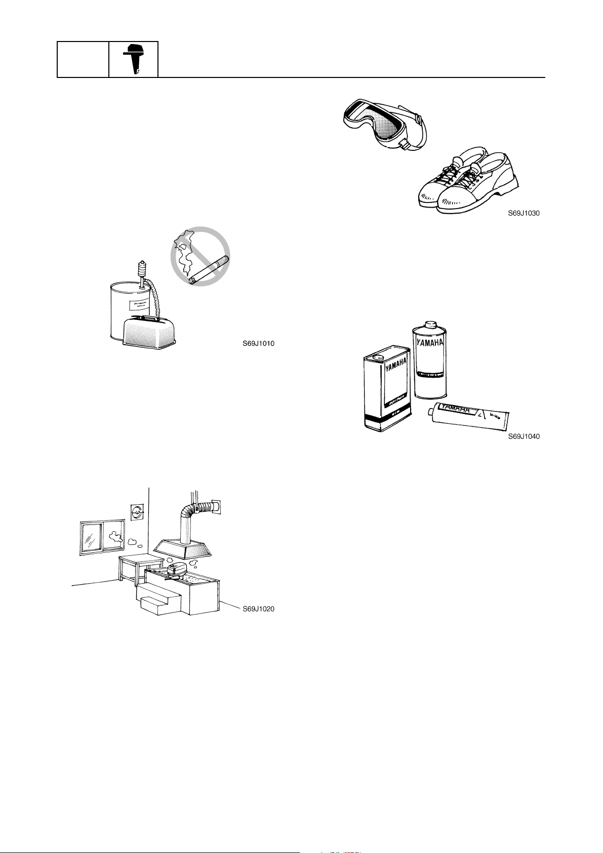
Safety while working
To prevent an accident or injury and to
ensure quality service, follow the safety procedures provided below.
Fire prevention
Gasoline is highly flammable.
Keep gasoline and all flammable products
away from heat, sparks, and open flames.
Ventilation
Gasoline vapor and exhaust gas are heavier
than air and extremely poisonous. If inhaled
in large quantities they may cause loss of
consciousness and death within a short time.
When test running an engine indoors (e.g., in
a water tank) be sure to do so where adequate ventilation can be maintained.
1
Parts, lubricants, and sealants
Use only genuine Yamaha parts, lubricants,
and sealants or those recommended by
Yamaha, when servicing or repairing the outboard motor.
Under normal conditions, the lubricants mentioned in this manual should not harm or be
hazardous to your skin. However, you should
follow these precautions to minimize any risk
when working with lubricants.
Self-protection
Protect your eyes by wearing safety glasses
or safety goggles during all operations involving drilling and grinding, or when using an air
compressor.
Protect your hands and feet by wearing protective gloves and safety shoes when necessary.
1-3
1. Maintain good standards of personal and
industrial hygiene.
2. Change and wash clothing as soon as
possible if soiled with lubricants.
3. Avoid contact with skin. Do not, for
example, place a soiled rag in your
pocket.
4. Wash hands and any other part of the
body thoroughly with soap and hot water
after contact with a lubricant or lubricant
soiled clothing has been made.
5. To protect your skin, apply a protective
cream to your hands before working on
the outboard motor.
60V3E11
Safety while working
6. Keep a supply of clean, lint-free cloths for
wiping up spills, etc.
Good working practices
Special service tools
Use the recommended special service tools
to protect parts from damage. Use the right
tool in the right manner—do not improvise.
Tightening torques
Follow the tightening torque specifications
provided throughout the manual. When tightening nuts, bolts, and screws, tighten the
large sizes first, and tighten fasteners starting
in the center and moving outward.
Non-reusable parts
Always use new gaskets, seals, O-rings, cotter pins, circlips, etc., when installing or
assembling parts.
Disassembly and assembly
1. Use compressed air to remove dust and
dirt during disassembly.
2. Apply engine oil to the contact surfaces
of moving parts before assembly.
3. Install bearings with the manufacture
identification mark in the direction indicated in the installation procedure. In
addition, be sure to lubricate the bearings
liberally.
4. Apply a thin coat of water-resistant
grease to the lip and periphery of an oil
seal before installation.
5. Check that moving parts operate normally after assembly.
1
2
3
4
5
6
7
8
9
60V3E11
1-4
GEN
INFO
General information
Identification
Applicable models
This manual covers the following models.
Applicable models
Z250DETO, LZ250DETO
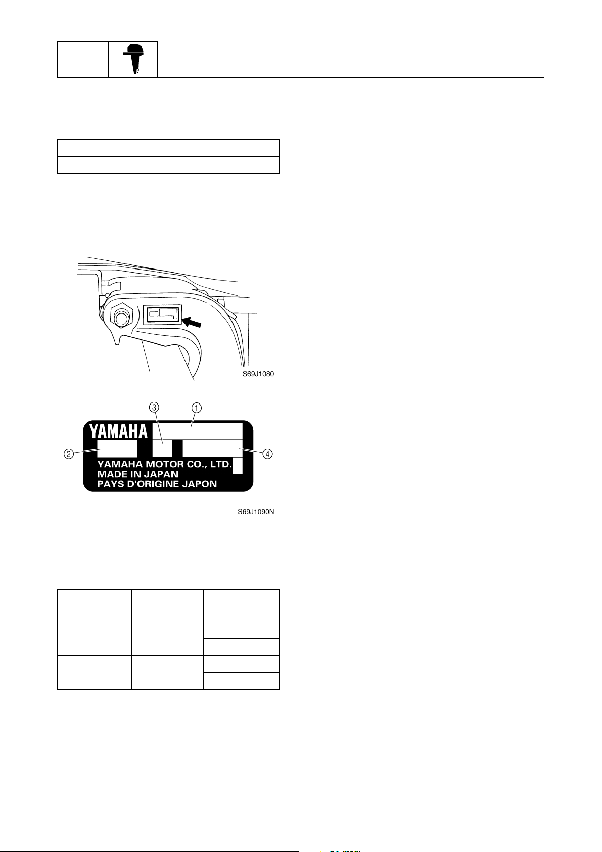
Serial number
The outboard motor serial number is
stamped on a label attached to the port
clamp bracket.
1
Model name
1
Approved model code
2
Transom height
3
Serial number
4
Model name
Approved
model code
Z250DETO 60V
LZ250DETO 60W
1-5
Starting
serial No.
X: 1000001–
U: 1000001–
X: 1000001–
U: 1000001–
60V3E11
Identification / Features and benefits
Features and benefits
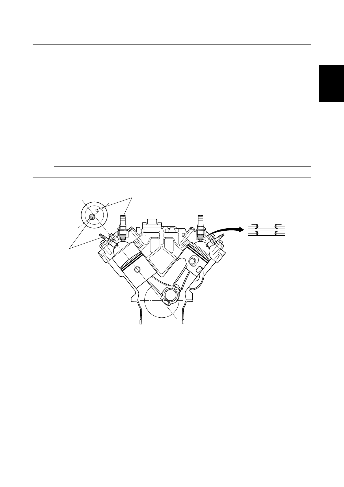
Cylinder body and cylinder head
Hemispherical combustion chambers have been incorporated in the cylinder head to realize a high
compression ratio of 6.2.
The exhaust ports have been chamfered to reduce loss of the exhaust gases.
Also, an exhaust shell has been adopted to allow exhaust gases flow out smoothly.
The plateau honing process has been used in the cylinder sleeves to reduce friction.
The spark plugs have been offset from the center of the cylinder head to keep the fuel injectors
away from high temperatures.
The fuel injectors are located on the exhaust side of the combustion chambers. Fuel is injected
toward the tumble due to scavenging to obtain the optimum air-fuel mixture.
Special twin corrugated washers have been adopted in the injectors to prevent fuel in an injector
from carbonizing due to exhaust heat.
NOTE:
Install the washers so that the shorter metal guard ends contact each other.
1
1
1
2
3
4
2
Injector
1
Spark plug
2
Corrugated washers
3
3
5
6
S60V1130
7
8
9
60V3E11
1-6
GEN
INFO
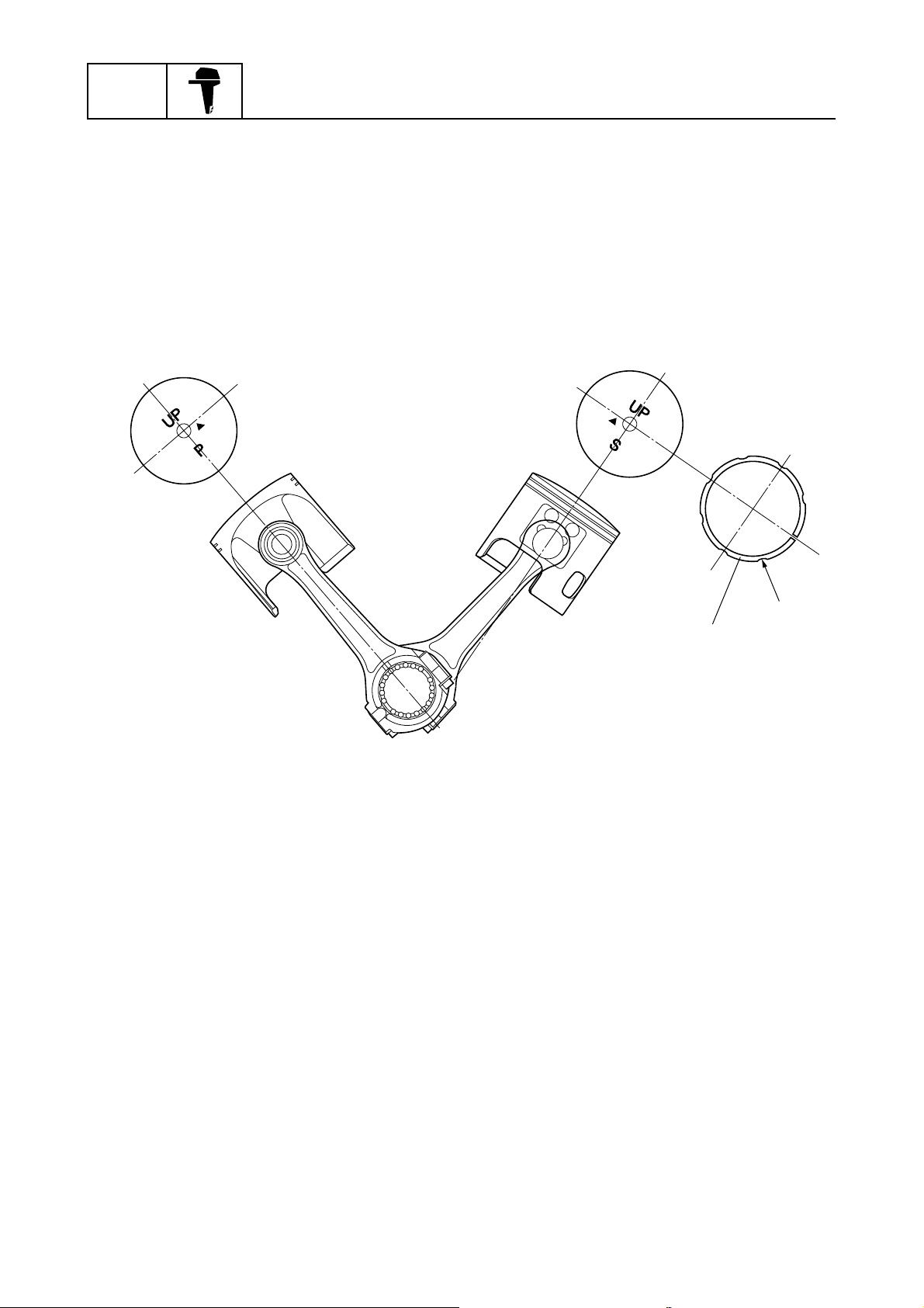
Pistons and connecting rods
The pistons and connecting rods have been processed as follows to increase durability.
• Heat resisting, lightweight aluminum forged pistons have been adopted.
• Highly carbonized connecting rods have been adopted.
• The piston rings have been processed with a hard chrome plating that has a thickness of 50
microns.
• The big end bearings have been processed with 18 rollers, 2 rollers more than those of the VX250
(250C), and with oil grooves around the outer race of the bearings.
• The small ends of the connecting rods have been processed with a special heat treatment.
• Oil grooves have been processed around the outer peripheries of the 2nd piston rings.
General information
2nd piston ring
1
Oil groove
È
È
1
S60V1140
1-7
60V3E11
Features and benefits
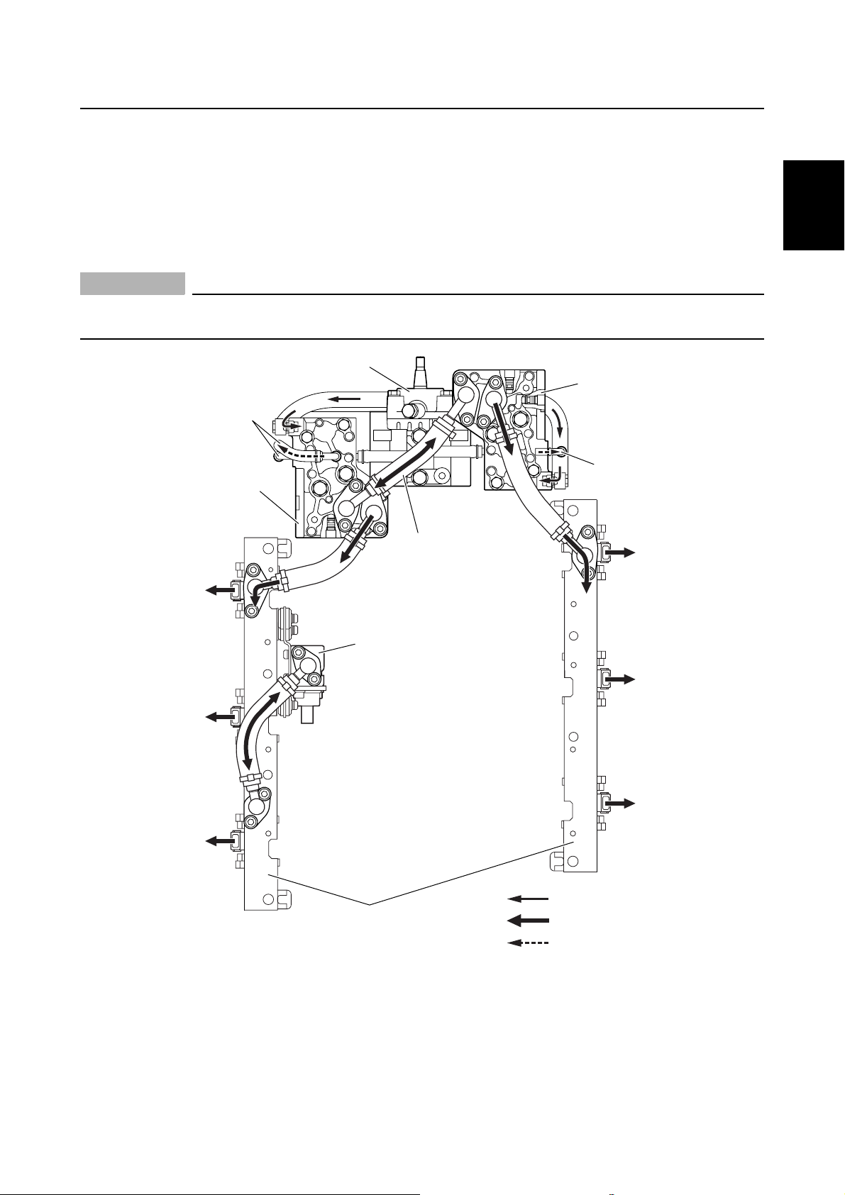
Fuel injection pumps
Twin fuel injection pumps with pressure regulators have been adopted to obtain a high fuel pressure
of 7 MPa (71 kg/cm
The fuel injection pressure is detected by the fuel pressure sensor installed on the fuel rail. Protectors have been incorporated on the fuel pressure sensor to reduce vibrations conducting to the sensor.
High-pressure fuel injection obtains a better air-fuel mixture due to finer atomization.
CAUTION:
Do not disassemble the fuel injection pumps. The proper facilities and special service tools
are required to reassemble them.
2
, 1,015 psi).
1
2
1
2
8
0
3
2
5
4
3
7
9
A
3
4
5
6
7
B
Fuel pump drive unit
1
High-pressure fuel pump with
2
pressure regulator
Fuel return hose
3
Pressure equalizing pipe
4
Fuel pressure sensor
5
Fuel rail
6
60V3E11
Injector #1
7
Injector #2
8
Injector #3
9
Injector #4
0
Injector #5
A
Injector #6
B
6
: È
: É
: Ê
Medium-pressure fuel
È
(suction)
High-pressure fuel
É
Fuel return
Ê
8
S60V1150
9
1-8
GEN
INFO
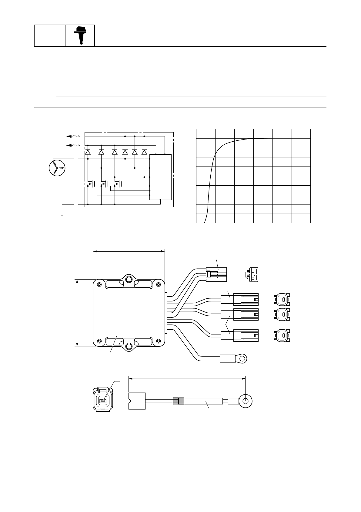
Flywheel magnet
A large capacity Rectifier Regulator has been adopted to obtain a charging current of 50 amperes
for battery charging capabilities.
An isolator has been incorporated into the Rectifier Regulator unit.
NOTE:
An optional battery charging cable has been made available for use with an accessory battery.
1
2
3
G
4
4
G
G
B
General information
R
R
È
5
Ê
É
50
45
40
35
30
25
20
15
10
93 mm (3.66 in)
88 mm (3.46 in)
8
0551,000 2,000 3,000 4,000 5,000 6,000
Ë
6
R
R
7
G
G
7
G
B
B
3.8 m (12.5 ft) / 2.7 m (9 ft)
Fuse
1
Battery 1
2
Battery 2
3
Lighting coil
4
Control circuit
5
1-9
9
P/No. 69J-81949-00 (3.8 m [12.5 ft])
68F-81949-00 (2.7 m [9 ft])
Blue
6
Black
7
Rectifier Regulator unit
8
Isolator cable (optional)
9
Charging circuit
È
Charging output
É
Charging current (A)
Ê
Engine speed (r/min)
Ë
S60V1160
60V3E11
Features and benefits
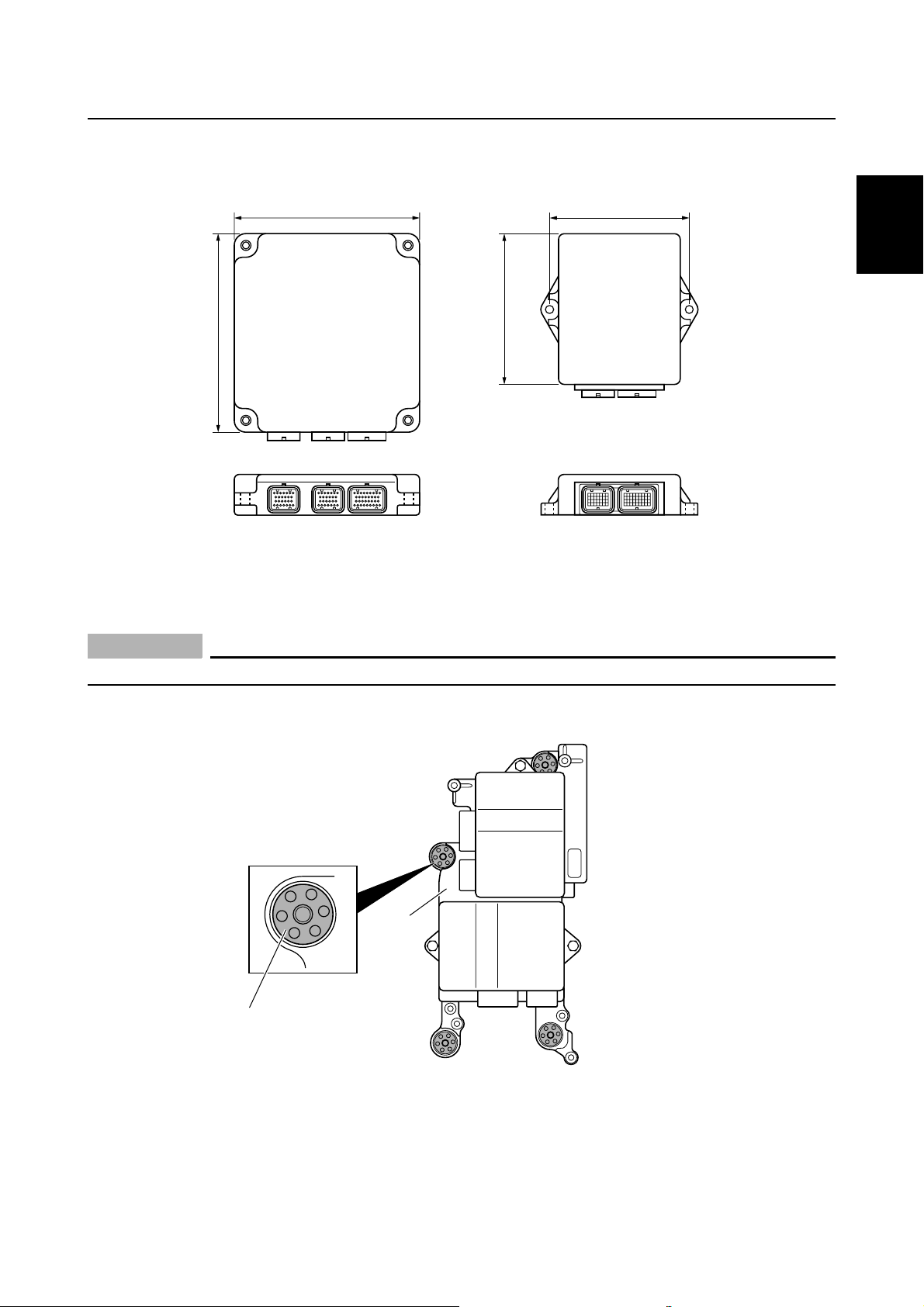
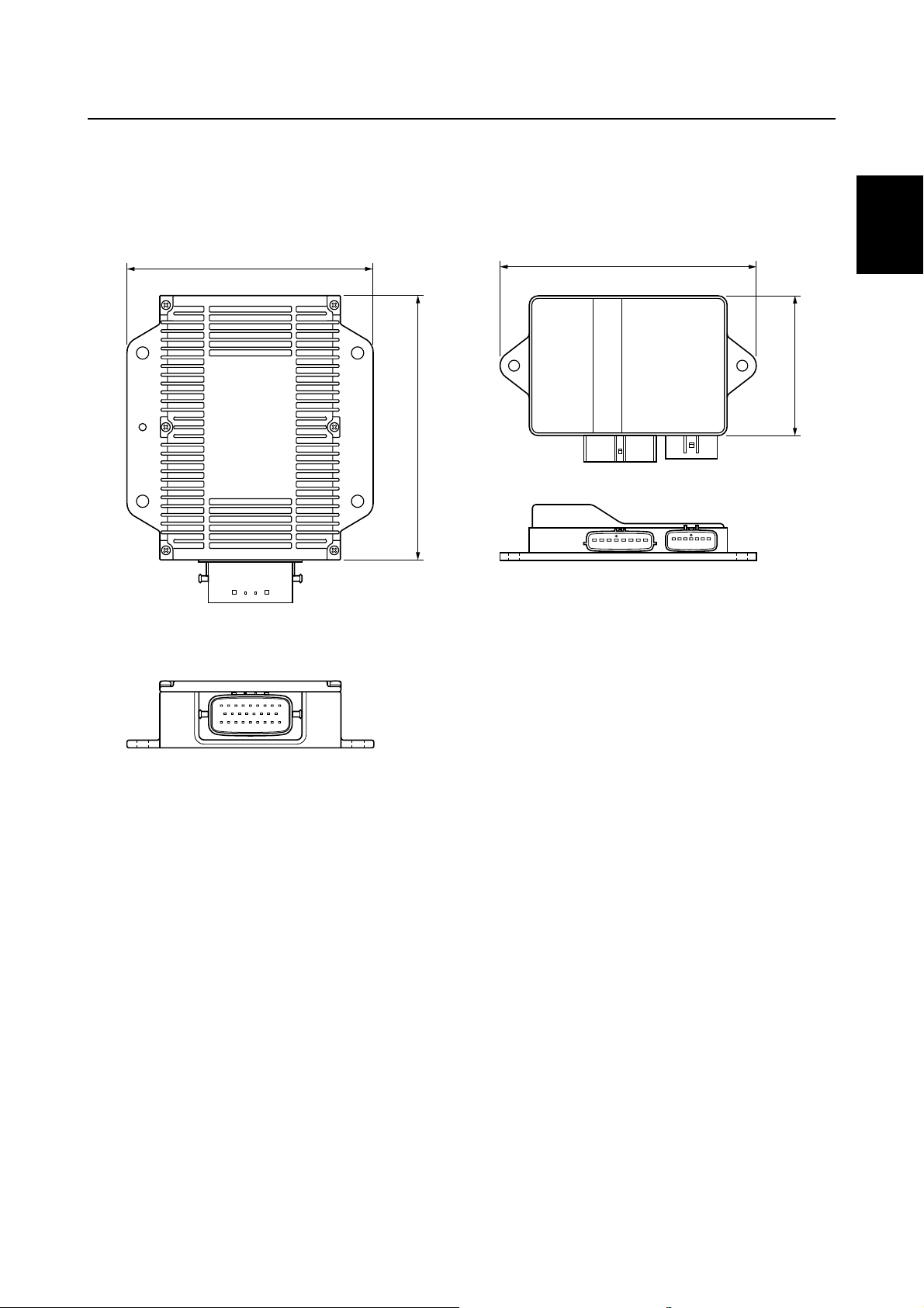
ECM (Electronic Control Module)
A small and lightweight ECM has been adopted to make the surrounding components compact.
168 mm (6.61 in)
ECM
135 mm (5.31 in)
180 mm (7.09 in)
Z200
Z200N
Silicon grommets (navy blue) have been adopted for installing the ECM and injector driver brackets,
and to reduce vibration conducting from the engine.
CAUTION:
Do not apply fuel or oil to the grommets, otherwise they can be damaged.
126 mm (4.96 in)
ECM
Z250
Z250D
S60V1170
1
2
3
4
5
1
Silicon grommet (navy blue)
1
ECM and injector drivers mounting bracket
2
2
S60V1180
6
7
8
9
60V3E11
1-10
GEN
INFO
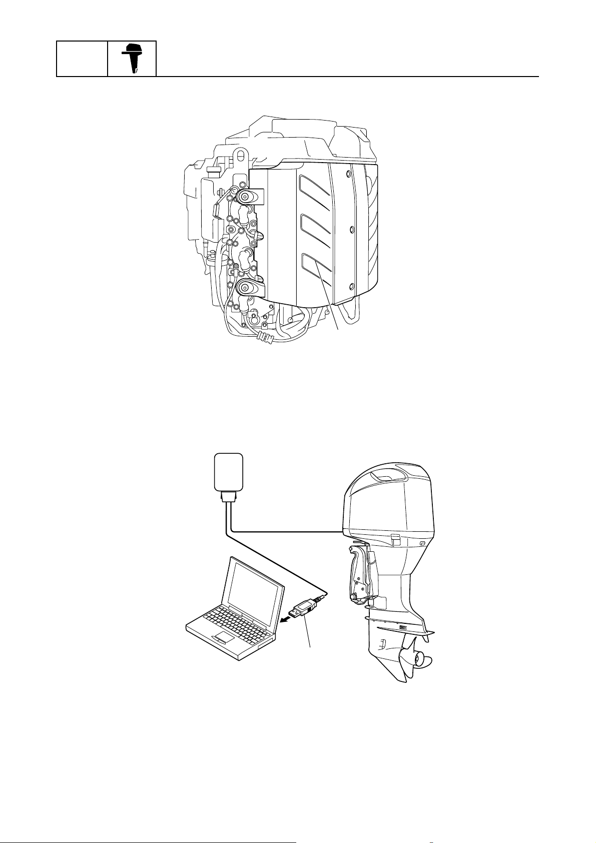
A large cover has been adopted to protect the electrical components from water.
General information
1
S60V1190
Large electrical component cover
1
The memory in the ECM has been increased from 128 bytes to 256 bytes to expand the functions of
the YDIS.
A communication cable with a USB connector has been made available.
1
USB connector
1
1-11
S60V1200
60V3E11
Features and benefits
Injector drivers
Twin small and lightweight injector drivers have been adopted to make the surrounding components
compact.
Maintenance has been made easy and low cost for replacing the driver has been obtained.
170 mm (6.69 in)
180 mm (7.09 in)
175 mm (6.89 in)
Z250
Z250D
1
2
96 mm (3.78 in)
3
4
5
Z200
Z200N
6
S60V1210
7
8
9
60V3E11
1-12
GEN
INFO
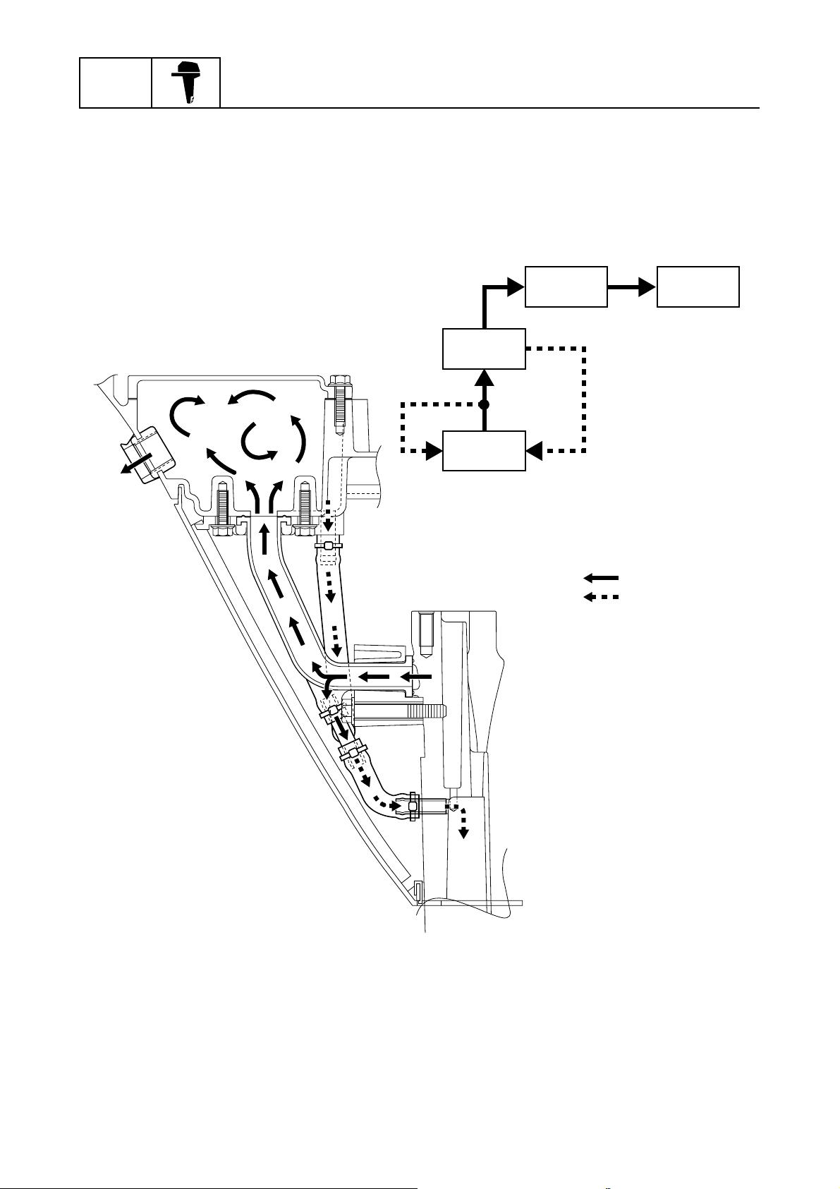
Idle silencer
An idle silencer has been incorporated in the bottom cowling.
Exhaust gases are led into the idle silencer from the upper case and expanded, and then discharged into the atmosphere.
The idle hole has been positioned higher at the rear of the bottom cowling to decrease the resistance of the exhaust back pressure.
General information
3 4
2
1
Upper case
1
Silencer
2
Idle hole
3
Atmosphere
4
Exhaust gas/water
È
Water
É
: È
: É
S60V1220
1-13
60V3E11
Features and benefits
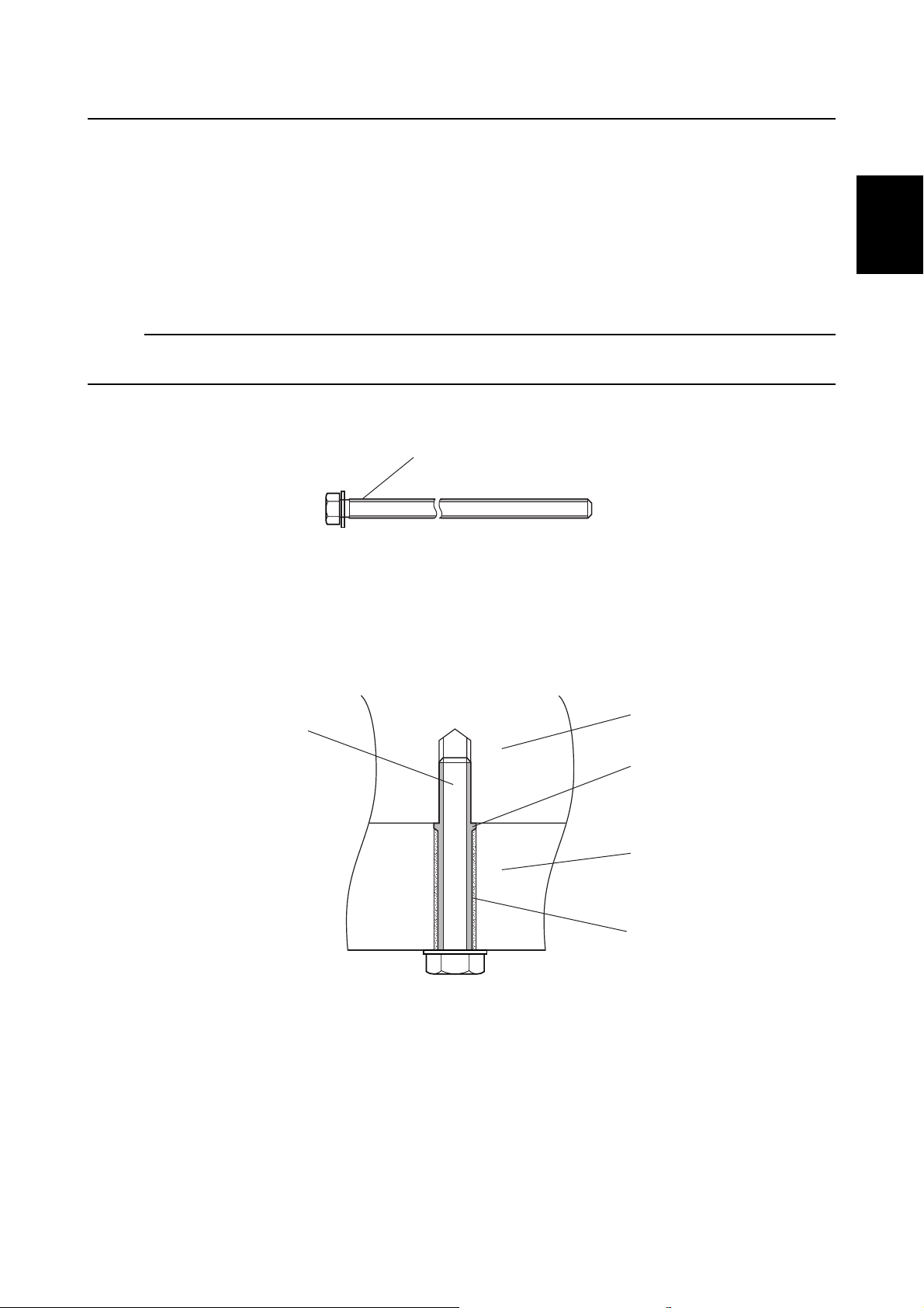
Power unit mounting bolts
Bolts coated with a sealing agent have been adopted to provide a sealing function to the bolts. The
sealing agent secures the axial force of the bolts after they are tightened to the specified torque,
thus preventing the bolts from coming loose. The sealing agent also helps prevent the bolts from
sticking if salt water enters into the thread holes and crystallizes.
Also, the bolts can be removed even if corroded particles have collected in and choked the bolt
holes because the sealing agent also acts as an insulator. As a result, servicing such as removing
the power unit has been made easy.
NOTE:
Clean the bolt surface, and then apply LOCTITE 572 to the bolt to act as a sealing agent when reusing the power unit mounting bolts.
1
2
2
1
È
3
4
5
3
4
5
6
7
Sealing agent coating
1
Bolt
2
Cylinder block
3
Sealing agent
4
Upper case
5
Corroded particles
6
60V3E11
É
6
Power unit mounting bolt
È
Bolt hole description
É
8
S60V1230
9
1-14
GEN
INFO
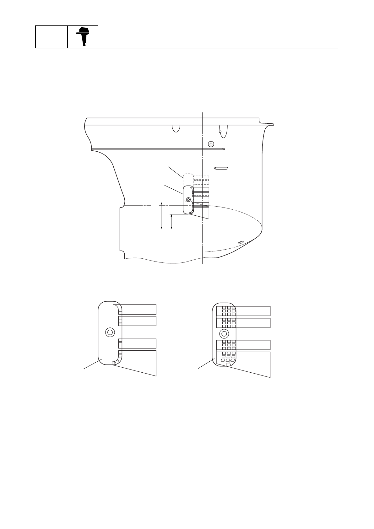
Cooling water inlet
A low positioned cooling water inlet, which is 30 mm (1.18 in) lower than that of the SX250 (250B),
has been adopted to secure the cooling water supply.
An optional dynamic pressure type inlet cover to secure the cooling water supply has been made
available if the outboard motor is to be mounted at an elevated position.
General information
SX250
250B
Z250
Z250D
12
Dynamic pressure inlet cover (optional)
1
Standard inlet cover
2
70 mm (2.76 in)
40 mm (1.57 in)
S60V1250
1-15
60V3E11
Features and benefits
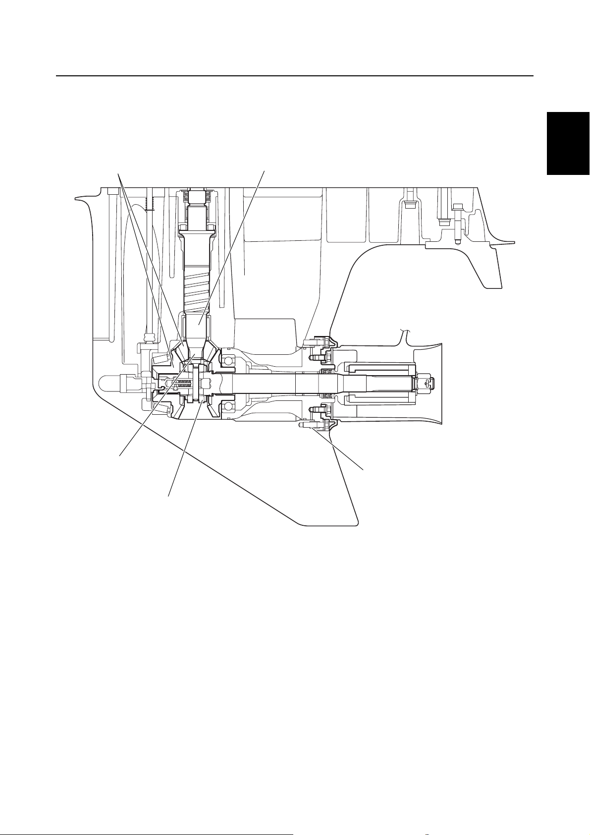
Transmission components
Materials have been modified, and the heat treatment and shot peening processes have been
applied to the transmission components to increase durability.
1
2
1
2
3
4
5
5
4
Shot peening processing
1
Form rolling processing
2
Collar added
3
Cemented steel with shot peening processing
4
13-tooth spline
5
3
6
S60V1260
7
8
9
60V3E11
1-16
GEN
INFO
General information
Technical tips
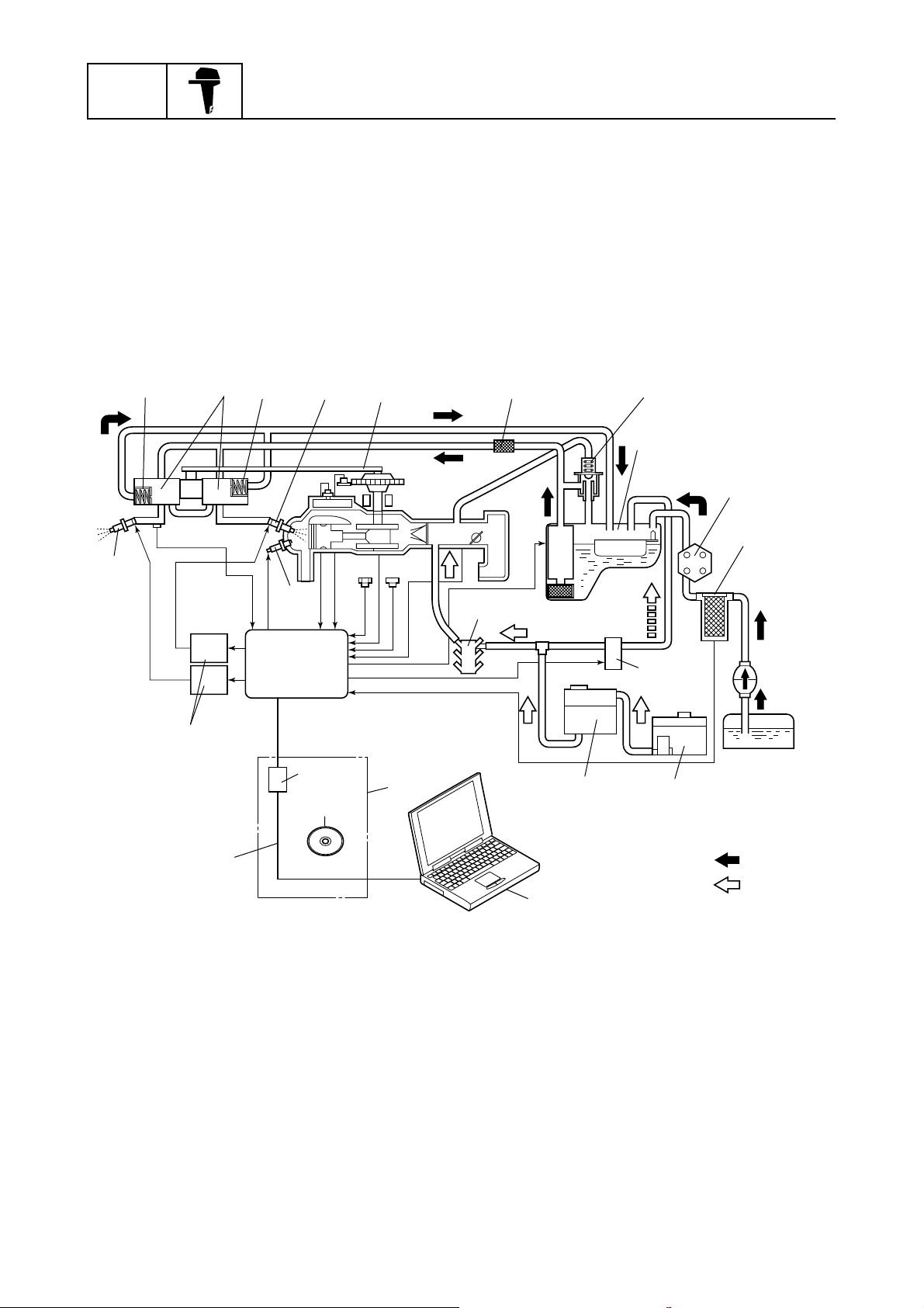
Electronic control system
The electronic control system ensures optimum combustion under various operating conditions to
provide a high power output with low fuel consumption and low emissions.
The ECM (Electronic Control Module) mainly controls ignition timing, fuel injection timing, and fuel
injection volume with various signals received from sensors equipped on the outboard motor.
The Yamaha Self-Diagnosis function has been incorporated in the ECM for easier servicing. Troubleshooting the outboard motor can be accomplished by monitoring the engine conditions and operating the electrical components with a personal computer and the optional Yamaha Diagnostic
System (YDIS) software.
0
9
R
A
0
Q
1
B
2
C
D
E
F
3
4
G
D
5
78
M
1
P
O
Engine temperature sensor
1
Crank position sensor
2
Pulser coil
3
Throttle position sensor
4
Electric fuel pump
5
Water detection switch
6
Atmospheric pressure sensor
7
Intake air temperature sensor
8
Fuel pressure sensor
9
High-pressure fuel regulator
0
High-pressure fuel pump
A
Injectors #1, #3, #4
B
Drive belt
C
ECM
N
T
S
Fuel filter
D
Fuel pressure regulator
E
Vapor separator
F
Fuel pumps
G
Primer pump
H
Fuel tank
I
Remote oil tank
J
Oil tank
K
Electric oil pump
L
Oil pump
M
Adapter
N
Communication cable
O
Injector drivers
P
U
K
L
J
Spark plug
Q
Injectors #2, #5, #6
R
Service tool (optional)
S
Software (CD-ROM)
T
Personal computer
U
Gasoline
È
Oil
É
6
H
I
: È
: É
S60V1270
1-17
60V3E11
Technical tips
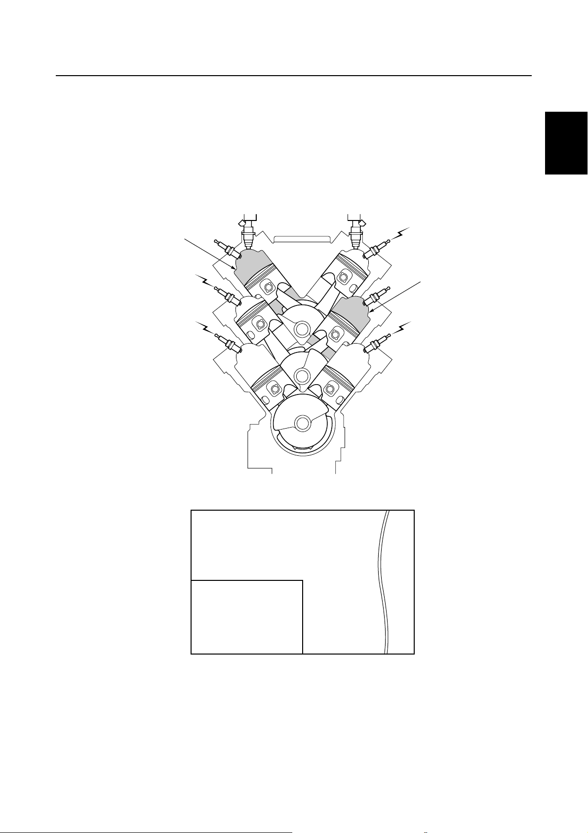
Partial cylinder operation
This outboard motor controls the partial cylinder operation when the gear shift is in the neutral position to reduce vibration and noise and to obtain a lower fuel consumption.
When the neutral position of the gear shift is detected by the shift position switch, the ECM shuts off
the ignition and fuel injection of cylinders #2 and #3.
If the throttle valves are opened further, the ignition and fuel injection of cylinders #5 and #6 are also
shut off.
When the gear shift is shift into gear, all cylinders are activated.
1
1
2
5,500
#2
#4
#6
È
2
#1
#3
#5
1
3
4
5
6
7
1,750
É
0790
Shut off
1
Cylinders #1 and #4 activated
2
Cylinders #1, #4, #5 and #6 activated
3
60V3E11
3
Ê
Partial cylinder operation in neutral
È
Engine speed (r/min)
É
Throttle valve opening angle (degree)
Ê
8
S60V1280
9
1-18

GEN
INFO
Fail-safe control
If the electrical components malfunction, the ECM controls the ignition and fuel injection as shown in
the table.
Faulty component Criterion Ignition control Fuel control
Pulser coil Incorrect signal Fixed to 7° BTDC
Crank position sensor No signal Fixed to 7° BTDC Fixed to 127° BTDC
General information
Injection stopped as follows:
Faulty coil
Injection
stopped cylinder
#1 #6
#2 #1
#3 #2
#4 #3
#5 #4
#6 #5
Throttle position
sensor
Engine temperature
sensor
Atmospheric pressure
sensor
Intake air temperature
sensor
Fuel pressure sensor
Injectors
Shift position switch
Throttle opening angle
is detected at –4.1° or
less, or 90° or more
Resistance is detected
at 0.35 kΩ or less, or
701 kΩ or more
Pressure is detected at
25 kPa (0.25 kgf/cm
2
)
or less, or 114 kPa
(1.16 kgf/cm
2
) or more
Temperature is
detected at –40 °C
(–40 °F) or less, or
80 °C (176 °F) or more
Signal is detected at
0.2 V or less, or 4.7 V
or more
No signal at
2,000 r/min or less
Off signal is detected
while cranking engine
Fixed output to 4.8 V
Fixed to 7° BTDC Normal control
Normal control
Normal control
Normal control
Fixed output to 101 kPa
(1 kgf/cm
2
)
Fixed output to 5 °C
(41 °F)
Fixed output to 7 MPa
2
(71 kgf/cm
)
Fixed to 7° BTDC Normal control
Normal control
1-19
60V3E11

Technical tips
Warning control
This outboard motor is equipped with warning control functions to avoid serious engine damage.
The engine speed is limited to approximately 2,000 r/min if the engine overheats, if there is insufficient oil, if there is water in the fuel, or if a dual engine system (DES) is operated.
When a switch turns on, the engine speed is controlled as shown in the table.
Overheat
switch
Cylinders #2, #3, #5, and #6 misfire in order and in 2.5 second intervals when the engine is running
at 2,000 r/min or more.
Cylinders #1 and #4 are always ignited.
The warning control mode is deactivated when the throttle opening angle is less than 10°. Even if a
sensor switch turns off, the warning control mode continues.
Over-revolution control
This outboard motor is equipped with an over-revolution control system to protect the engine.
If the engine speed exceeds 6,150 r/min, the ignition and fuel injection are controlled as shown in
the table.
Oil level
sensor low
oil signal
DES
signal
Off All speed range
On Ignites Misfires
Water
detection
switch
Throttle opening angle
is less than 10°
Throttle opening angle
is 10° or more
Less than
2,000 r/min
2,000 r/min
or more
1
2
3
4
Engine speed (r/min) Cylinders ignited and injected Cylinders not ignited and injected
6,149 or less #1, #2, #3, #4, #5, #6
6,150 to 6,174 #1, #3, #4, #5, #6 #2
6,175 to 6,199 #1, #4, #5, #6 #2, #3
6,200 to 6,224 #1, #5, #6 #2, #3, #4
6,225 to 6,249 #1, #6 #2, #3, #4, #5
6,250 or more #1 #2, #3, #4, #5, #6
Shift cut control
This outboard motor is equipped with a shift cut system for easier shifting.
When shifting, the ignition of some cylinders is shut off as shown in the table.
Engine speed
(r/min)
Shift cut switch
Off N/A N/A N/A
On N/A
449 or less 450 to 2,999 3,000 or more
Cylinders #1, #3,
and #5 misfire
N/A
5
6
7
8
9
60V3E11
1-20
GEN
INFO
General information
Propeller selection
The performance of a boat and outboard
motor will be critically affected by the size
and type of propeller you choose. Propellers
greatly affect boat speed, acceleration,
engine life, fuel economy, and even boating
and steering capabilities. An incorrect choice
could adversely affect performance and
could also seriously damage the engine.
Use the following information as a guide for
selecting a propeller that meets the operating
conditions of the boat and the outboard
motor.
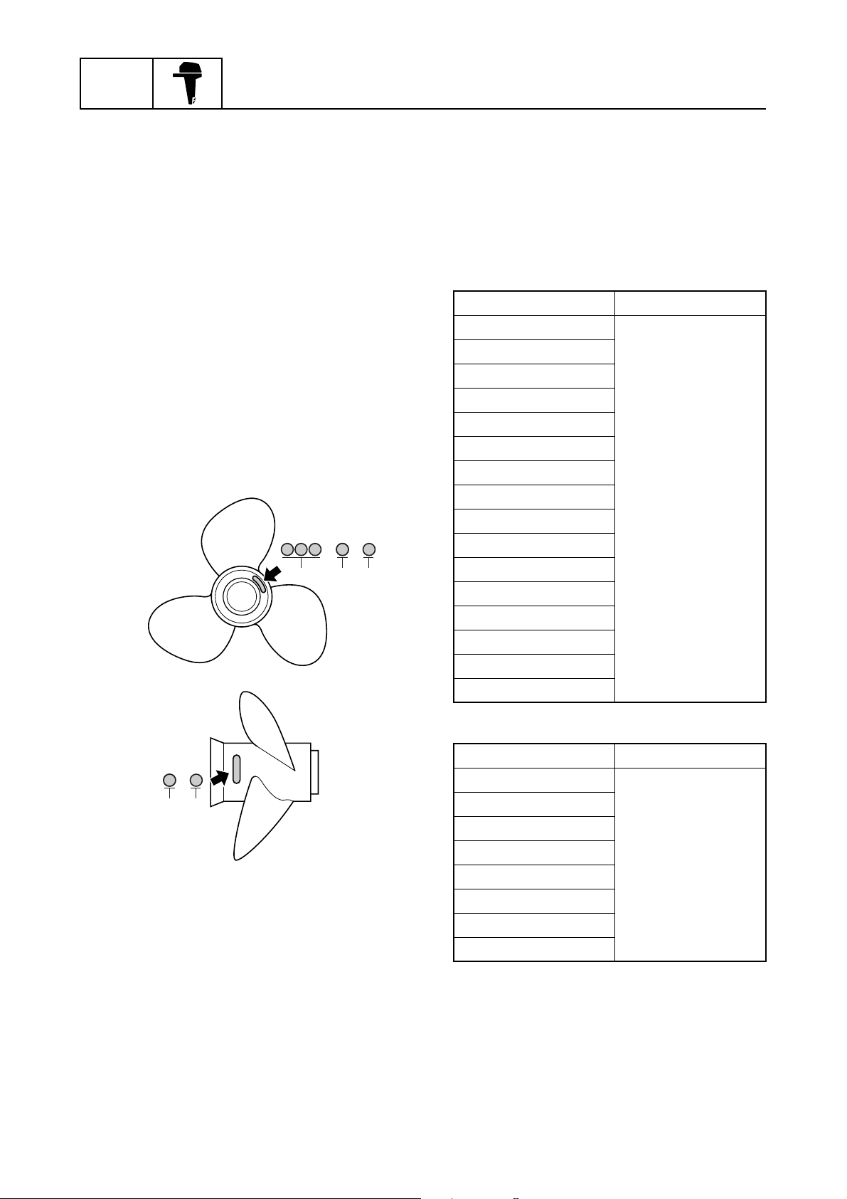
Propeller size
The size of the propeller is indicated on the
propeller boss end and on the side of the propeller boss.
× -
a
bc
S69J1100
1
Selection
When the engine speed is at the full throttle
operating range (4,500–5,500 r/min), the
ideal propeller for the boat is one that provides maximum performance in relation to
boat speed and fuel consumption.
Regular rotation model
Propeller size (in) Material
13 3/8 × 23 - M
13 3/8 × 25 - M
13 3/4 × 17 - M2
13 3/4 × 19 - M2
13 3/4 × 21 - M
14 1/2 × 19 - T
14 1/2 × 21 - T
14 1/2 × 23 - M
Stainless
14 3/4 × 25 - T
14 7/8 × 21 - M
15 × 17 - T
15 1/8 × 27 - T
15 1/4 × 15 - M
15 1/4 × 17 - M
15 1/4 × 19 - M
15 3/4 × 13 - M
-
b
c
Propeller diameter (in inches)
a
Propeller pitch (in inches)
b
Propeller type (propeller mark)
c
S60C1125
Counter rotation model
Propeller size (in) Material
13 3/8 × 23 - ML
13 3/4 × 17 - ML1
13 3/4 × 19 - ML1
13 3/4 × 21 - ML
Stainless
14 1/2 × 19 - TL
14 1/2 × 21 - TL
15 × 17 - TL
15 1/4 × 15 - ML
1-21
60V3E11
Propeller selection / Predelivery checks
Predelivery checks
To make the delivery process smooth and
efficient, the predelivery checks should be
completed as explained below.
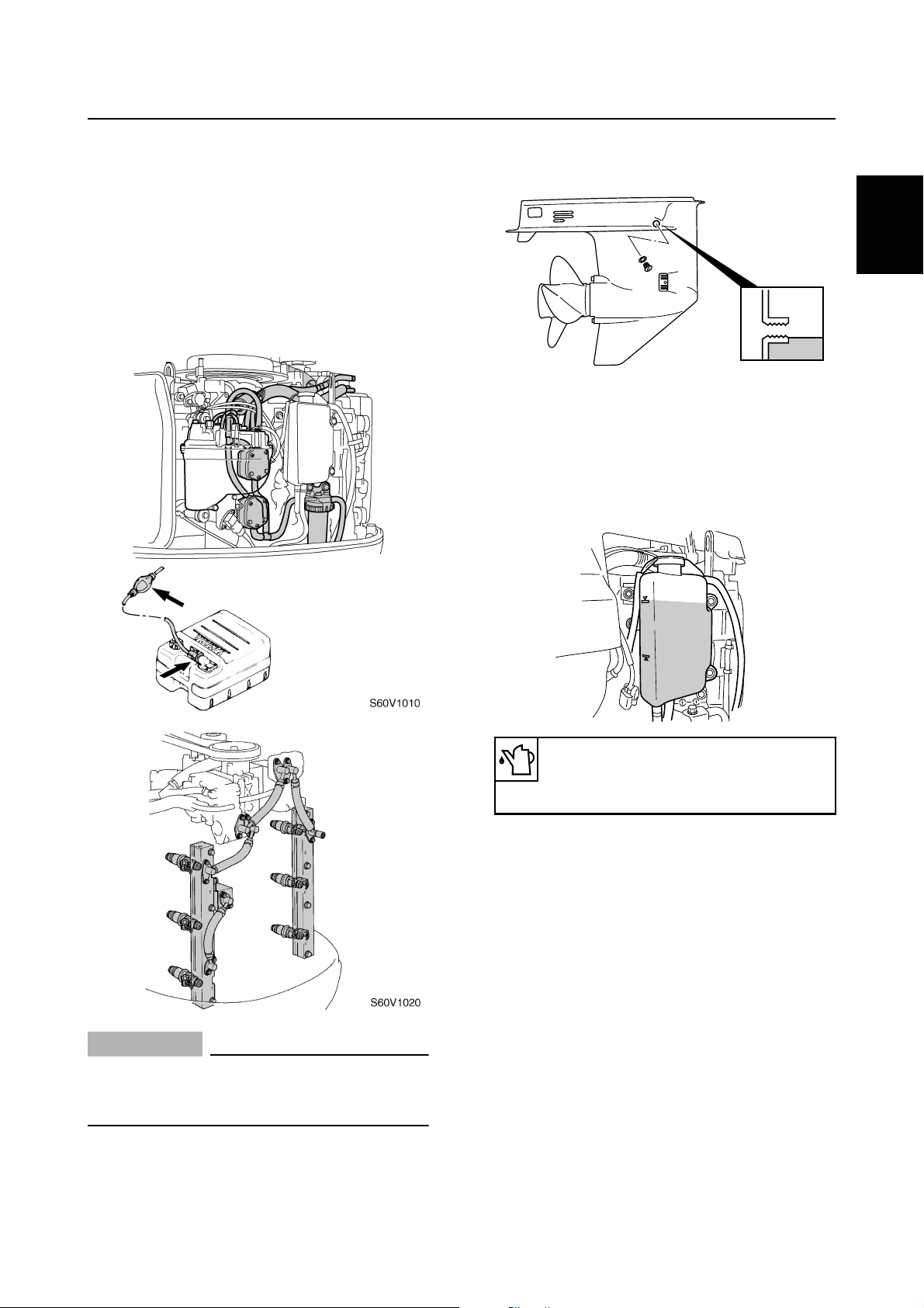
Checking the fuel system
1. Check that the fuel hoses are securely
connected and that the fuel tank is full
with fuel.
1
Checking the gear oil level
1. Check the gear oil level.
1
2
S60V1290
Checking the engine oil level
1. Check the engine oil level.
3
2. Make sure the oil level is between the
upper and lower level marks.
4
CAUTION:
• Use unleaded straight gasoline only.
• Do not use gasoline mixed with oil (premixed fuel).
Recommended engine oil:
YAMALUBE 2-stroke outboard
motor oil
5
S60V3260
6
7
8
9
60V3E11
1-22
GEN
INFO
General information
Checking the battery
1. Check the capacity, electrolyte level, and
specified gravity of the battery.
Recommended battery capacity:
CCA/SAE: 512 A
MCA/ABYC: 675 A
RC/SAE: 182 Minute
CCA/EN: 711 A
20HR/IEC: 100 Ah
Electrolyte specified gravity:
1.280 at 20 °C (68 °F)
2. Check that the positive and negative bat-
tery leads are securely connected.
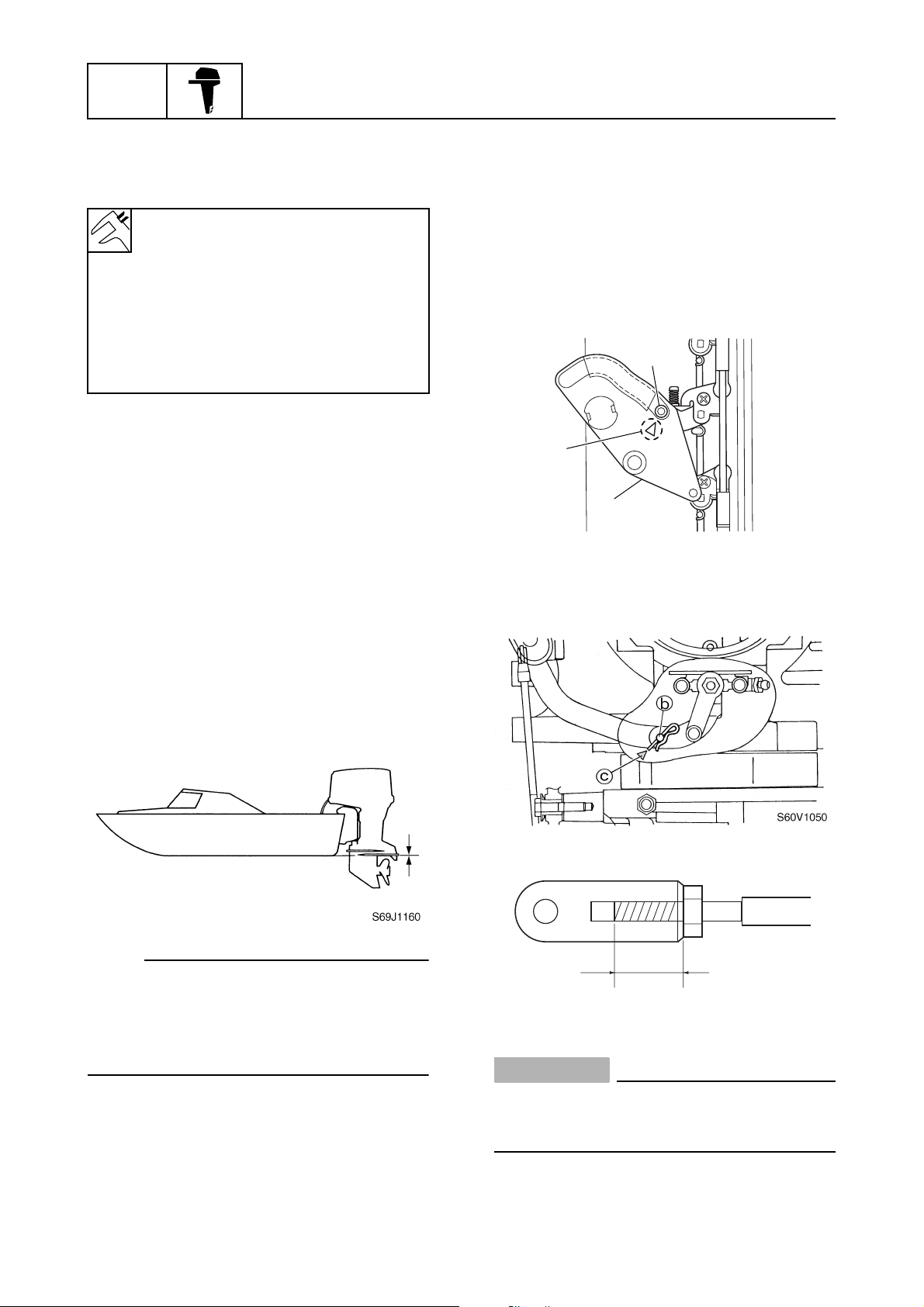
Checking the outboard motor
mounting height
1. Check that the anti-cavitation plate is
aligned with the bottom of the boat. If the
mounting height is too high, cavitation
will occur and propulsion will be reduced.
Also, the engine speed will increase
abnormally and cause the engine to
overheat. If the mounting height is too
low, water resistance will increase and
reduce engine efficiency.
Checking the remote control cables
1. Set the remote control lever to the neutral position and fully close the throttle
lever.
2. Check that the throttle cam 1 is in its
fully closed position and align the center
of the throttle cam roller 2 with the alignment mark a.
2
a
1
S60V1040
3. Check that the center of the set pin b is
aligned with the alignment mark c on
the bottom cowling.
NOTE:
The optimum mounting height is affected by
the combination of the boat and the outboard
motor. To determine the optimum mounting
height, test run the outboard motor at different heights.
2. Check that the clamp brackets are
secured with the clamp bolts.
1-23
d
S60C1190
CAUTION:
The shift/throttle cable joint must be
screwed in a minimum of 8.0 mm (0.31 in)
d
.
60V3E11
Predelivery checks
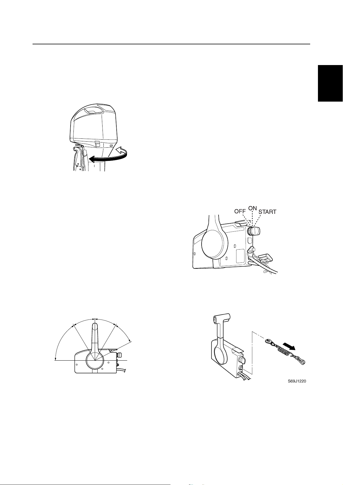
Checking the steering system
1. Check the steering friction for proper
adjustment.
2. Check that the steering operates
smoothly.
S60V1060
3. Check that there is no interference with
wires or hoses when the outboard motor
is steered.
Checking the gear shift and throttle
operation
1. Check that the gear shift operates
smoothly when the remote control lever
is shifted from neutral into forward or
reverse.
2. Check that there is no abnormal noise
produced when the outboard motor is
tilted up or down.
3. Check that there is no interference with
wires or hoses when the tilted-up outboard motor is steered.
4. Check that the trim meter points down
when the outboard motor is tilted all the
way down.
Checking the engine start switch and
engine shut-off switch
1. Check that the engine starts when the
engine start switch is turned to START.
2. Check that the engine turns off when the
engine start switch is turned to OFF.
1
2
3
4
5
2. Check that the throttle operates smoothly
when the remote control lever is shifted
from the fully closed position to the fully
open position a.
N
F
a
Checking the power trim and tilt
system
1. Check that the outboard motor tilts up
and down smoothly when operating the
power trim and tilt unit.
R
a
S69J1210
S60V1070
3. Check that the engine turns off when the
engine shut-off cord is pulled from the
engine shut-off switch.
6
7
8
9
60V3E11
1-24
GEN
INFO
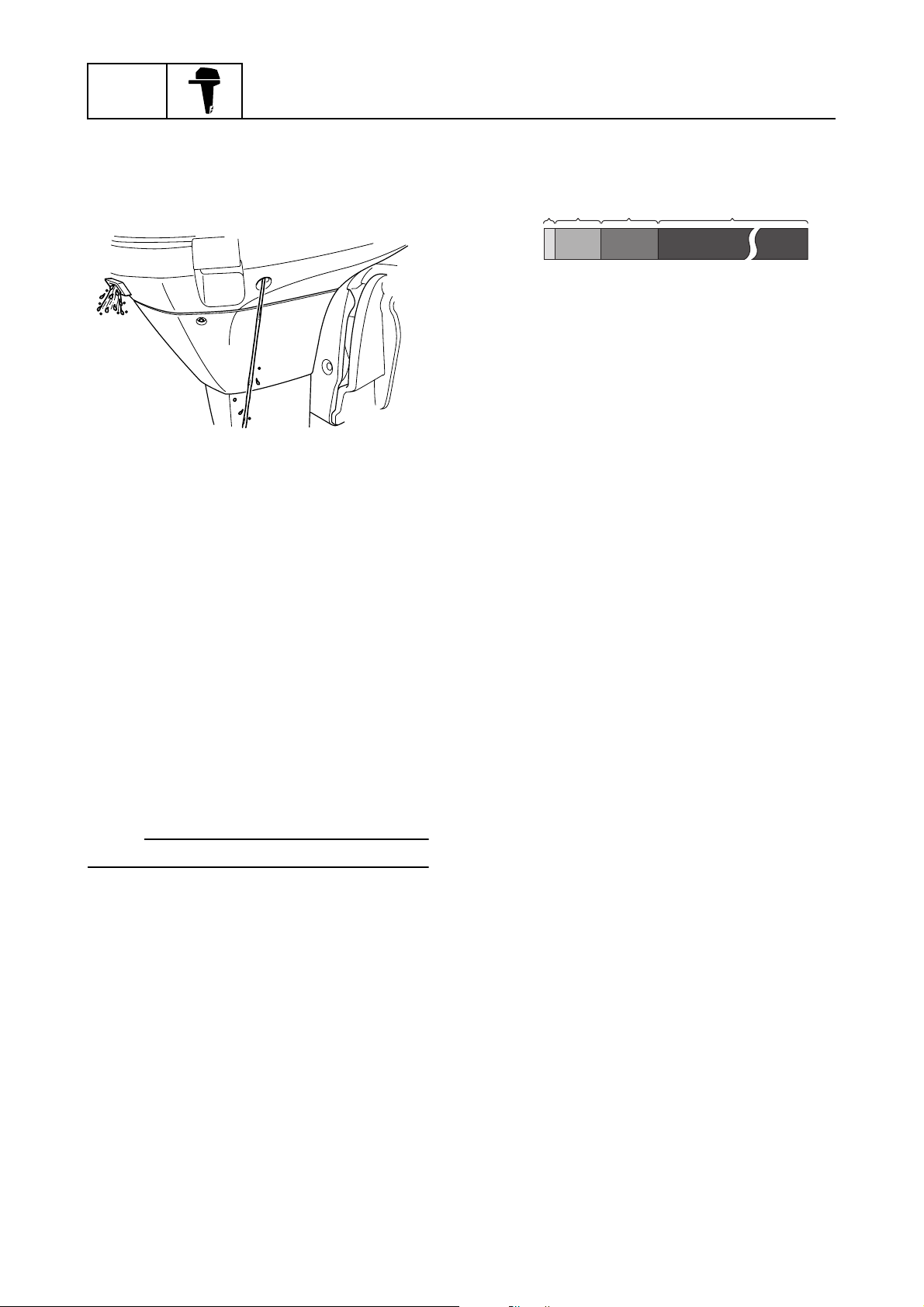
Checking the cooling water pilot
hole
1. Check that cooling water is discharged
from the cooling water pilot hole.
General information
cdaÈb
S60V3140
Test run
1. Start the engine, and then check that the
gear shift operates smoothly.
2. Check the engine idle speed after the
engine has been warmed up.
3. Operate at trolling speed.
4. Run the outboard motor for 1 hour at
3,000 r/min or at half throttle, then for
another hour at 4,000 r/min or at 3/4
throttle.
È
Hour
0
1
210
S60V1120
After test run
1. Check for water in the gear oil.
2. Check for fuel leakage in the cowling.
3. Flush the cooling water passage with
fresh water using the flushing kit and with
the engine running at idle.
5. Check that the outboard motor does not
tilt up when shifting into reverse and that
water does not flow in over the transom.
NOTE:
The test run is part of the break-in operation.
Break-in
During the test run, perform the break-in
operation in the following four stages.
1. First 10 minutes a of operation at idle
2. Fifty minutes b at 3,000 r/min or less
3. One hour c at 4,000 r/min or less
4. Eight hours d at 5,000 r/min or less with
repeated wide-open-throttle operation for
5 minutes or less
1-25
60V3E11
 Loading...