

Yamaha YMU759B Datasheet

YMU759B
MA-2
Mobile Audio 2
Outline
YMU759B is a synthesis LSI for portable telephone that is capable of playing high quality music by utilizing
FM Synthesizer and ADPCM decoder that are included in this device. As a synthesis, YMU759B is equipped
with Yamaha’s original FM synthesizer, with which the device is capable of simultaneously generating up to
16 voices with different tones. Since the device is capable of generating ADPCM data simultaneously
synchronous with the play of the FM synthesizer, various sampled voices can be used as sound effects.
Since the play data of YMU759B are interpreted at anytime through FIFO, the length of the data (playing period)
is not limited, so the device can flexibly support applications such as incoming call melody distribution service.
The hardware sequencer built in this device allows playing of complex music without giving excessive load to
the CPU of the portable telephones. Moreover, the registers of the FM synthesizer can be operated directly for
real time sound generation, allowing, for example, utilization of various sound effects when using the game
software installed in the portable telephone.
YMU759B includes a speaker amplifier with low ripple whose maximum output is 550 mW (SPVDD=3.6V).
The device is also equipped with conventional functions including a vibrator and a circuit for controlling
LEDs synchronous with music.
For the headphone, it is provided with a stereophonic analog output terminal.
For the purpose of enabling YMU759B to demonstrate its full capabilities, Yamaha proposes to use “SMAF:
Synthetic music Mobile Application Format” as a data distribution format that is compatible with multimedia.
Since the SMAF takes a structure that sets importance on the synchronization between sound and images,
various contents can be written into it including incoming call melody with words that can be used for training
karaoke, and commercial channel that combines texts, images and sounds, and others. The hardware sequencer of
YMU759B directly interprets and plays blocks relevant to synthesis (playing music and reproducing ADPCM with
FM synthesizer) that are included in the data distributed in SMAF.
YAMAHA CORPORATION
CATALOG No.:LSI- 4MU759B40
YMU759B CATALOG
2005. 1

YMU759B
Features
FM synthesizer functions
■ Tones
FM synthesizer is capable of creating countless tones theoretically.
When synthesizing tones, it is necessary to designate the number of operators to be used for the synthesis.
Increasing the number of operators allows synthesis of tones that are more intricate and closer to those
generated by natural musical instruments.
YMU759B supports synthesis of tones of two types including 2-operator tones and 4-operator tones.
Because operator's wave shape can be chosen from eight kinds, the quality of sound improves more
remarkably than 2 operator sound of the MA-1 series. (A MA-1 series can choose operator wave shape
fromtwo kinds.)
■ Number of voices simultaneously generated
YMU759B is equipped with 32 operators.
When only 2-operator tones are used: up to 16 voices can be generated simultaneously.
When only 4-operator tones are used: up to 8 voices can be generated simultaneously.
■ Compatible with stereophonic sound generation.
■ Volume control
Channel volume, master volume, expression, and pan pot control in individual channels.
■ Sequencer is built in.
■ Can interpret Mobile Multimedia Format directly.
■ Equipped with four systems of 96 FIFOs for sequence data.
■ Supports direct access that directly controls FM synthesizer.
■ Supports key control with half an octave higher and lower.
ADPCM reproduction function
■ Equipped with ADPCM decoder with 4 bits, 1 channel.
■ Supports two kinds of sampling frequency, 4 kHz and 8 kHz.
■ Sequencer is built in.
■ Equipped with 348 byte FIFO for ADPCM data and 32 byte FIFO for sequence data.
■ Supports direct access that directly controls ADPCM section.
Speaker amplifier and equalizer circuit
■ Output of speaker amplifier: 550 mW when SPVDD=3.6 V, or 400 mW when SPVDD=3.0 V.
■ Balanced input speaker amplifier provides low ripple
■ Built-in equalizer circuit corrects the difference of frequency response among the speakers and forms of bodies.
Interface
■ 4 wire serial interface or 12 wire parallel interface can be selected.
Others
■ PLL is built-in to support master clock input in 2 MHz to 20 MHz range.
■ Provided with a circuit for controlling on/off of LEDs and vibrator. These can be operated synchronous with
the play data.
■ Provided with a stereophonic analog output terminal for headphone.
■ 16 bit stereophonic D/A converter is built in.
■ Supports power down mode. (Typical current: 1 µA or less)
Power supply voltage
■ The power supply includes two power supply sub-systems, analog power supply devoted to speaker amplifier
and power supply for other sections.
■ The power supply for the speaker amplifier (SPVDD) supplies voltages in the range 2.7 V
and other power supplies (VDD) voltages in the range 2.7 V
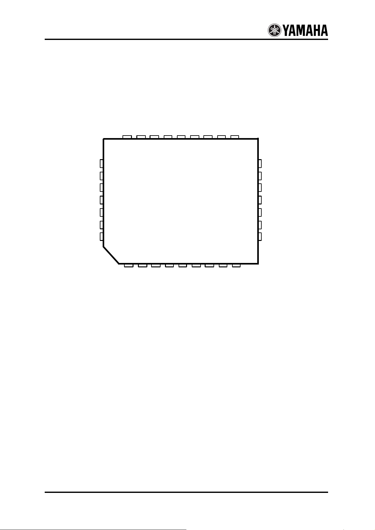
32-pin plastic QFN
■ The plating of pins is lead-free. (YMU759B-QZ)
~ 4.5 V (Typ 3.6 V),
~ 3.3 V (Typ 3.0 V).
-2-
YMU759B
Terminal configuration
SPOUT1
SPOUT2
EXT2
D7
D6
D5
D4
D3
D2
25 24 23 22 21 20 19 18 17
D1
D0
/WR
SDIN (/CS)
SYNC (A0)
SCLK (/RD)
SDOUT
26
27
28
29
30
31
32
123456789
/IRQ
CLKI
EXT1
/RST
PLLC
IFSEL
<32pin QFN Top View>
VDD
VSS
VREF
16
15
14
13
12
11
10
SPVSS
SPVDD
EQ3
EQ2
EQ1
HPOUT-R
HPOUT-L/MONO
-3-
YMU759B
Terminal functions
No. Name I/O Function
1 CLKI Ish
2
EXT1
3 /IRQ O
4 /RST Ish
5 IFSEL I
6 PLLC A
7 VDD -
8 VSS -
9 VREF A
10 HPOUT-L / MONO A
11 HPOUT-R A
12 EQ1 A
13 EQ2 A
14 EQ3 A
15
SPVDD
16 SPVSS -
17 SPOUT1 A
18 SPOUT2 A
19 EXT2 O
20
21
22
D7
D6
D5
I/O
I/O
I/O
23 D4 I/O
24 D3 I/O
25 D2 I/O
26 D1 I/O
27 D0
I/O Parallel I/F data bus 0 (To be open when IFSEL=L)
28 /WR Ish
29 SDIN (/CS) Ish
30 SYNC (A0) Ish
31 SCLK (/RD) Ish
32 SDOUT OD
Comment: Ish= Schmitt input, OD= open drain terminal, A= Analog terminal
(*1) The function changes by setup of the register.
Clock input (2MHz~20MHz)
O
External device control terminal 1 (*1)
Interruption output
Hardware reset input
CPU I/F selection L: Serial I/F, H: Parallel I/F
Connection of capacitor for built in PLL
Connect the 3.3kΩ resistance and the 1000pF capacitor between this terminal
and VSS (*) in series.
(*)Directly connect VSS used here and VSS of 8th pin.
Digital power supply (Typically +3.0V)
Connect 0.1
Ground
Analog reference voltage.
Connect 0.1
Headphone L channel output: can be switched to mono through register setting
Headphone R channel output
Equalizer terminal 1
Equalizer terminal 2
Equalizer terminal 3
Analog power supply (Typically +3.6 V)
-
Connect 0.1
Analog ground for speaker amplifier
Speaker terminal 1
Speaker terminal 2
External device control terminal 2 (*1)
Parallel I/F data bus 7 (*1)
Parallel I/F data bus 6 (*1)
Parallel I/F data bus 5 (*1)
Parallel I/F data bus 4 (To be open when IFSEL=L)
Parallel I/F data bus 3 (To be open when IFSEL=L)
Parallel I/F data bus 2 (To be open when IFSEL=L)
Parallel I/F data bus 1 (To be open when IFSEL=L)
Parallel I/F write pulse (To be open when IFSEL=L)
IFSEL= L Serial I/F data input
IFSEL= H Parallel I/F chip select input
IFSEL= L Serial I/F data decision signal
IFSEL= H Parallel I/F address signal
IFSEL= L Serial I/F bit clock input
IFSEL= H Parallel I/F read pulse
Serial I/F data output (Pull up resistance is necessary for the outside)
µF and 4.7 µF capacitors between this terminal and VSS
µF capacitor between this terminal and VSS
µF and 4.7 µF capacitors between this terminal and SPVSS
-4-
YMU759B
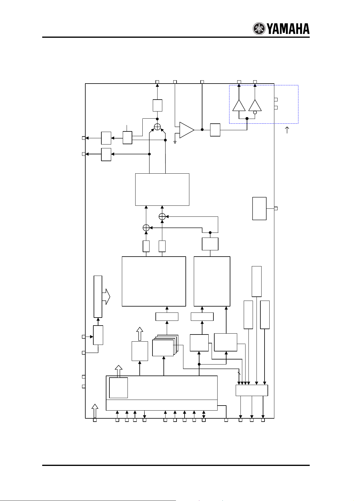
Block diagram
EQ1
EQ
EQ2
Vol
EQ3
SPOUT1
SPOUT2
SPVDD
SPVSS
HPOUT-L /
MONO
HPOUT-R
HP
HP
Mono
Vol L
Vol R
Select
Lch
Rch
16-bit DAC
Lch
Rch
Vol
Vol
VREF
-
+
SP
Vol
Analog power supply
devoted to speaker
am p lifie r
VREF
&
Vol
LPF
VREF
FM
ADPCM
Synthesizer
(Fs= 4 9.7 kHz)
simu ltaneous ly
16 sound generated
Playback
Viblator control
(Fs= 4 or 8kHz)
CLKI
PLLC
VSS
VDD
Timing Generator
PLL
Power
Down
Control
Sequencer
x 4
FM
Register
FIFO
CPU I/F
Sequencer
Seq
ADPCM
FIFO
TIMER
LED control
FIFO
WAVE
ADPCM
4
Mix & Select
SELEC T
A0
/RST
SCLK
SDIN
SYNC
SDOUT
/CS
/RD
/W R
D0 - D7
/IR Q
EXT1
IFS E L
EXT2
-5-
YMU759B
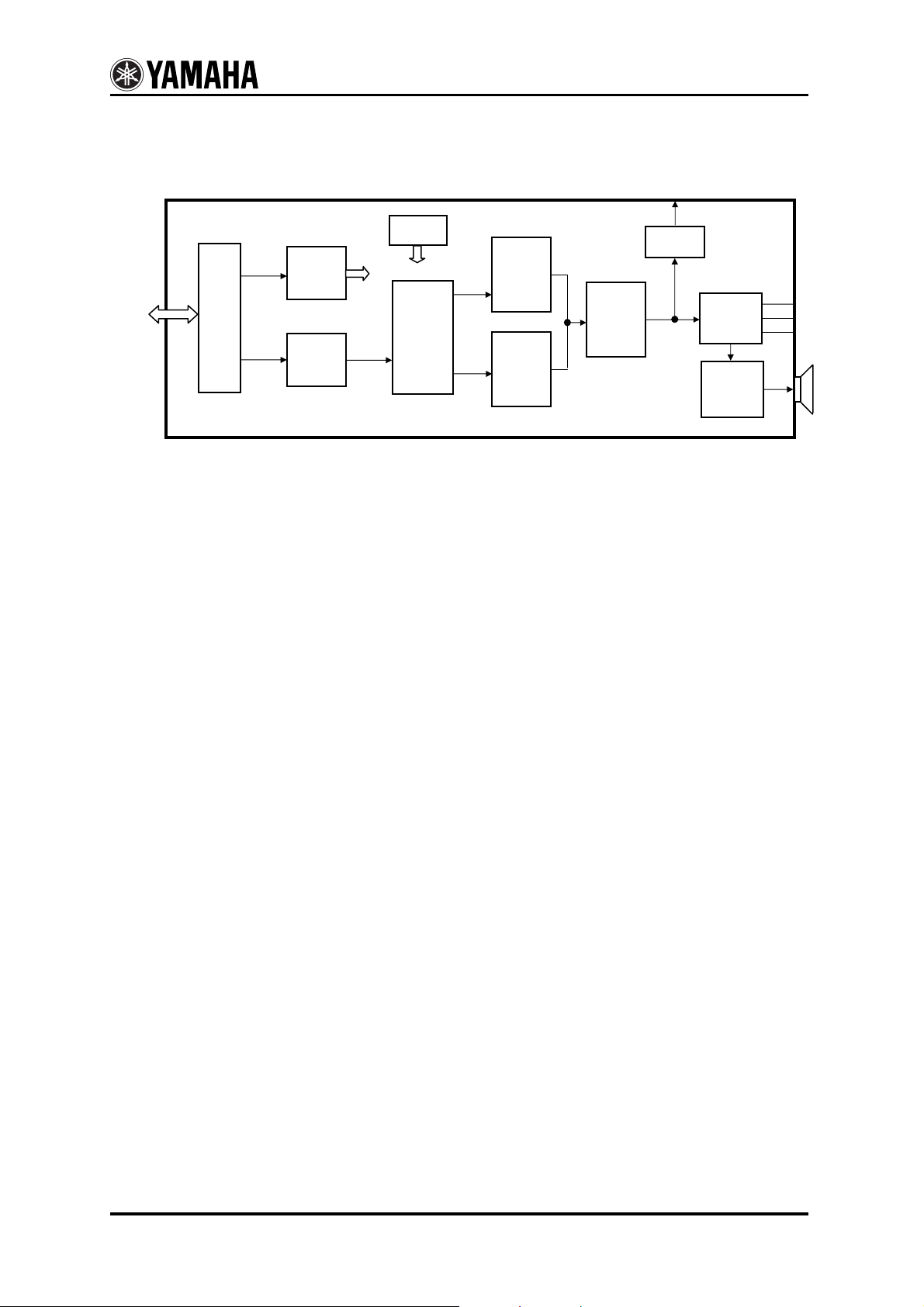
Outline of blocks
Explanation about outline of built-in each blocks and flow of the signal are follows.
CPU interface
Receives commands send from external CPU, interprets the contents, and then writes them into registers by index
address. Controls reading of designated register data.
As interfaces for controlling YMU759B, 4 wire serial and 12 wire parallel interfaces are provided, which can be
selected through IFSEL terminal.
Registers
Register groups that control the LSI except for sequence data.
FM tone register data, various volumes and other control data are store here.
FIFO
Sequence data to move hardware sequencer and ADPCM wave data are stored in FIFO.
This device is equipped with four FIFOs for FM and two FIFOs for ADPCM.
The FIFOs for FM stores sequence data and those for ADPCM stores sequence and waveform data.
The size of FIFOs for FM is 96 bytes, the one for ADPCM data is 384 bytes, and the one for sequence data is 32
bytes.
Hardware sequencer
FIFO is provided as a previous stage of the sequencer which reads sequence data from FIFO to control FM and
ADPCM sections.
The sequence data are compatible with SMAF(Synthetic music Mobile Application Format) proposed by yamaha.
FM synthesis
This is a synthesis that uses Yamaha’s original FM system. It is able to generate up to 16 voices simultaneously.
This section plays in accordance with commands from the sequencer.
It can also play by directly controlling various registers without using the sequencer.
The sampling frequency is 49.7 kHz that complies with stereophonic sound.
ADPCM playback
This section decodes 4 bit ADPCM data to 16 bit data by using the sampling frequency of 4 kHz or 8 kHz.
It can playback one voice. It playback according to command from sequencer.
And it can playback to control various register directly without using sequencer.
CPU Interface
Register
FIFO
Clock
Generate
FM
Sound
Generator
Hardware
Sequencer
ADPCM
Playback
DAC
Headphone
Output
EQ
Amplifier
Speaker
Amplifier
External
Parts
-6-
 Loading...