

YAMAHA YHT-S400 User Manual

Home Theater Package
(Subwoofer Integrated Receiver + Speaker)
YHT-S400
(SR-300 + NS-BR300)
Owner’s Manual
English
IMPORTANT SAFETY INSTRUCTIONS
CAUTION
RISK OF ELECTRIC
SHOCK DO NOT OPEN
CAUTION: TO REDUCE THE RISK OF
ELECTRIC SHOCK, DO NOT REMOVE
COVER (OR BACK). NO USER-
SERVICEABLE PARTS INSIDE. REFER
SERVICING TO QUALIFIED SERVICE
PERSONNEL.
• Explanation of Graphical Symbols
The lightning flash with arrowhead symbol,
within an equilateral triangle, is intended to alert
you to the presence of uninsulated “dangerous
voltage” within the product’s enclosure that may
be of sufficient magnitude to constitute a risk of
electric shock to persons.
The exclamation point within an equilateral
triangle is intended to alert you to the presence of
important operating and maintenance (servicing)
instructions in the literature accompanying the
appliance.
IMPORTANT
Please record the serial number of this unit in the
space below.
MODEL:
Serial No.:
The serial number is located on the rear of the unit.
Retain this Owner’s Manual in a safe place for
future reference.
1 Read these instructions.
2 Keep these instructions.
3 Heed all warnings.
4 Follow all instructions.
5 Do not use this apparatus near water.
6 Clean only with dry cloth.
7 Do not block any ventilation openings. Install in
accordance with the manufacturer’s instructions.
8 Do not install near any heat sources such as radiators,
heat registers, stoves, or other apparatus (including
amplifiers) that produce heat.
9 Do not defeat the safety purpose of the polarized or
grounding-type plug. A polarized plug has two blades
with one wider than the other. A grounding type plug
has two blades and a third grounding prong. The wide
blade or the third prong are provided for your safety. If
the provided plug does not fit into your outlet, consult
an electrician for replacement of the obsolete outlet.
10 Protect the power cord from being walked on or pinched
particularly at plugs, convenience receptacles, and the
point where they exit from the apparatus.
11 Only use attachments/accessories specified by the
manufacturer.
12 Use only with the cart, stand, tripod,
bracket, or table specified by the
manufacturer, or sold with the apparatus.
When a cart is used, use caution when
moving the cart/apparatus combination to
avoid injury from tip-over.
13 Unplug this apparatus during lightning storms or when
unused for long periods of time.
14 Refer all servicing to qualified service personnel.
Servicing is required when the apparatus has been
damaged in any way, such as power-supply cord or plug
is damaged, liquid has been spilled or objects have
fallen into the apparatus, the apparatus has been exposed
to rain or moisture, does not operate normally, or has
been dropped.
2 En
FOR CANADIAN CUSTOMERS
To prevent electric shock, match wide blade of plug
to wide slot and fully insert.
This Class B digital apparatus complies with
Canadian ICES-003.

FCC INFORMATION (for US customers)
1 IMPORTANT NOTICE: DO NOT MODIFY
THIS UNIT!
This product, when installed as indicated in the
instructions contained in this manual, meets FCC
requirements. Modifications not expressly approved
by Yamaha may void your authority, granted by the
FCC, to use the product.
2 IMPORTANT: When connecting this product to
accessories and/or another product use only high
quality shielded cables. Cable/s supplied with this
product MUST be used. Follow all installation
instructions. Failure to follow instructions could void
your FCC authorization to use this product in the
USA.
3 NOTE: This product has been tested and found to
comply with the requirements listed in FCC
Regulations, Part 15 for Class “B” digital devices.
Compliance with these requirements provides a
reasonable level of assurance that your use of this
product in a residential environment will not result in
harmful interference with other electronic devices.
This equipment generates/uses radio frequencies and,
if not installed and used according to the instructions
found in the users manual, may cause interference
harmful to the operation of other electronic devices.
Compliance with FCC regulations does not guarantee
that interference will not occur in all installations. If
this product is found to be the source of interference,
which can be determined by turning the unit “OFF”
and “ON”, please try to eliminate the problem by
using one of the following measures:
Relocate either this product or the device that is being
affected by the interference.
Utilize power outlets that are on different branch
(circuit breaker or fuse) circuits or install AC line
filter/s.
In the case of radio or TV interference, relocate/
reorient the antenna. If the antenna lead-in is 300 ohm
ribbon lead, change the lead-in to coaxial type cable.
If these corrective measures do not produce
satisfactory results, please contact the local retailer
authorized to distribute this type of product. If you can
not locate the appropriate retailer, please contact
Yamaha Electronics Corp., U.S.A. 6660 Orangethorpe
Ave., Buena Park, CA 90620.
The above statements apply ONLY to those products
distributed by Yamaha Corporation of America or its
subsidiaries.
We Want You Listening For A Lifetime
Yamaha and the Electronic Industries Association’s Consumer Electronics Group want you to get the most out
of your equipment by playing it at a safe level. One that lets the sound come through loud and clear without
annoying blaring or distortion – and, most importantly, without affecting your sensitive hearing. Since hearing
damage from loud sounds is often undetectable until it is too late, Yamaha and the Electronic Industries
Association’s Consumer Electronics Group recommend you to avoid prolonged exposure from excessive
volume levels.
3 En

Caution: Read this before operating your unit.
1 To assure the finest performance, please read this
manual carefully. Keep it in a safe place for future
reference.
2 Install this unit in a well ventilated, cool, dry, clean
place - away from direct sunlight, heat sources,
vibration, dust, moisture, and/or cold. For proper
ventilation, allow the following minimum clearances.
Top: 5 cm (2 in)
Rear: 5 cm (2 in)
Sides: 5 cm (2 in)
3 Locate this unit away from other electrical appliances,
motors, or transformers to avoid humming sounds.
4 Do not expose this unit to sudden temperature changes
from cold to hot, and do not locate this unit in an
environment with high humidity (i.e. a room with a
humidifier) to prevent condensation inside this unit,
which may cause an electrical shock, fire, damage to
this unit, and/or personal injury.
5 Avoid installing this unit where foreign objects may fall
onto this unit and/or this unit may be exposed to liquid
dripping or splashing. On the top of this unit, do not
place:
– Other components, as they may cause damage and/or discoloration
on the surface of this unit.
– Burning objects (i.e. candles), as they may cause fire, damage to
this unit, and/or personal injury.
– Containers with liquid in them, as they may fall and liquid may
cause electrical shock to the user and/or damage to this unit.
6 Do not cover this unit with a newspaper, tablecloth,
curtain, etc. in order not to obstruct heat radiation. If the
temperature inside this unit rises, it may cause fire,
damage to this unit, and/or personal injury.
7 Do not plug in this unit to a wall outlet until all
connections are complete.
8 Do not operate this unit upside-down. It may overheat,
possibly causing damage.
9 Do not use force on switches, knobs and/or cords.
10 When disconnecting the power cable from the wall
outlet, grasp the plug; do not pull the cable.
11 Do not clean this unit with chemical solvents; this might
damage the finish. Use a clean, dry cloth.
12 Only voltage specified on this unit must be used. Using
this unit with a higher voltage than specified is
dangerous and may cause fire, damage to this unit, and/
or personal injury. Yamaha will not be held responsible
for any damage resulting from use of this unit with a
voltage other than specified.
13 To prevent damage by lightning, keep the power cable
and outdoor antennas disconnected from a wall outlet or
the unit during a lightning storm.
14 Do not attempt to modify or fix this unit. Contact
qualified Yamaha service personnel when any service is
needed. The cabinet should never be opened for any
reasons.
15 When not planning to use this unit for long periods of
time (i.e. vacation), disconnect the AC power plug from
the wall outlet.
16 Be sure to read the “Troubleshooting” section on
common operating errors before concluding that this
unit is faulty.
17 Before moving this unit, press to set this unit in
standby mode, and disconnect the power supply cable
from the wall outlet.
18 Condensation will form when the surrounding
temperature changes suddenly. Disconnect the power
supply cable from the outlet, then leave the unit alone.
19 Install this unit near the wall outlet and where the AC
power plug can be reached easily.
20 The batteries shall not be exposed to excessive heat such
as sunshine, fire or like.
21 Secure placement or installation is the owner’s
responsibility. Yamaha shall not be liable for any
accident caused by improper placement or installation of
speakers.
WARNING
TO REDUCE THE RISK OF FIRE OR ELECTRIC
SHOCK, DO NOT EXPOSE THIS UNIT TO RAIN
OR MOISTURE.
As long as this unit is connected to the AC wall
outlet, it is not disconnected from the AC power
source even if you turn off this unit by . In this
state, this unit is designed to consume a very small
quantity of power.
■ For U.K. customers
If the socket outlets in the home are not suitable for
the plug supplied with this appliance, it should be cut
off and an appropriate 3 pin plug fitted. For details,
refer to the instructions described below.
Note
The plug severed from the mains lead must be destroyed, as
a plug with bared flexible cord is hazardous if engaged in a
live socket outlet.
■ Special Instructions for U.K. Model
IMPORTANT
THE WIRES IN THE MAINS LEAD ARE
COLOURED IN ACCORDANCE WITH THE
FOLLOWING CODE:
Blue: NEUTRAL
Brown: LIVE
As the colours of the wires in the mains lead of this
apparatus may not correspond with the coloured
markings identifying the terminals in your plug,
proceed as follows:
The wire which is coloured BLUE must be
connected to the terminal which is marked with the
letter N or coloured BLACK. The wire which is
coloured BROWN must be connected to the
terminal which is marked with the letter L or
coloured RED.
Making sure that neither core is connected to the
earth terminal of the three pin plug.
4 En

Contents
INTRODUCTION PREPARATION
INTRODUCTION
Getting started....................................................6
Supplied parts........................................................6
Controls and functions ..........................................7
PREPARATION
Placing ...............................................................10
Placing the speaker .............................................10
Connection ........................................................12
Overview.............................................................12
Connecting a TV................................................. 13
Connecting Blu-ray disc player or
set-top box ....................................................... 13
BASIC OPERATION
Basic playback operation.................................14
Enjoying sound modes .....................................15
Surround mode....................................................15
Stereo mode ........................................................15
UniVolume™......................................................15
Listening to FM broadcasts.............................16
Basic tuning operation ........................................16
Editing the preset FM station..............................16
Using optional equipment................................18
Connecting dock ................................................. 18
Using iPod™.......................................................18
Using Bluetooth™ components..........................19
USEFUL OPERATION
Setup menu ....................................................... 20
Overview .............................................................20
Basic procedure...................................................20
Adjusting the volume balance during
playback...........................................................21
Adjusting high/low frequency sound
(tone control)....................................................21
Adjusting the audio delay....................................21
Setting the audio output ......................................21
Switching on/off the HDMI™ control
function ............................................................21
Changing the brightness of the front panel
display..............................................................22
Changing the setting of the speaker type ............22
Setting the distance between the speakers ..........22
Using the HDMI™ control function ...................23
ADDITIONAL INFORMATION
Additional information.................................... 24
Troubleshooting ..................................................24
Glossary...............................................................27
Specifications ......................................................29
Available signal information...............................30
OPERATION
BASIC
OPERATION
USEFUL
■ About this manual
• In this manual, operations that can be performed using either the front panel buttons or the remote control are
explained using the remote control.
• y indicates a tip for your operation. Notes contain important information about safety and operating
instructions.
• This manual is produced prior to production. Design and specifications are subject to change in part as a result
of improvements, etc. In case of differences between the manual and the product, the product has priority.
INFORMATION
ADDITIONAL
5 En
INTRODUCTION
Getting started
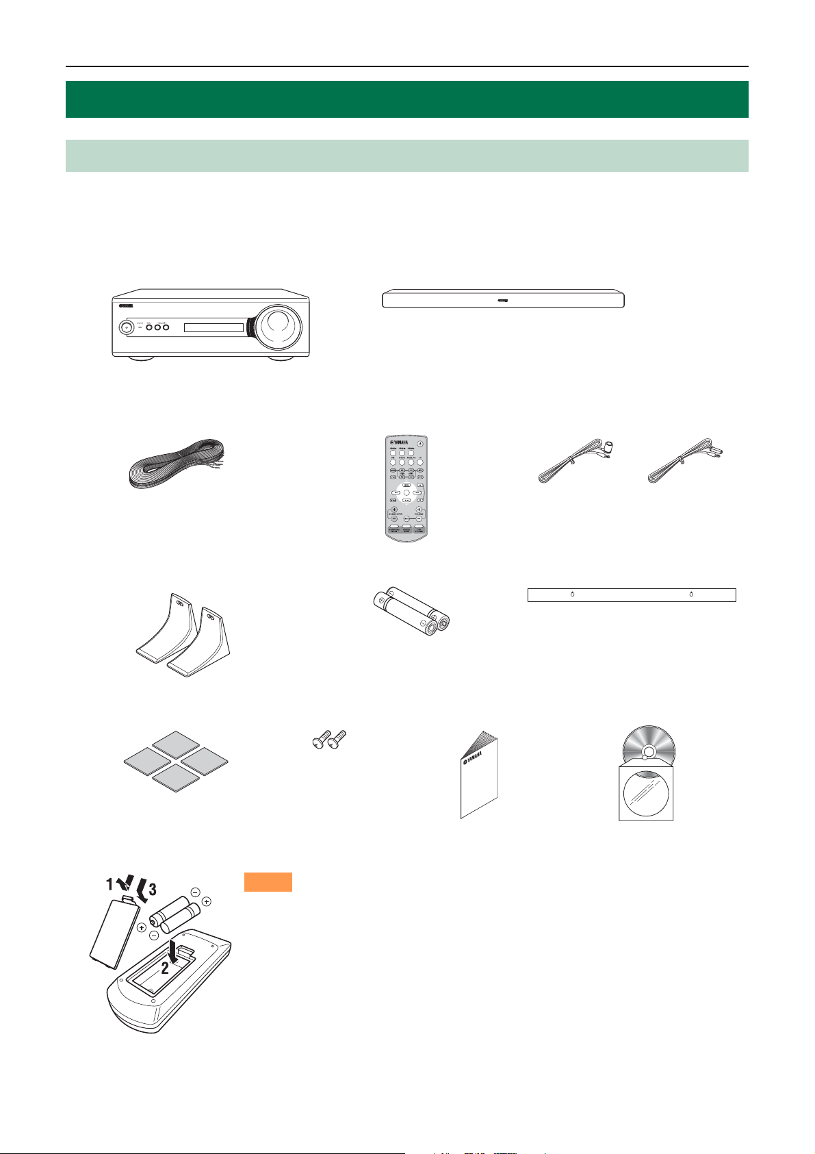
Supplied parts
This product consists of the following items. Before making connections, make sure you have received all of the
following items.
■ Units
Subwoofer Integrated Receiver (SR-300) Speaker (NS-BR300)
■ Accessories
Speaker cable (3 m) Remote control Indoor FM antenna
Stand × 2
(for speaker)
Non-skid pad
(4 pieces)
Screw × 2
(for stand)
■ Installing the batteries
Notes
(U.S.A., Canada and
Asia models)
Battery × 2 (AAA, R03, UM4) Mounting template
Quick Reference
Guide
(Owner’s Manual)
(Europe, Russia and
Australia models)
CD-ROM
6 En
• If the effective operation distance of the remote control decreases considerably, replace
the batteries with two new ones as soon as possible.
• Do not use an old battery together with new one.
• Do not use different types of batteries (for example, alkaline and manganese) together.
Their performance will vary, even if they are similar in shape.
• If the batteries run out, immediately remove them from the remote control to prevent an
explosion or acid leak.
• Dispose of batteries according to regional regulations.
• If a battery starts leaking, dispose of it immediately. Be careful not to let leaking battery
acid come into contact with your skin or clothing. Before inserting new batteries, wipe
the compartment clean.
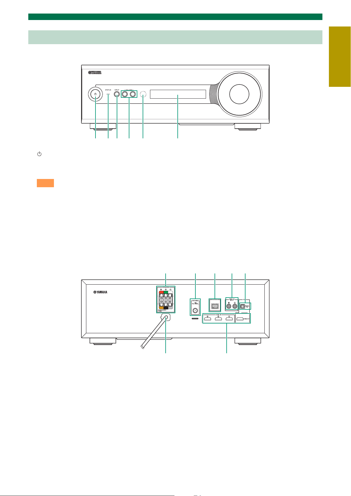
Controls and functions
■ Front panel of the subwoofer integrated receiver
1 2 3 4 5 6
Getting started
INTRODUCTION
1
Turns on the system, or sets it to standby mode.
(☞ P. 14)
Note
A small amount of electricity is consumed to receive
the infrared signal from the remote control even when
the system is in standby mode.
2 STATUS indicator
Lights up to show the system condition. (☞ P. 14)
3 INPUT
Selects an input source you want to listen to.
(☞ P. 14)
4 VOLUME –/+
Controls the volume of the system. (☞ P. 14)
5 Remote control sensor
Receives infrared signals from the remote control.
(☞ P. 9, 12)
6 Front panel display
Shows information about the operational status of
the system. (☞ P. 14)
■ Rear panel of the subwoofer integrated receiver
7 6 5 4 3
1 Power Cable
For connecting an AC wall outlet. (☞ P. 12)
2 HDMI IN 1 - 3/HDMI OUT
• HDMI IN 1 - 3 for connecting HDMI
compatible external components. (☞ P. 13)
• HDMI OUT for connecting an HDMI
compatible TV. (☞ P. 13)
3 DIGITAL IN jack
For connecting optical digital cable to the TV.
(☞ P. 13)
1 2
4 ANALOG INPUT jack
For connecting analog audio cable to external
components. (☞ P. 12)
5 DOCK terminal
For connecting an optional Yamaha iPod universal
dock (such as YDS-11, sold separately) or
Bluetooth wireless audio receiver (such as YBA10, sold separately). (☞ P. 18)
6 ANTENNA terminal
For connecting supplied FM antenna. (☞ P. 12)
7 SPEAKERS terminal
For connecting speakers. (☞ P. 12)
7 En

Getting started
■ Front panel display of the subwoofer integrated receiver
1 2 3 4
8
7
6
1 HDMI indicator
Lights up during normal communication when
HDMI is selected as an input source.
2 Tuner indicators
TUNED indicator
Lights up when the system is receiving a station.
(☞ P. 16)
STEREO indicator
Lights up when the system is receiving a strong
signal from an FM stereo broadcast station in
automatic tuning mode. (☞ P. 16)
AUTO indicator
Flashes when the system is tuning station
automatically. (☞ P. 16)
MEMORY indicator
Flashes when the system is storing a station.
(☞ P. 16, 17)
EMPTY indicator
Lights up when the storing preset number is empty.
(☞ P. 17)
PS/PTY/RT/CT indicator (Europe and
Russia models only)
Lights up according to the available Radio Data
System information. (☞ P. 17)
3 Decoder indicators
The respective indicator lights up when any of the
decoders of the system is activated.
5
4 DOCK indicator
• Lights up when the system is receiving a signal
from an iPod stationed in the Yamaha iPod
universal dock (such as YDS-11, sold
separately) connected to the DOCK terminal of
the subwoofer integrated receiver. (☞ P. 18)
• Lights up while the Yamaha Bluetooth wireless
audio receiver (such as YBA-10, sold
separately) is connected to the Bluetooth
component. (☞ P. 19)
• Flashes while the connected Yamaha Bluetooth
wireless audio receiver (such as YBA-10, sold
separately) and the Bluetooth component are
pairing (☞ P. 19) or while the Yamaha
Bluetooth wireless audio receiver is searching
for the Bluetooth component. (☞ P. 19)
5 VOLUME indicator
• Indicates the current volume level.
• Flashes while the mute function is activated.
(☞ P. 14)
6 Multi information display
Shows the selected input source, current sound
mode and other information.
7 ENHANCER indicator
Lights up when compressed music enhancer
function is activated. (☞ P. 18)
8 UNIVOLUME indicator
Lights up when UniVolume mode is selected.
(☞ P. 15)
8 En
Getting started
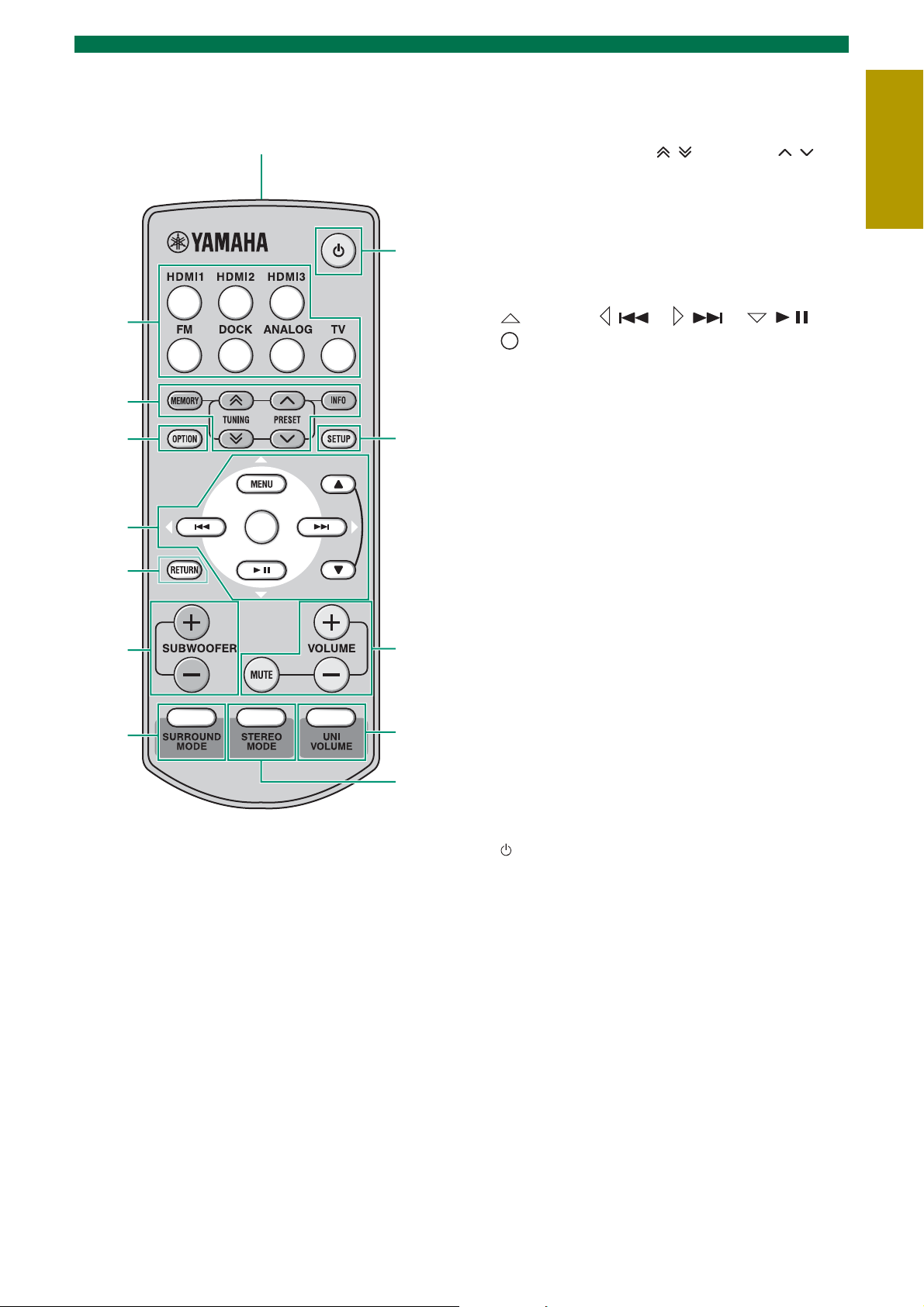
■ Remote control
Infrared signal
transmitter
1
2
3
4
B
A
1 Input buttons
Select an input source you want to listen to.
(☞ P. 14)
2 MEMORY, TUNING / , PRESET / ,
INFO
Control an FM tuner. (☞ P. 16)
3 OPTION
Enters OPTION menu when operating FM
function or using Bluetooth component. (☞ P. 16,
19)
4 (MENU) / ( ) / ( ) / ( ) /
(Center)
• Change the setting.
• Control an iPod. (☞ P. 18)
S / T: Control the wheel of iPod.
5 RETURN
Returns to the previous menu or cancels preset
registration/pairing operation.
6 SUBWOOFER (+/–)
Adjust the volume balance of subwoofer.
(☞ P. 21)
INTRODUCTION
5
6
7
@
9
8
7 SURROUND MODE
Selects the surround mode. (☞ P. 15)
8 STEREO MODE
Turns extended stereo mode on and off alternately.
(☞ P. 15)
9 UNIVOLUME
Turns UniVolume mode on and off. (☞ P. 15)
0 VOLUME (+/–)/MUTE
Control the volume of the system. (☞ P. 14)
A SETUP
Enters the setup menu. (☞ P. 20)
B
Turns on the system, or sets it to standby mode.
(☞ P. 14)
9 En
PREPARATION
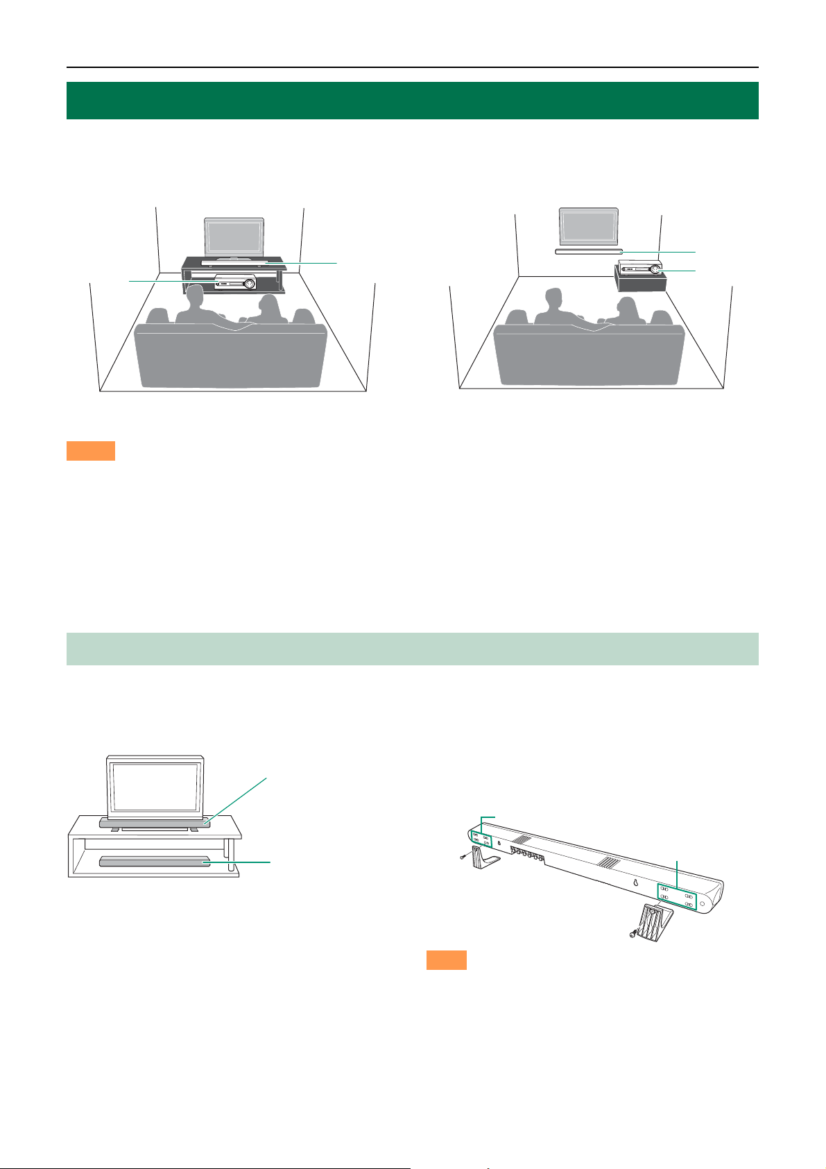
Placing
To enjoy quality sound thoroughly, place this system in the appropriate positions, and install the components
properly. The following illustrations are the setting images of this system.
Example 1: Placing the speaker beneath your TV
2
1
1 Subwoofer integrated receiver (SR-300) 2 Speaker (NS-BR300)
Notes
• Do not place this system on/under any other components such as Blu-ray disc player in a pile. The vibration of this system
may cause system failure, etc. in other components.
• Keep enough ventilation space on the front, rear, and bottom side (that attached legs) of this system. Do not place this
system on a thick carpet etc.
• If the picture on your CRT TV screen becomes blurred or distorted, we recommend moving the system away from your TV.
• Low frequency sound produced by the subwoofer integrated receiver may be heard differently depending on the listening
position and subwoofer location. To enjoy desired sounds, try changing the location of the subwoofer integrated receiver.
• Depending on your installation environment, connections to external components can be done before installing this system.
We recommend that you temporarily place and arrange all components in order to decide which procedure is best done first.
Example 2: Mounting the speaker on the wall
2
1
Placing the speaker
You can place the speaker on a rack or attach it to a wall. Select an installation method that suits your environment.
■ Placing the speaker beneath/under a TV
Put the speaker on the stands and secure
Example 1:
With attaching TV
stand
Example 2:
Without attaching
TV stand
y
• If there is any obstacle (TV stand, etc.) under the speaker,
use the supplied stands as shown in Example 1.
• If you are not using the supplied stands as shown in
Example 2, attach the supplied non-skid pads to the
bottom of the speaker.
them with the supplied screws as shown
in the illustration below.
Screw holes
Screw holes
Note
You can adjust the height and width at which to attach
the stands to the speaker horizontally by selecting
screw holes in the back of the speaker.
The above illustration shows attaching the stands
using the lower and inner screw holes.
10 En
 Loading...